JP4773586B2 - Suspension tool for rechargeable electric tools - Google Patents
Suspension tool for rechargeable electric tools Download PDFInfo
- Publication number
- JP4773586B2 JP4773586B2 JP2011072829A JP2011072829A JP4773586B2 JP 4773586 B2 JP4773586 B2 JP 4773586B2 JP 2011072829 A JP2011072829 A JP 2011072829A JP 2011072829 A JP2011072829 A JP 2011072829A JP 4773586 B2 JP4773586 B2 JP 4773586B2
- Authority
- JP
- Japan
- Prior art keywords
- tool
- housing
- base end
- locking portion
- hanging tool
- Prior art date
- Legal status (The legal status is an assumption and is not a legal conclusion. Google has not performed a legal analysis and makes no representation as to the accuracy of the status listed.)
- Active
Links
Images


Landscapes
- Portable Power Tools In General (AREA)
Description
本発明は、インパクトドライバ等の充電式電動工具を携帯するために用いられる充電式電動工具用の吊り下げ具に関する。 The present invention relates to a hanging tool for a rechargeable power tool used to carry a rechargeable power tool such as an impact driver.
充電式電動工具には、作業者が腰のベルト等に掛止させて吊り下げ携帯することができるように、吊り下げ具が設けられる場合がある。例えば特許文献1には、電動工具の本体へその側面に沿って着脱可能に装着され、本体の後方へ係止部分を突出させた係止具(吊り下げ具)が、特許文献2には、端部に設けた突起を工具本体の穴に挿入して回転可能とした吊り具(吊り下げ具)が夫々記載されている。 The rechargeable electric tool may be provided with a hanging tool so that an operator can hang it around a waist belt or the like and carry it. For example, Patent Literature 1 discloses a locking tool (hanging tool) that is detachably attached to the main body of an electric tool along the side surface thereof, and has a locking portion protruding rearward of the main body. A hanging tool (hanging tool) that can be rotated by inserting a protrusion provided at an end portion into a hole of a tool body is described.
充電式電動工具は、本体から下方に伸びたハンドルの下端に質量の大きいバッテリーが装着される。従って、特許文献1のように本体の後方に吊り下げ具が設けられると、ベルト等に掛止させた際に電動工具が前後に揺れやすく、携帯時の安定性が悪い。特許文献2のようにハンドルの下端に設ければ、前後の揺れは抑えられるが、吊り下げ具の回転構造によって電動工具が左右に揺れる場合があり、結局安定性を損なうことになる。また、吊り下げ具がハンドルの後面側に設けられるため、本体の先端側(ビット側)が側方へ飛び出す格好となり、作業の邪魔になってしまう。
The rechargeable electric tool has a battery with a large mass attached to the lower end of a handle that extends downward from the main body. Therefore, when a hanging tool is provided on the rear side of the main body as in Patent Document 1, the power tool is likely to swing back and forth when hooked on a belt or the like, and the stability when carried is poor. If it is provided at the lower end of the handle as in
そこで、本発明は、充電式電動工具を腰のベルト等に収まりよく携帯でき、携帯時の安定性も高くなる充電式電動工具用の吊り下げ具を提供することを目的としたものである。 SUMMARY OF THE INVENTION Accordingly, an object of the present invention is to provide a hanging tool for a rechargeable electric tool that can be carried in a waist belt or the like and can be carried well, and has high stability when carried.
上記目的を達成するために、請求項1に記載の発明は、ハウジングの下端にバッテリーが装着される充電式電動工具を携帯するためにハウジングに装着される吊り下げ具であって、ハウジングの下端際の側面にネジ止め可能な基端部と、その基端部から突出する係止部とを備え、基端部に、側面への装着面から突出し、側面に形成された凹部に挿入可能な回り止め部を、軸体によって当該軸体を中心に回転可能に設けると共に、軸体を中心とする円周上に、ネジ止め用の複数の取付孔を形成して、回り止め部を凹部に挿入した状態で取付孔から基端部を側面にネジ止めすることで、係止部をハウジングから後方へ突出させた状態でハウジングに装着可能とすると共に、取付孔の選択により、係止部の突出角度が異なる複数の姿勢で装着可能としたことを特徴とするものである。 In order to achieve the above object, a first aspect of the present invention is a hanging tool attached to a housing for carrying a rechargeable electric tool in which a battery is attached to the lower end of the housing, the lower end of the housing A base end portion that can be screwed to the side surface and a locking portion that protrudes from the base end portion, protrudes from the mounting surface to the side surface, and can be inserted into a recess formed on the side surface The anti-rotation part is provided by a shaft body so as to be rotatable around the shaft body, and a plurality of mounting holes for screwing are formed on the circumference centering on the shaft body so that the anti-rotation part is formed into a recess. By screwing the base end to the side surface from the mounting hole in the inserted state, the locking portion can be mounted on the housing in a state of protruding rearward from the housing, and by selecting the mounting hole, Can be installed in multiple postures with different protrusion angles It is characterized in that the.
請求項1に記載の発明によれば、係止部を後ろ向きに突出させて装着できるので、充電式電動工具を腰のベルト等に収まりよく携帯でき、携帯時の安定性も高くなる。
また、回り止め部と凹部との採用により、吊り下げ具をハウジングへ簡単且つ確実に装着でき、携帯時の安定性がより高くなる。
さらに、ハウジングの左右に凹部があれば両側面の何れにも装着できるので、取扱いがし易い方を選択して充電式電動工具を携帯でき、より使い勝手が向上する。
そして、吊り下げ具を複数の姿勢で装着可能としたことで、係止部の突出角度の選択が可能となり、使い勝手の一層の向上が図られる。
According to the first aspect of the present invention, since the engaging portion can be protruded backward and attached, the rechargeable electric tool can be easily carried in a waist belt or the like, and the stability when carried can be improved.
In addition, the adoption of the rotation preventing portion and the recessed portion makes it possible to easily and reliably attach the hanging tool to the housing, and the stability at the time of carrying becomes higher.
Furthermore, if there are recesses on the left and right sides of the housing, it can be mounted on either side, so the rechargeable electric tool can be carried by selecting the one that is easy to handle and the usability is further improved.
Since the hanging tool can be mounted in a plurality of postures, the protrusion angle of the locking portion can be selected, and the usability can be further improved.
以下、本発明の実施の形態を図面に基づいて説明する。
図1は、充電式電動工具の一例であるインパクトドライバの斜視図で、まずインパクトドライバ1は、モータ及び回転打撃機構を内設した本体2の下方に、ハウジングであるハンドル3を延設し、そのハンドル3の下端にバッテリーであるバッテリーパック4を装着した構成となっている。ハンドル3とバッテリーパック4との装着は、ハンドル3の下端で拡開状に形成された装着部5の左右に、一対のガイドレール6,6を形成し、そのガイドレール6,6間に、バッテリーパック4の上面に設けた図示しない一対のスライドレールを前方からスライドさせる構造で、このスライドにより、スライドレールがガイドレール6,6に保持されると共に、装着部5とバッテリーパック4の上面とに設けた端子同士が電気的接続される。7は、バッテリーパック4の装着位置で装着部5の前端に係止するロックボタンである。
Hereinafter, embodiments of the present invention will be described with reference to the drawings.
FIG. 1 is a perspective view of an impact driver which is an example of a rechargeable electric tool. First, the impact driver 1 extends a
また、ハンドル3の下端際となる左右のガイドレール6,6の外面には、吊り下げ具20の取付部8が夫々設けられている。この取付部8は、ネジ孔9と、そのネジ孔9の上方前寄りで前後方向に形成された凹部としてのスリット10とからなり、左右のガイドレール6,6間で対称となる位置で夫々形成されている。
In addition, on the outer surfaces of the left and
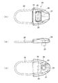
一方、吊り下げ具20は、図2,3に示すように、板状の基端部21と、その基端部21に連結された係止部22とからなる。基端部21における幅方向の中心には、先端を直交状に突出させたL字状の回り止め片23(回り止め部)が、リベット24によって回転可能に設けられている。また、回り止め片23の係止部22側には、回り止め片23をスリット10に差し込んだ状態でネジ孔9へのネジ11のねじ込みを可能とする一対の取付孔25,25が、リベット24の軸心を通る基端部21の中心線を挟んだ対称位置に形成されている。26は、基端部21の表側及び周囲を覆う樹脂製のカバーで、表側には、取付孔25,25を露出させる窓27が形成されている。
さらに、係止部22は、U字状の金属棒で、両端を基端部21に連結することで、基端部21からループ状に突出している。
On the other hand, as shown in FIGS. 2 and 3, the
Furthermore, the latching | locking
以上の如く構成されたインパクトドライバ1及び吊り下げ具20においては、左右何れかの取付部8において、係止部22を後ろ向きにした吊り下げ具20の回り止め片23をスリット10に挿入し、上下何れかの取付孔25を選択してネジ11を貫通させ、ネジ孔9にねじ込むと、図5に示すように、吊り下げ具20は、係止部22を装着部5及びバッテリーパック4から後方へ突出させた状態でインパクトドライバ1に装着される。よって、インパクトドライバ1を携帯する場合は、インパクトドライバ1を逆さまにして、図6に示すように、吊り下げ具20の係止部22を作業者の腰に装着したカラビナ12等に係止させれば、インパクトドライバ1を吊り下げ携帯することができる。なお、左右逆に携帯したい場合は、吊り下げ具20を反対側の取付部8に取り付ければよい。回り止め片23は回転可能であるため、左右逆にしても支障なくスリット10への挿入は可能である。
In the impact driver 1 and the
このように、上記形態のインパクトドライバ1及び吊り下げ具20によれば、下端にバッテリーパック4が装着されるハンドル3の下端際の側面に、端部に係止部22を備えた吊り下げ具20を、係止部22を後方へ突出させた状態で装着したことで、腰のベルト等に収まりよく携帯でき、携帯時の安定性も高くなる。
特にここでは、吊り下げ具20の基端部21をハンドル3の側面にネジ止めする一方、そのネジ止め位置と異なる位置で基端部21に突設した回り止め片23を、ハンドル3の側面に形成されたスリット10に挿入させて吊り下げ具20の装着を行うことで、吊り下げ具20がハンドル3へ簡単且つ確実に装着され、携帯時の安定性がより高くなる。
As described above, according to the impact driver 1 and the hanging
In particular, here, the
さらに、吊り下げ具20をネジ止めするネジ孔9とスリット10とをハンドル3の左右の両側面に夫々対称に形成して、吊り下げ具20を両側面の何れにも装着可能としたことで、取扱いがし易い方を選択してインパクトドライバ1を携帯でき、より使い勝手が向上する。
そして、吊り下げ具20を係止部22の突出角度が異なる複数の姿勢で装着可能としたことで、係止部22の突出角度の選択が可能となり、使い勝手の一層の向上が図られる。
Furthermore, the
And since the hanging
なお、吊り下げ具において、例えば取付孔の数を増やして係止部の突出角度の調整をより細かく行えるようにしてもよい。この場合、夫々独立した取付孔を並設してもよいが、隣接する取付孔同士が端部間で繋がる連続状に形成することもできる。また、取付孔の増加による構造に限らず、回り止め片やスリットの数を増やすことでも同様に吊り下げ具を複数の姿勢で装着可能となる。
さらに、吊り下げ具の装着形態は、回り止め部をピン形状に、凹部をそれに合わせた丸形状に夫々形成したり、回り止め部を基端部と別体とせずに基端部に直接突設してハウジングの凹部に嵌合させたり等の設計変更が考えられる。
In the hanging tool, for example, the number of mounting holes may be increased so that the protrusion angle of the locking portion can be adjusted more finely. In this case, independent mounting holes may be provided in parallel, but they can also be formed in a continuous shape in which adjacent mounting holes are connected between the end portions. Moreover, not only the structure by the increase in an attachment hole but it can mount | wear with a hanging tool with a several attitude | position similarly by increasing the number of rotation prevention pieces and slits.
In addition, the hanging device can be mounted in the form of a pin that has a rotation-preventing portion and a round shape that has a concave portion that matches it, or it can project directly to the base end without being separated from the base end. It is possible to change the design such as installing and fitting in the recess of the housing.
一方、係止部も、上記形態ではループ状としてカラビナに係止させているが、これと逆に、係止部をカラビナにして腰のベルト等に設けたリングに係止させたり、係止部をフック状にしたりしても差し支えない。
その他、充電式電動工具の形態も、バッテリーパックの装着がスライド式でなく、ハンドルの下方からバッテリーパックの上部を差し込む構造であっても、本発明は採用可能である。勿論充電式電動工具としてはインパクトドライバに限らず、インパクトレンチや電動ドライバ等の他のタイプであっても吊り下げ具による吊り下げ携帯は可能である。
On the other hand, the locking portion is also locked to the carabiner as a loop shape in the above form, but conversely, the locking portion is locked to a ring provided on the waist belt or the like with the locking portion as a carabiner. It does not matter if the part is hooked.
In addition, the present invention can also be applied to a rechargeable electric tool having a structure in which the battery pack is not slid and the upper part of the battery pack is inserted from below the handle. Of course, the rechargeable electric tool is not limited to the impact driver, and other types such as an impact wrench and an electric driver can be suspended and carried by a hanging tool.
1・・インパクトドライバ、2・・本体、3・・ハンドル、4・・バッテリーパック、5・・装着部、8・・取付部、9・・ネジ孔、10・・スリット、11・・ネジ、12・・カラビナ、20・・吊り下げ具、21・・基端部、22・・係止部、23・・回り止め片、25・・取付孔、26・・カバー。
1..Impact
Claims (1)
前記ハウジングの下端際の側面にネジ止め可能な基端部と、その基端部から突出する係止部とを備え、
前記基端部に、前記側面への装着面から突出し、前記側面に形成された凹部に挿入可能な回り止め部を、軸体によって当該軸体を中心に回転可能に設けると共に、前記軸体を中心とする円周上に、ネジ止め用の複数の取付孔を形成して、
前記回り止め部を前記凹部に挿入した状態で前記取付孔から前記基端部を前記側面にネジ止めすることで、前記係止部を前記ハウジングから後方へ突出させた状態で前記ハウジングに装着可能とすると共に、前記取付孔の選択により、前記係止部の突出角度が異なる複数の姿勢で装着可能としたことを特徴とする充電式電動工具用の吊り下げ具。 A hanging tool attached to the housing for carrying a rechargeable electric tool with a battery attached to the lower end of the housing,
A base end portion that can be screwed to a side surface near the lower end of the housing, and a locking portion protruding from the base end portion,
The base end portion is provided with a rotation preventing portion that protrudes from the mounting surface on the side surface and can be inserted into a recess formed on the side surface, and is rotatable about the shaft body by the shaft body. A plurality of mounting holes for screwing are formed on the center circumference,
With the locking portion inserted into the recess, the base end can be screwed to the side surface from the mounting hole, so that the locking portion can be mounted on the housing in a state of protruding rearward from the housing. A hanging tool for a rechargeable electric tool characterized in that it can be mounted in a plurality of postures with different projection angles of the locking portion by selecting the mounting hole.
Priority Applications (1)
| Application Number | Priority Date | Filing Date | Title |
|---|---|---|---|
| JP2011072829A JP4773586B2 (en) | 2011-03-29 | 2011-03-29 | Suspension tool for rechargeable electric tools |
Applications Claiming Priority (1)
| Application Number | Priority Date | Filing Date | Title |
|---|---|---|---|
| JP2011072829A JP4773586B2 (en) | 2011-03-29 | 2011-03-29 | Suspension tool for rechargeable electric tools |
Related Parent Applications (1)
| Application Number | Title | Priority Date | Filing Date |
|---|---|---|---|
| JP2008207278A Division JP5352153B2 (en) | 2008-08-11 | 2008-08-11 | Rechargeable power tool |
Publications (2)
| Publication Number | Publication Date |
|---|---|
| JP2011131377A JP2011131377A (en) | 2011-07-07 |
| JP4773586B2 true JP4773586B2 (en) | 2011-09-14 |
Family
ID=44344652
Family Applications (1)
| Application Number | Title | Priority Date | Filing Date |
|---|---|---|---|
| JP2011072829A Active JP4773586B2 (en) | 2011-03-29 | 2011-03-29 | Suspension tool for rechargeable electric tools |
Country Status (1)
| Country | Link |
|---|---|
| JP (1) | JP4773586B2 (en) |
Families Citing this family (2)
| Publication number | Priority date | Publication date | Assignee | Title |
|---|---|---|---|---|
| WO2013014914A2 (en) | 2011-07-24 | 2013-01-31 | Makita Corporation | Adapter for power tools, power tool system and method of operating the same |
| USD718594S1 (en) * | 2012-03-02 | 2014-12-02 | Power Box Ag | Tool bit driver |
Family Cites Families (7)
| Publication number | Priority date | Publication date | Assignee | Title |
|---|---|---|---|---|
| JP3853551B2 (en) * | 1999-12-06 | 2006-12-06 | 株式会社マキタ | Nailing machine |
| DE60134437D1 (en) * | 2000-08-11 | 2008-07-24 | Milwaukee Electric Tool Corp | hand milling machine |
| JP3553585B2 (en) * | 2001-03-02 | 2004-08-11 | 日立工機株式会社 | Electric tool |
| US20060104735A1 (en) * | 2002-03-15 | 2006-05-18 | Zeiler Jeffrey M | Tool and accessory connecting system |
| JP2004174646A (en) * | 2002-11-26 | 2004-06-24 | Matsushita Electric Works Ltd | Portable power tool |
| US20060022002A1 (en) * | 2004-08-02 | 2006-02-02 | Joel Marks | Accessory bit carrier |
| US7318487B2 (en) * | 2005-11-07 | 2008-01-15 | Besco Pneumatic Corp. | Pneumatic tool with an adjustable clip |
-
2011
- 2011-03-29 JP JP2011072829A patent/JP4773586B2/en active Active
Also Published As
| Publication number | Publication date |
|---|---|
| JP2011131377A (en) | 2011-07-07 |
Similar Documents
| Publication | Publication Date | Title |
|---|---|---|
| JP5352153B2 (en) | Rechargeable power tool | |
| JP5379625B2 (en) | Electric tool | |
| EP2332697B1 (en) | Hook for electric power tools and electric power tool equipped with the hook | |
| JP5655057B2 (en) | Impact tool and socket for impact tool | |
| JP5416649B2 (en) | Electric tool and suspension tool for electric tool | |
| JP2017159419A (en) | Tip tool holder and electric tool | |
| JP6792954B2 (en) | Rotating tool | |
| WO2014017113A1 (en) | Hook mounting structure for electric tool | |
| JP4773586B2 (en) | Suspension tool for rechargeable electric tools | |
| JP6979339B2 (en) | Battery device | |
| TWI742069B (en) | electrical tools | |
| JP5360345B2 (en) | Power tools | |
| JP3858153B2 (en) | Portable power tools | |
| JP7338841B2 (en) | tool holder | |
| JP4383750B2 (en) | Hook mounting structure for rechargeable power tools | |
| JP2006272486A (en) | Power tool | |
| JP2013144348A (en) | Fall-off preventive structure of socket in power tool | |
| JP3152079U (en) | Tool bag fitting | |
| JP2016101621A (en) | Power tool | |
| JP7272698B2 (en) | tool holder | |
| JP3208444U (en) | Tool holder | |
| JP7143761B2 (en) | Hooks for equipment and equipment | |
| JP6778289B2 (en) | Rotating tool | |
| JP2001191269A (en) | Mounting structure of hook on power tool | |
| JP2009196009A (en) | Power tool |
Legal Events
| Date | Code | Title | Description |
|---|---|---|---|
| A621 | Written request for application examination |
Free format text: JAPANESE INTERMEDIATE CODE: A621 Effective date: 20110330 |
|
| A871 | Explanation of circumstances concerning accelerated examination |
Free format text: JAPANESE INTERMEDIATE CODE: A871 Effective date: 20110411 |
|
| TRDD | Decision of grant or rejection written | ||
| A975 | Report on accelerated examination |
Free format text: JAPANESE INTERMEDIATE CODE: A971005 Effective date: 20110513 |
|
| A01 | Written decision to grant a patent or to grant a registration (utility model) |
Free format text: JAPANESE INTERMEDIATE CODE: A01 Effective date: 20110524 |
|
| A61 | First payment of annual fees (during grant procedure) |
Free format text: JAPANESE INTERMEDIATE CODE: A61 Effective date: 20110623 |
|
| FPAY | Renewal fee payment (event date is renewal date of database) |
Free format text: PAYMENT UNTIL: 20140701 Year of fee payment: 3 |
|
| R150 | Certificate of patent or registration of utility model |
Ref document number: 4773586 Country of ref document: JP Free format text: JAPANESE INTERMEDIATE CODE: R150 Free format text: JAPANESE INTERMEDIATE CODE: R150 |
|
| FPAY | Renewal fee payment (event date is renewal date of database) |
Free format text: PAYMENT UNTIL: 20140701 Year of fee payment: 3 |
|
| R250 | Receipt of annual fees |
Free format text: JAPANESE INTERMEDIATE CODE: R250 |
|
| R250 | Receipt of annual fees |
Free format text: JAPANESE INTERMEDIATE CODE: R250 |
|
| R250 | Receipt of annual fees |
Free format text: JAPANESE INTERMEDIATE CODE: R250 |
|
| R250 | Receipt of annual fees |
Free format text: JAPANESE INTERMEDIATE CODE: R250 |
|
| R250 | Receipt of annual fees |
Free format text: JAPANESE INTERMEDIATE CODE: R250 |
|
| R250 | Receipt of annual fees |
Free format text: JAPANESE INTERMEDIATE CODE: R250 |
|
| R250 | Receipt of annual fees |
Free format text: JAPANESE INTERMEDIATE CODE: R250 |
|
| R250 | Receipt of annual fees |
Free format text: JAPANESE INTERMEDIATE CODE: R250 |
|
| R250 | Receipt of annual fees |
Free format text: JAPANESE INTERMEDIATE CODE: R250 |
|
| R250 | Receipt of annual fees |
Free format text: JAPANESE INTERMEDIATE CODE: R250 |