JP4767488B2 - Magnetic levitation pump - Google Patents
Magnetic levitation pump Download PDFInfo
- Publication number
- JP4767488B2 JP4767488B2 JP2003363607A JP2003363607A JP4767488B2 JP 4767488 B2 JP4767488 B2 JP 4767488B2 JP 2003363607 A JP2003363607 A JP 2003363607A JP 2003363607 A JP2003363607 A JP 2003363607A JP 4767488 B2 JP4767488 B2 JP 4767488B2
- Authority
- JP
- Japan
- Prior art keywords
- impeller
- casing
- pump
- ferromagnetic body
- magnetic
- Prior art date
- Legal status (The legal status is an assumption and is not a legal conclusion. Google has not performed a legal analysis and makes no representation as to the accuracy of the status listed.)
- Expired - Fee Related
Links
Images


Classifications
-
- F—MECHANICAL ENGINEERING; LIGHTING; HEATING; WEAPONS; BLASTING
- F04—POSITIVE - DISPLACEMENT MACHINES FOR LIQUIDS; PUMPS FOR LIQUIDS OR ELASTIC FLUIDS
- F04D—NON-POSITIVE-DISPLACEMENT PUMPS
- F04D29/00—Details, component parts, or accessories
- F04D29/04—Shafts or bearings, or assemblies thereof
- F04D29/046—Bearings
- F04D29/048—Bearings magnetic; electromagnetic
-
- A—HUMAN NECESSITIES
- A61—MEDICAL OR VETERINARY SCIENCE; HYGIENE
- A61M—DEVICES FOR INTRODUCING MEDIA INTO, OR ONTO, THE BODY; DEVICES FOR TRANSDUCING BODY MEDIA OR FOR TAKING MEDIA FROM THE BODY; DEVICES FOR PRODUCING OR ENDING SLEEP OR STUPOR
- A61M60/00—Blood pumps; Devices for mechanical circulatory actuation; Balloon pumps for circulatory assistance
- A61M60/10—Location thereof with respect to the patient's body
- A61M60/122—Implantable pumps or pumping devices, i.e. the blood being pumped inside the patient's body
- A61M60/165—Implantable pumps or pumping devices, i.e. the blood being pumped inside the patient's body implantable in, on, or around the heart
- A61M60/178—Implantable pumps or pumping devices, i.e. the blood being pumped inside the patient's body implantable in, on, or around the heart drawing blood from a ventricle and returning the blood to the arterial system via a cannula external to the ventricle, e.g. left or right ventricular assist devices
-
- A—HUMAN NECESSITIES
- A61—MEDICAL OR VETERINARY SCIENCE; HYGIENE
- A61M—DEVICES FOR INTRODUCING MEDIA INTO, OR ONTO, THE BODY; DEVICES FOR TRANSDUCING BODY MEDIA OR FOR TAKING MEDIA FROM THE BODY; DEVICES FOR PRODUCING OR ENDING SLEEP OR STUPOR
- A61M60/00—Blood pumps; Devices for mechanical circulatory actuation; Balloon pumps for circulatory assistance
- A61M60/20—Type thereof
- A61M60/205—Non-positive displacement blood pumps
- A61M60/216—Non-positive displacement blood pumps including a rotating member acting on the blood, e.g. impeller
-
- A—HUMAN NECESSITIES
- A61—MEDICAL OR VETERINARY SCIENCE; HYGIENE
- A61M—DEVICES FOR INTRODUCING MEDIA INTO, OR ONTO, THE BODY; DEVICES FOR TRANSDUCING BODY MEDIA OR FOR TAKING MEDIA FROM THE BODY; DEVICES FOR PRODUCING OR ENDING SLEEP OR STUPOR
- A61M60/00—Blood pumps; Devices for mechanical circulatory actuation; Balloon pumps for circulatory assistance
- A61M60/40—Details relating to driving
- A61M60/403—Details relating to driving for non-positive displacement blood pumps
- A61M60/419—Details relating to driving for non-positive displacement blood pumps the force acting on the blood contacting member being permanent magnetic, e.g. from a rotating magnetic coupling between driving and driven magnets
-
- A—HUMAN NECESSITIES
- A61—MEDICAL OR VETERINARY SCIENCE; HYGIENE
- A61M—DEVICES FOR INTRODUCING MEDIA INTO, OR ONTO, THE BODY; DEVICES FOR TRANSDUCING BODY MEDIA OR FOR TAKING MEDIA FROM THE BODY; DEVICES FOR PRODUCING OR ENDING SLEEP OR STUPOR
- A61M60/00—Blood pumps; Devices for mechanical circulatory actuation; Balloon pumps for circulatory assistance
- A61M60/40—Details relating to driving
- A61M60/403—Details relating to driving for non-positive displacement blood pumps
- A61M60/422—Details relating to driving for non-positive displacement blood pumps the force acting on the blood contacting member being electromagnetic, e.g. using canned motor pumps
-
- A—HUMAN NECESSITIES
- A61—MEDICAL OR VETERINARY SCIENCE; HYGIENE
- A61M—DEVICES FOR INTRODUCING MEDIA INTO, OR ONTO, THE BODY; DEVICES FOR TRANSDUCING BODY MEDIA OR FOR TAKING MEDIA FROM THE BODY; DEVICES FOR PRODUCING OR ENDING SLEEP OR STUPOR
- A61M60/00—Blood pumps; Devices for mechanical circulatory actuation; Balloon pumps for circulatory assistance
- A61M60/80—Constructional details other than related to driving
- A61M60/802—Constructional details other than related to driving of non-positive displacement blood pumps
- A61M60/818—Bearings
- A61M60/82—Magnetic bearings
-
- F—MECHANICAL ENGINEERING; LIGHTING; HEATING; WEAPONS; BLASTING
- F04—POSITIVE - DISPLACEMENT MACHINES FOR LIQUIDS; PUMPS FOR LIQUIDS OR ELASTIC FLUIDS
- F04D—NON-POSITIVE-DISPLACEMENT PUMPS
- F04D13/00—Pumping installations or systems
- F04D13/02—Units comprising pumps and their driving means
- F04D13/06—Units comprising pumps and their driving means the pump being electrically driven
- F04D13/0666—Units comprising pumps and their driving means the pump being electrically driven the motor being of the plane gap type
-
- A—HUMAN NECESSITIES
- A61—MEDICAL OR VETERINARY SCIENCE; HYGIENE
- A61M—DEVICES FOR INTRODUCING MEDIA INTO, OR ONTO, THE BODY; DEVICES FOR TRANSDUCING BODY MEDIA OR FOR TAKING MEDIA FROM THE BODY; DEVICES FOR PRODUCING OR ENDING SLEEP OR STUPOR
- A61M60/00—Blood pumps; Devices for mechanical circulatory actuation; Balloon pumps for circulatory assistance
- A61M60/10—Location thereof with respect to the patient's body
- A61M60/122—Implantable pumps or pumping devices, i.e. the blood being pumped inside the patient's body
- A61M60/126—Implantable pumps or pumping devices, i.e. the blood being pumped inside the patient's body implantable via, into, inside, in line, branching on, or around a blood vessel
- A61M60/148—Implantable pumps or pumping devices, i.e. the blood being pumped inside the patient's body implantable via, into, inside, in line, branching on, or around a blood vessel in line with a blood vessel using resection or like techniques, e.g. permanent endovascular heart assist devices
Abstract
Description
本発明は、磁気浮上型ポンプに関し、特に、磁気軸受を利用したクリーンポンプであって、たとえば人工心臓のような医療機器に用いられる磁気浮上型ポンプに関する。 The present invention relates to a magnetic levitation pump, and more particularly, to a clean pump using a magnetic bearing, for example, a magnetic levitation pump used in a medical device such as an artificial heart.
[従来技術1(図11の説明)] 図11は、従来技術1の磁気軸受用電磁石31とモータ13とがインペラ23の両端に設けられている磁気浮上型ポンプである(特許文献1の図5参照)。図11を参照して、従来技術1の磁気浮上型ポンプについて説明する。この従来技術1の磁気浮上型ポンプ1は、モータ部10とポンプ部20と磁気軸受部30とから形成されている。ポンプ部20のケーシング21内にはポンプ室22が設けられていて、このポンプ室22内でインペラ23が回転する。インペラ23は図示していない複数の羽根を有している。
[Prior Art 1 (Description of FIG. 11)] FIG. 11 shows a magnetic levitation pump in which the
ケーシング21は非磁性部材からなり、インペラ23は非制御式磁気軸受と制御式磁気軸受とによって軸支されている。非制御式磁気軸受はロータ側永久磁石14とインペラ側永久磁石24とによって形成され、制御式磁気軸受は磁気軸受用電磁石31と電磁石・位置センサ対向軟質磁性部材27によって形成されている。インペラ側永久磁石24はインペラ23の円周方向に分割されていて、互いに隣接する磁石は互いに反対方向の磁極に着磁されている。
The
インペラ23のインペラ側永久磁石24を有する側に対向させて、ポンプ室22の外部には固定軸11に軸支されたロータ12が設けられる。ロータ12はモータ13によって駆動されて回転する。ロータ12には、インペラ23のインペラ側永久磁石24に対向するとともに、吸引力が作用するようにインペラ23側と同数のロータ側永久磁石14が設けられている。このロータ側永久磁石14も互いに隣接する磁石は互いに反対方向の磁極に着磁されている。
The rotor 12 supported by the fixed shaft 11 is provided outside the
インペラ23は、ポンプ室22においてロータ側永久磁石14とインペラ側永久磁石24との吸引力に釣り合い、インペラ23をポンプ室22の中心に保持できるように、円周上に3個以上の磁気軸受用電磁石31および位置センサ47とが磁気軸受部30に設けられている。磁気軸受用電磁石31の形状はC型であり、位置センサ47は磁気式センサが用いられている。
The
上記磁気浮上型ポンプ1において、ロータ12に埋込まれているロータ側永久磁石14とインペラ23に設けられているインペラ側永久磁石24との間に軸方向の吸引力が働く。この吸引力を利用した磁気カップリングはインペラ23を回転駆動用に使用し、さらにインペラ23の半径方向の支持にも利用している。
In the
この吸引力と釣り合うように磁気軸受用電磁石31のコイルに電流を通電し、インペラ23が浮上する。そして、ロータ12がモータロータ15とモータステータ16とから形成されるモータ13の駆動力によって回転すると、ロータ側永久磁石14とインペラ側永久磁石24とが磁気カップリングを形成し、インペラ23が回転して、流体が吸入口23cから吸込まれ、図示していない流出口から吐出される。インペラ23はケーシング21によってロータ12から隔離されており、かつ磁気軸受用電磁石31からの汚染を受けることはないので、磁気浮上型ポンプ1から吐出された流体(血液ポンプとして使用した場合は血液)はクリーンな状態を保持する。
A current is applied to the coil of the
しかし、このポンプでは、磁気軸受用電磁石31とモータ13とがインペラ23の両側にあるために、モータ部10とポンプ部20と磁気軸受部30とからなる外径の軸方向長さ(以下、ポンプ長さという)L1が大きくなるといった問題点があったために、この問題点を解決した構造も特許文献1に示されている。次に、この問題点を解決した従来技術2について説明する。
However, in this pump, since the
[従来技術2(図12の説明)] 図12は、従来技術2のモータ13と磁気軸受用電磁石31を同じ側の空間に配置した磁気浮上型ポンプである(特許文献1の図3参照)。図12を参照して、従来技術2の磁気浮上型ポンプについて説明する。図11と同様の機能には同一符号を付して説明を省略する。
[Prior Art 2 (Description of FIG. 12)] FIG. 12 shows a magnetic levitation pump in which the
図12に示す磁気浮上型ポンプは、図11で示した構造と比較して、モータ13と磁気軸受用電磁石31とを同じ側の空間に配置している。この構造によって、アクチュエータ部40とポンプ部20とケーシング部50からなるポンプの軸方向長さ(以下、ポンプ長さという)L2は、前述した図11に示した従来技術1のポンプ長さL1よりもかなり短くできている。
In the magnetic levitation pump shown in FIG. 12, the
図12の磁気浮上型ポンプは、アクチュエータ部40とポンプ部20とケーシング部50とから形成される。ポンプ部20のケーシング21内にはポンプ室22が設けられていて、このポンプ室22内でインペラ23が回転する。
The magnetic levitation pump shown in FIG. 12 is formed of an
ケーシング21はプラスチック、セラミック、金属などから形成される。ケーシング21のうちアクチュエータ部40とインペラ23との間の隔壁部分の電磁石・インペラ間隔壁35および位置センサ47とインペラ23との間の隔壁部分の位置センサ・インペラ間隔壁36には磁性材料を使用することができない。したがって電磁石・インペラ間隔壁35および位置センサ・インペラ間隔壁36は、非磁性材料で形成される。
The
インペラ23は、非制御式磁気軸受および制御式磁気軸受によって支持されている。この非制御式磁気軸受は、インペラ23側のインペラ側永久磁石24とロータ12側のロータ側永久磁石14とから形成されている。また、制御式磁気軸受は、インペラ23の磁気軸受用電磁石対向軟質磁性部材26と磁気軸受用電磁石31とから形成されている。
The
ロータ側非磁性部材25に、インペラ側永久磁石24と磁気軸受用電磁石対向軟質磁性部材26とが埋め込まれている。このインペラ側永久磁石24はインペラ23の円周方向に分割されていて、互いに隣接する磁石は互いに反対方向の磁極に着磁されている。
An impeller side
インペラ23のインペラ側永久磁石24を有する側に対向させて、ポンプ室22の外部には固定軸11に軸支されたロータ12が設けられる。ロータ12はモータ13によって駆動されて回転する。ロータ12には、インペラ23のインペラ側永久磁石24に対向するとともに、吸引力が作用するようにインペラ23側と同数のロータ側永久磁石14が設けられている。
The rotor 12 supported by the fixed shaft 11 is provided outside the
インペラ23の磁気軸受用電磁石対向軟質磁性部材26に対向させて、磁気軸受用電磁石31が設けられる。
An
位置センサ側非磁性部材46には、リング状のインペラ側強磁性体29と位置センサ対向軟質磁性部材45とが埋め込まれている。インペラ23の位置センサ対向軟質磁性部材45に対向させて、位置センサ47が配置され、またインペラ側強磁性体29に対向させて、リング状のケーシング側永久磁石28が配置される。このインペラ側強磁性体29とリング状のケーシング側永久磁石28との吸引力は、インペラ23のラジアル方向支持も行う。
In the position sensor side
インペラ23はポンプ室22内で軸方向に移動でき、この可動範囲内でインペラ側永久磁石24とロータ側永久磁石14間に作用する吸引力よりもケーシング側永久磁石28とインペラ側強磁性体29間に作用する吸引力が常に大きくなるようにケーシング側永久磁石28とインペラ側強磁性体29の各材質、形状およびケーシング側永久磁石28の配置する位置を選定する。
The
位置センサ47と磁気軸受用電磁石31とによって、ポンプ室22でインペラ側永久磁石24とロータ側永久磁石14との吸引力およびインペラ側強磁性体29とケーシング側永久磁石28との吸引力に釣り合って、インペラ23をポンプ室22の中心に保持できるようにしている。
図11に示した磁気浮上型ポンプ1では、磁気軸受部30の磁気軸受用電磁石31の軸方向長が長く、モータ部10とポンプ部20と磁気軸受部30とからなるポンプ長さL1が大きくなるといった問題があった。
In the
この問題点を改善する手段として、図11に示した従来技術1のポンプ長さL1を、図12では、磁気軸受部31とモータ13とを同じ側の空間に配置することによって、アクチュエータ部40とポンプ部20とケーシング部50とからなるポンプ長さ、すなわち前述したポンプ軸方向長さを短くL2としてコンパクト化を図っていた。しかし、磁気浮上ポンプを、特に、体内埋め込み用血液ポンプに使用する場合には、さらに、このポンプをコンパクト化することが要求されている。
As a means for improving this problem, the pump length L1 of the
この発明の主たる目的は、磁気軸受用電磁石31とモータ13とをインペラ23に対して同一方向に配置して、ポンプの軸方向長さを短くするとともに、従来技術2の図12の構造のインペラ側強磁性体29とリング状のケーシング側永久磁石28との吸引力によるインペラ23のラジアル方向支持機構によって生じるインペラ23に対しアキシアル方向の負の剛性を小さくして、磁気軸受用電磁石31の必要となる必要最大吸引力f2を抑え、磁気軸受用電磁石長さL5を短くすることによって、コンパクト化した磁気浮上ポンプ1を提供することである。
The main object of the present invention is to arrange the
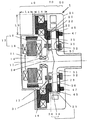
図1は、液体を送るための円板状のインペラ23を設けたポンプ部20および回転駆動力をポンプ部20に伝達するモータロータ15と磁気軸受用電磁石31とをインペラ23に対して同一方向に配置したアクチュエータ部40を備えた磁気浮上型ポンプ1であって、
磁気軸受用電磁石31と円板状インペラ23の両端面の一方の面(以下、アクチュエータ部方向インペラ端面という)に磁気軸受用電磁石31に対向して設けた電磁石対向軟質磁性部材26(第1の強磁性体)との吸引力および円板状インペラの両端面の他方の面すなわちケーシング部50方向のインペラ23の端面(以下、ケーシング部方向インペラ端面という)に設けたインペラ側強磁性体51(第2の強磁性体)とインペラ側強磁性体51(第2の強磁性体)に対向させてインペラ23をケーシング部50方向に吸引するケーシング側強磁性体52(第3の強磁性体)の吸引力および回転駆動手段で発生するインペラへの作用力(図1ではインペラ側永久磁石24とロータ側永久磁石14間の吸引力)およびその他のインペラに加わる外乱が釣り合うように磁気軸受用電磁石31に流れる電流を制御してインペラを磁気浮上させ、
インペラ側強磁性体51(第2の強磁性体)とケーシング側強磁性体52(第3の強磁性体)との対向面形状を異なるようにして磁気軸受用電磁石31の必要最大吸引力f2を小さくするようにして、磁気軸受用電磁石長さL5を短くした磁気浮上ポンプ1である。
FIG. 1 shows a
An electromagnet-facing soft magnetic member 26 (first magnet) provided on one surface of the both end surfaces of the
The required maximum attractive force f2 of the
図1に示す本発明の磁気浮上ポンプ1は、図12と比較して、インペラ側強磁性体51(第2の強磁性体)とケーシング側強磁性体52(第3の強磁性体)との対向面形状を異なるようにすることによって、磁気軸受用電磁石31の図12の必要最大吸引力をf1からf2に小さくして、磁気軸受用電磁石長さを図12のL4からL5に短くして磁気浮上ポンプ1をコンパクトにしている。
The
実施態様1に係る発明は、図1に示すように、液体を送るための円板状のインペラ23を設けたポンプ部20および回転駆動力をインペラ23に伝達するモータロータ15と、インペラ23に対し吸引力を発生する磁気軸受用電磁石31とをインペラ23に対して同一方向に配置したアクチュエータ部40を備えた磁気浮上型ポンプ1であって、
アクチュエータ部方向インペラ端面に磁気軸受用電磁石31に対向して電磁石対向軟質磁性部材26(第1の強磁性体)を設け、
ケーシング部方向インペラ端面にインペラ側強磁性体51(第2の強磁性体)を設け、
インペラ側強磁性体51(第2の強磁性体)に対向させてインペラ23をケーシング部50方向に吸引するケーシング側強磁性体52(第3の強磁性体)を設け、
(1)「磁気軸受用電磁石31と電磁石対向軟質磁性部材26(第1の強磁性体)との吸引力」および(2)「インペラ側強磁性体51(第2の強磁性体)とケーシング側強磁性体52(第3の強磁性体)との吸引力」および(3)「回転駆動手段で発生するインペラ23への作用力(図1ではインペラ側永久磁石24とロータ側永久磁石14間の吸引力)」および(4)「インペラに加わる外乱」が釣り合うように磁気軸受用電磁石31に流れる電流を制御してインペラを磁気浮上させ、
インペラ側強磁性体51(第2の強磁性体)とケーシング側強磁性体52(第3の強磁性体)との対向面形状を異なるようにして磁気軸受用電磁石31の必要最大吸引力f2を小さく抑えて、磁気軸受用電磁石長さL5を短くした磁気浮上ポンプ1である。
As shown in FIG. 1, the invention according to
An electromagnet-facing soft magnetic member 26 (first ferromagnetic body) is provided on the end surface of the impeller in the actuator portion so as to face the
Impeller side ferromagnetic body 51 (second ferromagnetic body) is provided on the impeller end surface in the casing part direction,
A casing-side ferromagnet 52 (third ferromagnet) that attracts the
(1) “Attracting force between
The required maximum attractive force f2 of the
実施態様2に係る発明は、図3ないし図10に示すように、実施態様1に記載のインペラ側強磁性体51(第2の強磁性体)またはケーシング側強磁性体52(第3の強磁性体)がリング形状を有する磁気浮上型ポンプである。
As shown in FIGS. 3 to 10, the invention according to
実施態様3に係る発明は、図7ないし図10に示すように、実施態様1ないし実施態様2に記載のインペラ側強磁性体51(第2の強磁性体)またはケーシング側強磁性体52(第3の強磁性体)が周方向に配置される複数の強磁性体から形成される磁気浮上型ポンプである。 As shown in FIGS. 7 to 10, the invention according to the third embodiment includes an impeller side ferromagnetic body 51 (second ferromagnetic body) or a casing side ferromagnetic body 52 (described in the first to second embodiments). The third ferromagnet is a magnetic levitation pump formed of a plurality of ferromagnets arranged in the circumferential direction.
実施態様4に係る発明は、図3または図5または図7ないし図10のいずれかに示すように、実施態様1ないし実施態様3に記載のインペラ側強磁性体51(第2の強磁性体)の概略内接円の直径が、ケーシング側強磁性体52(第3の強磁性体)の概略内接円の直径よりも大きくした磁気浮上型ポンプである。
As shown in FIG. 3 or FIG. 5 or FIG. 7 to FIG. 10, the invention according to
実施態様5に係る発明は、図4または図6に示すように、実施態様1ないし実施態様3に記載のインペラ側強磁性体51(第2の強磁性体)の概略内接円の直径が、ケーシング側強磁性体52(第3の強磁性体)の概略内接円の直径よりも小さくした磁気浮上型ポンプである。
In the invention according to
実施態様6に係る発明は、図4または図5に示すように、実施態様1ないし実施態様3に記載のインペラ側強磁性体51(第2の強磁性体)の概略外接円の直径が、ケーシング側強磁性体52(第3の強磁性体)の概略外接円の直径よりも大きくした磁気浮上型ポンプである。
In the invention according to
実施態様7に係る発明は、図3または図6ないし図10のいずれかに示すように、実施態様1ないし実施態様3に記載のインペラ側強磁性体51(第2の強磁性体)の概略外接円の直径が、ケーシング側強磁性体52(第3の強磁性体)の概略外接円の直径よりも小さくした磁気浮上型ポンプである。
The invention according to
実施態様8に係る発明は、実施態様1ないし実施態様7に記載のインペラ側強磁性体51(第2の強磁性体)を永久磁石とし、またはケーシング側強磁性体52(第3の強磁性体)を永久磁石とした磁気浮上型ポンプである。 In the invention according to the eighth embodiment, the impeller-side ferromagnetic material 51 (second ferromagnetic material) according to the first to seventh embodiments is used as a permanent magnet, or the casing-side ferromagnetic material 52 (third ferromagnetic material). This is a magnetic levitation pump with a body) as a permanent magnet.
実施態様9に係る発明は、図13に示すように、実施態様1ないし実施態様8に記載のケーシング側強磁性体(第3の強磁性体)に対してインペラ23に対向しない側に強磁性体(第4の強磁性体)53を配置してポンプ外部への漏れ磁束を抑制した磁気浮上型ポンプである。
As shown in FIG. 13, the invention according to Embodiment 9 is ferromagnetic on the side that does not face the
実施態様10に係る発明は、図1に示すように実施態様1ないし実施態様9に記載のインペラ23方向のロータ12の端面にロータ側永久磁石14(第1の永久磁石)を配置するとともに、これに対向させてインペラ23の端面にインペラ側永久磁石24(第2の永久磁石)を配置して、ロータ側永久磁石14とインペラ側永久磁石24とによって磁気カップリングを形成し、インペラ側永久磁石24(第2の永久磁石)を回転させてインペラ23を回転駆動する磁気浮上型ポンプである。
In the invention according to the tenth embodiment, as shown in FIG. 1, the rotor-side permanent magnet 14 (first permanent magnet) is disposed on the end surface of the rotor 12 in the direction of the
実施態様11に係る発明は、実施態様1ないし実施態様10に記載の血液ポンプとして使用する磁気浮上型ポンプである。
The invention according to Embodiment 11 is a magnetic levitation pump used as the blood pump according to
[本発明(図1の説明)] 図1は、従来技術2と同様に、モータ13と磁気軸受用電磁石31とを同じ側の空間に配置した磁気浮上型ポンプである。図1を参照して、本発明の磁気浮上型ポンプについて説明する。図12と同様の機能には同一符号を付して説明を省略する。
[Invention (Description of FIG. 1)] Like FIG. 1, FIG. 1 shows a magnetic levitation pump in which a
図1の本発明の磁気浮上型ポンプ1は、前述した図12に示した従来技術2と同様に、液体を送るための円板状のインペラ23を設けたポンプ部20、およびインペラ23を回転させるためのモータ13とインペラ23に対し吸引力を与える磁気軸受用電磁石31とをインペラ23に対して同一方向に配置したアクチュエータ部40およびインペラ23の浮上位置を測定する位置センサ47を配したケーシング部50を備えている。
The
本発明の磁気浮上型ポンプ1は、上記の構成によって、磁気軸受用電磁石31とアクチュエータ部方向インペラ端面に磁気軸受用電磁石31に対向して設けた電磁石対向軟質磁性部材26(第1の強磁性体)との吸引力およびケーシング部方向インペラ端面に設けたインペラ側強磁性体51(第2の強磁性体)とインペラ側強磁性体51(第2の強磁性体)に対向させてインペラ23をケーシング部50方向に吸引するケーシング側強磁性体52(第3の強磁性体)の吸引力および回転駆動手段で発生するインペラへの作用力(図1ではインペラ側永久磁石24とロータ側永久磁石14間の吸引力)およびインペラに加わる外乱が釣り合うように磁気軸受用電磁石31に流れる電流を制御してインペラを磁気浮上させる。
The
本発明の磁気浮上型ポンプ1は、従来技術1および従来技術2と異なり、インペラ側強磁性体51(第2の強磁性体)とケーシング側強磁性体52(第3の強磁性体)との対向面形状を異なるようにして、磁気軸受用電磁石31の必要最大吸引力を従来技術2のf1よりも小さく抑えてf2とすることで、磁気軸受用電磁石長さを従来技術2のL4からL5まで短くすることで、ポンプ外径部軸方向長Laとポンプ外径の直径方向減少幅Lbとの積La×Lbの円筒体に相当する容積をコンパクト化した磁気浮上ポンプ1である。
Unlike the
[図2の説明] 図2は、ポンプ室22内のモータ電磁石・インペラ間隔壁35から位置センサ・インペラ間隔壁36までのインペラ浮上位置(横軸)とインペラ23への作用力(縦軸)との関係を示すインペラ浮上位置・インペラ作用力特性図である。図2(A)は図12で示した従来の構造におけるインペラ浮上位置・インペラ作用力特性図であり、図2(B)は図1で示した本発明構造におけるインペラ浮上位置・インペラ作用力特性図である。両図におけるインペラ側永久磁石24とロータ側永久磁石14間で発生するアクチュエータ部方向吸引力Fm1とFm2は等しい状態を示している。
[Explanation of FIG. 2] FIG. 2 shows the impeller floating position (horizontal axis) from the motor electromagnet /
横軸は、ポンプ室22内の電磁石・インペラ間隔壁35からインペラ23までの距離を示している。縦軸は、インペラ23への作用力を示している。図では、インペラ23への作用力として、(1)インペラ側強磁性体51(第2の強磁性体)とケーシング側強磁性体52(第3の強磁性体)との間で発生するケーシング部方向吸引力Fcと(2)インペラ側永久磁石24とロータ側永久磁石14との間で発生するアクチュエータ部方向吸引力Fm を示し、さらにこれらの吸引力に抗して各インペラ浮上位置にインペラ23を浮上させるための磁気軸受電磁石31と電磁石対向軟質磁性部材26間で必要となる電磁石吸引力Frを、ケーシング部方向吸引力Fcからアクチュエータ部方向吸引力Fmを加算することによって求め、示した。図2の縦軸では、インペラがケーシング部方向に吸引される吸引力をプラス(+)とし、またインペラに作用するその他の外乱はゼロとしている。
The horizontal axis indicates the distance from the electromagnet /
以下、図2(A)に示した図12の従来の構造のインペラ浮上位置・インペラ作用力特性図と、図2(B)に示した図1の本発明構造のインペラ浮上位置・インペラ作用力特性図とを対比する。 FIG. 2A shows the impeller flying position / impeller acting force characteristic diagram of the conventional structure shown in FIG. 12 and FIG. 2B shows the impeller flying position / impeller acting force of the structure of the present invention shown in FIG. Contrast with the characteristic diagram.
ポンプ室22内でインペラ23の可動範囲はモータ電磁石・インペラ間隔壁35と位置センサ・インペラ間隔壁36によって制限される。電磁石は吸引力のみを発生でき反発力は発生できないため、図12および図1の両構造とも、インペラ23の浮上位置制御を磁気軸受用電磁石31で行うためには、インペラ23のポンプ室22内での可動範囲で、必ず、|ケーシング部方向吸引力Fc|>|アクチュエータ部方向吸引力Fm|となる必要がある。
The movable range of the
図2(B)で示されるように、インペラ側強磁性体51(第2の強磁性体)とこれに対向して置かれたケーシング側強磁性体52(第3の強磁性体)との対向面形状を異なるようにすることによって、図2(A)と比較して、インペラ23の位置変化によるケーシング方向吸引力Fcの増減量を小さくできるので、インペラ位置によって磁気軸受用電磁石31の吸引力Frの変化も小さくでき、磁気軸受用電磁石31の必要最大吸引力f2を図2(A)で示される必要最大吸引力f1より小さく抑えることができる。このように磁気軸受用電磁石31の必要最大吸引力を小さくすることによって磁気軸受用電磁石31の吸引能力を小さくできることから、内部のコイル巻き数を減ずることで磁気軸受用電磁石31の長さを短くし、その吸引能力を下げても問題がないことを意味している。その結果、図1では従来例である図12と比較し、磁気軸受用電磁石31に巻かれるコイルの巻き数を減らすことができた結果、磁気軸受用電磁石31のコンパクト化、ポンプ自体のコンパクト化を実現している。
As shown in FIG. 2B, the impeller-side ferromagnet 51 (second ferromagnet) and the casing-side ferromagnet 52 (third ferromagnet) placed opposite thereto By making the opposed surface shapes different, the amount of increase / decrease in the casing-direction attractive force Fc due to the change in the position of the
図2(B)で示したように、インペラ側強磁性体51(第2の強磁性体)とこれに対向して置かれたケーシング側強磁性体52(第3の強磁性体)とのケーシング部方向吸引力Fcを小にする他の方法として、例えば、(1)インペラ側強磁性体51(第2の強磁性体)を厚くするとともに、ケーシング側強磁性体52(第3の強磁性体)を、このインペラ側強磁性体51(第2の強磁性体)から離して配置する方法、(2)インペラ側強磁性体51(第2の強磁性体)の厚さをそのままにしておいて、ケーシング側強磁性体52(第3の強磁性体)を厚くするとともに、このケーシング側強磁性体52(第3の強磁性体)をインペラ側強磁性体51(第2の強磁性体)から離して配置する方法もあるが、いずれの方法も、ポンプのアキシアル方向(図1では左右方向)の長さが長くなる要因となるために、ポンプをコンパクト化する上で好ましくない。 As shown in FIG. 2B, the impeller side ferromagnetic material 51 (second ferromagnetic material) and the casing side ferromagnetic material 52 (third ferromagnetic material) placed opposite to the impeller side ferromagnetic material 51 (second ferromagnetic material). As another method of reducing the casing portion direction attractive force Fc, for example, (1) while increasing the thickness of the impeller side ferromagnetic material 51 (second ferromagnetic material) and the casing side ferromagnetic material 52 (third strength) A method of arranging the magnetic body) away from the impeller side ferromagnetic body 51 (second ferromagnetic body), and (2) the thickness of the impeller side ferromagnetic body 51 (second ferromagnetic body) is left as it is. The casing side ferromagnetic body 52 (third ferromagnetic body) is thickened, and the casing side ferromagnetic body 52 (third ferromagnetic body) is made to impeller side ferromagnetic body 51 (second strong body). There is also a method of disposing them away from the magnetic body), but both methods are To become a factor length in a direction (in FIG. 1 the left-right direction) becomes longer, which is not preferable in terms of downsizing the pump.
図1では、位置センサ47をケーシング部50に配置したが、図11に示した従来技術1のように磁気軸受用電磁石31と同一側の近傍に配してもよい。また図1では、インペラ23の回転駆動のために磁気カップリングを構成したが、インペラ側永久磁石24に対し、電気的に回転磁界を作用することでインペラを回転駆動させる方法を使用してもよい。
In FIG. 1, the
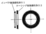
[図3から図10までの説明] 図3から図10は、本発明に係るインペラ側強磁性体51(第2の強磁性体)とケーシング側強磁性体52(第3の強磁性体)との配置およびその形状に関する実施例を示す。これらの図は、この二つの強磁性体のみの関係および形状を示したもので、他のポンプ要素部品、構造などについては関係がない。またこれらの図では、図右側に両強磁性体のアキシアル方向の透視図を示している。 [Explanation of FIGS. 3 to 10] FIGS. 3 to 10 show an impeller side ferromagnetic body 51 (second ferromagnetic body) and a casing side ferromagnetic body 52 (third ferromagnetic body) according to the present invention. And an embodiment related to the arrangement and the shape thereof. These drawings show the relationship and shape of these two ferromagnetic materials only, and are not related to other pump element parts and structures. In these figures, a perspective view in the axial direction of both ferromagnets is shown on the right side of the figure.
図3は、両強磁性体がともにリング形状であって、さらにインペラ側強磁性体51(第2の強磁性体)の内径をケーシング側強磁性体52(第3の強磁性体)よりも大きく、またインペラ側強磁性体51(第2の強磁性体)の外径をケーシング側強磁性体52(第3の強磁性体)よりも小さくした対向面形状が異なる強磁性体を示す図である。この例では、両強磁性体は内径および外径ともに異なるようにしたが、その内径または外径の一方が等しい直径を有していてもよい。また、両強磁性体は互いに対向する方向に吸引力が作用するように材質を選択すればよく、いずれか一方、もしくは両方が永久磁石であればよい。 FIG. 3 shows that both ferromagnets are ring-shaped, and the inner diameter of the impeller-side ferromagnet 51 (second ferromagnet) is larger than that of the casing-side ferromagnet 52 (third ferromagnet). The figure which shows the ferromagnetic material from which the opposing surface shape which is large and made the outer diameter of the impeller side ferromagnetic material 51 (2nd ferromagnetic material) smaller than the casing side ferromagnetic material 52 (3rd ferromagnetic material) differs It is. In this example, both the ferromagnetic bodies have different inner diameters and outer diameters, but either the inner diameter or the outer diameter may have the same diameter. Moreover, what is necessary is just to select a material so that attraction force may act on the both ferromagnets in the direction which mutually opposes, and any one or both should just be a permanent magnet.
図4は、両強磁性体がともにリング形状であって、さらにインペラ側強磁性体51(第2の強磁性体)の内径をケーシング側強磁性体52(第3の強磁性体)よりも小さく、またインペラ側強磁性体51(第2の強磁性体)の外径をケーシング側強磁性体52(第3の強磁性体)よりも大きくした対向面形状が異なる強磁性体を示す図である。この例では、両強磁性体は内径および外径ともに異なるようにしたが、その内径または外径の一方が等しい直径を有していてもよい。また、両強磁性体は互いに対向する方向に吸引力が作用するように材質を選択すればよく、いずれか一方もしくは両方が永久磁石であればよい。 FIG. 4 shows that both ferromagnets are ring-shaped, and the inner diameter of the impeller side ferromagnet 51 (second ferromagnet) is larger than that of the casing side ferromagnet 52 (third ferromagnet). The figure which shows the ferromagnetic material from which the opposing surface shape which is small and made the outer diameter of the impeller side ferromagnetic material 51 (2nd ferromagnetic material) larger than the casing side ferromagnetic material 52 (3rd ferromagnetic material) differs It is. In this example, both the ferromagnetic bodies have different inner diameters and outer diameters, but either the inner diameter or the outer diameter may have the same diameter. Moreover, what is necessary is just to select a material so that attraction force may act on the both ferromagnetic materials in the direction which mutually opposes, and any one or both should just be a permanent magnet.
図5は、両強磁性体がともにリング形状であって、さらにインペラ側強磁性体51(第2の強磁性体)の内径および外径をともにケーシング側強磁性体52(第3の強磁性体)よりも大きくした対向面形状が異なる強磁性体を示す図である。この例では、両強磁性体は内径および外径ともに異なるようにしたが、その一方が等しい直径を有していてもよい。また、両強磁性体は互いに対向する方向に吸引力が作用するように材質を選択すればよく、いずれか一方もしくは両方が永久磁石であればよい。 FIG. 5 shows that both ferromagnets are ring-shaped, and the inner and outer diameters of the impeller side ferromagnet 51 (second ferromagnet) are both the casing side ferromagnet 52 (third ferromagnet). It is a figure which shows the ferromagnetic body from which the opposing surface shape made larger than a body) differs. In this example, both ferromagnets have different inner and outer diameters, but one of them may have the same diameter. Moreover, what is necessary is just to select a material so that attraction force may act on the both ferromagnetic materials in the direction which mutually opposes, and any one or both should just be a permanent magnet.
図6は、両強磁性体がともにリング形状であって、さらにインペラ側強磁性体51(第2の強磁性体)の内径および外径をともにケーシング側強磁性体52(第3の強磁性体)よりも小さくした対向面形状が異なる強磁性体を示す図である。この例では、両強磁性体は内径および外径ともに異なるようにしたが、その一方が等しい直径を有していてもよい。また、両強磁性体は互いに対向する方向に吸引力が作用するように材質を選択すればよく、いずれか一方もしくは両方が永久磁石であればよい。 In FIG. 6, both ferromagnets are ring-shaped, and the inner and outer diameters of the impeller side ferromagnet 51 (second ferromagnet) are both the casing side ferromagnet 52 (third ferromagnet). It is a figure which shows the ferromagnetic body from which the opposing surface shape made smaller than a body) differs. In this example, both ferromagnets have different inner and outer diameters, but one of them may have the same diameter. Moreover, what is necessary is just to select a material so that attraction force may act on the both ferromagnetic materials in the direction which mutually opposes, and any one or both should just be a permanent magnet.
図7は、インペラ側強磁性体51(第2の強磁性体)がリング形状で、ケーシング側強磁性体52(第3の強磁性体)が4個の棒磁石をすべて同じ着磁方向に形成した対向面形状が異なる強磁性体を示す図である。また、このケーシング側強磁性体52(第3の強磁性体)の内接円の直径はインペラ側強磁性体51(第2の強磁性体)の内径よりも小さく、またケーシング側強磁性体52(第3の強磁性体)の外接円の直径はインペラ側強磁性体51(第2の強磁性体)の外径よりも大きい。 FIG. 7 shows that the impeller-side ferromagnet 51 (second ferromagnet) has a ring shape, and the casing-side ferromagnet 52 (third ferromagnet) has all four bar magnets in the same magnetization direction. It is a figure which shows the ferromagnetic material from which the opposing surface shape formed differs. The diameter of the inscribed circle of the casing side ferromagnetic body 52 (third ferromagnetic body) is smaller than the inner diameter of the impeller side ferromagnetic body 51 (second ferromagnetic body), and the casing side ferromagnetic body The diameter of the circumscribed circle of 52 (third ferromagnet) is larger than the outer diameter of impeller side ferromagnet 51 (second ferromagnet).
この例では、両強磁性体の内径または内接円の直径が、両磁性体の外径または外接円の直径をともに異なるようにしたが、その一方が等しい直径を有していてもよい。また、ここでは強磁性体を4個の棒磁石で形成したがその個数に制限はない。また、ケーシング側強磁性体52(第3の強磁性体)は軟質磁性体であってもよい。インペラ側強磁性体51とケーシング側強磁性体は対向する方向に互いに吸引力が作用するように材質を選定すればよく、両方が永久磁石であっても、またインペラ側強磁性体を永久磁石に、さらにケーシング側強磁性体を軟質磁性体で構成してもよい。 In this example, the inner diameters or inscribed circle diameters of both ferromagnets are made different from the outer diameters or inscribed circle diameters of both magnetic bodies, but one of them may have the same diameter. Here, the ferromagnetic material is formed of four bar magnets, but the number is not limited. The casing side ferromagnetic body 52 (third ferromagnetic body) may be a soft magnetic body. The impeller side ferromagnetic body 51 and the casing side ferromagnetic body may be selected from materials so that the attractive force acts in the opposite direction. Even if both are permanent magnets, the impeller side ferromagnetic body is also made of permanent magnets. Furthermore, the casing-side ferromagnetic material may be composed of a soft magnetic material.
図8は、ケーシング側強磁性体52(第3の強磁性体)がリング形状で、インペラ側強磁性体51(第2の強磁性体)がすべて同じ着磁方向である8個の棒磁石で形成した対向面形状が異なる強磁性体を示す図である。また、このインペラ側強磁性体51(第2の強磁性体)の内接円の直径はケーシング側強磁性体52(第3の強磁性体)の内径よりも小さく、またインペラ側強磁性体51(第2の強磁性体)の外接円の直径はケーシング側強磁性体52(第3の強磁性体)の外径よりも大きい。 FIG. 8 shows eight bar magnets in which the casing side ferromagnetic body 52 (third ferromagnetic body) has a ring shape and the impeller side ferromagnetic body 51 (second ferromagnetic body) all have the same magnetization direction. It is a figure which shows the ferromagnetic material from which the opposing surface shape formed in (3) differs. The diameter of the inscribed circle of the impeller side ferromagnetic body 51 (second ferromagnetic body) is smaller than the inner diameter of the casing side ferromagnetic body 52 (third ferromagnetic body), and the impeller side ferromagnetic body The diameter of the circumscribed circle of 51 (second ferromagnetic body) is larger than the outer diameter of the casing side ferromagnetic body 52 (third ferromagnetic body).
この例では、両強磁性体の内径または内接円の直径が、両磁性体の外径または外接円の直径をともに異なるようにしたが、その一方が等しい直径を有していてもよい。また、ここでは強磁性体を8個の棒磁石で形成したがその個数に制限はない。また、ケーシング側強磁性体52(第3の強磁性体)は軟質磁性体であってもよい。また、インペラ側強磁性体51とケーシング側強磁性体は対向する方向に互いに吸引力が作用するように材質を選定すればよく、両方が永久磁石であっても、またインペラ側強磁性体を永久磁石に、さらにケーシング側強磁性体を軟質磁性体で構成してもよい。 In this example, the inner diameters or inscribed circle diameters of both ferromagnets are made different from the outer diameters or inscribed circle diameters of both magnetic bodies, but one of them may have the same diameter. Here, the ferromagnetic material is formed of eight bar magnets, but the number is not limited. The casing side ferromagnetic body 52 (third ferromagnetic body) may be a soft magnetic body. The material for the impeller side ferromagnetic body 51 and the casing side ferromagnetic body may be selected so that an attractive force acts in the opposite direction. Even if both are permanent magnets, the impeller side ferromagnetic body In addition to the permanent magnet, the casing-side ferromagnetic material may be composed of a soft magnetic material.
図9は、インペラ側強磁性体51(第2の強磁性体)がリング形状で、ケーシング側強磁性体52(第3の強磁性体)が同じ方向に着磁した2個の板状磁石で形成した対向面形状が異なる強磁性体を示す図である。 FIG. 9 shows two plate magnets in which the impeller-side ferromagnet 51 (second ferromagnet) is ring-shaped and the casing-side ferromagnet 52 (third ferromagnet) is magnetized in the same direction. It is a figure which shows the ferromagnetic material from which the opposing surface shape formed in (3) differs.
この例では、両強磁性体の内径または内接円の直径が、両磁性体の外径または外接円の直径をともに異なるようにしたが、その一方が等しい直径を有していてもよい。また、ここでは強磁性体を2個の板状磁石で形成したがその個数に制限はない。また、ケーシング側強磁性体52(第3の強磁性体)は軟質磁性体であってもよい。また、インペラ側強磁性体51とケーシング側強磁性体は対向する方向に互いに吸引力が作用するように材質を選定すればよく、両方が永久磁石であっても、またインペラ側強磁性体を永久磁石に、さらにケーシング側強磁性体を軟質磁性体で構成してもよい。 In this example, the inner diameters or inscribed circle diameters of both ferromagnets are made different from the outer diameters or inscribed circle diameters of both magnetic bodies, but one of them may have the same diameter. Here, the ferromagnetic material is formed of two plate magnets, but the number is not limited. The casing side ferromagnetic body 52 (third ferromagnetic body) may be a soft magnetic body. The material for the impeller side ferromagnetic body 51 and the casing side ferromagnetic body may be selected so that an attractive force acts in the opposite direction. Even if both are permanent magnets, the impeller side ferromagnetic body In addition to the permanent magnet, the casing-side ferromagnetic material may be composed of a soft magnetic material.
図10は、ケーシング側強磁性体52(第3の強磁性体)はリング形状で、インペラ側強磁性体51(第2の強磁性体)を同じ方向に着磁した2個の板状磁石で形成した対向面形状が異なる強磁性体を示す図である。 FIG. 10 shows two plate magnets in which the casing side ferromagnetic body 52 (third ferromagnetic body) is ring-shaped and the impeller side ferromagnetic body 51 (second ferromagnetic body) is magnetized in the same direction. It is a figure which shows the ferromagnetic material from which the opposing surface shape formed in (3) differs.
この例では、両強磁性体の内径または内接円の直径が、両磁性体の外径または外接円の直径をともに異なるようにしたが、その一方が等しい直径を有していてもよい。また、ここではインペラ側強磁性体51(第2の強磁性体)2個の板状磁石で形成したがその個数に制限はない。また、インペラ側強磁性体51とケーシング側強磁性体は対向する方向に互いに吸引力が作用するように材質を選定すればよく、両方が永久磁石であっても、またインペラ側強磁性体を永久磁石に、さらにケーシング側強磁性体を軟質磁性材で構成してもよい。 In this example, the inner diameters or inscribed circle diameters of both ferromagnets are made different from the outer diameters or inscribed circle diameters of both magnetic bodies, but one of them may have the same diameter. Further, here, the impeller side ferromagnet 51 (second ferromagnet) is formed by two plate magnets, but the number is not limited. The material for the impeller side ferromagnetic body 51 and the casing side ferromagnetic body may be selected so that an attractive force acts in the opposite direction. Even if both are permanent magnets, the impeller side ferromagnetic body In addition to the permanent magnet, the casing-side ferromagnetic material may be made of a soft magnetic material.
図13は、ケーシング側永久磁石52に対してインペラ23に対向しない側に強磁性体53(第4の強磁性体)を配置させることでポンプ1の外部への漏れ磁束シールド構造を備えた磁気浮上型ポンプである。同図は、図1と比較し、強磁性体53(第4の強磁性体)を置くことで、ケーシング側強磁性体52からのポンプ1の外部への漏れ磁束をシールドでき、またポンプ1の外部からの磁束もシールドできるため、安定したインペラ23の浮上動作が確保できる。ここで、強磁性体53(第4の強磁性体)は軟質磁性材料であっても硬質磁性材料であってもよい。
FIG. 13 shows a magnet having a leakage flux shield structure to the outside of the
また、図1で示したポンプ構造では、位置センサ47はケーシング側永久磁石52の近傍に置いたが、アクチュエータ部40内に配置させてもよい。
In the pump structure shown in FIG. 1, the
今回開示された実施の形態はすべての点で例示であって制限的なものではなく、本発明の範囲は上記説明の範囲ではなくて特許請求の範囲によって示され、特許請求の範囲と均等の意味および範囲内でのすべての変更が含まれる。 The embodiments disclosed herein are illustrative and non-restrictive in every respect, and the scope of the present invention is shown not by the above description but by the scope of claims, and is equivalent to the scope of claims. Includes all changes within the meaning and scope.
この発明によれば、(1)磁気軸受用電磁石31とアクチュエータ部方向のインペラ端面に磁気軸受用電磁石31に対向して設けた電磁石対向軟質磁性部材26(第1の強磁性体)との吸引力および(2)ケーシング部50方向のインペラ23の端面に設けたインペラ側強磁性体51(第2の強磁性体)とこのインペラ側強磁性体51(第2の強磁性体)に対向させてインペラ23をケーシング部50方向に吸引するケーシング側強磁性体52(第3の強磁性体)の吸引力および(3)回転駆動手段で発生するインペラ23への作用力(図1ではインペラ側永久磁石24とロータ側永久磁石14間の吸引力)(4)インペラに加わる外乱が釣り合うように磁気軸受用電磁石31に流れる電流を制御してインペラを磁気浮上させるとともに、インペラ側強磁性体51(第2の強磁性体)とケーシング側強磁性体52(第3の強磁性体)との対向面形状を異なるようにして磁気軸受用電磁石31の必要最大吸引力f2を小さく抑えて、磁気軸受用電磁石長さL5を短くすることができる。
According to the present invention, (1) attraction between the
1 磁気浮上型ポンプ
10 モータ部
11 固定軸
12 ロータ
13 モータ
14 ロータ側永久磁石
15 モータロータ
16 モータステータ
17 モータ軸受
20 ポンプ部
21 ケーシング
22 ポンプ室
23 インペラ
23c 吸入口
24 インペラ側強磁性体
25 ロータ側非磁性部材
26 電磁石対向軟質磁性部材(第1の強磁性体)
27 電磁石・位置センサ対向軟質磁性部材
28 ケーシング側強磁性体
29 インペラ側強磁性体
30 磁気軸受部
31 磁気軸受用電磁石
33 モータ・インペラ間隔壁
34 位置センサ電磁石・インペラ間隔壁
35 電磁石・インペラ間隔壁
36 位置センサ・インペラ間隔壁
45 位置センサ対向軟質磁性部材
40 アクチュエータ部
46 非磁性部材
47 位置センサ
50 ケーシング部
51 インペラ側強磁性体(第2の強磁性体)
52 ケーシング側強磁性体(第3の強磁性体)
53 強磁性体(第4の強磁性体)
L1 従来技術1のポンプ長さ
L2 従来技術2のポンプ長さ
L4 従来技術の磁気軸受用電磁石長さ
L5 本発明の磁気軸受用電磁石長さ
Fc ケーシング部方向吸引力
Fm アクチュエータ部方向吸引力
Fr 電磁石吸引力
f1 図12の構造の必要最大吸引力
f2 図1の構造の必要最大吸引力。
DESCRIPTION OF
27 Electromagnet / position sensor facing soft
52 casing side ferromagnet (third ferromagnet)
53 Ferromagnetic material (fourth ferromagnetic material)
L1 Pump length L2 of
Claims (11)
円板状インペラの回転軸方向の両端面の一方の面に磁気軸受用電磁石に対向して電磁石対向軟質磁性部材を設け、
円板状インペラの回転軸方向の両端面の他方の面にインペラ側強磁性体を設け、
インペラ側強磁性体に対向させてインペラをケーシング部方向に吸引するケーシング側強磁性体を設け、
磁気軸受用電磁石と電磁石対向軟質磁性部材との吸引力およびインペラ側強磁性体とケーシング側強磁性体との吸引力および回転駆動手段で発生するインペラへの作用力およびインペラに加わる外乱が釣り合うように磁気軸受用電磁石に流れる電流を制御してインペラを磁気浮上させ、
インペラが回転軸方向において磁気軸受用電磁石から最も遠ざかった位置にあるときに、ケーシング側強磁性体に対向するインペラ側強磁性体の面の形状を示す第1の形状がインペラ側強磁性体に対向するケーシング側強磁性体の面の形状を示す第2の形状と同じ場合に比べてインペラをケーシング部方向に吸引する力を抑制するように、前記第1および第2の形状が互いに異なるように構成された磁気浮上型ポンプ。 A pump unit provided with a disk-shaped impeller for feeding liquid, and a magnetic bearing unit arranged with an electromagnet for a magnetic bearing and a rotation driving means for transmitting a rotational driving force to the impeller unit facing one surface of the impeller A magnetic levitation pump,
An electromagnet-facing soft magnetic member is provided on one surface of both end surfaces in the rotational axis direction of the disk-shaped impeller so as to oppose the electromagnet for magnetic bearing,
An impeller side ferromagnet is provided on the other surface of both end surfaces in the rotation axis direction of the disk-shaped impeller,
A casing-side ferromagnetic body that attracts the impeller in the direction of the casing portion is provided opposite to the impeller-side ferromagnetic body,
The attraction force between the electromagnet for magnetic bearing and the electromagnet-facing soft magnetic member, the attraction force between the impeller-side ferromagnet and the casing-side ferromagnet, the acting force on the impeller generated by the rotation drive means, and the disturbance applied to the impeller are balanced. To control the current flowing in the electromagnet for magnetic bearings,
When the impeller is located farthest from the electromagnet for magnetic bearing in the rotation axis direction, the first shape indicating the shape of the surface of the impeller-side ferromagnetic material facing the casing-side ferromagnetic material is the impeller-side ferromagnetic material. The first and second shapes are different from each other so as to suppress the force of attracting the impeller toward the casing as compared with the second shape indicating the shape of the surface of the opposing casing side ferromagnetic body. Magnetic levitation pump configured in
Priority Applications (5)
| Application Number | Priority Date | Filing Date | Title |
|---|---|---|---|
| JP2003363607A JP4767488B2 (en) | 2003-10-23 | 2003-10-23 | Magnetic levitation pump |
| AT04025066T ATE347654T1 (en) | 2003-10-23 | 2004-10-21 | MAGNETICALLY SUSPENDED PUMP WITH MAGNETIC BEARING DEVICES |
| US10/968,931 US7467930B2 (en) | 2003-10-23 | 2004-10-21 | Magnetically levitated pump utilizing magnetic bearings |
| DE602004003540T DE602004003540T2 (en) | 2003-10-23 | 2004-10-21 | Magnetically suspended pump with magnetic bearing devices |
| EP04025066A EP1526286B1 (en) | 2003-10-23 | 2004-10-21 | Magnetically levitated pump utilizing magnetic bearings |
Applications Claiming Priority (1)
| Application Number | Priority Date | Filing Date | Title |
|---|---|---|---|
| JP2003363607A JP4767488B2 (en) | 2003-10-23 | 2003-10-23 | Magnetic levitation pump |
Publications (2)
| Publication Number | Publication Date |
|---|---|
| JP2005127222A JP2005127222A (en) | 2005-05-19 |
| JP4767488B2 true JP4767488B2 (en) | 2011-09-07 |
Family
ID=34386530
Family Applications (1)
| Application Number | Title | Priority Date | Filing Date |
|---|---|---|---|
| JP2003363607A Expired - Fee Related JP4767488B2 (en) | 2003-10-23 | 2003-10-23 | Magnetic levitation pump |
Country Status (5)
| Country | Link |
|---|---|
| US (1) | US7467930B2 (en) |
| EP (1) | EP1526286B1 (en) |
| JP (1) | JP4767488B2 (en) |
| AT (1) | ATE347654T1 (en) |
| DE (1) | DE602004003540T2 (en) |
Families Citing this family (49)
| Publication number | Priority date | Publication date | Assignee | Title |
|---|---|---|---|---|
| DE102005052559A1 (en) * | 2005-11-02 | 2007-05-10 | Behr Gmbh & Co. Kg | Adjustable drive for a motor vehicle, in particular for a coolant pump |
| US20070185369A1 (en) * | 2006-02-03 | 2007-08-09 | Mahmood Mirhoseini | Cardiac assist device and method |
| US8431648B2 (en) * | 2006-03-31 | 2013-04-30 | Milliken & Company | Coated substrates and polymer dispersions suitable for use in making the same |
| US8752449B2 (en) | 2007-05-08 | 2014-06-17 | Brooks Automation, Inc. | Substrate transport apparatus with multiple movable arms utilizing a mechanical switch mechanism |
| KR101532060B1 (en) | 2007-06-27 | 2015-06-26 | 브룩스 오토메이션 인코퍼레이티드 | Position feedback for self bearing motor |
| US8823294B2 (en) | 2007-06-27 | 2014-09-02 | Brooks Automation, Inc. | Commutation of an electromagnetic propulsion and guidance system |
| US8283813B2 (en) | 2007-06-27 | 2012-10-09 | Brooks Automation, Inc. | Robot drive with magnetic spindle bearings |
| WO2009003195A1 (en) | 2007-06-27 | 2008-12-31 | Brooks Automation, Inc. | Motor stator with lift capability and reduced cogging characteristics |
| US8129984B2 (en) | 2007-06-27 | 2012-03-06 | Brooks Automation, Inc. | Multiple dimension position sensor |
| US9752615B2 (en) | 2007-06-27 | 2017-09-05 | Brooks Automation, Inc. | Reduced-complexity self-bearing brushless DC motor |
| JP4994971B2 (en) * | 2007-06-29 | 2012-08-08 | アネスト岩田株式会社 | Magnetic bearing, magnetic coupling device, and scroll type fluid machine using the same |
| KR20180014247A (en) * | 2007-07-17 | 2018-02-07 | 브룩스 오토메이션 인코퍼레이티드 | Substrate processing apparatus with motors integral to chamber walls |
| US9044535B2 (en) * | 2007-08-07 | 2015-06-02 | Terumo Cardiovascular Systems Corp. | Extracorporeal blood pump with disposable pump head portion having magnetically levitated impeller |
| CZ300147B6 (en) * | 2007-08-10 | 2009-02-25 | Vysoké ucení technické v Brne | Glandless centrifugal pump with integrated disk-type motor |
| WO2009157408A1 (en) | 2008-06-23 | 2009-12-30 | テルモ株式会社 | Blood pump apparatus |
| WO2010067682A1 (en) | 2008-12-08 | 2010-06-17 | Ntn株式会社 | Centrifugal pump device |
| JP5378010B2 (en) | 2009-03-05 | 2013-12-25 | ソラテック コーポレーション | Centrifugal pump device |
| JP5378012B2 (en) * | 2009-03-06 | 2013-12-25 | ソラテック コーポレーション | Centrifugal pump device |
| JP5378060B2 (en) * | 2009-05-08 | 2013-12-25 | ソラテック コーポレーション | Centrifugal pump device |
| US8770945B2 (en) | 2009-03-06 | 2014-07-08 | Thoratec Corporation | Centrifugal pump apparatus |
| JP5443197B2 (en) * | 2010-02-16 | 2014-03-19 | ソラテック コーポレーション | Centrifugal pump device |
| EP2554191B1 (en) | 2010-03-26 | 2019-05-08 | Thoratec Corporation | Centrifugal blood pump device |
| JP5681403B2 (en) | 2010-07-12 | 2015-03-11 | ソーラテック コーポレイション | Centrifugal pump device |
| JP5577506B2 (en) | 2010-09-14 | 2014-08-27 | ソーラテック コーポレイション | Centrifugal pump device |
| JP5631236B2 (en) * | 2011-02-21 | 2014-11-26 | 三菱電機株式会社 | Pump and heat pump device |
| JP5969979B2 (en) | 2011-03-28 | 2016-08-17 | ソーラテック コーポレイション | Rotation drive device and centrifugal pump device using the same |
| JP4969695B1 (en) | 2011-09-15 | 2012-07-04 | 三菱重工業株式会社 | Drive device for magnetic coupling pump and magnetic coupling pump unit |
| JP6083929B2 (en) | 2012-01-18 | 2017-02-22 | ソーラテック コーポレイション | Centrifugal pump device |
| US20140161651A1 (en) * | 2012-12-11 | 2014-06-12 | Micropump, Inc, a Unit of IDEX Corporation | Compact integrated-drive pumps |
| US9371826B2 (en) | 2013-01-24 | 2016-06-21 | Thoratec Corporation | Impeller position compensation using field oriented control |
| US9556873B2 (en) | 2013-02-27 | 2017-01-31 | Tc1 Llc | Startup sequence for centrifugal pump with levitated impeller |
| US9713663B2 (en) | 2013-04-30 | 2017-07-25 | Tc1 Llc | Cardiac pump with speed adapted for ventricle unloading |
| US10052420B2 (en) | 2013-04-30 | 2018-08-21 | Tc1 Llc | Heart beat identification and pump speed synchronization |
| US9771938B2 (en) | 2014-03-11 | 2017-09-26 | Peopleflo Manufacturing, Inc. | Rotary device having a radial magnetic coupling |
| US9623161B2 (en) | 2014-08-26 | 2017-04-18 | Tc1 Llc | Blood pump and method of suction detection |
| WO2016130846A1 (en) | 2015-02-11 | 2016-08-18 | Thoratec Corporation | Heart beat identification and pump speed synchronization |
| US10166318B2 (en) | 2015-02-12 | 2019-01-01 | Tc1 Llc | System and method for controlling the position of a levitated rotor |
| US10371152B2 (en) | 2015-02-12 | 2019-08-06 | Tc1 Llc | Alternating pump gaps |
| EP3626277A1 (en) | 2015-02-13 | 2020-03-25 | Tc1 Llc | Impeller suspension mechanism for heart pump |
| CN106300722A (en) * | 2015-05-18 | 2017-01-04 | 德昌电机(深圳)有限公司 | Motor and electrodynamic pump |
| US20170016449A1 (en) * | 2015-07-14 | 2017-01-19 | Hamilton Sundstrand Corporation | Axial-flux induction motor pump |
| US10177627B2 (en) | 2015-08-06 | 2019-01-08 | Massachusetts Institute Of Technology | Homopolar, flux-biased hysteresis bearingless motor |
| EP3135933B1 (en) * | 2015-08-25 | 2019-05-01 | ReinHeart GmbH | Active magnetic bearing |
| US9920764B2 (en) | 2015-09-30 | 2018-03-20 | Peopleflo Manufacturing, Inc. | Pump devices |
| US10117983B2 (en) | 2015-11-16 | 2018-11-06 | Tc1 Llc | Pressure/flow characteristic modification of a centrifugal pump in a ventricular assist device |
| US20180245596A1 (en) * | 2016-07-26 | 2018-08-30 | RELIAX MOTORES SA de CV | Integrated electric motor and pump assembly |
| EP3456367A1 (en) * | 2017-09-19 | 2019-03-20 | Abiomed Europe GmbH | Blood pump |
| WO2019125718A1 (en) | 2017-12-22 | 2019-06-27 | Massachusetts Institute Of Technology | Homopolar bearingless slice motors |
| US10947986B2 (en) * | 2018-07-11 | 2021-03-16 | Ch Biomedical (Usa) Inc. | Compact centrifugal pump with magnetically suspended impeller |
Family Cites Families (17)
| Publication number | Priority date | Publication date | Assignee | Title |
|---|---|---|---|---|
| JPS58500593A (en) | 1981-03-18 | 1983-04-21 | ブラム,ギユンタ−,ヴアルタ−,オツト− | Magnetically Suspended and Rotated Impeller Pump Device |
| JPH02241339A (en) * | 1989-03-14 | 1990-09-26 | Hitachi Ltd | Permanent magnet rotor for turbo-charger directly-connecting rotary machine |
| FR2715201B1 (en) * | 1994-01-19 | 1996-02-09 | Inst Nat Polytech Grenoble | Magnetic bearing and assembly comprising a stator part and a rotor part suspended by such a bearing. |
| JPH09170586A (en) * | 1995-12-18 | 1997-06-30 | Nippon Seiko Kk | Water pump |
| WO1999053974A2 (en) | 1998-04-22 | 1999-10-28 | University Of Utah | Implantable centrifugal blood pump with hybrid magnetic bearings |
| US6394769B1 (en) * | 1996-05-03 | 2002-05-28 | Medquest Products, Inc. | Pump having a magnetically suspended rotor with one active control axis |
| AUPO902797A0 (en) * | 1997-09-05 | 1997-10-02 | Cortronix Pty Ltd | A rotary blood pump with hydrodynamically suspended impeller |
| JP3818340B2 (en) * | 1997-09-26 | 2006-09-06 | 株式会社富士通ゼネラル | Permanent magnet motor |
| US6227817B1 (en) | 1999-09-03 | 2001-05-08 | Magnetic Moments, Llc | Magnetically-suspended centrifugal blood pump |
| JP4612925B2 (en) * | 1999-12-27 | 2011-01-12 | Ntn株式会社 | Magnetic levitation pump |
| JP4555437B2 (en) * | 2000-07-10 | 2010-09-29 | Ntn株式会社 | Magnetic levitation pump device |
| JP2002021764A (en) * | 2000-07-11 | 2002-01-23 | Nidec Shibaura Corp | Magnet pump |
| JP4685227B2 (en) * | 2000-10-30 | 2011-05-18 | Ntn株式会社 | Magnetic levitation pump |
| US6626644B2 (en) * | 2000-10-30 | 2003-09-30 | Ntn Corporation | Magnetically levitated pump and controlling circuit |
| JP3996775B2 (en) * | 2002-01-09 | 2007-10-24 | テルモ株式会社 | Centrifugal liquid pump device |
| US7070398B2 (en) * | 2003-09-25 | 2006-07-04 | Medforte Research Foundation | Axial-flow blood pump with magnetically suspended, radially and axially stabilized impeller |
| US7141966B2 (en) * | 2004-07-01 | 2006-11-28 | Denso Corporation | Rotation detecting apparatus |
-
2003
- 2003-10-23 JP JP2003363607A patent/JP4767488B2/en not_active Expired - Fee Related
-
2004
- 2004-10-21 EP EP04025066A patent/EP1526286B1/en not_active Not-in-force
- 2004-10-21 DE DE602004003540T patent/DE602004003540T2/en active Active
- 2004-10-21 US US10/968,931 patent/US7467930B2/en active Active
- 2004-10-21 AT AT04025066T patent/ATE347654T1/en not_active IP Right Cessation
Also Published As
| Publication number | Publication date |
|---|---|
| EP1526286A3 (en) | 2005-05-18 |
| DE602004003540T2 (en) | 2007-04-12 |
| EP1526286A2 (en) | 2005-04-27 |
| EP1526286B1 (en) | 2006-12-06 |
| JP2005127222A (en) | 2005-05-19 |
| DE602004003540D1 (en) | 2007-01-18 |
| US20050089422A1 (en) | 2005-04-28 |
| ATE347654T1 (en) | 2006-12-15 |
| US7467930B2 (en) | 2008-12-23 |
Similar Documents
| Publication | Publication Date | Title |
|---|---|---|
| JP4767488B2 (en) | Magnetic levitation pump | |
| JP4472610B2 (en) | Centrifugal blood pump device | |
| JP5577506B2 (en) | Centrifugal pump device | |
| EP2209186B1 (en) | Magnetically-levitated motor and pump | |
| US6641378B2 (en) | Pump with electrodynamically supported impeller | |
| JP4472612B2 (en) | Centrifugal blood pump device | |
| JP4456857B2 (en) | Centrifugal blood pump device | |
| JP6083929B2 (en) | Centrifugal pump device | |
| WO2011013483A1 (en) | Rotation drive device and centrifugal pump device | |
| KR100701550B1 (en) | Bearingless step motor | |
| JP2010041742A (en) | Axially levitated rotating motor, and turbo-type pump using axially levitated rotating motor | |
| US7598643B2 (en) | Motor with electrodynamically and hydrodynamically supported rotor | |
| JP2009192041A (en) | Thrust force generation device, electromagnetic machine applying thrust force generation device | |
| JP4685227B2 (en) | Magnetic levitation pump | |
| JPH04148095A (en) | Turbo-type pump | |
| CN102163942B (en) | Magnetic suspension motor | |
| JP3930834B2 (en) | Axial type magnetic levitation rotating equipment and centrifugal pump | |
| JPWO2005039019A1 (en) | Actuator | |
| WO2006098500A1 (en) | Magnetic device | |
| JPH01103146A (en) | Motor | |
| JP3357639B2 (en) | Turbo type pump | |
| CN117028416A (en) | Magnetic bearing and pump device | |
| JP2003214374A (en) | Magnetic floatation pump with dynamic bearing | |
| JP2004286176A (en) | Magnetic bearing device | |
| JPH062691A (en) | Clean pump |
Legal Events
| Date | Code | Title | Description |
|---|---|---|---|
| A621 | Written request for application examination |
Free format text: JAPANESE INTERMEDIATE CODE: A621 Effective date: 20061013 |
|
| A131 | Notification of reasons for refusal |
Free format text: JAPANESE INTERMEDIATE CODE: A131 Effective date: 20100202 |
|
| A521 | Request for written amendment filed |
Free format text: JAPANESE INTERMEDIATE CODE: A523 Effective date: 20100331 |
|
| A131 | Notification of reasons for refusal |
Free format text: JAPANESE INTERMEDIATE CODE: A131 Effective date: 20101012 |
|
| A521 | Request for written amendment filed |
Free format text: JAPANESE INTERMEDIATE CODE: A523 Effective date: 20101210 |
|
| TRDD | Decision of grant or rejection written | ||
| A01 | Written decision to grant a patent or to grant a registration (utility model) |
Free format text: JAPANESE INTERMEDIATE CODE: A01 Effective date: 20110524 |
|
| A61 | First payment of annual fees (during grant procedure) |
Free format text: JAPANESE INTERMEDIATE CODE: A61 Effective date: 20110615 |
|
| R150 | Certificate of patent or registration of utility model |
Ref document number: 4767488 Country of ref document: JP Free format text: JAPANESE INTERMEDIATE CODE: R150 Free format text: JAPANESE INTERMEDIATE CODE: R150 |
|
| FPAY | Renewal fee payment (event date is renewal date of database) |
Free format text: PAYMENT UNTIL: 20140624 Year of fee payment: 3 |
|
| S111 | Request for change of ownership or part of ownership |
Free format text: JAPANESE INTERMEDIATE CODE: R313117 |
|
| R350 | Written notification of registration of transfer |
Free format text: JAPANESE INTERMEDIATE CODE: R350 |
|
| R250 | Receipt of annual fees |
Free format text: JAPANESE INTERMEDIATE CODE: R250 |
|
| R250 | Receipt of annual fees |
Free format text: JAPANESE INTERMEDIATE CODE: R250 |
|
| R250 | Receipt of annual fees |
Free format text: JAPANESE INTERMEDIATE CODE: R250 |
|
| R250 | Receipt of annual fees |
Free format text: JAPANESE INTERMEDIATE CODE: R250 |
|
| R250 | Receipt of annual fees |
Free format text: JAPANESE INTERMEDIATE CODE: R250 |
|
| R250 | Receipt of annual fees |
Free format text: JAPANESE INTERMEDIATE CODE: R250 |
|
| R250 | Receipt of annual fees |
Free format text: JAPANESE INTERMEDIATE CODE: R250 |
|
| R250 | Receipt of annual fees |
Free format text: JAPANESE INTERMEDIATE CODE: R250 |
|
| LAPS | Cancellation because of no payment of annual fees |