JP4766661B2 - Image processing method and image processing apparatus - Google Patents
Image processing method and image processing apparatus Download PDFInfo
- Publication number
- JP4766661B2 JP4766661B2 JP2005170043A JP2005170043A JP4766661B2 JP 4766661 B2 JP4766661 B2 JP 4766661B2 JP 2005170043 A JP2005170043 A JP 2005170043A JP 2005170043 A JP2005170043 A JP 2005170043A JP 4766661 B2 JP4766661 B2 JP 4766661B2
- Authority
- JP
- Japan
- Prior art keywords
- image
- noise
- area
- determined
- region
- Prior art date
- Legal status (The legal status is an assumption and is not a legal conclusion. Google has not performed a legal analysis and makes no representation as to the accuracy of the status listed.)
- Expired - Fee Related
Links
Images


Landscapes
- Image Processing (AREA)
- Facsimile Image Signal Circuits (AREA)
- Color Image Communication Systems (AREA)
Description
本発明は、紙原稿をスキャンして取得した画像を領域分割して領域毎にベクトル化する画像処理方法及び画像処理装置に関する。 The present invention relates to an image processing method and an image processing apparatus that divide an image obtained by scanning a paper document and vectorize the image for each region.
近年、情報の電子化が進み、紙文書をそのまま保存するのではなく、電子化して保存したり、その電子データを他装置に送信するシステムが普及してきている。また、その電子化の対象となる文書は、白黒二値の画像だけに留まらず、フルカラー(多値)画像の電子文書へとその対象を広げつつある。 In recent years, the digitization of information has progressed, and systems that do not store paper documents as they are but instead store them electronically or transmit the electronic data to other devices have become widespread. Further, the document to be digitized is not limited to a monochrome binary image but is expanding to a full-color (multi-value) image electronic document.
さらに、対象となる電子文書は、単に紙上の文書をスキャナ等によりスキャンして画像データにしたものだけに留まっていない。例えば、文書画像の領域を分離して、文字領域に対しては文字認識処理を施して文字コード列に変換し、写真領域に対しては輪郭線のベクトルデータに変換する等、電子文書は、より高度な情報へ変換され生成された文書画像を含んできている(例えば、特許文献1参照。)。 Further, the target electronic document is not limited to a document obtained by scanning a document on paper with a scanner or the like into image data. For example, an electronic document is obtained by separating a region of a document image, performing character recognition processing on a character region and converting it into a character code string, converting a photo region into vector data of a contour line, etc. It includes a document image that has been converted into higher information and generated (see, for example, Patent Document 1).
上述したようなベクトル化された画像の中には、フルカラー画像であっても、イラストや図形作成ソフトウェアで作成された原稿をスキャンしてベクトル化した画像等もある。これらの画像は、写真等の自然画像に比べて物体の輪郭が明瞭であり、出現色も限られている等の特徴を有している。尚、以下では、このような画像を「クリップアート画像」と呼ぶ。 Among the vectorized images as described above, even a full-color image includes an image obtained by scanning an original document created by an illustration or graphic creation software and vectorizing it. These images have features such as clear outlines of objects and limited appearance colors compared to natural images such as photographs. Hereinafter, such an image is referred to as a “clip art image”.
また、特許文献2の道路データ生成方法では、まず、フルカラーで入力された写真画像を二値画像に変換する。次いで、二値画像から輪郭線及び中心線を抽出して、得られた線と原画像の色情報をベクトルデータに変換する。尚、ノイズに対する処理は、孤立のノイズを膨張・収縮処理を施して除去することが記載されている。
しかしながら、上述したような従来の処理では、有用領域を間違ってノイズ領域として消去してしまうことがあり、そのような場合は正確な輪郭線を得ることができず、ベクトル化後の画像が画質劣化したものになってしまう。また、ノイズ除去を行わずにノイズ領域をそのまま残して輪郭線をベクトル化した場合には、ベクトルデータ量が膨大となってしまうという問題がある。 However, in the conventional processing as described above, a useful area may be mistakenly deleted as a noise area. In such a case, an accurate contour line cannot be obtained, and the image after vectorization has a picture quality. It will be deteriorated. In addition, when the contour line is vectorized while leaving the noise region without performing noise removal, there is a problem that the amount of vector data becomes enormous.
本発明は、このような事情を考慮してなされたものであり、文書画像から選択された図形領域について、ノイズを削減してデータ量を低減させたベクトルデータを好適に生成することができる(特に、イラストなどのクリップアート画像領域に対して好適なベクトルデータを生成することができる)画像処理方法及び画像処理装置を提供することを目的とする。 The present invention has been made in view of such circumstances, and can suitably generate vector data in which the amount of data is reduced by reducing noise for a graphic region selected from a document image ( In particular, an object of the present invention is to provide an image processing method and an image processing apparatus capable of generating suitable vector data for a clip art image area such as an illustration.
上記課題を解決するために、本発明に係る画像処理方法は、
クラスタリング手段が、ベクトルデータ化処理対象の画像を色特徴の類似度に基づいてクラスタリングすることにより、当該画像において複数のクラスタを生成するクラスタリング工程と、
判定手段が、前記画像において生成された各クラスタに含まれる複数の領域のうち、領域の大きさがノイズ判定閾値よりも小さい領域をノイズとして判定する判定工程と、
除去手段が、前記判定工程でノイズと判定された領域を、当該領域に前記画像上で隣接する他のクラスタの中で、前記色特徴の類似度が最も高いと判断されるクラスタに統合することにより、当該ノイズと判定された領域を除去する除去工程と、
変換手段が、前記除去工程で前記ノイズと判定された領域が除去されたクラスタをベクトルデータに変換する変換工程と
を有することを特徴とする。
In order to solve the above problems, an image processing method according to the present invention includes:
A clustering step of clustering the image to be vectorized on the basis of the similarity of the color features to generate a plurality of clusters in the image ;
A determination step of determining, as noise , a region whose size is smaller than a noise determination threshold among a plurality of regions included in each cluster generated in the image ;
Removal means, said noise and the determined area determination step, in the other clusters adjacent to each other on the image in the area, it is integrated into cluster similarity of the color features are determined and the highest To remove the region determined to be the noise,
The converting means includes a converting step of converting a cluster from which the area determined to be the noise in the removing step is removed into vector data.
本発明によれば、文書画像から選択された図形領域について、ノイズを削減してデータ量を低減させたベクトルデータを好適に生成することができる。 According to the present invention, it is possible to suitably generate vector data in which the amount of data is reduced by reducing noise for a graphic region selected from a document image.
以下、図面を参照して、本発明の一実施形態に係る画像処理装置を用いた画像データのベクトル化処理について、詳細に説明する。 Hereinafter, a vectorization process of image data using an image processing apparatus according to an embodiment of the present invention will be described in detail with reference to the drawings.
<第1の実施形態>
[装置構成]
図1は、本発明の第1の実施形態に係る、領域分割に基づいてベクトル化処理を行う機能を有する画像処理装置の構成を示すブロック図である。図1において、入力部11は、紙原稿等をスキャンすることによってカラー文書画像を入力する。また、領域分離部12は、入力部11で入力されたカラー文書画像を写真領域を含む複数種類の領域に分離する。さらに、クリップアート画像選択部13は、領域分離部12の処理によって分離された領域からクリップアート画像を選択する。
<First Embodiment>
[Device configuration]
FIG. 1 is a block diagram illustrating a configuration of an image processing apparatus having a function of performing vectorization processing based on region division according to the first embodiment of the present invention. In FIG. 1, an
さらにまた、図1において、領域分割部14は、クリップアート画像選択部13によって選択されたクリップアート画像をその色特徴に基づいて複数の領域に分割する。さらにまた、領域統合部15は、分割された複数の領域のうち類似する領域を統合する。さらにまた、ノイズ判定部16は、分割され統合された各領域からノイズ領域を判定する。さらにまた、ノイズ除去部17は、ノイズ判定部16によってノイズ領域と判定された領域を除去する。そして、ベクトル化部18は、領域分割された結果である領域(統合された場合は統合された後の領域、ノイズ除去された場合はノイズ除去後の領域)をそれぞれベクトルデータに変換する。
Furthermore, in FIG. 1, the
図10は、図1に示す画像処理装置を実現した一実施形態であるディジタル複合機(MFP)の主要部構成を示すブロック図である。尚、本実施形態では、画像処理装置として、スキャナ機能やプリンタ機能を有するディジタル複合機(MFP)を用いているが、汎用のスキャナとパーソナルコンピュータとを接続したシステムを当該画像処理装置として用いてもよい。 FIG. 10 is a block diagram showing a main part configuration of a digital multi-function peripheral (MFP) which is an embodiment realizing the image processing apparatus shown in FIG. In this embodiment, a digital multifunction peripheral (MFP) having a scanner function and a printer function is used as the image processing apparatus. However, a system in which a general-purpose scanner and a personal computer are connected is used as the image processing apparatus. Also good.
図10に示すように、MFPは、画像処理装置として機能するコントローラユニット2000を備えている。当該コントローラユニット2000は、画像入力デバイスであるスキャナ2070や画像出力デバイスであるプリンタ2095を接続し、スキャナ2070で原稿画像から読み取られた画像データをプリンタ2095によって印刷出力するコピー機能を実現するための制御を行う。また、コントローラユニット2000は、LAN1006や公衆回線(WAN)1008を介して他装置との間でパターン画像やデバイス情報等の入出力を行うための制御を行う。
As shown in FIG. 10, the MFP includes a
コントローラユニット2000は、図10に示すように、CPU2001を有している。CPU2001は、ROM2003に格納されているブートプログラムによりオペレーションシステム(OS)を立ち上げ、このOS上でHDD(ハードディスクドライブ)2004に格納されているアプリケーションプログラムを実行することによって各種処理を実行する。このCPU2001の作業領域として、RAM2002が用いられる。RAM2002はまた、CPU2001の作業領域だけでなく、画像データを一時記憶するための画像メモリ領域をも提供する。HDD2004は、上記アプリケーションプログラムとともに、画像データを格納する。
As shown in FIG. 10, the
CPU2001には、システムバス2007を介して、ROM2003やRAM2002とともに、操作部I/F(操作部インタフェース)2006、ネットワークI/F(ネットワークインタフェース)2010、モデム2050及びイメージバスI/F(イメージバスインタフェース)2005が接続されている。
Along with the
操作部I/F2006は、タッチパネルを有する操作部2012とのインタフェースであり、操作部2012に表示する画像データを操作部2012に対して出力する。また、操作部I/F2006は、操作部2012においてユーザにより入力された情報をCPU2001に送出する。
An operation unit I /
また、ネットワークI/F2010は、LAN1006に接続され、当該LAN1006を介してLAN1006に接続された各装置との間で情報の入出力を行う。モデム2050は、公衆回線1008に接続し、公衆回線1008を介して他装置との間で情報の入出力を行う。
The network I /
イメージバスI/F2005は、システムバス2007と画像データを高速で転送する画像バス2008を接続し、データ構造を変換するためのバスブリッジである。画像バス2008は、PCIバス又はIEEE1394から構成される。画像バス2008上には、ラスタイメージプロセッサ(RIP)2060、デバイスI/F2020、スキャナ画像処理部2080、プリンタ画像処理部2090、画像回転部2030、サムネイル作成部2035及び画像圧縮部2040が設けられている。
An image bus I / F 2005 is a bus bridge for connecting a
RIP2060は、PDLコードをビットマップイメージに展開するプロセッサである。デバイスI/F2020には、スキャナ2070及びプリンタ2095が接続され、画像データの同期系/非同期系の変換を行う。スキャナ画像処理部2080は、入力画像データに対して補正、加工、編集処理を行う。プリンタ画像処理部2090は、プリント出力画像データに対してプリンタの補正、解像度変換等を行う。画像回転部2030は、画像データの回転を行う。画像圧縮部2040は、多値画像データをJPEGデータに、ニ値画像データをJBIG、MMR、MH等のデータに圧縮するとともに、その伸長処理も行う。
The RIP 2060 is a processor that develops a PDL code into a bitmap image. A
[領域分割に基づいたベクトル化処理の概要]
図2は、本発明の第1の実施形態に係るクリップアート画像の領域分割に基づいたベクトル化処理の詳細について説明するためのフローチャートである。
[Outline of vectorization processing based on area division]
FIG. 2 is a flowchart for explaining details of the vectorization process based on the area division of the clipart image according to the first embodiment of the present invention.
画像処理装置では、まず、入力部11において、紙原稿をスキャン等することによってカラー文書画像データを得る(ステップS11)。次に、領域分離部12において、ステップS11で入力されたカラー文書画像に二値化処理を行って二値の画像データに変換し、この二値の画像データを文字、写真、表等の複数種類の領域に分離する(ステップS12)。尚、この領域分離処理を実現するための一例として、米国特許第5,680,478号公報「Method and Apparatus for character recognition (Shin−YwanWang et aI./Canon K.K.)」に記載の技術を用いることができる。そして、本実施形態における領域分離処理も当該技術を利用することとする。
In the image processing apparatus, first, color document image data is obtained by scanning a paper document in the input unit 11 (step S11). Next, the
次いで、クリップアート画像選択部13において、ステップS12の領域分離工程で分離された領域からクリップアート画像を選択する(ステップS13)。さらに、領域分割部14において、選択された各クリップアート画像の色特徴に基づいてクラスタリング処理を行い、クリップアート画像をクラスタに分割(領域分割)する(ステップS14)。尚、この領域分割処理の詳細については後述する。
Next, the clip art
そして、領域統合部15において、ステップS14の工程で分割されたクラスタを類似度により統合することによって領域統合を行う(ステップS15)。尚、この領域統合処理の詳細については後述する。
Then, the
その後、ノイズ判定部16において領域分割の結果をラベリングして各クラスタの輪郭線を追跡して輪郭線を構成する画素するを計数し(ステップS16)、そして、各ラベル領域の輪郭線を構成する画素数の大きさとある閾値との大きさを比較することにより、当該領域がノイズ領域であるか否かを判定する(ステップS17)。その結果、ラベル領域がある程度小さいものをノイズ領域と判定する(Yes)。一方、ラベル領域がある程度以上の大きさがあるものはノイズ領域と判定せずに(No)、ステップS19に進む。尚、このノイズ判定処理の詳細については後述する。
After that, the result of area division is labeled in the
そして、ノイズ除去部17において、ステップS17で判定されたノイズ領域に含まれたノイズ画素について、隣接する領域間との類似度に基づいて再びクラスタリング処理を行うことによってノイズ除去処理を行い(ステップS18)、ステップS19に進む。尚、このノイズ除去処理の詳細について後述する。
Then, the
ステップS19では、全てのラベル領域に対して処理が終わったかどうか、すなわち、全てのラベル領域の処理が終了したか否かを判定する。その結果、処理対象がまだ存在する場合(No)はステップS17に戻って、当該領域について上述したノイズ領域の判定処理(ステップS17)とノイズ領域の除去処理(ステップS18)を繰り返し実行する。一方、既に全てのラベル領域の処理が終了して処理対象がない場合(Yes)は、ステップS20に進む。 In step S19, it is determined whether or not processing has been completed for all label regions, that is, whether or not processing has been completed for all label regions. As a result, when the processing target still exists (No), the process returns to step S17, and the above-described noise region determination processing (step S17) and noise region removal processing (step S18) are repeatedly executed for the region. On the other hand, when the processing of all the label areas has already been completed and there is no processing target (Yes), the process proceeds to step S20.
そして、ステップS20では、ベクトル化部18において、分割された領域毎に輪郭線と領域内部の色に基づきベクトルデータに変換する。このベクトル化処理を実現する技術としては、例えば、特許第2885999号の二値画像の輪郭線の追跡をし、その座標ベクトルを選択することにより、ベクトル化するものが挙げられる。尚、本実施形態に係るベクトル化処理についても当該技術を利用するものとする。
In step S20, the
[クリップアート画像の選択例]
図3は、本発明の第1の実施形態に係る画像処理において文書画像からクリップアート画像を選択した一例を示す図である。図3では、一文書画像から前述した領域分離法を用いて写真領域31、テキスト領域32、及びクリップアート領域33がそれぞれ矩形領域として分離されている様子を示している。
[Clip art image selection example]
FIG. 3 is a diagram illustrating an example in which a clip art image is selected from a document image in the image processing according to the first embodiment of the present invention. FIG. 3 shows a state in which a
[領域分割処理]
以下、図2に示すフローチャートにおける領域分割処理(ステップS14)について詳細に説明する。図4は、図2に示すフローチャートにおける領域分割処理(ステップS14)を詳細に説明するためのフローチャートである。
[Area division processing]
Hereinafter, the region division processing (step S14) in the flowchart shown in FIG. 2 will be described in detail. FIG. 4 is a flowchart for explaining in detail the area dividing process (step S14) in the flowchart shown in FIG.
まず、ラスタスキャンされたスタートの画素により、最初のクラスタを生成する(ステップS1401)。次いで、次の画素に対して、全てのクラスタ間との類似度を求める(ステップS1402)。類似度が高いほど、画素とクラスタとの特徴が近いと考えられる。類似度の計算処理においては、例えばRGB値の色情報が用いられるが、他のカラー空間の情報、或いは、カラー以外の情報を特徴量としても使ってもよい。 First, the first cluster is generated by the raster-scanned start pixel (step S1401). Next, the similarity between all the clusters is obtained for the next pixel (step S1402). The higher the similarity, the closer the characteristics of the pixel and cluster. In the similarity calculation process, for example, RGB color information is used, but other color space information or information other than color may be used as the feature amount.
そして、一番高い類似度とこの類似度に対応したクラスタ番号を記録して、この類似度を事前に設定された閾値とを比較する(ステップS1403)。その結果、閾値より高い場合(Yes)は、対象画素を記録された当該クラスタに属させる(ステップS1404)。一方、閾値より低い場合(No)は、対象画素に対して新たなクラスタを生成する(ステップS1405)。尚、上記画素に対してクラスタ間との類似度を画素間距離で求めた場合には、類似度が閾値より高い場合とは、当該閾値より画素間距離が小さいということを意味する。 Then, the highest similarity and the cluster number corresponding to this similarity are recorded, and this similarity is compared with a preset threshold (step S1403). If the result is higher than the threshold (Yes), the target pixel belongs to the recorded cluster (step S1404). On the other hand, if it is lower than the threshold (No), a new cluster is generated for the target pixel (step S1405). When the similarity between the clusters with respect to the pixel is obtained by the inter-pixel distance, the case where the similarity is higher than the threshold means that the inter-pixel distance is smaller than the threshold.
ステップS1404又はステップS1405の処理後、全ての画素に対する処理が終わったかどうかを判断する(ステップS1406)。その結果、未処理の画素がまだある場合(No)はステップS1402に戻って、上述した処理を繰り返し実行する。一方、未処理の画素がない場合(Yes)は、領域分割処理(ステップS14)を終了する。 After the process of step S1404 or step S1405, it is determined whether or not the process for all the pixels has been completed (step S1406). As a result, when there are still unprocessed pixels (No), the process returns to step S1402, and the above-described processing is repeatedly executed. On the other hand, if there is no unprocessed pixel (Yes), the area division process (step S14) is terminated.
[領域統合処理]
次に、図2に示すフローチャートにおける領域統合処理(ステップS15)について詳細に説明する。図5は、図2に示すフローチャートにおける領域統合処理(ステップS15)を詳細に説明するためのフローチャートである。
[Area integration processing]
Next, the region integration processing (step S15) in the flowchart shown in FIG. 2 will be described in detail. FIG. 5 is a flowchart for explaining in detail the region integration processing (step S15) in the flowchart shown in FIG.
まず、最終的に分離される領域数の目標値を設定(入力)する(ステップS1501)。本実施形態では、一例として何色くらいに分離するかを目安にして行うものとする。次いで、現在のクラスタの数を計数する(ステップS1502)。そして、計数された現在のクラスタの数と設定された目標値とを比較する(ステップS1503)。 First, a target value for the number of regions to be finally separated is set (input) (step S1501). In the present embodiment, as an example, it is assumed that how many colors are separated as a guide. Next, the number of current clusters is counted (step S1502). Then, the counted current number of clusters is compared with the set target value (step S1503).
その結果、現在のクラスタ数が目標値よりも多い場合(Yes)は、クラスタの統合を行う。本実施形態では、クラスタの統合処理として、まず各クラスタ間の類似度(距離)を計算し(ステップS1504)、その中から一番類似度の高い2つのクラスタ(一番距離の短い2つのクラスタ)を統合処理の対象とし、当該統合処理対象の2つのクラスタを1つのクラスタに統合する(ステップS1505)。 As a result, when the current number of clusters is greater than the target value (Yes), cluster integration is performed. In the present embodiment, as cluster integration processing, first, the similarity (distance) between the clusters is calculated (step S1504), and the two clusters with the highest similarity (two clusters with the shortest distance) are calculated. ) To be integrated, and the two clusters to be integrated are integrated into one cluster (step S1505).
上述したクラスタの統合処理が終った後、再びステップS1502に戻って、統合処理後のクラスタ群に対して上記処理を繰り返し実行する。尚、ステップS1503の比較処理において、現在のクラスタ数が設定された目標値よりも少ない場合(No)は、本領域統合処理(ステップS15)を終了する。 After the above-described cluster integration process is completed, the process returns to step S1502 and the above-described process is repeatedly performed on the cluster group after the integration process. In the comparison process in step S1503, when the current number of clusters is smaller than the set target value (No), the area integration process (step S15) is terminated.
[ノイズ判定処理]
次に、図2に示すフローチャートにおけるノイズ判定処理(ステップS17)について図6を用いて詳細に説明する。図6は、図2に示すフローチャートにおけるノイズ判定処理(ステップS17)について詳細に説明するための図である。
[Noise judgment processing]
Next, the noise determination process (step S17) in the flowchart shown in FIG. 2 will be described in detail with reference to FIG. FIG. 6 is a diagram for explaining in detail the noise determination process (step S17) in the flowchart shown in FIG.
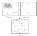
図6において、クラスタ61とクラスタ62は、領域分割処理(ステップS14)及び領域統合処理(ステップS15)後のクラスタから、それぞれ代表として選ばれた2つのクラスタ例である。図6に示すこれらのクラスタ61、62には小さな領域が数多く含まれており、これらをそのままクラスタの輪郭線と内部色情報とをベクトルデータに変換してしまうと、データ量が膨大となって問題となる。そこで、この問題を解決するため、前述したように領域分割の結果をラベリングし(ステップS16)、そして、各ラベル領域の大きさによりノイズ領域であるかどうかを判定することとしている(ステップS17)。その結果、領域63に含まれた各領域はノイズ領域と判定され、それぞれがノイズ除去処理の対象となる。 In FIG. 6, a cluster 61 and a cluster 62 are two examples of clusters selected as representatives from the clusters after the region division processing (step S14) and the region integration processing (step S15). These clusters 61 and 62 shown in FIG. 6 contain many small areas, and if these are converted as they are into the vector data of the contour lines of the clusters and the internal color information, the amount of data becomes enormous. It becomes a problem. Therefore, in order to solve this problem, the result of area division is labeled as described above (step S16), and it is determined whether the area is a noise area based on the size of each label area (step S17). . As a result, each area included in the area 63 is determined as a noise area, and each area is a target of noise removal processing.
[ノイズ除去処理]
次に、図2に示すフローチャートにおけるノイズの除去処理(ステップS18)について詳細に説明する。図7は、図2に示すフローチャートにおけるノイズ除去処理(ステップS18)を詳細に説明するためのフローチャートである。ノイズ除去処理では、ノイズ判定処理(ステップS17)において判定されたノイズ領域をノイズ除去処理対象として、ノイズ領域に含まれたノイズ画素毎に除去処理を行う。
[Noise removal processing]
Next, the noise removal process (step S18) in the flowchart shown in FIG. 2 will be described in detail. FIG. 7 is a flowchart for explaining in detail the noise removal processing (step S18) in the flowchart shown in FIG. In the noise removal process, the noise area determined in the noise determination process (step S17) is set as a noise removal process target, and the removal process is performed for each noise pixel included in the noise area.
そこで、まず、ノイズ画素と各隣接クラスタ間の類似度(例えば、ノイズ画素と隣接領域との距離)を計算する(ステップS1801)。次いで、ノイズ画素を計算された類似度から一番類似度の高いクラスタに属させて(類似度の高い隣接クラスタに統合)、ノイズ画素の属する領域を更新する(ステップS1802)。そして、このノイズ領域に未処理のノイズ画素が存在しているかどうかを判断する(ステップS1803)。 Therefore, first, the similarity between the noise pixel and each adjacent cluster (for example, the distance between the noise pixel and the adjacent region) is calculated (step S1801). Next, the noise pixel is assigned to the cluster having the highest similarity from the calculated similarity (integrated with the adjacent cluster having the highest similarity), and the region to which the noise pixel belongs is updated (step S1802). Then, it is determined whether or not an unprocessed noise pixel exists in this noise region (step S1803).
その結果、未処理の画素がある場合(Yes)はステップS1801に戻って、上記処理を繰り返し実行する。一方、未処理の画素がない場合(No)は、このノイズ領域のノイズ除去処理を終了する。 As a result, when there is an unprocessed pixel (Yes), the process returns to step S1801 to repeat the above process. On the other hand, when there is no unprocessed pixel (No), the noise removal processing of this noise region is finished.
[クリップアート画像の領域分割に基づいたベクトル化の一例]
図8は、本発明の一実施形態によるクリップアート画像の領域分割に基づいたベクトル化の一例を示す図である。図8において、81は領域分割されるクリップアート画像である。また、82は領域分割結果の一例を示す。すなわち、クリップアート画像81は、前述した領域分割、領域統合、ノイズ判定、ノイズ除去の一連の処理により、例えば、分割したい領域数の目標値が16と設定された場合は、領域分割結果82に示す16個のクラスタから成るクラスタ群に分割される。
[Example of vectorization based on segmentation of clip art image]
FIG. 8 is a diagram illustrating an example of vectorization based on region division of a clip art image according to an embodiment of the present invention. In FIG. 8, 81 is a clip art image divided into regions.
ベクトル化処理に必要なクラスタの輪郭と内部色情報の例としては、図8では、クラスタ83、輪郭線84、及び内部色情報85が示されている。領域分割結果82を上記情報に基づいてベクトルデータに変換された結果がベクトル画像86である。ベクトル画像86のファイルサイズは24Kバイトであり、元のクリップアート画像81のファイルサイズが2739Kバイトであるので、ベクトル化によって1/100以下のサイズに減ることになる。また、ベクトル画像86の各クラスタ82を部品として、各クラスタの内部色の塗り潰し等の処理を行うこともできる。
As examples of cluster outlines and internal color information necessary for vectorization processing, FIG. 8 shows a cluster 83, outline 84, and
以上説明したように、本実施形態によれば、ラベリング処理により判定されたノイズ領域を再クラスタリング処理することで、ノイズを効果良く除去することができる。また、ノイズ除去された領域分割の結果をベクトル化することで、データ量を減らすことができる。 As described above, according to the present embodiment, noise can be effectively removed by re-clustering the noise region determined by the labeling process. Also, the amount of data can be reduced by vectorizing the result of the area division from which noise is removed.
<第2の実施形態>
以下、本発明に係る第2実施形態について説明する。
<Second Embodiment>
Hereinafter, a second embodiment according to the present invention will be described.
前述した第1実施形態においては、ラベリング処理後にラベル領域の大きさによりノイズ領域であるかどうかを判定する例を示した。第2実施形態においては、画像の有用な情報が除去されるのを防ぐため、ラベル領域の大きさによりノイズ領域の判定後、さらに他の情報を利用してノイズ領域であるかどうかを判定する例について、図9を参照して説明する。尚、第2の実施形態における領域分割に基づいてベクトル化処理を行う機能を有する画像処理装置の構成について前述した第1の実施形態に係る画像処理装置と同様である。 In the first embodiment described above, an example has been described in which it is determined whether or not the area is a noise area based on the size of the label area after the labeling process. In the second embodiment, in order to prevent useful information from being removed from the image, after determining the noise area based on the size of the label area, it is further determined whether the area is a noise area using other information. An example will be described with reference to FIG. Note that the configuration of the image processing apparatus having a function of performing vectorization processing based on region division in the second embodiment is the same as that of the image processing apparatus according to the first embodiment described above.
図9は、本発明の第2の実施形態に係るクリップアート画像の領域分割に基づいたベクトル化処理の詳細について説明するためのフローチャートである。図9のフローチャートにおいて、ステップS1701とステップS1702は第2の実施形態におけるノイズ領域の判定部分であり、他のステップは前述した第1の実施形態と同じである。 FIG. 9 is a flowchart for explaining details of the vectorization process based on the area division of the clipart image according to the second embodiment of the present invention. In the flowchart of FIG. 9, steps S1701 and S1702 are noise region determination portions in the second embodiment, and other steps are the same as those in the first embodiment described above.
まず、ステップS1701では、ラベル領域の大きさによりノイズ領域の候補であるかどうかを判定する。その結果、ラベル領域が小さくなければ(No)、ノイズ領域ではないと判定してステップS19の処理に遷移する。一方、ラベル領域が小さいと判定された場合(Yes)は、ノイズ領域候補として記録して、ステップS1702の処理に遷移する。 First, in step S1701, it is determined whether or not it is a noise area candidate based on the size of the label area. As a result, if the label area is not small (No), it is determined that the label area is not a noise area, and the process proceeds to step S19. On the other hand, if it is determined that the label area is small (Yes), it is recorded as a noise area candidate, and the process proceeds to step S1702.
次に、ステップS1702では、ステップS1701で記録されたノイズ領域を、周囲にエッジがあるかによって確実にノイズ領域であるかどうかを判定する。その結果、ノイズ領域候補の周囲にエッジ画素がある場合(Yes)は、ノイズ領域であると判定し、ステップS18のノイズ除去処理に遷移する。一方、ノイズ領域候補の周囲に強いエッジ画素がない場合(No)は、ノイズ領域ではないと判定し、ステップS19の処理に遷移する。尚、エッジ画素とは、隣接画素から色や輝度が大きく変化する画素を示すものとし、例えば、ソベルフィルタを用いることによりエッジか否か判定することができる。ここでは、エッジの周囲にはノイズが生じやすいというスキャナの特性やJPEG圧縮等の特性に着目して、ノイズか否か判断している。 Next, in step S1702, it is determined whether the noise area recorded in step S1701 is a noise area depending on whether there is an edge around it. As a result, when there is an edge pixel around the noise area candidate (Yes), it is determined that the area is a noise area, and the process proceeds to the noise removal process in step S18. On the other hand, when there is no strong edge pixel around the noise area candidate (No), it is determined that the area is not a noise area, and the process proceeds to step S19. Note that an edge pixel indicates a pixel whose color or luminance changes greatly from an adjacent pixel. For example, it can be determined whether or not the pixel is an edge by using a Sobel filter. Here, it is determined whether or not the noise is generated by paying attention to the characteristics of the scanner that the noise easily occurs around the edge and the characteristics such as JPEG compression.
また、上記エッジ情報の他にも、ラベル領域の大きさにより判定されたノイズ領域に対して、さらに周囲領域との位置関係によりノイズ領域を判定するようにしてもよい。すなわち、小さいラベル領域に対して、周囲に同じ色の大きい領域がある場合は、確実にノイズ領域として判定する。 In addition to the edge information, the noise region may be determined based on the positional relationship with the surrounding region with respect to the noise region determined based on the size of the label region. That is, if there is a large area of the same color around a small label area, the area is reliably determined as a noise area.
以上第1及び第2の実施形態を示して説明したように、本発明によれば、ノイズ除去を行った領域分割処理により各領域の輪郭を正確に取ることにより、画質の向上が出来、さらに各領域輪郭のベクトル化記述ためのデータ量を削減し、良好な画像の部品を得ることができるようになる。 As described above with reference to the first and second embodiments, according to the present invention, it is possible to improve the image quality by accurately taking the outline of each area by performing the area division process from which noise is removed. It is possible to reduce the amount of data for vectorization description of each region outline and obtain a good image component.
<その他の実施形態>
以上、実施形態例を詳述したが、本発明は、例えば、システム、装置、方法、プログラム若しくは記憶媒体(記録媒体)等としての実施態様をとることが可能であり、具体的には、複数の機器から構成されるシステムに適用しても良いし、また、一つの機器からなる装置に適用しても良い。
<Other embodiments>
Although the embodiments have been described in detail above, the present invention can take embodiments as, for example, a system, an apparatus, a method, a program, or a storage medium (recording medium). The present invention may be applied to a system composed of a single device or an apparatus composed of a single device.
尚、本発明は、前述した実施形態の機能を実現するソフトウェアのプログラム(実施形態では図に示すフローチャートに対応したプログラム)を、システムあるいは装置に直接あるいは遠隔から供給し、そのシステムあるいは装置のコンピュータが該供給されたプログラムコードを読み出して実行することによっても達成される場合を含む。 In the present invention, a software program (in the embodiment, a program corresponding to the flowchart shown in the figure) that realizes the functions of the above-described embodiment is directly or remotely supplied to the system or apparatus, and the computer of the system or apparatus Is also achieved by reading and executing the supplied program code.
従って、本発明の機能処理をコンピュータで実現するために、該コンピュータにインストールされるプログラムコード自体も本発明を実現するものである。つまり、本発明は、本発明の機能処理を実現するためのコンピュータプログラム自体も含まれる。 Accordingly, since the functions of the present invention are implemented by computer, the program code installed in the computer also implements the present invention. In other words, the present invention includes a computer program itself for realizing the functional processing of the present invention.
その場合、プログラムの機能を有していれば、オブジェクトコード、インタプリタにより実行されるプログラム、OSに供給するスクリプトデータ等の形態であっても良い。 In that case, as long as it has the function of a program, it may be in the form of object code, a program executed by an interpreter, script data supplied to the OS, or the like.
プログラムを供給するための記録媒体としては、例えば、フロッピー(登録商標)ディスク、ハードディスク、光ディスク、光磁気ディスク、MO、CD−ROM、CD−R、CD−RW、磁気テープ、不揮発性のメモリカード、ROM、DVD(DVD−ROM,DVD−R)などがある。 As a recording medium for supplying the program, for example, floppy (registered trademark) disk, hard disk, optical disk, magneto-optical disk, MO, CD-ROM, CD-R, CD-RW, magnetic tape, nonvolatile memory card ROM, DVD (DVD-ROM, DVD-R) and the like.
その他、プログラムの供給方法としては、クライアントコンピュータのブラウザを用いてインターネットのホームページに接続し、該ホームページから本発明のコンピュータプログラムそのもの、もしくは圧縮され自動インストール機能を含むファイルをハードディスク等の記録媒体にダウンロードすることによっても供給できる。また、本発明のプログラムを構成するプログラムコードを複数のファイルに分割し、それぞれのファイルを異なるホームページからダウンロードすることによっても実現可能である。つまり、本発明の機能処理をコンピュータで実現するためのプログラムファイルを複数のユーザに対してダウンロードさせるWWWサーバも、本発明に含まれるものである。 As another program supply method, a client computer browser is used to connect to an Internet homepage, and the computer program of the present invention itself or a compressed file including an automatic installation function is downloaded from the homepage to a recording medium such as a hard disk. Can also be supplied. It can also be realized by dividing the program code constituting the program of the present invention into a plurality of files and downloading each file from a different homepage. That is, a WWW server that allows a plurality of users to download a program file for realizing the functional processing of the present invention on a computer is also included in the present invention.
また、本発明のプログラムを暗号化してCD−ROM等の記憶媒体に格納してユーザに配布し、所定の条件をクリアしたユーザに対し、インターネットを介してホームページから暗号化を解く鍵情報をダウンロードさせ、その鍵情報を使用することにより暗号化されたプログラムを実行してコンピュータにインストールさせて実現することも可能である。 In addition, the program of the present invention is encrypted, stored in a storage medium such as a CD-ROM, distributed to users, and key information for decryption is downloaded from a homepage via the Internet to users who have cleared predetermined conditions. It is also possible to execute the encrypted program by using the key information and install the program on a computer.
また、コンピュータが、読み出したプログラムを実行することによって、前述した実施形態の機能が実現される他、そのプログラムの指示に基づき、コンピュータ上で稼動しているOSなどが、実際の処理の一部または全部を行い、その処理によっても前述した実施形態の機能が実現され得る。 In addition to the functions of the above-described embodiments being realized by the computer executing the read program, the OS running on the computer based on the instruction of the program is a part of the actual processing. Alternatively, the functions of the above-described embodiment can be realized by performing all of them and performing the processing.
さらに、記録媒体から読み出されたプログラムが、コンピュータに挿入された機能拡張ボードやコンピュータに接続された機能拡張ユニットに備わるメモリに書き込まれた後、そのプログラムの指示に基づき、その機能拡張ボードや機能拡張ユニットに備わるCPUなどが実際の処理の一部または全部を行い、その処理によっても前述した実施形態の機能が実現される。 Furthermore, after the program read from the recording medium is written in a memory provided in a function expansion board inserted into the computer or a function expansion unit connected to the computer, the function expansion board or The CPU or the like provided in the function expansion unit performs part or all of the actual processing, and the functions of the above-described embodiments are realized by the processing.
11 入力部
12 領域分離部
13 クリップアート画像選択部
14 領域分割部
14 領域統合部
16 ノイズ判定部
17 ノイズ除去部
18 ベクトル化部
DESCRIPTION OF
Claims (11)
判定手段が、前記画像において生成された各クラスタに含まれる複数の領域のうち、領域の大きさがノイズ判定閾値よりも小さい領域をノイズとして判定する判定工程と、
除去手段が、前記判定工程でノイズと判定された領域を、当該領域に前記画像上で隣接する他のクラスタの中で、前記色特徴の類似度が最も高いと判断されるクラスタに統合することにより、当該ノイズと判定された領域を除去する除去工程と、
変換手段が、前記除去工程で前記ノイズと判定された領域が除去されたクラスタをベクトルデータに変換する変換工程と
を有することを特徴とする画像処理方法。 A clustering step of clustering the image to be vectorized on the basis of the similarity of the color features to generate a plurality of clusters in the image ;
A determination step of determining, as noise , a region whose size is smaller than a noise determination threshold among a plurality of regions included in each cluster generated in the image ;
Removal means, said noise and the determined area determination step, in the other clusters adjacent to each other on the image in the area, it is integrated into cluster similarity of the color features are determined and the highest To remove the region determined to be the noise,
An image processing method comprising: a conversion step of converting a cluster from which the area determined to be the noise in the removal step is removed into vector data.
ことを特徴とする請求項1に記載の画像処理方法。 In the clustering step, the image to be vectorized is clustered based on the similarity of the color features to generate a plurality of clusters in the image, and the number of the generated clusters is a target value. If the number is larger, the plurality of clusters having similar color characteristics among the plurality of generated clusters are integrated, and the number of clusters is updated until the target value is reached. The image processing method according to claim 1.
前記クラスタリング工程では、前記生成されたクラスタの数が前記目標値に達するまで前記クラスタの更新を行う
ことを特徴とする請求項2に記載の画像処理方法。 The setting means further comprises a setting step of setting the target value of the number of clusters to be generated;
The image processing method according to claim 2, wherein in the clustering step, the clusters are updated until the number of the generated clusters reaches the target value.
ことを特徴とする請求項1に記載の画像処理方法。 In the determination step, if an edge pixel is present around the area where the size of the area is determined to be smaller than the noise determination threshold, the area is determined as noise. The image processing method according to claim 1 .
ことを特徴とする請求項1に記載の画像処理方法。 Wherein in the determination step, relative to the size of the region is determined to be smaller than the noise determination threshold region, further, has a size and of more than the noise judgment threshold have a same color characteristics around the area The image processing method according to claim 1 , wherein the area is determined as noise on condition that another area exists.
選択手段が、前記分割工程で分割された複数種類の領域の中から、色数が所定数より少ない画像領域を選択する選択工程と、を更に備え、
前記ベクトルデータ化処理対象の画像は、前記選択工程で選択された画像領域である
ことを特徴とする請求項1から5までのいずれか1項に記載の画像処理方法。 A dividing step of dividing the document image into a plurality of types of regions;
A selection step further comprising: a selection step of selecting an image region having a number of colors smaller than a predetermined number from a plurality of types of regions divided in the division step;
The image processing method according to any one of claims 1 to 5, wherein the vector data processing target image is an image region selected in the selection step.
ことを特徴とする請求項1に記載の画像処理方法。 The vector data processing target image is an electronic image obtained by reading a document on which an illustration created using an illustration creation application is printed, or an illustration drawn on a paper manuscript. The image processing method according to claim 1, wherein the image processing method is a region formed of a digitized image.
ことを特徴とする請求項1に記載の画像処理方法。 In the determination step, a plurality of regions included in each cluster are determined by performing a labeling process on each cluster, and the size of the region among the plurality of regions determined by the labeling process is The image processing method according to claim 1, wherein an area smaller than a noise determination threshold is determined as the noise.
前記生成された各クラスタに含まれる複数の領域のうち、領域の大きさがノイズ判定閾値よりも小さい領域をノイズとして判定する判定手段と、
前記判定手段でノイズと判定された領域を、当該領域に前記画像上で隣接する他のクラスタの中で、前記色特徴の類似度が最も高いと判断されるクラスタに統合することにより、当該ノイズと判定された領域を除去する除去手段と、
前記除去手段で前記ノイズと判定された領域が除去されたクラスタをベクトルデータに変換する変換手段と
を備えることを特徴とする画像処理装置。 Clustering means for generating a plurality of clusters in the image by clustering the image to be vectorized based on the similarity of the color features;
A determination unit that determines, as noise , a region whose size is smaller than a noise determination threshold among a plurality of regions included in each of the generated clusters;
Said region determined as noise determining means, among other clusters adjacent to each other on the image in the area, by integrating the cluster similarity of the color features are determined and the highest, the noise Removing means for removing the region determined to be,
An image processing apparatus comprising: a conversion unit configured to convert a cluster from which the area determined to be the noise by the removing unit is removed to vector data.
ベクトルデータ化処理対象の画像を色特徴の類似度に基づいてクラスタリングすることにより、当該画像において複数のクラスタを生成するクラスタリング手段、
前記生成された各クラスタに含まれる複数の領域のうち、領域の大きさがノイズ判定閾値よりも小さい領域をノイズとして判定する判定手段、
前記判定手段でノイズと判定された領域を、当該領域に前記画像上で隣接する他のクラスタの中で、前記色特徴の類似度が最も高いと判断されるクラスタに統合することにより、当該ノイズと判定された領域を除去する除去手段、
前記除去手段で前記ノイズと判定された領域が除去されたクラスタをベクトルデータに変換する変換手段、
として機能させるためのプログラム。 Computer
Clustering means for generating a plurality of clusters in the image by clustering the image to be vectorized based on the similarity of the color features,
A determination unit that determines, as noise , a region having a size smaller than a noise determination threshold among a plurality of regions included in each of the generated clusters.
Said region determined as noise determining means, among other clusters adjacent to each other on the image in the area, by integrating the cluster similarity of the color features are determined and the highest, the noise Removing means for removing the region determined to be,
Conversion means for converting the cluster from which the area determined to be the noise by the removal means is removed into vector data;
Program to function as.
Priority Applications (3)
| Application Number | Priority Date | Filing Date | Title |
|---|---|---|---|
| JP2005170043A JP4766661B2 (en) | 2005-06-09 | 2005-06-09 | Image processing method and image processing apparatus |
| US11/444,389 US7623712B2 (en) | 2005-06-09 | 2006-06-01 | Image processing method and apparatus |
| US12/580,005 US7936929B2 (en) | 2005-06-09 | 2009-10-15 | Image processing method and apparatus for removing noise from a document image |
Applications Claiming Priority (1)
| Application Number | Priority Date | Filing Date | Title |
|---|---|---|---|
| JP2005170043A JP4766661B2 (en) | 2005-06-09 | 2005-06-09 | Image processing method and image processing apparatus |
Publications (3)
| Publication Number | Publication Date |
|---|---|
| JP2006344069A JP2006344069A (en) | 2006-12-21 |
| JP2006344069A5 JP2006344069A5 (en) | 2008-07-24 |
| JP4766661B2 true JP4766661B2 (en) | 2011-09-07 |
Family
ID=37640983
Family Applications (1)
| Application Number | Title | Priority Date | Filing Date |
|---|---|---|---|
| JP2005170043A Expired - Fee Related JP4766661B2 (en) | 2005-06-09 | 2005-06-09 | Image processing method and image processing apparatus |
Country Status (1)
| Country | Link |
|---|---|
| JP (1) | JP4766661B2 (en) |
Families Citing this family (21)
| Publication number | Priority date | Publication date | Assignee | Title |
|---|---|---|---|---|
| JP5149690B2 (en) | 2008-05-02 | 2013-02-20 | キヤノン株式会社 | Image processing apparatus, image processing method, and image processing program |
| JP5047051B2 (en) | 2008-05-02 | 2012-10-10 | キヤノン株式会社 | Image processing apparatus and image encoding method |
| JP5180670B2 (en) | 2008-05-07 | 2013-04-10 | キヤノン株式会社 | Image processing apparatus and image processing method |
| JP5028337B2 (en) | 2008-05-30 | 2012-09-19 | キヤノン株式会社 | Image processing apparatus, image processing method, program, and storage medium |
| JP4586891B2 (en) * | 2008-06-10 | 2010-11-24 | コニカミノルタビジネステクノロジーズ株式会社 | Color reduction method, color reduction processing apparatus, image forming apparatus, and computer program |
| JP5302768B2 (en) * | 2008-06-26 | 2013-10-02 | キヤノン株式会社 | Image processing apparatus and image processing method |
| JP5219706B2 (en) | 2008-09-12 | 2013-06-26 | キヤノン株式会社 | Image processing apparatus, image processing method, and image processing program |
| JP5028370B2 (en) | 2008-09-19 | 2012-09-19 | キヤノン株式会社 | Image processing apparatus, image processing method, and image processing program |
| JP5178490B2 (en) | 2008-12-17 | 2013-04-10 | キヤノン株式会社 | Image processing apparatus, image processing method, and computer program |
| JP5153676B2 (en) | 2009-02-10 | 2013-02-27 | キヤノン株式会社 | Image processing apparatus, image processing method, program, and storage medium |
| JP5173898B2 (en) | 2009-03-11 | 2013-04-03 | キヤノン株式会社 | Image processing method, image processing apparatus, and program |
| JP2011013898A (en) * | 2009-07-01 | 2011-01-20 | Canon Inc | Image processing apparatus, image processing method, and program |
| JP5335581B2 (en) | 2009-07-01 | 2013-11-06 | キヤノン株式会社 | Image processing apparatus, image processing method, and program |
| JP5276539B2 (en) | 2009-07-23 | 2013-08-28 | キヤノン株式会社 | Image processing method, image processing apparatus, and program |
| JP5276541B2 (en) | 2009-07-27 | 2013-08-28 | キヤノン株式会社 | Image processing method, image processing apparatus, and program |
| JP5377148B2 (en) | 2009-08-03 | 2013-12-25 | キヤノン株式会社 | Clustering processing method, clustering processing apparatus, and program |
| JP2011216080A (en) | 2010-03-18 | 2011-10-27 | Canon Inc | Image processing apparatus, image processing method, and storage medium |
| JP2011198246A (en) | 2010-03-23 | 2011-10-06 | Canon Inc | Image processing method, image processing apparatus, program, and program storage medium |
| JP5600524B2 (en) | 2010-08-27 | 2014-10-01 | キヤノン株式会社 | Image processing apparatus, image processing method, program, and storage medium |
| JP5843474B2 (en) | 2011-05-09 | 2016-01-13 | キヤノン株式会社 | Image processing apparatus, image processing method, and program |
| JP5801598B2 (en) | 2011-05-09 | 2015-10-28 | キヤノン株式会社 | Image processing apparatus, image processing method, and program |
Family Cites Families (3)
| Publication number | Priority date | Publication date | Assignee | Title |
|---|---|---|---|---|
| JPH07144078A (en) * | 1993-11-25 | 1995-06-06 | Brother Ind Ltd | Embroidery data preparing device |
| JPH1049687A (en) * | 1996-08-01 | 1998-02-20 | Canon Inc | Picture processor and method for the same |
| JP2004246554A (en) * | 2003-02-13 | 2004-09-02 | Zenrin Co Ltd | Road data generation method |
-
2005
- 2005-06-09 JP JP2005170043A patent/JP4766661B2/en not_active Expired - Fee Related
Also Published As
| Publication number | Publication date |
|---|---|
| JP2006344069A (en) | 2006-12-21 |
Similar Documents
| Publication | Publication Date | Title |
|---|---|---|
| JP4766661B2 (en) | Image processing method and image processing apparatus | |
| JP4799246B2 (en) | Image processing method and image processing apparatus | |
| US7623712B2 (en) | Image processing method and apparatus | |
| JP5047051B2 (en) | Image processing apparatus and image encoding method | |
| JP5302768B2 (en) | Image processing apparatus and image processing method | |
| US8244035B2 (en) | Image processing apparatus and control method thereof | |
| JP5111268B2 (en) | Image processing apparatus, image processing method, program thereof, and storage medium | |
| US8396298B2 (en) | Image processing apparatus, image processing method, and storage medium with vectorization process for data from graphic areas | |
| US7545992B2 (en) | Image processing system and image processing method | |
| US7551753B2 (en) | Image processing apparatus and method therefor | |
| US8203748B2 (en) | Image processing apparatus, control method therefor, and program | |
| JP2004265384A (en) | Image processing system, information processing device, control method, computer program, and computer-readable storage medium | |
| JP4189506B2 (en) | Apparatus, method and recording medium for image processing | |
| JP5219706B2 (en) | Image processing apparatus, image processing method, and image processing program | |
| JP2007174270A (en) | Image processing apparatus, image processing method, storage medium, and program | |
| JP4632443B2 (en) | Image processing apparatus, image processing method, and program | |
| JP4739082B2 (en) | Image processing method and image processing apparatus | |
| JP2006025129A (en) | System and method for image processing | |
| JP5178490B2 (en) | Image processing apparatus, image processing method, and computer program | |
| JP2006023944A (en) | Image processing system and image processing method | |
| JP4748789B2 (en) | Image processing method and image processing apparatus | |
| JP2011053901A (en) | Device, system, method and program for providing document image data, and background processing program | |
| JP2009093627A (en) | Document-image-data providing system, document-image-data providing device, information processing device, document-image-data providing method, information processing method, document-image-data providing program, and information processing program | |
| JP2008017213A (en) | Image processing apparatus and its method |
Legal Events
| Date | Code | Title | Description |
|---|---|---|---|
| A521 | Request for written amendment filed |
Free format text: JAPANESE INTERMEDIATE CODE: A523 Effective date: 20080609 |
|
| A621 | Written request for application examination |
Free format text: JAPANESE INTERMEDIATE CODE: A621 Effective date: 20080609 |
|
| A977 | Report on retrieval |
Free format text: JAPANESE INTERMEDIATE CODE: A971007 Effective date: 20110119 |
|
| A131 | Notification of reasons for refusal |
Free format text: JAPANESE INTERMEDIATE CODE: A131 Effective date: 20110124 |
|
| A521 | Request for written amendment filed |
Free format text: JAPANESE INTERMEDIATE CODE: A523 Effective date: 20110318 |
|
| TRDD | Decision of grant or rejection written | ||
| A01 | Written decision to grant a patent or to grant a registration (utility model) |
Free format text: JAPANESE INTERMEDIATE CODE: A01 Effective date: 20110610 |
|
| A01 | Written decision to grant a patent or to grant a registration (utility model) |
Free format text: JAPANESE INTERMEDIATE CODE: A01 |
|
| A61 | First payment of annual fees (during grant procedure) |
Free format text: JAPANESE INTERMEDIATE CODE: A61 Effective date: 20110613 |
|
| R150 | Certificate of patent or registration of utility model |
Ref document number: 4766661 Country of ref document: JP Free format text: JAPANESE INTERMEDIATE CODE: R150 Free format text: JAPANESE INTERMEDIATE CODE: R150 |
|
| FPAY | Renewal fee payment (event date is renewal date of database) |
Free format text: PAYMENT UNTIL: 20140624 Year of fee payment: 3 |
|
| LAPS | Cancellation because of no payment of annual fees |