JP4766085B2 - Tape drive device, recording medium, and recording / reproducing method - Google Patents
Tape drive device, recording medium, and recording / reproducing method Download PDFInfo
- Publication number
- JP4766085B2 JP4766085B2 JP2008200148A JP2008200148A JP4766085B2 JP 4766085 B2 JP4766085 B2 JP 4766085B2 JP 2008200148 A JP2008200148 A JP 2008200148A JP 2008200148 A JP2008200148 A JP 2008200148A JP 4766085 B2 JP4766085 B2 JP 4766085B2
- Authority
- JP
- Japan
- Prior art keywords
- tape
- recording
- information
- magnetic tape
- data
- Prior art date
- Legal status (The legal status is an assumption and is not a legal conclusion. Google has not performed a legal analysis and makes no representation as to the accuracy of the status listed.)
- Expired - Lifetime
Links
Images


Landscapes
- Management Or Editing Of Information On Record Carriers (AREA)
- Signal Processing For Digital Recording And Reproducing (AREA)
Description
本発明は、磁気テープに記録されているデータの保守を目的とするテープドライブ装置、記録媒体、及び記録再生方法に関するものである。 The present invention relates to a tape drive device, a recording medium , and a recording / reproducing method for maintaining data recorded on a magnetic tape.
同一の記録エリアにおいて、一度だけのデータ記録を行うことができるようにされている記録媒体が知られている。このような記録媒体は記録を行った後は追加記録または再生専用の記録媒体として用いられるので、例えばWORM(Write Once Read Many)と呼ばれている。このWORMとしては、例えば光ディスクとされるCD−Rなどが知られており、ディスクの記録面に物理的にビットを形成することによってデータの記録が行われる。したがって、記録されているデータに対して改変を行うことができないので、データの保守性に優れたものとされる。 There is known a recording medium that can perform data recording only once in the same recording area. Since such a recording medium is used as a recording medium dedicated to additional recording or reproduction after recording, it is called, for example, WORM (Write Once Read Many). As this WORM, for example, a CD-R used as an optical disk is known, and data is recorded by physically forming bits on the recording surface of the disk. Therefore, since the recorded data cannot be modified, the data maintainability is excellent.
ところで、最近ではデジタルデータを磁気テープに記録/再生することのできるドライブ装置として、いわゆるテープストリーマドライブが普及してきている。このようなテープストリーマドライブは、記録媒体とされるテープカセットのテープ長にもよるが、例えば数十〜数百ギガバイト程度の膨大な記録容量を有することが可能であり、このため、コンピュータ本体のハードディスク等のメディアに記録されたデータをバックアップするなどの用途に広く利用されている。また、データサイズの大きい画像データ等の保存に利用する場合にも好適とされている。
また、この磁気テープはCD−Rよりも大容量とされるので、記録媒体の全記録容量に対するビットの単価を安くすることができることから、テープカセットを前記したWORMの記録媒体として用いることが考えられている。
Recently, so-called tape streamer drives have become widespread as drive devices capable of recording / reproducing digital data on a magnetic tape. Such a tape streamer drive can have an enormous recording capacity of, for example, several tens to several hundreds of gigabytes, depending on the tape length of a tape cassette used as a recording medium. It is widely used for applications such as backing up data recorded on a medium such as a hard disk. It is also suitable for use in storing image data having a large data size.
Since this magnetic tape has a larger capacity than the CD-R, the unit price of bits for the total recording capacity of the recording medium can be reduced. Therefore, it is considered that the tape cassette is used as the recording medium for the WORM described above. It has been.
しかし、テープカセットはテープドライブ装置に装填された状態で例えば誤操作が行われることによって、磁気テープに記録されているデータが消去されてしまう場合がある。また、記録されているデータを意図的に書き換えることができるので、重要なデータの保守性に優れたものではないという問題がある。 However, the data recorded on the magnetic tape may be erased, for example, when an erroneous operation is performed while the tape cassette is loaded in the tape drive device. Further, since the recorded data can be rewritten intentionally, there is a problem that the maintainability of important data is not excellent.
本発明はこのような問題点を解決するために、テープカセットに収納された磁気テープに情報の記録及び/または再生を行なうことができるテープドライブ手段と、前記磁気テープへの記録及び/または再生を管理するとともに前記テープカセットを識別するための管理情報を記憶するメモリに対して所要の通信処理を行い、前記管理情報の読み出し及び/または書込みを行なうことができるメモリドライブ手段と、前記メモリのユーザが改変することができない読み出し専用の領域から、前記磁気テープに、制約なしの記録再生可能、追加記録または再生のみ可能とする用途を含む前記管理情報の1つである用途識別情報を検出する用途識別情報検出手段と、前記磁気テープには、前記メモリに記録された前記テープカセットを識別する管理情報と同一のものが記録されており、所要の動作コマンドに対して、前記用途識別情報と前記磁気テープの前記メモリに記録された前記テープカセットを識別する管理情報とに基づいて前記磁気テープに対する動作を行う制御手段とを備えてテープドライブ装置を構成する。 In order to solve such problems, the present invention provides a tape drive means capable of recording and / or reproducing information on a magnetic tape stored in a tape cassette, and recording and / or reproducing on the magnetic tape. It performs required communication processing for memory for storing management information for identifying the tape cassette as well as managing and a memory drive means can be read and / or write the management information, the memory From the read-only area that cannot be modified by the user , the use identification information, which is one of the management information including the use that enables recording / reproduction without restriction, only additional recording or reproduction , is detected on the magnetic tape. and application identification information detecting means, the magnetic tape, tube identifies the tape cassette recorded in the memory It is recorded as information of the same and, for the required operation command, with respect to the magnetic tape on the basis of the management information identifying the tape cassette recorded in the memory of the magnetic tape and the application identification information And a control means for performing the operation to constitute a tape drive device.
前記制御手段は、前記用途識別情報に基づいて、前記磁気テープに対するデータの記録及び/または再生を行う。The control means records and / or reproduces data on the magnetic tape based on the use identification information.
また、前記制御手段は、前記用途識別情報が追加記録または再生のみ可能とされ、これに基づいて、前記磁気テープに対する追加記録を行う場合、前記磁気テープにおける最終記録位置が追加記録の開始位置となるように制御する。Further, the control means can only perform additional recording or reproduction of the use identification information, and based on this, when performing additional recording on the magnetic tape, the final recording position on the magnetic tape is the start position of additional recording. Control to be.
また、前記メモリに記憶されている前記テープカセットを識別する管理情報を検出する第一の識別情報検出手段と、前記磁気テープに記憶されている前記テープカセットを識別する管理情報を検出する第二の識別情報検出手段と、前記第一、第二の識別情報検出手段によって検出された二個の識別情報が一致しているか否かを判別する識別情報判別手段と、前記識別情報判別手段の判別結果に基づいて特定の動作のみを実行させることができる制御手段と、を備える。 The second detecting management information identifying a first identification information detection means for detecting the management information identifying the tape cassette stored in the memory, the tape cassette stored in said magnetic tape The identification information detection means, the identification information determination means for determining whether the two pieces of identification information detected by the first and second identification information detection means match, and the identification information determination means Control means capable of executing only a specific operation based on the result.
本発明の磁気テープが収納されたテープカセットと、前記テープカセットに備えられ、前記磁気テープに対する記録または再生を管理するとともに前記テープカセットを識別するための管理情報を記憶するメモリと、を備えた記録媒体は、前記メモリのユーザが改変することができない読み出し専用の領域には、前記テープカセットに対応した用途を示す、管理情報の1つである用途識別情報が記憶されている。 A tape cassette storing the magnetic tape of the present invention; and a memory provided in the tape cassette for managing recording or reproduction on the magnetic tape and storing management information for identifying the tape cassette . In the recording medium, in a read-only area that cannot be altered by the user of the memory, use identification information that is one of management information indicating the use corresponding to the tape cassette is stored.
また、前記メモリ及び前記磁気テープに前記テープカセットの識別情報が記憶されている。The tape cassette identification information is stored in the memory and the magnetic tape.
また、前記用途識別情報は、前記磁気テープに対して追加記録及び/または再生のみ可能とされている。The application identification information can only be additionally recorded and / or reproduced from the magnetic tape.
本発明の記録再生方法は、テープカセットに収容された磁気テープに情報の記録及び/または再生を行なう際に、前記磁気テープへの記録及び/または再生を管理するとともに前記テープカセットを識別するための管理情報を記憶するメモリに対して、所要の通信処理により前記管理情報の読み出し及び/または書込みを行ない、前記メモリのユーザが改変することができない読み出し専用の領域から、前記磁気テープに、制約なしの記録再生可能、追加記録または再生のみ可能、とする用途を含む前記管理情報の1つである用途識別情報を検出し、前記磁気テープには、前記メモリに記録された前記テープカセットを識別する管理情報と同一のものが記録されており、所要の動作コマンドに対して、前記用途識別情報と前記磁気テープの前記メモリに記録された前記テープカセットを識別する管理情報とに基づいて前記磁気テープに対する記録及び/または再生動作を行う。 The recording / reproducing method of the present invention manages the recording and / or reproduction on the magnetic tape and identifies the tape cassette when recording and / or reproducing information on the magnetic tape accommodated in the tape cassette. of the memory for storing the management information, it performs read and / or write the management information by the required communication processing, a read-only area where the user can not modify the memory, in the magnetic tape, the constraint Detecting use identification information, which is one of the management information including the use of recording / playback without recording, enabling only additional recording or playback, and identifying the tape cassette recorded in the memory on the magnetic tape is recorded management information identical to that which, for the required operation command, before the magnetic tape and the application identification information On the basis of the management information identifying the tape cassette recorded in the memory to record and / or reproducing operation on the magnetic tape.
以上、説明したように本発明のテープドライブ装置は、テープカセットに備えられているメモリ(MIC)から用途識別情報を読み出し、この用途識別情報に基づいてテープカセットに対する動作を制御するようにしている。
これにより、例えば記録動作としては、既に磁気テープに記録されているデータに対する上書きや消去を行わずに、記録最終位置からの追加記録のみを行うことができるようになる。したがって、テープドライブ装置によって既存の記録データを改変させないようにすることができる。
また、記録を行う場合に、磁気テープ上に記録データと共に例えばメモリに記憶されているテープカセットのシリアルナンバなどとされる識別情報を記録するようにしているので、テープカセットに対して磁気テープとメモリに共通の情報を持たせることができるようになる。
さらに、用途識別情報に基づいて磁気テープに対して再生動作のみを可能とするようにしているので、記録データの保護を実現することができるようになる。
As described above, the tape drive device of the present invention reads the application identification information from the memory (MIC) provided in the tape cassette, and controls the operation on the tape cassette based on the application identification information. .
Thereby, for example, as a recording operation, it becomes possible to perform only additional recording from the final recording position without overwriting or erasing data already recorded on the magnetic tape. Therefore, the existing recording data can be prevented from being altered by the tape drive device.
Further, when recording, identification information such as a serial number of the tape cassette stored in the memory is recorded together with the recording data on the magnetic tape. The memory can have common information.
Further, since only the reproducing operation can be performed on the magnetic tape based on the application identification information, the recording data can be protected.
また、本発明のテープドライブ装置としては、テープカセットにおいて磁気テープ及びメモリに記録されている、例えばテープカセットのシリアルナンバなどとされる識別情報の比較を行い、この比較結果に基づいて特定の所定の動作を実行することができるようにしている。したがって、磁気テープ、メモリ双方の識別情報が同一のものである場合のみに磁気テープに対する再生や記録を行うことができるようになる。これにより、例えば磁気テープ又はメモリが交換されたテープカセットに対して、記録データの保護を実現することができる。 Further, the tape drive device of the present invention compares identification information recorded on the magnetic tape and memory in the tape cassette, for example, as the serial number of the tape cassette, and based on the comparison result, It is possible to perform the operation. Therefore, reproduction and recording on the magnetic tape can be performed only when the identification information of both the magnetic tape and the memory is the same. Thereby, for example, protection of recorded data can be realized for a tape cassette whose magnetic tape or memory has been replaced.
また、本発明の記録媒体は、メモリ(MIC)にテープカセットの用途を指示する用途識別情報が記憶されている。したがって、装填されたテープドライブ装置に対して当該記録媒体の用途を示すことができ、テープドライブ装置に対して前記用途に対応した動作を実行させるようにすることができるようになる。さらに、前記用途識別情報は前記メモリにおいて読み出し専用とされる領域に記憶されているので、前記用途識別情報の内容を改変することによって記録媒体の用途を改変させないようにすることができる。 In the recording medium of the present invention, use identification information for instructing the use of the tape cassette is stored in the memory (MIC). Therefore, the usage of the recording medium can be indicated to the loaded tape drive device, and the tape drive device can be caused to execute an operation corresponding to the usage. Furthermore, since the use identification information is stored in a read-only area in the memory, the use of the recording medium can be prevented from being changed by changing the contents of the use identification information.
さらに、メモリ及び磁気テープにテープカセットのシリアルナンバなどとされている識別情報が記憶されている。つまり、メモリと磁気テープに共通とされる同一の情報が記憶され、同一のテープカセットに備えられるメモリと磁気テープを対応させることができるようになる。したがって、例えばメモリが他のテープカセットに挿げ替えられた場合、識別情報が一致しなくなる。このような場合、テープドライブ装置では、例えば記録、再生動作に制約を与えることによって、記録データを開示させないようにしたり、または記録データの改変するための消去、上書き動作などを実行させないようにすることが可能になる。 Further, identification information such as a serial number of the tape cassette is stored in the memory and the magnetic tape. That is, the same information common to the memory and the magnetic tape is stored, and the memory and the magnetic tape provided in the same tape cassette can be associated with each other. Therefore, for example, when the memory is replaced with another tape cassette, the identification information does not match. In such a case, in the tape drive device, for example, by restricting the recording / reproducing operation, the recording data is not disclosed, or the erasing / overwriting operation for modifying the recording data is not performed. It becomes possible.
以下、本発明の実施の形態を説明する。
ここで、先に本出願人により不揮発性メモリが設けられたテープカセット及び、このメモリ付きテープカセットに対応してデジタルデータの記録/再生が可能とされるテープドライブ装置(テープストリーマドライブ)についての発明が各種提案されているが、本実施の形態は、本発明をメモリ付きテープカセット及びテープストリーマドライブからなるデータストレージシステムに適用したものとされる。
説明は以下の順序で行う。
1.テープカセットの構成
2.リモートメモリチップの構成
3.テープストリーマドライブの構成
4.磁気テープ上のデータ構成
5.IDエリア
6.リモートメモリチップのデータ構造
7.WORMに対応した動作制御
Embodiments of the present invention will be described below.
Here, a tape cassette previously provided with a non-volatile memory by the present applicant and a tape drive device (tape streamer drive) capable of recording / reproducing digital data corresponding to the tape cassette with the memory. Various inventions have been proposed. In the present embodiment, the present invention is applied to a data storage system including a tape cassette with a memory and a tape streamer drive.
The description will be made in the following order.
1. Structure of
1.テープカセットの構成
先ず、本例のテープストリーマドライブに対応するテープカセットについて図3及び図4を参照して説明する。
図3(a)は、リモートメモリチップが配されたテープカセットの内部構造を概念的に示すものである。この図に示すテープカセット1の内部にはリール2A及び2Bが設けられ、このリール2A及び2B間にテープ幅8mmの磁気テープ3が巻装される。
そして、このテープカセット1には不揮発性メモリ及びその制御回路系等を内蔵したリモートメモリチップ4が設けられている。またこのリモートメモリチップ4は後述するテープストリーマドライブにおけるリモートメモリインターフェース30と無線通信によりデータ伝送を行うことができるものとされ、このためのアンテナ5が設けられている。
詳しくは後述するが、リモートメモリチップ4には、テープカセットごとの製造情報やシリアル番号情報、テープの厚さや長さ、材質、各パーティションごとの記録データの使用履歴等に関連する情報、ユーザ情報等が記憶される。
なお、本明細書では上記リモートメモリチップ4に格納される各種情報は、主として磁気テープ3に対する記録/再生の各種管理のために用いられることから、これらを一括して『管理情報』とも言うことにする。
1. Configuration of Tape Cassette First, a tape cassette corresponding to the tape streamer drive of this example will be described with reference to FIGS.
FIG. 3A conceptually shows the internal structure of the tape cassette in which the remote memory chip is arranged. Inside the
The
As will be described in detail later, the
In the present specification, since various information stored in the
このようにテープカセット筐体内に不揮発性メモリを設け、その不揮発性メモリに管理情報を記憶させ、またこのテープカセットに対応するテープストリーマドライブでは、不揮発性メモリに対する書込/読出のためのインターフェースを備えるようにし、不揮発性メモリに対して磁気テープに対するデータ記録再生に関する管理情報の読出や書込を行うことで、磁気テープ3に対する記録再生動作を効率的に行うことができる。
例えばローディング/アンローディングの際に磁気テープを例えばテープトップまで巻き戻す必要はなく、即ち途中の位置でも、ローディング、及びアンローディング可能とすることができる。またデータの編集なども不揮発性メモリ上での管理情報の書換で実行できる。さらにテープ上でより多数のパーティションを設定し、かつ適切に管理することも容易となる。
As described above, the nonvolatile memory is provided in the tape cassette housing, the management information is stored in the nonvolatile memory, and the tape streamer drive corresponding to the tape cassette has an interface for writing / reading the nonvolatile memory. By providing and reading management information related to data recording / reproducing with respect to the magnetic tape to / from the nonvolatile memory, the recording / reproducing operation with respect to the
For example, it is not necessary to rewind the magnetic tape to, for example, the tape top at the time of loading / unloading, that is, loading and unloading can be performed at an intermediate position. Data editing and the like can also be executed by rewriting management information on the nonvolatile memory. Furthermore, it becomes easy to set a larger number of partitions on the tape and appropriately manage them.
また図3(b)は、接触型メモリ104(不揮発性メモリ)が内蔵されたテープカセット1を示している。
この場合、接触型メモリ104のモジュールからは5個の端子105A、105B、105C、105D、105Eが導出され、それぞれ電源端子、データ入力端子、クロック入力端子、アース端子、予備端子等として構成されている。
この接触型メモリ104内のデータとしては、上記リモートメモリチップ4と同様の管理情報が記憶される。
FIG. 3B shows the
In this case, five
As data in the contact memory 104, management information similar to that of the
なお、以降の説明でリモートメモリチップ4と接触型メモリ104の双方を示す場合は、MIC(Memory In Cassette)ということにする。
In the following description, when both the
図4は、図3(a)又は(b)のテープカセット1の外観例を示すものとされ、筺体全体は上側ケース6a、下側ケース6b、及びガードパネル8からなり、通常の8ミリVTRに用いられるテープカセットの構成と基本的には同様となっている。
FIG. 4 shows an example of the external appearance of the
このテープカセット1の側面のラベル面9の近傍には、端子部106が設けられている。
これは図3(b)の接触型メモリ104を内蔵したタイプのテープカセットにおいて電極端子が配される部位とされるもので、端子ピン106A、106B、106C、106D、106Eが設けられている。そしてこれら端子ピンが、上記図3(b)2に示した各端子105A、105B、105C、105D、105Eとそれぞれ接続されている。すなわち、接触型メモリ104を有するテープカセット1は、テープストリーマドライブとの間で、上記端子ピン106A、106B、106C、106D、106Eを介して物理的に接触してデータ信号等の相互伝送が行われるものとされる。
A
This is a portion where electrode terminals are arranged in the tape cassette of the type incorporating the contact type memory 104 of FIG. 3B, and
一方、図3(a)のように非接触のリモートメモリチップ4を内蔵するタイプでは、当然ながら端子ピンは不要となる。しかしながら外観形状としては図4のようになり、つまり装置に対するテープカセット形状の互換性を保つためにダミーの端子部106が設けられている。
また、図示しないがラベル状に形成された非接触型のリモートメモリチップも知られている。これは、リモートメモリチップが形成されているラベルをテープカセット1及び筐体の所要の位置に貼り付けられたものとされる。これにより、テープカセット1がテープストリーマドライブ10に装填された場合に、リモートメモリチップとテープストリーマドライブのメモリドライブ手段が通信を行うことができる。
On the other hand, in the type in which the non-contact
A non-contact type remote memory chip formed in a label shape is also known although not shown. This is assumed that paste the label to the remote memory chip is formed to a desired position of the
2.リモートメモリチップの構成
リモートメモリチップ4の内部構成を図5に示す。
例えばリモートメモリチップ4は半導体ICとして図5に示すようにパワー回路4a、RF処理部4b、コントローラ4c、EEP−ROM4dを有するものとされる。そして例えばこのようなリモートメモリチップ4がテープカセット1の内部に固定されたプリント基板上にマウントとされ、プリント基板上の銅箔部分でアンテナ5を形成する。
2. Configuration of Remote Memory Chip The internal configuration of the
For example, the
このリモートメモリチップ4は非接触にて外部から電力供給を受ける構成とされる。後述するテープストリーマドライブ10との間の通信は、例えば13MHz帯の搬送波を用いるが、テープストリーマドライブ10からの電波をアンテナ5で受信することで、パワー回路4aが13MHz帯の搬送波を直流電力に変換する。そしてその直流電力を動作電源としてRF処理部4b、コントローラ4c、EEP−ROM4dに供給する。
The
RF処理部4bは受信された情報の復調及び送信する情報の変調を行う。
コントローラ4cはRF処理部4bからの受信信号のデコード、及びデコードされた情報(コマンド)に応じた処理、例えばEEP−ROM4dに対する書込・読出処理などを実行制御する。
即ちリモートメモリチップ4はテープストリーマドライブ10やライブラリ装置50からの電波が受信されることでパワーオン状態となり、コントローラ4cが搬送波に重畳されたコマンドによって指示された処理を実行して不揮発性メモリであるEEP−ROM4dのデータを管理する。
The
The
That is, the
3.テープストリーマドライブの構成
次に図1により、図3(a)に示したリモートメモリチップ4を搭載したテープカセット1に対応するテープストリーマドライブ10の構成について説明する。このテープストリーマドライブ10は、上記テープカセット1の磁気テープ3に対して、ヘリカルスキャン方式により記録/再生を行うようにされている。
この図において回転ドラム11には、例えば2つの記録ヘッド12A、12B及び3つの再生ヘッド13A、13B、13Cが設けられる。
記録ヘッド12A、12Bは互いにアジマス角の異なる2つのギャップが究めて近接して配置される構造となっている。再生ヘッド13A、13B、13Bもそれぞれ所定のアジマス角とされる。
3. Configuration of Tape Streamer Drive Next, the configuration of the
In this figure, the
The recording heads 12A and 12B have a structure in which two gaps having different azimuth angles are arranged close to each other. The reproducing heads 13A, 13B, and 13B are also set to predetermined azimuth angles.
回転ドラム11はドラムモータ14Aにより回転されると共に、テープカセット1から引き出された磁気テープ3が巻き付けられる。また、磁気テープ3は、キャプスタンモータ14B及び図示しないピンチローラにより送られる。また磁気テープ3は上述したようにリール2A,2Bに巻装されているが、リール2A,2Bはそれぞれリールモータ14C、14Dによりそれぞれ順方向及び逆方向に回転される。
ローディングモータ14Eは、図示しないローディング機構を駆動し、磁気テープ3の回転ドラム11へのローディング/アンローディングを実行する。
イジェクトモータ28はテープカセット1の装填機構を駆動するモータであり、挿入されたテープカセット1の着座およびテープカセット1の排出動作を実行させる。
The
The
The
ドラムモータ14A、キャプスタンモータ14B、リールモータ14C、14D、ローディングモータ14E、イジェクトモータ28はそれぞれメカドライバ17からの電力印加により回転駆動される。メカドライバ17はサーボコントローラ16からの制御に基づいて各モータを駆動する。サーボコントローラ16は各モータの回転速度制御を行って通常の記録再生時の走行や高速再生時のテープ走行、早送り、巻き戻し時のテープ走行などを実行させる。
なおEEP−ROM18にはサーボコントローラ16が各モータのサーボ制御に用いる定数等が格納されている。
The
The EEP-
サーボコントローラ16が各モータのサーボ制御を実行するために、ドラムモータ14A、キャプスタンモータ14B、Tリールモータ14C、Sリールモータ14DにはそれぞれFG(周波数発生器)が設けられており、各モータの回転情報が検出できるようにしている。即ちドラムモータ14Aの回転に同期した周波数パルスを発生させるドラムFG29A、キャプスタンモータ14Bの回転に同期した周波数パルスを発生させるキャプスタンFG29B、Tリールモータ14Cの回転に同期した周波数パルスを発生させるTリールFG29C、Sリールモータ14Dの回転に同期した周波数パルスを発生させるSリールFG29Dが形成され、これらの出力(FGパルス)がサーボコントローラ16に供給される。
In order for the
サーボコントローラ16はこれらのFGパルスに基づいて各モータの回転速度を判別することで、各モータの回転動作について目的とする回転速度との誤差を検出し、その誤差分に相当する印加電力制御をメカドライバ17に対して行うことで、閉ループによる回転速度制御を実現することができる。従って、記録/再生時の通常走行や、高速サーチ、早送り、巻き戻しなどの各種動作時に、サーボコントローラ16はそれぞれの動作に応じた目標回転速度により各モータが回転されるように制御を行うことができる。
また、サーボコントローラ16はインターフェースコントローラ/ECCフォーマター22(以下、IF/ECCコントローラという)を介してシステム全体の制御処理を実行するシステムコントローラ15と双方向に接続されている。
The
The
このテープストリーマドライブ10においては、データの入出力にSCSIインターフェイス20が用いられている。例えばデータ記録時にはホストコンピュータ40から、固定長のレコード(record)という伝送データ単位によりSCSIインターフェイス20を介して逐次データが入力され、SCSIバッファコントローラ26を介して圧縮/伸長回路21に供給される。SCSIバッファコントローラ26はSCSIインターフェース20のデータ転送を制御するようにされている。SCSIバッファメモリ27はSCSIインターフェース20の転送速度を得るために、SCSIバッファコントローラ26に対応して備えられるバッファ手段とされる。またSCSIバッファコントローラ26は、後述するリモートメモリインターフェース30に対して所要のコマンドデータを供給するとともに、リモートメモリインターフェース30に対する動作クロックの生成も行う。
なお、このようなテープストリーマドライブシステムにおいては、可変長のデータの集合単位によってホストコンピュータ40よりデータが伝送されるモードも存在する。
The
In such a tape streamer drive system, there is a mode in which data is transmitted from the
圧縮/伸長回路21では、入力されたデータについて必要があれば、所定方式によって圧縮処理を施すようにされる。圧縮方式の一例として、例えばLZ符号による圧縮方式を採用するのであれば、この方式では過去に処理した文字列に対して専用のコードが割り与えられて辞書の形で格納される。そして、以降に入力される文字列と辞書の内容とが比較されて、入力データの文字列が辞書のコードと一致すればこの文字列データを辞書のコードに置き換えるようにしていく。辞書と一致しなかった入力文字列のデータは逐次新たなコードが与えられて辞書に登録されていく。このようにして入力文字列のデータを辞書に登録し、文字列データを辞書のコードに置き換えていくことによりデータ圧縮が行われるようにされる。
The compression /
圧縮/伸長回路21の出力は、IF/ECCコントローラ22に供給されるが、IF/ECCコントローラ22においてはその制御動作によって圧縮/伸長回路21の出力をバッファメモリ23に一旦蓄積する。このバッファメモリ23に蓄積されたデータはIF/ECCコントローラ22の制御によって、最終的にグループ(Group)という磁気テープの40トラック分に相当する固定長の単位としてデータを扱うようにされ、このデータに対してECCフォーマット処理が行われる。
The output of the compression /
ECCフォーマット処理としては、記録データについて誤り訂正コードを付加すると共に、磁気記録に適合するようにデータについて変調処理を行ってRF処理部19に供給する。
RF処理部19では供給された記録データに対して増幅、記録イコライジング等の処理を施して記録信号を生成し、記録ヘッド12A、12Bに供給する。これにより記録ヘッド12A、12Bから磁気テープ3に対するデータの記録が行われることになる。
As the ECC format processing, an error correction code is added to the recording data, and the data is subjected to modulation processing so as to be compatible with magnetic recording and supplied to the
The
また、データ再生動作について簡単に説明すると、磁気テープ3の記録データが再生ヘッド13A、13BによりRF再生信号として読み出され、その再生出力はRF処理部19で再生イコライジング、再生クロック生成、2値化、デコード(例えばビタビ復号)などが行われる。
このようにして読み出された信号はIF/ECCコントローラ22に供給されて、まず誤り訂正処理等が施される。そしてバッファメモリ23に一時蓄積され、所定の時点で読み出されて圧縮/伸長回路21に供給される。
圧縮/伸長回路21では、システムコントローラ15の判断に基づいて、記録時に圧縮/伸長回路21により圧縮が施されたデータであればここでデータ伸長処理を行い、非圧縮データであればデータ伸長処理を行わずにそのままパスして出力される。
圧縮/伸長回路21の出力データはSCSIバッファコントローラ26、SCSIインターフェイス20を介して再生データとしてホストコンピュータ40に出力される。
The data reproduction operation will be briefly described. The recording data of the
The signal read in this way is supplied to the IF /
In the compression /
The output data of the compression /
また、この図にはテープカセット1内のリモートメモリチップ4が示されている。このリモートメモリチップ4に対しては、テープカセット1本体がテープストリーマドライブに装填されることで、リモートメモリインターフェース30を介して非接触状態でシステムコントローラ15とデータの入出力が可能な状態となる。
Further, in this figure, the
このリモートメモリインターフェース30の構成を図2に示す。
データインターフェース31は、システムコントローラ15との間のデータのやりとりを行う。後述するように、リモートメモリチップ4に対するデータ転送は、機器側からのコマンドとそれに対応するリモートメモリチップ4からのアクナレッジという形態で行われるが、システムコントローラ15がリモートメモリチップ4にコマンドを発行する際には、データインターフェース31がSCSIバッファコントローラ26からコマンドデータ及びクロックを受け取る。そしてデータインターフェース31はクロックに基づいてコマンドデータをRFインターフェース32に供給する。またデータインターフェース31はRFインターフェース32に対して搬送波周波数CR(13MHz)を供給する。
The configuration of the
The data interface 31 exchanges data with the
RFインターフェース32には図2に示すようにコマンド(送信データ)WSを振幅変調(100KHz)して搬送波周波数CRに重畳するとともに、その変調信号を増幅してアンテナ33に印加するRF変調/増幅回路32aが形成されている。
このRF変調/増幅回路32aにより、コマンドデータがアンテナ33からテープカセット1内のアンテナ5に対して無線送信される。テープカセット1側では、図5で説明した構成により、コマンドデータをアンテナ5で受信することでパワーオン状態となり、コマンドで指示された内容に応じてコントローラ4cが動作を行う。例えば書込コマンドとともに送信されてきたデータをEEP−ROM4dに書き込む。
As shown in FIG. 2, the
The RF modulation /
また、このようにリモートメモリインターフェース30からコマンドが発せられた際には、リモートメモリチップ4はそれに対応したアクナレッジを発することになる。即ちリモートメモリチップ4のコントローラ4cはアクナレッジとしてのデータをRF処理部4bで変調・増幅させ、アンテナ5から送信出力する。
このようなアクナレッジが送信されてアンテナ33で受信された場合は、その受信信号はRFインターフェース32の整流回路32bで整流された後、コンパレータ32cでデータとして復調される。そしてデータインターフェース31からシステムコントローラ15に供給される。例えばシステムコントローラ15からリモートメモリチップ4に対して読出コマンドを発した場合は、リモートメモリチップ4はそれに応じたアクナレッジとしてのコードとともにEEP−ROM4dから読み出したデータを送信してくる。するとそのアクナレッジコード及び読み出したデータが、リモートメモリインターフェース30で受信復調され、システムコントローラ15に供給される。
When a command is issued from the
When such an acknowledgment is transmitted and received by the
以上のようにテープストリーマドライブ10は、リモートメモリインターフェース30を有することで、テープカセット1内のリモートメモリチップ4に対してアクセスできることになる。
なお、このような非接触でのデータ交換は、データを13MHz帯の搬送波に100KHzの振幅変調で重畳するが、元のデータはパケット化されたデータとなる。
即ちコマンドやアクナレッジとしてのデータに対してヘッダやパリティ、その他必要な情報を付加してパケット化を行い、そのパケットをコード変換してから変調することで、安定したRF信号として送受信できるようにしている。
なお、このような非接触インターフェースを実現する技術は本出願人が先に出願し特許登録された技術として紹介されている(特許第2550931号)。
As described above, the
In such non-contact data exchange, data is superimposed on a 13 MHz band carrier wave with amplitude modulation of 100 KHz, but the original data is packetized data.
In other words, by adding a header, parity, and other necessary information to the command and acknowledge data, packetize it, and then convert the packet after code conversion so that it can be transmitted and received as a stable RF signal. ing.
A technique for realizing such a non-contact interface has been introduced as a technique that was previously filed and registered by the present applicant (Japanese Patent No. 2550931).
図1に示すS−RAM24,フラッシュROM25は、システムコントローラ15が各種処理に用いるデータが記憶される。
例えばフラッシュROM25には制御に用いる定数等が記憶される。またS−RAM24はワークメモリとして用いられたり、リモートメモリチップ4から読み出されたデータ、リモートメモリチップ4に書き込むデータ、テープカセット単位で設定されるモードデータ、各種フラグデータなどの記憶や演算処理などに用いるメモリとされる。
なお、S−RAM24,フラッシュROM25は、システムコントローラ15を構成するマイクロコンピュータの内部メモリとして構成してもよく、またバッファメモリ23の領域の一部をワークメモリとして用いる構成としてもよい。
The S-
For example, the
The S-
テープストリーマドライブ10とホストコンピュータ40間は上記のようにSCSIインターフェース20を用いて情報の相互伝送が行われるが、システムコントローラ15に対してはホストコンピュータ40がSCSIコマンドを用いて各種の通信を行うことになる。
Information is transmitted between the
なお、図3(b)に示した接触型メモリ104を搭載したテープカセットに対応した構成としては、テープカセット1内の接触型メモリ104に対してデータの書込/読出を行うために、所要のコネクタ部(図示せず)が設けられる。このコネクタは図4に示した端子部106に適合した形状とされ、端子部106に接続されることで接触型メモリ104の5個の端子105A、105B、105C、105D、105Eとシステムコントローラ15(システムコントローラのメモリ接続用のポート)とを電気的に接続するものである。
これによってシステムコントローラ15は、装填されたテープカセット1の接触型メモリ104に対して直接アクセスすることができるようにされる。
The configuration corresponding to the tape cassette equipped with the contact type memory 104 shown in FIG. 3B is required to write / read data to / from the contact type memory 104 in the
As a result, the
4.磁気テープ上のデータ構成
次に、上述してきたテープストリーマドライブ10により記録再生が行われるテープカセット1の、磁気テープ3上のデータフォーマットについて概略的に説明する。
4). Data Configuration on Magnetic Tape Next, the data format on the
図6は、磁気テープ3に記録されるデータの構造を示している。図6(a)には1本の磁気テープ3が模式的に示されている。本例においては、図6(a)のように1本の磁気テープ3を、パーティション(Partition)単位で分割して利用することができるものとされ、本例のシステムの場合には最大256のパーティション数を設定して管理することが可能とされている。また、この図に示す各パーティションは、それぞれパーティション#0、#1、#2、#3・・・として記されているように、パーティションナンバが与えられて管理されるようになっている。
FIG. 6 shows the structure of data recorded on the
したがって、本例においてはパーティションごとにそれぞれ独立してデータの記録/再生等を行うことが可能とされるが、例えば図6(b)に示す1パーティション内におけるデータの記録単位は、図6(c)に示すグループ(Group)といわれる固定長の単位に分割することができ、このグループごとの単位によって磁気テープ3に対する記録が行われる。
この場合、1グループは20フレーム(Frame)のデータ量に対応し、図6(d)に示すように、1フレームは、2トラック(Track)により形成される。この場合、1フレームを形成する2トラックは、互いに隣り合うプラスアジマスとマイナスアジマスのトラックとされる。したがって、1グループは40トラックにより形成されることになる。
Therefore, in this example, it is possible to perform data recording / reproduction independently for each partition. For example, the data recording unit in one partition shown in FIG. It can be divided into units of fixed length called groups shown in c), and recording on the
In this case, one group corresponds to a data amount of 20 frames (Frame), and as shown in FIG. 6D, one frame is formed by two tracks (Track). In this case, two tracks forming one frame are adjacent to plus azimuth and minus azimuth tracks. Therefore, one group is formed by 40 tracks.
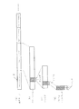
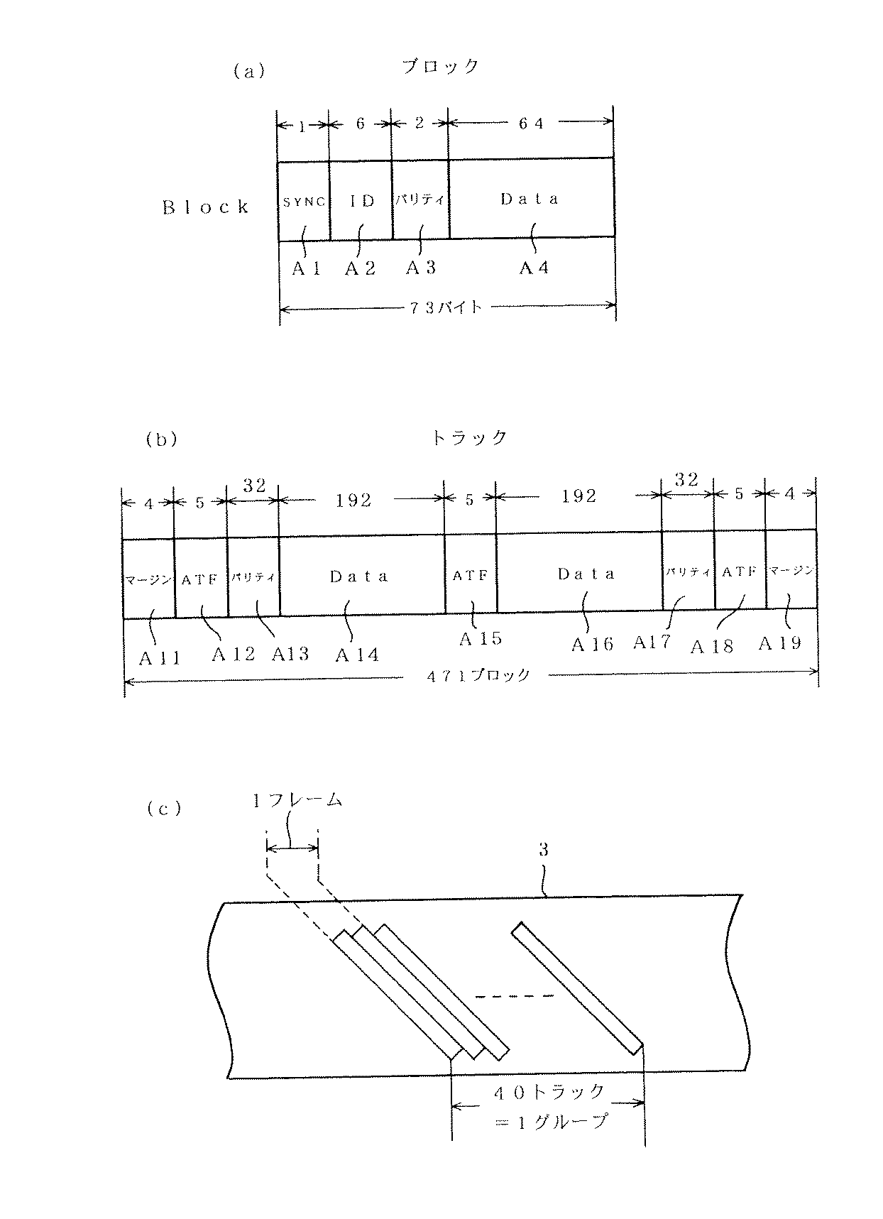
また、図6(d)に示した1トラック分のデータの構造は、図7(a)及び図7(b)に示される。図7(a)にはブロック(Block)単位のデータ構造が示されている。1ブロックは1バイトのSYNCデータエリアA1に続いてサーチ等に用いる6バイトのIDエリアA2、IDデータのための2バイトからなるエラー訂正用のパリティーエリアA3、64バイトのデータエリアA4より形成される。
本実施の形態では、後述するようにテープカセット1の用途が例えば「WORM」とされている場合の記録時に、例えばリモートメモリチップ4に記憶されているテープカセット1の識別情報としてのカートリッジシリアルナンバを記録データと共にデータエリアA4に記録するようにしている。これにより、テープカセット1においてリモートメモリチップ4と磁気テープ3を対応させることができるようになる。
The data structure for one track shown in FIG. 6D is shown in FIGS. 7A and 7B. FIG. 7A shows a data structure in units of blocks. One block is formed of a 1-byte SYNC data area A1, a 6-byte ID area A2 used for searching, a parity area A3 for error correction consisting of 2 bytes for ID data, and a 64-byte data area A4. The
In the present embodiment, as will be described later, for example, when the usage of the
図7(b)に示す1トラック分のデータは全471ブロックにより形成され、1トラックは図のように、両端に4ブロック分のマージンエリアA11、A19が設けられ、これらマージンエリアA11の後ろとマージンA19の前にはトラッキング制御用のATFエリアA12、A18が設けられる。さらに、AFTエリアA12の後ろとATFエリアA18の前にはパリティーエリアA13、A17が備えられる。これらのパリティーエリアA13、A17としては32ブロック分の領域が設けられる。 The data for one track shown in FIG. 7B is formed by all 471 blocks, and one track is provided with margin areas A11 and A19 for four blocks at both ends as shown in the figure. ATF areas A12 and A18 for tracking control are provided in front of the margin A19. Further, parity areas A13 and A17 are provided behind the AFT area A12 and before the ATF area A18. As these parity areas A13 and A17, an area of 32 blocks is provided.
また、1トラックの中間に対してATFエリアA15が設けられ、これらATFエリアA13、A15、A18としては5ブロック分の領域が設けられる。そして、パリティーエリアA13とATFエリアA15の間と、ATFエリアA15とパリティーエリアA17との間にそれぞれ192ブロック分のデータエリアA14、A16が設けられる。したがって、1トラック内における全データエリア(A14及びA16)は、全471ブロックのうち、192×2=384ブロックを占めることになる。
そして上記トラックは、磁気テープ3上に対して図7(c)に示すようにして物理的に記録され、前述のように40トラック(=20フレーム)で1グループとされることになる。
In addition, an ATF area A15 is provided in the middle of one track, and areas for five blocks are provided as these ATF areas A13, A15, and A18. Data areas A14 and A16 for 192 blocks are provided between the parity area A13 and the ATF area A15 and between the ATF area A15 and the parity area A17, respectively. Therefore, all data areas (A14 and A16) in one track occupy 192 × 2 = 384 blocks out of all 471 blocks.
The tracks are physically recorded on the
図6、図7で説明した磁気テープ3には、図8に示すエリア構造によりデータ記録が行われることになる。
なお、ここではパーティションが#0〜#N−1までとしてN個形成されている例をあげている。
Data recording is performed on the
In this example, N partitions are formed as # 0 to # N-1.
図8(a)に示すように、磁気テープの最初の部分には物理的にリーダーテープが先頭に位置しており、次にテープカセットのローディング/アンローディングを行う領域となるデバイスエリアが設けられている。このデバイスエリアの先頭が物理的テープの先頭位置PBOT(Phisycal Begining of Tape)とされる。
上記デバイスエリアに続いては、パーティション#0に関してのリファレンスエリア及びテープの使用履歴情報等が格納されるシステムエリア(以下、リファレンスエリアを含めてシステムエリアという)が設けられて、以降にデータエリアが設けられる。システムエリアの先頭が論理的テープの開始位置LBOT(Logical Begining of Tape) とされる。
As shown in FIG. 8 (a), the first portion of the magnetic tape is physically provided with the leader tape at the head, and a device area serving as an area for loading / unloading the tape cassette is provided next. ing. The head of the device area is a physical tape head position PBOT (Phisycal Begining of Tape).
Subsequent to the device area, there is a system area (hereinafter referred to as a system area including the reference area) for storing a reference area and a tape usage history information regarding the
このシステムエリアには、図8(c)に拡大して示すように、リファレンスエリア、ポジショントレランスバンドNO.1、システムプリアンブル、システムログ、システムポストアンブル、ポジショントレランスバンドNO.2、ベンダーグループプリアンブルが形成される。 As shown in an enlarged view in FIG. 8C, the system area includes a reference area, a position tolerance band NO. 1, system preamble, system log, system postamble, position tolerance band NO. 2. A vendor group preamble is formed.
このようなシステムエリアに続くデータエリアにおいては、図8(b)に拡大して示すように、最初にデータを作成して供給するベンダーに関する情報が示されるベンダーグループが設けられ、続いて図6(c)に示したグループが、ここではグループ1〜グループ(n)として示すように複数連続して形成されていくことになる。そして最後のグループ(n)の後にアンブルフレームが配される。
In the data area following such a system area, as shown in an enlarged view in FIG. 8B, a vendor group in which information relating to vendors that create and supply data is first provided is provided. A plurality of groups shown in (c) are formed continuously as shown here as
このようなデータエリアに続いて図8(a)のように、パーティションのデータ領域の終了を示すEOD(End of Data)の領域が設けられる。
パーティションが1つしか形成されない場合は、そのパーティション#0のEODの最後が、論理的テープの終了位置LEOT(Logical End of Tape)とされるが、この場合はN個のパーティションが形成されている例であるため、パーティション#0のEODに続いてオプショナルデバイスエリアが形成される。
上記した先頭位置PBOTからのデバイスエリアは、パーティション#0に対応するロード/アンロードを行うエリアとなるが、パーティション#0の最後のオプショナルデバイスエリアは、パーティション#1に対応するロード/アンロードを行うエリアとなる。また、本例では後述するように排出位置情報に基づいて、排出管理領域としてのデバイスエリアまたはオプショナルデバイスエリアを任意に選択することができるようにされている。つまり、所望する位置でのアンロードを可能なものとしている。
Subsequent to such a data area, as shown in FIG. 8A, an EOD (End of Data) area indicating the end of the data area of the partition is provided.
When only one partition is formed, the end of the EOD of the
The device area from the head position PBOT is an area for loading / unloading corresponding to partition # 0, but the last optional device area of
パーティション#1としては、パーティション#0と同様にエリアが構成され、またその最後には次のパーティション#2に対応するロード/アンロードを行うエリアとなるオプショナルデバイスエリアが形成される。
以降、パーティション#(N−1)までが同様に形成される。
なお、最後のパーティション#(N−1)では、オプショナルデバイスエリアは不要であるため形成されず、パーティション#(N−1)のEODの最後が、論理的テープの終了位置LEOT(Logical End of Tape)とされる。
PEOT(Phisycal End of Tape) は、物理的テープの終了位置、またはパーティションの物理的終了位置を示すことになる。
As
Thereafter, up to partition # (N−1) is formed in the same manner.
In the last partition # (N-1), an optional device area is unnecessary and thus is not formed. The end of the EOD of the partition # (N-1) is the logical tape end position LEOT (Logical End of Tape). ).
PEOT (Phisycal End of Tape) indicates the end position of the physical tape or the physical end position of the partition.
5.IDエリア
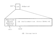
次に、図7(a)に示したIDエリアA2について図9〜図11を参照して説明する。
図9はIDエリアA2のデータ構造を示すものとされ、このIDエリアA2は9ビットのフィジカルブロックアドレス(Physical Block Address)A21と、これに続く39ビットのIDインフォメーションエリア(ID Information Area) A22の領域よりなる。
5). ID Area Next, the ID area A2 shown in FIG. 7A will be described with reference to FIGS.
FIG. 9 shows the data structure of the ID area A2. This ID area A2 is composed of a 9-bit physical block address (A21) followed by a 39-bit ID information area (ID Information Area) A22. It consists of areas.
前述のように、1トラック内における全データエリア(A14及びA16)は384ブロックよりなることから、これら全データエリアに含まれるフィジカルブロックアドレスA21の数も384とされることになる。
そして、これら384のフィジカルブロックアドレスA21は、例えば図10に模式的に示すように1トラックの先頭に位置するフィジカルブロックアドレスA21から順に、10進法表現で0〜383までインクリメントするようにしてアドレス値が与えられる。
これにより、例えば記録再生装置側により、1トラック内のデータエリアに含まれるIDインフォメーションエリアA22の情報を適正に扱うことが可能なようにされる。ここで、1トラック内のデータエリアに含まれるIDインフォメーションエリアA22のデータサイズとしては、
39(Bit )×384(Block)=14976(Bit)=1872(Byte)
で求められるように、1872バイトとなる。
As described above, since all data areas (A14 and A16) in one track are composed of 384 blocks, the number of physical block addresses A21 included in all the data areas is also 384.
These 384 physical block addresses A21 are, for example, addresses incremented from 0 to 383 in decimal notation sequentially from the physical block address A21 located at the head of one track as schematically shown in FIG. A value is given.
Thereby, for example, the information in the ID information area A22 included in the data area in one track can be appropriately handled by the recording / reproducing apparatus side. Here, as the data size of the ID information area A22 included in the data area in one track,
39 (Bit) x 384 (Block) = 14976 (Bit) = 1872 (Byte)
As required by the above, it becomes 1872 bytes.
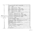
図11は、図9に示したIDインフォメーションエリアA22に格納されるIDエリア情報の種類を示すものとされ、この図に示す各IDエリア情報が1トラック上のデータエリアに含まれる、計1872バイトのIDインフォメーションエリアA22、A22・・・・の領域に対して、所定の規則に従って当て嵌められるようにして格納されることになる。また、テープストリーマドライブ10によるIDエリア情報の確実な読み出しを可能とさせることを考慮して、1トラックごとに同一の種類のIDエリア情報が所定の規則に従って複数回記録される。
FIG. 11 shows the types of ID area information stored in the ID information area A22 shown in FIG. 9, and each ID area information shown in this figure is included in the data area on one track, totaling 1872 bytes. The ID information areas A22, A22,... Are stored according to a predetermined rule. Further, in consideration of enabling reliable reading of the ID area information by the
この図11において、ロウフォーマットID(Raw Format ID:16bit) は、磁気テープに関する基本的フォーマットのタイプが示され、本例の場合には、例えばトラックピッチ、1フレームのデータサイズ、1トラックに含まれるブロック数、1ブロックのデータサイズ、テープ長、テープ厚、テープの材質等の情報が示される。ロジカルフォーマットID(Logical Format ID:8bit) は、実際に使用される記録フォーマットのタイプが示される。
ロジカルフレームID(Logical Frame ID:8bit)は、図のようにラストフレームID(Last Frame ID:1bit) 、ECCフレームID(ECC Frame ID:1bit) 、及びロジカルフレームナンバ(Logical Frame Number:6bit)よりなる。ラストフレームIDは、当該IDエリアが含まれる現フレームが、グループ内の最後のフレームであるか否かを示し、ECCフレームIDは、現フレームのデータエリアの記録データがECC(誤り訂正符号)とされているか否かを示す。
In FIG. 11, a raw format ID (Raw Format ID: 16 bit) indicates a basic format type relating to a magnetic tape. In this example, for example, a track pitch, a data size of one frame, and one track are included. Information such as the number of blocks to be processed, data size of one block, tape length, tape thickness, tape material, and the like is shown. The logical format ID (Logical Format ID: 8bit) indicates the type of recording format that is actually used.
Logical frame ID (Logical Frame ID: 8bit) is based on the last frame ID (Last Frame ID: 1bit), ECC frame ID (ECC Frame ID: 1bit), and logical frame number (Logical Frame Number: 6bit) as shown in the figure. Become. The last frame ID indicates whether or not the current frame including the ID area is the last frame in the group. The ECC frame ID indicates that the recording data in the data area of the current frame is ECC (error correction code). Indicates whether or not
また、前述のように1グループは20フレームよりなるが、ロジカルフレームナンバは、当該フレームが現グループ内の何番目のフレームであるかを示す。 Further, as described above, one group includes 20 frames, and the logical frame number indicates the number of the frame in the current group.
パーティションID(Partition ID:16bit)は、現フレームを含むパーティションのパーティションナンバが示される。 The partition ID (Partition ID: 16 bits) indicates the partition number of the partition including the current frame.
エリアID(Area ID:4bit) は、当該フレームがどのエリアに属しているかを示すものとされる。データID(Data ID:4bit) は、記録フォーマットに基づくデータの処理形態のタイプが示され、N−ポジション(N-Position:4bit )及びN−リピート(N-Repeats:4bit) は多重記録モードに対応するデータに関する情報が定義される。
グループカウント(Group Count:24bit)は、現パーティションにおいて当該フレームが含まれるグループまでのグループの総数を示す。また、ファイルマークカウント(File-Mark Count:32bit)は、現パーティションにおいて、その開始位置から現グループまでに含まれるファイルマークの総数が示される。ファイルマークは1パーティション内におけるデータファイルの区切りを示す情報とされる。
The area ID (Area ID: 4bit) indicates which area the frame belongs to. Data ID (Data ID: 4bit) indicates the type of data processing based on the recording format, and N-position (N-Position: 4bit) and N-Repeat (N-Repeats: 4bit) are in the multiple recording mode. Information about the corresponding data is defined.
The group count (Group Count: 24 bits) indicates the total number of groups up to the group including the frame in the current partition. The file mark count (File-Mark Count: 32 bits) indicates the total number of file marks included in the current partition from the start position to the current group. The file mark is information indicating a delimiter of the data file in one partition.
セーブセットマークカウント(Sava-Set Mark Count:32bit) は、現パーティションにおいて、その開始位置から現グループまでに含まれるファイルマークの総数が示される。セーブセットマークカウントは1パーティション内における、データセーブ位置の区切りを示す情報とされる。
レコードカウント(Record Count:32bit)は、現パーティションにおいて、その開始位置から現グループまでに含まれるレコードの総数が示される。アブソリュートフレームカウント(Absolute Frame Count:24bit)は、現パーティションにおいて、その開始位置から現グループまでに含まれるフレームの総数が示される。また、将来のIDエリア情報の追加等に備えて未定義(Reserved)の領域が設けられる。
なお、この図に示すIDエリア情報の定義及び各IDエリア情報に与えられるビット数等は一例であり、実際の使用条件に応じて変更されて構わない。
The save set mark count (Sava-Set Mark Count: 32 bits) indicates the total number of file marks included in the current partition from the start position to the current group. The save set mark count is information indicating a delimiter between data save positions in one partition.
The record count (Record Count: 32 bits) indicates the total number of records included in the current partition from the start position to the current group. The absolute frame count (Absolute Frame Count: 24 bits) indicates the total number of frames included in the current partition from the start position to the current group. In addition, an undefined (Reserved) area is provided in preparation for future addition of ID area information.
It should be noted that the definition of ID area information and the number of bits given to each ID area information shown in this figure are examples, and may be changed according to actual use conditions.
6.リモートメモリチップのデータ構造
次に、テープカセット1に備えられるMIC(リモートメモリチップ4、接触型メモリ104)のデータ構造について説明する。
図12は、MICに記憶されるデータの構造の一例を摸式的に示す図である。このMICの記憶領域としては図示されているようにフィールドFL1〜FL4が設定されている。
これらフィールドFL1〜FL4において、テープカセットの製造時の各種情報、初期化時のテープ情報やパーティションごとの情報などが書き込まれる。
6). Next, the data structure of the MIC (
FIG. 12 is a diagram schematically illustrating an example of the structure of data stored in the MIC. As shown in the figure, fields FL1 to FL4 are set as storage areas of the MIC.
In these fields FL1 to FL4, various information at the time of manufacturing the tape cassette, tape information at the time of initialization, information for each partition, and the like are written.
フィールドFL1はマニファクチャーインフォーメーション(Manufacture Information)とされ、主にテープカセットの製造時の各種情報が記憶されるマニュファクチャーパートとされている。
フィールドFL2はメモリマネージメントインフォーメーション(Memory Management Information)とされ、主に初期化時の情報等が記憶されるドライブイニシャライズパートとされている。
フィールドFL3はボリュームタグ(Volume Tag)とされ、テープカセット全体の基本的な管理情報が記憶される。
The field FL1 is a manufacture information (Manufacture Information), and is a manufacture part that mainly stores various information at the time of manufacturing the tape cassette.
The field FL2 is a memory management information (Memory Management Information), which is a drive initialization part that mainly stores information at the time of initialization.
The field FL3 is a volume tag and stores basic management information of the entire tape cassette.
フィールドFL4は、メモリーフリープールの領域とされ、管理情報の追加記憶が可能な領域とされる。このメモリーフリープールには記録再生動作の経過や必要に応じて各種情報が記憶される。なお、メモリーフリープールに記憶される1単位のデータ群を「セル」ということとする。
まず、磁気テープ3に形成されるパーティションに応じて、各パーティションに対応する管理情報となるパーティションインフォメーションセル#0、#1・・・がメモリーフリープールの先頭側から順次書き込まれる。つまり磁気テープ3上に形成されたパーティションと同数のセルとしてパーティションインフォメーションセルが形成される。
The field FL4 is an area of a memory free pool, and an area where management information can be additionally stored. In the memory free pool, various information is stored as the recording / reproducing operation progresses and as necessary. A unit of data stored in the memory free pool is referred to as a “cell”.
First, in accordance with the partitions formed on the
またメモリーフリープールの後端側からは、高速サーチ用のマップ情報としてのスーパーハイスピードサーチマップセル(Super High Speed Search Map Cell)が書き込まれる。
また続いて後端側からユーザボリュームノートセルや、ユーザパーティションノートセルが書き込まれる。ユーザボリュームノートセルはテープカセット全体に関してユーザが入力したコメント等の情報であり、ユーザパーティションノートセルは各パーティションに関してユーザが入力したコメント等の情報である。したがって、これらはユーザが書込を指示した際に記憶されるものであり、これらの情報が必ずしも全て記述されるものではない。
またこれらの情報が記憶されていない中間の領域は、メモリーフリープールとして後の書込のために残される。
Also, from the rear end side of the memory free pool, a super high speed search map cell (Super High Speed Search Map Cell) is written as map information for high speed search.
Subsequently, a user volume note cell and a user partition note cell are written from the rear end side. The user volume note cell is information such as a comment input by the user regarding the entire tape cassette, and the user partition note cell is information such as a comment input by the user regarding each partition. Therefore, these are stored when the user instructs writing, and all of these pieces of information are not necessarily described.
An intermediate area in which these pieces of information are not stored is left as a memory free pool for later writing.
フィールドFL1のマニファクチャーインフォーメーションは、例えば図13に示すような構造とされる。
マニュファクチャーインフォーメーションには、まず先頭マニュファクチャパートチェックサム(manufacture part checksum)として、このマニュファクチャーインフォーメーションのデータに対するチェックサムの情報が格納される。このマニュファクチャパートチェックサムの情報はカセット製造時に与えられる。
The manufacture information of the field FL1 has a structure as shown in FIG. 13, for example.
In the manufacture information, checksum information for the data of the manufacture information is stored as a first manufacture part checksum. Information on the manufacture part checksum is given when the cassette is manufactured.
そしてマニュファクチャーパートを構成する実データとしてMICタイプ(mic type)からライトプロテクトバイトカウント(Write Protect byte count)までが記述される。なおリザーブ(reserved)とは、将来的なデータ記憶のための予備とされている領域を示している。これは以降の説明でも同様である。 Then, from the MIC type (mic type) to the write protect byte count (Write Protect byte count) is described as the actual data constituting the manufacture part. Note that “reserved” indicates an area reserved for future data storage. This is the same in the following description.
MICタイプ(mic type)は、当該テープカセットに実際に備えられるMICのタイプを示すデータである。
MICマニュファクチャデート(mic manufacture date)は、当該MICの製造年月日(及び時間)が示される。
MICマニュファクチャラインネーム(mic manufacture line name)はMICを製造したライン名の情報が示される。
MICマニュファクチャプラントネーム(mic manufacture plant name)はMICを製造した工場名の情報が示される。
MICマニュファクチュアラネーム(mic manufacturer name)は、MICの製造社名の情報が示される。
MICネーム(mic name)はMICのベンダー名の情報が示される。
The MIC type is data indicating the type of MIC actually provided in the tape cassette.
The MIC manufacture date indicates the date of manufacture (and time) of the MIC.
The MIC manufacture line name indicates information on the name of the line that manufactured the MIC.
The MIC manufacture plant name indicates information on the name of the factory that manufactured the MIC.
The MIC manufacturer name indicates information on the name of the MIC manufacturer.
The MIC name (mic name) indicates information on the vendor name of the MIC.
またカセットマニュファクチャデート(cassette manufacture date)、カセットマニュファクチャラインネーム(cassette manufacture line name)、カセットマニュファクチャプラントネーム(cassette manufacture plant name)、カセットマニュファクチュアラネーム(cassette manufacturer name)、カセットネーム(cassette name)は、それぞれ上記したMICに関する情報と同様のカセット自体の情報が記述される。 Also, cassette manufacture date, cassette manufacture line name, cassette manufacture plant name, cassette manufacturer name, cassette name (Cassette name) describes information on the cassette itself similar to the information on the MIC described above.
OEMカスタマーネーム(oem customer name)としては、OEM(Original Equipment Manufactures)の相手先の会社名の情報が格納される。
フィジカルテープキャラクタリステックID(physical tape characteristic ID)としては、例えば、テープの材質、テープ厚、テープ長等の、物理的な磁気テープ3の特性の情報が示される。
マキシマムクロックフリケンシー(maximum clock frequency)としては、当該MICが対応する最大クロック周波数を示す情報が格納される。
ブロックサイズ(Block size)では、例えばMICの特性としてテープストリーマドライブ10との1回の通信によって何バイトのデータを転送することができるかという情報が示される。この情報はMICとして使用する不揮発性メモリの物理的な特性に依存するものとされる。
MICキャパシティ(mic capacity)としては、当該MICの記憶容量情報が示される。
As the OEM customer name (Oem customer name), information on the company name of the counterpart of OEM (Original Equipment Manufactures) is stored.
As the physical tape characteristic ID (physical tape characteristic ID), for example, information on characteristics of the physical
As the maximum clock frequency, information indicating the maximum clock frequency supported by the MIC is stored.
In the block size (Block size), for example, information indicating how many bytes of data can be transferred by one communication with the
As the MIC capacity, the storage capacity information of the MIC is indicated.
ライトプロテクトトップアドレス(write protect top address)は、MICの所要の一部の領域を書き込み禁止とするために用いられ、書き込み禁止領域の開始アドレスを示す。
ライトプロテクトカウント(write protect count)は書き込み禁止領域のバイト数が示される。つまり、上記ライトプロテクトトップアドレスで指定されたアドレスから、このライトプロテクトカウントの領域により示されるバイト数により占められる領域が書き込み禁止領域として設定されることになる。
The write protect top address is used for prohibiting writing in a required partial area of the MIC, and indicates the start address of the write prohibited area.
The write protect count indicates the number of bytes in the write protected area. That is, the area occupied by the number of bytes indicated by the area of the write protect count from the address specified by the write protect top address is set as the write prohibit area.
フィールドFL11に示されているウォームフラグ(worm flag)は、テープカセット1の用途識別情報として、例えば「汎用」「WORM」などを示す。なお、ウォームフラグについては後で図21で詳しく説明する。
A worm flag shown in the field FL11 indicates, for example, “general purpose” or “WORM” as the application identification information of the
続いて図12のフィールドFL2のメモリマネジメントインフォーメーションの構造を図14で説明する。
メモリマネジメントインフォーメーションにはまずドライブイニシャライズパートチェックサム(drive Initialize part checksum)として、このドライブイニシャライズパートとされるメモリマネジメントインフォーメーションのデータに対するチェックサムの情報が格納される。
Next, the structure of the memory management information in the field FL2 in FIG. 12 will be described with reference to FIG.
In the memory management information, first, as the drive initialization part checksum, information on the checksum for the data of the memory management information used as the drive initialization part is stored.
そしてメモリマネージメントインフォーメーションを構成する実データとしてMICロジカルフォーマットタイプ(mic logical format type)からフリープールボトムアドレス(Free Pool Bottom Address)までの情報が記述される。 Information from the MIC logical format type to the free pool bottom address is described as actual data constituting the memory management information.
まずMICロジカルフォーマットタイプ(mic logical format type)として、MICの論理フォーマットのIDナンバが格納される。MICフォーマットとしては、例えば、基本MICフォーマットのほかに、ファームウェア更新テープMICフォーマット、リファレンステープMICフォーマット、クリーニングカセットMICフォーマット等に関連するフォーマットが各種存在するものとされ、当該テープカセットのMICフォーマットに応じたIDナンバが示されることになる。 First, as the MIC logical format type, the ID number of the MIC logical format is stored. As the MIC format, for example, there are various formats related to the firmware update tape MIC format, the reference tape MIC format, the cleaning cassette MIC format, etc. in addition to the basic MIC format, and depending on the MIC format of the tape cassette. ID number will be displayed.
アブソリュートボリュームマップポインタ(absolute volume map pointer)には図12のスーパーハイスピードサーチマップセルの領域の先頭アドレスを示すポインタが配置される。
ユーザボリュームノートセルポインタ(user volume note cell pointer)は、テープカセットに対してユーザがSCSI経由で自由にデータの読み書きが可能な記憶領域、つまり図12に示したユーザボリュームノートセルの開始アドレスを示す。
ユーザパーティションノートセルポインタ(user partition note cell pointer)は、各パーティションに対してユーザがSCSI経由で自由にデータの読み書きが可能な記憶領域、つまり図12のユーザパーティションノートセルの開始アドレスを示している。なおユーザパーティションノートセルは複数個記憶される場合があるが、このユーザパーティションノートセルポインタは、複数のユーザパーティションノートセルのうちの先頭のセルの開始アドレスを示すことになる。
In the absolute volume map pointer, a pointer indicating the top address of the super high speed search map cell area of FIG. 12 is arranged.
The user volume note cell pointer indicates a storage area where the user can freely read and write data via SCSI from the tape cassette, that is, the start address of the user volume note cell shown in FIG. .
The user partition note cell pointer indicates a storage area where the user can freely read and write data via SCSI for each partition, that is, the start address of the user partition note cell in FIG. . A plurality of user partition note cells may be stored, but this user partition note cell pointer indicates the start address of the first cell among the plurality of user partition note cells.
パーティションインフォーメーションセルポインタ(partition information cell pointer)は、図12のパーティションインフォメーションセル#0の開始アドレスを示す。
メモリーフリープールに書き込まれていくパーティションインフォーメーションは、磁気テープ3に形成されるパーティションの数だけ形成されることになるが、全てのパーティションインフォーメーションセル#0〜#Nはリンク構造によりポインタによって連結されている。つまり、パーティションインフォーメーションセルポインタがパーティション#0のアドレスを示すルートとされ、それ以降のパーティションインフォメーションセルのポインタは、直前のパーティションインフォメーションセル内に配される。
The partition information cell pointer indicates the start address of the partition
The partition information written to the memory free pool is formed by the number of partitions formed on the
以上のように各ポインタ(アブソリュートボリュームマップポインタ、ユーザボリュームノートセルポインタ、ユーザパーティションノートセルポインタ、パーティションインフォーメーションセルポインタ)により、フィールドFL4内の各データ位置が管理される。 As described above, each data position in the field FL4 is managed by each pointer (absolute volume map pointer, user volume note cell pointer, user partition note cell pointer, partition information cell pointer).
ボリュームアトリビュートフラグ(Volume Attribute Flags)は、MICに対する論理的な書込み禁止タブを提供するためのフラグとされている。すなわち、MICヘッダフラグが示す内容としては、マニュファクチャーパート部分の書込み許可/禁止、またはマニュファクチャーパート以外の部分の書込み許可/禁止とされる。 The volume attribute flag is a flag for providing a logical write-protect tab for the MIC. In other words, the contents indicated by the MIC header flag are permission / prohibition of writing in the manufacture part, or permission / inhibition of writing in parts other than the manufacture part.
フリープールトップアドレス(Free Pool Top Address)及びフリープールボトムアドレス(Free Pool Bottom Address)は、フィールドFL2におけるその時点でのメモリーフリープールの開始アドレスと終了アドレスを示す。メモリーフリープールとしての領域は、パーティションインフォメーションやユーザーパーティションノート等の書込や消去に応じて変化するため、それに応じてフリープールトップアドレスやフリープールボトムアドレスが更新される。 The free pool top address and the free pool bottom address indicate the start address and the end address of the memory free pool at that time in the field FL2. Since the area as the memory free pool changes according to the writing or erasing of partition information, user partition notes, etc., the free pool top address and the free pool bottom address are updated accordingly.
続いて図12のフィールドFL3のボリュームタグの構造を図15で説明する。
ボリュームタグの先頭にはボリュームインフォメーションチェックサム(Volume Information Checksum)として、テープカセット全体の基本的な管理情報が記憶されるボリュームインフォメーション(Volume Information)のデータに対するチェックサムの情報が格納される。
さらに、アキュムレイティブパーティションインフォーメーションチェックサム(Accumulative Partition Information Checksum)として、テープカセット製造時からの履歴情報が記憶されるアキュムレイティブパーティションインフォメーション(Accumulative Partition Information)のデータに対するチェックサムの情報が格納される。
Next, the structure of the volume tag in the field FL3 in FIG. 12 will be described with reference to FIG.
At the head of the volume tag, checksum information for volume information (Volume Information) data in which basic management information of the entire tape cassette is stored is stored as a Volume Information Checksum.
In addition, as the Accumulating Partition Information Checksum (Accumulative Partition Information Checksum), the information of the checksum for the data of Accumulating Partition Information (Accumulative Partition Information) that stores the history information from the time of tape cassette manufacture is stored. The
ボリュームノートチェックサム(Volume note checksum)、ボリュームノート(Volume note)に続いて、カートリッジシリアルナンバ(Cartridge Serial Number)は、例えばASCIIコードに基づいた32文字の文字情報とされるシリアルナンバが格納される。
マニュファクチャーID(Manufacturer ID)は、製造業者識別子としてテープカセット1の製造業者のコードナンバーが格納される。
セカンダリーID(Secondary ID)は、テープカセット1のタイプに応じた二次識別子とされ、例えばコード値としてテープの属性情報が格納される。
カートリッジシリアルナンバーパートチェックサム(Cartridge Serial Number Part Checksum)は、カートリッジシリアルナンバ、マニュファクチャーID、セカンダリーIDのチェックサム情報とされる。
スペシフィックボリュームタグ(Specific Volume Tag)1乃至13は例えばリザーブとして、各エリアが構成されている。
Subsequent to the volume note checksum and the volume note, the cartridge serial number stores, for example, a serial number as 32-character information based on the ASCII code. .
The manufacturer ID (Manufacturer ID) stores the code number of the manufacturer of the
The secondary ID is a secondary identifier corresponding to the type of the
The cartridge serial number part checksum is the checksum information of the cartridge serial number, the manufacture ID, and the secondary ID.
Specific volume tags (Specific Volume Tags) 1 to 13 each have a reserved area, for example.
図16はボリュームタグFL3のボリュームインフォメーションFL31の構造を説明する図である。
図16(a)に示すようにボリュームインフォメーションには、先頭1バイトにボリュームインフォメーションチェックサム(Volume Information checksum)として、このボリュームインフォメーションのデータに対するチェックサムの情報が格納される。
そしてボリュームインフォメーションを構成する実データとして20バイトのイジェクトステイタス(Eject Status)、4バイトのリール巻径(Reel Diameter)、3バイトのイニシャライズカウント(Initialize Count)、72バイトのボリュームインフォメーションオンテープ(Volume Information On Tape)が記述される。
FIG. 16 is a diagram for explaining the structure of the volume information FL31 of the volume tag FL3.
As shown in FIG. 16A, the volume information stores the checksum information for the volume information data as the volume information checksum in the first byte.
As actual data constituting the volume information, 20 bytes of Eject Status, 4 bytes of reel diameter (Reel Diameter), 3 bytes of initialization count (Initialize Count), 72 bytes of volume information on tape (Volume Information) On Tape) is described.
そして、ボリュームインフォメーションオンテープFL311の内容は図16(b)に示されているようになる。
図示されているように、ボリュームインフォメーションオンテープFL311はリザーブとしての領域を除いて、1ビットのスーパーハイスピードサーチイネーブルフラグ(Super High Speed Search Enable Flag)、2ビットのシステムログアロケーションフラグ(System Log Allocation Flags)、オールウエイズアンロードPBOTフラグ(Always Unload PBOT Flags)、1ビットのAITネイティブフラグ(AIT Native Flag)、1バイトのラストバリッドパティションナンバ(Last Valid Partition Number)、32バイトのオプショナルデバイスエリアアロケーションマップ(Optional Device Area Allocation Map)が記述される。
The contents of the volume information on tape FL311 are as shown in FIG.
As shown in the figure, the volume information on tape FL311 is a 1-bit Super High Speed Search Enable Flag, a 2-bit System Log Allocation Flag (System Log Allocation Flag) except for the reserved area. Flags), Always Unload PBOT Flags, 1-bit AIT Native Flag, 1-byte Last Valid Partition Number, 32-byte optional device area allocation A map (Optional Device Area Allocation Map) is described.
スーパーハイスピードサーチイネーブルフラグは、後述するMICのスーパーハイスピードサーチマップとして格納したテープ位置情報を利用して、ノーマルサーチに対する高速サーチ機能を有効にするか否かを指示するフラグとされる。このフラグが、例えば「1」とされている場合に高速サーチが有効になる。
システムログアロケーションフラグは、テープカセットの使用履歴(システムログ)が何処に格納されているかを示すフラグとされ、例えば磁気テープ3上のみに記録されている、または磁気テープ3及びMICの双方に記録されていない、または磁気テープ3及びMICの双方に記録されている、またはMIC4のみに記録されているかを識別することができるようにされている。
The super high speed search enable flag is a flag for instructing whether or not to enable the high speed search function for the normal search by using the tape position information stored as the MIC super high speed search map described later. For example, when this flag is “1”, the high-speed search is effective.
The system log allocation flag is a flag indicating where the tape cassette usage history (system log) is stored. For example, the system log allocation flag is recorded only on the
オールウェイズアンロードPBOTフラグは磁気テープ3にマルチパーティションが形成され、しかもパーティションにオプショナルデバイスエリアが在ったとしても、PBOTに在るデバイスエリアでアンロードを行なうことを指示するフラグとされる。
AITネイティブフラグはテープカセット1のモードを示すフラグとされる。
ラストバリッドパーティションナンバは、形成されている最後のパーティションのナンバを示す。
The always unload PBOT flag is a flag for instructing unloading in the device area in the PBOT even if a multi-partition is formed on the
The AIT native flag is a flag indicating the mode of the
The last valid partition number indicates the number of the last partition formed.
オプショナルデバイスエリアマップは、256ビットからなり磁気テープ3上に形成される各パーティションそれぞれに各1ビットが対応している。そして、ビットの値が「1」とされている場合は当該ビットに対応したパーティションにオプショナルデバイスエリアが形成されていることを示している。
The optional device area map is composed of 256 bits, and one bit corresponds to each partition formed on the
続いて図12に示すフィールドFL4に記憶されるセルについて説明する。
上記したようにフィールドFL4にはパーティションインフォメーションセル、ユーザパーティションノートセル、スーパーハイスピードサーチマップセル等が記憶される。
これらの各セルの構造を図17に示す。
1つのセルは図17(a)に示すように8バイトのリンクインフォメーションと、nバイト(セル種別によって異なる)のデータから形成される。
Next, the cell stored in the field FL4 shown in FIG. 12 will be described.
As described above, the partition information cell, the user partition note cell, the super high speed search map cell, and the like are stored in the field FL4.
The structure of each of these cells is shown in FIG.
One cell is formed from 8-byte link information and n-byte data (which differs depending on the cell type) as shown in FIG.
8バイトのリンクインフォメーションは、各セルに設けられているもので、その構造は図17(b)のようになる。
まずセル内のデータに関するチェックサムとして、1バイトのセルチェックサム(cell checksum)が設けられる。
また2バイトのセルサイズ(cell size)として、そのセルのサイズが示される。
The 8-byte link information is provided in each cell, and its structure is as shown in FIG.
First, a 1-byte cell checksum is provided as a checksum for data in a cell.
In addition, the cell size is indicated as a 2-byte cell size.
プリビアスセルポインタ(previous cell pointer)及びネクストセルポインタ(next cell pointer)は、実際のリンケージデータ(リンク構造を構築するデータ)であり、同一種類の複数のセルがリンクされる際に、このプリビアスセルポインタとネクストセルポインタで前後のセルが指定される。 The previous cell pointer and the next cell pointer are actual linkage data (data for constructing a link structure), and when multiple cells of the same type are linked, The previous and next cells are specified by the bias cell pointer and the next cell pointer.
このような構造のセルとしては、パーティションインフォメーションセル、スーパーハイスピードサーチマップセル、ユーザボリュームノートセル、ユーザパーティションノートセルが存在する。そしてパーティションインフォメーションセルは、セルサイズは固定値となる。その他のセルは、セルサイズは可変値となる。 As cells having such a structure, there are a partition information cell, a super high speed search map cell, a user volume note cell, and a user partition note cell. The partition information cell has a fixed cell size. Other cells have variable cell sizes.
セルサイズが固定値となるパーティションインフォメーションセルについて図18、図19で説明する。
パーティションインフォメーションセルは、図18に示すように8バイトのリンクインフォメーションと、56バイトのデータから形成される。そして56バイトのデータのうち8バイトはパーティションメモとされ、48バイトはパーティションインフォメーションとされる。
A partition information cell having a fixed cell size will be described with reference to FIGS.
The partition information cell is formed of 8-byte link information and 56-byte data as shown in FIG. Of the 56 bytes of data, 8 bytes are used as partition memos, and 48 bytes are used as partition information.
このパーティションインフォメーション(システムログ)には、そのセルが対応するパーティションにおける磁気テープ3に対する使用履歴に関する各種情報が格納され、テープストリーマドライブが自身の記録/再生動作の管理のための情報として利用されるものとなる。
In this partition information (system log), various types of information regarding the usage history of the
或るパーティションに対応する、1つのパーティションインフォメーションセル内のパーティションインフォメーションのデータ構造は、例えば図19に示すように定義される。
4バイトのプリビアスグループリトゥン(Previous Groups written)には、当該パーティションインフォメーションが最後に更新されたときから起算して、磁気テープ3に対して物理的に記録された当該パーティション内のグループ数の情報が示される。
4バイトのトータルグループリトゥン(Total Groups written)には、これまで当該パーティションに対して記録されたグループの総数が示される。この値は、例えばテープカセットが寿命となって使用不能あるいは廃棄処分されるまで積算される。
これらプリビアスグループリトゥン及びトータルグループリトゥンには、例えば、テープストリーマドライブにより磁気テープ3に対してデータを記録中の状態であれば、テープストリーマドライブのシステムコントローラ15の処理により、現在の記録動作によって新たに記録されるグループ数に応じて、その領域の値がインクリメントされていくことになる。
The data structure of partition information in one partition information cell corresponding to a certain partition is defined as shown in FIG. 19, for example.
In the 4-byte previous group written, information on the number of groups in the partition physically recorded on the
A 4-byte total group written indicates the total number of groups recorded so far for the partition. This value is accumulated until, for example, the tape cassette reaches the end of its life and is unusable or discarded.
In the previous group return and the total group return, for example, when data is being recorded on the
3バイトのプリビアスグループリード(Previous Groups read)には、当該パーティションインフォメーションが最後に更新されたときから起算して、物理的に読み出しが行われたグループ数が示される。
4バイトのトータルグループリード(Total Groups read)には、これまで当該パーティションより読み出されたグループ数が積算された値を示す。
The 3-byte previous group read indicates the number of groups that have been physically read from the last update of the partition information.
A 4-byte total group read indicates a value obtained by integrating the number of groups read from the partition so far.
3バイトのトータルリリトゥンフレーム(Total Rewritten frames)は、当該パーティションにおいてRAWに基づいてデータ再書き込みの要求がなされたフレーム数を積算した値を示すものとされる。 A 3-byte total rewritten frame indicates a value obtained by integrating the number of frames for which data rewrite is requested based on RAW in the partition.
3バイトのトータル3rdECCカウント(Total 3rd ECC count)では、当該パーティションにおいてC3パリティを用いてエラー訂正を行ったグループ数が積算された値が示される。
本例のテープストリーマドライブシステムでは、磁気テープ3より読み出したデータについて、C1,C2,C3のパリティによりエラー訂正を行うようにしているが、C3パリティは、C1,C2パリティのみではデータの回復が図れなかった場合に用いられるものである。
The 3-byte total 3rd ECC count (Total 3rd ECC count) indicates a value obtained by integrating the number of groups in which error correction is performed using C3 parity in the partition.
In the tape streamer drive system of this example, error correction is performed on the data read from the
4バイトのアクセスカウント(Access count)では、テープストリーマドライブが磁気テープ3上の当該パーティションにアクセスした回数が示される。ここでのアクセスとは物理的に当該パーティションを通過した回数をいい、つまりそのパーティションに対する記録または再生が行われた回数、及び通過した回数も含まれる。
The 4-byte access count indicates the number of times the tape streamer drive has accessed the partition on the
4バイトのアップデートリプレイスカウント(Update Replace count)には、アップデートにより当該パーティションにおいて磁気テープ3に対してデータを書き換えた回数を積算した情報が示される。つまり当該パーティションに対する更新回数である。
The 4-byte update replace count indicates information obtained by integrating the number of times data is rewritten on the
2バイトのプリビアスリリトゥンフレーム(Previous rewritten frames)には、先に説明したRAWにより、当該パーティションインフォメーションが最後に更新されたときから起算して、データ再書き込みの要求がなされたパーティション内のフレーム数の情報が示される。 In the 2-byte previous rewritten frames, the number of frames in the partition for which data rewrite has been requested, starting from when the partition information was last updated by the RAW described above. Information is displayed.
2バイトのプリビアス3rdECCカウント(Previous 3rd ECC count)には、当該パーティションインフォメーションが最後に更新されたときから起算して、C3パリティを用いてエラー訂正を行ったグループ数が示される。 The 2-byte previous 3rd ECC count (Previous 3rd ECC count) indicates the number of groups in which error correction has been performed using C3 parity, starting from when the partition information was last updated.
3バイトのロードカウント(Load count)では、テープをロードした回数を積算した値が示される。 The 3-byte load count indicates a value obtained by integrating the number of times the tape has been loaded.
3バイトのバリッドマキシマムアブソリュートフレームナンバ(Valid Maximum Absolute frame Number)は、当該パーティションで有効とされる最後のフレームまでのフレームカウントの情報が示される。
これに対してパーティションインフォメーションの最後の3バイトのマキシマムアブソリュートフレームカウント(Maximum Absolute frame Number)は、当該パーティションの最後のフレームカウントの情報が示される。
The 3-byte valid maximum absolute frame number (Valid Maximum Absolute frame Number) indicates information on the frame count up to the last frame valid in the partition.
On the other hand, the maximum absolute frame number (Maximum Absolute Frame Number) of the last 3 bytes of the partition information indicates information of the last frame count of the partition.
1バイトのパーティションアトリビュートフラグ(Partition Attribute Flag)では、各ビットについてフラグ内容が次のように定義される。
すなわち、プレベントライトフラグ(Prevent Write Flag)、プレベントリードフラグ(Prevent Read Flag)、プレベントライトリトライフラグ(Prevent Write Retry Flag)、プレベントリードリトライフラグ(Prevent Read Retry Flag)として、当該パーティションに対する書き込み許可/禁止、読み出し許可/禁止、及び記録時のRAWに基づくデータの再書き込み許可/禁止、再生時のデータ読出のリトライの許可/禁止、のそれぞれを示すフラグが用意される。
またパーティションオープンクローズフラグ(Partition Open Close Flag)として、当該パーティションに対する記録中にセットされ、記録終了に応じてリセットされるフラグが用意される。
In 1 byte partition attribute flags (Par ti tion Attribute Flag), for each bit flags contents are defined as follows.
That is, write permission / prohibition to the partition as a prevent write flag (Prevent Write Flag), a prevent read flag (Prevent Read Flag), a prevent write retry flag (Prevent Write Retry Flag), and a prevent read retry flag (Prevent Read Retry Flag) Flags indicating read permission / prohibition, data rewrite permission / prohibition based on RAW during recording, and data read retry permission / prohibition during reproduction are prepared.
As a partition open / close flag, a flag that is set during recording on the partition and reset when the recording ends is prepared.
このように、リモートメモリチップ4はフィールドFL1からフィールドFL4に示した記憶領域によって構成されている。
ところで、図12に示したフィールドFL1における各データ項目に付いては、例えばテープカセット1自体の情報やリモートメモリチップ4自体の情報など、ユーザがテープカセットを使用していくうえで更新されない情報とされる。また、テープカセット1の用途を示すウォームフラグ(フィールドFL11)については、その内容が改変されないようにすることが望まれる。そこで、リモートメモリチップ4の記憶領域としては、図20(a)に示されているように 例えばフィールドFL1は読み出し専用とされるROM(Read Only Memory)領域、フィールドFL2〜FL4は読み出し/書き込み可能とされるRWM(Read Write Memory)領域として設定する。これによりフィールドFL1に格納されるデータ項目については、ユーザが改変することができないようにすることができる。
Thus, the
By the way, each data item in the field FL1 shown in FIG. 12 includes information that is not updated when the user uses the tape cassette, such as information on the
また、例えば図20(b)に示されているように、リモートメモリチップ4をフィールドFL1の情報が格納されるROM領域と、フィールドFL2〜FL4の情報が格納されるRWM領域を別体のメモリで構成しても良い。
For example, as shown in FIG. 20B, the
さらに、例えば図20(c)に示されているように、リモートメモリチップ4の全記憶領域をRWM領域として構成し、フィールドFL1を記憶する領域については、書きこみ制御を行う所要の論理回路などからなる書きこみ制御手段を備えることによって、所要のパスワードに基づいた書きこみ処理以外は行うことができないようにすることもできる。
Further, for example, as shown in FIG. 20C, the entire storage area of the
或いは、リモートメモリチップ4の初期状態として、RWM領域のデータを全て「1」(又は「0」)とする。そして、書きこみ制御手段はROM領域として扱う領域内の特定のアドレスにある特定のビットに着目し、このビットを例えばビットαとする。この場合ビットαが「1」(又は「0」)であった場合に、書きこみ制御手段はRWM領域の全領域、即ちリモートメモリチップ4の全領域に対して書きこみ処理を有効なものとする。したがって、ROM領域として扱う領域に対しても書きこみが可能になる。しかしビットαを「0」(又は「1」)にすることで、書きこみ制御手段はROM領域に対する書きこみ処理は無効なものとすることができる。
Alternatively, as an initial state of the
このようにして、フィールドFL1に格納されているデータの内容を改変することができないようにすることで、ウォームフラグを有効な情報とすることができるようになる。したがって、ウォームフラグを書き換えることによって例えば「WORM」として記録されたデータの改変、消去などを行うこともできなくなり、予め設定されている用途のみで使用することが可能となる制約を実現することできる。 In this way, the contents of the data stored in the field FL1 cannot be altered, so that the warm flag can be made valid information. Therefore, by rewriting the warm flag, for example, the data recorded as “WORM” cannot be altered or deleted, and a restriction that can be used only for preset purposes can be realized. .
7.「WORM」に対応した動作制御
図21は本実施の形態における一例として、リモートメモリチップ4のフィールドFL11に格納される用途識別情報としてのウォームフラグについて説明する図である。
この図には、用途番号「0」から「2」、及びその他の例が示されているが、テープストリーマドライブ10ではこの用途番号に基づいて、記録、再生動作に制限を加えることになる。
例えば用途番号が「0」である場合は、そのテープカセット1が汎用とされる記録媒体であることを示し、動作に関する制約はないものとする。つまり、用途番号「0」は、ユーザが使用目的に応じて自由に使用することができるテープカセット1であることを示し、テープストリーマドライブ10ではユーザの操作に基づいてホストコンピュータ40から供給される各種コマンドに応じた動作を実行する。
7). Operation Control Corresponding to “WORM” FIG. 21 is a diagram for explaining a warm flag as use identification information stored in the field FL11 of the
Although the application numbers “0” to “2” and other examples are shown in this figure, the tape streamer drive 10 places restrictions on recording and reproduction operations based on the application numbers.
For example, if the application number is "0" indicates that the
用途番号が「1」である場合は、例えばデータ配布、ファームウエア更新などを目的としたテープカセット1であることを示す。この場合、テープカセット1は再生専用のものとして識別される。したがって、ホストコンピュータ40から例えばフォーマットなどの記録されているデータの更新処理などに関わるコマンドが供給された場合でも、そのコマンドを無効なものとする。
When the usage number is “1”, it indicates that the
また用途番号が「2」である場合は、例えばWORMを目的としたテープカセット1であることを示す。この場合、記録されているデータを保守するために、記録に関しては、例えばパーティション内における最終記録位置を記録開始位置とした記録(追加記録)のみが許可される。すなわち、例えば上書き、消去などといった既に記録されているデータの更新を行う動作は禁止されることになる。したがって、用途番号「2」が設定されているテープカセット1に対しては追加記録または再生動作のみが許可される。この場合も、例えばフォーマットなどの記録されているデータの更新処理などに関わるコマンドは無効なものとされる。
Further, when the usage number is “2”, for example, it indicates that the
さらに、「WORM」において追加記録を行う場合は、図7(a)に示したブロックのデータエリアA4に対して、例えば図15のボリュームタグにおけるカートリッジシリアルナンバを記憶するようにする。したがって、用途が「WORM」として設定されているテープカセット1には、リモートメモリチップ4と磁気テープ3に対して同一の情報が記録されることになる。これにより、テープカセット1においてリモートメモリチップ4と磁気テープ3の対応がとれることになる。したがって、リモートメモリチップ4と磁気テープ3に記憶されているカートリッジシリアルナンバを照合することで、再生動作の実行を制約することが可能になる。つまり、「WORM」とされているテープカセット1のリモートメモリチップ4を交換して、「汎用」とされている他のリモートメモリチップ4を取り付けたような場合、カートリッジシリアルナンバが一致しないことになるので、このような場合は、テープストリーマドライブ10における動作を制約するようにすることができるようになる。
Further, when performing additional recording in “WORM”, for example, the cartridge serial number in the volume tag of FIG. 15 is stored in the data area A4 of the block shown in FIG. Therefore, the same information is recorded on the
さらに、用途番号が上記「0」「1」「2」以外の値はリザーブとされる。したがって、テープストリーマドライブ10では用途番号が「0」「1」「2」以外の値であった場合は、テープストリーマドライブ10としてはテープカセット1の用途を識別することができないとして、この旨をホストコンピュータ40に伝えて、例えば当該テープカセット1を排出するための待機状態に移行する。
なお、用途番号が「1」「2」であった場合に、無効とされるコマンドが供給された場合においても、当該コマンドを実行することができないという旨をホストコンピュータ40に伝えて排出待機状態に移行する。
Further, values other than the usage numbers “0”, “1”, and “2” are reserved. Therefore, if the usage number of the
When the usage number is “1” or “2”, even when an invalid command is supplied, the
また、「WORM」とされている場合、データエリアA4に対してカートリッジシリアルナンバを記憶すると共に、「WORM」とされていることを識別することができる情報(例えば「WORM」という文字情報)を記録するようにしても良い。さらに、「汎用」とされている場合に記録を行う場合において、「汎用」に対応した用途で記録されたデータであることを識別情報(「NORMAL」という文字情報)を記録するようにしても良い。
これにより、テープストリーマドライブ10は磁気テープ3からもテープカセット1の用途識別情報を得ることができるようになる。したがって、リモートメモリチップ4からウォームフラグを得ることができない状態でも、テープカセット1の用途を判別することができるようになる。
When “WORM” is set, information (for example, character information “WORM”) that stores the cartridge serial number in the data area A4 and that can be identified as “WORM” is stored. It may be recorded. Further, when recording is performed when “general” is set, identification information (character information “NORMAL”) indicating that the data is recorded for an application corresponding to “general” may be recorded. good.
As a result, the
ところで、上記した用途番号は、テープカセット1が装填されるテープストリーマドライブ10によって識別されることになるが、テープストリーマドライブ10では用途番号「0」「1」「2」を必ずしも全て認識するように構成しなくても良い。例えば汎用とされているテープカセット1のみを使用することができるように構成されているテープストリーマドライブ10では、あえてWORMを認識する必要がないとみなし、例えば用途番号「1」「2」を検出した場合でも、例えば当該テープカセット1を排出するための待機状態に移行すればよい。
また用途番号「1」を認識することができるテープストリーマドライブ10としては、データの少なくとも再生を行うことができる構成とされていれば良い。すなわち、再生専用ドライブ装置としてのテープストリーマドライブ10においては用途番号「1」を認識することができるようにされていればよい。
さらに、用途番号「0」「1」を認識することがされているテープストリーマドライブ10では、装填されたテープカセット1が汎用であるかまたはWORMであるかの識別を行うことができ、汎用的な用途と、WORMとされるデータ保守を目的とした用途を選択的に対応することができるようになる。
By the way, the above-mentioned use numbers are identified by the
The
Furthermore, in the
このようなウォームフラグの用途番号は、テープカセット1がテープストリーマドライブに装填されたときに、システムコントローラ10の制御によって検出され、それ以降、用途番号に基づいてテープストリーマドライブの各種動作制御が行われる。
The use number of such a warm flag is detected by the control of the
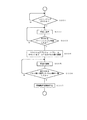
図22は、ウォームフラグによって「WORM」が用途として設定されているテープカセット1に対して記録を行う場合のシステムコントローラ40の処理遷移を説明するフローチャートである。なお、この図に示しているフローチャートはテープストリーマドライブ10にテープカセット1が装填され、リモートメモリチップ4から検出したウォームフラグが「WORM」とされている状態での処理遷移である。
FIG. 22 is a flowchart for explaining a process transition of the
テープカセット1の用途として「WORM」が設定されている状態で、例えばホストコンピュータ40からライトコマンドが供給されると(S001)、まずデータの記録を行うパーティションに対して移動する制御を行う。
この場合、例えば早送り再生を実行し(S002)、この状態で図11で説明した磁気テープ3上に記録されているIDエリアのパーティションIDを検出する(S003)。この早送り再生は、所望するパーティションのパーティションIDが検出されるまで実行する。
When “WORM” is set as the usage of the
In this case, for example, fast-forward playback is executed (S002), and in this state, the partition ID of the ID area recorded on the
ステップS002、S003によって所望するパーティションに到達すると、次にそのパーティションにおける最後のフレームを検出する処理に移行する。
ここで、磁気テープ3において現在位置、すなわち当該パーティションの先頭位置からマキシマムアブソュートフレームカウントで指定されている当該パーティションのフレームまでの距離の算出方法の一例を説明する。
When the desired partition is reached in steps S002 and S003, the process proceeds to a process for detecting the last frame in the partition.
Here, an example of a method for calculating the distance from the current position on the
現在位置から所望する位置までの距離を「L」とした場合、L=マキシマムアブソュートフレームカウント×{(リニアトラックピッチ)×2}となる。但し、この式では、図6に示されているように1フレームは2トラック分に相当するフォーマットを想定しているので、リニアトラックピッチを2倍として計算している。
そして、磁気テープ3の厚さt、リールハブ(2A、2B)の直径をφ、リールハブ(2A、2B)の回転数をnとした場合、距離Lは以下に示す式(1)とされる関係式よって求めることができる。但し、磁気テープ3の厚さtに関する情報は、フィジカルキャラクタリスティックID(図13)から得ることができる。
When the thickness t of the
このような式(1)により、リールハブ2A、2Bを何回転させればマキシマムアブソリュートフレームカウントに対応しているフレームに到達するかを求めることができる。したがって、現在リールFG29C、29Dから出力されているFGパルス数が、式(1)によって求められたリールハブ2A、2Bの回転数nに対応する数になるまで早送り動作を行なうことにより、目標とする位置まで磁気テープ3を進めることができるようになる。
According to the equation (1), it is possible to determine how many times the
このようにして、マキシマムアブソリュートフレームカウントの値をリールFG29C、29Dのパルス数に換算して(S004)、早送り制御によって磁気テープ3を走行させる制御を行う(S005)。この早送り動作に伴って検出されるFGパルス数とステップS004で算出されたパルス数の比較を行い、双方のパルス数が一致した場合に、マキシマムアブソュートフレームカウントの値に対応した位置に到達したことになる。そして、その位置からデータの記録を開始する(S007)。
このように、ステップS004、S005を経ることにより、磁気テープ3上の未記録エリアに移動することができ、この位置から記録を開始することによって、既に記録されているデータは改変されることなく、新たなデータの追加記録を行うことができるようになる。なお、この追加記録が行われることによって、記録されたデータ容量に応じてマキシマムアブソュートフレームカウントも更新されるので、このマキシマムアブソュートフレームカウントに対応した位置を記録の起点とすることで、既に記録されているデータを消去することなく、追加記録を行うことができるようになる。
In this way, the maximum absolute frame count value is converted into the number of pulses of the reels FG29C and 29D (S004), and the
As described above, by going through steps S004 and S005, it is possible to move to an unrecorded area on the
また、ステップS007においてデータの追加記録を行う場合は、記録データと共に、図7(a)に示したブロックのデータエリアA3にカートリッジシリアルナンバを記憶するようにする。これにより、テープカセット1においてリモートメモリチップ4と磁気テープ3を対応させることができ、例えば再生動作を制約するようにすることができるようになる。
When additional recording of data is performed in step S007, the cartridge serial number is stored in the data area A3 of the block shown in FIG. 7A together with the recording data. As a result, the
なお、テープカセット1に対して第一回目の記録を行う場合は、磁気テープの先頭のパーティションの先頭から記録が行われる。
When the first recording is performed on the
図23はテープストリーマドライブ10に磁気テープ3にカートリッジシリアルナンバが記録され、「WORM」とされているテープカセット1が装填された状態で例えば再生動作を行う場合のシステムコントローラ40の処理遷移の一例を説明するフローチャートである。
テープカセット1がテープストリーマドライブ10に装填されると、まずリモートメモリチップ4からカートリッジシリアルナンバを検出し(S101)、さらに磁気テープ3に書き込まれているカートリッジシリアルナンバを検出する(S102)。そして、例えばホストコンピュータ40から例えば再生コマンドが供給されると(S103)、リモートメモリチップ4と磁気テープ3に記録されているカートリッジシリアルナンバの照合を行い(S104)、カートリッジシリアルナンバが一致している判別した場合は(S105)、例えば再生などの所要の動作に移行する制御を行う(S106)。また、カートリッジシリアルナンバが一致していないと判別した場合は、再生動作を実行させないようにして、例えばテープカセット1の排出待機状態に移行する(S107)。
FIG. 23 shows an example of processing transition of the
When the
これにより、テープカートリッジ1において例えばリモートメモリチップ4が交換されて、他のリモートメモリチップ4に挿げ替えられたような場合、データの再生をさせないようにすることができるようになる。したがって、交換された他のリモートメモリチップ4が例えば「汎用」とされていた場合でも、例えば可能な動作を制約することができるので、磁気テープ3に記録されているデータが所定のユーザ以外の外部のユーザに提示されないようにすることができる。
また、同じようにカートリッジシリアルナンバが一致していなかった場合に記録動作を行わないようにすることで、本来「WORM」として磁気テープ3に記録されたデータが改変されないようにすることができるようになる。なお、カートリッジシリアルナンバが一致しなかった場合、データの追加記録に付いては許可するようにするようにしても良い。
As a result, for example, when the
Similarly, by not performing the recording operation when the cartridge serial numbers do not match, the data originally recorded on the
なお、上記実施の形態ではテープカセット1にリモートメモリチップ44が備えられている構成を例で挙げて説明したが、接触型メモリ104が備えられているテープカセット1においても、同様に本発明を適用することができる。
In the above embodiment, the configuration in which the
1 テープカセット、2A,2B リールハブ、3 磁気テープ、4 リモートメモリチップ、5 アンテナ、10 テープストリーマドライブ、11 回転ドラム、12A,12B 記録ヘッド、13A,13B,13C 再生ヘッド、15 システムコントローラ、16 サーボコントローラ、17 メカドライバ、19 RF処理部、20 SCSIインターフェイス、21 圧縮/伸長回路、22 IFコントローラ/ECCフォーマター、23 バッファメモリ、26 SCSIバッファコントローラ、30 リモートメモリインターフェース、33 アンテナ、40 ホストコンピュータ、104 接触型メモリ 1 tape cassette, 2A, 2B reel hub, 3 magnetic tape, 4 remote memory chip, 5 antenna, 10 tape streamer drive, 11 rotating drum, 12A, 12B recording head, 13A, 13B, 13C playback head, 15 system controller, 16 servo Controller, 17 Mechanical driver, 19 RF processor, 20 SCSI interface, 21 Compression / decompression circuit, 22 IF controller / ECC formatter, 23 Buffer memory, 26 SCSI buffer controller, 30 Remote memory interface, 33 Antenna, 40 Host computer, 104 Contact memory
Claims (11)
前記磁気テープへの記録及び/または再生を管理するとともに前記テープカセットを識別するための管理情報を記憶するメモリに対して所要の通信処理を行い、前記管理情報の読み出し及び/または書込みを行なうことができるメモリドライブ手段と、
前記メモリのユーザが改変することができない読み出し専用の領域から、前記磁気テープに、制約なしの記録再生可能、追加記録または再生のみ可能、とする用途を含む前記管理情報の1つである用途識別情報を検出する用途識別情報検出手段と、
前記磁気テープには、前記メモリに記録された前記テープカセットを識別する管理情報と同一のものが記録されており、
所要の動作コマンドに対して、前記用途識別情報と前記磁気テープの前記メモリに記録された前記テープカセットを識別する管理情報とに基づいて前記磁気テープに対する動作を行う制御手段と
を備えているテープドライブ装置。 Tape drive means capable of recording and / or reproducing information on a magnetic tape housed in a tape cassette;
Wherein performs required communication processing for memory for storing management information for identifying the tape cassette, to perform reading and / or writing the management information manages the recording and / or reproducing to the magnetic tape Memory drive means capable of
The use identification which is one of the management information including the use that the memory tape can be recorded / reproduced without restriction, or can only be additionally recorded or reproduced from the read-only area that cannot be modified by the user of the memory. Use identification information detecting means for detecting information;
The same information as the management information for identifying the tape cassette recorded in the memory is recorded on the magnetic tape,
For the required operation command, that it has a control means for performing operations on said magnetic tape on the basis of the tape cassette recorded in the memory of the magnetic tape and the application identification information and management information for identifying the tape Drive device.
前記磁気テープに記憶されている前記テープカセットを識別する管理情報を検出する第二の識別情報検出手段と、
前記第一、第二の識別情報検出手段によって検出された二個の識別情報が一致しているか否かを判別する識別情報判別手段と、
前記識別情報判別手段の判別結果に基づいて特定の動作のみを実行させることができる制御手段と、
を備えた請求項1に記載のテープドライブ装置。 First identification information detecting means for detecting management information for identifying the tape cassette stored in the memory;
Second identification information detecting means for detecting management information for identifying the tape cassette stored in the magnetic tape;
Identification information determination means for determining whether or not two pieces of identification information detected by the first and second identification information detection means match;
Control means capable of causing only a specific operation to be executed based on a determination result of the identification information determination means;
Tape drive according to claim 1 comprising a.
前記テープカセットに備えられ、前記磁気テープに対する記録または再生を管理する
とともに前記テープカセットを識別するための管理情報を記憶するメモリと、を備えた記録媒体において、
前記メモリのユーザが改変することができない読み出し専用の領域には、前記テープカセットに対応した用途を示す、管理情報の1つである用途識別情報が記憶されている記録媒体。 A tape cassette containing magnetic tape;
It is provided in the tape cassette and manages recording or reproduction with respect to the magnetic tape.
And a memory for storing management information for identifying the tape cassette ,
Wherein the read-only area where the user can not modify the memory, said indicating the application that corresponds to the tape cassette, which is one application identification information recording medium that has been stored in the management information.
前記磁気テープへの記録及び/または再生を管理するとともに前記テープカセットを識別するための管理情報を記憶するメモリに対して、所要の通信処理により前記管理情報の読み出し及び/または書込みを行ない、
前記メモリのユーザが改変することができない読み出し専用の領域から、前記磁気テープに、制約なしの記録再生可能、追加記録または再生のみ可能、とする用途を含む前記管理情報の1つである用途識別情報を検出し、
前記磁気テープには、前記メモリに記録された前記テープカセットを識別する管理情報と同一のものが記録されており、
所要の動作コマンドに対して、前記用途識別情報と前記磁気テープの前記メモリに記録された前記テープカセットを識別する管理情報とに基づいて前記磁気テープに対する記録及び/または再生動作を行う記録再生方法。 When recording and / or reproducing information on a magnetic tape stored in a tape cassette,
The memory for storing management information for identifying the tape cassette manages the recording and / or reproducing to the magnetic tape, performs read and / or write the management information by the required communication processing,
The use identification which is one of the management information including the use that the memory tape can be recorded / reproduced without restriction, or can only be additionally recorded or reproduced from the read-only area that cannot be modified by the user of the memory. Detect information,
The same information as the management information for identifying the tape cassette recorded in the memory is recorded on the magnetic tape,
For the required operation command, the application identification information and the recording and / or reproducing operation of intends line recording reproduction on the magnetic tape on the basis of the management information identifying the tape cassette recorded in the memory of the magnetic tape Method.
前記磁気テープに記憶されている前記テープカセットを識別する管理情報を検出する第二の識別情報検出方法と、
前記第一、第二の識別情報検出手段によって検出された二個の識別情報が一致しているか否かを判別する識別情報判別方法と、
前記識別情報判別方法による判別結果に基づいて特定の動作のみを実行させることができる制御方法と、
を備えた請求項8に記載の記録再生方法。 A first identification information detection method for detecting management information for identifying the tape cassette stored in the memory;
A second identification information detection method for detecting management information for identifying the tape cassette stored in the magnetic tape;
An identification information determination method for determining whether or not two pieces of identification information detected by the first and second identification information detection means match;
A control method capable of causing only a specific operation to be executed based on a determination result by the identification information determination method;
Recording and reproduction method according to claim 8 comprising a.
Priority Applications (1)
| Application Number | Priority Date | Filing Date | Title |
|---|---|---|---|
| JP2008200148A JP4766085B2 (en) | 2008-08-01 | 2008-08-01 | Tape drive device, recording medium, and recording / reproducing method |
Applications Claiming Priority (1)
| Application Number | Priority Date | Filing Date | Title |
|---|---|---|---|
| JP2008200148A JP4766085B2 (en) | 2008-08-01 | 2008-08-01 | Tape drive device, recording medium, and recording / reproducing method |
Related Parent Applications (1)
| Application Number | Title | Priority Date | Filing Date |
|---|---|---|---|
| JP07204299A Division JP4672824B2 (en) | 1999-03-17 | 1999-03-17 | Tape drive device, recording medium |
Publications (2)
| Publication Number | Publication Date |
|---|---|
| JP2008300031A JP2008300031A (en) | 2008-12-11 |
| JP4766085B2 true JP4766085B2 (en) | 2011-09-07 |
Family
ID=40173378
Family Applications (1)
| Application Number | Title | Priority Date | Filing Date |
|---|---|---|---|
| JP2008200148A Expired - Lifetime JP4766085B2 (en) | 2008-08-01 | 2008-08-01 | Tape drive device, recording medium, and recording / reproducing method |
Country Status (1)
| Country | Link |
|---|---|
| JP (1) | JP4766085B2 (en) |
Family Cites Families (4)
| Publication number | Priority date | Publication date | Assignee | Title |
|---|---|---|---|---|
| JPH04181583A (en) * | 1990-11-15 | 1992-06-29 | Hitachi Ltd | Recording medium and recording management system and data processing device |
| US5265082A (en) * | 1991-10-03 | 1993-11-23 | International Business Machines Corporation | Rewritable media protectable as written-once-only media and system and method for use therewith |
| JP3687165B2 (en) * | 1995-12-20 | 2005-08-24 | ソニー株式会社 | Tape cassette and data recording / reproducing method |
| JPH09259571A (en) * | 1996-03-22 | 1997-10-03 | Canon Inc | Recording/reproducing apparatus |
-
2008
- 2008-08-01 JP JP2008200148A patent/JP4766085B2/en not_active Expired - Lifetime
Also Published As
| Publication number | Publication date |
|---|---|
| JP2008300031A (en) | 2008-12-11 |
Similar Documents
| Publication | Publication Date | Title |
|---|---|---|
| JP4672824B2 (en) | Tape drive device, recording medium | |
| US6611394B1 (en) | Recording medium, tape drive, and method for identifying type of recording medium | |
| US6970317B2 (en) | Recording medium control method and recording medium adapter | |
| US6535344B1 (en) | Tape drive unit and recording medium | |
| JP4099886B2 (en) | Recording medium and tape drive device | |
| JP4158258B2 (en) | Tape drive device, recording medium | |
| JP2000113640A (en) | Tape drive and recording medium | |
| US7103741B2 (en) | Tape drive apparatus and recording and/or reproducing method | |
| US6643086B1 (en) | Tape driving apparatus | |
| JP3841050B2 (en) | Tape drive device and recording / reproducing method | |
| JP2000173243A (en) | Tape driving device and record medium | |
| JP2000182293A (en) | Tape drive device and recording medium | |
| JP3894315B2 (en) | Tape drive device and recording / reproducing method | |
| US6621650B1 (en) | Recording medium and tape driving apparatus | |
| JP2000173244A (en) | Record medium and tape drive device | |
| JP4766085B2 (en) | Tape drive device, recording medium, and recording / reproducing method | |
| EP1017057B1 (en) | Tape drive unit | |
| JP4513186B2 (en) | Information recording / reproducing device | |
| JP2000187905A (en) | Tape driving device and recording medium | |
| JP4513187B2 (en) | Identification method of tape cassette | |
| JP2000173241A (en) | Record medium and tape driver | |
| JP2002074893A (en) | Tape cassette, device for manufacturing tape cassette, tape drive | |
| JP2000113653A (en) | Tape drive, recording medium | |
| JP2002074902A (en) | Tape drive and information processing system | |
| JP2000100151A (en) | Tape drive device |
Legal Events
| Date | Code | Title | Description |
|---|---|---|---|
| A131 | Notification of reasons for refusal |
Free format text: JAPANESE INTERMEDIATE CODE: A131 Effective date: 20101228 |
|
| A521 | Written amendment |
Free format text: JAPANESE INTERMEDIATE CODE: A523 Effective date: 20110221 |
|
| A01 | Written decision to grant a patent or to grant a registration (utility model) |
Free format text: JAPANESE INTERMEDIATE CODE: A01 Effective date: 20110517 |
|
| A61 | First payment of annual fees (during grant procedure) |
Free format text: JAPANESE INTERMEDIATE CODE: A61 Effective date: 20110530 |
|
| FPAY | Renewal fee payment (event date is renewal date of database) |
Free format text: PAYMENT UNTIL: 20140624 Year of fee payment: 3 |
|
| R250 | Receipt of annual fees |
Free format text: JAPANESE INTERMEDIATE CODE: R250 |
|
| R250 | Receipt of annual fees |
Free format text: JAPANESE INTERMEDIATE CODE: R250 |
|
| R250 | Receipt of annual fees |
Free format text: JAPANESE INTERMEDIATE CODE: R250 |
|
| R250 | Receipt of annual fees |
Free format text: JAPANESE INTERMEDIATE CODE: R250 |
|
| R250 | Receipt of annual fees |
Free format text: JAPANESE INTERMEDIATE CODE: R250 |
|
| EXPY | Cancellation because of completion of term |