JP4765980B2 - Communication network system - Google Patents
Communication network system Download PDFInfo
- Publication number
- JP4765980B2 JP4765980B2 JP2007090213A JP2007090213A JP4765980B2 JP 4765980 B2 JP4765980 B2 JP 4765980B2 JP 2007090213 A JP2007090213 A JP 2007090213A JP 2007090213 A JP2007090213 A JP 2007090213A JP 4765980 B2 JP4765980 B2 JP 4765980B2
- Authority
- JP
- Japan
- Prior art keywords
- packet
- communication path
- service
- network system
- communication network
- Prior art date
- Legal status (The legal status is an assumption and is not a legal conclusion. Google has not performed a legal analysis and makes no representation as to the accuracy of the status listed.)
- Expired - Fee Related
Links
Images


Classifications
-
- H—ELECTRICITY
- H04—ELECTRIC COMMUNICATION TECHNIQUE
- H04Q—SELECTING
- H04Q11/00—Selecting arrangements for multiplex systems
- H04Q11/0001—Selecting arrangements for multiplex systems using optical switching
- H04Q11/0062—Network aspects
-
- H—ELECTRICITY
- H04—ELECTRIC COMMUNICATION TECHNIQUE
- H04J—MULTIPLEX COMMUNICATION
- H04J14/00—Optical multiplex systems
- H04J14/02—Wavelength-division multiplex systems
- H04J14/0227—Operation, administration, maintenance or provisioning [OAMP] of WDM networks, e.g. media access, routing or wavelength allocation
- H04J14/0228—Wavelength allocation for communications one-to-all, e.g. broadcasting wavelengths
- H04J14/023—Wavelength allocation for communications one-to-all, e.g. broadcasting wavelengths in WDM passive optical networks [WDM-PON]
- H04J14/0232—Wavelength allocation for communications one-to-all, e.g. broadcasting wavelengths in WDM passive optical networks [WDM-PON] for downstream transmission
-
- H—ELECTRICITY
- H04—ELECTRIC COMMUNICATION TECHNIQUE
- H04J—MULTIPLEX COMMUNICATION
- H04J14/00—Optical multiplex systems
- H04J14/02—Wavelength-division multiplex systems
- H04J14/0227—Operation, administration, maintenance or provisioning [OAMP] of WDM networks, e.g. media access, routing or wavelength allocation
- H04J14/0241—Wavelength allocation for communications one-to-one, e.g. unicasting wavelengths
- H04J14/0242—Wavelength allocation for communications one-to-one, e.g. unicasting wavelengths in WDM-PON
- H04J14/0245—Wavelength allocation for communications one-to-one, e.g. unicasting wavelengths in WDM-PON for downstream transmission, e.g. optical line terminal [OLT] to ONU
-
- H—ELECTRICITY
- H04—ELECTRIC COMMUNICATION TECHNIQUE
- H04J—MULTIPLEX COMMUNICATION
- H04J14/00—Optical multiplex systems
- H04J14/02—Wavelength-division multiplex systems
- H04J14/0227—Operation, administration, maintenance or provisioning [OAMP] of WDM networks, e.g. media access, routing or wavelength allocation
- H04J14/0241—Wavelength allocation for communications one-to-one, e.g. unicasting wavelengths
- H04J14/0242—Wavelength allocation for communications one-to-one, e.g. unicasting wavelengths in WDM-PON
- H04J14/0249—Wavelength allocation for communications one-to-one, e.g. unicasting wavelengths in WDM-PON for upstream transmission, e.g. ONU-to-OLT or ONU-to-ONU
-
- H—ELECTRICITY
- H04—ELECTRIC COMMUNICATION TECHNIQUE
- H04L—TRANSMISSION OF DIGITAL INFORMATION, e.g. TELEGRAPHIC COMMUNICATION
- H04L41/00—Arrangements for maintenance, administration or management of data switching networks, e.g. of packet switching networks
- H04L41/50—Network service management, e.g. ensuring proper service fulfilment according to agreements
- H04L41/5041—Network service management, e.g. ensuring proper service fulfilment according to agreements characterised by the time relationship between creation and deployment of a service
- H04L41/5045—Making service definitions prior to deployment
-
- H—ELECTRICITY
- H04—ELECTRIC COMMUNICATION TECHNIQUE
- H04Q—SELECTING
- H04Q11/00—Selecting arrangements for multiplex systems
- H04Q11/0001—Selecting arrangements for multiplex systems using optical switching
- H04Q11/0062—Network aspects
- H04Q2011/0077—Labelling aspects, e.g. multiprotocol label switching [MPLS], G-MPLS, MPAS
-
- H—ELECTRICITY
- H04—ELECTRIC COMMUNICATION TECHNIQUE
- H04Q—SELECTING
- H04Q11/00—Selecting arrangements for multiplex systems
- H04Q11/0001—Selecting arrangements for multiplex systems using optical switching
- H04Q11/0062—Network aspects
- H04Q2011/0079—Operation or maintenance aspects
-
- H—ELECTRICITY
- H04—ELECTRIC COMMUNICATION TECHNIQUE
- H04Q—SELECTING
- H04Q11/00—Selecting arrangements for multiplex systems
- H04Q11/0001—Selecting arrangements for multiplex systems using optical switching
- H04Q11/0062—Network aspects
- H04Q2011/0079—Operation or maintenance aspects
- H04Q2011/0081—Fault tolerance; Redundancy; Recovery; Reconfigurability
-
- H—ELECTRICITY
- H04—ELECTRIC COMMUNICATION TECHNIQUE
- H04Q—SELECTING
- H04Q11/00—Selecting arrangements for multiplex systems
- H04Q11/0001—Selecting arrangements for multiplex systems using optical switching
- H04Q11/0062—Network aspects
- H04Q2011/0088—Signalling aspects
Description
通信路を確立する通信ネットワークにおける、通信路確立制御方式に関する。 The present invention relates to a communication path establishment control method in a communication network that establishes a communication path.
特に、管理ドメインまたは管理対象レイヤが複数存在する通信ネットワークにおいて、管理ドメインを跨って、或いはレイヤを跨って、通信路を確立する場合の通信路確立制御方式に関する。 More particularly, the present invention relates to a communication path establishment control method for establishing a communication path across management domains or across layers in a communication network having a plurality of management domains or management target layers.
通信ネットワークに通信路を動的に設定するための技術として、MPLS(IETF, RFC3031, E. Rosen他, “Multiprotocol Label Switching Architecture”)、GMPLS(IETF, RFC3945, Eric Mannie他, "Generalized Multi-Protocol Label Switching Architecture")等の技術がある。本技術は、GMPLS RSVP−TE(IETF, RFC3473, L. Berger他, "Generalized Multi-Protocol Label Switching (GMPLS) Signaling Resource ReserVation Protocol-Traffic Engineering (RSVP-TE) Extensions")等のシグナリングプロトコルにより、波長スイッチや時分割多重装置やパケットスイッチ等のネットワーク装置により構成された通信ネットワーク上に、仮想的な通信路であるところのLSP(Label Switched Path)を設定する。 Technologies for dynamically setting communication paths in communication networks include MPLS (IETF, RFC3031, E. Rosen et al., “Multiprotocol Label Switching Architecture”), GMPLS (IETF, RFC3945, Eric Mannie et al., “Generalized Multi-Protocol Label Switching Architecture "). This technology uses a signaling protocol such as GMPLS RSVP-TE (IETF, RFC3473, L. Berger et al., "Generalized Multi-Protocol Label Switching (GMPLS) Signaling Resource ReserVation Protocol-Traffic Engineering (RSVP-TE) Extensions")). An LSP (Label Switched Path), which is a virtual communication path, is set on a communication network configured by a network device such as a switch, a time division multiplexing device, or a packet switch.
GMPLSネットワークが、複数のレイヤ又は複数の管理ドメインによって構成される場合に、レイヤ又は管理ドメインを跨った通信路をシグナリングにより確立する方式として、特許文献1記載の技術や非特許文献1記載の技術が知られている。
When a GMPLS network is configured by a plurality of layers or a plurality of management domains, as a method of establishing a communication path across the layers or the management domains by signaling, a technique described in
特許文献1記載の技術によれば、RSVP-TEにより通信路を確立する際に、各通信路を利用するサービス毎に、通信路が利用するリンク(すなわち下位レイヤの通信路)を決定することが可能となる。具体的には、下位レイヤの通信路にサービス識別子を予め付与しておき、上位レイヤのエッジノードがサービス識別子を載せて通信路確立要求を発行する。レイヤ境界のノードは、選択可能なリンクの内、リンクが保持するサービス識別子が、受信した通信路確立要求に含まれるサービス識別子に一致するリンクを選択する。
According to the technique described in
非特許文献1記載の技術は、第一の管理ドメイン(以下ドメイン1)内のノードと、第二の管理ドメイン(以下ドメイン2)内のノードの間に、GMPLSにより通信路を確立する際、各々のドメインを管理するPCE(Path Computation Element)と呼ばれるマネージャ間の、協調処理により通信路の経路を決定する手段を提供する。
The technology described in
具体的には、起点ノードがドメイン1のPCE(以下PCE1)に経路計算を要求すると、PCE1はドメイン1内の区間(以下区間1)について、通信路の経路を計算し、引き続きPCE2に対して、ドメイン2内の区間(以下区間2)について通信路の経路の計算を要求する。PCE2は、区間2の計算結果に対応するキー情報(Path Key)をPCE1に対して返す。PCE1は、区間1の経路と区間2のPath Keyとを、起点ノードに返す。
Specifically, when the origin node requests a route calculation from the
起点ノードは、区間1の経路と区間2のPath Keyとを載せた、通信路確立要求を発行し、ドメイン1とドメイン2の間の境界ノードは、受け取ったPath Keyを用いてPCE2に問い合わせることで、区間2の経路を取得し、区間2について通信路を確立する。
The origin node issues a communication path establishment request with the route of
通信路を確立しようとする際に、ネットワーク設計者がその都度判断することなく、自動的に通信路の保守要件及びネットワーク資源の保守条件を考慮して、通信路が各ホップで使用するリンクを決定することを可能とする。また、サービス種別や保守要件毎に異なる、レイヤ間や管理ドメインをまたがって通信路を接続する際のアダプテーション(各種接続機能)を自動的に設定可能とする。 When trying to establish a communication path, the network designer automatically considers the maintenance requirements of the communication path and the maintenance conditions of the network resources without making a judgment each time. Make it possible to decide. In addition, adaptation (various connection functions) for connecting communication paths between layers and across management domains, which is different for each service type and maintenance requirement, can be automatically set.
ここでネットワーク資源の保守条件とは、通信路が使用するデータスイッチやネットワークインタフェース、各ホップのリンク等のネットワーク資源の、保守に関する属性であり、計画工事の時間帯、障害時の交換対応時間帯、定期交換対象有無、保守担当者、製造ベンダ、予備品有無、MTBF(Mean Time Between Failure)、MTTR(Mean Time To Repair)、物品番号、物品のバージョン番号、障害切り分け試験機能有無、賠償責任保険の加入有無、無償交換保証契約有無、などを含む。 Here, the network resource maintenance conditions are attributes related to maintenance of network resources such as data switches, network interfaces, and links of each hop used by the communication path. , Regular replacement target, maintenance personnel, manufacturing vendor, spare parts presence, MTBF (Mean Time Between Failure), MTTR (Mean Time To Repair), article number, article version number, fault isolation test function, liability insurance Including the presence or absence of, and the presence or absence of a free replacement guarantee contract.
通信路の保守要件とは、サービスを提供する通信路が使用する、ネットワーク資源が満たすべき保守条件であり、前記保守に関する属性に対する制約条件式で表現される。 The communication path maintenance requirement is a maintenance condition to be satisfied by the network resource used by the communication path providing the service, and is expressed by a constraint condition expression for the attribute relating to the maintenance.
特許文献1記載の技術によれば、あるレイヤの通信路が使用する、下位レイヤの通信路を、サービス識別子毎に制御することが可能となる。しかしながら、その制御はサービス識別子の比較に基づくため、同じサービスであるならば、保守要件が異なっていても、同じ下位レイヤ通信路に収容されてしまう可能性がある。例えば、「広域LANサービス100Mbps」という同じサービスであるならば、日中のサービス途断が許容されない金融業向けサービスと、夜間〜深夜のサービス途断が許容されないTV放送アクセス回線とが、同一の下位レイヤ通信路に収容されることがあり得る。その為、下位レイヤにおける設備更改などの保守作業の時間が制約を受ける。
According to the technique described in
また特許文献1記載の技術は、アダプテーションを制御する方法を規定してはいない。アダプテーションもまた保守要件と同様多種多様であり、同様の問題が発生すると考えられる。
Further, the technique described in
非特許文献1記載の技術は、ドメイン1とドメイン2が、各々のドメイン内のトポロジを互いに隠蔽することが主な目的であり、本発明が解決しようとする課題と直接の関連性はない。しかし、特許文献1と組み合わせ、さらにPCE2がアダプテーションもまた決定するようにすることで、GMPLSシグナリングで運ぶデータサイズを小さくすることが可能と考えられる。しかしながら、制御シーケンスが複雑となることが、新たな課題となる。
The technology described in Non-Patent
本発明は、制御シーケンスを煩雑にすることなく、通信路が各ホップで使用するリンクと、管理ドメイン或いはレイヤ境界でのアダプテーションを、サービス種別や保守要件に応じて適切に自動選択することを目的とする。 An object of the present invention is to automatically and appropriately select a link used in each hop of a communication path and an adaptation at a management domain or a layer boundary without complicating a control sequence according to a service type and maintenance requirements. And
本発明では、第一に、提供しようとするサービスの識別子及び、サービスの属性を、通信路の確立制御メッセージに載せて、パス確立を要求する手段を、起点ノードに設ける。 In the present invention, first, means for requesting path establishment by placing the identifier of the service to be provided and the attribute of the service in the communication path establishment control message is provided at the origin node.
第二に、サービス識別子及び/又はサービスの属性を元に、通信路の保守要件及びアダプテーションを決定する手段を、各ノードに設ける。各ノードは、パス確立制御メッセージを受信した際に、前記通信路の保守要件及びアダプテーションを決定する手段を用いて、受信したパス確立制御メッセージに含まれるサービスの識別子及び/又はサービス固有の属性を評価することで、通信路の保守要件及び/又はアダプテーションを決定する。 Second, each node is provided with means for determining maintenance requirements and adaptation of the communication path based on the service identifier and / or service attribute. Each node, when receiving the path establishment control message, uses the means for determining the maintenance requirements and adaptation of the communication path to set the service identifier and / or service-specific attributes included in the received path establishment control message. The evaluation determines the maintenance requirements and / or adaptation of the channel.
第三に、各ノードやノード間のリンク等のネットワーク資源の保守条件を保持する手段を各ノードに設け、更に、ネットワーク資源の保守条件と前記通信路の保守要件とを比較することで、前記保守要件を満足可能なリンクやノードを決定する。決定したリンク、ノード、アダプテーションを、スイッチ及び/又はインタフェースの動作パラメータとして設定する。 Third, each node and a means for holding maintenance conditions for network resources such as links between the nodes are provided in each node, and further, by comparing the maintenance conditions for the network resources and the maintenance requirements for the communication path, Determine links and nodes that can satisfy maintenance requirements. The determined link, node, and adaptation are set as operation parameters of the switch and / or interface.
本発明によると、サービス種別と、各サービス固有の属性情報を、通信路確立要求時に通信路毎に、レイヤ間や管理ドメイン間で交換可能となる。そのため、レイヤ間や管理ドメイン間で予め制御情報をやり取りすることなく、サービス種別やサービスの属性に応じた、保守要件の特定に基づく収容関係の決定や、アダプテーションの決定が可能となる According to the present invention, service types and attribute information unique to each service can be exchanged between layers or management domains for each communication path when a communication path establishment request is made. Therefore, it is possible to determine the accommodation relationship based on the specification of maintenance requirements and to determine the adaptation according to the service type and service attribute without exchanging control information between layers or management domains in advance.
<第1実施形態>
以下、本発明の第1実施形態について説明する。
第1実施形態では、シグナリングプロトコルとして、GMPLS拡張RSVP−TEを用い、リンクステート型ルーティングプロトコルとして、GMPLS拡張OSPF−TEを用いた場合について説明するが、IS−IS("OSI IS-IS Intra-domain Routing Protocol", IETF RFC1142)やGMPLS CR−LDP(IETF RFC3472, "Generalized Multi-Protocol Label Switching (GMPLS) Signaling Constraint-based Routed Label Distribution Protocol (CR-LDP) Extensions")等の他のプロトコルであっても同様に、本実施形態を適用することができる。
<First Embodiment>
The first embodiment of the present invention will be described below.
In the first embodiment, a case where GMPLS extended RSVP-TE is used as a signaling protocol and GMPLS extended OSPF-TE is used as a link state routing protocol will be described. However, IS-IS ("OSI IS-IS Intra- other protocols such as domain Routing Protocol ", IETF RFC1142) and GMPLS CR-LDP (IETF RFC3472," Generalized Multi-Protocol Label Switching (GMPLS) Signaling Constraint-based Routed Label Distribution Protocol (CR-LDP) Extensions "). However, the present embodiment can be similarly applied.
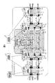
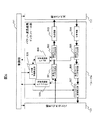
図1は、本発明の第1実施形態のネットワークシステムのブロック図である。 FIG. 1 is a block diagram of a network system according to the first embodiment of this invention.
第1実施形態のネットワークシステムは、確立しようとする通信路61とは異なるリンク上で、GMPLS拡張RSVP−TE及びGMPLS拡張OSPF−TEのメッセージが送受信されるGMPLSネットワークである。 The network system of the first embodiment is a GMPLS network in which GMPLS extended RSVP-TE and GMPLS extended OSPF-TE messages are transmitted and received on a link different from the communication path 61 to be established.
第1実施形態のネットワークシステムは、パケットネットワーク1及び/又は光波長ネットワーク2から構成される。
The network system of the first embodiment includes a
パケットネットワーク1と光波長ネットワーク2は、各々ひとつ以上のGMPLSスイッチと、これらの間でユーザデータをやり取りするためのリンク、同じく制御情報を転送する制御情報転送装置A41〜制御情報転送装置B42から構成される。
Each of the
パケットネットワーク1におけるGMPLSスイッチは、具体的にはパケットスイッチA11〜B12及び/又はパケット-波長連携スイッチA13〜A14であり、リンクはパケットリンク51〜パケットリンク54である。
The GMPLS switch in the
光波長ネットワーク2におけるGMPLSスイッチは、具体的にはパケット-波長連携スイッチA13〜A14及び/又は波長Sw装置A15であり、リンクは波長リンク61〜波長リンク64である。
The GMPLS switch in the
各々のGMPLSスイッチは、ユーザデータをやり取りするための、ひとつ以上のインタフェース部と、ユーザデータの転送先を制御するための、ひとつ以上のスイッチ部と、インタフェース部及びスイッチ部を制御するための、制御部とを持つ。 Each GMPLS switch has one or more interface units for exchanging user data, one or more switch units for controlling the transfer destination of user data, and for controlling the interface unit and the switch unit. It has a control part.
パケットスイッチA11〜B12において、インタフェース部は、具体的にはパケットリンクを終端するパケットインタフェース部である。同様に、スイッチ部はパケットスイッチ部である。 In the packet switches A11 to B12, the interface unit is specifically a packet interface unit that terminates the packet link. Similarly, the switch unit is a packet switch unit.
波長Sw装置A15において、インタフェース部は、具体的には、波長リンクを終端する波長インタフェース部である。同様に、スイッチ部は波長スイッチ部である。 In the wavelength Sw device A15, the interface unit is specifically a wavelength interface unit that terminates the wavelength link. Similarly, the switch unit is a wavelength switch unit.
パケット-波長連携スイッチA13〜A14におけるインタフェース部は、具体的にはパケットリンクを終端するパケットインタフェース部と、波長リンクを終端する波長インタフェース部である。同様に、スイッチ部として、パケットスイッチ部と波長インタフェース部の両方を持つ。 The interface units in the packet-wavelength cooperation switches A13 to A14 are specifically a packet interface unit that terminates the packet link and a wavelength interface unit that terminates the wavelength link. Similarly, the switch unit has both a packet switch unit and a wavelength interface unit.
パケットインタフェース部は、パケットリンクを通じて、隣接するパケットスイッチ又はパケット-波長連携スイッチのパケットインタフェース部との間で、パケット多重のユーザデータをやり取りする。 The packet interface unit exchanges packet-multiplexed user data with a packet interface unit of an adjacent packet switch or packet-wavelength cooperation switch through a packet link.
波長インタフェース部は、波長リンクを通じて、隣接する波長スイッチ又はパケット-波長連携スイッチの波長インタフェース部との間で、波長多重のユーザデータをやり取りする。 The wavelength interface unit exchanges wavelength-multiplexed user data with a wavelength interface unit of an adjacent wavelength switch or packet-wavelength cooperation switch through a wavelength link.
本実施形態のネットワークシステムが、複数レイヤ即ちパケットネットワーク1及び光波長ネットワーク2の両方により構成される場合、パケットネットワーク1はパケットリンクとして、更に、1つ以上のパケットリンク(LSC-LSP)55〜パケットリンク(LSC-LSP)57を伴って構成される。
When the network system of the present embodiment is configured by a plurality of layers, that is, both of the
パケットネットワーク1及び光波長ネットワーク2は、GMPLSに準拠して制御され、ユーザデータは確立されたPSC-LSP31〜33上を伝送される。
The
パケットネットワーク1のA1〜B1間に確立されるPSC-LSP33は、パケットSw装置A11のパケットインタフェース部11bとパケットインタフェース部11d、パケットリンク52、パケット-波長連携Sw装置A13のパケットインタフェース部13bとパケット-波長連携インタフェース部13d、パケットリンク(LSC-LSP)56、パケット-波長連携Sw装置B14のパケット-波長連携インタフェース部14dとパケットインタフェース部14b、パケットリンク54、パケットSw装置B12のパケットインタフェース部12dとパケットインタフェース部12bを通過し、これらのパケット多重により分割される帯域資源を用いて構成される。
The PSC-
PSC-LSP33の一部区間を構成するパケットリンク(LSC-LSP)56は、更に下位レイヤである、波長インタフェース部13g、波長リンク63、波長インタフェース部14gを通過し、これらの波長多重により分割される帯域資源(即ち個々の光波長)を用いて構成される。 The packet link (LSC-LSP) 56 that constitutes a partial section of the PSC-LSP33 passes through the wavelength interface unit 13g, the wavelength link 63, and the wavelength interface unit 14g, which are lower layers, and is divided by these wavelength multiplexing. Band resources (ie, individual optical wavelengths).
同様に、PSC-LSP32は、パケットSw装置A11のパケットインタフェース部11aとパケットインタフェース部11c、パケットリンク51、パケット-波長連携Sw装置A13のパケットインタフェース部13aとパケット-波長連携インタフェース部13e、
パケットリンク(LSC-LSP)57、パケット-波長連携Sw装置B14のパケット-波長連携インタフェース部14eとパケットインタフェース部14a、パケットリンク53、パケットSw装置B12のパケットインタフェース部12cとパケットインタフェース部12cを通過し、これらのパケット多重により分割される帯域資源を用いて構成される。
Similarly, the PSC-
Packet link (LSC-LSP) 57, packet-wavelength link SW unit B14 packet-wavelength link interface unit 14e and packet interface unit 14a,
PSC-LSP32の一部区間を構成するパケットリンク(LSC-LSP)57は、更に下位レイヤである、波長インタフェース部13h、波長リンク64、波長インタフェース部14hを通過し、これらの波長多重により分割される帯域資源(即ち個々の光波長)を用いて構成される。
The packet link (LSC-LSP) 57 that constitutes a partial section of PSC-LSP32 passes through the
更に、PSC-LSP31もまた同様であるが、PSC-LSP31確立前には、パケットリンク(LSC-LSP)55が確立されておらず、パケット-波長連携Sw装置A13のパケット-波長連携インタフェース部13c、パケット-波長連携Sw装置B14のパケット-波長連携インタフェース部14cの運用状態(Operational State)が、非稼動状態(disabled)となっている点が異なる。そのため図1では、波長インタフェース部13f、パケット-波長連携インタフェース部13c、パケット-波長連携インタフェース部14cを、点線で図示している。
Further, PSC-LSP31 is the same, but before PSC-LSP31 is established, packet link (LSC-LSP) 55 is not established, and packet-wavelength
また、パケットリンク(LSC-LSP)55は、更に下位レイヤである、パケット-波長連携Sw装置A13の波長インタフェース部13f、波長リンク61、波長Sw装置A15の波長インタフェース部15bと波長インタフェース部15d、波長リンク62、パケット-波長連携Sw装置B14の波長インタフェース部14fを通過し、これらの波長多重により分割される帯域資源(即ち個々の光波長)を用いて構成される。
Further, the packet link (LSC-LSP) 55 is a lower layer, the
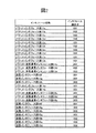
インタフェース部は、あるGMPLSスイッチ中では、インタフェース識別子によって識別される。通信ネットワーク2の中ではルータ識別子とインタフェース識別子の組により、一意に識別される。図1中のインタフェース部のインタフェース識別子を図2に示す。例えば、パケットインタフェース部11aのインタフェース識別子は101である。また、パケットインタフェース部11aが属するパケットSw装置A11のルータ識別子が10.0.1.1であるので、[10.0.1.1, 101]という組により、パケットネットワーク1及び光波長ネットワーク2の中で一意に識別される。
The interface unit is identified by an interface identifier in a GMPLS switch. In the
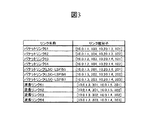
リンクは、リンク識別子によって、ネットワークシステムの中で一意に識別される。リンク識別子は、該リンクが接続するインタフェース部の、ルータ識別子とインタフェース識別子の組である。図1中のリンクのリンク識別子を図3に示す。例えば、パケットリンク51は、[10.0.1.1, 103]と[10.20.1.3, 101]とを接続しているため、そのリンク識別子は[10.0.1.1, 103, 10.20.1.3, 101]となる。 A link is uniquely identified in the network system by a link identifier. The link identifier is a set of a router identifier and an interface identifier of the interface unit to which the link is connected. FIG. 3 shows the link identifiers of the links in FIG. For example, since the packet link 51 connects [10.0.1.1, 103] and [10.20.1.3, 101], the link identifier is [10.0.1.1, 103, 10.20.1.3, 101].
通信路確立要求装置71は、操作端末、装置管理システム(Element Management System)のネットワーク管理システム、ストレージ管理サーバやビデオサーバ等のアプリケーションシステム等であり、PSC-LSP31〜33の確立を要求する。図1では1台のみ示しているが、確立する通信路の端点に応じて、任意の台数を設置してもよい。
The communication path
通信路確立要求装置71がパケットネットワーク1に対してPSC-LSPの確立を要求するプロトコルとしては、telnet(IETF, RFC854)等を用いたコマンドの投入、RSVP−TEやO−UNI(Optical Internetworking Forum, User Network Interface (UNI) 1.0 Signaling Specification)等のシグナリングプロトコル、HTTP(IETF RFC1945)やSIP(IETF RFC2543)、RTSP(IETF RFC2326)等のアプリケーションプロトコル、SOAP(World Wide Web Consortium, SOAP Version 1.2)やIIOP(Object Management Group, CORBA(TM)/IIOP(TM) Specification)等のリモートプロシージャコールプロトコル等を使用可能である。
Protocols for requesting establishment of PSC-LSP from the
通信路確立要求装置71がPSC-LSPの確立を要求すると、パケットSw装置A11、パケット-波長連携Sw装置A13、パケット-波長連携Sw装置B14及びパケットSw装置B12が、シグナリングプロトコル(例えば、GMPLS拡張RSVP−TE)によるメッセージを互いに送受信し、各スイッチ内のパケットスイッチ部の状態を更新することによって、PSC-LSP31〜33が確立される。前提となるパケットリンク(LSC-LSP)55〜57が未確立である場合、必要に応じて、パケット-波長連携Sw装置A13、波長Sw装置A15、パケット-波長連携Sw装置B14が、シグナリングプロトコルによるメッセージを互いに送受信し、各スイッチ内の波長スイッチ部133,153,143の状態を更新することによって、パケットリンク(LSC-LSP)55〜57が確立される。
When the communication path
パケットスイッチA11〜B12、パケット-波長連携スイッチA13〜A14、波長Sw装置A15は、ルーティングプロトコルの一つであるGMPLS拡張OSPF−TEのメッセージを送受信することによって、ネットワークのトポロジを入手することができる。GMPLS拡張OSPF−TEのメッセージは、制御情報転送装置A41及び/又は制御情報転送装置B42を介してやり取りされる。 The packet switches A11 to B12, the packet-wavelength cooperation switches A13 to A14, and the wavelength Sw device A15 can obtain the network topology by transmitting and receiving messages of GMPLS extended OSPF-TE which is one of the routing protocols. . The GMPLS extended OSPF-TE message is exchanged via the control information transfer device A41 and / or the control information transfer device B42.
GMPLSでは、ユーザデータとシグナリングプロトコルとは、同じ経路上で転送される必要はない。本実施形態では、例えばPSC-LSP33上のユーザデータはパケットSw装置A11、パケット-波長連携スイッチA13〜A14、パケットSw装置B12(通信インタフェース11b, 11d, 13b, 13d, 14d, 14b, 12d、12b)を経由して転送されるのに対し、GMPLS拡張RSVP−TEやGMPLS拡張OSPF−TEのメッセージは、制御情報転送装置A41及び/又は制御情報転送装置B42を経由して転送される。
In GMPLS, user data and signaling protocol do not need to be transferred on the same path. In the present embodiment, for example, user data on the PSC-
また、GMPLS拡張RSVP-TEやGMPLS拡張OSPF-TEのメッセージは、Generic Routing Encapsulation(IETF RFC2784)等のトンネリングプロトコルによりカプセル化されていてもよい。 Further, GMPLS extended RSVP-TE and GMPLS extended OSPF-TE messages may be encapsulated by a tunneling protocol such as Generic Routing Encapsulation (IETF RFC2784).
制御情報転送装置A41及び制御情報転送装置B42は、IP(Internet Protocol)ルータやIEEE 802.3D MACブリッジ等の、パケット転送機能を持つ装置である。 The control information transfer device A41 and the control information transfer device B42 are devices having a packet transfer function, such as an IP (Internet Protocol) router and an IEEE 802.3D MAC bridge.
次に、各GMPLSスイッチのハードウェア構成と動作について、説明する。 Next, the hardware configuration and operation of each GMPLS switch will be described.
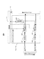
図4は、パケットインタフェース部11a〜11dのブロック図である。
パケットインタフェース部11a〜11dは、光受信器401、受信パケットヘッダ解析部402、送信パケットヘッダ生成部403、光送信器404及びパケットレイヤ障害管理部405から構成される。
FIG. 4 is a block diagram of the packet interface units 11a to 11d.
The packet interface units 11a to 11d include an
光受信器401は、他のGMPLSスイッチから光信号を受信し、パケットデータにデコードして受信パケットヘッダ解析部402に送る。受信パケットヘッダ解析部402は、受信したパケットのヘッダ情報により、パケットスイッチ部112が解釈可能な内部的な転送先情報を生成し、パケットスイッチ部112に送る。
The
パケットスイッチ部112は、GMPLS拡張RSVP-TEメッセージのやり取りによって決定されたパケットクロスコネクト情報に基づき、パケットを送出すべきインタフェース部を決定し、決定されたインタフェース部にパケットを転送する。
The
転送されるパケットは、パケットスイッチ部112から送信パケットヘッダ生成部403に渡される。送信パケットヘッダ生成部403は、次ホップへの転送に必要なヘッダ情報を生成し、光送信器404を介して、光信号として、隣接のGMPLSスイッチのパケットインタフェース部に送信する。
The transferred packet is passed from the
パケットレイヤ障害管理部405は、制御部111からの指示に基づいて、パケットレイヤに於ける障害有無を診断し、障害有無情報を制御部111に通知する。障害有無を診断する単位は、確立されたPSC-LSP単位や、パケットリンク、或いは更に下位レイヤの信号単位などである。
Based on an instruction from the control unit 111, the packet layer
障害有無を診断する手段としては、光信号のパワーロスやフレーム同期外れ、CRC(Cyclic Redundancy Check)等による符号検査等の受動的な検査方法や、Ethernet-OAM(ITU-T Y.1731, IEEE802.1ag)、MPLS-OAM(ITU-T, Y.1711)、ICMP(IETF, RFC0792)等の障害検出信号のやり取りによる、能動的な検査方法を使用可能である。 As means for diagnosing the presence or absence of failures, passive inspection methods such as optical signal power loss, loss of frame synchronization, code inspection using CRC (Cyclic Redundancy Check), etc., Ethernet-OAM (ITU-T Y.1731, IEEE802. 1ag), MPLS-OAM (ITU-T, Y.1711), ICMP (IETF, RFC0792), and other active inspection methods by exchanging fault detection signals can be used.
受信パケットヘッダ解析部402や送信パケットヘッダ生成部403はまた、パケットのカプセル化処理、トラフィックフローの分離/統合、QoSマッピング、警報転送処理、符号変換等の、ネットワーク間のアダプテーション(Adaptation)処理を行っても良い。適合化処理もまた、制御部111からの指示に基づいて、制御される。
The reception packet
パケットのカプセル化処理としては、MPLS Label Stack Encoding(IETF, RFC3032)やPseudo Wire Emulation(PWE3; IETF, RFC3985)、Generic Framing Procedure(GFP; ITU-T, G.7041)等が考えられる。 As packet encapsulation processing, MPLS Label Stack Encoding (IETF, RFC3032), Pseudo Wire Emulation (PWE3; IETF, RFC3985), Generic Framing Procedure (GFP; ITU-T, G.7041), and the like can be considered.
QoS処理としては、DiffServ(“Differentiated Services and Tunnels”, IETF, RFC2983)のDSCP値とIEEE 802.1Dのプライオリティ値のマッピング、TrTCM(“A Two Rate Three Color Marker”, IETF, RFC2698)によるトラフィック量に基づくDSCP値決定、L2〜L7ヘッダ情報に基づく選択的パケット廃棄、uRPF(Reverse Path Forwarding)による選択的パケット廃棄などが考えられる。 QoS processing includes mapping the DSCP value of DiffServ (“Differentiated Services and Tunnels”, IETF, RFC2983) and the priority value of IEEE 802.1D, and the traffic volume by TrTCM (“A Two Rate Three Color Marker”, IETF, RFC2698). Based on the DSCP value determination, selective packet discard based on L2 to L7 header information, selective packet discard by uRPF (Reverse Path Forwarding), and the like.
トラフィックフローの分離/統合処理としては、OTN(Optical Transport Network)/SDH(Synchronous Digital Hierarchy)/MPLS伝送路のパスプロテクション機能、Virtual conCATenation(VCAT; ITU-T, G.783), Link Capacity Adjustment Scheme(LCAS; ITU-T, G.7042)、リンクアグリゲーション、L2〜L7ヘッダ情報に基づくポリシールーティングなどが考えられる。 Traffic flow separation / integration processing includes OTN (Optical Transport Network) / SDH (Synchronous Digital Hierarchy) / MPLS transmission path protection function, Virtual conCATenation (VCAT; ITU-T, G.783), Link Capacity Adjustment Scheme (LCAS; ITU-T, G.7042), link aggregation, policy routing based on L2 to L7 header information, and the like can be considered.
警報転送処理としては、MPLS-OAMで検出した障害警報をトリガに、Ethernet-OAMの障害情報を新たに発行する、などが考えられる。 As alarm transfer processing, it is conceivable to newly issue Ethernet-OAM failure information triggered by a failure alarm detected by MPLS-OAM.
符号変換処理としては、誤り訂正符号の挿入、プロトコル変換、データ圧縮伸張、メディアストリームのトランスコードなどが考えられる。 As code conversion processing, error correction code insertion, protocol conversion, data compression / decompression, media stream transcoding, and the like can be considered.
パケットSw装置B12、パケット-波長連携スイッチA13〜A14のパケットインタフェース部の構成や動作また、パケットインタフェース部11a〜11dと同等である。 The configuration and operation of the packet interface unit of the packet Sw device B12 and the packet-wavelength cooperation switches A13 to A14 are the same as the packet interface units 11a to 11d.
図5は、波長Sw装置A15の波長インタフェース部15a〜15dの構成と動作を表すブロック図である。 FIG. 5 is a block diagram showing the configuration and operation of the wavelength interface units 15a to 15d of the wavelength Sw device A15.
波長インタフェース部15a〜15dは、波長変換器60101〜60132、光信号再生器60201〜60232、合波器603、分波器604及び光信号再生器60233〜60264から構成される。
The wavelength interface units 15a to 15d include
分波器604は、隣接の波長スイッチやパケット-波長連携スイッチの波長インタフェース部から受光した、波長多重された光信号を個々の波長成分に分け、各々の光信号再生器60233〜60264に渡す。光信号再生器60233〜60264は、2R(Re-amplification and Re-shaping)又は3R(Re-amplification, Re-shaping and Re-timing)処理により光信号を再生し、波長スイッチ部133に渡す。
The
波長スイッチ部133は、GMPLS拡張RSVP-TEメッセージのやり取りによって決定された、光クロスコネクト情報に基づき、光信号を送出すべきインタフェース部を決定し、決定されたインタフェース部にパケットを転送する。
The
図6は、パケット-波長連携スイッチA13〜A14のパケット-波長連携インタフェース部13c〜13eの構成と動作を表すブロック図である。
FIG. 6 is a block diagram showing the configuration and operation of the packet-
パケット-波長連携インタフェース部13c〜13eは、送信パケットヘッダ生成部501、送信フレームヘッダ生成部502、光送信器503、光受信器504、送信フレームヘッダ生成部505、受信パケットヘッダ解析部506、パケットレイヤ警報挿入部507、光レイヤ障害管理部508、レイヤ間警報転送部509及びパケットレイヤ障害管理部510から構成される。
The packet-wavelength
次に、パケットSw装置A11が持つ制御部111の構成と動作について説明する。 Next, the configuration and operation of the control unit 111 included in the packet sw device A11 will be described.
図7は、パケットスイッチA11〜B12の制御部111のブロック図である。 FIG. 7 is a block diagram of the control unit 111 of the packet switches A11 to B12.
制御部111は、CPU1111、メモリ1112、バスなどの内部通信路1113、通信インタフェース1114、装置制御インタフェース1115及び二次記憶装置1116によって構成される。
The control unit 111 includes a
通信インタフェース1114は、制御情報転送装置に接続され、他のGMPLSスイッチとの間でGMPLS拡張RSVP-TEメッセージをやり取りする。
The
装置制御インタフェース1115は、パケットスイッチ部、パケットインタフェース部と接続され、これらを制御する。
The
また、メモリ1112には、プログラム11121とデータ11122が必要に応じて格納されている。
The
パケットSw装置B12の制御部121もまた、制御部111と同様である。 The control unit 121 of the packet Sw device B12 is also the same as the control unit 111.
波長Sw装置A15の制御部もまた、制御部111と同等であるが、接続先のインタフェース部及びスイッチ部が、各々波長インタフェース部及び波長スイッチ部となる。 The control unit of the wavelength sw device A15 is also equivalent to the control unit 111, but the interface unit and the switch unit to be connected become the wavelength interface unit and the wavelength switch unit, respectively.
パケット-波長連携スイッチA13〜A14の制御部もまた、制御部111と同等であるが、接続先のインタフェース部がパケットインタフェース部と波長インタフェース部、スイッチ部がパケットスイッチ部と波長スイッチ部となる。 The control units of the packet-wavelength cooperation switches A13 to A14 are also the same as the control unit 111, but the connection destination interface unit is the packet interface unit and the wavelength interface unit, and the switch unit is the packet switch unit and the wavelength switch unit.
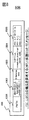
図8Aは、GMPLSスイッチがやり取りする、GMPLS拡張RSVP−TEメッセージ100の内容を示すフォーマット図である。
FIG. 8A is a format diagram showing the contents of the GMPLS extended RSVP-
GMPLS拡張RSVP−TEメッセージ100は、RSVPメッセージ種別1001、セッション識別子1002、サービス識別子1003、サービス属性1004、明示的経路1005、その他のRSVPオブジェクト1_1006、その他のRSVPオブジェクト2_1007及びその他のRSVPオブジェクトn1008を含む。
The GMPLS extended RSVP-
RSVPメッセージ種別1001、セッション識別子1002、明示的経路1005は、RSVP標準に基づくオブジェクトである。
The
GMPLS拡張RSVP−TEメッセージ100には、パス確立要求を意味するPATHメッセージと、パス確立応答及び資源割り当てを意味するRESVメッセージなどがある。RSVPメッセージ種別1001はこれらの種別を表す。
The GMPLS extended RSVP-
セッション識別子1002は、GMPLSにより確立される通信路(LSP; Label Switched Path)を識別するための識別子である。
The
明示的経路1005オブジェクトは、確立しようとする通信路が通過すべき点を、上流のGMPLSスイッチが指定するためのオブジェクトである。
The
サービス識別子1003及びサービス属性1004は、本明細書で導入するオブジェクトであり、確立しようとするパスが提供するサービスの種別と、サービスの詳細を特徴付ける個々のサービス固有の属性である。
The
その他のRSVPオブジェクト1_1006、その他のRSVPオブジェクト2_1007及びその他のRSVPオブジェクトn1008は、RSVP標準に基づく、上記以外のオブジェクトである。
図8Bは、PSC-LSP31を確立する場合に、パケットSw装置A11がパケット-波長連携Sw装置A13に対して発行するパス要求メッセージを示す。
The other RSVP object 1_1006, the other RSVP object 2_1007, and the other RSVP object n1008 are objects other than the above based on the RSVP standard.
FIG. 8B shows a path request message issued by the packet Sw device A11 to the packet-wavelength cooperation Sw device A13 when the PSC-LSP 31 is established.
このパス要求メッセージはパス確立要求であるので、RSVPメッセージ種別1001はPATHとなっている。起点ノード及び終点ノードのルータ識別子が、10.0.1.2及びextId=10.0.1.1であるので、GMPLS標準に基づいて、セッション識別子1002として”10.0.1.2,tunnelId=1,extId=10.0.1.1”が格納されている。
Since this path request message is a path establishment request, the
セッション識別子1002、明示的経路1005には、企業向けサービスであること、VoIPを使用すること、回線がダウンすることを許容可能な時間帯が22:00〜1:00の間であることが、示されている。
The
明示的経路1005は、パスが通過すべき経路を示している。この値は、ネットワークトポロジテーブル8018の情報を用いて、Shortest Path First等の経路探索アルゴリズムにより、通信路経路計算部8019が導いた値による。ネットワークトポロジテーブル8018には、保守要件やアダプテーションに関する情報は格納されていないため、PSC-LSP31のエンドツーエンドに渡って、リンクの詳細を決定することは出来ない。そのため、次ホップである10.0.1.3までのリンクは明示的に指定しているが、ルータ識別子が10.0.1.4と10.0.1.2のノードに至る部分については、ノードの指定にとどまっている。
An
図8Cも同様に、PSC-LSP32を確立する場合に、パケットSw装置A11がパケット-波長連携Sw装置A13に対して発行するパス要求メッセージの内容を示す。PSC-LSP32は企業向けサービスであること、VoIPを使用しないことが、示されている。
Similarly, FIG. 8C shows the contents of a path request message issued by the packet Sw device A11 to the packet-wavelength cooperation Sw device A13 when the PSC-
図8Dも同様に、PSC-LSP33を確立する場合に、パケットSw装置A11がパケット-波長連携Sw装置A13に対して発行するパス要求メッセージの内容を示す。PSC-LSP32はTV放送向けサービスであることが、示されている。
Similarly, FIG. 8D shows the contents of a path request message issued by the packet Sw device A11 to the packet-wavelength cooperation Sw device A13 when the PSC-
図9は、制御部111のソフトウェア構成を示す図である。他のGMPLSスイッチも同様である。
シグナリング処理部8014は、制御メッセージ送受信部8016を介して、他のGMPLSスイッチとGMPLS拡張RSVP-TEメッセージをやり取りする。また、通信路確立要求装置71からのパス確立要求を受け付ける。
FIG. 9 is a diagram illustrating a software configuration of the control unit 111. As illustrated in FIG. The same applies to other GMPLS switches.
The
シグナリング処理部8014が、パス確立要求を通信路確立要求装置71又から受信、或いは上流のGMPLSスイッチからPATHメッセージを受信すると、図15を用いて後に説明する方路決定処理とアダプテーション決定処理が、サービス識別子1003及びサービス属性1004を用いて、次ホップのリンクとアダプテーションを決定する。決定した、次ホップのリンクとアダプテーションは、セッション管理テーブル8020に格納する。更に、GMPLS標準に基づくPATHメッセージ転送処理により、制御メッセージ送受信部8016を介して、下流のGMPLSスイッチに送信する。
When the
決定した、次ホップのリンクが、未確立のリンクである場合、確立する通信路の経路の計算を、通信路経路計算部8019に依頼する。決定した経路に基づいて、シグナリング処理部8014は、自らが起点となる、新たな通信路の確立を要求する。例えば、PSC-LSP31の確立処理中に、未確立であるパケットリンク(LSC-LSP)55を、自らが起点となって、確立を要求する。
When the determined next hop link is an unestablished link, the communication
シグナリング処理部8014が、RESVメッセージを下流のGMPLSスイッチから受信すると、セッション管理テーブル8020に格納されたリンク情報に基づき、クロスコネクション設定値を組み立て、スイッチ部に設定する。また、セッション管理テーブル8020に格納されたアダプテーション情報に基づき、インタフェース部を設定する。
ルーティング処理部8017は、制御メッセージ送受信部8016を介して、他のGMPLSスイッチとGMPLS拡張OSPF-TEメッセージをやり取りする。
When the
The
自らは、リンク属性テーブル8010が保持する、隣接GMPLSスイッチとの間のリンク情報を、GMPLS拡張OSPF-TEにより隣接GMPLSスイッチに送信すると共にネットワークトポロジテーブル8018に格納する。また、隣接GMPLSスイッチから受信したリンク情報をネットワークトポロジテーブル8018に格納すると共に、他の隣接GMPLSスイッチに転送する。これらの動作により、パケットネットワーク1及び光波長ネットワーク2の全てのリンクの情報が、ネットワークトポロジテーブル8018に蓄積され、パケットネットワーク1及び光波長ネットワーク2のトポロジが把握される。
By itself, link information between adjacent GMPLS switches held in the link attribute table 8010 is transmitted to the adjacent GMPLS switch by the GMPLS extended OSPF-TE and stored in the network topology table 8018. Further, the link information received from the adjacent GMPLS switch is stored in the network topology table 8018 and transferred to another adjacent GMPLS switch. Through these operations, information of all links of the
通信路経路計算部8019は、シグナリング処理部8014からの要求に基づき、通信路を確立可能な経路を、ネットワークトポロジテーブル8018に蓄積されたトポロジ情報に基づいて計算する。計算アルゴリズムとしては、SPF(Shortest Path First)などのアルゴリズムが用いられる。
Based on a request from the
シグナリング処理部8014はまた、図15を用いて後に説明する方路決定処理とアダプテーション決定処理により、受信したパス確立要求に含まれるサービス識別子1003及びサービス属性1004を、サービス定義テーブル8011を用いて評価し、確立しようとする通信路の保守要件とアダプテーションを決定する。更に通信路の保守要件を元に、リンク属性テーブル8010を検索し、使用する次ホップのリンクを決定する。
The
各行のサービス識別子条件1101及びサービス属性条件1102を充たすか評価し、条件を充たすならば保守条件及びアダプテーションとして、同じ行の保守要件1103及びアダプテーション1104の値を採用する。
Whether the
図10は、通信路を確立する際に各GMPLSスイッチがやり取りするGMPLS拡張RSVP-TEのメッセージと、各GMPLSスイッチの制御部の処理のシーケンスを表す、シーケンス図である。 FIG. 10 is a sequence diagram showing a GMPLS extended RSVP-TE message exchanged by each GMPLS switch when establishing a communication path and a processing sequence of the control unit of each GMPLS switch.
通信路確立要求装置71が発行したパス確立要求をパケットSw装置A11が受信すると(901)、パケットSw装置A11は、受け取ったサービス識別子及びサービスの属性を元に、サービス定義テーブル8011を用いて、次ホップのリンクの保守要件を決定する(9011)。次に、保守要件を元に、リンク属性テーブル8010を用いて、次ホップのリンクを決定する(9012)。また、サービス識別子及びサービスの属性を元に、サービス定義テーブル8011を用いて、アダプテーションを決定する。決定した、次ホップのリンク、及びアダプテーションは、セッション管理テーブル8020に格納され、後にRESVメッセージを受信した際に用いられる(9071、9072)。引き続き、GMPLS拡張RSVP-TE標準の動作に基づいて、次ホップへPATHメッセージを転送する。この際に、サービス識別子及びサービスの属性は、そのまま転送される。 When the packet Sw device A11 receives the path establishment request issued by the communication path establishment request device 71 (901), the packet Sw device A11 uses the service definition table 8011 based on the received service identifier and service attribute, The maintenance requirements for the next-hop link are determined (9011). Next, based on the maintenance requirements, the link of the next hop is determined using the link attribute table 8010 (9012). Also, the adaptation is determined using the service definition table 8011 based on the service identifier and the service attribute. The determined next hop link and adaptation are stored in the session management table 8020 and used when a RESV message is received later (9071, 9072). Subsequently, the PATH message is transferred to the next hop based on the operation of the GMPLS extended RSVP-TE standard. At this time, the service identifier and the service attribute are transferred as they are.
以後、PATHメッセージの明示的経路に指定された経路に沿って、パケット-波長連携Sw装置A13、パケット-波長連携Sw装置B14、パケットSw装置B12の順に、PATHメッセージが転送され、同様の処理を繰り返す(902,9021〜9023, 903, 9031〜9033,904及び9041〜9043)。
パケットSw装置A11は、要求された通信路の終点であるので、PATHメッセージ受信時の処理(9041〜9043)に引き続き、RESVメッセージ受信時と同等の処理を行う。すなわち、決定されたリンク情報及びアダプテーション情報に基づいて、アダプテーション及びクロスコネクションを、インタフェース部及びスイッチ部に設定する(9044, 9045)。
以後、GMPLS拡張RSVP-TE標準の動作に基づいて、前ホップへRESVメッセージを転送する(905, 906, 907)。経路上の他のGMPLSスイッチもまた、アダプテーション及びクロスコネクションを、インタフェース部及びスイッチ部に設定する(9051, 9052, 9061, 9062,9071, 9072)。
Thereafter, the PATH message is transferred in the order of the packet-wavelength cooperation Sw device A13, the packet-wavelength cooperation Sw device B14, and the packet Sw device B12 along the route specified in the explicit route of the PATH message. Repeat (902, 9021 to 9023, 903, 9031 to 9033, 904 and 9041 to 9043).
Since the packet Sw device A11 is the end point of the requested communication path, the processing equivalent to that at the time of RESV message reception is performed subsequent to the processing at the time of receiving the PATH message (9041 to 9043). That is, based on the determined link information and adaptation information, adaptation and cross connection are set in the interface unit and the switch unit (9044, 9045).
Thereafter, the RESV message is transferred to the previous hop based on the operation of the GMPLS extended RSVP-TE standard (905, 906, 907). Other GMPLS switches on the route also set the adaptation and cross connection to the interface unit and the switch unit (9051, 9052, 9061, 9062, 9071, 9072).
尚、次ホップを決定した際に、次ホップまでの該当リンクが未確立である場合、自らが起点となる新たな通信路確立シーケンスを起動する。例えば、PSC-LSP31確立の過程でパケットリンク(LSC-LSP)55が未確立であることをパケット-波長連携Sw装置A13が検出すると(9022)、パケット-波長連携Sw装置A13は波長Sw装置A15に向けて、パケットリンク(LSC-LSP)55確立のための新たなセッション識別子を生成し、PATHメッセージを波長Sw装置A15に対して送出する。 When the next hop is determined, if a corresponding link up to the next hop is not established, a new communication path establishment sequence starting from itself is started. For example, when the packet-wavelength cooperation Sw device A13 detects that the packet link (LSC-LSP) 55 is not established in the process of establishing the PSC-LSP31 (9022), the packet-wavelength cooperation Sw device A13 Then, a new session identifier for establishing the packet link (LSC-LSP) 55 is generated, and a PATH message is sent to the wavelength Sw device A15.
以上により、パケットSw装置A11〜パケットSw装置B12の間に通信路が確立される。 As a result, a communication path is established between the packet Sw device A11 and the packet Sw device B12.
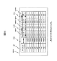
図11は、サービス定義テーブル8011の構成図である。 FIG. 11 is a configuration diagram of the service definition table 8011.
サービス識別子条件1101、サービス属性条件1102、保守要件1103及びアダプテーション1104の各列を含んでいる。
Each column includes a
各行は、受信したパス確立要求に基づき、保守要件1103及びアダプテーション1104を決定する、if-thenルールを示している。
Each line indicates an if-then rule that determines the
図9を用いて既に説明した通り、シグナリング処理部8014は、受信したパス確立要求に含まれるサービス識別子1003及びサービス属性1004を、各行のサービス識別子条件1101及びサービス属性条件1102を充たすか評価し、条件を充たすならば通信路の保守要件及びアダプテーションとして、同じ行の保守要件1103及びアダプテーション1104の値を採用する。
As already described using FIG. 9, the
例えば、図8Bに示したPSC-LSP31のパス確立メッセージに含まれる、セッション識別子1002及び明示的経路1005は、サービス定義テーブル8011の1行目の条件を充たすので、通信路の保守要件は”max_fail_time < 1sec, maintenance_time = acceptable_down_time”となる。これは、サービス断時間が1秒以内であるべきこと、保守時間帯はサービス属性1004記載のacceptable_down_time内(すなわち22:003:00)であるべきことを示している。同様に、アダプテーションは、”notifyFailureDetection = enabled”となる。
For example, since the
同様に、PSC-LSP32については図8Cに示した値を用いて、サービス定義テーブル8011の4行目の条件を、PSC-LSP33については図8Dに示した値を用いて、サービス定義テーブル8011の5行目の条件を、各々満足するので、同じ行の保守要件1103及びアダプテーション1104の値が採用される。
Similarly, for the PSC-LSP32, the value shown in FIG. 8C is used, and the condition of the fourth line of the service definition table 8011 is used. For the PSC-LSP33, the value shown in FIG. Since the conditions on the fifth row are satisfied, the values of the
図12は、リンク属性テーブル8010の構成図である。 FIG. 12 is a configuration diagram of the link attribute table 8010.
リンク属性テーブル8010は、スイッチングケーパビリティ1201、自ノードI/F1202、対向装置ルータ識別子1203、対向装置I/F識別子1204、運用状態1205、下位レイヤセッション識別子1206及びリンク保守条件1207の各列を持つ。
The link attribute table 8010 has columns of
リンク属性テーブル8010の各行の内、スイッチングケーパビリティ1201がPSCのものはパケットリンク1本を、スイッチングケーパビリティ1201がLSCのものは波長リンク1本を、それぞれ表している。
Of each row of the link attribute table 8010, one with a
図中の値は、パケット-波長連携Sw装置A13の例を示している。 The values in the figure show an example of the packet-wavelength cooperation Sw device A13.
下位レイヤセッション識別子1206の値が空欄のものは、下位レイヤがGMPLSによって制御されるLSPではないことを示している。 When the value of the lower layer session identifier 1206 is blank, it indicates that the lower layer is not an LSP controlled by GMPLS.
下位レイヤセッション識別子1206の値に”LSC”のみが格納されているものは、LSC-LSPを確立可能であるが、まだ確立していないことを表している。下位レイヤセッション識別子1206の値に”LSC”及びセッション識別子が格納されているものは、LSC-LSPが既に確立されていることを表している。 A value in which only “LSC” is stored in the value of the lower layer session identifier 1206 indicates that the LSC-LSP can be established but has not yet been established. The value of “LSC” and the session identifier stored in the value of the lower layer session identifier 1206 indicates that the LSC-LSP has already been established.
図13は、セッション管理テーブル8020の構成図である。 FIG. 13 is a configuration diagram of the session management table 8020.
セッション管理テーブル8020は、RSVP情報1301及びアダプテーション情報1302の各列を持つ。
The session management table 8020 has columns of
RSVP情報1301は更に、セッション識別子13011、前ホップ13012、次ホップ13013、サービス識別子13014、サービス属性13015及び明示的経路13016に分けられている。
The
図中の値は、パケット-波長連携Sw装置A13の例を示しており、1行目、2行目及び3行目は、PSC-LSP31、PSC-LSP32及びPSC-LSP33に、各々対応している。 The values in the figure show an example of the packet-wavelength cooperation Sw device A13. The first, second and third lines correspond to PSC-LSP31, PSC-LSP32 and PSC-LSP33, respectively. Yes.
前ホップから受け取ったパス確立要求メッセージの明示的経路1005には、次ホップのIF_IDの値は指定されていなかったが、シグナリング処理部8014の方路決定処理により決定された値が、格納されている。
In the
また、PSC-LSP31については、アダプテーション情報1302には、シグナリング処理部8014のアダプテーション決定処理により決定された、アダプテーション動作値が格納されている。
For PSC-LSP31, the adaptation operation value determined by the adaptation determination process of the
前ホップ13012、次ホップ13013及びラベルの値を用いて、パケットスイッチ部を設定することにより、通信路が確立される。ラベルの取り扱いについては、GMPLS標準との差異は無いので、説明は省略する。
A communication path is established by setting the packet switch unit using the
また、PSC-LSP31については、アダプテーション情報1302の値がパケットインタフェース部に設定され、波長レイヤでの障害警報が、パケットレイヤに転送されるようになる。
For PSC-LSP31, the value of the
図14は、ネットワークトポロジテーブル8018の構成図である。 FIG. 14 is a configuration diagram of the network topology table 8018.
ネットワークトポロジテーブル8018は、スイッチングケーパビリティ1401、運用属性1402、リンク端A1403及びリンク端B1404の各列を持つ。
The network topology table 8018 has columns of a
ネットワークトポロジテーブル8018の内容は、ルーティング処理部8017が、リンク属性テーブル8010のスイッチングケーパビリティ1201、自ノードI/F1202、対向装置ルータ識別子1203、対向装置I/F識別子1204及び運用状態1205を、やり取りすることにより生成される。
The contents of the network topology table 8018 are exchanged by the
図15は、シグナリング処理部8014がPATHメッセージ(パス確立要求)を受信した際の動作を表すフローチャートである。
FIG. 15 is a flowchart showing an operation when the
PATHメッセージを受信すると、受け取ったサービス識別子1003及びサービス属性1004を元に、サービス定義テーブル8011を用いて、次ホップのリンクの保守要件を決定し、セッション管理テーブル8020に格納する(1601)。本処理は、サービス識別子1003及びサービス属性1004が、共にサービス定義テーブル8011記載のサービス識別子条件1101及びサービス属性条件1102を満足する行の、保守要件1103を取り出すことで実現する。
When the PATH message is received, maintenance requirements for the next hop link are determined using the service definition table 8011 based on the received
次に、保守要件を元に、リンク属性テーブル8010を用いて、次ホップのリンクを決定する(1602)。本処理は、1601で決定した保守要件1103の条件式を、リンク保守条件1207が充たす行を、リンク属性テーブル8010から取り出すことにより、実現する。
次に、決定したリンクが、確立済みであるか否かを、リンク属性テーブル8010の下位レイヤセッション識別子1206を用いて検査する(1603)。値”LSC”のみが格納されているならば、未確立であると見なす。
Next, based on the maintenance requirement, the link of the next hop is determined using the link attribute table 8010 (1602). This process is realized by extracting the row satisfying the
Next, whether or not the determined link has been established is checked using the lower layer session identifier 1206 of the link attribute table 8010 (1603). If only the value “LSC” is stored, it is considered as not established.
未確立であるなら、通信路経路計算部8019に下位レイヤの通信路の経路の計算を要求して決定し、決定した経路に沿って、通信路を確立するシグナリングを要求する(1610)。本確立要求処理は、パケットSw装置A11が通信路確立要求装置71から通信路の確立を要求されたときと同様であるため、説明は省略する。
If not established, the communication
また、サービス識別子及びサービスの属性を元に、サービス定義テーブル8011を用いて、アダプテーションを決定し、セッション管理テーブル8020に格納する(1604)。本処理は、サービス属性1004及びサービス定義テーブル8011が、共にサービス定義テーブル8011記載のサービス識別子条件1101及びサービス属性条件1102を満足する行の、アダプテーション1104を取り出すことにより、実現する。
Also, based on the service identifier and the service attribute, the adaptation is determined using the service definition table 8011 and stored in the session management table 8020 (1604). This processing is realized by extracting the adaptation 1104 in the row where both the
自ノードが、受信したPATHメッセージにより要求された通信路の終点ノードであるならば、ステップ1604で決定したアダプテーションを、インタフェース部に設定し(1606)、ステップ1602で決定した次ホップリンク情報を用いて、スイッチ部に対してクロスコネクションを設定する(1607)。この際、上流側リンクの情報と、上流側及び下流側のラベル値が必要になるが、これらの解決方法は、GMPLS拡張RSVP-TE標準と同等であるため、説明は省略する。引き続き、GMPLS拡張RSVP-TE標準に基づいて、RESVメッセージを生成して上流に転送する。
If the own node is the end node of the communication path requested by the received PATH message, the adaptation determined in
ステップ1605において、自ノードが、受信したPATHメッセージにより要求された通信路の終点で無いと判断した場合、すなわち経路の中間ノードである場合、PATHメッセージを次ホップに送信する(1609)。転送するPATHメッセージの決定方法は、GMPLS拡張RSVP-TE標準と同等であるため、説明は省略する。但し、サービス識別子1003及びサービス属性1004については、上流から受信したものを、下流に転送するPATHメッセージにそのまま付与することとする。
In
図16は、シグナリング処理部8014がRESVメッセージを受信した際の動作を表すフローチャートである。
FIG. 16 is a flowchart showing an operation when the
RESVメッセージを受信すると、受信したメッセージに含まれるセッション識別子1002を用いてセッション管理テーブル8020を検索して取り出し(1701)、アダプテーションを取り出してインタフェース部に設定し(1702)、同様に次ホップリンク情報を取り出して、スイッチ部にクロスコネクションを設定する(1703)。これらの処理は、ステップ1606及び1607と同等である。
When the RESV message is received, the
引き続き、自ノードが要求された通信路の起点ノードであるか否かを判断し(1704)、そうでないならば、GMPLS拡張RSVP-TE標準に基づいてRESVメッセージを前ホップに転送する。 Subsequently, it is determined whether or not the own node is the origin node of the requested communication path (1704). If not, the RESV message is forwarded to the previous hop based on the GMPLS extended RSVP-TE standard.
起点ノードであるならば、以上により通信路が確立される。 If it is the origin node, the communication path is established as described above.
以上のように、通信路確立要求装置71が、サービス種別と、各サービス固有の属性情報を、シグナリングプロトコルに載せて、通信路が通過する各GMPLSスイッチに通知し、通知された情報を元に各GMPLSスイッチが保守要件を判断し、判断結果に基づいて収容関係やアダプテーションの決定を行う。これにより、収容関係制御のための情報やアダプテーション特定のための情報を、管理システム間等で通信路確立制御と独立してやり取りすることなく、個々の通信路毎に制御可能となる。
As described above, the communication path
また、サービスの保守要件の一種である、サービス途断許容時間に基づいて、収容関係やアダプテーションを決定することにより、複数の通信路がインタフェース等のネットワーク資源を共有する場合において、各通信路のサービス途断許容時間帯が異なることに起因して保守が不可能となることを、防ぐことが可能となる。 In addition, when a plurality of communication channels share network resources such as interfaces by determining accommodation relations and adaptation based on service interruption allowable time, which is a kind of service maintenance requirement, each communication channel It becomes possible to prevent the maintenance from being impossible due to the different service interruption allowable time zones.
本実施の形態では、シグナリングプロトコルをやり取りするシーケンス中に、各GMPLSスイッチにて、方路決定処理やアダプテーション決定処理を実行しているが、これらの処理を通信路確立要求装置71において実行しても良い。
In the present embodiment, each GMPLS switch performs a route determination process and an adaptation determination process during the sequence of exchanging signaling protocols. The communication path
その場合、各GMPLSスイッチが互いにシグナリングプロトコルメッセージをやり取りすることで実行する、各GMPLSスイッチの方路決定処理と、アダプテーション決定処理を、通信路確立要求装置71内で仮想的に実行する。決定した割当資源やアダプテーションは、シグナリングプロトコルではなく、SNMP, CORBA, netconf, telnet等の管理プロトコルを用いて、各ノードのスイッチやインタフェースに設定される。この形態によれば、シグナリング機構を持たないネットワークにおいて、保守要件に応じたパス制御を実現可能である。
In that case, the route determination processing and adaptation determination processing of each GMPLS switch, which are executed by the GMPLS switches exchanging signaling protocol messages with each other, are virtually executed in the communication path
また、本実施の形態では、リンク保守条件1207に含まれる保守時間帯は予め与えられた固定値として説明したが、これらの値は変化しても良い。例えば、リンクを使用している複数の通信路の保守要件の関数として、リンクの保守条件を導いても良い。この実施の形態では、予め各リンクの保守時間帯が決まっていない運用形態を採用しているネットワークであっても、複数の通信路がインタフェース等のネットワーク資源を共有する場合において、各通信路のサービス途断許容時間帯が異なることに起因して保守が不可能となることを、防ぐことが可能となる。
In this embodiment, the maintenance time zone included in the
また、本実施の形態では、方路決定処理とアダプテーション決定処理を、各ノード内の制御部ソフトウェア801において実行するものとして説明したが、これらの処理を外部の資源選択管理サーバに委任しても良い。
In the present embodiment, the route determination process and the adaptation determination process are described as being executed by the
その場合、処理1601〜1602と処理1604のプログラムと、サービス定義テーブル8011とを資源選択管理サーバに格納し、シグナリング処理部8014が資源選択管理サーバに、方路決定処理とアダプテーション決定処理を要求する。資源選択管理サーバとの間の問合せプロトコルとしては、PCEP(IETF, Internet draft, draft-ietf-pce-pcep-07.txt, JP. Vasseur, Ed.他, 2007-3-2)等を使用可能である。この実施の形態では、GMPLSスイッチ数に比べて少ない台数の、資源選択管理サーバに、サービス管理テーブルと方路決定処理とアダプテーション決定処理を集中して配置することが可能となる為、サービス管理テーブルの記述内容の変更や、サービス管理テーブルで記述可能な保守要件の種類の追加等が容易になる。
In that case, the programs of processing 1601 to 1602 and
本発明は、確立した通信路を用いて通信を行うネットワークシステムに適用することができる。特に、GMPLS又はMPLSシグナリングプロトコル又はMPLS RSVP−TE等を用いてLSPを確立する、GMPLS又はMPLSネットワークに適用すると好適である。 The present invention can be applied to a network system that performs communication using an established communication path. In particular, the present invention is preferably applied to a GMPLS or MPLS network in which an LSP is established using a GMPLS or MPLS signaling protocol, MPLS RSVP-TE, or the like.
1 パケットネットワーク
2 光波長ネットワーク
11、12 パケットSw装置
13,14 パケット-波長連携Sw装置
15 波長Sw装置
31,32,33 PSC−LSP
41,42 制御情報転送装置
51,52,53,54 パケットリンク
55,56,57 パケットリンク(LSC−LSP)
61,62,63,64 波長リンク
71 通信路確立要求装置
111,121,131,141,151 制御部
112、122,132,143 パケットスイッチ部
133,143,153 波長スイッチ部
11a〜11d、12a〜12d、13a〜13b、14a〜14b パケットインタフェース部
12c〜12e、13c〜13e パケット-波長連携インタフェース部
13f〜13h、14f〜14h、15a〜d 波長インタフェース部
100 GMPLS拡張RSVP−TEメッセージ
801 制御部ソフトウェア
8010 リンク属性テーブル
8011 サービス定義テーブル
8018 ネットワークトポロジテーブル
8020 セッション管理テーブル。
DESCRIPTION OF
41, 42 Control
61, 62, 63, 64
Claims (9)
前記複数のデータ転送装置は、制御情報転送手段を備え、
前記通信路確立制御信号は、前記通信路が提供するサービスの識別子を含み、
前記通信路確立制御信号は、前記サービスの識別子により識別されるサービスを特徴付ける、サービス属性を含み、
前記データ転送装置は、前記サービスの識別子と、前記サービスの属性と、に基づいて前記通信路確立制御信号によって確立される通信路の保守要件を特定し、
前記データ転送装置は、前記通信ネットワークシステムを構成するネットワーク資源の保守条件を保持し、
前記データ転送装置は、前記保守要件と前記保守条件を比較することで、前記保守要件を満足する前記ネットワーク資源を前記通信路確立制御信号によって確立される通信路のネットワーク資源として選択することを特徴とする通信ネットワークシステム。 A communication network system comprising a plurality of data transfer devices, and establishing a communication path by transferring a communication path establishment control signal between the plurality of data transfer apparatuses,
The plurality of data transfer devices include control information transfer means,
The communication path establishment control signal includes an identifier of a service provided by the communication path,
The channel establishment control signal includes a service attribute characterizing the service identified by the service identifier;
The data transfer device identifies maintenance requirements for a communication path established by the communication path establishment control signal based on the service identifier and the service attribute;
The data transfer device holds maintenance conditions for network resources constituting the communication network system,
The data transfer device selects the network resource satisfying the maintenance requirement as a network resource of a communication path established by the communication path establishment control signal by comparing the maintenance requirement with the maintenance condition. Communication network system.
複数の管理ドメイン及び/又は複数のレイヤから構成され、
前記データ転送装置は、前記管理ドメイン間及び/又は前記レイヤ間での、通信路毎に制御可能なアダプテーション機能を備え、
前記データ転送装置は、前記サービスの識別子と、サービスの属性と、に基づいて前記アダプテーション機能の設定を行うことを特徴とする通信ネットワークシステム。 The communication network system according to claim 1,
Consists of multiple administrative domains and / or multiple layers,
The data transfer device includes an adaptation function that can be controlled for each communication path between the management domains and / or between the layers,
The communication network system, wherein the data transfer device sets the adaptation function based on an identifier of the service and an attribute of the service.
前記データ転送装置は、前記資源選択管理装置に資源選択要求を送信する手段と、資源選択結果を受信する手段と、資源選択結果に基づいて前記通信路確立制御信号の転送により通信路を確立する手段、とを備え、
前記資源選択要求は、前記サービスの識別子とサービス属性とを含み、
前記資源選択管理装置は、前記サービスの識別子と、前記サービスの属性と、に基づいて前記通信路確立制御信号によって確立される通信路の保守要件を特定し、
前記資源選択管理装置は、前記通信ネットワークシステムを構成するネットワーク資源の保守条件を保持し、
前記資源選択管理装置は、前記保守要件と前記保守条件を比較することで、前記保守要件を満足する前記ネットワーク資源を選択することを特徴とする通信ネットワークシステム。 The communication network system according to claim 1, comprising a resource selection management device,
The data transfer apparatus establishes a communication path by transmitting a resource selection request to the resource selection management apparatus, receiving a resource selection result, and transferring the communication path establishment control signal based on the resource selection result. Means, and
The resource selection request includes an identifier of the service and a service attribute,
The resource selection management device specifies maintenance requirements for a communication path established by the communication path establishment control signal based on the service identifier and the service attribute,
The resource selection management device holds maintenance conditions for network resources constituting the communication network system,
The resource selection management apparatus selects the network resource that satisfies the maintenance requirement by comparing the maintenance requirement with the maintenance condition.
前記データ転送装置は、前記管理ドメイン間及び/又は前記レイヤ間での、通信路毎に制御可能なアダプテーション機能を備え、
前記資源選択管理装置は、前記サービスの識別子と、サービスの属性と、に基づいて使用すべき前記アダプテーション機能と前記アダプテーションの設定パラメータとを決定し、
前記データ転送装置は、前記決定された前記アダプテーション機能と前記アダプテーションの設定パラメータに基づいて、前記アダプテーションの設定を行うことを特徴とする通信ネットワークシステム。 The communication network system according to claim 3, comprising a plurality of management domains and / or a plurality of layers.
The data transfer device includes an adaptation function that can be controlled for each communication path between the management domains and / or between the layers,
The resource selection management device determines the adaptation function to be used and the adaptation setting parameter based on the service identifier and the service attribute,
The communication network system, wherein the data transfer device sets the adaptation based on the determined adaptation function and the setting parameter of the adaptation.
前記アダプテーション機能は、前記データ転送装置が転送するデータの、カプセル化機能を有することを特徴とする通信ネットワークシステム。 The communication network system according to claim 2 or 4,
The communication network system, wherein the adaptation function has an encapsulation function of data transferred by the data transfer device.
前記アダプテーション機能は、前記データ転送装置が転送するデータの、フローを分配又は統合する機能を有することを特徴とする通信ネットワークシステム。 The communication network system according to claim 2 or 4,
The adaptation function has a function of distributing or integrating a flow of data transferred by the data transfer device.
前記アダプテーション機能は、前記データ転送装置が転送するデータの、管理アラームを選択的に転送する機能を有することを特徴とする通信ネットワークシステム。 The communication network system according to claim 2 or 4,
The adaptation function has a function of selectively transferring a management alarm of data transferred by the data transfer device.
前記アダプテーション機能は、前記データ転送装置が転送するデータの、QoSマッピング機能を有することを特徴とする通信ネットワークシステム。 The communication network system according to claim 2 or 4,
The communication network system, wherein the adaptation function has a QoS mapping function of data transferred by the data transfer device.
前記アダプテーション機能は、前記データ転送装置が転送するデータの、符号変換機能機能を有することを特徴とする通信ネットワークシステム。 The communication network system according to claim 2 or 4,
The communication network system, wherein the adaptation function has a code conversion function function of data transferred by the data transfer device.
Priority Applications (3)
| Application Number | Priority Date | Filing Date | Title |
|---|---|---|---|
| JP2007090213A JP4765980B2 (en) | 2007-03-30 | 2007-03-30 | Communication network system |
| CN2008100099011A CN101277197B (en) | 2007-03-30 | 2008-02-05 | Communication network system |
| US12/034,904 US8233487B2 (en) | 2007-03-30 | 2008-02-21 | Communication network system that establishes communication path by transferring control signal |
Applications Claiming Priority (1)
| Application Number | Priority Date | Filing Date | Title |
|---|---|---|---|
| JP2007090213A JP4765980B2 (en) | 2007-03-30 | 2007-03-30 | Communication network system |
Publications (3)
| Publication Number | Publication Date |
|---|---|
| JP2008252439A JP2008252439A (en) | 2008-10-16 |
| JP2008252439A5 JP2008252439A5 (en) | 2009-09-24 |
| JP4765980B2 true JP4765980B2 (en) | 2011-09-07 |
Family
ID=39794208
Family Applications (1)
| Application Number | Title | Priority Date | Filing Date |
|---|---|---|---|
| JP2007090213A Expired - Fee Related JP4765980B2 (en) | 2007-03-30 | 2007-03-30 | Communication network system |
Country Status (3)
| Country | Link |
|---|---|
| US (1) | US8233487B2 (en) |
| JP (1) | JP4765980B2 (en) |
| CN (1) | CN101277197B (en) |
Families Citing this family (10)
| Publication number | Priority date | Publication date | Assignee | Title |
|---|---|---|---|---|
| JP2009206672A (en) * | 2008-02-27 | 2009-09-10 | Nec Corp | Optical transmission system, node device, and gmpls control method and program thereof used for them |
| JP4997196B2 (en) | 2008-08-08 | 2012-08-08 | 株式会社日立製作所 | Communication network system, path calculation device, and communication path establishment control method |
| US8358662B2 (en) * | 2008-08-30 | 2013-01-22 | Futurewei Technologies, Inc. | Creating and maintaining traffic engineered database for path computation element |
| US9277029B2 (en) * | 2009-03-27 | 2016-03-01 | Telefonaktiebolaget L M Ericsson (Publ) | Method and apparatus for providing relevant service levels |
| WO2013034200A1 (en) * | 2011-09-05 | 2013-03-14 | Telefonaktiebolaget L M Ericsson (Publ) | Apparatus and method for traffic routing |
| US9059957B2 (en) * | 2012-09-24 | 2015-06-16 | Apple Inc. | Complex handling of conditional messages |
| CN103873384B (en) * | 2014-02-11 | 2017-01-11 | 烽火通信科技股份有限公司 | Control device and method for SAR (segment and regenerate) receiving queue cache in OTN (optical transform network) packet switching system |
| CN105099903B (en) * | 2014-04-15 | 2018-12-07 | 华为技术有限公司 | The link acknowledgement method, apparatus and system of light packet switching system |
| CN116232990A (en) | 2019-07-31 | 2023-06-06 | 华为技术有限公司 | Transmitting MTNC-ID on data plane supporting SRv to enable 5G transmission |
| US11722558B2 (en) * | 2021-02-23 | 2023-08-08 | Seagate Technology Llc | Server-side resource monitoring in a distributed data storage environment |
Family Cites Families (26)
| Publication number | Priority date | Publication date | Assignee | Title |
|---|---|---|---|---|
| JPH0787120A (en) * | 1993-09-09 | 1995-03-31 | Nissin Electric Co Ltd | Inter-network connecting device |
| JPH0888623A (en) * | 1994-09-20 | 1996-04-02 | Mitsubishi Electric Corp | Line control system for communication equipment |
| JPH0897934A (en) * | 1994-09-29 | 1996-04-12 | Kawasaki Steel Corp | Communication control method for isdn terminal equipment |
| JPH09238146A (en) * | 1996-03-01 | 1997-09-09 | Fujitsu Ltd | Communication monitor system for atm exchange |
| US6496948B1 (en) * | 1999-11-19 | 2002-12-17 | Unisys Corporation | Method for estimating the availability of an operating server farm |
| US20020110087A1 (en) * | 2001-02-14 | 2002-08-15 | David Zelig | Efficient setup of label-switched connections |
| US7165110B2 (en) * | 2001-07-12 | 2007-01-16 | International Business Machines Corporation | System and method for simultaneously establishing multiple connections |
| CA2483516C (en) * | 2002-04-26 | 2010-02-09 | Nec Corporation | Video code conversion transmission and reception apparatus and method for selecting acceptable quality frames from among generated frames of different compression ratios |
| US7310356B2 (en) * | 2002-06-24 | 2007-12-18 | Paradyne Corporation | Automatic discovery of network core type |
| JP4162959B2 (en) * | 2002-09-27 | 2008-10-08 | 株式会社ザナヴィ・インフォマティクス | Map data processor |
| JP2004193815A (en) | 2002-12-10 | 2004-07-08 | Hitachi Ltd | Network management system for rebuilding network on the basis of sla |
| US7860392B2 (en) * | 2003-06-06 | 2010-12-28 | Dynamic Method Enterprises Limited | Optical network topology databases based on a set of connectivity constraints |
| US7672317B2 (en) * | 2003-12-29 | 2010-03-02 | Nokia Corporation | Method, system, and devices for transmitting information between a user equipment and an IP packet gateway |
| JP4148160B2 (en) | 2004-03-01 | 2008-09-10 | 日本電信電話株式会社 | Hierarchical MPLS (MultiProtocolLabelSwitching) network tunnel communication method |
| JP4374307B2 (en) * | 2004-10-20 | 2009-12-02 | 株式会社日立コミュニケーションテクノロジー | Label switch path routing control method |
| US7558276B2 (en) * | 2004-11-05 | 2009-07-07 | Cisco Technology, Inc. | System and method for retrieving computed paths from a path computation element using a path key |
| US7646719B2 (en) * | 2004-12-02 | 2010-01-12 | Cisco Technology, Inc. | Inter-domain TE-LSP selection |
| US7477616B2 (en) * | 2005-01-31 | 2009-01-13 | Symbol Technologies, Inc. | Power saving frame transmission method |
| US7814227B2 (en) * | 2005-03-04 | 2010-10-12 | Cisco Technology, Inc. | Computation of a shortest inter-domain TE-LSP across a set of autonomous systems |
| US20060221865A1 (en) * | 2005-03-30 | 2006-10-05 | Tellabs Operations, Inc. | Method and system for autonomous link discovery and network management connectivity of remote access devices |
| US7586841B2 (en) * | 2005-05-31 | 2009-09-08 | Cisco Technology, Inc. | System and method for protecting against failure of a TE-LSP tail-end node |
| US7599302B2 (en) * | 2005-07-19 | 2009-10-06 | Cisco Technology, Inc. | Dynamic enforcement of MPLS-TE inter-domain policy and QoS |
| US20070067133A1 (en) * | 2005-09-21 | 2007-03-22 | Seiko Epson Corporation | Setup file generating system |
| JP2007241486A (en) * | 2006-03-07 | 2007-09-20 | Hitachi Ltd | Memory system |
| US7522603B2 (en) * | 2006-03-14 | 2009-04-21 | Cisco Technology, Inc. | Technique for efficiently routing IP traffic on CE-CE paths across a provider network |
| JP4818768B2 (en) * | 2006-03-24 | 2011-11-16 | 富士通株式会社 | Information processing system, failure notification method, and failure notification program |
-
2007
- 2007-03-30 JP JP2007090213A patent/JP4765980B2/en not_active Expired - Fee Related
-
2008
- 2008-02-05 CN CN2008100099011A patent/CN101277197B/en not_active Expired - Fee Related
- 2008-02-21 US US12/034,904 patent/US8233487B2/en not_active Expired - Fee Related
Also Published As
| Publication number | Publication date |
|---|---|
| JP2008252439A (en) | 2008-10-16 |
| CN101277197B (en) | 2011-08-17 |
| US20080240120A1 (en) | 2008-10-02 |
| US8233487B2 (en) | 2012-07-31 |
| CN101277197A (en) | 2008-10-01 |
Similar Documents
| Publication | Publication Date | Title |
|---|---|---|
| JP4997196B2 (en) | Communication network system, path calculation device, and communication path establishment control method | |
| JP4765980B2 (en) | Communication network system | |
| US10250459B2 (en) | Bandwidth on-demand services in multiple layer networks | |
| US8335154B2 (en) | Method and system for providing fault detection and notification for composite transport groups | |
| US7680029B2 (en) | Transmission apparatus with mechanism for reserving resources for recovery paths in label-switched network | |
| US7852758B2 (en) | Route control method of label switch path | |
| US7689693B2 (en) | Primary/restoration path calculation in mesh networks based on multiple-cost criteria | |
| US8867333B2 (en) | Restoration path calculation considering shared-risk link groups in mesh networks | |
| US7787364B2 (en) | Control scheme for standby channel route | |
| US8296407B2 (en) | Calculation, representation, and maintenance of sharing information in mesh networks | |
| EP2685685B1 (en) | Method and related apparatus for establishing link-diverse traffic paths in a telecommunications network | |
| US20090103533A1 (en) | Method, system and node apparatus for establishing identifier mapping relationship | |
| US8897295B2 (en) | Method and system for providing traffic engineering interworking | |
| JP2009060673A (en) | Route calculation system, route calculation method, and communication node | |
| Liu et al. | GMPLS-based control plane for optical networks: early implementation experience | |
| Korniak | The GMPLS controlled optical networks as industry communication platform | |
| JP3790508B2 (en) | Communication apparatus, transmission system, and path management information recovery method | |
| Saad et al. | RFC 8776: Common YANG Data Types for Traffic Engineering | |
| Liu et al. | Extending OSPF routing protocol for shared mesh restoration | |
| Chandhok et al. | IP over WDM networks | |
| Deo et al. | Generalized Multi-Protocol Label Switching (GMPLS)-Multilayer | |
| Domancich et al. | PCE for GMPLS networks | |
| Hjálmtýssona et al. | Restoration Services for the Optical Internet |
Legal Events
| Date | Code | Title | Description |
|---|---|---|---|
| A521 | Written amendment |
Free format text: JAPANESE INTERMEDIATE CODE: A523 Effective date: 20090807 |
|
| A621 | Written request for application examination |
Free format text: JAPANESE INTERMEDIATE CODE: A621 Effective date: 20090807 |
|
| A521 | Written amendment |
Free format text: JAPANESE INTERMEDIATE CODE: A523 Effective date: 20090807 |
|
| A711 | Notification of change in applicant |
Free format text: JAPANESE INTERMEDIATE CODE: A712 Effective date: 20090911 |
|
| A977 | Report on retrieval |
Free format text: JAPANESE INTERMEDIATE CODE: A971007 Effective date: 20110201 |
|
| A131 | Notification of reasons for refusal |
Free format text: JAPANESE INTERMEDIATE CODE: A131 Effective date: 20110215 |
|
| A521 | Written amendment |
Free format text: JAPANESE INTERMEDIATE CODE: A523 Effective date: 20110415 |
|
| A01 | Written decision to grant a patent or to grant a registration (utility model) |
Free format text: JAPANESE INTERMEDIATE CODE: A01 Effective date: 20110517 |
|
| A61 | First payment of annual fees (during grant procedure) |
Free format text: JAPANESE INTERMEDIATE CODE: A61 Effective date: 20110530 |
|
| FPAY | Renewal fee payment (event date is renewal date of database) |
Free format text: PAYMENT UNTIL: 20140624 Year of fee payment: 3 |
|
| LAPS | Cancellation because of no payment of annual fees |