JP4762835B2 - Substrate processing method, substrate processing apparatus, program, and program recording medium - Google Patents
Substrate processing method, substrate processing apparatus, program, and program recording medium Download PDFInfo
- Publication number
- JP4762835B2 JP4762835B2 JP2006243276A JP2006243276A JP4762835B2 JP 4762835 B2 JP4762835 B2 JP 4762835B2 JP 2006243276 A JP2006243276 A JP 2006243276A JP 2006243276 A JP2006243276 A JP 2006243276A JP 4762835 B2 JP4762835 B2 JP 4762835B2
- Authority
- JP
- Japan
- Prior art keywords
- heating
- output
- substrate
- heating device
- heating mechanism
- Prior art date
- Legal status (The legal status is an assumption and is not a legal conclusion. Google has not performed a legal analysis and makes no representation as to the accuracy of the status listed.)
- Active
Links
- 238000012545 processing Methods 0.000 title claims description 178
- 239000000758 substrate Substances 0.000 title claims description 150
- 238000003672 processing method Methods 0.000 title claims description 40
- 238000010438 heat treatment Methods 0.000 claims description 385
- 230000007246 mechanism Effects 0.000 claims description 222
- 239000012530 fluid Substances 0.000 claims description 95
- 239000007788 liquid Substances 0.000 claims description 88
- 239000011261 inert gas Substances 0.000 claims description 70
- 238000001035 drying Methods 0.000 claims description 50
- 238000000034 method Methods 0.000 claims description 40
- 238000004140 cleaning Methods 0.000 claims description 35
- 230000008569 process Effects 0.000 claims description 17
- KFZMGEQAYNKOFK-UHFFFAOYSA-N Isopropanol Chemical compound CC(C)O KFZMGEQAYNKOFK-UHFFFAOYSA-N 0.000 description 165
- 235000012431 wafers Nutrition 0.000 description 42
- 239000002245 particle Substances 0.000 description 36
- 230000000052 comparative effect Effects 0.000 description 27
- IJGRMHOSHXDMSA-UHFFFAOYSA-N Atomic nitrogen Chemical compound N#N IJGRMHOSHXDMSA-UHFFFAOYSA-N 0.000 description 18
- 238000005259 measurement Methods 0.000 description 13
- XLYOFNOQVPJJNP-UHFFFAOYSA-N water Substances O XLYOFNOQVPJJNP-UHFFFAOYSA-N 0.000 description 13
- 229910052757 nitrogen Inorganic materials 0.000 description 9
- 238000011144 upstream manufacturing Methods 0.000 description 8
- 238000010586 diagram Methods 0.000 description 6
- 239000004065 semiconductor Substances 0.000 description 5
- OCKGFTQIICXDQW-ZEQRLZLVSA-N 5-[(1r)-1-hydroxy-2-[4-[(2r)-2-hydroxy-2-(4-methyl-1-oxo-3h-2-benzofuran-5-yl)ethyl]piperazin-1-yl]ethyl]-4-methyl-3h-2-benzofuran-1-one Chemical compound C1=C2C(=O)OCC2=C(C)C([C@@H](O)CN2CCN(CC2)C[C@H](O)C2=CC=C3C(=O)OCC3=C2C)=C1 OCKGFTQIICXDQW-ZEQRLZLVSA-N 0.000 description 3
- 239000007789 gas Substances 0.000 description 3
- 229910052736 halogen Inorganic materials 0.000 description 3
- 150000002367 halogens Chemical class 0.000 description 3
- 238000007664 blowing Methods 0.000 description 2
- 230000007547 defect Effects 0.000 description 2
- 238000001514 detection method Methods 0.000 description 2
- 230000004048 modification Effects 0.000 description 2
- 238000012986 modification Methods 0.000 description 2
- 238000012544 monitoring process Methods 0.000 description 2
- 238000004506 ultrasonic cleaning Methods 0.000 description 2
- 230000008016 vaporization Effects 0.000 description 2
- XUIMIQQOPSSXEZ-UHFFFAOYSA-N Silicon Chemical compound [Si] XUIMIQQOPSSXEZ-UHFFFAOYSA-N 0.000 description 1
- 238000009529 body temperature measurement Methods 0.000 description 1
- 239000012159 carrier gas Substances 0.000 description 1
- 230000008859 change Effects 0.000 description 1
- 239000011810 insulating material Substances 0.000 description 1
- 230000035945 sensitivity Effects 0.000 description 1
- 229910052710 silicon Inorganic materials 0.000 description 1
- 239000010703 silicon Substances 0.000 description 1
- 238000004804 winding Methods 0.000 description 1
Images


Classifications
-
- H—ELECTRICITY
- H01—ELECTRIC ELEMENTS
- H01L—SEMICONDUCTOR DEVICES NOT COVERED BY CLASS H10
- H01L21/00—Processes or apparatus adapted for the manufacture or treatment of semiconductor or solid state devices or of parts thereof
- H01L21/02—Manufacture or treatment of semiconductor devices or of parts thereof
- H01L21/04—Manufacture or treatment of semiconductor devices or of parts thereof the devices having potential barriers, e.g. a PN junction, depletion layer or carrier concentration layer
- H01L21/18—Manufacture or treatment of semiconductor devices or of parts thereof the devices having potential barriers, e.g. a PN junction, depletion layer or carrier concentration layer the devices having semiconductor bodies comprising elements of Group IV of the Periodic Table or AIIIBV compounds with or without impurities, e.g. doping materials
- H01L21/30—Treatment of semiconductor bodies using processes or apparatus not provided for in groups H01L21/20 - H01L21/26
- H01L21/302—Treatment of semiconductor bodies using processes or apparatus not provided for in groups H01L21/20 - H01L21/26 to change their surface-physical characteristics or shape, e.g. etching, polishing, cutting
- H01L21/304—Mechanical treatment, e.g. grinding, polishing, cutting
-
- H—ELECTRICITY
- H01—ELECTRIC ELEMENTS
- H01L—SEMICONDUCTOR DEVICES NOT COVERED BY CLASS H10
- H01L21/00—Processes or apparatus adapted for the manufacture or treatment of semiconductor or solid state devices or of parts thereof
- H01L21/67—Apparatus specially adapted for handling semiconductor or electric solid state devices during manufacture or treatment thereof; Apparatus specially adapted for handling wafers during manufacture or treatment of semiconductor or electric solid state devices or components ; Apparatus not specifically provided for elsewhere
- H01L21/67005—Apparatus not specifically provided for elsewhere
- H01L21/67011—Apparatus for manufacture or treatment
- H01L21/67098—Apparatus for thermal treatment
- H01L21/67109—Apparatus for thermal treatment mainly by convection
-
- H—ELECTRICITY
- H01—ELECTRIC ELEMENTS
- H01L—SEMICONDUCTOR DEVICES NOT COVERED BY CLASS H10
- H01L21/00—Processes or apparatus adapted for the manufacture or treatment of semiconductor or solid state devices or of parts thereof
- H01L21/02—Manufacture or treatment of semiconductor devices or of parts thereof
- H01L21/02041—Cleaning
- H01L21/02043—Cleaning before device manufacture, i.e. Begin-Of-Line process
- H01L21/02052—Wet cleaning only
-
- H—ELECTRICITY
- H01—ELECTRIC ELEMENTS
- H01L—SEMICONDUCTOR DEVICES NOT COVERED BY CLASS H10
- H01L21/00—Processes or apparatus adapted for the manufacture or treatment of semiconductor or solid state devices or of parts thereof
- H01L21/67—Apparatus specially adapted for handling semiconductor or electric solid state devices during manufacture or treatment thereof; Apparatus specially adapted for handling wafers during manufacture or treatment of semiconductor or electric solid state devices or components ; Apparatus not specifically provided for elsewhere
- H01L21/67005—Apparatus not specifically provided for elsewhere
- H01L21/67011—Apparatus for manufacture or treatment
- H01L21/67017—Apparatus for fluid treatment
- H01L21/67028—Apparatus for fluid treatment for cleaning followed by drying, rinsing, stripping, blasting or the like
- H01L21/67034—Apparatus for fluid treatment for cleaning followed by drying, rinsing, stripping, blasting or the like for drying
-
- H—ELECTRICITY
- H01—ELECTRIC ELEMENTS
- H01L—SEMICONDUCTOR DEVICES NOT COVERED BY CLASS H10
- H01L21/00—Processes or apparatus adapted for the manufacture or treatment of semiconductor or solid state devices or of parts thereof
- H01L21/67—Apparatus specially adapted for handling semiconductor or electric solid state devices during manufacture or treatment thereof; Apparatus specially adapted for handling wafers during manufacture or treatment of semiconductor or electric solid state devices or components ; Apparatus not specifically provided for elsewhere
- H01L21/67005—Apparatus not specifically provided for elsewhere
- H01L21/67242—Apparatus for monitoring, sorting or marking
- H01L21/67248—Temperature monitoring
Landscapes
- Engineering & Computer Science (AREA)
- Physics & Mathematics (AREA)
- Condensed Matter Physics & Semiconductors (AREA)
- General Physics & Mathematics (AREA)
- Manufacturing & Machinery (AREA)
- Computer Hardware Design (AREA)
- Microelectronics & Electronic Packaging (AREA)
- Power Engineering (AREA)
- Cleaning Or Drying Semiconductors (AREA)
Description
本発明は、洗浄処理等の処理を施された被処理基板を乾燥させる基板処理方法および基板処理装置に係り、とりわけ、乾燥後の被処理基板に付着しているパーティクル数を低減することができる基板処理方法および基板処理装置に関する。 The present invention relates to a substrate processing method and a substrate processing apparatus for drying a substrate to be processed that has been subjected to processing such as cleaning processing, and in particular, can reduce the number of particles attached to the substrate to be processed after drying. The present invention relates to a substrate processing method and a substrate processing apparatus.
また、本発明は、洗浄処理等の処理を施された被処理基板を乾燥させる基板処理方法であって、とりわけ、乾燥後の被処理基板に付着しているパーティクル数を低減することができる基板処理方法を実行するためのプログラムおよび当該プログラムを記録したプログラム記録媒体に関する。 The present invention also relates to a substrate processing method for drying a substrate to be processed that has been subjected to processing such as cleaning processing, and in particular, a substrate that can reduce the number of particles adhering to the substrate to be processed after drying. The present invention relates to a program for executing a processing method and a program recording medium recording the program.
シリコンウエハ等の被処理基板に対する処理の多くは、被処理基板を液体で濡らしながら行われる。このような処理の体表的なものとして、リンス処理を含む洗浄処理が挙げられる。そして、液体を経由して多数のパーティクルが被処理基板に付着してしまうことや、液体が乾燥する際にウォーターマーク等の乾燥マークが残ってしてしまうこと等を防止するため、液体を用いた処理が終了した後に、これらの不具合を防止するための乾燥処理が被処理基板に対して施される。 Many processes for a substrate to be processed such as a silicon wafer are performed while the substrate to be processed is wetted with a liquid. A cleaning process including a rinsing process is an example of the surface of such a process. In order to prevent a large number of particles from adhering to the substrate to be processed via the liquid and a dry mark such as a watermark remaining when the liquid dries, the liquid is used. After the processing is completed, a drying process for preventing these problems is performed on the substrate to be processed.
なお、このような不具合の程度は、一般的に、パーティクルカウンタ等の計器による測定値によって評価される。すなわち、乾燥処理後の被処理基板に残存した付着物や色むら等であって、パーティクルとして計測され得る付着物や色むら等の数によって、評価されている。したがって、以降において、「パーティクル」という用語には、特筆されていない限りにおいて、粒状の付着物だけでなく、いわゆるウォーターマークのような白濁模様や、その他の乾燥処理に起因すると考えられる欠陥を含むこととする。 Note that the degree of such a defect is generally evaluated by a measured value obtained by a meter such as a particle counter. That is, it is evaluated based on the number of deposits, color unevenness, etc. remaining on the substrate to be processed after the drying process, and can be measured as particles. Therefore, hereinafter, unless otherwise specified, the term “particle” includes not only particulate deposits but also a cloudy pattern such as a so-called watermark and other defects that may be caused by drying treatment. I will do it.
このような被処理基板の乾燥方法として、揮発性および親液体性を有する処理液(例えばIPA)を蒸気化し、被処理基板の周囲に前記蒸気化した処理液の雰囲気を形成する方法が知られている(特許文献1)。この方法では、処理液の揮発性および親液体性によって、被処理基板から液体の膜や液滴が取り除かれるようになっている。特許文献1に開示されているように、この方法において、処理液は、キャリアガスとしても機能する不活性ガスとともに加熱装置内に供給され、加熱装置内において加熱されて蒸発する。
近年、ウエハ上に形成されるパターンの複雑化等にともない、乾燥能力を向上させることが望まれている。この場合、蒸気化した処理液の供給量を増大させることが必要となる。ところが、本件発明者らが研究したところ、処理液の蒸気の供給量、つまり加熱装置内への処理液の供給量を増大させた場合、被処理基板上に残存するパーティクル数が増大し得ることが知見された。 In recent years, it has been desired to improve the drying ability as the pattern formed on the wafer becomes complicated. In this case, it is necessary to increase the supply amount of the vaporized processing liquid. However, when the present inventors have studied, when the supply amount of the processing liquid vapor, that is, the supply amount of the processing liquid into the heating apparatus is increased, the number of particles remaining on the substrate to be processed can be increased. Was discovered.
本発明はこのような知見から蒸気を用いた乾燥方法および乾燥装置を改善しようとするものであり、乾燥後の被処理基板に付着しているパーティクル数を低減することができる基板処理方法および基板処理装置を提供することを目的とする。 The present invention seeks to improve a drying method and a drying apparatus using steam based on such knowledge, and a substrate processing method and a substrate capable of reducing the number of particles adhering to a substrate to be processed after drying. An object is to provide a processing apparatus.
また、本発明は、乾燥後の被処理基板に付着しているパーティクル数を低減することができる基板処理方法を実行するためのプログラムおよび当該プログラムを記録したプログラム記録媒体を提供することを目的とする。 Another object of the present invention is to provide a program for executing a substrate processing method capable of reducing the number of particles adhering to a substrate to be processed after drying, and a program recording medium recording the program. To do.
本件発明者らは、処理液と不活性ガスとを含む混合流体を加熱する加熱装置の加熱機構の制御方法と、被処理基板に残留するパーティクル数と、の関係を検討した。この結果、本件発明者らは、加熱機構の制御方法が被処理基板に残留するパーティクル数に影響を与える、との知見を得た。そして、本発明はこのような知見に基づくものである。 The present inventors examined the relationship between a method for controlling a heating mechanism of a heating apparatus that heats a mixed fluid containing a processing liquid and an inert gas, and the number of particles remaining on the substrate to be processed. As a result, the present inventors have found that the control method of the heating mechanism affects the number of particles remaining on the substrate to be processed. The present invention is based on such knowledge.
本発明による第1の基板処理方法は、入口と、出口と、前記入口から前記出口へと流れる流体を加熱する一つ以上の加熱機構と、を有する加熱装置によって加熱された流体を用いて被処理基板を乾燥させる基板処理方法であって、前記入口から前記加熱装置内に不活性ガスと処理液とを供給して、前記不活性ガスと前記処理液とを含む混合流体を前記加熱装置内において加熱するとともに、前記加熱装置の前記出口から排出される加熱された前記混合流体を、被処理基板が配置された処理室内へ供給する第1工程と、前記入口から前記加熱装置内に不活性ガスを供給して前記不活性ガスを前記加熱装置内において加熱するとともに、前記加熱装置の前記出口から排出される加熱された不活性ガスを前記処理室内へ供給する第2工程と、を備え、前記第1工程において、前記加熱装置に前記処理液が供給され始めてから所定の時間が経つまでの間、前記加熱装置の少なくとも一つの加熱機構の出力は予め設定された一定の値を維持し、前記第2工程において、前記加熱装置の加熱機構の出力は、加熱中または加熱後の不活性ガスの温度を予め設定された値にすることを目的として、フィードバック制御により決定されることを特徴とする。 According to a first substrate processing method of the present invention, a substrate is coated with a fluid heated by a heating device having an inlet, an outlet, and one or more heating mechanisms for heating fluid flowing from the inlet to the outlet. A substrate processing method for drying a processing substrate, wherein an inert gas and a processing liquid are supplied from the inlet into the heating apparatus, and a mixed fluid containing the inert gas and the processing liquid is supplied into the heating apparatus. And a first step of supplying the heated mixed fluid discharged from the outlet of the heating device into a processing chamber in which a substrate to be processed is disposed, and inert from the inlet into the heating device A second step of supplying a gas to heat the inert gas in the heating device and supplying the heated inert gas discharged from the outlet of the heating device into the processing chamber. In the first step, the output of at least one heating mechanism of the heating device maintains a predetermined constant value until a predetermined time has passed since the processing liquid started to be supplied to the heating device, In the second step, the output of the heating mechanism of the heating device is determined by feedback control for the purpose of setting the temperature of the inert gas during or after heating to a preset value. To do.
本発明による第1の基板処理方法によれば、不活性ガスと処理液とを含む混合流体を被処理基板の乾燥に適した状態で、被処理基板が収容された処理室内へ供給することができる。この結果、乾燥処理後の被処理基板に付着したパーティクル数を著しく低減することができる。また、処理液の供給量を増大させて乾燥能力を向上させることにも可能である。また、既存の基板処理装置の制御方法を変更することのみによって、本発明による基板処理方法を実施することができる。 According to the first substrate processing method of the present invention, the mixed fluid containing the inert gas and the processing liquid is supplied into the processing chamber in which the target substrate is accommodated in a state suitable for drying the target substrate. it can. As a result, the number of particles attached to the substrate to be processed after the drying process can be significantly reduced. It is also possible to improve the drying capacity by increasing the supply amount of the treatment liquid. In addition, the substrate processing method according to the present invention can be implemented only by changing the control method of the existing substrate processing apparatus.
本発明による第1の基板処理方法において、前記加熱装置は入口から出口に向けて順に配置された複数の加熱機構を有し、前記第1工程において、最も入口側に配置された加熱機構の出力が、前記所定の時間の間、予め設定された一定の値に維持されるようになっている。このとき、前記第1工程において、最も出口側に配置された加熱機構の出力は、加熱中または加熱後の混合流体の温度を予め設定された値とすることを目的として、フィードバック制御により決定されるようにしてもよい。 In the first substrate processing method according to the present invention, the heating device has a plurality of heating mechanisms arranged in order from the inlet toward the outlet, and in the first step, the output of the heating mechanism arranged at the most inlet side. However, the predetermined value is maintained for a predetermined time. At this time, in the first step, the output of the heating mechanism arranged on the most outlet side is determined by feedback control for the purpose of setting the temperature of the mixed fluid during or after heating to a preset value. You may make it do.
また、本発明による第1の基板処理方法の前記第1工程において、前記少なくとも一つの加熱機構の出力は、前記加熱装置に前記処理液が供給されている間にわたって、一定の値に維持されるようにしてもよい。このような基板処理方法によれば、制御方法がより単純化することができる。あるいは、本発明による第1の基板処理方法の前記第1工程において、前記少なくとも一つの加熱機構の出力は、前記加熱装置に前記処理液が供給され始めてから所定の時間が経過した後の少なくとも一期間、加熱中または加熱後の混合流体の温度を予め設定された値とすることを目的として、フィードバック制御により決定されるようにしてもよい。 In the first step of the first substrate processing method according to the present invention, the output of the at least one heating mechanism is maintained at a constant value while the processing liquid is supplied to the heating device. You may do it. According to such a substrate processing method, the control method can be further simplified. Alternatively, in the first step of the first substrate processing method according to the present invention, the output of the at least one heating mechanism is at least one after a predetermined time has elapsed since the processing liquid began to be supplied to the heating device. It may be determined by feedback control for the purpose of setting the temperature of the mixed fluid during or after heating for a period, to a preset value.
本発明による第2の基板処理方法は、入口と、出口と、前記入口から前記出口へと流れる流体を加熱する複数の加熱機構と、を有する加熱装置によって加熱された流体を用いて被処理基板を乾燥させる基板処理方法であって、処理室内に被処理基板を配置する工程と、前記入口から前記加熱装置内に不活性ガスと処理液とを供給して、前記不活性ガスと前記処理液とを含む混合流体を前記加熱装置内において加熱するとともに、前記加熱装置の前記出口から排出される加熱された前記混合流体を、被処理基板が配置された処理室内へ供給する工程と、を備え、前記混合流体を処理室に供給する工程において、前記加熱装置の最も入口側に配置された加熱機構の出力は、前記加熱装置に前記処理液が供給され始めてから所定の時間が経つまでの間、予め設定された一定の値を維持し、最も出口側に配置された加熱機構の出力は、加熱中または加熱後の混合流体の温度を予め設定された値とすることを目的として、フィードバック制御により決定されることを特徴とする。 A second substrate processing method according to the present invention uses a fluid heated by a heating device having an inlet, an outlet, and a plurality of heating mechanisms for heating fluid flowing from the inlet to the outlet. A substrate processing method for drying a substrate, wherein a substrate to be processed is disposed in a processing chamber, and an inert gas and a processing liquid are supplied into the heating device from the inlet, and the inert gas and the processing liquid are supplied. And heating the mixed fluid containing the heated mixed fluid discharged from the outlet of the heating device into a processing chamber in which a substrate to be processed is disposed. In the step of supplying the mixed fluid to the processing chamber, the output of the heating mechanism arranged on the most inlet side of the heating device is the time until a predetermined time passes after the processing liquid is supplied to the heating device. Maintaining a preset constant value, the output of the heating mechanism arranged on the most outlet side is feedback control for the purpose of setting the temperature of the mixed fluid during or after heating to a preset value. It is determined by.
本発明による第2の基板処理方法によれば、不活性ガスと処理液とを含む混合流体を被処理基板の乾燥に適した状態で、被処理基板が収容された処理室内へ供給することができる。この結果、乾燥処理後の被処理基板に付着したパーティクル数を著しく低減することができる。また、処理液の供給量を増大させて乾燥能力を向上させることにも可能である。また、既存の基板処理装置の制御方法を変更することのみによって、本発明による基板処理方法を実施することができる。 According to the second substrate processing method of the present invention, the mixed fluid containing the inert gas and the processing liquid is supplied into the processing chamber in which the target substrate is accommodated in a state suitable for drying the target substrate. it can. As a result, the number of particles attached to the substrate to be processed after the drying process can be significantly reduced. It is also possible to improve the drying capacity by increasing the supply amount of the treatment liquid. In addition, the substrate processing method according to the present invention can be implemented only by changing the control method of the existing substrate processing apparatus.
本発明による第2の基板処理方法の前記混合流体を処理室に供給する工程において、前記最も入口側に配置された加熱機構の出力は、前記加熱装置に前記処理液が供給されている間にわたって、一定の値に維持されるようにしてもよい。このような基板処理方法によれば、制御方法がより単純化することができる。 In the step of supplying the mixed fluid to the processing chamber of the second substrate processing method according to the present invention, the output of the heating mechanism arranged at the most inlet side is while the processing liquid is supplied to the heating device. Alternatively, it may be maintained at a constant value. According to such a substrate processing method, the control method can be further simplified.
本発明による第1の基板処理装置は、入口と、出口と、入口から出口まで延びる流路と、流路を加熱する一つ以上の加熱機構と、を有する加熱装置と、前記加熱装置の前記出口と連結され、前記加熱装置から加熱された流体を供給されることによって、内部に収容した被処理基板を乾燥させるようになされた処理室と、前記一つ以上の加熱機構の出力を制御する制御装置と、を備え、前記制御装置は、前記加熱装置によって加熱された不活性ガスと処理液とを含む混合流体を前記処理室に供給する第1工程と、前記加熱装置によって加熱された不活性ガスを前記処理室に供給する第2工程と、を備えた被処理基板の乾燥処理を行う際に、前記第1工程において、前記加熱装置に前記処理液が供給され始めてから所定の時間が経つまでの間、前記加熱装置の少なくとも一つの加熱機構の出力を予め設定された一定の値に維持し、前記第2工程において、前記加熱装置の加熱機構の出力を、加熱中または加熱後の不活性ガスの温度を予め設定された値とすることを目的として、フィードバック制御により決定するようにしてもよい。 A first substrate processing apparatus according to the present invention includes a heating device having an inlet, an outlet, a flow path extending from the inlet to the outlet, and one or more heating mechanisms for heating the flow path. A processing chamber connected to an outlet and supplied with a heated fluid from the heating device to control the output of the processing chamber configured to dry the substrate to be processed contained therein and the one or more heating mechanisms. A control device, wherein the control device supplies a mixed fluid containing an inert gas heated by the heating device and a processing liquid to the processing chamber; and a control device heated by the heating device. A second step of supplying an active gas to the processing chamber, and performing a drying process on the substrate to be processed, in the first step, a predetermined time after the processing liquid starts to be supplied to the heating device. Until then, before The output of at least one heating mechanism of the heating device is maintained at a predetermined constant value. In the second step, the output of the heating mechanism of the heating device is set to the temperature of the inert gas during or after heating. It may be determined by feedback control for the purpose of setting a preset value.
本発明による第1の基板処理装置によれば、不活性ガスと処理液とを含む混合流体を被処理基板の乾燥に適した状態で、被処理基板が収容された処理室内へ供給することができる。この結果、乾燥処理後の被処理基板に付着したパーティクル数を著しく低減することができる。また、処理液の供給量を増大させて乾燥能力を向上させることにも可能である。 According to the first substrate processing apparatus of the present invention, the mixed fluid containing the inert gas and the processing liquid can be supplied into the processing chamber in which the target substrate is accommodated in a state suitable for drying the target substrate. it can. As a result, the number of particles attached to the substrate to be processed after the drying process can be significantly reduced. It is also possible to improve the drying capacity by increasing the supply amount of the treatment liquid.
本発明による第1の基板処理装置において、前記加熱装置は、入口から出口に向けて順に配置された複数の加熱機構を有し、前記制御装置は、前記乾燥処理の前記第1工程において、最も入口側に配置された加熱機構の出力を、前記所定の時間の間、予め設定された一定の値に維持するようにしてもよい。この場合、前記制御装置は、前記乾燥処理の前記第1工程において、最も出口側に配置された加熱機構の出力を、加熱中または加熱後の混合流体の温度を予め設定された値とすることを目的として、フィードバック制御により決定するようにしてもよい。 In the first substrate processing apparatus according to the present invention, the heating device has a plurality of heating mechanisms arranged in order from an inlet toward an outlet, and the control device is the most in the first step of the drying process. You may make it maintain the output of the heating mechanism arrange | positioned at the entrance side at the predetermined fixed value during the said predetermined time. In this case, in the first step of the drying process, the control device sets the output of the heating mechanism arranged closest to the outlet side to a preset value of the temperature of the mixed fluid during or after heating. For the purpose, it may be determined by feedback control.
また、本発明による第1の基板処理装置において、前記制御装置は、前記乾燥処理の前記第1工程において、前記加熱装置に前記処理液が供給されている間にわたって、前記少なくとも一つの加熱機構の出力を一定の値に維持するようにしてもよい。あるいは、本発明による第1の基板処理装置において、前記制御装置は、前記乾燥処理の前記第1工程において、前記加熱装置に前記処理液が供給され始めてから所定の時間が経過した後の少なくとも一期間、前記少なくとも一つの加熱機構の出力を、加熱中または加熱後の混合流体の温度を予め設定された値とすることを目的として、フィードバック制御により決定するようにしてもよい。 In the first substrate processing apparatus according to the present invention, the control device may include the at least one heating mechanism while the processing liquid is supplied to the heating device in the first step of the drying process. The output may be maintained at a constant value. Alternatively, in the first substrate processing apparatus according to the present invention, in the first step of the drying process, the control device may be at least one after a predetermined time has elapsed since the processing liquid started to be supplied to the heating device. During the period, the output of the at least one heating mechanism may be determined by feedback control for the purpose of setting the temperature of the mixed fluid during or after heating to a preset value.
本発明による第2の基板処理装置は、入口と、出口と、入口から出口まで延びる流路と、流路を加熱する複数の加熱機構と、を有する加熱装置と、前記加熱装置の前記出口と連結され、前記加熱装置から加熱された流体を供給されることによって、内部に収容した被処理基板を乾燥させるようになされた処理室と、前記複数の加熱機構の出力を制御する制御装置と、を備え、前記制御装置は、前記加熱装置によって加熱された不活性ガスと処理液とを含む混合流体を前記処理室に供給する工程を備えた被処理基板の乾燥処理を行う際に、前記加熱装置の最も入口側に配置された加熱機構の出力を、前記加熱装置に前記処理液が供給され始めてから所定の時間が経つまでの間、予め設定された一定の値に維持し、最も出口側に配置された加熱機構の出力を、加熱中または加熱後の混合流体の温度を予め設定された値とすることを目的として、フィードバック制御により決定することを特徴とする。 A second substrate processing apparatus according to the present invention includes an inlet, an outlet, a channel extending from the inlet to the outlet, and a plurality of heating mechanisms for heating the channel, and the outlet of the heater. A processing chamber that is connected and dried by supplying a heated fluid from the heating device; and a control device that controls outputs of the plurality of heating mechanisms; The control device includes a step of supplying a mixed fluid containing an inert gas heated by the heating device and a processing liquid to the processing chamber when the substrate to be processed is dried. The output of the heating mechanism arranged at the most inlet side of the apparatus is maintained at a predetermined constant value until a predetermined time has passed after the processing liquid is supplied to the heating apparatus, Located in the heating machine The output of, for the purpose of the set the temperature of the mixed fluid, during or after the heating process, and determining by a feedback control.
本発明による第2の基板処理装置によれば、不活性ガスと処理液とを含む混合流体を被処理基板の乾燥に適した状態で、被処理基板が収容された処理室内へ供給することができる。この結果、乾燥処理後の被処理基板に付着したパーティクル数を著しく低減することができる。また、処理液の供給量を増大させて乾燥能力を向上させることにも可能である。 According to the second substrate processing apparatus of the present invention, the mixed fluid containing the inert gas and the processing liquid can be supplied into the processing chamber in which the target substrate is accommodated in a state suitable for drying the target substrate. it can. As a result, the number of particles attached to the substrate to be processed after the drying process can be significantly reduced. It is also possible to improve the drying capacity by increasing the supply amount of the treatment liquid.
本発明による第2の基板処理装置において、前記制御装置は、前記加熱装置に前記処理液が供給されている間にわたって、前記最も入口側に配置された加熱機構の出力を一定の値に維持するようにしてもよい。 In the second substrate processing apparatus according to the present invention, the control device maintains the output of the heating mechanism arranged on the most inlet side at a constant value while the processing liquid is supplied to the heating device. You may do it.
本発明による第1のプログラムは、入口と、出口と、前記入口から前記出口へと流れる流体を加熱する一つ以上の加熱機構と、を有する加熱装置を備えた基板処理装置を制御する制御装置によって実行されるプログラムであって、前記制御装置によって実行されることにより、加熱装置によって加熱された流体を用いて被処理基板を乾燥させる被処理基板の処理方法であって、前記入口から前記加熱装置内に不活性ガスと処理液とを供給して、前記不活性ガスと前記処理液とを含む混合流体を前記加熱装置内において加熱するとともに、前記加熱装置の前記出口から排出される加熱された前記混合流体を、被処理基板が配置された処理室内へ供給する第1工程と、前記入口から前記加熱装置内に不活性ガスを供給して前記不活性ガスを前記加熱装置内において加熱するとともに、前記加熱装置の前記出口から排出される加熱された不活性ガスを前記処理室内へ供給する第2工程と、を備え、前記第1工程において、前記加熱装置に前記処理液が供給され始めてから所定の時間が経つまでの間、前記加熱装置の少なくとも一つの加熱機構の出力は予め設定された一定の値を維持し、前記第2工程において、前記加熱装置の加熱機構の出力は、加熱中または加熱後の不活性ガスの温度を予め設定された値にすることを目的として、フィードバック制御により決定される、被処理基板の処理方法を基板処理装置に実施させることを特徴とする。 A first program according to the present invention is a control device that controls a substrate processing apparatus including a heating device having an inlet, an outlet, and one or more heating mechanisms that heat fluid flowing from the inlet to the outlet. A processing method of a substrate to be processed, which is executed by the control device, and dries the substrate to be processed using a fluid heated by a heating device, wherein the heating is performed from the inlet. An inert gas and a treatment liquid are supplied into the apparatus, and the mixed fluid containing the inert gas and the treatment liquid is heated in the heating apparatus and heated from the outlet of the heating apparatus. A first step of supplying the mixed fluid into a processing chamber in which a substrate to be processed is disposed; and supplying an inert gas from the inlet into the heating device to add the inert gas to the processing chamber. A second step of heating in the apparatus and supplying the heated inert gas discharged from the outlet of the heating apparatus into the processing chamber, and in the first step, the processing is performed on the heating apparatus. The output of at least one heating mechanism of the heating device maintains a preset constant value until a predetermined time elapses after the liquid is started to be supplied. In the second step, the heating mechanism of the heating device is maintained. The output of is to cause the substrate processing apparatus to execute the processing method of the substrate to be processed, which is determined by feedback control for the purpose of setting the temperature of the inert gas during heating or after heating to a preset value. Features.
本発明による第1の記録媒体は、入口と、出口と、前記入口から前記出口へと流れる流体を加熱する一つ以上の加熱機構と、を有する加熱装置を備えた基板処理装置を制御する制御装置によって実行されるプログラムが記録された記録媒体であって、前記プログラムが前記制御装置によって実行されることにより、加熱装置によって加熱された流体を用いて被処理基板を乾燥させる被処理基板の処理方法であって、前記入口から前記加熱装置内に不活性ガスと処理液とを供給して、前記不活性ガスと前記処理液とを含む混合流体を前記加熱装置内において加熱するとともに、前記加熱装置の前記出口から排出される加熱された前記混合流体を、被処理基板が配置された処理室内へ供給する第1工程と、前記入口から前記加熱装置内に不活性ガスを供給して前記不活性ガスを前記加熱装置内において加熱するとともに、前記加熱装置の前記出口から排出される加熱された不活性ガスを前記処理室内へ供給する第2工程と、を備え、前記第1工程において、前記加熱装置に前記処理液が供給され始めてから所定の時間が経つまでの間、前記加熱装置の少なくとも一つの加熱機構の出力は予め設定された一定の値を維持し、前記第2工程において、前記加熱装置の加熱機構の出力は、加熱中または加熱後の不活性ガスの温度を予め設定された値にすることを目的として、フィードバック制御により決定される、被処理基板の処理方法を基板洗浄装置に実施させることを特徴とする。 A first recording medium according to the present invention controls a substrate processing apparatus provided with a heating device having an inlet, an outlet, and one or more heating mechanisms for heating a fluid flowing from the inlet to the outlet. Processing of a substrate to be processed, which is a recording medium on which a program executed by the apparatus is recorded, and the substrate is dried using a fluid heated by a heating device when the program is executed by the control device In the method, an inert gas and a treatment liquid are supplied from the inlet into the heating apparatus, and a mixed fluid containing the inert gas and the treatment liquid is heated in the heating apparatus, and the heating is performed. A first step of supplying the heated mixed fluid discharged from the outlet of the apparatus into a processing chamber in which a substrate to be processed is disposed; and an inert gas from the inlet into the heating apparatus. A second step of supplying the heated inert gas discharged from the outlet of the heating device into the processing chamber, and heating the inert gas in the heating device. In the first step, the output of at least one heating mechanism of the heating device maintains a predetermined constant value until a predetermined time elapses after the treatment liquid starts to be supplied to the heating device, In the second step, the output of the heating mechanism of the heating device is determined by feedback control for the purpose of setting the temperature of the inert gas during or after heating to a preset value. A processing method is performed by a substrate cleaning apparatus.
本発明による第2のプログラムは、入口と、出口と、前記入口から前記出口へと流れる流体を加熱する複数の加熱機構と、を有する加熱装置を備えた基板処理装置を制御する制御装置によって実行されるプログラムであって、前記制御装置によって実行されることにより、加熱装置によって加熱された流体を用いて被処理基板を乾燥させる被処理基板の処理方法であって、処理室内に被処理基板を配置する工程と、前記入口から前記加熱装置内に不活性ガスと処理液とを供給して、前記不活性ガスと前記処理液とを含む混合流体を前記加熱装置内において加熱するとともに、前記加熱装置の前記出口から排出される加熱された前記混合流体を、被処理基板が配置された処理室内へ供給する工程と、を備え、前記混合流体を処理室に供給する工程において、前記加熱装置の最も入口側に配置された加熱機構の出力は、前記加熱装置に前記処理液が供給され始めてから所定の時間が経つまでの間、予め設定された一定の値を維持し、最も出口側に配置された加熱機構の出力は、加熱中または加熱後の混合流体の温度を予め設定された値とすることを目的として、フィードバック制御により決定される、被処理基板の処理方法を基板処理装置に実施させることを特徴とする。 A second program according to the present invention is executed by a control device that controls a substrate processing apparatus including a heating device having an inlet, an outlet, and a plurality of heating mechanisms that heat a fluid flowing from the inlet to the outlet. A program for processing a substrate to be processed, which is executed by the control device to dry the substrate to be processed using the fluid heated by the heating device, and the substrate to be processed is placed in the processing chamber. An inert gas and a treatment liquid are supplied into the heating device from the inlet, and a mixed fluid containing the inert gas and the treatment liquid is heated in the heating device. Supplying the heated mixed fluid discharged from the outlet of the apparatus into a processing chamber in which a substrate to be processed is disposed, and supplying the mixed fluid to the processing chamber The output of the heating mechanism arranged at the most inlet side of the heating device maintains a predetermined constant value until a predetermined time elapses after the processing liquid starts to be supplied to the heating device. And the output of the heating mechanism arranged on the most outlet side is determined by feedback control for the purpose of setting the temperature of the mixed fluid during or after heating to a preset value, This is characterized in that a substrate processing apparatus is implemented.
本発明による第2の記録媒体は、入口と、出口と、前記入口から前記出口へと流れる流体を加熱する複数の加熱機構と、を有する加熱装置を備えた基板処理装置を制御する制御装置によって実行されるプログラムが記録された記録媒体であって、前記プログラムが前記制御装置によって実行されることにより、加熱装置によって加熱された流体を用いて被処理基板を乾燥させる被処理基板の処理方法であって、処理室内に被処理基板を配置する工程と、前記入口から前記加熱装置内に不活性ガスと処理液とを供給して、前記不活性ガスと前記処理液とを含む混合流体を前記加熱装置内において加熱するとともに、前記加熱装置の前記出口から排出される加熱された前記混合流体を、被処理基板が配置された処理室内へ供給する工程と、を備え、前記混合流体を処理室に供給する工程において、前記加熱装置の最も入口側に配置された加熱機構の出力は、前記加熱装置に前記処理液が供給され始めてから所定の時間が経つまでの間、予め設定された一定の値を維持し、最も出口側に配置された加熱機構の出力は、加熱中または加熱後の混合流体の温度を予め設定された値とすることを目的として、フィードバック制御により決定される、被処理基板の処理方法を基板洗浄装置に実施させることを特徴とする。 A second recording medium according to the present invention includes a control device that controls a substrate processing apparatus including a heating device having an inlet, an outlet, and a plurality of heating mechanisms that heat a fluid flowing from the inlet to the outlet. A recording medium on which a program to be executed is recorded, wherein the program is executed by the control device, whereby the substrate to be processed is dried using a fluid heated by a heating device. A process substrate is disposed in a processing chamber, and an inert gas and a processing liquid are supplied into the heating apparatus from the inlet, and a mixed fluid containing the inert gas and the processing liquid is provided as the mixed fluid. Heating in the heating device and supplying the heated mixed fluid discharged from the outlet of the heating device into a processing chamber in which a substrate to be processed is disposed. In the step of supplying the mixed fluid to the processing chamber, the output of the heating mechanism arranged on the most inlet side of the heating device is until a predetermined time passes after the processing liquid starts to be supplied to the heating device. Maintaining a preset constant value, the output of the heating mechanism arranged on the most outlet side uses feedback control for the purpose of setting the temperature of the mixed fluid during or after heating to a preset value. The substrate cleaning apparatus is caused to perform the determined substrate processing method.
本発明によれば、乾燥処理後の被処理基板に付着したパーティクル数を著しく低減することができる。また、処理液の供給量を増大させて乾燥能力を向上させることも可能である。 According to the present invention, the number of particles attached to the substrate to be processed after the drying process can be remarkably reduced. It is also possible to improve the drying capacity by increasing the supply amount of the treatment liquid.
以下、図面を参照して本発明の一実施の形態について説明する。なお、以下の実施の形態においては、本発明による基板処理装置を半導体ウエハの処理装置、さらに具体的には半導体ウエハの洗浄装置に適用した例を説明する。ただし、本発明による基板洗浄装置は、半導体ウエハの洗浄への適用に限られるものではなく、広く基板の処理に適用することができる。 Hereinafter, an embodiment of the present invention will be described with reference to the drawings. In the following embodiments, an example will be described in which the substrate processing apparatus according to the present invention is applied to a semiconductor wafer processing apparatus, more specifically, a semiconductor wafer cleaning apparatus. However, the substrate cleaning apparatus according to the present invention is not limited to application to cleaning of a semiconductor wafer, and can be widely applied to substrate processing.
図1乃至図9は本発明による基板処理方法および基板処理装置の一実施の形態を示す図である。このうち図1は基板処理装置の構成を概略的に示す図であり、図2は基板処理方法を説明するための図である。 1 to 9 are diagrams showing an embodiment of a substrate processing method and a substrate processing apparatus according to the present invention. Among these, FIG. 1 is a diagram schematically showing a configuration of a substrate processing apparatus, and FIG. 2 is a diagram for explaining a substrate processing method.
まず、図1を参照して、基板処理装置10を説明する。図1に示すように、本実施の形態において、基板処理装置10は、収容した半導体ウエハ(被処理基板)Wを洗浄する洗浄室35と、洗浄室35に接続され洗浄室35から洗浄済のウエハWを受ける処理室30と、処理室30に接続された加熱装置40と、加熱装置40に接続された制御装置20と、を備えている。このような基板処理装置10は、半導体ウエハWを洗浄するとともに洗浄後のウエハWを乾燥させるようになされている。
First, the
図1に示すように、本実施の形態において、洗浄室35は複数枚のウエハW、例えば50枚のウエハWを収容し得るようになっている。洗浄室は、純水源36に接続され、純水源36から純水(DIW)を受けるようになっている。そして、洗浄室35内において、何らかの洗浄処理を受けた複数枚のウエハWに対し、純水源36からの純水によって、リンス処理(濯ぎ処理)を施すことができるようになっている。なお、洗浄室35内で行われるウエハに対する洗浄処理としては、例えば、超音波洗浄が挙げられる。
As shown in FIG. 1, in the present embodiment, the cleaning
同様に図1に示すように、処理室30も複数枚のウエハW、例えば50枚のウエハWを収容し得るようになっている。処理室30内には吹き出し口31が設けられており、この吹き出し口31は加熱装置40に連結されている。後述するように、加熱された流体が加熱装置40から吹き出し口31を介して処理室30内に吹き込まれ、処理室30内に収容されたウエハWを乾燥させる。
Similarly, as shown in FIG. 1, the
また、処理室30にはドレン32が設けられている。ドレン32には弁32aが設けられ、弁を開閉操作することにより、処理室30の内圧を調整することができるようになっている。
In addition, a
なお、図1に示すように、洗浄室35と処理室30との間には開閉機構34が設けられている。この開閉機構34を閉鎖することにより、洗浄室35と処理室30との間は遮断されるようになる。開閉機構34としては、シャッター等の公知の開閉手段が用いられ得る。
As shown in FIG. 1, an opening /
次に、加熱装置40について詳述する。図1に示すように、本実施の形態において、加熱装置は、入口41a,41bと、出口44と、入口41a,41bから出口44まで延びる配管(流路)50と、配管50を加熱する加熱機構56,57,58,59と、を有している。
Next, the
図1に示すように、加熱装置40には二つの入口41a,41bが設けられている。一方の入口41aは不活性ガス源27に接続されており、他方の入口41bは処理液源28に接続されている。本実施の形態において、不活性ガス源27は、流量制御弁等の適切な機器類を介し、所定量の窒素を入口41aに供給し得るようになっている。一方、本実施の形態において、処理液源28は、流量制御弁等の適切な機器類を介し、所定量のIPA(イソプロピルアルコール)を流体として入口41bに供給し得るようになっている。二つの入口41a,41bは合流部42に接続されており、各入口41a,41bから供給された流体は合流し得るようになっている。合流部41は、例えば、ミキシングバルブや二流体ノズル等から構成され得る。
As shown in FIG. 1, the
本実施の形態において、加熱装置40には、入口41a,41bから出口44に向けて順に配置された第1乃至第4加熱機構56,57,58,59が設けられている。本実施の形態において、各加熱機構56,57,58,59は棒状に延びるハロゲンランプからなっている。図1に示すように各加熱機構56,57,58,59は、それぞれ別個の電力調整器56a,57a,58a,59aに接続され、電力調整器56a,57a,58a,59aから電力を供給されるようになっている。また、各電力調整器56a,57a,58a,59aは制御装置20に接続されている。そして、各加熱機構56,57,58,59の出力を決定するようになる、各電力調整器56a,57a,58a,59aからハロゲンランプへの電力供給量は、制御装置20によって別個に制御されるようになっている。
In the present embodiment, the
また、図1に示すように、配管50は、第1乃至第4加熱機構56,57,58,59のそれぞれに対応して入口41a,41bから出口44に向けて順に設けられた第1乃至第4スパイラル部51,52,53,54を含んでいる。各スパイラル部51,52,53,54は、それぞれ配管50の一部分をおおよそ隙間無く螺旋状に巻くことによって形成されており、この結果、円筒状の形状を有している。そして、図1に示すように、円筒形状を有するスパイラル部51,52,53,54の中心を貫くようにして、細長状に延びる加熱機構56,57,58,59が配置されている。言い換えると、対応する加熱機構56,57,58,59を外方から包囲するようにして、各スパイラル部51,52,53,54が配置されている。
Further, as shown in FIG. 1, the
このような構成からなる加熱装置40においては、ハロゲンランプからなる加熱機構56,57,58,59から照射されるエネルギを、加熱機構56,57,58,59を取り囲むスパイラル部51,52,53,54が受け取る。そして、受け取ったエネルギによってスパイラル部51,52,53,54が加熱され、結果として、スパイラル部51,52,53,54内を流れる流体が加熱されるようになっている。
In the
なお、このような加熱装置40においては、加熱機構56,57,58,59からの光エネルギを効率的に吸収し得るように、スパイラル部51,52,53,54が黒色に塗装されていることが好ましい。また、エネルギの損失を防止すべく、加熱機構56,57,58,59を含むスパイラル部51,52,53,54が、断熱材によって形成された収容体内に配置されていることが好ましい。
In such a
図1に示すように、本実施の形態において、第2スパイラル部52と第3スパイラル部53との間に配管50内の温度を測定するための中間温度センサ45が設けられている。また、第4スパイラル部54と出口44との間に配管50内の温度を測定するための最終温度センサ46が設けられている。さらに、第4スパイラル部54と出口44との間に配管50内を流れる流体の流量を調整するマスフローメータ47が設けられている。これらの中間温度センサ45、最終温度センサ46、およびマスフローメータ47は、図1に示すように、制御装置20に接続されている。
As shown in FIG. 1, in the present embodiment, an
また、配管50にはドレン48が設けられており、図1に示すように、このドレン48はマスフローメータ47の上流側に配置されている。ドレン48には弁48aが設けられ、弁48aを開閉操作することにより、配管50内を流れる流体を外部に開放することができるようになっている。
Further, a
制御装置20は、基板処理装置10の各構成要素に接続され、各構成要素の動作を制御するようになっている。本実施の形態において、制御装置20は、コンピュータ21と、コンピュータ21によって読み取り可能なプログラム記録媒体22と、を含んでいる。コンピュータ21が記録媒体22に予め記憶されたプログラムを実行することによって、基板洗浄装置10を用いた被処理ウエハWの処理が実行されるようになっている。
The
一例として、制御装置20は、予め設定されたプログラムに従い、各電力調整器56a,57a,58a,59aから対応する加熱機構56,57,58,59への電力供給量を個別に制御するようになっている。制御装置20は、配管50内を流れる流体の温度を所望の温度とすべく、各温度センサ45,46による検出値に基づいたフィードバック制御により、各加熱機構56,57,58,59の出力を算出することができる。この場合、各温度センサ45,46によって検出される温度に基づき、電力調整器56a,57a,58a,59aからの電力供給量が変動し、この結果、各加熱機構56,57,58,59の出力も変動するようになる。その一方で、本実施の形態において、制御装置20は、各加熱機構56,57,58,59の出力が一定値となるように、電力調整器56a,57a,58a,59aから各加熱機構56,57,58,59へ電力を供給するようにすることもできる。この場合、各温度センサ45,46による検出値が変動したとしても、電力調整器56a,57a,58a,59aからの電力供給量は一定値に維持される。
As an example, the
次に、このような構成からなる基板処理装置10を用いたウエハWの処理方法の一例について説明する。
Next, an example of a method for processing the wafer W using the
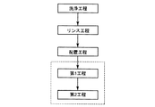
図2に示すように、本実施の形態において、被処理ウエハWは、洗浄室35内において、洗浄処理を施される(洗浄工程)。上述したように、洗浄処理としては、洗浄液を用いた超音波洗浄等が挙げられる。次に、洗浄室35内において、リンス処理を施される(リンス工程)。この工程において、被処理ウエハWは、例えば、純水源36から供給される純水に浸され、洗浄処理で用いられた洗浄液が濯ぎ落とされる。
As shown in FIG. 2, in the present embodiment, the processing target wafer W is subjected to a cleaning process in a cleaning chamber 35 (cleaning step). As described above, examples of the cleaning treatment include ultrasonic cleaning using a cleaning liquid. Next, a rinsing process is performed in the cleaning chamber 35 (rinsing process). In this step, the wafer W to be processed is immersed in, for example, pure water supplied from the
濯ぎ工程が終了すると、洗浄室35と処理室30とを区切る開閉機構34が開き、洗浄室35と処理室30とが連通する。そして、複数のウエハWが処理室30内へと上昇する。複数のウエハWが処理室30内に移動すると、開閉機構34が再び閉じて、洗浄室35と処理室30とが区画される。このようにして処理室30内にウエハWが配置される(配置工程)。
When the rinsing process is completed, the opening /
次に、処理室30内において、収容されたウエハWを乾燥させる乾燥工程が開始される。
Next, in the
ところで、上述の洗浄工程、リンス工程およびウエハ配置工程と並行し、不活性ガス(例えば、窒素)が、不活性ガス源27から加熱装置40内に入口41aを介して供給されている。配管50内を流れる窒素は第1乃至第4スパイラル部51,52,53,54内を通過する際に、第1乃至第4加熱機構56,57,58,59から各スパイラル部51,52,53,54に加えられた熱によって加熱される。
Meanwhile, in parallel with the above-described cleaning process, rinsing process, and wafer placement process, an inert gas (for example, nitrogen) is supplied from the
このとき、制御装置20は、中間温度センサ45による測定値が所定の値となるよう、第1電力調整器56aから第1加熱機構56への電力供給量および第2電力調整器57aから第2加熱機構57への電力供給量を、記録媒体22に記録されたプログラムに従って制御する。つまり、制御装置20は、加熱中の不活性ガスの温度が予め設定された温度となるように、第1加熱機構56の出力および第2加熱機構57の出力を、中間温度センサ45の測定値を入力値としたフィードバック制御を用いて、決定する。同様に、制御装置20は、最終温度センサ46による測定値が所定の値となるよう、第3電力調整器58aから第3加熱機構58への電力供給量および第4電力調整器59aから第4加熱機構59への電力供給量を、記録媒体22に記録されたプログラムに従って制御する。つまり、制御装置20は、加熱後の不活性ガスの温度が予め設定された温度となるように、第3加熱機構58の出力および第4加熱機構59の出力を、最終温度センサ46の測定値を入力値としたフィードバック制御により、決定する。なお、制御装置20による制御方式としては、種々の公知な制御方法を採用することができるが、一般的に有効な方法として、PID制御が挙げられる。
At this time, the
ところでこの間、加熱された不活性ガスの一部は処理室30内に導入され、残りの不活性ガスはドレン48から配管50外に排出される。このようにして乾燥工程が開始される前に、配管50の温度が所望の温度に保たれ、乾燥工程の開始時に、加熱装置40の出口44から所望の温度あるいは所望の温度近傍に加熱された不活性ガスを供給し得る状態となっている。
Meanwhile, a part of the heated inert gas is introduced into the
図2に示すように、本実施の形態において、乾燥工程は第1工程と第2工程とを有している。第1工程においては、加熱装置40にて不活性ガスとIPAとの混合流体が加熱され、加熱された混合流体が吹き出し口31を介して処理室30内に供給される。一方、第2工程においては、加熱装置40にて不活性ガスが加熱され、加熱された不活性ガスが吹き出し口31を介して処理室30内に供給される。以下、第1工程および第2工程について順に説明する。
As shown in FIG. 2, in the present embodiment, the drying step has a first step and a second step. In the first step, the mixed fluid of the inert gas and IPA is heated by the
第1工程において、まず、不活性ガスが不活性ガス源27から加熱装置40に入口41aを介して供給されるとともに、液体のIPAが処理液源28から加熱装置40に入口41bを介して供給される。加熱装置40に供給された不活性ガスとIPAとは合流部42にて合流し、その後、混合流体として配管50内を流れることになる。
In the first step, first, an inert gas is supplied from the
混合流体は、配管50の第1乃至第4スパイラル部51,52,53,54内を通過する際、対応する各加熱機構56,57,58,59からの熱によって加熱される。ここで、表1を用いて、第1工程における各加熱機構56,57,58,59の出力について説明する。

表1に示すように、制御装置20は、第1工程中、記録媒体22に記録されたプログラムに従い、第1電力調整器56aから第1加熱機構56への電力供給量および第2電力調整器57aから第2加熱機構57への電力供給量が一定値となるようにする。つまり、制御装置20は、第1加熱機構56の出力および第2加熱機構57の出力を一定とするよう、第1加熱機構56の出力および第2加熱機構57の出力を制御する。なお、第1加熱機構56の出力および第2加熱機構57の出力は、定格出力や定格出力の所定の割合(例えば70%や80%等)等に設定され得る。一方、制御装置20は、最終温度センサ46による測定値が所定の値となるよう、第3電力調整器58aから第3加熱機構58への電力供給量および第4電力調整器59aから第4加熱機構59への電力供給量を、記録媒体22に記録されたプログラムに従って制御する。つまり、制御装置20は、加熱後の混合流体の温度が予め設定された温度となるように、第3加熱機構58の出力および第4加熱機構59の出力を、フィードバック制御を用いて決定する。したがって、第1工程中、中間温度センサ45は、単なる監視用センサとして機能する。
As shown in Table 1, during the first step, the
乾燥工程の第1工程が開始されると、加熱装置40内に液体のIPAが供給されるようになる。IPAの供給量は、通常で2ml/sec、多くて4ml/sec程度となる。そして、液体のIPAを供給することによって、混合流体の温度は、それまで配管50内を流れていた不活性ガスの温度よりも低くなってしまう。また、配管50の温度も、それまで維持されていた所望の温度よりも低くなってしまう。
When the first step of the drying step is started, liquid IPA is supplied into the
その一方で、上述したように、第1加熱機構56の出力および第2加熱機構57の出力は一定の値をとるように維持される。したがって、第2加熱機構57によって加熱される第2スパイラル部52直後に配置された中間温度センサ45の測定値は、時間の経過に伴って上下を繰り返すようには変動しない。中間温度センサ45の測定値は、好ましくは、第1工程開始時にいったん降下し、その後、上昇を続けるように変動する。また、中間温度センサ45以降の第3スパイラル部53および第4スパイラル部54に加えられる加熱量は、最終温度センサ46の測定値に基づき、制御される。この結果、加熱装置40の出口44を通過する際、混合流体が所望の温度を有するようになり、混合流体中におけるIPAは蒸気化した状態となる。
On the other hand, as described above, the output of the
このようにして、蒸気化したIPAと窒素とを含む混合流体が、吹き出し口31を介して処理室30内に供給されるようになる。そして、処理室30内の雰囲気が、蒸気化したIPAと窒素とを含む混合流体によって置換されるようになる。このようなIPA蒸気を含む雰囲気によって、ウエハWの表面に付着していた純水膜や純水滴をウエハWの表面から迅速に取り除くことができる。このとき、純水膜や純水滴に含有されていたパーティクルは、ウエハWの表面に残存することなく、純水膜や純水滴とともにウエハWの表面から除去されるようになる。このような第1工程は、例えば60秒から120秒間継続され、IPA源28からのIPAの供給が停止することによって終了する。
In this way, the mixed fluid containing vaporized IPA and nitrogen is supplied into the
そして、IPA源28からのIPAの供給が停止することによって、乾燥工程の第2工程が開始される。すなわち、第2工程においては、IPAの供給が停止する一方で、不活性ガスが不活性ガス源27から加熱装置40に入口41aを介して供給され続ける。不活性ガスは、配管50の第1乃至第4スパイラル部51,52,53,54内を通過する際、対応する各加熱機構56,57,58,59から熱によって加熱される。
Then, when the supply of IPA from the
表2に示すように、制御装置20は、第2工程中、中間温度センサ45による測定値が所定の値となるよう、第1電力調整器56aから第1加熱機構56への電力供給量および第2電力調整器57aから第2加熱機構57への電力供給量を、記録媒体22に記録されたプログラムに従って制御する。つまり、制御装置20は、加熱中の不活性ガスの温度が予め設定された温度となるように、第1加熱機構56の出力および第2加熱機構57の出力を、フィードバック制御により決定する。一方、制御装置20は、最終温度センサ46による測定値が所定の値となるよう、第3電力調整器58aから第3加熱機構58への電力供給量および第4電力調整器59aから第4加熱機構59への電力供給量を、記録媒体22に記録されたプログラムに従って制御する。つまり、制御装置20は、加熱後の不活性ガスの温度が予め設定された温度となるように、第3加熱機構58の出力および第4加熱機構59の出力を、フィードバック制御により決定する。
As shown in Table 2, the
この結果、加熱装置40の出口44を通過する際、不活性ガスが所望の温度を有するようになる。所望の温度まで加熱された不活性ガスは、吹き出し口31を介して処理室30内に供給され、これにより、処理室30内からIPA蒸気が排出されるようになる。この結果、処理室30内の雰囲気が不活性ガスによって置換され、ウエハWが完全に乾燥する。このような第2工程は、例えば60秒から240秒間継続される。
As a result, the inert gas has a desired temperature when passing through the
後述する実施例から明らかとなるように、以上のように第1工程中における第1加熱機構56の出力および第2加熱機構57の出力が一定の値をとるようにした場合、乾燥処理後にウエハWに残存するパーティクル数は非常に少なくなる。このような現象が生じるメカニズムは明らかではないが、その一要因と考えられ得るメカニズムについて説明する。ただし、本件発明は以下のメカニズムの限定されるものではない。
As will be apparent from the examples described later, when the output of the
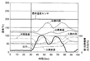
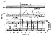
第1加熱機構56の出力および第2加熱機構57の出力をフィードバック制御によって決定するようにした場合、液体IPAの供給開始時から数十秒間、上流側のスパイラル部内における温度が上下変動を繰り返すようになる。ここで図3および図4は、液体IPAの供給時における、第1スパイラル部51の入側外表面温度、入側内部温度、中間外表面温度、出側外表面温度、出側内部温度(各位置は図1参照)、最終温度センサ測定値、並びに、第1加熱機構56の定格出力に対する出力の比を、時間経過とともに示している。図3および図4に示す例において、第1加熱機構56の出力は、第1スパイラル部51の出側外表面温度を所定の温度に維持するよう、PID制御によって決定されている。また、図4に示す例は、図3に示す例に比べてPID制御の入力値(出側外表面温度)に対する感度を高めたものである。
When the output of the
図3および図4に示すように、液体IPAの供給開始時から数十秒間、第1スパイラル部51内における各位置の温度は激しく上下変動を繰り返すようになる。つまり、第1スパイラル部51内を通過する流体の温度は安定していない。その一方で、最終温度センサ46を通過する際の流体温度は、下流側の加熱機構を用いた温度制御により、所望の値に安定するようになっている。
As shown in FIGS. 3 and 4, the temperature at each position in the
ところで、IPAを安定して蒸気化させるためには、混合流体を所定の温度以上に加熱するだけでなく、所定の温度以上に所定の時間維持することが有効であると考えられる。すなわち、IPA供給による温度低下が著しい上流側の加熱機構の出力を、フィードバック制御(より具体的には、PID制御)により求められる変動出力として、流体温度が上下変動を繰り返すようにすることは、IPAを確実に蒸気化させるという点において好ましくないと考えられる。その一方で、加熱機構の出力を固定出力として、流体温度を早期に上昇させ始めるとともに安定して上昇させることは、IPAを確実に蒸気化させるという点において有効であると考えられる。 By the way, in order to stably vaporize IPA, it is considered effective not only to heat the mixed fluid to a predetermined temperature or higher but also to maintain the mixed fluid at a predetermined temperature or higher for a predetermined time. That is, the output of the heating mechanism on the upstream side where the temperature drop due to the IPA supply is remarkable is changed as a fluctuation output obtained by feedback control (more specifically, PID control), so that the fluid temperature repeatedly fluctuates up and down. It is considered undesirable in terms of reliably vaporizing IPA. On the other hand, setting the output of the heating mechanism as a fixed output and starting to increase the fluid temperature early and stably increasing it is considered effective in terms of reliably vaporizing the IPA.
また、IPA供給時に大きな温度変動が生じるのは、時間的にはIPAの供給を開始し始めた時期であり、位置的には最も上流側に配置された第1スパイラル部51内である。したがってこのような観点からすれば、少なくとも最上流側に配置された加熱機構51の出力を、少なくとも加熱装置40にIPAを供給し始めてから所定の時間が経過するまでの間、固定出力に設定しておくことにより、乾燥後のウエハWに残留するパーティクル数を低減することができる、と想定される。
Further, a large temperature fluctuation occurs at the time of supplying IPA at a time when the supply of IPA starts in terms of time, and the position is within the
以上のような本実施の形態によれば、乾燥工程の第1工程の間、つまり加熱装置40にIPAが供給されている間にわたって、制御装置20は、上流側の加熱機構の出力を一定の値に維持するようになっている。したがって、この加熱装置40によって加熱される配管50内を流れる混合流体の温度が安定する。この結果、不活性ガスとIPAとを含む混合ガスをIPAが蒸気化した状態で処理室30内に供給し得ると予想される。このようなことから、処理室30内において、パーティクルの付着を効果的に防止しながら、ウエハの乾燥処理を行うことができる。また、固定出力時における加熱機構の出力を増大させることにより、IPAの供給量が多くなった場合にも対応することができる。また、このようなウエハの処理方法は、既存の設備の制御方法を変更することのみよって採用することができる。
According to the present embodiment as described above, during the first step of the drying process, that is, while IPA is supplied to the
上述した実施の形態に関し、本発明の要旨の範囲内で種々の変更が可能である。以下、変形例の一例について説明する。 Various modifications can be made within the scope of the gist of the present invention with respect to the above-described embodiment. Hereinafter, an example of a modification will be described.
上述した実施の形態における基板処理装置10に、上述した温度センサ等の機器類以外の機器、例えば、配管50内を流れる流体の状態や流量等を監視・制御するための機器類を種々の位置に設けるようにしてもよい。
In the
また、上述した実施の形態において、第2工程中、第1加熱機構56の出力および第2加熱機構57の出力が、中間温度センサ45による測定値に基づいたフィードバック制御によって、決定される例を示したが、これに限られない。加熱中または加熱後の流体の温度を予め設定された値にすることを目的として、種々の入力値に基づいたフィードバック制御により、第1加熱機構56の出力および第2加熱機構57の出力が決定されるようにしてもよい。ここで、種々の入力値とは、例えば、第1スパイラル部51や第2スパイラル部52のいずれかの位置における表面温度等が挙げられる。
In the above-described embodiment, an example in which the output of the
同様に、上述した実施の形態において、第1工程中および第2工程中、第3加熱機構58の出力および第4加熱機構59の出力が、最終温度センサ46による測定値に基づいたフィードバック制御によって、決定される例を示したが、これに限られない。加熱中または加熱後の流体の温度を予め設定された値にすることを目的として、種々の入力値に基づいたフィードバック制御により、第3加熱機構58の出力および第4加熱機構59の出力が決定されるようにしてもよい。ここで、種々の入力値とは、例えば、第3スパイラル部53や第4スパイラル部54のいずれかの位置における表面温度等が挙げられる。
Similarly, in the above-described embodiment, during the first step and the second step, the output of the
さらに、上述した実施の形態において、四つの加熱機構56,57,58,59を設けるとともに、これらに対応した四つのスパイラル部51,52,53,54を設けた例を示したが、これに限られない。一つの加熱機構および一つのスパイラル部だけを設けるようにしてもよいし、二つの加熱機構および二つのスパイラル部を設けるようにしてもよいし、三つの加熱機構および三つのスパイラル部を設けるようにしてもよいし、五つ以上の加熱機構および五つ以上のスパイラル部を設けるようにしてもよい。
Further, in the above-described embodiment, an example in which four
さらに、上述した実施の形態において、第1工程の間にわたって、第1加熱機構56の出力および第2加熱機構57の出力が一定の値となるようにした例を示したが、これに限られない。上述したように、少なくとも最上流側に配置された加熱機構51の出力を、少なくとも加熱装置40にIPAが供給され始めてから所定の時間が経過するまでの間、固定出力に設定しておくことにより、乾燥後のウエハWに残留するパーティクル数を低減することができる、と想定される。したがって、表2に示すように、加熱装置40にIPAを供給し始めてから所定の時間が経過するまでの間(表2における「初期」)だけ、すなわち第1工程中の一期間のみ、第1加熱機構56の出力および第2加熱機構57の出力を固定出力とするようにしてもよい。
さらに、表3に示すように、加熱装置40にIPAを供給し始めてから所定の時間が経過するまでの間(表2における「初期」)だけ、第1加熱機構56の出力および第2加熱機構57の出力をある一定の値(例えば、定格出力の80%)に維持し、その後の期間、第1加熱機構56の出力および第2加熱機構57の出力を前記一定の値とは異なる別の一定の値(例えば、定格出力の50%)に維持するようにしてもよい。また、表3に示すように、第1工程を三つ以上の期間に区分けし、各期間において、加熱機構の出力を異なる方法で制御するようにしてもよい。さらに、表3に示すように、第1加熱機構56の出力値(例えば、定格値の80%)と、第2加熱機構57の出力値(例えば、定格値の60%)とを異なる値に設定してもよい。
さらに、加熱装置40にIPAを供給し始めてから所定の時間、最上流側の加熱機構の出力のみを固定出力とし、他の加熱機構の出力をPID制御によって決定される変動出力としてもよい。さらに、加熱装置40にIPAを供給し始めてから所定の時間、最下流側の加熱機構以外の加熱機構の出力を固定出力とし、最下流側の加熱機構の出力のみをPID制御によって決定される変動出力としてもよい。
Furthermore, only the output of the heating mechanism on the most upstream side may be a fixed output for a predetermined time after starting to supply IPA to the
さらに、上述した実施の形態についてのいくつかの変形例を説明してきたが、当然に、複数の変形例を適宜組み合わせて適用することも可能である。 Furthermore, although some modified examples of the above-described embodiment have been described, naturally, a plurality of modified examples can be applied in combination as appropriate.
ところで、上述のように、基板処理装置10はコンピュータ21を含む制御装置20を備えている。この制御装置20により、基板処理装置10の各構成要素が動作させられ、被処理ウエハWに対する処理が実行されるようになっている。そして、基板処理装置10を用いたウエハWの処理を実施するために、制御装置20のコンピュータ21によって実行されるプログラムも本件の対象である。また、当該プログラムを記録したコンピュータ読み取り可能な記録媒体22も、本件の対象である。ここで、記録媒体22とは、フロッピーディスク(フレキシブルディスク)やハードディスクドライブ等の単体として認識することができるものの他、各種信号を伝搬させるネットワークも含む。
Incidentally, as described above, the
なお、以上の説明においては、本発明による基板処理方法、基板処理装置、プログラム、および記録媒体を、ウエハWの処理に適用した例を示しているが、これに限られず、LCD基板やCD基板等の処理に適用することも可能である。 In the above description, the substrate processing method, the substrate processing apparatus, the program, and the recording medium according to the present invention are applied to the processing of the wafer W. However, the present invention is not limited to this, and an LCD substrate or a CD substrate is used. It is also possible to apply to such processing.
本発明を実施例によってさらに詳細に説明する。 The invention is explained in more detail by means of examples.
図1に示す基板処理装置を用い、リンス処理後のウエハに対し、IPAと窒素とを含む混合流体を加熱して処理室に供給する第1工程と、窒素を加熱して処理室に供給する第2工程と、を有する乾燥処理を施した。第1乃至第4加熱機構の定格出力はそれぞれ2000Wであった。第1工程中における窒素の供給量を100l/minとし、第2工程中における窒素の供給量を100l/minとした。第2工程の総時間を150秒とした。 Using the substrate processing apparatus shown in FIG. 1, a first step of heating a mixed fluid containing IPA and nitrogen to the wafer after rinsing and supplying it to the processing chamber, and heating and supplying nitrogen to the processing chamber And a second process. The rated outputs of the first to fourth heating mechanisms were 2000 W, respectively. The supply amount of nitrogen in the first step was 100 l / min, and the supply amount of nitrogen in the second step was 100 l / min. The total time for the second step was 150 seconds.
第1工程および第2工程の間、第3加熱機構の出力および第4加熱機構の出力は、最終温度センサの測定値が所定の値となるように、最終温度センサの測定値に基づいたフィードバック制御により、決定した。また、第2工程の間、第1加熱機構の出力および第2加熱機構の出力は、中間温度センサの測定値が所定の値となるように、中間温度センサの測定値に基づいたフィードバック制御により、決定した。なお、フィードバック制御の制御方式として、PID制御を用いた。 During the first step and the second step, the output of the third heating mechanism and the output of the fourth heating mechanism are feedback based on the measured value of the final temperature sensor so that the measured value of the final temperature sensor becomes a predetermined value. Determined by control. During the second step, the output of the first heating mechanism and the output of the second heating mechanism are controlled by feedback control based on the measured value of the intermediate temperature sensor so that the measured value of the intermediate temperature sensor becomes a predetermined value. ,Were determined. Note that PID control was used as a control method for feedback control.
以下、各実施例および各比較例について個別に設定した条件について、図5を参照しながら説明する。ここで図5は、各実施例における第1工程中の第1加熱機構および第2加熱機構の制御方法を説明するための図である。 Hereinafter, conditions individually set for each example and each comparative example will be described with reference to FIG. Here, FIG. 5 is a diagram for explaining a control method of the first heating mechanism and the second heating mechanism during the first step in each embodiment.
(実施例1A)
図5に示すように、実施例1Aでは、第1工程の総時間を90秒とした。第1工程の間に渡って、第1加熱機構の出力および第2加熱機構の出力を一定の値に設定した。第1加熱機構の出力値および第2加熱機構の出力値は、表4に示すように、定格出力の60%、70%、80%、90%および100%の五種類に設定した(それぞれ実施例1A−1乃至実施例1A−5とする)。
また、IPA液体の供給量を4ml/secとした。
Example 1A
As shown in FIG. 5, in Example 1A, the total time of the first step was 90 seconds. Over the first step, the output of the first heating mechanism and the output of the second heating mechanism were set to constant values. As shown in Table 4, the output value of the first heating mechanism and the output value of the second heating mechanism were set to five types of 60%, 70%, 80%, 90% and 100% of the rated output (respectively implemented) Example 1A-1 to Example 1A-5).
The supply amount of the IPA liquid was 4 ml / sec.
(実施例1B)
図5に示すように、実施例1Bでは、第1工程の総時間を90秒とした。第1工程の間に渡って、第1加熱機構の出力および第2加熱機構の出力を一定の値に設定した。第1加熱機構の出力値および第2加熱機構の出力値は、定格出力の70%に設定した。
また、IPA液体の供給量を3ml/secとした。
(Example 1B)
As shown in FIG. 5, in Example 1B, the total time of the first step was 90 seconds. Over the first step, the output of the first heating mechanism and the output of the second heating mechanism were set to constant values. The output value of the first heating mechanism and the output value of the second heating mechanism were set to 70% of the rated output.
The supply amount of the IPA liquid was 3 ml / sec.
(実施例1C)
図5に示すように、実施例1Cでは、第1工程の総時間を90秒とした。第1工程の間に渡って、第1加熱機構の出力および第2加熱機構の出力を一定の値に設定した。第1加熱機構の出力値および第2加熱機構の出力値は、定格出力の60%に設定した。
また、IPA液体の供給量を2ml/secとした。
(Example 1C)
As shown in FIG. 5, in Example 1C, the total time for the first step was 90 seconds. Over the first step, the output of the first heating mechanism and the output of the second heating mechanism were set to constant values. The output value of the first heating mechanism and the output value of the second heating mechanism were set to 60% of the rated output.
The supply amount of the IPA liquid was 2 ml / sec.
(実施例2A)
図5に示すように、実施例2Aでは、第1工程の総時間を60秒とした。第1工程の間に渡って、第1加熱機構の出力および第2加熱機構の出力を一定の値に設定した。第1加熱機構の出力値および第2加熱機構の出力値は、定格出力の80%に設定した。
また、IPA液体の供給量を4ml/secとした。
(Example 2A)
As shown in FIG. 5, in Example 2A, the total time of the first step was 60 seconds. Over the first step, the output of the first heating mechanism and the output of the second heating mechanism were set to constant values. The output value of the first heating mechanism and the output value of the second heating mechanism were set to 80% of the rated output.
The supply amount of the IPA liquid was 4 ml / sec.
(実施例2B)
図5に示すように、実施例2Bでは、第1工程の総時間を60秒とした。第1工程の間に渡って、第1加熱機構の出力および第2加熱機構の出力を一定の値に設定した。第1加熱機構の出力値および第2加熱機構の出力値は、定格出力の70%に設定した。
また、IPA液体の供給量を3ml/secとした。
(Example 2B)
As shown in FIG. 5, in Example 2B, the total time of the first step was 60 seconds. Over the first step, the output of the first heating mechanism and the output of the second heating mechanism were set to constant values. The output value of the first heating mechanism and the output value of the second heating mechanism were set to 70% of the rated output.
The supply amount of the IPA liquid was 3 ml / sec.
(実施例2C)
図5に示すように、実施例2Cでは、第1工程の総時間を60秒とした。第1工程の間に渡って、第1加熱機構の出力および第2加熱機構の出力を一定の値に設定した。第1加熱機構の出力値および第2加熱機構の出力値は、定格出力の60%に設定した。
また、IPA液体の供給量を2ml/secとした。
(Example 2C)
As shown in FIG. 5, in Example 2C, the total time of the first step was 60 seconds. Over the first step, the output of the first heating mechanism and the output of the second heating mechanism were set to constant values. The output value of the first heating mechanism and the output value of the second heating mechanism were set to 60% of the rated output.
The supply amount of the IPA liquid was 2 ml / sec.
(実施例3A)
図5に示すように、実施例3Aでは、第1工程の総時間を120秒とした。第1工程の間に渡って、第1加熱機構の出力および第2加熱機構の出力を一定の値に設定した。第1加熱機構の出力値および第2加熱機構の出力値は、定格出力の80%に設定した。
また、IPA液体の供給量を4ml/secとした。
(Example 3A)
As shown in FIG. 5, in Example 3A, the total time of the first step was 120 seconds. Over the first step, the output of the first heating mechanism and the output of the second heating mechanism were set to constant values. The output value of the first heating mechanism and the output value of the second heating mechanism were set to 80% of the rated output.
The supply amount of the IPA liquid was 4 ml / sec.
(実施例3B)
図5に示すように、実施例3Bでは、第1工程の総時間を120秒とした。第1工程の間に渡って、第1加熱機構の出力および第2加熱機構の出力を一定の値に設定した。第1加熱機構の出力値および第2加熱機構の出力値は、定格出力の70%に設定した。
また、IPA液体の供給量を3ml/secとした。
(Example 3B)
As shown in FIG. 5, in Example 3B, the total time of the first step was 120 seconds. Over the first step, the output of the first heating mechanism and the output of the second heating mechanism were set to constant values. The output value of the first heating mechanism and the output value of the second heating mechanism were set to 70% of the rated output.
The supply amount of the IPA liquid was 3 ml / sec.
(実施例3C)
図5に示すように、実施例3Cでは、第1工程の総時間を120秒とした。第1工程の間に渡って、第1加熱機構の出力および第2加熱機構の出力を一定の値に設定した。第1加熱機構の出力値および第2加熱機構の出力値は、定格出力の60%に設定した。
また、IPA液体の供給量を2ml/secとした。
(Example 3C)
As shown in FIG. 5, in Example 3C, the total time of the first step was 120 seconds. Over the first step, the output of the first heating mechanism and the output of the second heating mechanism were set to constant values. The output value of the first heating mechanism and the output value of the second heating mechanism were set to 60% of the rated output.
The supply amount of the IPA liquid was 2 ml / sec.
(実施例4A)
図5に示すように、実施例4では、第1工程の総時間を90秒とした。第1工程開始時からの30秒間、第1加熱機構の出力および第2加熱機構の出力を一定の値に設定した。第1加熱機構の出力値および第2加熱機構の出力値は、表4に示すように、定格出力の60%および100%の二種類に設定した(それぞれ実施例4A−1および実施例4A−2とする)。
一方、第1工程の残り60秒間、第1加熱機構の出力および第2加熱機構の出力は、中間温度センサの測定値が所定の値となるように、中間温度センサの測定値に基づいたフィードバック制御により、決定した。なお、フィードバック制御の制御方式として、PID制御を用いた。
また、IPA液体の供給量を4ml/secとした。
(Example 4A)
As shown in FIG. 5, in Example 4, the total time of the first step was 90 seconds. The output of the first heating mechanism and the output of the second heating mechanism were set to constant values for 30 seconds from the start of the first step. As shown in Table 4, the output value of the first heating mechanism and the output value of the second heating mechanism were set to two types of 60% and 100% of the rated output (Example 4A-1 and Example 4A-, respectively). 2).
On the other hand, for the remaining 60 seconds of the first step, the output of the first heating mechanism and the output of the second heating mechanism are feedback based on the measured value of the intermediate temperature sensor so that the measured value of the intermediate temperature sensor becomes a predetermined value. Determined by control. Note that PID control was used as a control method for feedback control.
The supply amount of the IPA liquid was 4 ml / sec.
(比較例1A、1B、1C)
比較例1では、第1工程の総時間を90秒とした。第1工程の間に渡って、第1加熱機構の出力および第2加熱機構の出力は、中間温度センサの測定値が所定の値となるように、中間温度センサの測定値に基づいたフィードバック制御により、決定した。なお、フィードバック制御の制御方式として、PID制御を用いた。
また、IPA液体の供給量を4ml/sec、3ml/secおよび2ml/secとした(それぞれ比較例1A、比較例1Bおよび比較例1Cとする)。
(Comparative Examples 1A, 1B, 1C)
In Comparative Example 1, the total time for the first step was 90 seconds. During the first step, the output of the first heating mechanism and the output of the second heating mechanism are feedback control based on the measured value of the intermediate temperature sensor so that the measured value of the intermediate temperature sensor becomes a predetermined value. Determined. Note that PID control was used as a control method for feedback control.
The supply amount of the IPA liquid was 4 ml / sec, 3 ml / sec, and 2 ml / sec (referred to as Comparative Example 1A, Comparative Example 1B, and Comparative Example 1C, respectively).
(比較例2A、2B、2C)
比較例2では、第1工程の総時間を60秒とした。第1工程の間に渡って、第1加熱機構の出力および第2加熱機構の出力は、中間温度センサの測定値が所定の値となるように、中間温度センサの測定値に基づいたフィードバック制御により、決定した。なお、フィードバック制御の制御方式として、PID制御を用いた。
また、IPA液体の供給量を4ml/sec、3ml/secおよび2ml/secとした(それぞれ比較例2A、比較例2Bおよび比較例2Cとする)。
(Comparative Examples 2A, 2B, 2C)
In Comparative Example 2, the total time for the first step was 60 seconds. During the first step, the output of the first heating mechanism and the output of the second heating mechanism are feedback control based on the measured value of the intermediate temperature sensor so that the measured value of the intermediate temperature sensor becomes a predetermined value. Determined. Note that PID control was used as a control method for feedback control.
The supply amount of the IPA liquid was 4 ml / sec, 3 ml / sec, and 2 ml / sec (referred to as Comparative Example 2A, Comparative Example 2B, and Comparative Example 2C, respectively).
(比較例3A、3B、3C)
比較例3では、第1工程の総時間を120秒とした。第1工程の間に渡って、第1加熱機構の出力および第2加熱機構の出力は、中間温度センサの測定値が所定の値となるように、中間温度センサの測定値に基づいたフィードバック制御により、決定した。なお、フィードバック制御の制御方式として、PID制御を用いた。
また、IPA液体の供給量を4ml/sec、3ml/secおよび2ml/secとした(それぞれ比較例3A、比較例3Bおよび比較例3Cとする)。
(Comparative Examples 3A, 3B, 3C)
In Comparative Example 3, the total time for the first step was 120 seconds. During the first step, the output of the first heating mechanism and the output of the second heating mechanism are feedback control based on the measured value of the intermediate temperature sensor so that the measured value of the intermediate temperature sensor becomes a predetermined value. Determined. Note that PID control was used as a control method for feedback control.
The supply amount of the IPA liquid was 4 ml / sec, 3 ml / sec, and 2 ml / sec (referred to as Comparative Example 3A, Comparative Example 3B, and Comparative Example 3C, respectively).
(パーティクル数の計測)
上述の各実施例および各比較例について、パーティクルカウンタを用い、ウエハ一枚に残存するパーティクルの平均数を測定した。
(Measurement of the number of particles)
For each of the above examples and comparative examples, the average number of particles remaining on one wafer was measured using a particle counter.
表4に、実施例1A−1乃至1A−5、実施例4A−1および4A−2、並びに、比較例1Aの測定結果を示す。表4中には、パーティクルカウンタによって、0.06μm以上のパーティクル数を測定した場合の測定結果、0.09μm以上のパーティクル数を測定した場合の測定結果、および、0.16μm以上のパーティクル数を測定した場合の測定結果を示している。表4から明らかなように、実施例1A−1乃至1A−5、並びに、実施例4A−1および4A−2においては、比較例1Aに比べ、ウエハ一枚に残存する平均パーティクル数を格段に低減することができる。
また、図6および図7には、比較例1Aおよび実施例1A−3における、最終温度センサの測定値、中間温度センサの測定値、および第1スパイラル部の出側外表面(図1参照)の温度測定値を、時間の経過とともに示している。実施例だけでなく比較例においても、最終温度センサの測定値はほぼ一定値に安定していた。 6 and 7 show the measured value of the final temperature sensor, the measured value of the intermediate temperature sensor, and the outer surface of the first spiral portion in Comparative Example 1A and Example 1A-3 (see FIG. 1). The temperature measurement values of are shown over time. In the comparative example as well as the example, the measured value of the final temperature sensor was stable at a substantially constant value.
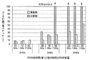
一方、図8および図9には、各実施例のパーティクル測定結果(白抜き)を、対応する比較例(斜線)とともにグラフで表している。なお、図8はパーティクルカウンタによって0.16μm以上のパーティクル数を測定した場合の測定結果を示し、図9は0.06μm以上のパーティクル数を測定した場合の測定結果を示している。IPAの供給量が3ml/secおよび4ml/secの場合、実施例においても、比較例に比べ、第1工程の時間に関係無くウエハ一枚に残存する平均パーティクル数を格段に低減することができる。 On the other hand, in FIG. 8 and FIG. 9, the particle measurement results (outlined) of each example are shown in a graph together with the corresponding comparative example (shaded line). 8 shows a measurement result when the number of particles of 0.16 μm or more is measured by the particle counter, and FIG. 9 shows a measurement result when the number of particles of 0.06 μm or more is measured. When the supply amount of IPA is 3 ml / sec and 4 ml / sec, the average number of particles remaining on one wafer can be remarkably reduced in the embodiment as compared with the comparative example regardless of the time of the first step. .
10 基板処理装置
20 制御装置
21 コンピュータ
22 記録媒体
30 処理室
31 吹き出し口
40 加熱装置
41a 入口
41b 入口
44 出口
45 中間温度センサ
46 最終温度センサ
50 配管(流路)
51 第1スパイラル部
52 第2スパイラル部
53 第3スパイラル部
54 第4スパイラル部
56 第1加熱機構
57 第2加熱機構
58 第3加熱機構
59 第4加熱機構
DESCRIPTION OF
51
Claims (12)
処理室内に被処理基板を配置する工程と、
前記入口から前記加熱装置内に不活性ガスと処理液とを供給して、前記不活性ガスと前記処理液とを含む混合流体を前記加熱装置内において加熱するとともに、前記加熱装置の前記出口から排出される加熱された前記混合流体を、被処理基板が配置された処理室内へ供給する工程と、を備え、
前記混合流体を処理室に供給する工程において、前記加熱装置の最も入口側に配置された加熱機構の出力は、前記加熱装置に前記処理液が供給され始めてから所定の時間が経つまでの間、予め設定された一定の値を維持し、最も出口側に配置された加熱機構の出力は、加熱中または加熱後の混合流体の温度を予め設定された値とすることを目的として、フィードバック制御により決定される
ことを特徴とする基板処理方法。 A substrate processing method for drying a substrate to be processed using a fluid heated by a heating device having an inlet, an outlet, and a plurality of heating mechanisms for heating a fluid flowing from the inlet to the outlet,
Arranging the substrate to be processed in the processing chamber;
An inert gas and a treatment liquid are supplied from the inlet into the heating device, and the mixed fluid containing the inert gas and the treatment liquid is heated in the heating device, and from the outlet of the heating device. Supplying the heated mixed fluid to be discharged into a processing chamber in which a substrate to be processed is arranged, and
In the step of supplying the mixed fluid to the processing chamber, the output of the heating mechanism arranged on the most inlet side of the heating device is until a predetermined time passes after the processing liquid starts to be supplied to the heating device. Maintaining a preset constant value, the output of the heating mechanism arranged on the most outlet side uses feedback control for the purpose of setting the temperature of the mixed fluid during or after heating to a preset value. A substrate processing method characterized by being determined.
ことを特徴とする請求項1に記載の基板処理方法。 In the step of supplying the mixed fluid to the processing chamber, the output of the heating mechanism arranged closest to the inlet side is at least one period after the predetermined time has elapsed since the processing liquid started to be supplied to the heating device. 2. The substrate processing method according to claim 1, wherein a second constant value lower than the constant value is maintained.
ことを特徴とする請求項1または2に記載の基板処理方法。 In the step of supplying the mixed fluid to the processing chamber, the temperature of the mixed fluid during or after heating is preset after the output of the heating mechanism arranged at the most inlet side is maintained at a constant value. 3. The substrate processing method according to claim 1, wherein the substrate processing method is determined by feedback control for the purpose of obtaining a value.
ことを特徴とする請求項1に記載の基板処理方法。 In the step of supplying the mixed fluid to the processing chamber, the output of the heating mechanism arranged closest to the inlet side is maintained at a constant value while the processing liquid is supplied to the heating device. The substrate processing method according to claim 1, wherein:
前記加熱された不活性ガスを前記処理室内へ供給する工程において、前記加熱装置の加熱機構の出力は、加熱中または加熱後の不活性ガスの温度を予め設定された値にすることを目的として、フィードバック制御により決定される
ことを特徴とする請求項1〜4のいずれか一項に記載の基板処理方法。 The step is performed after the step of supplying the mixed fluid to the processing chamber, and the inert gas is supplied into the heating device from the inlet to heat the inert gas in the heating device. Supplying the heated inert gas discharged from the outlet of the heating apparatus into the processing chamber,
In the step of supplying the heated inert gas into the processing chamber, the output of the heating mechanism of the heating device is for the purpose of setting the temperature of the inert gas during or after heating to a preset value. The substrate processing method according to claim 1, wherein the substrate processing method is determined by feedback control.
前記加熱装置の前記出口と連結され、前記加熱装置から加熱された流体を供給されることによって、内部に収容した被処理基板を乾燥させるようになされた処理室と、
前記複数の加熱機構の出力を制御する制御装置と、を備え、
前記制御装置は、
前記加熱装置によって加熱された不活性ガスと処理液とを含む混合流体を前記処理室に供給する工程を備えた被処理基板の乾燥処理を行う際に、
前記加熱装置の最も入口側に配置された加熱機構の出力を、前記加熱装置に前記処理液が供給され始めてから所定の時間が経つまでの間、予め設定された一定の値に維持し、
最も出口側に配置された加熱機構の出力を、加熱中または加熱後の混合流体の温度を予め設定された値とすることを目的として、フィードバック制御により決定する
ことを特徴とする基板処理装置。 A heating device having an inlet, an outlet, a channel extending from the inlet to the outlet, and a plurality of heating mechanisms for heating the channel;
A processing chamber connected to the outlet of the heating device and supplied with a heated fluid from the heating device, thereby drying a substrate to be processed housed therein;
A control device for controlling the outputs of the plurality of heating mechanisms,
The controller is
When performing a drying process on a substrate to be processed, which includes a step of supplying a mixed fluid containing an inert gas heated by the heating device and a processing liquid to the processing chamber.
The output of the heating mechanism arranged on the most inlet side of the heating device is maintained at a preset constant value until a predetermined time elapses after the treatment liquid starts to be supplied to the heating device,
A substrate processing apparatus, wherein an output of a heating mechanism arranged on the most outlet side is determined by feedback control for the purpose of setting a temperature of a mixed fluid during or after heating to a preset value.
前記加熱装置によって加熱された不活性ガスと処理液とを含む混合流体を前記処理室に供給する工程を備えた被処理基板の乾燥処理を行う際に、
前記加熱装置の最も入口側に配置された加熱機構の出力を、前記加熱装置に前記処理液が供給され始めてから前記所定の時間が経過した後の少なくとも一期間、前記一定の値よりも低い第2の一定に値に維持する、
ことを特徴とする請求項6に記載の基板処理装置。 The controller is
When performing a drying process on a substrate to be processed, which includes a step of supplying a mixed fluid containing an inert gas heated by the heating device and a processing liquid to the processing chamber.
The output of the heating mechanism arranged on the most inlet side of the heating device is lower than the predetermined value for at least one period after the predetermined time has elapsed since the processing liquid began to be supplied to the heating device. Maintain a constant value of 2,
The substrate processing apparatus according to claim 6.
前記加熱装置によって加熱された不活性ガスと処理液とを含む混合流体を前記処理室に供給する工程を備えた被処理基板の乾燥処理を行う際に、
前記加熱装置の最も入口側に配置された加熱機構の出力を、一定の値に維持した後に、
加熱中または加熱後の混合流体の温度を予め設定された値とすることを目的として、フィードバック制御により決定する、
ことを特徴とする請求項6または7に記載の基板処理装置。 The controller is
When performing a drying process on a substrate to be processed, which includes a step of supplying a mixed fluid containing an inert gas heated by the heating device and a processing liquid to the processing chamber.
After maintaining the output of the heating mechanism arranged on the most inlet side of the heating device at a constant value,
For the purpose of setting the temperature of the mixed fluid during or after heating to a preset value, it is determined by feedback control.
The substrate processing apparatus according to claim 6 or 7, wherein
ことを特徴とする請求項6に記載の基板処理装置。 The said control apparatus maintains the output of the heating mechanism arrange | positioned at the most inlet side to a fixed value over the period when the said process liquid is supplied to the said heating apparatus. Substrate processing equipment.
前記加熱装置によって加熱された不活性ガスと処理液とを含む混合流体を前記処理室に供給する工程の後に、前記加熱装置によって加熱された不活性ガスを前記処理室に供給する工程が、被処理基板の乾燥処理として、行われる際に、
前記加熱装置の加熱機構の出力を、加熱中または加熱後の不活性ガスの温度を予め設定された値にすることを目的として、フィードバック制御により決定する
ことを特徴とする請求項6〜9のいずれか一項に記載の基板処理装置。 The controller is
A step of supplying an inert gas heated by the heating device to the processing chamber after a step of supplying a mixed fluid containing an inert gas heated by the heating device and a processing liquid to the processing chamber; When it is performed as a drying process of the processing substrate,
The output of the heating mechanism of the heating device is determined by feedback control for the purpose of setting the temperature of the inert gas during or after heating to a preset value. The substrate processing apparatus as described in any one of Claims.
前記制御装置によって実行されることにより、請求項1〜5のいずれか一項に記載された被処理基板の処理方法を基板処理装置に実施させることを特徴とするプログラム。 A program executed by a control device that controls a substrate processing apparatus including a heating device having an inlet, an outlet, and a plurality of heating mechanisms that heat a fluid flowing from the inlet to the outlet,
A program for causing a substrate processing apparatus to execute the processing method of a substrate to be processed according to any one of claims 1 to 5, when executed by the control device.
前記プログラムが前記制御装置によって実行されることにより、請求項1〜5のいずれか一項に記載された被処理基板の処理方法を基板洗浄装置に実施させることを特徴とする記録媒体。 A recording medium on which a program executed by a control device that controls a substrate processing apparatus including a heating device having an inlet, an outlet, and a plurality of heating mechanisms that heat a fluid flowing from the inlet to the outlet is recorded Because
A recording medium that causes a substrate cleaning apparatus to perform the processing method of a substrate to be processed according to claim 1, when the program is executed by the control device.
Priority Applications (6)
| Application Number | Priority Date | Filing Date | Title |
|---|---|---|---|
| JP2006243276A JP4762835B2 (en) | 2006-09-07 | 2006-09-07 | Substrate processing method, substrate processing apparatus, program, and program recording medium |
| KR1020070086176A KR101061951B1 (en) | 2006-09-07 | 2007-08-27 | Substrate processing method, substrate processing apparatus and program recording medium |
| TW096133248A TW200816301A (en) | 2006-09-07 | 2007-09-06 | Substrate processing method, substrate processing apparatus, and program storage medium |
| US11/896,936 US8020315B2 (en) | 2006-09-07 | 2007-09-06 | Substrate processing method, substrate processing apparatus, and program storage medium |
| EP07017587A EP1898446A3 (en) | 2006-09-07 | 2007-09-07 | Substrate processing method, substrate processing apparatus, and program storage medium |
| US13/209,741 US8266820B2 (en) | 2006-09-07 | 2011-08-15 | Substrate processing method, and program storage medium therefor |
Applications Claiming Priority (1)
| Application Number | Priority Date | Filing Date | Title |
|---|---|---|---|
| JP2006243276A JP4762835B2 (en) | 2006-09-07 | 2006-09-07 | Substrate processing method, substrate processing apparatus, program, and program recording medium |
Publications (2)
| Publication Number | Publication Date |
|---|---|
| JP2008066535A JP2008066535A (en) | 2008-03-21 |
| JP4762835B2 true JP4762835B2 (en) | 2011-08-31 |
Family
ID=38657151
Family Applications (1)
| Application Number | Title | Priority Date | Filing Date |
|---|---|---|---|
| JP2006243276A Active JP4762835B2 (en) | 2006-09-07 | 2006-09-07 | Substrate processing method, substrate processing apparatus, program, and program recording medium |
Country Status (5)
| Country | Link |
|---|---|
| US (2) | US8020315B2 (en) |
| EP (1) | EP1898446A3 (en) |
| JP (1) | JP4762835B2 (en) |
| KR (1) | KR101061951B1 (en) |
| TW (1) | TW200816301A (en) |
Cited By (2)
| Publication number | Priority date | Publication date | Assignee | Title |
|---|---|---|---|---|
| KR20160027800A (en) * | 2014-09-02 | 2016-03-10 | 주식회사 제우스 | Liquid processing method for substrate and liquid processing apparatus |
| KR101880232B1 (en) * | 2015-07-13 | 2018-07-19 | 주식회사 제우스 | Substrate liquid processing apparatus and substrate liquid processing method |
Families Citing this family (338)
| Publication number | Priority date | Publication date | Assignee | Title |
|---|---|---|---|---|
| US7637029B2 (en) | 2005-07-08 | 2009-12-29 | Tokyo Electron Limited | Vapor drying method, apparatus and recording medium for use in the method |
| US20070298110A1 (en) * | 2006-06-22 | 2007-12-27 | Xerox Corporation | Methods for embedding nanoparticles |
| JP4762835B2 (en) | 2006-09-07 | 2011-08-31 | 東京エレクトロン株式会社 | Substrate processing method, substrate processing apparatus, program, and program recording medium |
| US10378106B2 (en) | 2008-11-14 | 2019-08-13 | Asm Ip Holding B.V. | Method of forming insulation film by modified PEALD |
| US9394608B2 (en) | 2009-04-06 | 2016-07-19 | Asm America, Inc. | Semiconductor processing reactor and components thereof |
| US8802201B2 (en) | 2009-08-14 | 2014-08-12 | Asm America, Inc. | Systems and methods for thin-film deposition of metal oxides using excited nitrogen-oxygen species |
| US9312155B2 (en) | 2011-06-06 | 2016-04-12 | Asm Japan K.K. | High-throughput semiconductor-processing apparatus equipped with multiple dual-chamber modules |
| US9793148B2 (en) | 2011-06-22 | 2017-10-17 | Asm Japan K.K. | Method for positioning wafers in multiple wafer transport |
| US10364496B2 (en) | 2011-06-27 | 2019-07-30 | Asm Ip Holding B.V. | Dual section module having shared and unshared mass flow controllers |
| US10854498B2 (en) | 2011-07-15 | 2020-12-01 | Asm Ip Holding B.V. | Wafer-supporting device and method for producing same |
| US20130023129A1 (en) | 2011-07-20 | 2013-01-24 | Asm America, Inc. | Pressure transmitter for a semiconductor processing environment |
| JP5646419B2 (en) * | 2011-09-09 | 2014-12-24 | 東京エレクトロン株式会社 | Substrate processing apparatus, substrate processing method, and storage medium |
| US9017481B1 (en) | 2011-10-28 | 2015-04-28 | Asm America, Inc. | Process feed management for semiconductor substrate processing |
| US8946830B2 (en) | 2012-04-04 | 2015-02-03 | Asm Ip Holdings B.V. | Metal oxide protective layer for a semiconductor device |
| JP6034231B2 (en) * | 2012-07-25 | 2016-11-30 | 株式会社Kelk | Temperature control device for semiconductor manufacturing apparatus, PID constant calculation method in semiconductor manufacturing, and operation method of temperature control device for semiconductor manufacturing device |
| US9558931B2 (en) | 2012-07-27 | 2017-01-31 | Asm Ip Holding B.V. | System and method for gas-phase sulfur passivation of a semiconductor surface |
| US9659799B2 (en) | 2012-08-28 | 2017-05-23 | Asm Ip Holding B.V. | Systems and methods for dynamic semiconductor process scheduling |
| US9021985B2 (en) | 2012-09-12 | 2015-05-05 | Asm Ip Holdings B.V. | Process gas management for an inductively-coupled plasma deposition reactor |
| US10714315B2 (en) | 2012-10-12 | 2020-07-14 | Asm Ip Holdings B.V. | Semiconductor reaction chamber showerhead |
| US9640416B2 (en) | 2012-12-26 | 2017-05-02 | Asm Ip Holding B.V. | Single-and dual-chamber module-attachable wafer-handling chamber |
| US20160376700A1 (en) | 2013-02-01 | 2016-12-29 | Asm Ip Holding B.V. | System for treatment of deposition reactor |
| US9484191B2 (en) | 2013-03-08 | 2016-11-01 | Asm Ip Holding B.V. | Pulsed remote plasma method and system |
| US9589770B2 (en) | 2013-03-08 | 2017-03-07 | Asm Ip Holding B.V. | Method and systems for in-situ formation of intermediate reactive species |
| JP6224359B2 (en) * | 2013-06-20 | 2017-11-01 | 株式会社Screenホールディングス | Schedule creation method and schedule creation program for substrate processing apparatus |
| US8993054B2 (en) | 2013-07-12 | 2015-03-31 | Asm Ip Holding B.V. | Method and system to reduce outgassing in a reaction chamber |
| US9018111B2 (en) | 2013-07-22 | 2015-04-28 | Asm Ip Holding B.V. | Semiconductor reaction chamber with plasma capabilities |
| US9793115B2 (en) | 2013-08-14 | 2017-10-17 | Asm Ip Holding B.V. | Structures and devices including germanium-tin films and methods of forming same |
| US9240412B2 (en) | 2013-09-27 | 2016-01-19 | Asm Ip Holding B.V. | Semiconductor structure and device and methods of forming same using selective epitaxial process |
| US9556516B2 (en) | 2013-10-09 | 2017-01-31 | ASM IP Holding B.V | Method for forming Ti-containing film by PEALD using TDMAT or TDEAT |
| US9605343B2 (en) | 2013-11-13 | 2017-03-28 | Asm Ip Holding B.V. | Method for forming conformal carbon films, structures conformal carbon film, and system of forming same |
| US10179947B2 (en) | 2013-11-26 | 2019-01-15 | Asm Ip Holding B.V. | Method for forming conformal nitrided, oxidized, or carbonized dielectric film by atomic layer deposition |
| US10683571B2 (en) | 2014-02-25 | 2020-06-16 | Asm Ip Holding B.V. | Gas supply manifold and method of supplying gases to chamber using same |
| US9447498B2 (en) | 2014-03-18 | 2016-09-20 | Asm Ip Holding B.V. | Method for performing uniform processing in gas system-sharing multiple reaction chambers |
| US10167557B2 (en) | 2014-03-18 | 2019-01-01 | Asm Ip Holding B.V. | Gas distribution system, reactor including the system, and methods of using the same |
| US11015245B2 (en) | 2014-03-19 | 2021-05-25 | Asm Ip Holding B.V. | Gas-phase reactor and system having exhaust plenum and components thereof |
| DE102014207266A1 (en) * | 2014-04-15 | 2015-10-15 | Siltronic Ag | Method for drying disc-shaped substrates and disc holders for carrying out the method |
| US9349620B2 (en) * | 2014-07-09 | 2016-05-24 | Asm Ip Holdings B.V. | Apparatus and method for pre-baking substrate upstream of process chamber |
| US10858737B2 (en) | 2014-07-28 | 2020-12-08 | Asm Ip Holding B.V. | Showerhead assembly and components thereof |
| US9543180B2 (en) | 2014-08-01 | 2017-01-10 | Asm Ip Holding B.V. | Apparatus and method for transporting wafers between wafer carrier and process tool under vacuum |
| US9890456B2 (en) | 2014-08-21 | 2018-02-13 | Asm Ip Holding B.V. | Method and system for in situ formation of gas-phase compounds |
| US9522844B2 (en) * | 2014-09-03 | 2016-12-20 | Shenzhen China Star Optoelectronics Technology Co., Ltd. | Low temperature poly-silicon thin film preparation apparatus and method for preparing the same |
| US10941490B2 (en) | 2014-10-07 | 2021-03-09 | Asm Ip Holding B.V. | Multiple temperature range susceptor, assembly, reactor and system including the susceptor, and methods of using the same |
| US9657845B2 (en) | 2014-10-07 | 2017-05-23 | Asm Ip Holding B.V. | Variable conductance gas distribution apparatus and method |
| KR102300403B1 (en) | 2014-11-19 | 2021-09-09 | 에이에스엠 아이피 홀딩 비.브이. | Method of depositing thin film |
| KR102263121B1 (en) | 2014-12-22 | 2021-06-09 | 에이에스엠 아이피 홀딩 비.브이. | Semiconductor device and manufacuring method thereof |
| US9478415B2 (en) | 2015-02-13 | 2016-10-25 | Asm Ip Holding B.V. | Method for forming film having low resistance and shallow junction depth |
| US10529542B2 (en) | 2015-03-11 | 2020-01-07 | Asm Ip Holdings B.V. | Cross-flow reactor and method |
| US10276355B2 (en) | 2015-03-12 | 2019-04-30 | Asm Ip Holding B.V. | Multi-zone reactor, system including the reactor, and method of using the same |
| US10458018B2 (en) | 2015-06-26 | 2019-10-29 | Asm Ip Holding B.V. | Structures including metal carbide material, devices including the structures, and methods of forming same |
| US10600673B2 (en) | 2015-07-07 | 2020-03-24 | Asm Ip Holding B.V. | Magnetic susceptor to baseplate seal |
| US9899291B2 (en) | 2015-07-13 | 2018-02-20 | Asm Ip Holding B.V. | Method for protecting layer by forming hydrocarbon-based extremely thin film |
| US10043661B2 (en) | 2015-07-13 | 2018-08-07 | Asm Ip Holding B.V. | Method for protecting layer by forming hydrocarbon-based extremely thin film |
| US10083836B2 (en) | 2015-07-24 | 2018-09-25 | Asm Ip Holding B.V. | Formation of boron-doped titanium metal films with high work function |
| US10087525B2 (en) | 2015-08-04 | 2018-10-02 | Asm Ip Holding B.V. | Variable gap hard stop design |
| US9647114B2 (en) | 2015-08-14 | 2017-05-09 | Asm Ip Holding B.V. | Methods of forming highly p-type doped germanium tin films and structures and devices including the films |
| US9711345B2 (en) | 2015-08-25 | 2017-07-18 | Asm Ip Holding B.V. | Method for forming aluminum nitride-based film by PEALD |
| CN106546088A (en) * | 2015-09-16 | 2017-03-29 | 泰科电子(上海)有限公司 | Air drying system |
| US9960072B2 (en) | 2015-09-29 | 2018-05-01 | Asm Ip Holding B.V. | Variable adjustment for precise matching of multiple chamber cavity housings |
| US9909214B2 (en) | 2015-10-15 | 2018-03-06 | Asm Ip Holding B.V. | Method for depositing dielectric film in trenches by PEALD |
| US10211308B2 (en) | 2015-10-21 | 2019-02-19 | Asm Ip Holding B.V. | NbMC layers |
| US10322384B2 (en) | 2015-11-09 | 2019-06-18 | Asm Ip Holding B.V. | Counter flow mixer for process chamber |
| US9455138B1 (en) | 2015-11-10 | 2016-09-27 | Asm Ip Holding B.V. | Method for forming dielectric film in trenches by PEALD using H-containing gas |
| US9905420B2 (en) | 2015-12-01 | 2018-02-27 | Asm Ip Holding B.V. | Methods of forming silicon germanium tin films and structures and devices including the films |
| US9607837B1 (en) | 2015-12-21 | 2017-03-28 | Asm Ip Holding B.V. | Method for forming silicon oxide cap layer for solid state diffusion process |
| US9735024B2 (en) | 2015-12-28 | 2017-08-15 | Asm Ip Holding B.V. | Method of atomic layer etching using functional group-containing fluorocarbon |
| US9627221B1 (en) | 2015-12-28 | 2017-04-18 | Asm Ip Holding B.V. | Continuous process incorporating atomic layer etching |
| US11139308B2 (en) | 2015-12-29 | 2021-10-05 | Asm Ip Holding B.V. | Atomic layer deposition of III-V compounds to form V-NAND devices |
| US10529554B2 (en) | 2016-02-19 | 2020-01-07 | Asm Ip Holding B.V. | Method for forming silicon nitride film selectively on sidewalls or flat surfaces of trenches |
| US9754779B1 (en) | 2016-02-19 | 2017-09-05 | Asm Ip Holding B.V. | Method for forming silicon nitride film selectively on sidewalls or flat surfaces of trenches |
| US10468251B2 (en) | 2016-02-19 | 2019-11-05 | Asm Ip Holding B.V. | Method for forming spacers using silicon nitride film for spacer-defined multiple patterning |
| US10501866B2 (en) | 2016-03-09 | 2019-12-10 | Asm Ip Holding B.V. | Gas distribution apparatus for improved film uniformity in an epitaxial system |
| US10343920B2 (en) | 2016-03-18 | 2019-07-09 | Asm Ip Holding B.V. | Aligned carbon nanotubes |
| US9892913B2 (en) | 2016-03-24 | 2018-02-13 | Asm Ip Holding B.V. | Radial and thickness control via biased multi-port injection settings |
| US10865475B2 (en) | 2016-04-21 | 2020-12-15 | Asm Ip Holding B.V. | Deposition of metal borides and silicides |
| US10190213B2 (en) | 2016-04-21 | 2019-01-29 | Asm Ip Holding B.V. | Deposition of metal borides |
| US10087522B2 (en) | 2016-04-21 | 2018-10-02 | Asm Ip Holding B.V. | Deposition of metal borides |
| US10032628B2 (en) | 2016-05-02 | 2018-07-24 | Asm Ip Holding B.V. | Source/drain performance through conformal solid state doping |
| US10367080B2 (en) | 2016-05-02 | 2019-07-30 | Asm Ip Holding B.V. | Method of forming a germanium oxynitride film |
| KR102592471B1 (en) | 2016-05-17 | 2023-10-20 | 에이에스엠 아이피 홀딩 비.브이. | Method of forming metal interconnection and method of fabricating semiconductor device using the same |
| US11453943B2 (en) | 2016-05-25 | 2022-09-27 | Asm Ip Holding B.V. | Method for forming carbon-containing silicon/metal oxide or nitride film by ALD using silicon precursor and hydrocarbon precursor |
| US10388509B2 (en) | 2016-06-28 | 2019-08-20 | Asm Ip Holding B.V. | Formation of epitaxial layers via dislocation filtering |
| US9859151B1 (en) | 2016-07-08 | 2018-01-02 | Asm Ip Holding B.V. | Selective film deposition method to form air gaps |
| US10612137B2 (en) | 2016-07-08 | 2020-04-07 | Asm Ip Holdings B.V. | Organic reactants for atomic layer deposition |
| US9793135B1 (en) | 2016-07-14 | 2017-10-17 | ASM IP Holding B.V | Method of cyclic dry etching using etchant film |
| US10714385B2 (en) | 2016-07-19 | 2020-07-14 | Asm Ip Holding B.V. | Selective deposition of tungsten |
| KR102354490B1 (en) | 2016-07-27 | 2022-01-21 | 에이에스엠 아이피 홀딩 비.브이. | Method of processing a substrate |
| US10177025B2 (en) | 2016-07-28 | 2019-01-08 | Asm Ip Holding B.V. | Method and apparatus for filling a gap |
| US9812320B1 (en) | 2016-07-28 | 2017-11-07 | Asm Ip Holding B.V. | Method and apparatus for filling a gap |
| US9887082B1 (en) | 2016-07-28 | 2018-02-06 | Asm Ip Holding B.V. | Method and apparatus for filling a gap |
| KR102532607B1 (en) | 2016-07-28 | 2023-05-15 | 에이에스엠 아이피 홀딩 비.브이. | Substrate processing apparatus and method of operating the same |
| US10395919B2 (en) | 2016-07-28 | 2019-08-27 | Asm Ip Holding B.V. | Method and apparatus for filling a gap |
| JP6779701B2 (en) * | 2016-08-05 | 2020-11-04 | 東京エレクトロン株式会社 | A storage medium in which a substrate processing apparatus, a substrate processing method, and a program for executing the substrate processing method are recorded. |
| US10090316B2 (en) | 2016-09-01 | 2018-10-02 | Asm Ip Holding B.V. | 3D stacked multilayer semiconductor memory using doped select transistor channel |
| US10410943B2 (en) | 2016-10-13 | 2019-09-10 | Asm Ip Holding B.V. | Method for passivating a surface of a semiconductor and related systems |
| US10643826B2 (en) | 2016-10-26 | 2020-05-05 | Asm Ip Holdings B.V. | Methods for thermally calibrating reaction chambers |
| US11532757B2 (en) | 2016-10-27 | 2022-12-20 | Asm Ip Holding B.V. | Deposition of charge trapping layers |
| US10714350B2 (en) | 2016-11-01 | 2020-07-14 | ASM IP Holdings, B.V. | Methods for forming a transition metal niobium nitride film on a substrate by atomic layer deposition and related semiconductor device structures |
| US10435790B2 (en) | 2016-11-01 | 2019-10-08 | Asm Ip Holding B.V. | Method of subatmospheric plasma-enhanced ALD using capacitively coupled electrodes with narrow gap |
| US10643904B2 (en) | 2016-11-01 | 2020-05-05 | Asm Ip Holdings B.V. | Methods for forming a semiconductor device and related semiconductor device structures |
| US10229833B2 (en) | 2016-11-01 | 2019-03-12 | Asm Ip Holding B.V. | Methods for forming a transition metal nitride film on a substrate by atomic layer deposition and related semiconductor device structures |
| US10134757B2 (en) | 2016-11-07 | 2018-11-20 | Asm Ip Holding B.V. | Method of processing a substrate and a device manufactured by using the method |
| KR102546317B1 (en) | 2016-11-15 | 2023-06-21 | 에이에스엠 아이피 홀딩 비.브이. | Gas supply unit and substrate processing apparatus including the same |
| US10340135B2 (en) | 2016-11-28 | 2019-07-02 | Asm Ip Holding B.V. | Method of topologically restricted plasma-enhanced cyclic deposition of silicon or metal nitride |
| KR20180068582A (en) | 2016-12-14 | 2018-06-22 | 에이에스엠 아이피 홀딩 비.브이. | Substrate processing apparatus |
| US11447861B2 (en) | 2016-12-15 | 2022-09-20 | Asm Ip Holding B.V. | Sequential infiltration synthesis apparatus and a method of forming a patterned structure |
| US11581186B2 (en) | 2016-12-15 | 2023-02-14 | Asm Ip Holding B.V. | Sequential infiltration synthesis apparatus |
| US9916980B1 (en) | 2016-12-15 | 2018-03-13 | Asm Ip Holding B.V. | Method of forming a structure on a substrate |
| KR20180070971A (en) | 2016-12-19 | 2018-06-27 | 에이에스엠 아이피 홀딩 비.브이. | Substrate processing apparatus |
| US10269558B2 (en) | 2016-12-22 | 2019-04-23 | Asm Ip Holding B.V. | Method of forming a structure on a substrate |
| US10867788B2 (en) | 2016-12-28 | 2020-12-15 | Asm Ip Holding B.V. | Method of forming a structure on a substrate |
| US11390950B2 (en) | 2017-01-10 | 2022-07-19 | Asm Ip Holding B.V. | Reactor system and method to reduce residue buildup during a film deposition process |
| US10655221B2 (en) | 2017-02-09 | 2020-05-19 | Asm Ip Holding B.V. | Method for depositing oxide film by thermal ALD and PEALD |
| US10468261B2 (en) | 2017-02-15 | 2019-11-05 | Asm Ip Holding B.V. | Methods for forming a metallic film on a substrate by cyclical deposition and related semiconductor device structures |
| US10529563B2 (en) | 2017-03-29 | 2020-01-07 | Asm Ip Holdings B.V. | Method for forming doped metal oxide films on a substrate by cyclical deposition and related semiconductor device structures |
| US10283353B2 (en) | 2017-03-29 | 2019-05-07 | Asm Ip Holding B.V. | Method of reforming insulating film deposited on substrate with recess pattern |
| US10103040B1 (en) | 2017-03-31 | 2018-10-16 | Asm Ip Holding B.V. | Apparatus and method for manufacturing a semiconductor device |
| JP6943595B2 (en) * | 2017-03-31 | 2021-10-06 | ロレアル | A system for applying at least two liquids onto the respective target areas of the substrate, and methods thereof. |
| USD830981S1 (en) | 2017-04-07 | 2018-10-16 | Asm Ip Holding B.V. | Susceptor for semiconductor substrate processing apparatus |
| KR102457289B1 (en) | 2017-04-25 | 2022-10-21 | 에이에스엠 아이피 홀딩 비.브이. | Method for depositing a thin film and manufacturing a semiconductor device |
| US10892156B2 (en) | 2017-05-08 | 2021-01-12 | Asm Ip Holding B.V. | Methods for forming a silicon nitride film on a substrate and related semiconductor device structures |
| US10770286B2 (en) | 2017-05-08 | 2020-09-08 | Asm Ip Holdings B.V. | Methods for selectively forming a silicon nitride film on a substrate and related semiconductor device structures |
| US10446393B2 (en) | 2017-05-08 | 2019-10-15 | Asm Ip Holding B.V. | Methods for forming silicon-containing epitaxial layers and related semiconductor device structures |
| US10504742B2 (en) | 2017-05-31 | 2019-12-10 | Asm Ip Holding B.V. | Method of atomic layer etching using hydrogen plasma |
| US10886123B2 (en) | 2017-06-02 | 2021-01-05 | Asm Ip Holding B.V. | Methods for forming low temperature semiconductor layers and related semiconductor device structures |
| US11306395B2 (en) | 2017-06-28 | 2022-04-19 | Asm Ip Holding B.V. | Methods for depositing a transition metal nitride film on a substrate by atomic layer deposition and related deposition apparatus |
| US10685834B2 (en) | 2017-07-05 | 2020-06-16 | Asm Ip Holdings B.V. | Methods for forming a silicon germanium tin layer and related semiconductor device structures |
| KR20190009245A (en) | 2017-07-18 | 2019-01-28 | 에이에스엠 아이피 홀딩 비.브이. | Methods for forming a semiconductor device structure and related semiconductor device structures |
| US11018002B2 (en) | 2017-07-19 | 2021-05-25 | Asm Ip Holding B.V. | Method for selectively depositing a Group IV semiconductor and related semiconductor device structures |
| US11374112B2 (en) | 2017-07-19 | 2022-06-28 | Asm Ip Holding B.V. | Method for depositing a group IV semiconductor and related semiconductor device structures |
| US10541333B2 (en) | 2017-07-19 | 2020-01-21 | Asm Ip Holding B.V. | Method for depositing a group IV semiconductor and related semiconductor device structures |
| US10312055B2 (en) | 2017-07-26 | 2019-06-04 | Asm Ip Holding B.V. | Method of depositing film by PEALD using negative bias |
| US10605530B2 (en) | 2017-07-26 | 2020-03-31 | Asm Ip Holding B.V. | Assembly of a liner and a flange for a vertical furnace as well as the liner and the vertical furnace |
| US10590535B2 (en) | 2017-07-26 | 2020-03-17 | Asm Ip Holdings B.V. | Chemical treatment, deposition and/or infiltration apparatus and method for using the same |
| US10770336B2 (en) | 2017-08-08 | 2020-09-08 | Asm Ip Holding B.V. | Substrate lift mechanism and reactor including same |
| US10692741B2 (en) | 2017-08-08 | 2020-06-23 | Asm Ip Holdings B.V. | Radiation shield |
| US10249524B2 (en) | 2017-08-09 | 2019-04-02 | Asm Ip Holding B.V. | Cassette holder assembly for a substrate cassette and holding member for use in such assembly |
| US11139191B2 (en) | 2017-08-09 | 2021-10-05 | Asm Ip Holding B.V. | Storage apparatus for storing cassettes for substrates and processing apparatus equipped therewith |
| US11769682B2 (en) | 2017-08-09 | 2023-09-26 | Asm Ip Holding B.V. | Storage apparatus for storing cassettes for substrates and processing apparatus equipped therewith |
| US10236177B1 (en) | 2017-08-22 | 2019-03-19 | ASM IP Holding B.V.. | Methods for depositing a doped germanium tin semiconductor and related semiconductor device structures |
| USD900036S1 (en) | 2017-08-24 | 2020-10-27 | Asm Ip Holding B.V. | Heater electrical connector and adapter |
| US11830730B2 (en) | 2017-08-29 | 2023-11-28 | Asm Ip Holding B.V. | Layer forming method and apparatus |
| US11056344B2 (en) | 2017-08-30 | 2021-07-06 | Asm Ip Holding B.V. | Layer forming method |
| KR102491945B1 (en) | 2017-08-30 | 2023-01-26 | 에이에스엠 아이피 홀딩 비.브이. | Substrate processing apparatus |
| US11295980B2 (en) | 2017-08-30 | 2022-04-05 | Asm Ip Holding B.V. | Methods for depositing a molybdenum metal film over a dielectric surface of a substrate by a cyclical deposition process and related semiconductor device structures |
| US10607895B2 (en) | 2017-09-18 | 2020-03-31 | Asm Ip Holdings B.V. | Method for forming a semiconductor device structure comprising a gate fill metal |
| KR102630301B1 (en) | 2017-09-21 | 2024-01-29 | 에이에스엠 아이피 홀딩 비.브이. | Method of sequential infiltration synthesis treatment of infiltrateable material and structures and devices formed using same |
| US10844484B2 (en) | 2017-09-22 | 2020-11-24 | Asm Ip Holding B.V. | Apparatus for dispensing a vapor phase reactant to a reaction chamber and related methods |
| US10658205B2 (en) | 2017-09-28 | 2020-05-19 | Asm Ip Holdings B.V. | Chemical dispensing apparatus and methods for dispensing a chemical to a reaction chamber |
| US10403504B2 (en) | 2017-10-05 | 2019-09-03 | Asm Ip Holding B.V. | Method for selectively depositing a metallic film on a substrate |
| US10319588B2 (en) | 2017-10-10 | 2019-06-11 | Asm Ip Holding B.V. | Method for depositing a metal chalcogenide on a substrate by cyclical deposition |
| US10923344B2 (en) | 2017-10-30 | 2021-02-16 | Asm Ip Holding B.V. | Methods for forming a semiconductor structure and related semiconductor structures |
| US10910262B2 (en) | 2017-11-16 | 2021-02-02 | Asm Ip Holding B.V. | Method of selectively depositing a capping layer structure on a semiconductor device structure |
| KR102443047B1 (en) | 2017-11-16 | 2022-09-14 | 에이에스엠 아이피 홀딩 비.브이. | Method of processing a substrate and a device manufactured by the same |
| US11022879B2 (en) | 2017-11-24 | 2021-06-01 | Asm Ip Holding B.V. | Method of forming an enhanced unexposed photoresist layer |
| US11639811B2 (en) | 2017-11-27 | 2023-05-02 | Asm Ip Holding B.V. | Apparatus including a clean mini environment |
| KR102597978B1 (en) | 2017-11-27 | 2023-11-06 | 에이에스엠 아이피 홀딩 비.브이. | Storage device for storing wafer cassettes for use with batch furnaces |
| US10290508B1 (en) | 2017-12-05 | 2019-05-14 | Asm Ip Holding B.V. | Method for forming vertical spacers for spacer-defined patterning |
| US10872771B2 (en) | 2018-01-16 | 2020-12-22 | Asm Ip Holding B. V. | Method for depositing a material film on a substrate within a reaction chamber by a cyclical deposition process and related device structures |
| TW202325889A (en) | 2018-01-19 | 2023-07-01 | 荷蘭商Asm 智慧財產控股公司 | Deposition method |
| US11482412B2 (en) | 2018-01-19 | 2022-10-25 | Asm Ip Holding B.V. | Method for depositing a gap-fill layer by plasma-assisted deposition |
| USD903477S1 (en) | 2018-01-24 | 2020-12-01 | Asm Ip Holdings B.V. | Metal clamp |
| US11018047B2 (en) | 2018-01-25 | 2021-05-25 | Asm Ip Holding B.V. | Hybrid lift pin |
| USD880437S1 (en) | 2018-02-01 | 2020-04-07 | Asm Ip Holding B.V. | Gas supply plate for semiconductor manufacturing apparatus |
| US10535516B2 (en) | 2018-02-01 | 2020-01-14 | Asm Ip Holdings B.V. | Method for depositing a semiconductor structure on a surface of a substrate and related semiconductor structures |
| US11081345B2 (en) | 2018-02-06 | 2021-08-03 | Asm Ip Holding B.V. | Method of post-deposition treatment for silicon oxide film |
| WO2019158960A1 (en) | 2018-02-14 | 2019-08-22 | Asm Ip Holding B.V. | A method for depositing a ruthenium-containing film on a substrate by a cyclical deposition process |
| US10896820B2 (en) | 2018-02-14 | 2021-01-19 | Asm Ip Holding B.V. | Method for depositing a ruthenium-containing film on a substrate by a cyclical deposition process |
| US10731249B2 (en) | 2018-02-15 | 2020-08-04 | Asm Ip Holding B.V. | Method of forming a transition metal containing film on a substrate by a cyclical deposition process, a method for supplying a transition metal halide compound to a reaction chamber, and related vapor deposition apparatus |
| US10658181B2 (en) | 2018-02-20 | 2020-05-19 | Asm Ip Holding B.V. | Method of spacer-defined direct patterning in semiconductor fabrication |
| KR102636427B1 (en) | 2018-02-20 | 2024-02-13 | 에이에스엠 아이피 홀딩 비.브이. | Substrate processing method and apparatus |
| US10975470B2 (en) | 2018-02-23 | 2021-04-13 | Asm Ip Holding B.V. | Apparatus for detecting or monitoring for a chemical precursor in a high temperature environment |
| US11473195B2 (en) | 2018-03-01 | 2022-10-18 | Asm Ip Holding B.V. | Semiconductor processing apparatus and a method for processing a substrate |
| US11629406B2 (en) | 2018-03-09 | 2023-04-18 | Asm Ip Holding B.V. | Semiconductor processing apparatus comprising one or more pyrometers for measuring a temperature of a substrate during transfer of the substrate |
| US11114283B2 (en) | 2018-03-16 | 2021-09-07 | Asm Ip Holding B.V. | Reactor, system including the reactor, and methods of manufacturing and using same |
| KR102646467B1 (en) | 2018-03-27 | 2024-03-11 | 에이에스엠 아이피 홀딩 비.브이. | Method of forming an electrode on a substrate and a semiconductor device structure including an electrode |
| US11230766B2 (en) | 2018-03-29 | 2022-01-25 | Asm Ip Holding B.V. | Substrate processing apparatus and method |
| US10510536B2 (en) | 2018-03-29 | 2019-12-17 | Asm Ip Holding B.V. | Method of depositing a co-doped polysilicon film on a surface of a substrate within a reaction chamber |
| US11088002B2 (en) | 2018-03-29 | 2021-08-10 | Asm Ip Holding B.V. | Substrate rack and a substrate processing system and method |
| KR102501472B1 (en) | 2018-03-30 | 2023-02-20 | 에이에스엠 아이피 홀딩 비.브이. | Substrate processing method |
| TWI811348B (en) | 2018-05-08 | 2023-08-11 | 荷蘭商Asm 智慧財產控股公司 | Methods for depositing an oxide film on a substrate by a cyclical deposition process and related device structures |
| TWI816783B (en) | 2018-05-11 | 2023-10-01 | 荷蘭商Asm 智慧財產控股公司 | Methods for forming a doped metal carbide film on a substrate and related semiconductor device structures |
| KR102596988B1 (en) | 2018-05-28 | 2023-10-31 | 에이에스엠 아이피 홀딩 비.브이. | Method of processing a substrate and a device manufactured by the same |
| US11270899B2 (en) | 2018-06-04 | 2022-03-08 | Asm Ip Holding B.V. | Wafer handling chamber with moisture reduction |
| US11718913B2 (en) | 2018-06-04 | 2023-08-08 | Asm Ip Holding B.V. | Gas distribution system and reactor system including same |
| US11286562B2 (en) | 2018-06-08 | 2022-03-29 | Asm Ip Holding B.V. | Gas-phase chemical reactor and method of using same |
| KR102568797B1 (en) | 2018-06-21 | 2023-08-21 | 에이에스엠 아이피 홀딩 비.브이. | Substrate processing system |
| US10797133B2 (en) | 2018-06-21 | 2020-10-06 | Asm Ip Holding B.V. | Method for depositing a phosphorus doped silicon arsenide film and related semiconductor device structures |
| CN112292477A (en) | 2018-06-27 | 2021-01-29 | Asm Ip私人控股有限公司 | Cyclic deposition methods for forming metal-containing materials and films and structures containing metal-containing materials |
| JP2021529254A (en) | 2018-06-27 | 2021-10-28 | エーエスエム・アイピー・ホールディング・ベー・フェー | Periodic deposition methods for forming metal-containing materials and films and structures containing metal-containing materials |
| US10612136B2 (en) | 2018-06-29 | 2020-04-07 | ASM IP Holding, B.V. | Temperature-controlled flange and reactor system including same |
| KR20200002519A (en) | 2018-06-29 | 2020-01-08 | 에이에스엠 아이피 홀딩 비.브이. | Method for depositing a thin film and manufacturing a semiconductor device |
| US10755922B2 (en) | 2018-07-03 | 2020-08-25 | Asm Ip Holding B.V. | Method for depositing silicon-free carbon-containing film as gap-fill layer by pulse plasma-assisted deposition |
| US10388513B1 (en) | 2018-07-03 | 2019-08-20 | Asm Ip Holding B.V. | Method for depositing silicon-free carbon-containing film as gap-fill layer by pulse plasma-assisted deposition |
| US10767789B2 (en) | 2018-07-16 | 2020-09-08 | Asm Ip Holding B.V. | Diaphragm valves, valve components, and methods for forming valve components |
| US10483099B1 (en) | 2018-07-26 | 2019-11-19 | Asm Ip Holding B.V. | Method for forming thermally stable organosilicon polymer film |
| US11053591B2 (en) | 2018-08-06 | 2021-07-06 | Asm Ip Holding B.V. | Multi-port gas injection system and reactor system including same |
| US10883175B2 (en) | 2018-08-09 | 2021-01-05 | Asm Ip Holding B.V. | Vertical furnace for processing substrates and a liner for use therein |
| US10829852B2 (en) | 2018-08-16 | 2020-11-10 | Asm Ip Holding B.V. | Gas distribution device for a wafer processing apparatus |
| US11430674B2 (en) | 2018-08-22 | 2022-08-30 | Asm Ip Holding B.V. | Sensor array, apparatus for dispensing a vapor phase reactant to a reaction chamber and related methods |
| KR20200030162A (en) | 2018-09-11 | 2020-03-20 | 에이에스엠 아이피 홀딩 비.브이. | Method for deposition of a thin film |
| US11024523B2 (en) | 2018-09-11 | 2021-06-01 | Asm Ip Holding B.V. | Substrate processing apparatus and method |
| US11049751B2 (en) | 2018-09-14 | 2021-06-29 | Asm Ip Holding B.V. | Cassette supply system to store and handle cassettes and processing apparatus equipped therewith |
| CN110970344A (en) | 2018-10-01 | 2020-04-07 | Asm Ip控股有限公司 | Substrate holding apparatus, system including the same, and method of using the same |
| US11232963B2 (en) | 2018-10-03 | 2022-01-25 | Asm Ip Holding B.V. | Substrate processing apparatus and method |
| KR102592699B1 (en) | 2018-10-08 | 2023-10-23 | 에이에스엠 아이피 홀딩 비.브이. | Substrate support unit and apparatuses for depositing thin film and processing the substrate including the same |
| US10847365B2 (en) | 2018-10-11 | 2020-11-24 | Asm Ip Holding B.V. | Method of forming conformal silicon carbide film by cyclic CVD |
| US10811256B2 (en) | 2018-10-16 | 2020-10-20 | Asm Ip Holding B.V. | Method for etching a carbon-containing feature |
| KR102546322B1 (en) | 2018-10-19 | 2023-06-21 | 에이에스엠 아이피 홀딩 비.브이. | Substrate processing apparatus and substrate processing method |
| KR102605121B1 (en) | 2018-10-19 | 2023-11-23 | 에이에스엠 아이피 홀딩 비.브이. | Substrate processing apparatus and substrate processing method |
| USD948463S1 (en) | 2018-10-24 | 2022-04-12 | Asm Ip Holding B.V. | Susceptor for semiconductor substrate supporting apparatus |
| US10381219B1 (en) | 2018-10-25 | 2019-08-13 | Asm Ip Holding B.V. | Methods for forming a silicon nitride film |
| US11087997B2 (en) | 2018-10-31 | 2021-08-10 | Asm Ip Holding B.V. | Substrate processing apparatus for processing substrates |
| KR20200051105A (en) | 2018-11-02 | 2020-05-13 | 에이에스엠 아이피 홀딩 비.브이. | Substrate support unit and substrate processing apparatus including the same |
| US11572620B2 (en) | 2018-11-06 | 2023-02-07 | Asm Ip Holding B.V. | Methods for selectively depositing an amorphous silicon film on a substrate |
| US11031242B2 (en) | 2018-11-07 | 2021-06-08 | Asm Ip Holding B.V. | Methods for depositing a boron doped silicon germanium film |
| US10818758B2 (en) | 2018-11-16 | 2020-10-27 | Asm Ip Holding B.V. | Methods for forming a metal silicate film on a substrate in a reaction chamber and related semiconductor device structures |
| US10847366B2 (en) | 2018-11-16 | 2020-11-24 | Asm Ip Holding B.V. | Methods for depositing a transition metal chalcogenide film on a substrate by a cyclical deposition process |
| US10559458B1 (en) | 2018-11-26 | 2020-02-11 | Asm Ip Holding B.V. | Method of forming oxynitride film |
| KR102135110B1 (en) | 2018-11-30 | 2020-07-17 | 세메스 주식회사 | Apparatus for treating substrate and method for controlling temperature of gas distribution plate |
| US11217444B2 (en) | 2018-11-30 | 2022-01-04 | Asm Ip Holding B.V. | Method for forming an ultraviolet radiation responsive metal oxide-containing film |
| KR102636428B1 (en) | 2018-12-04 | 2024-02-13 | 에이에스엠 아이피 홀딩 비.브이. | A method for cleaning a substrate processing apparatus |
| US11158513B2 (en) | 2018-12-13 | 2021-10-26 | Asm Ip Holding B.V. | Methods for forming a rhenium-containing film on a substrate by a cyclical deposition process and related semiconductor device structures |
| JP2020096183A (en) | 2018-12-14 | 2020-06-18 | エーエスエム・アイピー・ホールディング・ベー・フェー | Method of forming device structure using selective deposition of gallium nitride, and system for the same |
| TWI819180B (en) | 2019-01-17 | 2023-10-21 | 荷蘭商Asm 智慧財產控股公司 | Methods of forming a transition metal containing film on a substrate by a cyclical deposition process |
| KR20200091543A (en) | 2019-01-22 | 2020-07-31 | 에이에스엠 아이피 홀딩 비.브이. | Semiconductor processing device |
| CN111524788B (en) | 2019-02-01 | 2023-11-24 | Asm Ip私人控股有限公司 | Method for topologically selective film formation of silicon oxide |
| KR102638425B1 (en) | 2019-02-20 | 2024-02-21 | 에이에스엠 아이피 홀딩 비.브이. | Method and apparatus for filling a recess formed within a substrate surface |
| JP2020136677A (en) | 2019-02-20 | 2020-08-31 | エーエスエム・アイピー・ホールディング・ベー・フェー | Periodic accumulation method for filing concave part formed inside front surface of base material, and device |
| KR102626263B1 (en) | 2019-02-20 | 2024-01-16 | 에이에스엠 아이피 홀딩 비.브이. | Cyclical deposition method including treatment step and apparatus for same |
| US11482533B2 (en) | 2019-02-20 | 2022-10-25 | Asm Ip Holding B.V. | Apparatus and methods for plug fill deposition in 3-D NAND applications |
| JP2020133004A (en) | 2019-02-22 | 2020-08-31 | エーエスエム・アイピー・ホールディング・ベー・フェー | Base material processing apparatus and method for processing base material |
| KR20200108243A (en) | 2019-03-08 | 2020-09-17 | 에이에스엠 아이피 홀딩 비.브이. | Structure Including SiOC Layer and Method of Forming Same |
| KR20200108242A (en) | 2019-03-08 | 2020-09-17 | 에이에스엠 아이피 홀딩 비.브이. | Method for Selective Deposition of Silicon Nitride Layer and Structure Including Selectively-Deposited Silicon Nitride Layer |
| US11742198B2 (en) | 2019-03-08 | 2023-08-29 | Asm Ip Holding B.V. | Structure including SiOCN layer and method of forming same |
| JP2020167398A (en) | 2019-03-28 | 2020-10-08 | エーエスエム・アイピー・ホールディング・ベー・フェー | Door opener and substrate processing apparatus provided therewith |
| KR20200116855A (en) | 2019-04-01 | 2020-10-13 | 에이에스엠 아이피 홀딩 비.브이. | Method of manufacturing semiconductor device |
| US11447864B2 (en) | 2019-04-19 | 2022-09-20 | Asm Ip Holding B.V. | Layer forming method and apparatus |
| KR20200125453A (en) | 2019-04-24 | 2020-11-04 | 에이에스엠 아이피 홀딩 비.브이. | Gas-phase reactor system and method of using same |
| KR20200130118A (en) | 2019-05-07 | 2020-11-18 | 에이에스엠 아이피 홀딩 비.브이. | Method for Reforming Amorphous Carbon Polymer Film |
| KR20200130121A (en) | 2019-05-07 | 2020-11-18 | 에이에스엠 아이피 홀딩 비.브이. | Chemical source vessel with dip tube |
| KR20200130652A (en) | 2019-05-10 | 2020-11-19 | 에이에스엠 아이피 홀딩 비.브이. | Method of depositing material onto a surface and structure formed according to the method |
| JP2020188255A (en) | 2019-05-16 | 2020-11-19 | エーエスエム アイピー ホールディング ビー.ブイ. | Wafer boat handling device, vertical batch furnace, and method |
| USD975665S1 (en) | 2019-05-17 | 2023-01-17 | Asm Ip Holding B.V. | Susceptor shaft |
| USD947913S1 (en) | 2019-05-17 | 2022-04-05 | Asm Ip Holding B.V. | Susceptor shaft |
| USD935572S1 (en) | 2019-05-24 | 2021-11-09 | Asm Ip Holding B.V. | Gas channel plate |
| USD922229S1 (en) | 2019-06-05 | 2021-06-15 | Asm Ip Holding B.V. | Device for controlling a temperature of a gas supply unit |
| KR20200141002A (en) | 2019-06-06 | 2020-12-17 | 에이에스엠 아이피 홀딩 비.브이. | Method of using a gas-phase reactor system including analyzing exhausted gas |
| KR20200143254A (en) | 2019-06-11 | 2020-12-23 | 에이에스엠 아이피 홀딩 비.브이. | Method of forming an electronic structure using an reforming gas, system for performing the method, and structure formed using the method |
| USD944946S1 (en) | 2019-06-14 | 2022-03-01 | Asm Ip Holding B.V. | Shower plate |
| USD931978S1 (en) | 2019-06-27 | 2021-09-28 | Asm Ip Holding B.V. | Showerhead vacuum transport |
| KR20210005515A (en) | 2019-07-03 | 2021-01-14 | 에이에스엠 아이피 홀딩 비.브이. | Temperature control assembly for substrate processing apparatus and method of using same |
| JP2021015791A (en) | 2019-07-09 | 2021-02-12 | エーエスエム アイピー ホールディング ビー.ブイ. | Plasma device and substrate processing method using coaxial waveguide |
| CN112216646A (en) | 2019-07-10 | 2021-01-12 | Asm Ip私人控股有限公司 | Substrate supporting assembly and substrate processing device comprising same |
| KR20210010307A (en) | 2019-07-16 | 2021-01-27 | 에이에스엠 아이피 홀딩 비.브이. | Substrate processing apparatus |
| KR20210010820A (en) | 2019-07-17 | 2021-01-28 | 에이에스엠 아이피 홀딩 비.브이. | Methods of forming silicon germanium structures |
| KR20210010816A (en) | 2019-07-17 | 2021-01-28 | 에이에스엠 아이피 홀딩 비.브이. | Radical assist ignition plasma system and method |
| US11643724B2 (en) | 2019-07-18 | 2023-05-09 | Asm Ip Holding B.V. | Method of forming structures using a neutral beam |
| CN112242296A (en) | 2019-07-19 | 2021-01-19 | Asm Ip私人控股有限公司 | Method of forming topologically controlled amorphous carbon polymer films |
| TW202113936A (en) | 2019-07-29 | 2021-04-01 | 荷蘭商Asm Ip私人控股有限公司 | Methods for selective deposition utilizing n-type dopants and/or alternative dopants to achieve high dopant incorporation |
| CN112309900A (en) | 2019-07-30 | 2021-02-02 | Asm Ip私人控股有限公司 | Substrate processing apparatus |
| CN112309899A (en) | 2019-07-30 | 2021-02-02 | Asm Ip私人控股有限公司 | Substrate processing apparatus |
| US11587814B2 (en) | 2019-07-31 | 2023-02-21 | Asm Ip Holding B.V. | Vertical batch furnace assembly |
| US11587815B2 (en) | 2019-07-31 | 2023-02-21 | Asm Ip Holding B.V. | Vertical batch furnace assembly |
| US11227782B2 (en) | 2019-07-31 | 2022-01-18 | Asm Ip Holding B.V. | Vertical batch furnace assembly |
| CN112323048B (en) | 2019-08-05 | 2024-02-09 | Asm Ip私人控股有限公司 | Liquid level sensor for chemical source container |
| USD965524S1 (en) | 2019-08-19 | 2022-10-04 | Asm Ip Holding B.V. | Susceptor support |
| USD965044S1 (en) | 2019-08-19 | 2022-09-27 | Asm Ip Holding B.V. | Susceptor shaft |
| JP2021031769A (en) | 2019-08-21 | 2021-03-01 | エーエスエム アイピー ホールディング ビー.ブイ. | Production apparatus of mixed gas of film deposition raw material and film deposition apparatus |
| USD940837S1 (en) | 2019-08-22 | 2022-01-11 | Asm Ip Holding B.V. | Electrode |
| USD979506S1 (en) | 2019-08-22 | 2023-02-28 | Asm Ip Holding B.V. | Insulator |
| KR20210024423A (en) | 2019-08-22 | 2021-03-05 | 에이에스엠 아이피 홀딩 비.브이. | Method for forming a structure with a hole |
| USD930782S1 (en) | 2019-08-22 | 2021-09-14 | Asm Ip Holding B.V. | Gas distributor |
| USD949319S1 (en) | 2019-08-22 | 2022-04-19 | Asm Ip Holding B.V. | Exhaust duct |
| KR20210024420A (en) | 2019-08-23 | 2021-03-05 | 에이에스엠 아이피 홀딩 비.브이. | Method for depositing silicon oxide film having improved quality by peald using bis(diethylamino)silane |
| US11286558B2 (en) | 2019-08-23 | 2022-03-29 | Asm Ip Holding B.V. | Methods for depositing a molybdenum nitride film on a surface of a substrate by a cyclical deposition process and related semiconductor device structures including a molybdenum nitride film |
| KR20210029090A (en) | 2019-09-04 | 2021-03-15 | 에이에스엠 아이피 홀딩 비.브이. | Methods for selective deposition using a sacrificial capping layer |
| KR20210029663A (en) | 2019-09-05 | 2021-03-16 | 에이에스엠 아이피 홀딩 비.브이. | Substrate processing apparatus |
| US11562901B2 (en) | 2019-09-25 | 2023-01-24 | Asm Ip Holding B.V. | Substrate processing method |
| CN112593212B (en) | 2019-10-02 | 2023-12-22 | Asm Ip私人控股有限公司 | Method for forming topologically selective silicon oxide film by cyclic plasma enhanced deposition process |
| TW202129060A (en) | 2019-10-08 | 2021-08-01 | 荷蘭商Asm Ip控股公司 | Substrate processing device, and substrate processing method |
| TW202115273A (en) | 2019-10-10 | 2021-04-16 | 荷蘭商Asm Ip私人控股有限公司 | Method of forming a photoresist underlayer and structure including same |
| KR20210045930A (en) | 2019-10-16 | 2021-04-27 | 에이에스엠 아이피 홀딩 비.브이. | Method of Topology-Selective Film Formation of Silicon Oxide |
| US11637014B2 (en) | 2019-10-17 | 2023-04-25 | Asm Ip Holding B.V. | Methods for selective deposition of doped semiconductor material |
| KR20210047808A (en) | 2019-10-21 | 2021-04-30 | 에이에스엠 아이피 홀딩 비.브이. | Apparatus and methods for selectively etching films |
| US11646205B2 (en) | 2019-10-29 | 2023-05-09 | Asm Ip Holding B.V. | Methods of selectively forming n-type doped material on a surface, systems for selectively forming n-type doped material, and structures formed using same |
| KR20210054983A (en) | 2019-11-05 | 2021-05-14 | 에이에스엠 아이피 홀딩 비.브이. | Structures with doped semiconductor layers and methods and systems for forming same |
| US11501968B2 (en) | 2019-11-15 | 2022-11-15 | Asm Ip Holding B.V. | Method for providing a semiconductor device with silicon filled gaps |
| KR20210062561A (en) | 2019-11-20 | 2021-05-31 | 에이에스엠 아이피 홀딩 비.브이. | Method of depositing carbon-containing material on a surface of a substrate, structure formed using the method, and system for forming the structure |
| CN112951697A (en) | 2019-11-26 | 2021-06-11 | Asm Ip私人控股有限公司 | Substrate processing apparatus |
| US11450529B2 (en) | 2019-11-26 | 2022-09-20 | Asm Ip Holding B.V. | Methods for selectively forming a target film on a substrate comprising a first dielectric surface and a second metallic surface |
| CN112885692A (en) | 2019-11-29 | 2021-06-01 | Asm Ip私人控股有限公司 | Substrate processing apparatus |
| CN112885693A (en) | 2019-11-29 | 2021-06-01 | Asm Ip私人控股有限公司 | Substrate processing apparatus |
| JP2021090042A (en) | 2019-12-02 | 2021-06-10 | エーエスエム アイピー ホールディング ビー.ブイ. | Substrate processing apparatus and substrate processing method |
| KR20210070898A (en) | 2019-12-04 | 2021-06-15 | 에이에스엠 아이피 홀딩 비.브이. | Substrate processing apparatus |
| JP2021097227A (en) | 2019-12-17 | 2021-06-24 | エーエスエム・アイピー・ホールディング・ベー・フェー | Method of forming vanadium nitride layer and structure including vanadium nitride layer |
| US11527403B2 (en) | 2019-12-19 | 2022-12-13 | Asm Ip Holding B.V. | Methods for filling a gap feature on a substrate surface and related semiconductor structures |
| JP2021109175A (en) | 2020-01-06 | 2021-08-02 | エーエスエム・アイピー・ホールディング・ベー・フェー | Gas supply assembly, components thereof, and reactor system including the same |
| KR20210095050A (en) | 2020-01-20 | 2021-07-30 | 에이에스엠 아이피 홀딩 비.브이. | Method of forming thin film and method of modifying surface of thin film |
| TW202130846A (en) | 2020-02-03 | 2021-08-16 | 荷蘭商Asm Ip私人控股有限公司 | Method of forming structures including a vanadium or indium layer |
| TW202146882A (en) | 2020-02-04 | 2021-12-16 | 荷蘭商Asm Ip私人控股有限公司 | Method of verifying an article, apparatus for verifying an article, and system for verifying a reaction chamber |
| US11776846B2 (en) | 2020-02-07 | 2023-10-03 | Asm Ip Holding B.V. | Methods for depositing gap filling fluids and related systems and devices |
| US11781243B2 (en) | 2020-02-17 | 2023-10-10 | Asm Ip Holding B.V. | Method for depositing low temperature phosphorous-doped silicon |
| TW202203344A (en) | 2020-02-28 | 2022-01-16 | 荷蘭商Asm Ip控股公司 | System dedicated for parts cleaning |
| US11876356B2 (en) | 2020-03-11 | 2024-01-16 | Asm Ip Holding B.V. | Lockout tagout assembly and system and method of using same |
| KR20210116240A (en) | 2020-03-11 | 2021-09-27 | 에이에스엠 아이피 홀딩 비.브이. | Substrate handling device with adjustable joints |
| CN113394086A (en) | 2020-03-12 | 2021-09-14 | Asm Ip私人控股有限公司 | Method for producing a layer structure having a target topological profile |
| KR20210124042A (en) | 2020-04-02 | 2021-10-14 | 에이에스엠 아이피 홀딩 비.브이. | Thin film forming method |
| TW202146689A (en) | 2020-04-03 | 2021-12-16 | 荷蘭商Asm Ip控股公司 | Method for forming barrier layer and method for manufacturing semiconductor device |
| TW202145344A (en) | 2020-04-08 | 2021-12-01 | 荷蘭商Asm Ip私人控股有限公司 | Apparatus and methods for selectively etching silcon oxide films |
| US11821078B2 (en) | 2020-04-15 | 2023-11-21 | Asm Ip Holding B.V. | Method for forming precoat film and method for forming silicon-containing film |
| KR20210132600A (en) | 2020-04-24 | 2021-11-04 | 에이에스엠 아이피 홀딩 비.브이. | Methods and systems for depositing a layer comprising vanadium, nitrogen, and a further element |
| CN113555279A (en) | 2020-04-24 | 2021-10-26 | Asm Ip私人控股有限公司 | Method of forming vanadium nitride-containing layers and structures including the same |
| TW202146831A (en) | 2020-04-24 | 2021-12-16 | 荷蘭商Asm Ip私人控股有限公司 | Vertical batch furnace assembly, and method for cooling vertical batch furnace |
| KR20210134226A (en) | 2020-04-29 | 2021-11-09 | 에이에스엠 아이피 홀딩 비.브이. | Solid source precursor vessel |
| KR20210134869A (en) | 2020-05-01 | 2021-11-11 | 에이에스엠 아이피 홀딩 비.브이. | Fast FOUP swapping with a FOUP handler |
| KR20210141379A (en) | 2020-05-13 | 2021-11-23 | 에이에스엠 아이피 홀딩 비.브이. | Laser alignment fixture for a reactor system |
| TW202147383A (en) | 2020-05-19 | 2021-12-16 | 荷蘭商Asm Ip私人控股有限公司 | Substrate processing apparatus |
| KR20210145078A (en) | 2020-05-21 | 2021-12-01 | 에이에스엠 아이피 홀딩 비.브이. | Structures including multiple carbon layers and methods of forming and using same |
| KR20210145080A (en) | 2020-05-22 | 2021-12-01 | 에이에스엠 아이피 홀딩 비.브이. | Apparatus for depositing thin films using hydrogen peroxide |
| TW202201602A (en) | 2020-05-29 | 2022-01-01 | 荷蘭商Asm Ip私人控股有限公司 | Substrate processing device |
| TW202218133A (en) | 2020-06-24 | 2022-05-01 | 荷蘭商Asm Ip私人控股有限公司 | Method for forming a layer provided with silicon |
| TW202217953A (en) | 2020-06-30 | 2022-05-01 | 荷蘭商Asm Ip私人控股有限公司 | Substrate processing method |
| KR20220010438A (en) | 2020-07-17 | 2022-01-25 | 에이에스엠 아이피 홀딩 비.브이. | Structures and methods for use in photolithography |
| TW202204662A (en) | 2020-07-20 | 2022-02-01 | 荷蘭商Asm Ip私人控股有限公司 | Method and system for depositing molybdenum layers |
| TW202212623A (en) | 2020-08-26 | 2022-04-01 | 荷蘭商Asm Ip私人控股有限公司 | Method of forming metal silicon oxide layer and metal silicon oxynitride layer, semiconductor structure, and system |
| USD990534S1 (en) | 2020-09-11 | 2023-06-27 | Asm Ip Holding B.V. | Weighted lift pin |
| USD1012873S1 (en) | 2020-09-24 | 2024-01-30 | Asm Ip Holding B.V. | Electrode for semiconductor processing apparatus |
| TW202229613A (en) | 2020-10-14 | 2022-08-01 | 荷蘭商Asm Ip私人控股有限公司 | Method of depositing material on stepped structure |
| TW202217037A (en) | 2020-10-22 | 2022-05-01 | 荷蘭商Asm Ip私人控股有限公司 | Method of depositing vanadium metal, structure, device and a deposition assembly |
| TW202223136A (en) | 2020-10-28 | 2022-06-16 | 荷蘭商Asm Ip私人控股有限公司 | Method for forming layer on substrate, and semiconductor processing system |
| KR20220076343A (en) | 2020-11-30 | 2022-06-08 | 에이에스엠 아이피 홀딩 비.브이. | an injector configured for arrangement within a reaction chamber of a substrate processing apparatus |
| US11946137B2 (en) | 2020-12-16 | 2024-04-02 | Asm Ip Holding B.V. | Runout and wobble measurement fixtures |
| TW202231903A (en) | 2020-12-22 | 2022-08-16 | 荷蘭商Asm Ip私人控股有限公司 | Transition metal deposition method, transition metal layer, and deposition assembly for depositing transition metal on substrate |
| USD1023959S1 (en) | 2021-05-11 | 2024-04-23 | Asm Ip Holding B.V. | Electrode for substrate processing apparatus |
| USD980814S1 (en) | 2021-05-11 | 2023-03-14 | Asm Ip Holding B.V. | Gas distributor for substrate processing apparatus |
| USD980813S1 (en) | 2021-05-11 | 2023-03-14 | Asm Ip Holding B.V. | Gas flow control plate for substrate processing apparatus |
| USD981973S1 (en) | 2021-05-11 | 2023-03-28 | Asm Ip Holding B.V. | Reactor wall for substrate processing apparatus |
| USD990441S1 (en) | 2021-09-07 | 2023-06-27 | Asm Ip Holding B.V. | Gas flow control plate |
Family Cites Families (122)
| Publication number | Priority date | Publication date | Assignee | Title |
|---|---|---|---|---|
| US3152872A (en) * | 1964-10-13 | figure | ||
| US1480804A (en) * | 1920-09-30 | 1924-01-15 | Wood Products And By Products | Process of treating lumber |
| US1721686A (en) * | 1926-11-22 | 1929-07-23 | Russell Vail N | Method of extracting oils from oleaginous materials |
| US2422536A (en) * | 1943-01-11 | 1947-06-17 | William J Finnegan | Apparatus for treatment of foods by dehydration or refrigeration comprising trucks and a treating inclosure |
| US2467435A (en) * | 1944-08-25 | 1949-04-19 | Anderson Co V D | Solvent recovery distillation system |
| US2573966A (en) * | 1947-02-19 | 1951-11-06 | Us Hoffman Machinery Corp | Method of dry cleaning |
| US2681512A (en) * | 1949-04-20 | 1954-06-22 | Us Hoffman Machinery Corp | Dry cleaning system |
| US3212197A (en) * | 1961-06-08 | 1965-10-19 | James R Crawford | Drying method and apparatus |
| US3256613A (en) * | 1963-04-05 | 1966-06-21 | Robert J Patch | Fabric treatment |
| US3218728A (en) * | 1963-04-08 | 1965-11-23 | Fmc Corp | Low pressure carrier gas sublimation |
| US3578299A (en) * | 1969-09-26 | 1971-05-11 | Gen Electric | Method and apparatus for cement kiln control |
| US3714719A (en) * | 1971-02-01 | 1973-02-06 | Wayne T & Ass | Apparatus for desolventizing solvent extracted milled rice and rice bran |
| US3905126A (en) * | 1974-08-13 | 1975-09-16 | Aer Corp | Incinerator hot oil recovery system |
| US4013038A (en) * | 1975-07-21 | 1977-03-22 | Corning Glass Works | Apparatus for controlling the temperature of a liquid body |
| US4064636A (en) * | 1976-01-02 | 1977-12-27 | Delta And Pine Land Company Of Mississippi | Apparatus for delinting cottonseed |
| US4484396A (en) * | 1979-07-02 | 1984-11-27 | United Air Specialists, Inc. | Oxygen reduction system and condenser apparatus with automatic defrost |
| JPS5649802A (en) * | 1979-09-28 | 1981-05-06 | Eitaro Kaneko | Incremental combustion device |
| US4319410A (en) * | 1980-06-24 | 1982-03-16 | The Brandt Company | Dryer system for drilling mud cuttings |
| US4497121A (en) * | 1981-05-04 | 1985-02-05 | Polaroid Corporation | Process simulator |
| US4545134A (en) * | 1983-04-01 | 1985-10-08 | The Boc Group, Inc. | Dual vessel heat exchange systems |
| JPS58193007A (en) * | 1983-04-14 | 1983-11-10 | Sanyo Electric Co Ltd | Combustion apparatus for liquid fuel |
| US4685220A (en) * | 1983-09-02 | 1987-08-11 | American Toxic Disposal Partners | Method and apparatus for separating dioxin from fluidizable solids |
| JPS60147515A (en) * | 1984-01-11 | 1985-08-03 | Ishikawajima Harima Heavy Ind Co Ltd | Detection of non-condensed gas for heat exchanger |
| CH664005A5 (en) * | 1984-05-19 | 1988-01-29 | Glatt Maschinen & Apparatebau | METHOD FOR DRYING A PARTICLE-SHAPED GOOD AND DEVICE FOR CARRYING OUT THE METHOD. |
| JPS60255524A (en) * | 1984-05-31 | 1985-12-17 | Nippon Denso Co Ltd | Heat transmission apparatus using heat pipe |
| US4686779A (en) * | 1985-08-30 | 1987-08-18 | Ve Holding Corp. | Method of and apparatus for particulate matter conditioning |
| US4667418A (en) * | 1985-11-18 | 1987-05-26 | Ve Holding Corp. | Anaerobic pasteurizing conditioning system |
| US4992043A (en) * | 1986-04-16 | 1991-02-12 | Nea Technologies, Inc. | Pulse combustion energy system |
| US4941820A (en) * | 1986-04-16 | 1990-07-17 | Nea Technologies, Inc. | Pulse combustion energy system |
| US5105556A (en) * | 1987-08-12 | 1992-04-21 | Hitachi, Ltd. | Vapor washing process and apparatus |
| US5020237A (en) * | 1989-01-03 | 1991-06-04 | The J. M. Smucker Company | Method and apparatus for dehydrating fruit |
| US5135122A (en) * | 1989-01-03 | 1992-08-04 | The J. M. Smucker Company | Method and apparatus for dehydrating fruit |
| DE3904111A1 (en) * | 1989-02-11 | 1990-08-16 | Battelle Institut E V | METHOD AND DEVICE FOR THE ENVIRONMENTALLY FRIENDLY MASS DEIFICATION OF BOOKS AND OTHER PAPER PRODUCTS |
| JPH0672742B2 (en) * | 1989-05-12 | 1994-09-14 | 共和真空技術株式会社 | Freeze vacuum drying apparatus and freeze vacuum drying method |
| US5154007A (en) * | 1989-08-17 | 1992-10-13 | Board Of Regents University Of Texas System | Method and apparatus for cryopreparing biological tissue |
| DE69006809T2 (en) * | 1989-09-12 | 1994-09-15 | Stec Inc | Device for the evaporation and provision of organometallic compounds. |
| US5079854A (en) * | 1989-12-27 | 1992-01-14 | Xerox Corporation | Method and apparatus for cleaning, coating and curing receptor substrates in an enclosed planetary array |
| US5177877A (en) * | 1989-12-28 | 1993-01-12 | Am International, Inc. | Dryer-fuser apparatus and method for high speed electrophotographic printing device |
| US5248393A (en) * | 1990-01-31 | 1993-09-28 | S&K Products International, Inc. | Solvent reprocessing system |
| CA2051092C (en) * | 1990-09-12 | 2002-07-23 | Stephen A. Livesey | Method and apparatus for cryopreparation, dry stabilization and rehydration of biological suspensions |
| US6185842B1 (en) * | 1990-10-17 | 2001-02-13 | Gencor Industries, Inc. | Apparatus and methods for controlling the temperature of exhaust gases in a drum mixer |
| NL9002522A (en) * | 1990-11-19 | 1992-06-16 | Dalhuisen Gasres Apeldoorn | GAS BURNER SYSTEM, GAS BURNER, AND A PROCESS FOR COMBUSTION CONTROL. |
| US5083870A (en) * | 1991-01-18 | 1992-01-28 | Sindelar Robert A | Asphalt plant with segmented drum and zonal heating |
| US5105558A (en) * | 1991-03-28 | 1992-04-21 | Curry Donald P | Apparatus and process for drying cellulosic and textile substances with superheated steam |
| US5156173A (en) * | 1991-05-14 | 1992-10-20 | Envirosolv | High-efficiency, low-emissions cleaning method and apparatus |
| US5335425A (en) * | 1991-08-14 | 1994-08-09 | Matsushita Electric Industrial Co., Ltd. | Dry-processing apparatus for heating and drying objects to be processed |
| US5651193A (en) * | 1994-02-09 | 1997-07-29 | The Gsi Group, Inc. | Grain dryer and control system therefor |
| JPH08189768A (en) * | 1994-11-07 | 1996-07-23 | Ryoden Semiconductor Syst Eng Kk | Vapor dryer, cleaning apparatus having the same assembled, and vapor drying method |
| US5620524A (en) * | 1995-02-27 | 1997-04-15 | Fan; Chiko | Apparatus for fluid delivery in chemical vapor deposition systems |
| US5673496A (en) * | 1995-04-10 | 1997-10-07 | Tiegel Manufacturing Company | Dry charge machine and method |
| US5968285A (en) * | 1995-06-07 | 1999-10-19 | Gary W. Ferrell | Methods for drying and cleaning of objects using aerosols and inert gases |
| US5659972A (en) * | 1995-10-06 | 1997-08-26 | Avery Dennison Corporation | Apparatus and method for drying or curing web materials and coatings |
| KR980012044A (en) * | 1996-03-01 | 1998-04-30 | 히가시 데츠로 | Substrate drying apparatus and substrate drying method |
| JPH10125649A (en) * | 1996-10-23 | 1998-05-15 | Tokyo Electron Ltd | Vapor generating equipment and treating liquid-discharging method of the equipment |
| US5908292A (en) * | 1997-03-07 | 1999-06-01 | Semitool, Inc. | Semiconductor processing furnace outflow cooling system |
| JP3230051B2 (en) * | 1997-05-16 | 2001-11-19 | 東京エレクトロン株式会社 | Drying method and apparatus |
| US6009635A (en) * | 1997-05-27 | 2000-01-04 | Tecminomet S.A. | Method and apparatus for producing gas occlusion-free and void-free compounds and composites |
| US6143219A (en) * | 1997-05-27 | 2000-11-07 | Mardela International Inc. S.A. | Method and apparatus for producing gas occlusion-free and void-free compounds and composites |
| US6218458B1 (en) * | 1997-05-27 | 2001-04-17 | Mardela International, Inc. S.A. | Method and apparatus for producing gas occlusion-free and void-free compounds and composites |
| JP3897404B2 (en) * | 1997-07-22 | 2007-03-22 | オメガセミコン電子株式会社 | Vapor dryer and drying method |
| US5884640A (en) * | 1997-08-07 | 1999-03-23 | Applied Materials, Inc. | Method and apparatus for drying substrates |
| JP3470218B2 (en) * | 1997-08-12 | 2003-11-25 | 東京エレクトロン株式会社 | Gas system control method and apparatus |
| JP3194036B2 (en) * | 1997-09-17 | 2001-07-30 | 東京エレクトロン株式会社 | Drying treatment apparatus and drying treatment method |
| US6270584B1 (en) * | 1997-12-03 | 2001-08-07 | Gary W. Ferrell | Apparatus for drying and cleaning objects using controlled aerosols and gases |
| US6067728A (en) * | 1998-02-13 | 2000-05-30 | G.T. Equipment Technologies, Inc. | Supercritical phase wafer drying/cleaning system |
| US5913981A (en) * | 1998-03-05 | 1999-06-22 | Micron Technology, Inc. | Method of rinsing and drying semiconductor wafers in a chamber with a moveable side wall |
| US6042369A (en) * | 1998-03-26 | 2000-03-28 | Technomics, Inc. | Fluidized-bed heat-treatment process and apparatus for use in a manufacturing line |
| JPH11305805A (en) * | 1998-04-23 | 1999-11-05 | Kokusai Electric Co Ltd | Process control method and electronic device manufacture using the same |
| US6328809B1 (en) * | 1998-10-09 | 2001-12-11 | Scp Global Technologies, Inc. | Vapor drying system and method |
| JP2000208504A (en) * | 1999-01-19 | 2000-07-28 | Asahi Denka Kogyo Kk | Method of forming silica film and manufacturing electronic component |
| JP2000277504A (en) * | 1999-01-19 | 2000-10-06 | Asahi Denka Kogyo Kk | Formation of phosphorus-doped silica film and manufacture of electronic component |
| JP2000277503A (en) * | 1999-01-19 | 2000-10-06 | Asahi Denka Kogyo Kk | Method of forming boron-doped silica film and manufacture of electronic component |
| JP2000212750A (en) * | 1999-01-19 | 2000-08-02 | Asahi Denka Kogyo Kk | Method for forming tantalum oxide film and production of electronic parts |
| JP2000277505A (en) * | 1999-01-19 | 2000-10-06 | Asahi Denka Kogyo Kk | Formation of phosphorus-doped silica film and manufacture of electronic component |
| JP2000219970A (en) * | 1999-01-29 | 2000-08-08 | Asahi Denka Kogyo Kk | Formation of silica film, production of electronic parts and production of optical parts |
| US6270708B1 (en) * | 1999-03-12 | 2001-08-07 | Tamer International, Ltd. | Agglomerating and drying apparatus |
| US20040000069A1 (en) * | 1999-03-12 | 2004-01-01 | Gurol I. Macit | Agglomerating and drying apparatus |
| US6625901B1 (en) * | 1999-05-27 | 2003-09-30 | Oliver Design, Inc. | Apparatus and method for drying a thin substrate |
| US6729040B2 (en) * | 1999-05-27 | 2004-05-04 | Oliver Design, Inc. | Apparatus and method for drying a substrate using hydrophobic and polar organic compounds |
| JP2001049434A (en) * | 1999-08-10 | 2001-02-20 | Asahi Denka Kogyo Kk | METHOD FOR FORMATION OF TiN FILM AND PRODUCTION OF ELECTRONIC PARTS |
| US6199298B1 (en) * | 1999-10-06 | 2001-03-13 | Semitool, Inc. | Vapor assisted rotary drying method and apparatus |
| US6272768B1 (en) * | 1999-11-12 | 2001-08-14 | Michael J. Danese | Apparatus for treating an object using ultra-violet light |
| US6223449B1 (en) * | 1999-11-18 | 2001-05-01 | Johnson Research & Development Company, Inc. | Apparatus for extracting plasticizer |
| US6282812B1 (en) * | 1999-12-20 | 2001-09-04 | St Assembly Test Services Pte Ltd. | Multi air-knife box and method of use |
| US6589359B2 (en) * | 2000-07-11 | 2003-07-08 | Tokyo Electron Limited | Cleaning method and cleaning apparatus for substrate |
| KR100417040B1 (en) * | 2000-08-03 | 2004-02-05 | 삼성전자주식회사 | Method for drying a wafer and apparatus for performing the same |
| JP4085813B2 (en) * | 2000-12-28 | 2008-05-14 | 株式会社ニコン | Exposure equipment |
| US6931205B2 (en) * | 2001-08-27 | 2005-08-16 | Flexair, Inc. | Compact integrated forced air drying system |
| US7809253B2 (en) * | 2001-08-27 | 2010-10-05 | Flexair, Inc. | Compact air drying system |
| JP2003179025A (en) * | 2001-09-27 | 2003-06-27 | Dainippon Screen Mfg Co Ltd | Substrate processing apparatus |
| US6763605B2 (en) * | 2002-05-31 | 2004-07-20 | Baker Hughes Incorporated | Centrifugal drill cuttings drying apparatus |
| US6915592B2 (en) * | 2002-07-29 | 2005-07-12 | Applied Materials, Inc. | Method and apparatus for generating gas to a processing chamber |
| US6918192B2 (en) * | 2002-11-07 | 2005-07-19 | Taiwan Semiconductor Manufacturing Co., Ltd. | Substrate drying system |
| DE10259952A1 (en) * | 2002-12-20 | 2004-07-01 | Robert Bosch Gmbh | Gas heater comprising a burner and exhaust gas heat exchanger has a temperature sensor arranged in the inlet to a combustion chamber, whose signal is used as a regulating signal by a control unit |
| US20070017113A1 (en) * | 2003-02-28 | 2007-01-25 | Scharpf Eric W | Efficiency dehumidifier drier with reversible airflow and improved control |
| JP3595325B1 (en) * | 2003-05-20 | 2004-12-02 | 健一 多賀 | Handle temperature control device |
| US20050026455A1 (en) * | 2003-05-30 | 2005-02-03 | Satomi Hamada | Substrate processing apparatus and substrate processing method |
| JP3592702B1 (en) * | 2003-08-12 | 2004-11-24 | エス・イー・エス株式会社 | Substrate processing method and substrate processing apparatus |
| AU2004277943A1 (en) * | 2003-09-29 | 2005-04-14 | Self Propelled Research And Development Specialists, Llc | Heat pump clothes dryer |
| TWI240952B (en) * | 2003-10-28 | 2005-10-01 | Samsung Electronics Co Ltd | System for rinsing and drying semiconductor substrates and method therefor |
| KR100564582B1 (en) * | 2003-10-28 | 2006-03-29 | 삼성전자주식회사 | Electronic device substrate surface treating apparatus and surface treating method using the same |
| US20070186340A1 (en) * | 2003-11-21 | 2007-08-16 | Brian Gay | Coating apparatus and method |
| US20050147749A1 (en) * | 2004-01-05 | 2005-07-07 | Msp Corporation | High-performance vaporizer for liquid-precursor and multi-liquid-precursor vaporization in semiconductor thin film deposition |
| US20050220984A1 (en) * | 2004-04-02 | 2005-10-06 | Applied Materials Inc., A Delaware Corporation | Method and system for control of processing conditions in plasma processing systems |
| JP4502189B2 (en) * | 2004-06-02 | 2010-07-14 | ルネサスエレクトロニクス株式会社 | Thin film forming method and semiconductor device manufacturing method |
| US20050274035A1 (en) * | 2004-06-04 | 2005-12-15 | Wastech International, Inc. | Waste handling system |
| JP4007980B2 (en) * | 2004-07-15 | 2007-11-14 | エス・イー・エス株式会社 | Substrate drying method and substrate drying apparatus |
| US7404262B2 (en) * | 2004-10-12 | 2008-07-29 | Pesco, Inc. | Heat-moisture control in agricultural-product production using moisture from water vapor extraction |
| US7987613B2 (en) * | 2004-10-12 | 2011-08-02 | Great River Energy | Control system for particulate material drying apparatus and process |
| US7730633B2 (en) * | 2004-10-12 | 2010-06-08 | Pesco Inc. | Agricultural-product production with heat and moisture recovery and control |
| JP3969419B2 (en) * | 2004-12-16 | 2007-09-05 | セイコーエプソン株式会社 | Method for drying heated object, heating furnace, and device manufacturing method |
| JP4179276B2 (en) * | 2004-12-24 | 2008-11-12 | セイコーエプソン株式会社 | Solvent removal apparatus and solvent removal method |
| JP2006194531A (en) * | 2005-01-14 | 2006-07-27 | Tlv Co Ltd | Steam temperature decreasing device |
| US7637029B2 (en) * | 2005-07-08 | 2009-12-29 | Tokyo Electron Limited | Vapor drying method, apparatus and recording medium for use in the method |
| WO2007062180A1 (en) * | 2005-11-23 | 2007-05-31 | The Sherwin-Williams Company | System and method to control energy input to a material |
| US7921578B2 (en) * | 2005-12-30 | 2011-04-12 | Whirlpool Corporation | Nebulizer system for a fabric treatment appliance |
| US7665227B2 (en) * | 2005-12-30 | 2010-02-23 | Whirlpool Corporation | Fabric revitalizing method using low absorbency pads |
| US8839527B2 (en) * | 2006-02-21 | 2014-09-23 | Goji Limited | Drying apparatus and methods and accessories for use therewith |
| JP4762835B2 (en) * | 2006-09-07 | 2011-08-31 | 東京エレクトロン株式会社 | Substrate processing method, substrate processing apparatus, program, and program recording medium |
| JP2008125832A (en) * | 2006-11-21 | 2008-06-05 | Sanyo Electric Co Ltd | Laundry apparatus |
| US20090077825A1 (en) * | 2007-07-17 | 2009-03-26 | Semiconductor Analytical Services, Inc. (Sas Inc.) | Apparatus and method for cleaning and drying solid objects |
| US20090090022A1 (en) * | 2007-10-09 | 2009-04-09 | Hememics Biotechnologies, Inc. | Desiccation Chamber and Methods for Drying Biological Materials |
-
2006
- 2006-09-07 JP JP2006243276A patent/JP4762835B2/en active Active
-
2007
- 2007-08-27 KR KR1020070086176A patent/KR101061951B1/en active IP Right Grant
- 2007-09-06 TW TW096133248A patent/TW200816301A/en unknown
- 2007-09-06 US US11/896,936 patent/US8020315B2/en not_active Expired - Fee Related
- 2007-09-07 EP EP07017587A patent/EP1898446A3/en not_active Withdrawn
-
2011
- 2011-08-15 US US13/209,741 patent/US8266820B2/en active Active
Cited By (3)
| Publication number | Priority date | Publication date | Assignee | Title |
|---|---|---|---|---|
| KR20160027800A (en) * | 2014-09-02 | 2016-03-10 | 주식회사 제우스 | Liquid processing method for substrate and liquid processing apparatus |
| KR101927478B1 (en) | 2014-09-02 | 2018-12-10 | 주식회사 제우스 | Liquid processing method for substrate and liquid processing apparatus |
| KR101880232B1 (en) * | 2015-07-13 | 2018-07-19 | 주식회사 제우스 | Substrate liquid processing apparatus and substrate liquid processing method |
Also Published As
| Publication number | Publication date |
|---|---|
| US8020315B2 (en) | 2011-09-20 |
| KR101061951B1 (en) | 2011-09-05 |
| US8266820B2 (en) | 2012-09-18 |
| KR20080023120A (en) | 2008-03-12 |
| JP2008066535A (en) | 2008-03-21 |
| TW200816301A (en) | 2008-04-01 |
| EP1898446A2 (en) | 2008-03-12 |
| EP1898446A3 (en) | 2012-01-11 |
| TWI361456B (en) | 2012-04-01 |
| US20110296707A1 (en) | 2011-12-08 |
| US20080060214A1 (en) | 2008-03-13 |
Similar Documents
| Publication | Publication Date | Title |
|---|---|---|
| JP4762835B2 (en) | Substrate processing method, substrate processing apparatus, program, and program recording medium | |
| US9460944B2 (en) | Substrate treating apparatus and method of treating substrate | |
| JP6740098B2 (en) | Substrate processing apparatus, substrate processing method and storage medium | |
| KR100709982B1 (en) | Substrate processing method and substrate processing apparatus | |
| US8701308B2 (en) | Fluid heater, manufacturing method thereof, substrate processing apparatus including fluid heater, and substrate processing method | |
| US7637029B2 (en) | Vapor drying method, apparatus and recording medium for use in the method | |
| TW201322323A (en) | Liquid processing apparatus, liquid processing method, and storage medium | |
| JP2007017097A (en) | Method and device for vapor generation, vapor processing device, and storage medium for vapor generation | |
| JP4662352B2 (en) | Steam drying method and apparatus and recording medium therefor | |
| JP3745140B2 (en) | Substrate processing equipment | |
| JP4842787B2 (en) | Steam generating apparatus, processing system, steam generating method and recording medium | |
| JP5912597B2 (en) | Fluid carbon dioxide supply device and method | |
| JP7390837B2 (en) | Substrate processing method and substrate processing apparatus | |
| WO2019087702A1 (en) | Substrate treatment device and substrate treatment method | |
| US20180185856A1 (en) | Liquid processing apparatus and liquid processing method | |
| US20240069451A1 (en) | Supercritical fluid supply apparatus, substrate processing apparatus including the same, and substrate processing method using the same | |
| WO2021210597A1 (en) | Gas supply device | |
| JP2007216144A (en) | Vapor treatment process and its apparatus | |
| TWI694229B (en) | Liquid heating device and cleaning system | |
| JP2024044094A (en) | Substrate processing equipment and substrate processing method | |
| JP5083191B2 (en) | UV treatment equipment | |
| JP2010139123A (en) | Dew point adjustment device | |
| JP2004349439A (en) | Substrate treatment device | |
| JPH11330040A (en) | Substrate processing device |
Legal Events
| Date | Code | Title | Description |
|---|---|---|---|
| A621 | Written request for application examination |
Free format text: JAPANESE INTERMEDIATE CODE: A621 Effective date: 20090114 |
|
| A977 | Report on retrieval |
Free format text: JAPANESE INTERMEDIATE CODE: A971007 Effective date: 20101014 |
|
| A131 | Notification of reasons for refusal |
Free format text: JAPANESE INTERMEDIATE CODE: A131 Effective date: 20101022 |
|
| A521 | Request for written amendment filed |
Free format text: JAPANESE INTERMEDIATE CODE: A523 Effective date: 20101207 |
|
| TRDD | Decision of grant or rejection written | ||
| A01 | Written decision to grant a patent or to grant a registration (utility model) |
Free format text: JAPANESE INTERMEDIATE CODE: A01 Effective date: 20110603 |
|
| A01 | Written decision to grant a patent or to grant a registration (utility model) |
Free format text: JAPANESE INTERMEDIATE CODE: A01 |
|
| A61 | First payment of annual fees (during grant procedure) |
Free format text: JAPANESE INTERMEDIATE CODE: A61 Effective date: 20110608 |
|
| FPAY | Renewal fee payment (event date is renewal date of database) |
Free format text: PAYMENT UNTIL: 20140617 Year of fee payment: 3 |
|
| R150 | Certificate of patent or registration of utility model |
Ref document number: 4762835 Country of ref document: JP Free format text: JAPANESE INTERMEDIATE CODE: R150 Free format text: JAPANESE INTERMEDIATE CODE: R150 |
|
| R250 | Receipt of annual fees |
Free format text: JAPANESE INTERMEDIATE CODE: R250 |
|
| R250 | Receipt of annual fees |
Free format text: JAPANESE INTERMEDIATE CODE: R250 |
|
| R250 | Receipt of annual fees |
Free format text: JAPANESE INTERMEDIATE CODE: R250 |
|
| R250 | Receipt of annual fees |
Free format text: JAPANESE INTERMEDIATE CODE: R250 |
|
| R250 | Receipt of annual fees |
Free format text: JAPANESE INTERMEDIATE CODE: R250 |
|
| R250 | Receipt of annual fees |
Free format text: JAPANESE INTERMEDIATE CODE: R250 |