JP4762545B2 - How to determine the depth of chest compression during cardiopulmonary resuscitation - Google Patents
How to determine the depth of chest compression during cardiopulmonary resuscitation Download PDFInfo
- Publication number
- JP4762545B2 JP4762545B2 JP2004547205A JP2004547205A JP4762545B2 JP 4762545 B2 JP4762545 B2 JP 4762545B2 JP 2004547205 A JP2004547205 A JP 2004547205A JP 2004547205 A JP2004547205 A JP 2004547205A JP 4762545 B2 JP4762545 B2 JP 4762545B2
- Authority
- JP
- Japan
- Prior art keywords
- compression
- acceleration
- depth
- chest compression
- signal
- Prior art date
- Legal status (The legal status is an assumption and is not a legal conclusion. Google has not performed a legal analysis and makes no representation as to the accuracy of the status listed.)
- Expired - Lifetime
Links
- 230000006835 compression Effects 0.000 title claims description 499
- 238000007906 compression Methods 0.000 title claims description 499
- 238000002680 cardiopulmonary resuscitation Methods 0.000 title claims description 77
- 230000001133 acceleration Effects 0.000 claims description 209
- 238000005259 measurement Methods 0.000 claims description 40
- 238000009423 ventilation Methods 0.000 claims description 19
- 238000000034 method Methods 0.000 description 106
- 210000000038 chest Anatomy 0.000 description 103
- 238000012545 processing Methods 0.000 description 37
- 230000000694 effects Effects 0.000 description 29
- 230000008859 change Effects 0.000 description 28
- 230000006870 function Effects 0.000 description 21
- 230000033001 locomotion Effects 0.000 description 16
- 238000001914 filtration Methods 0.000 description 14
- 238000010586 diagram Methods 0.000 description 12
- 230000010354 integration Effects 0.000 description 12
- 238000004891 communication Methods 0.000 description 11
- 230000001939 inductive effect Effects 0.000 description 9
- 230000008569 process Effects 0.000 description 9
- 238000004422 calculation algorithm Methods 0.000 description 8
- 230000001965 increasing effect Effects 0.000 description 8
- 238000012423 maintenance Methods 0.000 description 6
- 230000000875 corresponding effect Effects 0.000 description 5
- 230000003287 optical effect Effects 0.000 description 5
- 238000003672 processing method Methods 0.000 description 5
- 238000005070 sampling Methods 0.000 description 5
- 238000005516 engineering process Methods 0.000 description 4
- 230000033764 rhythmic process Effects 0.000 description 4
- 239000007787 solid Substances 0.000 description 4
- 230000009471 action Effects 0.000 description 3
- 230000003044 adaptive effect Effects 0.000 description 3
- 238000013459 approach Methods 0.000 description 3
- 230000006837 decompression Effects 0.000 description 3
- 238000012886 linear function Methods 0.000 description 3
- 238000012544 monitoring process Methods 0.000 description 3
- 238000007634 remodeling Methods 0.000 description 3
- 210000001562 sternum Anatomy 0.000 description 3
- 230000004083 survival effect Effects 0.000 description 3
- 210000000779 thoracic wall Anatomy 0.000 description 3
- 238000012935 Averaging Methods 0.000 description 2
- 238000013528 artificial neural network Methods 0.000 description 2
- 230000009286 beneficial effect Effects 0.000 description 2
- 230000017531 blood circulation Effects 0.000 description 2
- 238000004364 calculation method Methods 0.000 description 2
- 238000005094 computer simulation Methods 0.000 description 2
- 238000012937 correction Methods 0.000 description 2
- 229940079593 drug Drugs 0.000 description 2
- 239000003814 drug Substances 0.000 description 2
- 239000003550 marker Substances 0.000 description 2
- 238000003825 pressing Methods 0.000 description 2
- 230000004044 response Effects 0.000 description 2
- 230000035939 shock Effects 0.000 description 2
- 230000007704 transition Effects 0.000 description 2
- 230000000007 visual effect Effects 0.000 description 2
- 206010003658 Atrial Fibrillation Diseases 0.000 description 1
- 238000007476 Maximum Likelihood Methods 0.000 description 1
- 238000000692 Student's t-test Methods 0.000 description 1
- 241000282887 Suidae Species 0.000 description 1
- 208000029224 Thoracic injury Diseases 0.000 description 1
- 230000002159 abnormal effect Effects 0.000 description 1
- 230000004913 activation Effects 0.000 description 1
- 238000004458 analytical method Methods 0.000 description 1
- 238000003491 array Methods 0.000 description 1
- 230000002238 attenuated effect Effects 0.000 description 1
- 230000008901 benefit Effects 0.000 description 1
- 230000005540 biological transmission Effects 0.000 description 1
- 238000009530 blood pressure measurement Methods 0.000 description 1
- 230000002612 cardiopulmonary effect Effects 0.000 description 1
- 239000000969 carrier Substances 0.000 description 1
- 238000006243 chemical reaction Methods 0.000 description 1
- 230000004087 circulation Effects 0.000 description 1
- 230000002301 combined effect Effects 0.000 description 1
- 239000002131 composite material Substances 0.000 description 1
- 238000004590 computer program Methods 0.000 description 1
- 230000008602 contraction Effects 0.000 description 1
- 230000002596 correlated effect Effects 0.000 description 1
- 230000007423 decrease Effects 0.000 description 1
- 238000001514 detection method Methods 0.000 description 1
- 201000010099 disease Diseases 0.000 description 1
- 208000037265 diseases, disorders, signs and symptoms Diseases 0.000 description 1
- 238000006073 displacement reaction Methods 0.000 description 1
- 230000002526 effect on cardiovascular system Effects 0.000 description 1
- 230000002996 emotional effect Effects 0.000 description 1
- 210000004247 hand Anatomy 0.000 description 1
- 230000001976 improved effect Effects 0.000 description 1
- 238000010348 incorporation Methods 0.000 description 1
- 230000000977 initiatory effect Effects 0.000 description 1
- 230000014759 maintenance of location Effects 0.000 description 1
- 239000011159 matrix material Substances 0.000 description 1
- 238000000691 measurement method Methods 0.000 description 1
- 238000012986 modification Methods 0.000 description 1
- 230000004048 modification Effects 0.000 description 1
- 238000005457 optimization Methods 0.000 description 1
- 230000000306 recurrent effect Effects 0.000 description 1
- 230000009467 reduction Effects 0.000 description 1
- 230000002040 relaxant effect Effects 0.000 description 1
- 230000029058 respiratory gaseous exchange Effects 0.000 description 1
- 230000008054 signal transmission Effects 0.000 description 1
- 238000004088 simulation Methods 0.000 description 1
- 238000000551 statistical hypothesis test Methods 0.000 description 1
- 230000000638 stimulation Effects 0.000 description 1
- 230000001360 synchronised effect Effects 0.000 description 1
- 238000012353 t test Methods 0.000 description 1
- 238000012360 testing method Methods 0.000 description 1
- 210000000707 wrist Anatomy 0.000 description 1
Images


Classifications
-
- A—HUMAN NECESSITIES
- A61—MEDICAL OR VETERINARY SCIENCE; HYGIENE
- A61H—PHYSICAL THERAPY APPARATUS, e.g. DEVICES FOR LOCATING OR STIMULATING REFLEX POINTS IN THE BODY; ARTIFICIAL RESPIRATION; MASSAGE; BATHING DEVICES FOR SPECIAL THERAPEUTIC OR HYGIENIC PURPOSES OR SPECIFIC PARTS OF THE BODY
- A61H31/00—Artificial respiration or heart stimulation, e.g. heart massage
- A61H31/004—Heart stimulation
- A61H31/005—Heart stimulation with feedback for the user
-
- A—HUMAN NECESSITIES
- A61—MEDICAL OR VETERINARY SCIENCE; HYGIENE
- A61B—DIAGNOSIS; SURGERY; IDENTIFICATION
- A61B5/00—Measuring for diagnostic purposes; Identification of persons
- A61B5/05—Detecting, measuring or recording for diagnosis by means of electric currents or magnetic fields; Measuring using microwaves or radio waves
- A61B5/053—Measuring electrical impedance or conductance of a portion of the body
-
- A—HUMAN NECESSITIES
- A61—MEDICAL OR VETERINARY SCIENCE; HYGIENE
- A61B—DIAGNOSIS; SURGERY; IDENTIFICATION
- A61B5/00—Measuring for diagnostic purposes; Identification of persons
- A61B5/24—Detecting, measuring or recording bioelectric or biomagnetic signals of the body or parts thereof
- A61B5/316—Modalities, i.e. specific diagnostic methods
- A61B5/318—Heart-related electrical modalities, e.g. electrocardiography [ECG]
- A61B5/346—Analysis of electrocardiograms
-
- A—HUMAN NECESSITIES
- A61—MEDICAL OR VETERINARY SCIENCE; HYGIENE
- A61B—DIAGNOSIS; SURGERY; IDENTIFICATION
- A61B5/00—Measuring for diagnostic purposes; Identification of persons
- A61B5/72—Signal processing specially adapted for physiological signals or for diagnostic purposes
- A61B5/7203—Signal processing specially adapted for physiological signals or for diagnostic purposes for noise prevention, reduction or removal
- A61B5/7207—Signal processing specially adapted for physiological signals or for diagnostic purposes for noise prevention, reduction or removal of noise induced by motion artifacts
- A61B5/721—Signal processing specially adapted for physiological signals or for diagnostic purposes for noise prevention, reduction or removal of noise induced by motion artifacts using a separate sensor to detect motion or using motion information derived from signals other than the physiological signal to be measured
-
- A—HUMAN NECESSITIES
- A61—MEDICAL OR VETERINARY SCIENCE; HYGIENE
- A61B—DIAGNOSIS; SURGERY; IDENTIFICATION
- A61B5/00—Measuring for diagnostic purposes; Identification of persons
- A61B5/72—Signal processing specially adapted for physiological signals or for diagnostic purposes
- A61B5/7235—Details of waveform analysis
- A61B5/7242—Details of waveform analysis using integration
-
- A—HUMAN NECESSITIES
- A61—MEDICAL OR VETERINARY SCIENCE; HYGIENE
- A61H—PHYSICAL THERAPY APPARATUS, e.g. DEVICES FOR LOCATING OR STIMULATING REFLEX POINTS IN THE BODY; ARTIFICIAL RESPIRATION; MASSAGE; BATHING DEVICES FOR SPECIAL THERAPEUTIC OR HYGIENIC PURPOSES OR SPECIFIC PARTS OF THE BODY
- A61H31/00—Artificial respiration or heart stimulation, e.g. heart massage
- A61H31/004—Heart stimulation
- A61H31/006—Power driven
-
- A—HUMAN NECESSITIES
- A61—MEDICAL OR VETERINARY SCIENCE; HYGIENE
- A61H—PHYSICAL THERAPY APPARATUS, e.g. DEVICES FOR LOCATING OR STIMULATING REFLEX POINTS IN THE BODY; ARTIFICIAL RESPIRATION; MASSAGE; BATHING DEVICES FOR SPECIAL THERAPEUTIC OR HYGIENIC PURPOSES OR SPECIFIC PARTS OF THE BODY
- A61H31/00—Artificial respiration or heart stimulation, e.g. heart massage
- A61H31/004—Heart stimulation
- A61H31/007—Manual driven
-
- A—HUMAN NECESSITIES
- A61—MEDICAL OR VETERINARY SCIENCE; HYGIENE
- A61H—PHYSICAL THERAPY APPARATUS, e.g. DEVICES FOR LOCATING OR STIMULATING REFLEX POINTS IN THE BODY; ARTIFICIAL RESPIRATION; MASSAGE; BATHING DEVICES FOR SPECIAL THERAPEUTIC OR HYGIENIC PURPOSES OR SPECIFIC PARTS OF THE BODY
- A61H31/00—Artificial respiration or heart stimulation, e.g. heart massage
- A61H31/008—Supine patient supports or bases, e.g. improving air-way access to the lungs
-
- A—HUMAN NECESSITIES
- A61—MEDICAL OR VETERINARY SCIENCE; HYGIENE
- A61M—DEVICES FOR INTRODUCING MEDIA INTO, OR ONTO, THE BODY; DEVICES FOR TRANSDUCING BODY MEDIA OR FOR TAKING MEDIA FROM THE BODY; DEVICES FOR PRODUCING OR ENDING SLEEP OR STUPOR
- A61M16/00—Devices for influencing the respiratory system of patients by gas treatment, e.g. mouth-to-mouth respiration; Tracheal tubes
- A61M16/0057—Pumps therefor
- A61M16/0078—Breathing bags
-
- A—HUMAN NECESSITIES
- A61—MEDICAL OR VETERINARY SCIENCE; HYGIENE
- A61B—DIAGNOSIS; SURGERY; IDENTIFICATION
- A61B5/00—Measuring for diagnostic purposes; Identification of persons
- A61B5/05—Detecting, measuring or recording for diagnosis by means of electric currents or magnetic fields; Measuring using microwaves or radio waves
- A61B5/053—Measuring electrical impedance or conductance of a portion of the body
- A61B5/0535—Impedance plethysmography
-
- A—HUMAN NECESSITIES
- A61—MEDICAL OR VETERINARY SCIENCE; HYGIENE
- A61B—DIAGNOSIS; SURGERY; IDENTIFICATION
- A61B5/00—Measuring for diagnostic purposes; Identification of persons
- A61B5/72—Signal processing specially adapted for physiological signals or for diagnostic purposes
- A61B5/7235—Details of waveform analysis
- A61B5/725—Details of waveform analysis using specific filters therefor, e.g. Kalman or adaptive filters
-
- A—HUMAN NECESSITIES
- A61—MEDICAL OR VETERINARY SCIENCE; HYGIENE
- A61H—PHYSICAL THERAPY APPARATUS, e.g. DEVICES FOR LOCATING OR STIMULATING REFLEX POINTS IN THE BODY; ARTIFICIAL RESPIRATION; MASSAGE; BATHING DEVICES FOR SPECIAL THERAPEUTIC OR HYGIENIC PURPOSES OR SPECIFIC PARTS OF THE BODY
- A61H2201/00—Characteristics of apparatus not provided for in the preceding codes
- A61H2201/50—Control means thereof
- A61H2201/5007—Control means thereof computer controlled
- A61H2201/501—Control means thereof computer controlled connected to external computer devices or networks
- A61H2201/5012—Control means thereof computer controlled connected to external computer devices or networks using the internet
-
- A—HUMAN NECESSITIES
- A61—MEDICAL OR VETERINARY SCIENCE; HYGIENE
- A61H—PHYSICAL THERAPY APPARATUS, e.g. DEVICES FOR LOCATING OR STIMULATING REFLEX POINTS IN THE BODY; ARTIFICIAL RESPIRATION; MASSAGE; BATHING DEVICES FOR SPECIAL THERAPEUTIC OR HYGIENIC PURPOSES OR SPECIFIC PARTS OF THE BODY
- A61H2201/00—Characteristics of apparatus not provided for in the preceding codes
- A61H2201/50—Control means thereof
- A61H2201/5023—Interfaces to the user
- A61H2201/5043—Displays
-
- A—HUMAN NECESSITIES
- A61—MEDICAL OR VETERINARY SCIENCE; HYGIENE
- A61H—PHYSICAL THERAPY APPARATUS, e.g. DEVICES FOR LOCATING OR STIMULATING REFLEX POINTS IN THE BODY; ARTIFICIAL RESPIRATION; MASSAGE; BATHING DEVICES FOR SPECIAL THERAPEUTIC OR HYGIENIC PURPOSES OR SPECIFIC PARTS OF THE BODY
- A61H2201/00—Characteristics of apparatus not provided for in the preceding codes
- A61H2201/50—Control means thereof
- A61H2201/5023—Interfaces to the user
- A61H2201/5048—Audio interfaces, e.g. voice or music controlled
-
- A—HUMAN NECESSITIES
- A61—MEDICAL OR VETERINARY SCIENCE; HYGIENE
- A61H—PHYSICAL THERAPY APPARATUS, e.g. DEVICES FOR LOCATING OR STIMULATING REFLEX POINTS IN THE BODY; ARTIFICIAL RESPIRATION; MASSAGE; BATHING DEVICES FOR SPECIAL THERAPEUTIC OR HYGIENIC PURPOSES OR SPECIFIC PARTS OF THE BODY
- A61H2201/00—Characteristics of apparatus not provided for in the preceding codes
- A61H2201/50—Control means thereof
- A61H2201/5058—Sensors or detectors
- A61H2201/5084—Acceleration sensors
-
- A—HUMAN NECESSITIES
- A61—MEDICAL OR VETERINARY SCIENCE; HYGIENE
- A61H—PHYSICAL THERAPY APPARATUS, e.g. DEVICES FOR LOCATING OR STIMULATING REFLEX POINTS IN THE BODY; ARTIFICIAL RESPIRATION; MASSAGE; BATHING DEVICES FOR SPECIAL THERAPEUTIC OR HYGIENIC PURPOSES OR SPECIFIC PARTS OF THE BODY
- A61H2201/00—Characteristics of apparatus not provided for in the preceding codes
- A61H2201/50—Control means thereof
- A61H2201/5097—Control means thereof wireless
-
- A—HUMAN NECESSITIES
- A61—MEDICAL OR VETERINARY SCIENCE; HYGIENE
- A61H—PHYSICAL THERAPY APPARATUS, e.g. DEVICES FOR LOCATING OR STIMULATING REFLEX POINTS IN THE BODY; ARTIFICIAL RESPIRATION; MASSAGE; BATHING DEVICES FOR SPECIAL THERAPEUTIC OR HYGIENIC PURPOSES OR SPECIFIC PARTS OF THE BODY
- A61H2230/00—Measuring physical parameters of the user
- A61H2230/04—Heartbeat characteristics, e.g. E.G.C., blood pressure modulation
-
- A—HUMAN NECESSITIES
- A61—MEDICAL OR VETERINARY SCIENCE; HYGIENE
- A61H—PHYSICAL THERAPY APPARATUS, e.g. DEVICES FOR LOCATING OR STIMULATING REFLEX POINTS IN THE BODY; ARTIFICIAL RESPIRATION; MASSAGE; BATHING DEVICES FOR SPECIAL THERAPEUTIC OR HYGIENIC PURPOSES OR SPECIFIC PARTS OF THE BODY
- A61H2230/00—Measuring physical parameters of the user
- A61H2230/08—Other bio-electrical signals
-
- A—HUMAN NECESSITIES
- A61—MEDICAL OR VETERINARY SCIENCE; HYGIENE
- A61H—PHYSICAL THERAPY APPARATUS, e.g. DEVICES FOR LOCATING OR STIMULATING REFLEX POINTS IN THE BODY; ARTIFICIAL RESPIRATION; MASSAGE; BATHING DEVICES FOR SPECIAL THERAPEUTIC OR HYGIENIC PURPOSES OR SPECIFIC PARTS OF THE BODY
- A61H2230/00—Measuring physical parameters of the user
- A61H2230/40—Respiratory characteristics
-
- A—HUMAN NECESSITIES
- A61—MEDICAL OR VETERINARY SCIENCE; HYGIENE
- A61M—DEVICES FOR INTRODUCING MEDIA INTO, OR ONTO, THE BODY; DEVICES FOR TRANSDUCING BODY MEDIA OR FOR TAKING MEDIA FROM THE BODY; DEVICES FOR PRODUCING OR ENDING SLEEP OR STUPOR
- A61M16/00—Devices for influencing the respiratory system of patients by gas treatment, e.g. mouth-to-mouth respiration; Tracheal tubes
-
- A—HUMAN NECESSITIES
- A61—MEDICAL OR VETERINARY SCIENCE; HYGIENE
- A61N—ELECTROTHERAPY; MAGNETOTHERAPY; RADIATION THERAPY; ULTRASOUND THERAPY
- A61N1/00—Electrotherapy; Circuits therefor
- A61N1/18—Applying electric currents by contact electrodes
- A61N1/32—Applying electric currents by contact electrodes alternating or intermittent currents
- A61N1/38—Applying electric currents by contact electrodes alternating or intermittent currents for producing shock effects
- A61N1/39—Heart defibrillators
- A61N1/3904—External heart defibrillators [EHD]
- A61N1/39044—External heart defibrillators [EHD] in combination with cardiopulmonary resuscitation [CPR] therapy
-
- G—PHYSICS
- G06—COMPUTING; CALCULATING OR COUNTING
- G06F—ELECTRIC DIGITAL DATA PROCESSING
- G06F2218/00—Aspects of pattern recognition specially adapted for signal processing
- G06F2218/02—Preprocessing
- G06F2218/04—Denoising
-
- Y—GENERAL TAGGING OF NEW TECHNOLOGICAL DEVELOPMENTS; GENERAL TAGGING OF CROSS-SECTIONAL TECHNOLOGIES SPANNING OVER SEVERAL SECTIONS OF THE IPC; TECHNICAL SUBJECTS COVERED BY FORMER USPC CROSS-REFERENCE ART COLLECTIONS [XRACs] AND DIGESTS
- Y10—TECHNICAL SUBJECTS COVERED BY FORMER USPC
- Y10S—TECHNICAL SUBJECTS COVERED BY FORMER USPC CROSS-REFERENCE ART COLLECTIONS [XRACs] AND DIGESTS
- Y10S128/00—Surgery
- Y10S128/901—Suppression of noise in electric signal
-
- Y—GENERAL TAGGING OF NEW TECHNOLOGICAL DEVELOPMENTS; GENERAL TAGGING OF CROSS-SECTIONAL TECHNOLOGIES SPANNING OVER SEVERAL SECTIONS OF THE IPC; TECHNICAL SUBJECTS COVERED BY FORMER USPC CROSS-REFERENCE ART COLLECTIONS [XRACs] AND DIGESTS
- Y10—TECHNICAL SUBJECTS COVERED BY FORMER USPC
- Y10S—TECHNICAL SUBJECTS COVERED BY FORMER USPC CROSS-REFERENCE ART COLLECTIONS [XRACs] AND DIGESTS
- Y10S601/00—Surgery: kinesitherapy
- Y10S601/08—Artificial respiration with computer control
- Y10S601/09—Artificial respiration with computer control including biological sensors
-
- Y—GENERAL TAGGING OF NEW TECHNOLOGICAL DEVELOPMENTS; GENERAL TAGGING OF CROSS-SECTIONAL TECHNOLOGIES SPANNING OVER SEVERAL SECTIONS OF THE IPC; TECHNICAL SUBJECTS COVERED BY FORMER USPC CROSS-REFERENCE ART COLLECTIONS [XRACs] AND DIGESTS
- Y10—TECHNICAL SUBJECTS COVERED BY FORMER USPC
- Y10S—TECHNICAL SUBJECTS COVERED BY FORMER USPC CROSS-REFERENCE ART COLLECTIONS [XRACs] AND DIGESTS
- Y10S601/00—Surgery: kinesitherapy
- Y10S601/10—Artificial respiration combined with non-artificial respiration therapy
Landscapes
- Health & Medical Sciences (AREA)
- Life Sciences & Earth Sciences (AREA)
- Heart & Thoracic Surgery (AREA)
- Veterinary Medicine (AREA)
- Public Health (AREA)
- General Health & Medical Sciences (AREA)
- Animal Behavior & Ethology (AREA)
- Cardiology (AREA)
- Engineering & Computer Science (AREA)
- Pulmonology (AREA)
- Emergency Medicine (AREA)
- Biomedical Technology (AREA)
- Rehabilitation Therapy (AREA)
- Physical Education & Sports Medicine (AREA)
- Pain & Pain Management (AREA)
- Epidemiology (AREA)
- Medical Informatics (AREA)
- Molecular Biology (AREA)
- Surgery (AREA)
- Pathology (AREA)
- Physics & Mathematics (AREA)
- Biophysics (AREA)
- Signal Processing (AREA)
- Computer Vision & Pattern Recognition (AREA)
- Artificial Intelligence (AREA)
- Physiology (AREA)
- Psychiatry (AREA)
- Nuclear Medicine, Radiotherapy & Molecular Imaging (AREA)
- Radiology & Medical Imaging (AREA)
- Hematology (AREA)
- Anesthesiology (AREA)
- Percussion Or Vibration Massage (AREA)
- Measurement Of The Respiration, Hearing Ability, Form, And Blood Characteristics Of Living Organisms (AREA)
- Measurement And Recording Of Electrical Phenomena And Electrical Characteristics Of The Living Body (AREA)
Description
本発明の方法と装置は、心肺蘇生(CPR)の分野に関するものである。 The method and apparatus of the present invention is in the field of cardiopulmonary resuscitation (CPR).
心肺蘇生(CPR)の正しい適用に関するアメリカ心臓協会のガイドラインでは、胸部圧迫は1分間に80〜100回の割合で脊椎に対し深さ1.5〜2.0インチ(約3.8〜5.1 cm)で実施するよう規定されている(心肺蘇生および救急心血管系医療のための2000年ガイドライン、102 循環補遺I(2000))。しかし、心肺蘇生は訓練を受けた専門家にとっても身体的、感情的に挑戦となるものである。研究によれば、人の手による胸部圧迫がガイドラインを満たすことはまれであることが分かっている。例えば、オチョアら(Ochoa et al.)の「The Effect of Rescuer Fatigue on the Quality of Chest Compressions (蘇生実施者の疲労が胸部圧迫の質に及ぼす影響)」(Resuscitation, vol. 37, p.149-52)を参照されたい。またハイタワーら(Hightower et al.)の「Decay in Quality of Closed-Chest Compressions over Time(閉鎖式胸部圧迫の経時的な質の低下)」(Ann Emerg Med, 26(3):300-333, Sept. 1995)を参照されたい。正しい胸部圧迫を実施するのが困難な理由のひとつは、蘇生実施者が胸部圧迫のタイミングや深度を的確に知ることができないことで、とくにこれは実施者が疲れてくると顕著になる。したがって、患者からの情報が適宜正確に得られるならば、蘇生実施者はより的確に心肺蘇生を行うことができると考えられる。 American Heart Association guidelines on the correct application of cardiopulmonary resuscitation (CPR) specify that chest compressions should be performed at a depth of 1.5-2.0 inches (approximately 3.8-5.1 cm) against the spine at a rate of 80-100 times per minute. (2000 Guidelines for Cardiopulmonary Resuscitation and Emergency Cardiovascular Medicine, 102 Circulation Addendum I (2000)). However, cardiopulmonary resuscitation is a physical and emotional challenge for trained professionals. Studies have shown that chest compressions by human hands rarely meet the guidelines. For example, Ochoa et al., “ The Effect of Rescuer Fatigue on the Quality of Chest Compressions ” (Resuscitation, vol. 37, p.149- See 52). Also, Hightower et al., “ Decay in Quality of Closed-Chest Compressions over Time ” (Ann Emerg Med, 26 (3): 300-333, Sept 1995). One of the reasons why it is difficult to perform correct chest compression is that the resuscitator cannot know the exact timing and depth of chest compression, especially when the practitioner gets tired. Therefore, if the information from the patient can be obtained accurately and appropriately, the resuscitation practitioner will be able to perform cardiopulmonary resuscitation more accurately.
心肺蘇生を正しく実施できるよう蘇生実施者を補助するための様々な装置が考案されてきた。例えば、ケリー(Kelley)は「Apparatus for Assisting in the Application of Cardiopulmonary Resuscitation(心肺蘇生のための補助装置)」(米国特許 5,496,257、1996年3月5日)にて、胸部を圧迫する力とタイミングをモニタする圧センサを使用した装置を発表している。グレンクら(Groenke et al.)は「AED with Force Sensor(加圧センサ付きAED)」(米国特許 6,125,299、2000年9月26日)にて、患者の胸部を圧迫している力を測定する加圧センサを使用した装置を発表している。しかし、これらの装置は胸部にかかっている圧力のみを測定し、圧迫された実際深度は測定しない。ある圧力を加えると患者によって胸部の圧迫される深さは異なるはずであり、圧力だけを測定するのでは蘇生実施者に十分なあるいは一貫した情報を提供することはできない。さらに、患者によって胸部の形態や柔軟性が異なることから、圧力の測定が不正確になることもある。 Various devices have been devised to assist resuscitation practitioners so that cardiopulmonary resuscitation can be performed correctly. For example, Kelley described the force and timing of compressing the chest in " Apparatus for Assisting in the Application of Cardiopulmonary Resuscitation " (US Patent 5,496,257, March 5, 1996). Announced a device that uses a pressure sensor to monitor. In the “ AED with Force Sensor ” (US Pat. No. 6,125,299, September 26, 2000), Groenke et al. Added an additional measure to measure the force pressing the patient's chest. An apparatus using a pressure sensor has been announced. However, these devices only measure the pressure on the chest, not the actual depth that was pressed. With certain pressures, the chest compression depth will vary from patient to patient, and measuring pressure alone will not provide sufficient or consistent information to the resuscitator. In addition, pressure measurements may be inaccurate due to differences in chest shape and flexibility from patient to patient.
ハルペリンら(Halperin et al.)の「CPR Chest Compression Monitor(心肺蘇生胸部圧迫モニタ)」(米国特許 6,390,996、2002年5月21日)に示されている我々の特許を得た装置以外の加速度測定器のみにより圧迫深度を測定する心肺蘇生装置は、加速度の測定間違いに十分にあるいは正確に対応することはなく、また圧迫開始点のドリフトに対応することもない。さらに、加速度の測定にエラーがあれば、圧迫深度を導き出すのに必要な積分処理でエラーが増幅されてしまう。 Acceleration measurements other than our patented device shown in Halperin et al.'S "CPR Chest Compression Monitor" (US Patent 6,390,996, May 21, 2002) A cardiopulmonary resuscitation device that measures the depth of compression using only the instrument does not sufficiently or accurately respond to an erroneous measurement of acceleration, nor does it respond to compression start point drift. Furthermore, if there is an error in the measurement of acceleration, the error is amplified by the integration process necessary to derive the compression depth.
圧迫深度は1.5〜2.0インチ(3.8〜5.1 cm)の比較的狭い範囲でなければならないため、測定した加速度のエラーを修正することは重要である。数値的なシミュレーションでは、加速度の0.02インチ(0.5 mm)/秒2という小さな総エラーが0.25インチ(6 mm)の深度のエラーになることが示されている。圧迫深度の最適範囲を狭く設定すると0.25インチ(6 mm)のエラーは許容できない。例えば、フリーマン(Freeman)の「Integrated Resuscitation(統合的な蘇生法)」(米国刊行物 2001/0047140、2001年11月29日)は、圧迫センサとして加速度測定器を使用する装置を示し、加速度測定器による胸部深度測定法について述べている。しかし、フリーマンは加速度測定器だけを使った場合の宿命的なエラーに対応できる方法はないとしている。したがってフリーマンは、胸部圧迫深度の測定は不正確になるとしている。 It is important to correct the measured acceleration error because the compression depth must be in a relatively narrow range of 1.5 to 2.0 inches (3.8 to 5.1 cm). In the numerical simulation, it is shown that 0.02 inches of the acceleration (0.5 mm) smaller total error of / s 2 is the depth error of 0.25 inches (6 mm). An error of 0.25 inch (6 mm) is not acceptable if the optimum range of compression depth is set narrow. For example, Freeman's “ Integrated Resuscitation ” (US publication 2001/0047140, November 29, 2001) shows a device that uses an accelerometer as a compression sensor and measures acceleration. Describes the chest depth measurement method using the instrument. However, Freeman says there is no way to deal with fatal errors when using only accelerometers. Therefore, Freeman says that the measurement of chest compression depth is inaccurate.
ミクルバーストら(Myklebust et al.)の「System for Measuring and Using Parameters During Chest Compression in a Life-Saving Situation or a Practice Situation and Also Application Thereof(救命現場および練習現場における胸部圧迫中のパラメータの測定と使用のためのシステムおよびその応用)」(米国特許 6,306,107、2001年10月23日)は、胸部陥凹の深さを決定するために、加速度測定器および圧力によりオンとなるスイッチを含んだ圧力パッドを使用した装置を記載している。しかし、ミクルバーストらは加速度測定器のみにより圧迫深度を測定する方法については述べていないばかりか、胸部圧迫深度の測定値におけるある種のエラー(ドリフトなど)についても説明していない。 Myklebust et al., “ System for Measuring and Using Parameters During Chest Compression in a Life-Saving Situation or a Practice Situation and Also Application Thereof” (US Pat. No. 6,306,107, Oct. 23, 2001) is a pressure pad that includes an accelerometer and a pressure-on switch to determine the depth of the chest recess. A device using is described. However, Mickleburst et al. Do not describe how to measure compression depth using only an accelerometer, nor do they explain certain errors (such as drift) in measurements of chest compression depth.
上述の装置の宿命的な問題は、加速度測定器のみの使用で胸部圧迫深度の問題を解決するのが困難なことを示している。そうではあるが、加速度の測定により位置の変化を決定できるという基本的な考え方は、分かり易いものである(開始位置が分かっているシステムの場合)。位置の変化は、加速度の測定値を2回積分することにより決定される。 The fatal problem with the above-described device indicates that it is difficult to solve the chest compression depth problem using only an accelerometer. Nevertheless, the basic idea that position changes can be determined by measuring acceleration is straightforward (for systems where the starting position is known). The change in position is determined by integrating the acceleration measurement twice.
しかし、胸部の圧迫深度を測定するこの方法には少なくとも3つの主要なエラー発生源があり複雑である。すなわち、信号のエラー、外部加速度のエラー、最初の圧迫開始点からの実際あるいは測定した圧迫開始点のドリフトである。信号のエラーは、電気的ノイズやワイヤあるいはケーブルの揺れによる加速度測定エラー、加速度測定器に内在する宿命的なエラー、加速そのものに存在するその他のノイズ発生源からなる。 However, this method of measuring chest compression depth is complex with at least three major sources of error. That is, signal error, external acceleration error, actual or measured compression start point drift from the first compression start point. Signal errors consist of electrical noise, acceleration measurement errors due to wire or cable swings, fateful errors inherent in accelerometers, and other sources of noise present in the acceleration itself.
外部加速度エラーには、心肺蘇生による加速度以外の原因で患者ならびに加速度測定器にかかる加速度によるエラーがある。例えば、救急車で搬送中の患者に蘇生実施者が圧迫モニタを用いながら手で心肺蘇生を行う場合、加速度測定器は心肺蘇生の加速度と共に道路からの振動を感知する。(救急車が道路の穴に車輪を落とすと、圧迫波形に大きなスパイクが現れる。)加速度測定器そのものも、道路からの振動と圧迫による加速度を区別することはできない。言い換えれば、加速測定器は総合的な加速度を測定するのであり、圧迫による加速度のみを測定するわけではない。したがって、圧迫モニタは実際胸部位置変化とは異なる変位を報告することになる。 External acceleration errors include errors due to acceleration on the patient and the accelerometer due to causes other than acceleration due to cardiopulmonary resuscitation. For example, when a resuscitator performs cardiopulmonary resuscitation by hand while using a compression monitor to a patient being transported by an ambulance, the accelerometer detects vibration from the road along with the acceleration of cardiopulmonary resuscitation. (When an ambulance drops a wheel into a hole in the road, a large spike appears in the compression waveform.) The acceleration meter itself cannot distinguish between road vibration and compression acceleration. In other words, the acceleration measuring instrument measures the overall acceleration, not just the acceleration due to compression. Therefore, the compression monitor will report a displacement that is different from the actual chest position change.
その他のエラー発生源であるドリフトは、一連の圧迫全体における各圧迫の実際あるいは報告される圧迫開始点の総合的な移動である。加速度測定器は最初の開始位置を記憶していない。そのため、蘇生実施者が圧迫を加えるにつれ、現れる深度波形はドリフトしてゆくことがある。圧迫モニタは、報告される深度波形が実際波形よりも徐々に深くなってゆくことを示すことになる。このようなドリフト様式は陽性ドリフトと呼ばれている。一方、ドリフトにより圧迫モニタが実際波形よりも徐々に浅くなってゆく深度波形を報告するようになることもある。言い換えれば、実際圧迫開始点は徐々に深くなるのに、圧迫モニタは開始点が最初の開始点とほとんど変わらないと報告することがある。このようなドリフト様式は陰性ドリフトと呼ばれている。 Another source of error, drift, is the total movement of the actual or reported compression start point for each compression throughout the series. The accelerometer does not store the initial starting position. Therefore, as the resuscitator applies pressure, the depth waveform that appears may drift. The compression monitor will show that the reported depth waveform is gradually deeper than the actual waveform. This type of drift is called positive drift. On the other hand, the compression monitor may report a depth waveform that gradually becomes shallower than the actual waveform due to drift. In other words, the actual compression start point gradually deepens, but the compression monitor may report that the start point is hardly different from the initial start point. This type of drift is called negative drift.
陰性ドリフトの原因のひとつに、胸部が完全にリラックスした位置に戻るのが妨げられている場合がある。修正することなく、加速度測定器は新しい「初期」の位置に基づいて位置の変化を測定し始める。こうして圧迫モニタは蘇生実施者に、現在の開始点が最初の開始点と同じであるという間違った情報を伝える。しかし、現在の開始点の実際深度は圧迫モニタが報告している深度より深いのである。その結果、蘇生実施者は圧迫モニタが示す間違った深度を達成しようと、行うべき圧迫よりも強く胸部を圧迫することになる。 One cause of negative drift may be preventing the chest from returning to a fully relaxed position. Without modification, the accelerometer will begin measuring position changes based on the new “initial” position. The compression monitor thus tells the resuscitator the wrong information that the current starting point is the same as the first starting point. However, the actual depth of the current starting point is deeper than the depth reported by the compression monitor. As a result, the resuscitator will squeeze the chest more strongly than it should do to achieve the wrong depth indicated by the compression monitor.
両方のタイプのドリフトを引き起こすもうひとつの原因に、加速度測定器の患者に対する総合的な位置の変化がある。例えば、加速度測定器がしっかり固定されていないと全体の位置がずれる。(これは外部加速度エラーの原因となる。)またその他のドリフトの原因に、圧迫と同時に行われる換気による胸部の拡張と縮小がある。その他にもドリフトの原因はあると思われる。各原因は互いに無関係で、互いが相殺することはなく、圧迫モニタは陽性および陰性ドリフトの両方を説明できなければならない。 Another cause of both types of drift is a change in the overall position of the accelerometer relative to the patient. For example, if the accelerometer is not firmly fixed, the entire position will shift. (This causes external acceleration errors.) Another cause of drift is expansion and contraction of the chest due to ventilation performed simultaneously with compression. There are other causes of drift. Each cause is independent of each other and does not cancel each other out and the compression monitor must be able to account for both positive and negative drift.
間違った運用によるドリフトにもかかわらず、実際圧迫開始点の変化が起こる。例えば、心肺蘇生中に1本か複数の肋骨が折れると、各回の実際圧迫開始点が脊柱に近づくことがある(胸部リモデリングとして知られている現象)。胸郭の構造や強度に影響するその他の種類の胸部傷害あるいは疾患も、胸部リモデリングを起こし得る。胸部リモデリングは徐々に起こり、圧迫の実際初期開始点が次第にドリフトする。圧迫モニタは、圧迫開始点のエラー的なドリフトと実際移動の違いを区別できなければならない。 In spite of drift due to incorrect operation, the actual starting point of the compression changes. For example, if one or more ribs break during cardiopulmonary resuscitation, the actual compression start point may approach the spinal column (a phenomenon known as chest remodeling). Other types of chest injuries or diseases that affect the structure and strength of the rib cage can also cause chest remodeling. Chest remodeling occurs gradually and the actual initial starting point of compression gradually drifts. The compression monitor must be able to distinguish between the error drift of the compression start point and the actual movement.
これらのエラーやその他のエラーの加速度が積分されてまとめられる。信号のノイズやドリフトによるエラーは、積分定数をゼロ以外の値にする。ゼロではない定数は、加速度にすでに存在するエラーを大きくする。このように、圧迫モニタが報告する総合的な圧迫深度は極めて不正確となり得る。したがって、加速度の測定値から胸部圧迫の深度を正確かつ精密に導き出す方法が必要である。 The acceleration of these and other errors is integrated and summarized. For errors due to signal noise or drift, set the integration constant to a non-zero value. A non-zero constant increases the error already present in the acceleration. In this way, the total compression depth reported by the compression monitor can be very inaccurate. Therefore, there is a need for a method that accurately and precisely derives the depth of chest compression from the measured acceleration.
以下に記す方法と装置は、胸部圧迫の加速度測定値から胸部圧迫の深度を精密かつ正確に導き出すための信号処理技術に関するものである。とくに、以下に示す方法と装置は、信号エラー、外部加速度エラー、ドリフトにより生じる胸部位置変化のエラーを修正するための手段に関するものである。ひとつの方法によれば、移動平均技術が圧迫深度を正確に測定するために使用される。2つ目の方法によれば、患者の心電図の変化を圧迫開始点の決定に使用することができる。胸部深度測定の正確さを一層増すためにこれらの方法を組み合わせることができる。 The methods and apparatus described below relate to signal processing techniques for accurately and accurately deriving chest compression depth from chest compression acceleration measurements. In particular, the methods and apparatus described below relate to means for correcting signal errors, external acceleration errors, and chest position change errors caused by drift. According to one method, a moving average technique is used to accurately measure the compression depth. According to the second method, changes in the patient's electrocardiogram can be used to determine the starting point of compression. These methods can be combined to further increase the accuracy of chest depth measurements.
広い意味で移動平均技術は複数の圧迫サイクルをまとめて平均化するが、時間が経った圧迫動作よりも新しい圧迫動作に重きを置いている。移動平均技術のひとつは、できるだけ多くのノイズを除去するために生の加速度信号にフィルタをかけることから始める。次いで圧迫速度を導き出すためにフィルタをかけた加速度信号を積分する。累積した低周波成分を除去するために速度をフィルタにかける。胸部の位置変化を導き出すためにフィルタがかけられた速度測定値を積分する。胸部の位置変化は次いでベースライン制限装置およびピーク制限装置を通して処理される。ベースライン制限装置は移動平均プロセッサから、ピーク制限装置は移動平均プロセッサから構成される。ベースライン制限装置は現在の圧迫の実際開始点を、ピーク制限装置は現在の圧迫の実際ピーク深度を推定する。ベースライン検出装置は次いで現在の圧迫の開始点を特定する。ピーク検出装置は次いで現在の圧迫のピーク深度を特定する。信号を積分するための方法は、現在の圧迫の推定の実際深度を導き出すために、推定開始点および推定ピーク深度を組み合わせる。最後に、現在の圧迫の推定の実際深度は手での蘇生実施者、自動心肺蘇生装置、あるいは心電図操作者に知的な情報を提供する1つまたは複数の装置に提供される。 In a broad sense, moving average technology averages multiple compression cycles together, but places more emphasis on the new compression action than the compression action over time. One moving average technique begins by filtering the raw acceleration signal to remove as much noise as possible. The filtered acceleration signal is then integrated to derive the compression speed. Filter speed to remove accumulated low frequency components. Integrate the filtered velocity measurements to derive the chest position change. Chest position changes are then processed through a baseline limiter and a peak limiter. The baseline limiter comprises a moving average processor and the peak limiter comprises a moving average processor. The baseline limiter estimates the actual starting point of the current compression and the peak limiter estimates the actual peak depth of the current compression. The baseline detection device then identifies the starting point of the current compression. The peak detector then identifies the current compression peak depth. The method for integrating the signal combines the estimated starting point and the estimated peak depth to derive the actual depth of estimation of the current compression. Finally, the actual depth of the current compression estimate is provided to one or more devices that provide intelligent information to the manual resuscitator, automatic cardiopulmonary resuscitation device, or electrocardiogram operator.
別の方法では、患者心電図のノイズ成分の変化を胸部圧迫の開始に関連づける。患者心電図の信号ノイズ成分が事前に設定された閾値を越えたとき、加速度測定器が加速度を測定し始める。こうして現在の圧迫の実際開始点が確立される。この方法はある種の外部加速度エラーを減少させるとともに、ドリフトを減少させた。この方法はまた、積分定数をゼロに設定するのを助ける。 Another method relates the change in the noise component of the patient's electrocardiogram to the onset of chest compressions. When the signal noise component of the patient ECG exceeds a preset threshold, the accelerometer begins to measure acceleration. This establishes the actual starting point of the current compression. This method reduced some external acceleration errors and reduced drift. This method also helps to set the integration constant to zero.
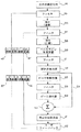
図1は、患者1および患者に取り付けられた加速度測定器の圧迫モニタ2を示している。加速度測定器による圧迫モニタは、圧迫深度を決定するために1つまたは複数の加速度測定器を使用する。加速度測定器による圧迫モニタの例は、我々の特許であるHalperin et al., CPR Chest Compression Monitor(心肺蘇生胸部圧迫モニタ)、米国特許6,390,996、2002年5月21日に見られる。参考のためそのままここに転載する。圧迫モニタ2を患者1の胸骨3の上、蘇生実施者の手か腕、または、自動心肺蘇生装置の上に配置する。そして胸部を圧迫する。加速度測定器は圧迫の加速度を測定し、プロセッサ4は加速度測定値に基づいて加速度測定器の実際位置変化を推定する。以下に示す信号処理技術は、推定の実際位置変化が正確で精密であることを確証する。
FIG. 1 shows a
推定の実際位置変化が位置変化ディスプレイ5に表示され、手での蘇生実施者や自動心肺蘇生装置に分かり易いフィードバック情報を提供する。同様に、他の心肺蘇生関連パラメータが1つまたは複数の圧迫装置のディスプレイに提供される(または別の手段で使用者にフィードバックされる)。心肺蘇生関連パラメータには、胸部圧迫深度、胸部圧迫速度、胸部圧迫加速度、および、患者心電図がある。 The estimated actual position change is displayed on the position change display 5 and provides easy-to-understand feedback information to the resuscitator by hand or the automatic cardiopulmonary resuscitation device. Similarly, other cardiopulmonary resuscitation related parameters are provided on the display of one or more compression devices (or otherwise fed back to the user). Cardiopulmonary resuscitation related parameters include chest compression depth, chest compression speed, chest compression acceleration, and patient electrocardiogram.
患者心電図の場合、1つまたは複数の電極から圧迫モニタに情報が提供される。胸部圧迫中、プロセッサは患者心電図を処理して推定の実際心電図を作成する。その後、推定の実際心電図は心電図ディスプレイ7(またはその他のフィードバック手段)に提供され、手での蘇生実施者、自動心肺蘇生装置、あるいは患者の心電図をモニタしているその他の人や装置に分かり易いフィードバック情報を提供する。 In the case of a patient electrocardiogram, information is provided to the compression monitor from one or more electrodes. During chest compression, the processor processes the patient's electrocardiogram and creates an estimated actual electrocardiogram. The estimated actual electrocardiogram is then provided to the electrocardiogram display 7 (or other feedback means) and is easily understood by the person performing the resuscitation by hand, the automated cardiopulmonary resuscitation device, or any other person or device monitoring the patient's electrocardiogram. Provide feedback information.
明細書の中で用いられている用語の定義を以下に記す。
実際圧迫深度:ある瞬間の実際の圧迫深度。
実際圧迫開始点:胸部圧迫が開始された実際の位置または点。
自動回帰移動平均:過去のデータサンプルを現在のデータサンプルの修正に使用する機能。
圧迫深度波形のベースライン位置:深度波形の実際開始点が最も多く集まっている位置。
ベースライン制限装置:圧迫深度波形のベースラインの位置で作動するプロセッサまたは機能。
圧迫ピーク:圧迫深度が最大になる位置または点。
現在の圧迫深度:ある瞬間の圧迫深度。
現在の開始点:現在の圧迫の開始点。
圧迫深度:圧迫された胸部のある瞬間の深度で、リラックスした胸部位置からの相対的な深さ。
推定の実際圧迫開始点:胸部圧迫が開始された実際位置または点の推定値。
圧迫の初期開始点:一連の胸部圧迫が開始された位置または点。
測定された圧迫開始点:胸部圧迫が開始された位置または点の測定値。
移動平均:過去のデータサンプルを現在のデータサンプルの修正に使用する機能。
過去の開始点:すでに観測された圧迫開始点。
圧迫深度波形のピーク位置:深度波形の実際ピーク位置が最も多く集まっている位置。
圧迫開始点:胸部圧迫が開始された位置または点。
Definitions of terms used in the specification are described below.
Actual compression depth: The actual compression depth at a certain moment.
Actual compression start point: The actual location or point where chest compressions started.
Automatic regression moving average: A function that uses past data samples to correct current data samples.
Baseline position of compression depth waveform: The position where the actual start points of the depth waveform are gathered the most.
Baseline limiter: A processor or function that operates at the baseline location of the compression depth waveform.
Compression peak: The position or point where the compression depth is maximum.
Current compression depth: The compression depth at a certain moment.
Current starting point: The starting point of the current compression.
Depth of compression: The depth at which a chest is compressed and the relative depth from the relaxed chest position.
Estimated actual compression start point: An estimate of the actual position or point where chest compressions were initiated.
Initial starting point of compression: The location or point at which a series of chest compressions began.
Measured compression start point: A measurement of the location or point where chest compressions were initiated.
Moving average: A function that uses past data samples to correct current data samples.
Past starting point: The compression starting point that has already been observed.
The peak position of the compression depth waveform: The position where the actual peak positions of the depth waveform are gathered most.
Compression start point: The position or point where chest compressions started.
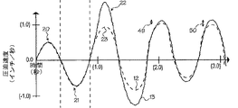
図2〜図4は、4つの仮説的圧迫の一期間の圧迫深度、速度、加速度のグラフを示している。図2〜図4に示されている波形のどれにも信号の処理は施されていない。図2の圧迫深度は陽性値―数値が大きいほど胸部は深く圧迫されている―として示されている。点線の波形12は圧迫深度、速度、加速度の実際波形を表している(加速度測定器にてそれぞれ独立して測定)。実線の波形13は圧迫モニタ加速度測定器にて測定された加速度から導き出された波形を表している。波形13はまた、圧迫モニタによって信号処理システム4に報告された波形である。圧迫深度は1インチ(2.5 cm)間隔でマークされたインチ単位で測定され、圧迫速度は1インチ/秒間隔でマークされた秒当たりのインチ(in/s)単位で測定され、圧迫加速度は1インチ/秒2間隔でマークされた秒2当たりのインチ(in/s2)単位で測定されている。3つの図すべてで、時間は1秒間隔でマークされた秒単位で測定されている。圧迫の開始は時間ゼロの時点である。圧迫の初期深度は深度ゼロの点である。
2-4 show graphs of compression depth, velocity, and acceleration over a period of four hypothetical compressions. No signal processing is performed on any of the waveforms shown in FIGS. The compression depth in FIG. 2 is shown as a positive value—the higher the value, the deeper the chest is compressed. A dotted line waveform 12 represents actual waveforms of compression depth, velocity, and acceleration (measured independently by an acceleration measuring instrument). A
点線14,15は3つのグラフすべてで交差している。点線14は最大圧迫深度が得られた時点に対応している。点線15は最小圧迫深度が得られた時点に対応している。さらに、点線14は圧迫深度最大16が圧迫速度ゼロに対応していることを示している。点線14はまた、加速度最大17が最大圧迫深度から少し外れていることを示している。同様に、点線15は圧迫最大18(または開始点またはゼロ点)が、圧迫速度ゼロに対応していることを示している。点線15はまた、加速度最小19が圧迫深度最小18から少し外れていることを示している。圧迫速度最大20および最小21は圧迫の中間点付近で認められる。
実線の波形は3つの主要な種類のエラーである信号エラー、外部加速度エラー、ドリフトを示している。信号エラーは、主に実線の波形の「ノイズ」(粗さ)に現れるが、外部加速度エラーも「ノイズ」となって現れることがある。加速度波形がノイズとしては小さくても、加速度全体には速度波形のノイズを大きくする作用がある。速度波形全体はやはりノイズの影響を大きくする。このように、図2の圧迫深度ノイズは図2の圧迫速度ノイズよりも大きくなり、したがって図4の圧迫加速度ノイズよりも大きくなる。すなわち、圧迫モニタは非常にノイズの多い圧迫深度波形を報告することになる。 The solid waveform shows the three main types of errors: signal error, external acceleration error, and drift. A signal error mainly appears in “noise” (roughness) of a solid waveform, but an external acceleration error may also appear as “noise”. Even if the acceleration waveform is small as noise, the entire acceleration has the effect of increasing the noise of the velocity waveform. The entire velocity waveform still increases the influence of noise. As described above, the compression depth noise in FIG. 2 is larger than the compression speed noise in FIG. 2, and is therefore larger than the compression acceleration noise in FIG. That is, the compression monitor will report a very noisy compression depth waveform.
外部加速度エラーは図2〜図4の実線の波形に主に大きな陽性スパイク22で現れる。(図2〜図4のスパイクは最大時に発生しているが、スパイクは圧迫サイクルのどこにでも発生し、加速度測定値に陽性にあるいは陰性に影響する)。スパイクは圧迫に関係のない大きな加速度で発生するが、加速度測定器で測定されてしまう。したがって、3つの図すべての実際波形は、対応するピーク23がスパイク22よりもはるかに小さくなっている。すなわち、ここに示す修正をしなければ、圧迫モニタはその圧迫サイクルにおいて圧迫深度が実際圧迫深度よりもはるかに大きいものとして報告してしまう。
The external acceleration error appears mainly as a large
ドリフトは主に、図2〜図4の矢印24,25で示されている実際の波形と報告された波形のそれぞれの最小値間の距離の増加で現れる。ドリフトは圧迫モニタが圧迫波形を誤って徐々に深くなっている(陽性ドリフト)と報告する原因となる。しかし、実際波形は最初の開始点付近に戻っていることから、図2〜図4に示すドリフトは陽性ドリフトとされる。同様に、図3と図4の矢印24,25は、報告された速度および報告された加速度に徐々に大きく影響することを示す。このドリフトの影響は、最初の圧迫開始点をすべての圧迫の信頼できる開始点として使用できないことを意味している。したがって、圧迫開始点は圧迫サイクルごとに決定しなければならない。さらに、その他のノイズ発生源を取り除くか十分小さくする必要がある。
Drift mainly appears as an increase in the distance between the actual waveform and the minimum value of each of the reported waveforms shown by
図5は、生の加速度を総圧迫深度の推定の実際値に変換する信号処理技術のフローチャートである。生の加速度34は、フィルタ処理済み加速度に変えるためステップ35の第1のフィルタでフィルタ処理される。第1のフィルタは高パス・フィルタからなり、ほとんどの形態の信号ノイズを大きく減少させる。(別の実施形態では、最初のフィルタをバンド・パス・フィルタ、移動平均フィルタ、無限インパルス・フィルタ、自動回帰フィルタ、自動回帰移動平均フィルタにすることができる)。図5に示すその他のステップの効果については図7〜図18との関連において記載する。
FIG. 5 is a flowchart of a signal processing technique for converting raw acceleration into an actual value of estimation of the total compression depth. The
図6は、生の圧迫加速度を推定の実際圧迫深度に変換する別の信号処理技術のフローチャートである。このフローチャートについては図7〜図18の説明の後に解説する。 FIG. 6 is a flowchart of another signal processing technique for converting raw compression acceleration into an estimated actual compression depth. This flowchart will be described after the description of FIGS.
フィルタ処理35の効果は図7〜図9に認められる。ここで、第1のフィルタステップ35の後の4つの仮定の圧迫について一期間の圧迫深度、速度、加速度を示している。(図7〜図9は第1のフィルタステップの出力を示す)。図9の測定された加速度波形13は、図4のフィルタ処理されていない対応する波形13よりもノイズがはるかに少ない。図8と図9の速度波形および深度波形は、ノイズの少ない加速度波形から導き出されている。それにもかかわらず、積分処理では速度波形が加速度波形よりもノイズが大きくなり、深度波形が速度波形よりもノイズが大きくなる。さらに、外部加速度スパイク22は、(矢印24,25で示すように)変動により生じたエラーのようにまだ残っている。
The effect of the filter processing 35 is recognized in FIGS. Here, the compression depth, velocity, and acceleration for one period are shown for the four hypothetical compressions after the first filter step 35. (FIGS. 7-9 show the output of the first filter step). The measured
図5に戻って、フィルタ処理された加速度は最初の積分ステップ36で積分され、圧迫速度が導き出される。しかし、図8に示すように、さらにフィルタ処理をしないと速度波形にはまだノイズが残る。このように速度は、フィルタ済み速度に変えるため2番目のフィルタステップ37でフィルタ処理される。2番目のフィルタは高パス・フィルタからなり、速度波形および深度波形のほとんどの信号ノイズをさらに減少させる。(別の実施形態では、2番目のフィルタをバンド・パス・フィルタ、移動平均フィルタ、無限インパルス・フィルタ、自動回帰フィルタ、自動回帰移動平均フィルタにすることができる)。
Returning to FIG. 5, the filtered acceleration is integrated by the
フィルタ処理37の効果は図10〜図12に認められる。ここで、2番目のフィルタステップ37の後の4つの仮定の圧迫について一期間の圧迫深度、速度、加速度を示している。(図10〜図12は2番目のフィルタステップ37の出力を示す)。図11の測定された速度波形13は図8の波形よりノイズが少ない。(最初のフィルタステップ後の速度波形)。深度波形は速度波形から導き出されているため、同様にノイズが少ない。それにもかかわらず、積分処理では加速度波形や速度波形よりも深度波形に少しノイズが多くなる。さらに、外部加速度スパイク22は、(矢印24,25で示すように)ドリフトにより生じたエラーのようにまだ残っている。
The effect of the filtering process 37 is recognized in FIGS. Here, for the four hypothetical compressions after the second filter step 37, the compression depth, velocity and acceleration for one period are shown. (FIGS. 10-12 show the output of the second filter step 37). The measured
図5に戻って、フィルタ処理された速度は2番目の積分ステップ38で積分され、胸部圧迫深度が計算される。信号ノイズは相当除去され3番目のフィルタステップは不要である。しかし、図10に示すように、深度波形のノイズは図11の速度波形のノイズよりまだ少し多い。したがって、別の実施形態では、深度波形のノイズをさらに減少させるために高パス・フィルタ、バンド・パス・フィルタ、その他からなる3番目のフィルタを使用することができる。
Returning to FIG. 5, the filtered velocity is integrated by the second integrating
最初のフィルタステップ(35と37)と積分ステップ(36と38)の後、ベースライン制限装置はステップ39の実際圧迫開始点を推定する。ベースライン制限装置は現在の圧迫開始点を推定するために、以下に記載する他の技術と共に、過去の圧迫における開始点を使用する。ベースライン制限装置そのものは、図10の圧迫深度波形のベースライン部分に基づいて作動するデジタルまたはアナログ信号プロセッサからなる。圧迫深度波形のベースライン部分は、実際開始点が最も多く集まっている位置の深度波形の部分から形成される。例えば、ベースラインは圧迫深度に等しい深度波形と1.1インチ(2.79 cm)低い深度波形の部分を形成する(圧迫の開始時点の大きな変化はまれで大きな変化を示す信号は恐らく異常である)。このように、制限装置は無視するか、あるいは現実的な深度値をその深度の1.1インチ上方に「開始点」を暫定的に割り当てる。1つの実施形態では、ベースラインより上方の過去の開始点を無視して、ベースラインより上方の現在の開始点を報告するか、エラーとして処理する。(過去の開始点はすでに観測された圧迫開始点のことである。現在の開始点とは現在の圧迫の開始点である。)別の実施形態では、ベースラインより上方の現在の開始点はまれなものとし、過去の開始点を平均化することができる。
After the initial filter steps (35 and 37) and integration steps (36 and 38), the baseline limiter estimates the actual compression start point of
別の実施形態では、ベースライン制限装置が、すべての開始点が深度波形のベースライン部分内に収まるように全開始点を移動平均して現在の圧迫の開始点を推定するようにする。移動平均とは、過去のデータサンプルを現在のデータサンプルの修正に使用する機能である。(その他の移動平均技術を以下に記す。)ベースライン制限装置の場合、ベースライン制限装置が過去の開始点より最近の開始点に重きを置く、すなわち時間の経過とともに開始点の重要度が低下するようにできる。深度波形のベースライン部分に入らない開始点には軽い重さを与えるか、または重さを与えない。すべての開始点に移動平均を適用することにより、ベースライン制限装置は外部加速度エラーやドリフトが現在の開始点に影響しないようにすることができる。言い換えれば、すべての開始点の移動平均は統計学的に、加速度の組み入れから導き出された現在の測定開始点よりも現在の実際開始点により近いことになる。 In another embodiment, the baseline limiter estimates the current compression start point by moving and averaging all start points such that all start points are within the baseline portion of the depth waveform. The moving average is a function that uses past data samples to correct the current data samples. (Other moving average techniques are described below.) In the case of a baseline limiter, the baseline limiter places more weight on the most recent starting point than the past starting point, ie the importance of the starting point decreases with time. You can do that. Start points that do not fall within the baseline portion of the depth waveform are lightly weighted or unweighted. By applying a moving average to all starting points, the baseline limiter can prevent external acceleration errors and drifts from affecting the current starting point. In other words, the moving average of all starting points is statistically closer to the current actual starting point than the current measuring starting point derived from the incorporation of acceleration.
以下は移動平均法の実施形態の一つの例である。この実施形態では、各圧迫開始点は1つ前の圧迫開始点に1.25%加算した重さ(重要度)にする。別の実施形態では、約0.1%から約12.5%の範囲(約1分後にはデータの重みが0.3%から90%の範囲になる)で重みをつけることができる。言い換えれば、現在の開始点の測定値(開始点1)は重みが100%、前回の開始点(開始点2)が重み98.75%、そのひとつ前の開始点(開始点3)が重み97.5%、そのひとつ前の開始点(開始点4)が重み96.25%、以後同様にすべての開始点に重みを付ける。最終的に遠い過去の圧迫には重みが全く加えられない。そして加重化された全開始点の深度を平均する。全開始点の加重平均を現在の開始点とし、また報告する。 The following is an example of an embodiment of the moving average method. In this embodiment, each compression start point has a weight (importance) obtained by adding 1.25% to the previous compression start point. In another embodiment, the weight may be in the range of about 0.1% to about 12.5% (the data weight will be in the range of 0.3% to 90% after about 1 minute). In other words, the measured value of the current start point (start point 1) has a weight of 100%, the previous start point (start point 2) has a weight of 98.75%, and the previous start point (start point 3) has a weight of 97.5%. The previous starting point (starting point 4) has a weight of 96.25%, and thereafter all starting points are similarly weighted. Finally, no weight is added to the distant past pressure. Then, the weighted depths of all starting points are averaged. Report the weighted average of all starting points as the current starting point and report.
別の実施形態では、事前に設定された特定の時間(例えば約1分から約15分)後のすべての圧迫を無視する。こうして、過去1〜15分内の圧迫のみを平均する。別の実施形態では、事前に設定された特定の圧迫回数(例えば約5回から約15回)後のすべての圧迫を無視する。 In another embodiment, all compressions after a pre-set specific time (eg, about 1 minute to about 15 minutes) are ignored. Thus, only the compressions in the past 1-15 minutes are averaged. In another embodiment, all compressions after a pre-set specific number of compressions (eg, about 5 to about 15) are ignored.
さらに例を挙げると、1つの実施形態では、開始点1の測定値= 0.5インチ、開始点2の測定値= 1.1インチ(2.79 cm)、開始点3の測定値= 4.0インチ、開始点4の測定値= 0.9インチであったとする。開始点3は深度波形のベースライン部分の範囲外(ベースライン部分は1.1インチでこの例ではその下である)である。この例でベースライン範囲外の開始点を無視することから、開始点3は無視される。このように、現在の開始点は以下のように報告される。
[(0.5*100%)+(1.1*98.75%)+(0.9*96.25%)] ÷ 3 = 0.853 インチ、
初期開始点に対する相対位置。
To further illustrate, in one embodiment,
[(0.5 * 100%) + (1.1 * 98.75%) + (0.9 * 96.25%)] ÷ 3 = 0.853 inches,
Relative to the initial starting point.
開始点3を移動平均の計算に含めると、現在の開始点は以下のように報告される。
[(0.5*100%)+(1.1*98.75%)+(4.0*97.5%)+(0.9*96.25%)] ÷ 4 = 0.853 インチ、
初期開始点に対する相対位置。
別の言い方をすれば、この値は現在の圧迫の推定の実際開始点である。
When starting
[(0.5 * 100%) + (1.1 * 98.75%) + (4.0 * 97.5%) + (0.9 * 96.25%)] ÷ 4 = 0.853 inch,
Relative to the initial starting point.
In other words, this value is the actual starting point of the current compression estimate.
数学的には、現在の開始点の報告値は以下のように表現される。
![]()
ここで、Dsは現在の開始点の深度、nrはベースラインを超えている開始点すべてを削除した後に残っている開始点の数、iは開始点の数(または加算指数)、DBiはith 番目の開始点の測定深度、ωは重み定数、Bはベースラインである。別の言い方をすれば、DBi*ωi-1 をiが1からnrまで加算し、その加算値をnrで割る。DBiがBより大きい場合、そのDBiはゼロとする。
Mathematically, the reported value for the current starting point is expressed as:
![]()
Where Ds is the depth of the current starting point, n r is the number of starting points remaining after deleting all starting points that exceed the baseline, i is the number of starting points (or addition index), and DBi is The measurement depth of the i th th starting point, ω is a weight constant, and B is a baseline. In other words, DB i * ω i−1 is added from 1 to n r and i is divided by n r . If DB i is greater than B, the DB i is zero.
ベースライン制限装置は、現在の開始点の推定深度の正確度と精密度をさらに向上させるため別の機能を発揮することもできる。例えば、現在の開始点とそのすぐ前の開始点の間の変化を確率で表すことができる。(同様に、現在の開始点と以前の開始点すべての移動平均の間の変化を確率で表すことができる。)大きな変化をした開始点の重みを、小さな変化の重みより小さくすることができる。この方法は「加重移動平均」法と呼ばれる。 The baseline limiter can also perform other functions to further improve the accuracy and precision of the estimated depth of the current starting point. For example, the change between the current start point and the immediately preceding start point can be expressed as a probability. (Similarly, the change between the current start point and the moving average of all previous start points can be expressed as a probability.) The weight of the start point with the large change can be made smaller than the weight of the small change. . This method is called the “weighted moving average” method.
上記の例を続けると、測定深度1は発生確率100%を持っているとみなす。そして、現在の開始点(深度1)と前回の開始点(深度2)の間の差は、1.1 - 0.5 = 0.6インチとなる。0.6インチとなるステップの確率は、以前の経験から97%とされる。確率が100%でないことから、現在の開始点が0.6インチ移動しているとみなすことはできない。その代わり、現在の開始点が0.6 * 0.97 = 0.582インチ移動しているとみなすことができる。したがって、加重移動平均を計算することにより、深度2は1.082インチであり1.1インチではないとみなすことができる。開始点3はここでも無視される。開始点2(1.1インチ)と開始点4(0.9インチ)の差は0.2インチで、99%の確率となる。このように、深度2と深度4のステップの有効距離は0.2*99% = 0.198となる。したがって、深度4は0.9インチではなく0.902インチとみなされる。上記と同じ移動平均を用いて、現在の開始点を以下のように報告できる。
[(0.5*100%)+(1.082*98.75%)+(0.902*96.25%)] ÷ 3 = 0.812 インチ、
初期開始点に対する相対位置。
別の言い方をすれば、この値は現在の圧迫の推定の実際開始点である。
Continuing the above example, we assume that
[(0.5 * 100%) + (1.082 * 98.75%) + (0.902 * 96.25%)] ÷ 3 = 0.812 inches,
Relative to the initial starting point.
In other words, this value is the actual starting point of the current compression estimate.
数学的には、現在の開始点の報告値は以下のように表現される。
![]()
ここで、Dsは現在の開始点の深度、nrはベースラインを超えている開始点すべてを削除した後に残っている開始点の数、iは開始点数、DBiはith 番目の開始点の測定深度、jはベースライン内にある最近のほとんどの開始点の指数、DBi-jはベースライン内にある最近のほとんどの開始点、PSはDBi - DBi-jの大きさのステップが生じる確率、ωは重み定数、Bはベースラインである。結果のDsは現在の開始点の報告深度である。別の言い方をすれば、[DBi-j+(DBi - DBi-j)*PS]*ωi-1 をiが1からnまで加算し、その加算値をnrで割る。DBiがB(ベースライン)より大きい場合、そのDBiはゼロとする。
Mathematically, the reported value for the current starting point is expressed as:
![]()
Where Ds is the depth of the current starting point, n r is the number of starting points remaining after deleting all starting points that exceed the baseline, i is the starting point number, DBi is the i th starting point Measurement depth, j is the index of most recent starting point in the baseline, DB ij is most recent starting point in the baseline, P S is the probability of a step of size DB i -DB ij , Ω is a weighting constant, and B is a baseline. The resulting Ds is the reported depth of the current starting point. In other words, [DB ij + (DB i −DB ij ) * P S ] * ω i−1 is added from 1 to n, and the added value is divided by n r . If DB i is greater than B (baseline), DB i is zero.
別の実施形態では、現在の開始点の深度と以前のすべての開始点の加重平均との間の段階の大きさ(step size)に確率を当てはめることができる。(上記の例で、確率は現在の開始点とひとつ前の開始点の間の段階の大きさに当てはめることができる)。この方法は「記憶式加重移動平均」法と呼ぶことができる。この方法では、現在の開始点の報告深度は数学的に以下のように表現される。

別の実施形態では、自動減衰移動平均(ARMA)フィルタをベースライン制限装置として使用できる。ARMAフィルタは、古いデータより最近のデータに重みをおく、指数関数的に衰えてゆく「忘却」フィルタである。ARMAは圧迫開始点またはピークの値以外にも作用する。というより、ARMAフィルタは短時間の間隔で得られた圧迫加速度、速度、あるいは深度のデータサンプルに作用する。データサンプルは1秒間に約100サンプルから約2000サンプルの割合で得られる(望ましくは1秒間に約1000サンプルの割合)。このように、ARMAフィルタは全波形に作用し、圧迫ピークや開始点のみに留まらない。 In another embodiment, an automatic attenuated moving average (ARMA) filter can be used as the baseline limiter. The ARMA filter is an “forgetting” filter that decays exponentially, weighting more recent data than older data. ARMA works not only on the compression start point or peak value. Rather, ARMA filters operate on compression acceleration, velocity, or depth data samples obtained at short intervals. Data samples are obtained at a rate of about 100 to about 2000 samples per second (preferably at a rate of about 1000 samples per second). In this way, the ARMA filter works on the entire waveform, not just the compression peak or starting point.
低いパス様式(ベースラインで高周波成分を除去)の場合、ARMAフィルタは数学的に以下のように表現される。
y[n] = (1-α)*y[n-1] + α*x[n].
For the low pass style (removing high frequency components at the baseline), the ARMA filter is mathematically expressed as:
y [n] = (1-α) * y [n-1] + α * x [n].
この場合、nは現在のサンプルの指標(nth番目のサンプル)、y[n]は現在のサンプルの出力、x[n]は現在のサンプルの入力、y[n-1]は1つ前のサンプルの出力、αはフィルタが過去の出力をどのくらいの速さで「忘れる」か、すなわち現在の入力が出力に及ぼす影響力の大きさを示す独立した用語である。αの値は約0.02から約0.0002の範囲に入り、0.002が多くの心肺蘇生関連フィルタの適用に適している。ベースライン制限装置のための高パスARMAフィルタを実施したい場合、ARMAの等式は以下のようになる。
y[n](high pass) = 1 - {(1-α)*y[n-1] + α*x[n]},
ここで、y[n](高パス)は高パス・フィルタ出力であり、その他の変数は低パスARMAフィルタの関連において定義される。高パス・フィルタは、深度、速度、あるいは加速度信号の低周波成分を除去するのに使用する。
In this case, n is the current sample index (the n th th sample), y [n] is the current sample output, x [n] is the current sample input, and y [n-1] is the previous one The sample output, α, is an independent term that indicates how fast the filter “forgets” past output, that is, how much influence the current input has on the output. The value of α is in the range of about 0.02 to about 0.0002, with 0.002 being suitable for many cardiopulmonary resuscitation related applications. If we want to implement a high pass ARMA filter for the baseline limiter, the ARMA equation is:
y [n] (high pass) = 1-{(1-α) * y [n-1] + α * x [n]},
Where y [n] (high pass) is the high pass filter output and other variables are defined in the context of the low pass ARMA filter. The high pass filter is used to remove the low frequency component of the depth, velocity, or acceleration signal.
上記の例の移動平均法は、圧迫深度波形の処理に関連して記載されている。しかし、圧迫の速度および加速度の正確な値を報告することが望まれている場合、この方法は速度波形および加速度波形の処理に使用できるに違いない。移動平均法は各波形に別々に適用できる。言い換えれば、移動平均法を加速度波形に適用し、次いで加速度波形を一体化し、次に2回目の移動平均法を速度波形に適用し、次に速度波形を一体化し、最後にする3回目の移動平均法を深度波形に適用する必要がない。しかし、別の実施形態では、この手順を使用することができる。 The moving average method of the above example has been described in connection with processing a compression depth waveform. However, if it is desired to report accurate values of compression speed and acceleration, this method must be usable for processing of velocity and acceleration waveforms. The moving average method can be applied to each waveform separately. In other words, the moving average method is applied to the acceleration waveform, then the acceleration waveform is integrated, then the second moving average method is applied to the velocity waveform, then the velocity waveform is integrated, and the final third movement There is no need to apply the averaging method to the depth waveform. However, in another embodiment, this procedure can be used.
ベースラインの信号を分析する別の方法を、推定の実際圧迫開始点の決定に使用することができる。ベースライン制限装置の別の実施形態には、移行確率マップを使用して測定開始点の特定のシフトの確率を確認する信号プロセッサからなる。(密度推定装置または核(カーネル)推定装置を使って確率マップを予め決定し、それから圧迫モニタソフトウェアにコードすることができる。)特定の開始点測定値を確率マップと比較し、システムは測定開始点の変動がどれほど間違っている(エラー)かを決定する。報告された開始点を適切に調整する。(同様に、移行確率マップは各圧迫の実際ピークおよび実際最大深度を推定するのに使用できる。) Another method of analyzing the baseline signal can be used to determine the estimated actual compression starting point. Another embodiment of the baseline limiter consists of a signal processor that uses a transition probability map to ascertain the probability of a particular shift in the measurement start point. (The probability map can be pre-determined using a density estimator or kernel estimator, and then coded into the compression monitor software.) The specific starting point measurement is compared to the probability map and the system starts the measurement Determine how wrong the point variation is (error). Adjust the reported starting point appropriately. (Similarly, the transition probability map can be used to estimate the actual peak and actual maximum depth of each compression.)
ベースライン制限装置39の効果は図13〜図15に認められる。ここでは、4つの仮定の圧迫について一期間の圧迫深度、速度、加速度を示している。図13〜図15はまた、図5のステップの出力(35〜39)を示している。ベースライン制限装置はステップ47の速度波形(図14)とステップ48の加速度波形(図15)に別々に適用される。
The effect of the
図13〜図15は、移動平均法が各圧迫における報告開始点のドリフトの影響を少なくすることを示している。(移動平均法はまた、波形のベースライン部分に現れる外部加速度エラーの影響を少なくする。)補正する前は、報告開始点が徐々に深くなってゆくのに対し、実際開始点は実際初期開始点に戻るように近づいて行った。移動平均法を測定した波形のベースラインに適用することにより、各圧迫で報告される開始点は統計学的に実際開始点に近づいてゆく。したがって、圧迫モニタは実際圧迫深度に近い推定の圧迫実深度を報告する。図2〜図4および図7〜12の矢印24,25よりも短い矢印49,50は、移動平均法を各波形に適用することの有益な効果を示している。
FIGS. 13-15 show that the moving average method reduces the effects of reporting start point drift at each compression. (The moving average method also reduces the effect of external acceleration errors that appear in the baseline portion of the waveform.) Before correction, the reporting start point gradually deepens, whereas the actual starting point is the actual initial start. Approached to return to the point. By applying the moving average method to the measured waveform baseline, the starting point reported in each compression is statistically closer to the actual starting point. Thus, the compression monitor reports an estimated actual compression depth that is close to the actual compression depth.
図5に戻って、ベースライン制限装置により補正された圧迫深度波形は、それに累積しているあらゆる信号ノイズを減少させるためにステップ50の第3のフィルタに通される。第3のフィルタは高パス・フィルタからなり、別の実施形態では第3のフィルタはバンド・パス・フィルタからなる。
Returning to FIG. 5, the compression depth waveform corrected by the baseline limiter is passed through a third filter in
引き続いて、深度波形(フィルタ処理の有無にかかわらず)がステップ52の開始点検出器に提供される。開始点検出器は現在の推定開始点の値を同定する。続いて現在の推定開始点は、(線54で示されるように)信号を組み合わせる手段53に提供される。信号組み合わせ手段53は、後で推定の実際圧迫深度を計算するために現在の推定開始点を使用する。信号組み合わせ手段は、信号追加装置、直線システムモデル、非直線システムモデル、あるいはその他の組み合わせ信号からなる。
Subsequently, the depth waveform (with or without filtering) is provided to the starting point detector at
次に、圧迫波形がステップ55のピーク制限装置に提供される。ピーク制限装置は、ベースライン制限装置と同じような機能を持つが、圧迫波形のピーク部分に作用する信号プロセッサである。波形のピーク部分とは、ピークが認められると思われる波形部分のことである。1つの実施形態では、ピーク部分はベースライン上方の波形部分のことである。ベースライン制限装置で使用した例を考えると、深度波形のピーク部分は1.1インチ(2.79 cm)上方の深度波形の部分である。このようにピーク制限装置は、ベースライン制限装置が波形のベースライン部分を滑らかにするように、波形のピーク部分を滑らかにする。
The compression waveform is then provided to the peak limiter at
1つの実施形態では、ピーク制限装置は最大圧迫深度の大きさの外側の境界を設定する。このように、ピーク制限装置は、既知の起こりそうもないピーク値よりも大きなピークすべてを無視する(捨て去る)か、すべてに適当な値を代入する(例えば、大きな体格の人の胸部深度は、心肺蘇生の圧迫深度にとって起こり得る値ではない)。このように、ピーク制限装置は圧迫モニタが起こりそうもない圧迫深度値を報告しないようにする。 In one embodiment, the peak limiter sets an outer boundary for the maximum compression depth magnitude. In this way, the peak limiter either ignores (throws away) all peaks that are larger than a known unlikely peak value, or assigns an appropriate value to all (for example, the chest depth of a large physique is Not a possible value for the compression depth of cardiopulmonary resuscitation). In this way, the peak limiter will not report compression depth values that are unlikely to cause compression monitoring.
ピーク制限装置の効果は図16〜図18にみられる。ここでは図5のピーク制限装置ステップ55の後の4つの仮説的圧迫における圧迫深度、速度、加速度のグラフを示している。(図16〜図18はステップ35〜55の出力を示している)。ピーク制限装置はステップ56の速度波形とステップ57の加速度波形に別々に適用されている。圧迫波形のピーク部分に移動平均法を適用することにより、外部加速度のスパイク22の影響が大きく抑えられる。前の処理ステップで考察した方法と合わせることにより、報告された波形は実際波形に近づく。
The effect of the peak limiter can be seen in FIGS. Here, a graph of compression depth, velocity, and acceleration in four hypothetical compressions after the
図5に戻って、残っている信号ノイズを取り除くため、推定ピークをオプションで第4のフィルタ58に提供することができる。第4のフィルタは高パス・フィルタからなり、別の実施形態では第4のフィルタはバンド・パス・フィルタまたはその他のフィルタからなる。
Returning to FIG. 5, an estimated peak can optionally be provided to the
それに引き続き、深度波形がステップ59のピーク検出器に提供される。ピーク検出器は推定ピーク(現在の圧迫の推定最大深度)の値を特定する。次に、推定ピークは信号組み合わせ手段53に提供される。信号組み合わせ手段53は、推定開始点52を推定ピーク59と合わせて、現在の圧迫61の推定の実際圧迫深度を提供する。次に推定の実際深度はユーザフィードバック手段62(ユーザフィードバック装置)に提供される。ユーザフィードバック手段は、スピーカー、視覚ディスプレイ、1つまたは複数のLED、振動機、ラジオ、その他の蘇生実施者に伝達する手段からなる。ユーザフィードバック装置はまた、現在の圧迫の推定の実際深度に関する情報を蘇生実施者に提供する。
Subsequently, the depth waveform is provided to the peak detector in
図5の方法において、ベースライン部分およびピーク部分は重ならない。このように、圧迫深度波形はベースライン部分とピーク部分の2つの部分から構成されていると考えられる。深度波形の各部分は、異なる情報を抽出するために2つの異なる手順(ベースライン制限装置およびピーク制限装置)で別々に処理される。このように、ベースライン制限装置とピーク制限装置の両方が同じ深度波形に作用する。これの効果は、深度波形を形成している信号がまずベースライン制限装置に、次にピーク制限装置に提供されることにある(信号を分割しない)。 In the method of FIG. 5, the baseline portion and the peak portion do not overlap. Thus, the compression depth waveform is considered to be composed of two parts, a baseline part and a peak part. Each part of the depth waveform is processed separately in two different procedures (baseline limiter and peak limiter) to extract different information. Thus, both the baseline limiter and the peak limiter act on the same depth waveform. The effect of this is that the signal forming the depth waveform is first provided to the baseline limiter and then to the peak limiter (does not split the signal).
図6に示した方法は、ベースライン部分およびピーク部分が重なった場合に使用される(しかし、この方法はベースライン部分およびピーク部分が重なっていない場合にも使用される)。例えば、図6の方法は、ベースライン部分が(胸部がリラックスしている状態に比べて)1.5インチ上方に設定され、ピーク部分が(胸部がリラックスしている状態に比べて)1.0インチ上方に設定されている場合に使用される。この場合、深度波形を代表している信号が分割され、ベースライン制限装置とピーク制限装置の2つの別々のプロセッサに提供される各プロセッサはすでに説明している制限装置と同じ機能を実行する。このように、ベースライン制限装置とピーク制限装置は互いに独立して作動するが、図6の方法は、図5に示す方法とほぼ同じように、推定開始点と推定ピークを生成する。信号を組み合わせるための方法は、次に現在の圧迫の推定の実際深度を生成するためにステップ53の推定開始点および推定ピークを結合させる。現在の圧迫の推定の実際深度はステップ62のユーザフィードバック装置に提供される。ユーザフィードバック装置はまた、現在の圧迫の推定の実際深度を蘇生実施者に提供する。
The method shown in FIG. 6 is used when the baseline and peak portions overlap (but this method is also used when the baseline and peak portions do not overlap). For example, in the method of FIG. 6, the baseline portion is set 1.5 inches above (compared to the chest being relaxed) and the peak portion is 1.0 inches above (relative to the chest being relaxed). Used when set. In this case, the signal representing the depth waveform is split and each processor provided to two separate processors, the baseline limiter and the peak limiter, performs the same function as the limiter already described. In this way, the baseline limiter and the peak limiter operate independently of each other, but the method of FIG. 6 generates an estimation start point and an estimated peak in much the same way as the method shown in FIG. The method for combining signals then combines the estimated starting point and estimated peak of
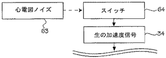
図5および図6の信号処理法に加えて、別の技術を圧迫深度波形のエラーを修正するために使用することもできる。例えば、図19は、加速度測定器が加速度測定をいつ開始するかを代わってコントロールするスイッチ64をオンにするのに心電図ノイズ63の変化を使用する信号処理技術のフローチャートである。
In addition to the signal processing methods of FIGS. 5 and 6, other techniques can be used to correct compression depth waveform errors. For example, FIG. 19 is a flowchart of a signal processing technique that uses changes in the electrocardiogram noise 63 to turn on a
この方法を実施するために、圧迫モニタには患者心電図を測定するために、1つまたは複数の電極もしくはその他の手段が提供されている。蘇生実施者が胸部を圧迫するたびに、患者心電図にノイズが入る。患者の実際心電図が(電気活性を示さない)平坦であって、報告される心電図には胸部圧迫によるノイズが示される。事実、体動によるアーチファクトの信号(胸部圧迫による心電図のノイズ成分)が心電図の律動に組み入れられる。実際心電図律動がどうであっても、心電図ノイズが分離されて得られる。 To implement this method, the compression monitor is provided with one or more electrodes or other means for measuring the patient's electrocardiogram. Every time the resuscitator presses on the chest, noise enters the patient's ECG. The patient's actual ECG is flat (not showing electrical activity) and the reported ECG shows noise due to chest compressions. In fact, an artifact signal due to body movement (an electrocardiogram noise component due to chest compression) is incorporated into the electrocardiogram rhythm. Whatever the electrocardiogram rhythm is actually, the electrocardiogram noise is obtained separately.
胸部圧迫中に大量の心電図ノイズが生じることから、圧迫の開始点は心電図ノイズが事前に設定された閾値を越える点に関連付けられる。しかしながら、圧迫の動作と心電図のノイズの発生の間にいくらかの遅れあるいはずれが生じる。時間のずれはミリ秒から10分の1秒の単位である。圧迫のいずれの部分も逃さないために、バッファ(デジタル、アナログのいずれでも)を適用して時間のずれを修正する。その後、心電図のノイズが特定の閾値を越えると、加速度測定器が作動する(そして加速度測定値を得始める)ようにスイッチをプログラムする。測定加速度を2回積分することにより総圧迫深度を決定する。 Since a large amount of ECG noise occurs during chest compression, the starting point of compression is associated with the point where the ECG noise exceeds a preset threshold. However, there will be some delay or deviation between the compression action and the occurrence of ECG noise. The time lag is in units of milliseconds to 1 / 10th of a second. In order not to miss any part of the compression, a buffer (either digital or analog) is applied to correct the time lag. Thereafter, when the ECG noise exceeds a certain threshold, the switch is programmed to activate the accelerometer (and begin to obtain an acceleration measurement). The total compression depth is determined by integrating the measured acceleration twice.
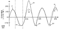
圧迫開始点を確立するための基準センサとして心電図ノイズを使用する効果は、4つの仮説的圧迫における一定期間の圧迫深度、速度、加速度を示す図20〜図25に認められる。図20〜図22の波形には信号の処理が何もなされていない。点線の波形12は、圧迫深度、速度、(加速度測定器とは独立して測定された)加速度の実際波形を表し、実線の波形は加速度測定器にて測定された加速度から導き出された波形を表している。実線の波形13は圧迫モニタにより報告された波形でもある。信号ノイズの影響は実線の波形の粗さに現れている。外部加速度ノイズの影響は、報告された波形中の2つのスパイク65,66に現れている。(徐々に圧迫が浅くなる)陰性ドリフトの影響は、報告された波形や実際波形の最小値間の(矢印67,68で表される)距離が増大することに認められる。
The effect of using electrocardiographic noise as a reference sensor to establish a compression start point can be seen in FIGS. 20-25, which show compression depth, velocity, and acceleration over a period of time in the four hypothetical compressions. No signal processing is performed on the waveforms in FIGS. The dotted waveform 12 represents the actual waveform of the compression depth, velocity, and acceleration (measured independently of the acceleration measuring instrument), and the solid waveform represents the waveform derived from the acceleration measured by the acceleration measuring instrument. Represents. The
圧迫開始点を確立するための基準センサとして心電図ノイズを使用する効果は、仮説的圧迫における一定期間の圧迫深度、速度、加速度のグラフを示す図23〜図25に認められる。基準センサとして心電図ノイズを用いることにより、外部加速度のある種のエラーが減少し、陰性ドリフトの影響が小さくなる。(心電図ノイズ基準センサは陽性ドリフトの影響も小さくすることができる)。特に心電図ノイズ基準センサは、圧迫最小値近くで起こる外部加速度ノイズの影響を小さくする。加速度測定器の電源が「オン」になっていないと、外部加速度のスパイク部分は「無視」される。実際には、加速度測定器がデータをまだ収集していても、心電図ノイズが設定レベルに達していない期間に発生する加速度データあるいは信号をソフトウェアまたはハードウェアによって除外される。別の方法では、心電図ノイズが予め設定されている閾値内になったときに、推定の実際圧迫深度を計算する。いずれの場合でも、報告される波形の中のスパイク65の影響を小さくする。しかし、加速度測定器それ自身は圧迫関係の加速度と外部加速度の違いを区別できない。このように、報告される波形にはスパイク66にみられるように圧迫動作中に起こった外部加速度ノイズが含まれることがある。
The effect of using ECG noise as a reference sensor for establishing a compression start point can be seen in FIGS. 23-25, which show graphs of compression depth, velocity, and acceleration over a period of time in hypothetical compression. By using ECG noise as a reference sensor, certain errors of external acceleration are reduced and the negative drift effect is reduced. (The ECG noise reference sensor can also reduce the effect of positive drift). In particular, the ECG noise reference sensor reduces the influence of external acceleration noise that occurs near the minimum compression value. If the accelerometer is not “on”, the external acceleration spike is “ignored”. In practice, even if the accelerometer is still collecting data, acceleration data or signals that occur during periods when ECG noise has not reached the set level are excluded by software or hardware. Another method calculates the estimated actual compression depth when the ECG noise falls within a preset threshold. In either case, the effect of spike 65 in the reported waveform is reduced. However, the accelerometer itself cannot distinguish between compression-related acceleration and external acceleration. Thus, the reported waveform may include external acceleration noise that occurred during the compression operation, as seen in
そうではあるが、心電図ノイズ基準センサはドリフトの影響を小さくする。圧迫開始点を独立して確立することにより、波形が陽性ドリフトや陰性ドリフトのいずれかに至ることがはるかに小さくなる。言い換えると、加速度測定器は常に圧迫が実際に開始された後の加速度を測定する。このように、図23の報告波形は、蘇生実施者が実際何を行っているか、すなわち徐々に深くなってゆく開始点から圧迫していることをもっと明らかに示している。このように、ピーク69,70は測定された波形が実際波形ともっと強く一致していることを示している。 Nevertheless, the ECG noise reference sensor reduces the effects of drift. Establishing the compression start point independently makes it much less likely that the waveform will reach either a positive or negative drift. In other words, the accelerometer always measures the acceleration after the compression is actually started. Thus, the reported waveform of FIG. 23 shows more clearly what the resuscitation practitioner is actually doing, that is, squeezing from the starting point that gradually gets deeper. Thus, peaks 69 and 70 indicate that the measured waveform more closely matches the actual waveform.
心電図ノイズ基準センサはドリフトの影響を小さくし、ある種の外部加速度ノイズを減少させることができるが、信号ノイズの問題は残されたままである。したがって、図23〜図25は依然として図20〜図22に示されている信号ノイズと同じレベルを示している。すべての形態のノイズを減少させるため、心電図ノイズ基準センサを図5または図6の信号処理技術と組み合わせることができる。複合技術により実際波形に近い報告深度波形になる。 The ECG noise reference sensor can reduce the effects of drift and reduce some external acceleration noise, but the problem of signal noise remains. Accordingly, FIGS. 23-25 still show the same level as the signal noise shown in FIGS. 20-22. To reduce all forms of noise, an ECG noise reference sensor can be combined with the signal processing techniques of FIG. 5 or FIG. The combined technique results in a reported depth waveform that is close to the actual waveform.
その他の基準センサを用いて圧迫の実際開始点を確立することができる。図26は、平面80に横たわっている患者1に取り付けた、加速度測定器に基づく圧迫モニタを示している。加速度測定器81、荷重センサ82、スイッチ83からなる基準センサのシステムは、各センサが胸部圧迫に関する様々なパラメータを測定できるように配置されている。基準加速度測定器の場合、基準加速度測定器を患者の体表、または患者と同じ外部加速度が発生する基準物体の上に配置する。基準加速度測定器は3つの軸からなる加速度測定器からなるが、その他に1つの軸からなる加速度測定器を3つ用いて互いに軸を直交させるか、または1つの軸からなる加速度測定器1つを用いる(この場合、他の2つの軸方向の加速度は無視できるものとする)こともできる。
Other reference sensors can be used to establish the actual starting point of compression. FIG. 26 shows a compression monitor based on an accelerometer attached to a
基準加速度測定器81は、信号プロセッサが患者の搬送により生じるこれらの加速度のような外部加速度エラーを除外するようにする。1つの方法は、圧迫モニタまたは自動心肺蘇生装置(デバイス加速度)により感知された加速度を信号プロセッサに提供する。デバイス加速度には、圧迫により生じた加速度(圧迫加速度)および外部加速度により生じた加速度(外部加速度)が含まれる。次に、基準加速度測定器または加速度測定器が信号プロセッサに基準加速度を提供する。基準加速度測定器には患者の外部加速度のみが含まれる。それから、基準加速度は推定の実際加速度を生成するためにデバイス加速度と組み合わされる。(基準加速度に対する圧迫加速度の影響は、平面および患者が圧迫モニタに対して動かないため、無視できる。) The reference acceleration meter 81 causes the signal processor to filter out external acceleration errors such as those accelerations caused by patient transport. One method provides the signal processor with the acceleration sensed by the compression monitor or automatic cardiopulmonary resuscitation device (device acceleration). The device acceleration includes acceleration caused by compression (compression acceleration) and acceleration caused by external acceleration (external acceleration). A reference accelerometer or accelerometer then provides a reference acceleration to the signal processor. The reference accelerometer includes only the patient's external acceleration. The reference acceleration is then combined with the device acceleration to produce an estimated actual acceleration. (The effect of compression acceleration on reference acceleration is negligible because the plane and patient do not move relative to the compression monitor.)
一旦獲得したら、推定の実際加速度は推定の実際胸部深度を得るために2回統合される(integrated)。このように、圧迫深度は大きな外部加速度があっても決定される。さらに位置信号は、実際加速度を図5および図6の信号処理法または他の信号処理法と組み合わせることによりもっと正確かつ精密にすることができる。 Once acquired, the estimated actual acceleration is integrated twice to obtain the estimated actual chest depth. Thus, the compression depth is determined even when there is a large external acceleration. Furthermore, the position signal can be made more accurate and precise by combining the actual acceleration with the signal processing methods of FIGS. 5 and 6 or other signal processing methods.
心電図ノイズセンサおよび基準加速度測定器の代わりに(または追加として)、別の基準センサを実際圧迫開始点の設定に使用することができる。基準センサは、荷重センサ82、スイッチ83、経胸腔インピーダンス検出器、(上記に記載の)心電図ノイズ検出器、自動心肺蘇生装置中の電圧または電流センサ、自動心肺蘇生装置中の開始信号、自動心肺蘇生装置中のエンコーダ、あるいは圧迫の実際開始を独立して検出可能なその他のセンサからなる。基準センサが圧迫の開始を検出すると開始点がゼロにセットされる。それから加速度が処理されて圧迫深度が導き出される。基準センサが圧迫の開始を検出したとき開始点をゼロに設定する技術を、図5および図6の信号処理技術と組み合わせることができる。
Instead of (or in addition to) the ECG noise sensor and the reference accelerometer, another reference sensor can be used to set the actual compression start point. Reference sensors include
スイッチ83について言えば、圧迫が始まるとスイッチが閉じられるようにスイッチを配置することができる。例えば、スイッチは圧迫モニタの下または上、患者1の上、患者が横になっている平面80の上、蘇生実施者の手、心肺蘇生装置の上、患者の上、その他圧迫が始まったことをスイッチが察知できる部位に配置することができる。
As for the switch 83, the switch can be arranged so that the switch is closed when compression starts. For example, the switch may be under or above the compression monitor, on the
スイッチは様々な種類のスイッチとセンサから構成される。それらには、接触スイッチ、動作スイッチ、自動心肺蘇生装置上の電圧センサ、自動心肺蘇生装置上の光学式、回転式またはその他のエンコーダ、シャフトなど自動心肺蘇生装置の構成要素の位置変化計、電位差計、ひずみゲージ、圧電抵抗トランスデューサ、差動変圧器、同期電導電位差計、様々な電導および様々な電気抵抗の感知器、過電流非電導トランスデューサー、容量トランスデューサ、電気光学トランスデューサ、写真スイッチ、ビデオテープスイッチ、ホログラフィースイッチ、光弾性技術、並進運動エンコーダ、超音波トランスデューサ、移動コイルおよび移動磁石感知、交流または直流タコメータ、過電流ドラグカップタコメータ、その他の加速度測定器、または位置変化スイッチがある。 The switch is composed of various types of switches and sensors. They include contact switches, motion switches, voltage sensors on automatic cardiopulmonary resuscitation devices, optical on automatic cardiopulmonary resuscitation devices, rotary or other encoders, position change meters for components of automatic cardiopulmonary resuscitation devices such as shafts, potential differences Meters, strain gauges, piezoresistive transducers, differential transformers, synchronous conductivity potentiometers, various conducting and various electrical resistance sensors, overcurrent non-conducting transducers, capacitive transducers, electro-optic transducers, photographic switches, videotapes There are switches, holographic switches, photoelastic techniques, translational encoders, ultrasonic transducers, moving coil and moving magnet sensing, AC or DC tachometers, overcurrent drag cup tachometers, other accelerometers, or position change switches.
荷重センサ82の場合、荷重センサは蘇生実施者、患者、自動心肺蘇生装置、患者の下、または圧迫が始まるときに荷重センサが荷重状況を感知するようなその他の部位に接続される。荷重状況に関する荷重センサの測定値が事前に定められた閾値を越えたとき、測定開始点がゼロに設定される。荷重センサは荷重センサが荷重状況を感知したときに活性化されるスイッチに操作上接続されるか、単に信号処理システム識別装置(詳細は以下に記す)に信号を送る。圧迫深度は加速度を2回積分されて決定される。荷重センサが圧迫の開始を検出したとき開始点をゼロに設定する技術を、図5および図6の信号処理技術と組み合わせることができる。
In the case of
荷重センサ82の別の実施形態では、荷重センサを患者の体重および圧迫力の両方を感知できるように配置することができる。荷重センサ82は患者が横になっている台80の下に配置することができる。圧迫中、患者を押す力により荷重センサは患者の体重よりも大きな総合力を報告することになる。したがって、総合力が患者の体重にほぼ等しいときに開始点がゼロに設定される。
In another embodiment of the
この技術とともに使用できる力センサの例には、圧力センサ、弾性力トランスデューサ、自動心肺蘇生装置のシャフトの位置変化計、自動心肺蘇生装置の電圧または電流センサ、自動心肺蘇生装置の光学的、回転式あるいはその他のエンコーダ、固定したひずみゲージ、光線ひずみゲージ、差動変圧器、圧電トランスデューサ、様々な電気抵抗/FM発振器、ジャイロスコープ圧力トランスデューサ、振動ワイヤー力検出器などがある。この技術とともに使用できる圧力センサの例には、重量品計測器、マノメータ、弾性トランスデューサ、圧電トランスデューサ、力平衡トランスデューサなどがある。 Examples of force sensors that can be used with this technology include pressure sensors, elastic force transducers, automatic cardiopulmonary resuscitation device shaft position changers, automatic cardiopulmonary resuscitation device voltage or current sensors, automatic cardiopulmonary resuscitation device optical, rotary Or other encoders, fixed strain gauges, beam strain gauges, differential transformers, piezoelectric transducers, various electrical resistance / FM oscillators, gyroscope pressure transducers, vibrating wire force detectors, etc. Examples of pressure sensors that can be used with this technology include heavy goods measuring instruments, manometers, elastic transducers, piezoelectric transducers, force balance transducers, and the like.
経胸腔的インピーダンス検出器の場合、1つあるいは複数の心電図用電極、心房細動用電極、またはその他の電極を患者の胸壁に配置する。圧迫を開始すると、胸壁のインピーダンスが変化する。胸壁インピーダンスはどれでも2つの電極の間にある皮膚および胸腔内構造物によるインピーダンスからなる。胸部インピーダンスの変化は、小さな試験電流あるいはインピーダンスを測定するその他の方法で測定される。インピーダンスが事前に設定された量だけ変化したときに、開始点がゼロに設定される。測定加速度を処理することにより総圧迫深度を決定できる。 In the case of a transthoracic impedance detector, one or more electrocardiogram electrodes, atrial fibrillation electrodes, or other electrodes are placed on the patient's chest wall. When compression is started, the impedance of the chest wall changes. Any chest wall impedance consists of impedance due to skin and intrathoracic structures between the two electrodes. Changes in chest impedance are measured with a small test current or other method of measuring impedance. The starting point is set to zero when the impedance changes by a pre-set amount. The total compression depth can be determined by processing the measured acceleration.
圧迫モニタが圧迫波形を測定できることから、特定の圧迫波形を実行するとき圧迫モニタを蘇生実施者あるいは自動心肺蘇生装置の誘導とすることができる。図27は、圧迫モニタが蘇生実施者に実施を先導する圧迫波形を示している。深度はインチで測定され、時間は秒で刻まれる。図27の目盛りは0.5秒間隔、1.0インチ間隔で印が付いている。サイクルの圧迫段階は、陽性に傾斜した曲線84として示される。サイクルの圧迫段階は最大圧迫深度85(圧迫ピーク)で終了する。サイクルの圧迫解除段階は、陰性に傾斜した曲線86として示される。圧迫解除段階は蘇生実施者が次の開始点87(またはベースライン)で新たに圧迫を開始するときに終了する。この開始点は最初のものと異なることもある。圧迫は、時間=0、深度=0で開始され、圧迫の総深度は矢印88で示されている距離である。
Since the compression monitor can measure the compression waveform, the compression monitor can be the resuscitation practitioner or the guidance of an automatic cardiopulmonary resuscitation device when executing a specific compression waveform. FIG. 27 shows a compression waveform where the compression monitor leads the implementation to the resuscitation practitioner. Depth is measured in inches and time is in seconds. The scale in Figure 27 is marked at 0.5 second intervals and 1.0 inch intervals. The compression phase of the cycle is shown as a positively sloped
圧迫波形には、蘇生実施者が最大圧迫深度で短時間同じ位置を保つ圧迫保持期間89が認められ、蘇生実施者が最初の開始点より深い点で短時間位置を保つ不完全圧迫解除維持期間90が認められる。それぞれの圧迫および圧迫解除は、圧迫段階84および圧迫解除段階86の比較的急峻な波形で示されるように速い加速度と速度ですばやく実施される。デューティサイクルは50%より少し低い(圧迫と圧迫解除の時間の比は1)。これは、矢印89間の距離によって示されるように圧迫段階に費やされる時間は矢印90間の距離によって示されるように圧迫解除ステップに費やされる時間より少し短いことを意味している。
The compression waveform shows a
図27の圧迫波形は、圧迫モニタが蘇生実施者に圧迫するための指示を与えることができる特定の波形の例を示しているが、別の波形になる可能性もある、例えば、別の波形では圧迫保持時間が認められないことがある。さらに別の波形ではデューティサイクルが異なったり、圧迫保持時間が増加したりすることもある。正確な波形は、特定の患者に対する最適の圧迫波形を構成する圧迫波形の種類に関する現在の科学水準にかかっている。加えて、圧迫モニタにはスイッチ、ボタン、ソフトウェア、あるいは蘇生実施者が患者の体格や体形を入力できるようにするためのその他のユーザ入力手段を装備することができる。圧迫モニタは、波形ライブラリから特定の波形を選択するのにこの情報を使用できる。圧迫波形は将来の検討、AHAガイドライン、蘇生実施者の注意事項、医療専門家の参考のための所見として採用できる。したがって、下記に詳しく記すように、様々なときに異なる波形がユーザフィードバック装置に提供される。 The compression waveform in FIG. 27 shows an example of a specific waveform that the compression monitor can give instructions to the resuscitator to compress, but may be another waveform, for example, another waveform. In some cases, pressure retention time may not be allowed. Still another waveform may have a different duty cycle or increased compression hold time. The exact waveform depends on current scientific standards regarding the type of compression waveform that makes up the optimal compression waveform for a particular patient. In addition, the compression monitor can be equipped with switches, buttons, software, or other user input means to allow the resuscitator to enter the patient's physique and shape. The compression monitor can use this information to select a particular waveform from the waveform library. The compression waveform can be used for future consideration, AHA guidelines, resuscitation notices, and findings for medical professional reference. Accordingly, as will be described in detail below, different waveforms are provided to the user feedback device at various times.
ユーザフィードバック装置により先導用波形が提供される(図5のステップ62)。さらに、ユーザフィードバック装置は蘇生実施者または自動心肺蘇生装置に圧迫関連情報を提供する。例えば、ユーザフィードバック装置は圧迫開始点、圧迫深度波形、圧迫速度波形、圧迫加速度に関する情報を表示することができる。このように、ユーザフィードバック装置は蘇生実施者または自動心肺蘇生装置に、心肺蘇生のすべての段階を通して、胸部の位置、速度、加速度の状況を確認するのに必要なすべてのデータを提供できる。この情報はまた、蘇生実施者または自動心肺蘇生装置の実施状況を評価するのに使用できる。
A leading waveform is provided by the user feedback device (
ユーザフィードバック装置は、蘇生実施者または自動心肺蘇生装置に圧迫ステップの質および圧迫解除段階の質に関する情報を提供する。圧迫段階の質は、総圧迫深度、デューティサイクル、圧迫の加速度、圧迫の滑らかさ、圧迫段階に関連するその他の因子に関する圧迫の品質である。圧迫解除段階の質は、蘇生実施者が実際開始位置に戻ってくるかどうか、デューティサイクル、圧迫解除の加速度、圧迫解除の滑らかさ、圧迫解除段階に関連するその他の因子に関する圧迫の品質である。蘇生実施者または自動心肺蘇生装置は、圧迫の種類および品質を評価あるいは先導するためにこの情報を使用する。 The user feedback device provides information about the quality of the compression step and the quality of the compression release phase to the resuscitation practitioner or automatic cardiopulmonary resuscitation device. The quality of the compression phase is the quality of the compression with respect to the total compression depth, duty cycle, compression acceleration, compression smoothness, and other factors associated with the compression phase. The quality of the pressure relief phase is the quality of the pressure in terms of whether the resuscitator actually returns to the starting position, duty cycle, pressure relief, pressure relief smoothness, and other factors related to the pressure relief phase. . The resuscitation practitioner or automated cardiopulmonary resuscitation device uses this information to assess or guide the type and quality of the compression.
ユーザフィードバック装置62は、加速度、速度、位置の波形から得られた情報を組み合わせて、蘇生実施者または自動心肺蘇生装置に圧迫ステップの質に関する情報を提供する。例えば、ユーザフィードバック装置は、圧迫深度が推奨ガイドラインよりも小さい場合は圧迫する力を増すように、また圧迫深度が推奨ガイドラインよりも大きい場合は圧迫する力を減らすように蘇生実施者に指示を出す。ユーザフィードバック装置は、圧迫波形のその他の圧迫ステップパラメータに関して蘇生実施者に指示を出す。例えば、ユーザフィードバック装置は、適切な圧迫深度を達成するのに圧迫時間が短すぎるか長すぎるかについて、蘇生実施者または自動心肺蘇生装置に情報を与える。
The
ユーザフィードバック装置62は、加速度、速度、位置の波形から得られた情報を組み合わせて、蘇生実施者または自動心肺蘇生装置に圧迫解除ステップの質に関する情報を提供する。例えば、ユーザフィードバック装置はユーザや装置に、圧迫解除後の適切な待機位置に関する指示を与える。このように、ユーザフィードバック装置は、蘇生実施者または装置が胸部を最初の開始位置まで十分戻らせていない場合に、ユーザまたは装置に胸部を十分リラックスさせることを指示できる。逆に医学的に示される必要がある場合、ユーザフィードバック装置はユーザまたは装置に最初の胸部位置の真下の深度まで戻るよう指示できる。この場合、蘇生実施者または装置は圧迫解除維持時間に入り、圧迫サイクルが最小深度の時間になっても胸部に一定の力を加え続ける。その他の場合として、ユーザフィードバック装置は別の時間に異なる圧迫開始点を示すことができる。このように、ユーザフィードバック装置は蘇生実施者または装置に、圧迫サイクル中、不完全な圧迫解除維持時間を適用するが、換気中には十分リラックスした位置に戻るように指示することができる。ユーザフィードバック装置は蘇生実施者または装置に、圧迫解除の割合と圧迫解除段階のデューティサイクルなど、その他の圧迫解除段階のパラメータに関して指示することができる。
The
これらを一緒にして、圧迫段階の質および圧迫解除段階の質から得られた情報はユーザフィードバック装置が最適な圧迫波形および最適の圧迫デューティサイクルを作るよう蘇生実施者を誘導できるようにする。蘇生実施者は、事前に設定された深度と割合で圧迫し、事前に設定された圧迫深度で事前に設定された時間だけ胸部を保持することで特定の圧迫波形を実施する。蘇生実施者は、事前に設定された時間だけ胸部を圧迫し、別の事前に設定された期間胸部をリラックスさせることで特定のデューティサイクルを実施する。 Together, the information obtained from the quality of the compression phase and the quality of the compression phase allows the user feedback device to guide the resuscitation practitioner to produce the optimal compression waveform and optimal compression duty cycle. The resuscitation practitioner performs a specific compression waveform by compressing at a preset depth and rate and holding the chest for a preset time at a preset compression depth. The resuscitation practitioner performs a specific duty cycle by squeezing the chest for a preset time and relaxing the chest for another preset time period.
このように、ユーザフィードバック装置は蘇生実施者または自動心肺蘇生装置が圧迫サイクルの各段階(圧迫および圧迫解除)を適切な圧迫の割合、圧迫深度、圧迫速度(患者の圧迫および圧迫解除にかかる時間)、圧迫加速度、圧迫保持時間で実施するように誘導することができる。したがって、蘇生実施者または装置が実際に適用する圧迫波形は複合圧迫波形を形成することができる。ほとんどの患者がより複雑な波形から益を受けていることを研究で示されていることから、自動心肺蘇生装置が圧迫モニタをこのユーザフィードバック装置とともに使用するなら、患者の生存率は上昇すると思われる。 In this way, the user feedback device allows the resuscitator or automatic cardiopulmonary resuscitation device to step through the compression cycle (compression and decompression) at the appropriate rate of compression, compression depth, and compression speed (the time it takes for the patient to compress and release). ), It can be guided to be carried out with compression acceleration and compression holding time. Therefore, the compression waveform actually applied by the resuscitation practitioner or device can form a composite compression waveform. Studies have shown that most patients benefit from more complex waveforms, so if an automated cardiopulmonary resuscitation device uses a compression monitor with this user feedback device, patient survival will increase. It is.
同様に、図5のユーザフィードバック装置62は蘇生実施者または心肺蘇生装置に圧迫デューティサイクルに関するフィードバックを提供することができる。デューティサイクルとは、各圧迫サイクルにおける圧迫中の時間と圧迫解除中の時間の比である(しかし、デューティサイクルには換気中など胸部圧迫を実施していないときの時間は入れない)。
デューティサイクルが事前に設定されたパラメータ内に収まっていない場合は、適切なデューティサイクルに影響するために圧迫のタイミングと圧迫の割合を調整するよう、ユーザフィードバック装置は蘇生実施者を誘導する。
Similarly, the
If the duty cycle is not within the preset parameters, the user feedback device will guide the resuscitation practitioner to adjust the timing of compression and the rate of compression to affect the proper duty cycle.
上述のユーザフィードバック装置は、生の加速度信号から胸部位置変化の正確な値を決定する際の問題を特別に解決する最後のステップからなる(図5はこの解決のためのフローチャートである)。一般的な視点から問題を眺め一般的な解決に導くことが可能であるが、すでに記述したように、様々な解決法がある。 The user feedback device described above consists of the last step that specifically solves the problem of determining the exact value of the chest position change from the raw acceleration signal (FIG. 5 is a flow chart for this solution). It is possible to look at the problem from a general point of view and lead to a general solution, but as already mentioned, there are various solutions.
図28および図29は、心肺蘇生中に測定される加速度から正確な位置を決定するときの一般的な問題を提示し、位置を決定するための一般的な解決法を示したブロック図である。図28は、実際胸部圧迫加速度が胸部位置の不正な値にどのように変換されるかを示すブロック図である。大まかに言えば、実際加速度105、信号ノイズ106、外部加速度ノイズ107、ある種のドリフト108は、未知の機能109(それは線形あるいは非線形で、無作為のあるいは決定的な入力を含んでいる)で結び付けられている。未知の非線形機能は、加速度測定器で測定された不正な加速度110を生成するシステムとして知られている。不正な加速度は2回積分され、加速度に不正を入れることにより生じる問題を大きくしてしまう。増加するエラーは組み込みエラー111と呼ばれる(しかし、積分技術そのものが直接位置にエラーを持ち込むことはないと考えられる)。最後にドリフト112のその他の原因が最終値の不正な位置113に影響することがある。
Figures 28 and 29 are block diagrams that present common problems when determining the exact position from the acceleration measured during cardiopulmonary resuscitation and show a general solution for determining the position. . FIG. 28 is a block diagram showing how the actual chest compression acceleration is converted into an incorrect value for the chest position. Broadly speaking,
図29は、不正な胸部圧迫加速度を胸部圧迫の推定の実際深度に変換するための一般的な解決のブロック図である。まず、基準センサ119が実際圧迫開始点を確立する。このようにして、加速度の開始点を知ることができる(助けとなるが、基準センサ119は一般的な解決策とはならない)。実際加速度105および真実のまたは推定のノイズ源1220(図28の106〜108のブロックからなる)がシステム109によって未知の機能により統合される。その結果は不正な加速度110である。測定された加速度は次にデータ積分手段121(これは線形もしくは非線形機能からなる)に提供されるとともに、システム識別装置122に提供される。
FIG. 29 is a block diagram of a general solution for converting an incorrect chest compression acceleration into an actual depth of chest compression estimation. First, the
システム識別装置は1つもしくは複数の機能(線形もしくは非線形)からなり、システムをモデル化する。ノイズ源120に相関する1つもしくは複数の関連は、システム識別機能122に提供される。例えば、低周波フィルタにより同定されたノイズは信号ノイズに関連し、基準加速度測定器は外部加速度ノイズに関連する。
The system identification device consists of one or more functions (linear or non-linear) and models the system. One or more associations correlated to the
基準そのものは加速度にノイズを起こさないとしても、システム識別機能はノイズ源基準値として自動心肺蘇生装置の様々なパラメータを使用する。しかし、ノイズ源基準値は加速度信号のノイズの原因といくらか関連しているに違いない。例えば、加速度測定器に基づく深度測定値は0.5インチの胸部深度を報告する。しかし、自動心肺蘇生装置に同時に起こる電流のスパイクは、心肺蘇生装置が0.5インチの深度で胸部を圧迫するのに必要な力よりも強く圧迫していることをシステムに伝えている。この矛盾は外部加速度ノイズまたはドリフトにより生じることがある。このように、電流スパイクはシステムのノイズ源と関連している。この情報はシステムのモデル化を支援するために、システム識別装置により使用される。同様に、電圧、シャフト位置変化、あるいは光学式または回転式エンコードは、システムのモデル化を支援するためにシステム識別装置により参照として使用される(ここでも、ノイズ基準値が利用されるが必須ではない)。 Even though the reference itself does not cause noise in the acceleration, the system identification function uses various parameters of the automatic cardiopulmonary resuscitation device as the noise source reference value. However, the noise source reference value must be somewhat related to the cause of noise in the acceleration signal. For example, a depth measurement based on an accelerometer reports a chest depth of 0.5 inches. However, the concurrent current spikes on the automatic cardiopulmonary resuscitation device tell the system that the cardiopulmonary resuscitation device is squeezing more than the force needed to compress the chest at a depth of 0.5 inches. This discrepancy can be caused by external acceleration noise or drift. Thus, current spikes are associated with system noise sources. This information is used by the system identification device to support system modeling. Similarly, voltage, shaft position change, or optical or rotary encoding is used as a reference by the system identification device to assist in system modeling (again, noise reference values are utilized but not required). Absent).
システム識別装置は次に、測定された加速度の推定ノイズ123を生成するために、ノイズ源基準値と測定された加速度を組み合わせるか、関連付ける。次に、推定ノイズ123はデータ121を組み合わせるための手段に提供される。データを組み合わせる手段は推定ノイズ123と測定された加速度110を組み合わせて、推定の実際加速度124を生成する。推定の実際加速度は次に2回積分される(125)。フィルタ126は、推定の実際加速度にまだ残っているエラーの複合の影響を減らすために、オプションで片方または両方の積分ステップで使用される。最終結果は、加速度測定器の実際位置127を正確で精密に推定することになる。
The system identifier then combines or correlates the noise source reference value with the measured acceleration to produce an estimated
システム識別機能122はシステムをモデル化し、加速度のノイズを推定するのに使用できる。(ノイズがあることが分かったら、ノイズの加速度と測定された加速度を組み合わせることによりノイズは容易に除去できる。)言い換えれば、システム識別は入力および出力データを使用して実際加速度と加速度のノイズ源を組み合わせる機能をモデル化する過程である。システム識別の問題には、既知あるいは推定の出力および既知か未知の入力がある。既知または未知の入力の追加はシステム識別には有益であるが、必須ではない。何らかの境界条件は知られていても、システムそのものが線形か非線形の未知の適当な機能である。 The system identification function 122 can be used to model the system and to estimate acceleration noise. (If noise is found, the noise can be easily removed by combining the noise acceleration with the measured acceleration.) In other words, system identification uses the input and output data to determine the actual acceleration and acceleration noise sources. This is the process of modeling the function of combining System identification problems include known or estimated outputs and known or unknown inputs. Adding known or unknown inputs is useful for system identification but is not required. Even if some boundary conditions are known, the system itself is an unknown appropriate function that is linear or nonlinear.
線形でも非線形でも数多くの方法がシステムのモデル化に使用される。これらの方法のそれぞれは、ステップ122のシステム識別機能の単独あるいは組み合わせからなる。これらの方法は、圧迫開始点またはピーク点のみを操作するのではなく、毎秒多くのデータサンプルを取ることにより操作する。それにもかかわらず、これらの方法は圧迫開始点または圧迫ピークに対しても実施される。これらの方法には、自動回帰、余分の入力を伴う自動回帰、自動回帰移動平均(図5および図6にみられる技術に使用される方法の1つ)、余分の入力を伴う自動回帰移動平均、自動回帰一体化移動平均、余分の入力を伴う自動回帰一体化移動平均、ボックス・ジェンキンス(Box-Jenkins)モデル、出力エラーモデル、隠蔽マルコフ(Markov)モデル、フーリエ変換、微小波変換、微小波ノイズ削減、微小波フィルタリング、適応神経ネットワーク、再発性神経ネットワーク、放射状機能ネット、適応曲線フィッティング(たわみ定規様)、カルマンフィルタ(Kalman filter)、拡大カルマンフィルタ、適応カルマンフィルタ、無香カルマンフィルタ、カーネル推定がある。システム識別機能を見つけるために使用されるアルゴリズムによるアプローチには、最大エントロピー、最大見込み、帰納的最小二乗法(または類似の技法)、数値的方法、拘束のない世界的検索または最適化、期待値最小化、高速フーリエ変換がある。 Many methods are used to model the system, both linear and non-linear. Each of these methods consists of a single or combination of system identification functions in step 122. These methods operate by taking a large number of data samples per second, rather than operating only the compression start point or peak point. Nevertheless, these methods are also performed on the compression start point or compression peak. These methods include auto-regression, auto-regression with extra input, auto-regressive moving average (one of the methods used in the techniques shown in Figures 5 and 6), auto-regressive moving average with extra input , Auto regression integrated moving average, auto regression integrated moving average with extra input, Box-Jenkins model, output error model, concealed Markov model, Fourier transform, microwave transform, microwave There are noise reduction, microwave filtering, adaptive neural network, recurrent neural network, radial function net, adaptive curve fitting (deflection ruler), Kalman filter, extended Kalman filter, adaptive Kalman filter, unscented Kalman filter, kernel estimation. Algorithmic approaches used to find system identification features include maximum entropy, maximum likelihood, recursive least squares (or similar techniques), numerical methods, unconstrained global search or optimization, expectations There are minimization and fast Fourier transform.
帰納的同定(recursive identification)の場合、一般的帰納的同定のための方程式は以下のとおりである。
(1) X(t) = H(t, X(t-1), y(t), u(t)) および
(2) θ(t) = h(X(t))
ここで、X(t)は時間tにおけるシステムの状態、Hは変換関数の状態、X(t-1)は以前のシステムの状態、Y(t)は測定した出力、u(t)は測定した入力、θ(t)はシステムであり、hはシステムの状態を出力に変換する。 システムの状態は、h(X(t))によりシステム出力に転換される。
In the case of recursive identification, the equation for general recursive identification is:
(1) X (t) = H (t, X (t-1), y (t), u (t)) and
(2) θ (t) = h (X (t))
Where X (t) is the state of the system at time t, H is the state of the conversion function, X (t-1) is the state of the previous system, Y (t) is the measured output, and u (t) is the measurement The input, θ (t) is the system, and h converts the system state to an output. The system state is converted to system output by h (X (t)).
X(t)とθ(t)はu(t)とy(t)を収集するたびに評価されることから、最も新しく収集されたデータよりもそれまでに収集されたデータの総計の方はるかに大きな影響をシステムに与える。 Since X (t) and θ (t) are evaluated each time u (t) and y (t) are collected, the sum of the data collected so far is far greater than the most recently collected data. Has a major impact on the system.
等式(1)と(2)は等式(3)と(4)のように簡略化できる。
(3) X(t) = X(t-1) + μQx(X(t-1), y(t), u(t)) および
(4) θ(t) = θ(t-1) + γQθ(X(t-1), y(t), u(t))
ここで、μとγは最新の段階で提供される情報の相対的な量を反映する小さな値である。Qは入力、出力、状態に関係する代数である。等式(3)と(4)は、等式(1)と(2)よりも帰納的に等式の計算が簡単であるという意味でより簡略化されている。
Equations (1) and (2) can be simplified as equations (3) and (4).
(3) X (t) = X (t-1) + μQ x (X (t-1), y (t), u (t)) and
(4) θ (t) = θ (t-1) + γQ θ (X (t-1), y (t), u (t))
Here, μ and γ are small values that reflect the relative amount of information provided at the latest stage. Q is an algebra related to input, output, and state. Equations (3) and (4) are more simplified in the sense that the calculation of equations is inductively easier than equations (1) and (2).
数的アルゴリズムの数値は、等式(3)と(4)を解くのに使用される。数的アルゴリズムの部分的なリストには、帰納的最小二乗法、帰納的器具変数、帰納的予測誤差法、帰納的偽直線回帰、帰納的カルマンフィルタ(時間変動パラメータを含む)、時間変動システムの帰納的カルマンフィルタが含まれる。これらの数的技術は、カルマンフィルタ、拡大カルマンフィルタ、拡大機能的最小二乗法、その他を含む特別なケースとして、有名な「名のある」技術の多くを包含している。各アルゴリズムはそれぞれ強さと弱さを持っているが、すべては漸近的に等式(3)と(4)の解に近づく。 The numerical algorithm values are used to solve equations (3) and (4). Partial lists of mathematical algorithms include recursive least squares, recursive instrument variables, recursive prediction error methods, recursive pseudolinear regression, recursive Kalman filters (including time-varying parameters), recursive systems of time-varying systems A dynamic Kalman filter is included. These numerical techniques encompass many of the famous “named” techniques as special cases, including Kalman filters, extended Kalman filters, extended functional least squares, and others. Each algorithm has its own strength and weakness, but all asymptotically approach the solutions of equations (3) and (4).
「名のある」特別なケースは、ある条件または推定がある場合に一般的な等式(3)と(4)から導き出される。このように、リストされたアルゴリズムのそれぞれの等式はさらに具体化され得る。例えば、帰納的最小二乗法アルゴリズムを使用すれば等式(4)は以下のようになる。
等式5〜5(b)において、L(t)、P(t)およびP(t-1)は等式を簡略化するために使用された用語、φ(t)は回帰ベクター、λ(t)は忘却因子(以下で詳細に説明)、φT(t)は回帰ベクターの転置行列である。 In equations 5-5 (b), L (t), P (t) and P (t-1) are terms used to simplify the equation, φ (t) is a regression vector, λ ( t) is the forgetting factor (described in detail below), and φ T (t) is the transposed matrix of the regression vector.
さらに、等式(4)は帰納的器具変数、帰納的予測誤差法、帰納的偽直線回帰、時間変動システムの帰納的カルマンフィルタ、パラメトリック多様性の帰納的カルマンフィルタのケースとして表現できる。 Furthermore, equation (4) can be expressed as an inductive instrument variable, an inductive prediction error method, an inductive pseudolinear regression, an inductive Kalman filter for time-varying systems, and an inductive Kalman filter for parametric diversity.
上記のアルゴリズムのセットからシステム識別アルゴリズムを一旦選択すると、そのモデルの質に影響するその他のいくつかのパラメータが出てくる。これらのパラメータには、データの重みづけ、最新化のステップの選択、最新化の取得の選択、モデルの順序の選択がある。データの重みづけについては、システムが経時的に変動する場合、現在に近いときの入力出力データの方がシステムの現在の性質をより正確に反映する。時間的に古くなったデータはその時のシステムの状態を反映するに過ぎない。この事実を反映させるため、現在のシステムの状態を表すデータに重きを置くことができる。実際データの重みづけは、等式5〜5bの「忘却因子(λ)」によって実行される。λの選択は、システムの状態がどれほど迅速に変化しているかという情報に基づいて行われる。λの典型的な範囲は約0.9800から約0.9999である(忘却因子が不必要なときにλが1.0000となる)。 Once a system identification algorithm is selected from the above set of algorithms, there are several other parameters that affect the quality of the model. These parameters include data weighting, update step selection, update acquisition selection, and model order selection. For data weighting, if the system varies over time, the input output data closer to the present will more accurately reflect the current nature of the system. Data that is stale in time only reflects the state of the system at that time. To reflect this fact, emphasis can be placed on data representing the current state of the system. The actual data weighting is performed by the “forgetting factor (λ)” in equations 5-5b. The selection of λ is based on information about how quickly the state of the system is changing. A typical range for λ is about 0.9800 to about 0.9999 (λ is 1.0000 when the forgetting factor is unnecessary).
λがシステム識別装置に与える影響について考慮している別の方法は、データサンプルに約36%の重みが付けられるポイントを評価するものである(36%は数e-1の値であり、これはデータサンプルが統計学的に有意ではないとみなされるポイントの値である)。この重みのときデータサンプルの統計学的有意性は相対的に小さくなる。データサンプルが約36%の重みを付けられたときのサンプル数(T0として知られている)は、数学的に以下のように表される。
λが1に近いほど、あるデータサンプルが約36%の重みを与えられるまでに必要なサンプル数が多い。λが小さいということは、あるデータサンプルが「忘れ去られる」までの時間が短いことを意味する。例えば、λが0.9800すなわちT0 = 50サンプルの場合、50番目のサンプルに約36%の重みが付けられることを意味する。しかし、λが0.9999すなわちT0 = 10,000の場合は、10,000番目のサンプルに36%の重みが付けられることを意味する。上限については、λが1すなわちT0 = ∞ の場合、どのデータサンプルも「忘れ去られる」ことがない(常に100%の重みが付けられる)ことを意味する。 The closer λ is to 1, the more samples are needed before a data sample is given a weight of about 36%. A small λ means that the time until a data sample is “forgotten” is short. For example, if λ is 0.9800, that is, T 0 = 50 samples, this means that the 50th sample is weighted by about 36%. However, if λ is 0.9999, ie T 0 = 10,000, it means that the 10,000th sample is weighted 36%. For the upper limit, if λ is 1, ie T 0 = ∞, it means that no data sample will be “forgotten” (always weighted 100%).
サンプリングの割合(1秒間に加速度が測定される回数)は、λがシステム識別装置を変化させるかに影響する。毎秒1000回サンプルが採取された場合、心肺蘇生の圧迫の時間目盛り上、データは迅速に「忘れ去られる」。例えば、毎秒1000回サンプルが採取される、すなわちT0 = 1000の場合、採取後1秒経過したデータに36%の重みが付けられる。実際、サンプリングの割合は毎秒約100個から毎秒約2000個まで様々である。心肺蘇生中の加速度測定値の信号処理にとって有用なサンプル採取割合は、毎秒約500個である。別の実施形態では、サンプル採取割合を速くすることができるが、一定の割合でサンプルが無視される。例えば、毎秒1000個のサンプルを採取すると、1個おきにサンプルが無視される。デシメーションとして知られているこの過程は、これよりゆっくりしたサンプル採取割合でも同じ効果を持つ。 The sampling rate (number of times acceleration is measured per second) affects whether λ changes the system identification device. If samples are taken 1000 times per second, the data is quickly “forgotten” on the time scale of cardiopulmonary resuscitation pressure. For example, when samples are collected 1000 times per second, that is, when T 0 = 1000, 36% of the weight is given to data that has passed 1 second after collection. In fact, the sampling rate varies from about 100 per second to about 2000 per second. A sampling rate useful for signal processing of acceleration measurements during cardiopulmonary resuscitation is about 500 per second. In another embodiment, the sampling rate can be increased, but samples are ignored at a constant rate. For example, if you take 1000 samples per second, every other sample is ignored. This process, known as decimation, has the same effect at slower sampling rates.
前述の議論で、忘却因子は時間と共に変化しない固定した数であった。しかし、λはシステム識別装置が変化に適応できるよう、時間と共に変化し得るものであった。例えば、換気休止中にλが変化することがあり、ある実施形態では換気休止中にλが大きくなる。換気休止中にλが増大する影響は、データ点が短時間で捨てられることである。それゆえ、圧迫モニタは換気休止中の圧迫深度の変化を報告しない。 In the previous discussion, the forgetting factor was a fixed number that did not change with time. However, λ could change over time so that the system identifier can adapt to the change. For example, λ may change during a ventilation pause, and in some embodiments λ increases during a ventilation pause. The effect of increasing λ during the ventilation pause is that data points are discarded in a short time. Therefore, the compression monitor does not report changes in compression depth during ventilation pauses.
忘却因子をシステム識別機能に追加することに加えて、最新化ステップの選択はモデルの質に影響する(とはいえ、最新化を必要とするのはシステム識別技術の一部だけである。例えば、カルマンフィルタは最新化ステップを必要とする)。最新化ステップは様々な方法で履行可能である。カルマンフィルタなどいくつかのシステム識別装置は分析的に解決可能であり、最新化ステップは分析的に解決される。他のシステム識別装置は数的に解決される必要がある。数的解決が必要の場合に使用可能な3つの最新化方法は、ガウス-ニュートン(Gauss-Newton)最新化、グラジエント最新化、およびレーベンバーグ-マルカート(Levenberg-Marquardt)最新化である。ガウス-ニュートン最新化は非常に多数のステップ(したがってより多くの計算時間)を必要とするが、実際解決の正確な適合値に収束する。グラジエント最新化は迅速に収束するが、ガウス-ニュートン最新化ほど正確に実際解決値に収束しない。これらの方法は組み合わせることができる。最初にグラジエント最新化を使用して迅速に適合値に収束させてから、識別装置は最終的な適合値を得るためにガウス-ニュートン最新化へ転換する。この組み合わせ法はレーベンバーグ-マルカート最新化として知られている。 In addition to adding a forgetting factor to the system identification function, the choice of modernization step affects the quality of the model (although only a part of the system identification technology requires modernization, for example. The Kalman filter requires an update step). The modernization step can be implemented in various ways. Some system identification devices, such as Kalman filters, can be solved analytically and the modernization step is solved analytically. Other system identification devices need to be solved numerically. Three modernization methods that can be used when a numerical solution is required are Gauss-Newton modernization, gradient modernization, and Levenberg-Marquardt modernization. Gauss-Newton modernization requires a very large number of steps (and therefore more computation time) but converges to an exact fit value of the actual solution. Gradient modernization converges quickly, but does not converge to the actual resolution as accurately as Gauss-Newton modernization. These methods can be combined. First, a gradient update is used to quickly converge to the fit value, and then the discriminator switches to Gauss-Newton refresh to obtain the final fit value. This combination method is known as Levenberg-Marquardt modernization.
数学的には、ガウス-ニュートン最新化は以下のように表現される。
R(t) = R(t=1) + γ(t)[φ(t)φT(t) - R(t-1)]
数学的には、グラジエント最新化は以下のように表現される。
![]()
R (t) = R (t = 1) + γ (t) [φ (t) φ T (t)-R (t-1)]
Mathematically, the gradient modernization is expressed as:
![]()
最新化ゲインの選択は、多くの帰納的システム識別機能で使用されているもう一つの段階である。最新化ゲインの選択は数学的には以下のように表現される。
γ(t) = (1+λ(t)/γ(t-1))-1
よって、最新化ゲインは忘却因子に関連している。
Modernization gain selection is another step used in many inductive system identification functions. The selection of the update gain is expressed mathematically as follows.
γ (t) = (1 + λ (t) / γ (t-1)) -1
Thus, the modernization gain is related to the forgetting factor.
モデル使用順の選択に関しては、帰納的システム識別技術はシステムモデルを入力出力データに適合させる。帰納的手法の前に、そのモデルの構造を決定する必要がある。モデル構造の問題を解決する標準的な方法は、モデル全体の構造を把握してから、どのモデルがデータに最も適合するかを選択する。モデル適合度の簡潔な判定手段は、平均二乗誤差のように、モデル階数を過大評価し、処理または測定ノイズに適合してしまう傾向がある。モデルが過小評価された場合、システムの重要な成分が評価し損なわれる。モデル適合度のいくつかの判定手段または計量法は、モデル階数の範囲全体で評価される。モデル階数とはモデルが使用した項目の数である。適合度を小さくする最小モデル階数がふさわしいモデルである。 For the selection of model usage order, inductive system identification techniques fit the system model to the input output data. Before the inductive method, we need to determine the structure of the model. A standard way to solve model structure problems is to know the structure of the entire model and then select which model best fits the data. A simple determination means of model adaptability tends to overestimate the model rank, such as the mean square error, and adapt to processing or measurement noise. When a model is underestimated, critical components of the system are evaluated and lost. Several means of determination or metric of model fit are evaluated over the entire range of model ranks. The model rank is the number of items used by the model. This model is suitable for the minimum model rank that reduces the fitness.
最小モデル階数を予測するため、最終予測誤差(FPE)、赤池の情報分類(AIC)、最大描写の長さ(AICの変異体である)、および統計学的仮説テスト(t検定など)を含むいくつかの手法が使用可能である。最終予測誤差は数学的に以下のように表現できる。
赤池情報分類は以下のように表現される。
(12) AIC = log[V(1+2(d/N))],
ここで、Vは二次損失代数である。二次損失代数は追加の用語を使用する追加の費用代数に関係するすべての二次代数である。
Includes final prediction error (FPE), Akaike information classification (AIC), maximum description length (which is a variant of AIC), and statistical hypothesis tests (such as t-test) to predict minimum model rank Several techniques can be used. The final prediction error can be expressed mathematically as follows:
Akaike information classification is expressed as follows.
(12) AIC = log [V (1 + 2 (d / N))],
Where V is the secondary loss algebra. Secondary loss algebra is all secondary algebra related to additional cost algebra using additional terms.
上述のシステム識別技術は、生の加速度測定から実際圧迫深度を推定することの問題の解決に関係して記載されている。これらの技術はノイズ的な心電図信号の処理にも使用される。図30は、心肺蘇生およびその他のノイズ源からの心電図ノイズの問題を描写しているブロック図である。別の言い方をすれば、図30は論理的な実際心電図信号135およびノイズ源が測定された心電図を生成するためにどのように組み合わせられるかを示す図である(これには不正動作アーチファクトが含まれる)。圧迫による心電図ノイズ136およびその他のノイズ源137からなる心電図ノイズが、システム138として知られている未知の直線または非直線機能により実際心電図と組み合わされる。心電図の主要なノイズ源は圧迫の動作であるが、その他のノイズ源が存在し以下に示す解決策により説明される。システムは不正な心電図139を生成し、もし処理されないならば、患者の心臓の電気的活動を正確に報告するためには使用できない。さらに、システムは、頻度領域の実際心電図に心電図ノイズを重ねる方法で心電図ノイズと実際心電図を組み合わせる。このように、単純なバンドパス・フィルタは不正な心電図を正確に処理するには不十分である。(単純なバンドパス・フィルタは、心電図ノイズを除外するとともに実際心電図の重要な成分を除外する)。
The system identification techniques described above have been described in relation to solving the problem of estimating the actual compression depth from raw acceleration measurements. These techniques are also used for processing noisy ECG signals. FIG. 30 is a block diagram depicting the problem of ECG noise from cardiopulmonary resuscitation and other noise sources. In other words, FIG. 30 shows how a logical
図31は、図30に示した問題に対する一般的な解決策のブロック図で、体動による不正な心電図信号を推定の実際心電図信号に変換する過程を描写している。図30のように、システム138は観察者により測定される不正な心電図139を生成するため、実際心電図135および心電図ノイズ136を組み合わせる。次に、測定した心電図139および心電図ノイズ136に関連する基準信号が、システム識別装置140に提供される。例えば、心肺蘇生による動きは心電図ノイズの最大の原因であることから、心肺蘇生による動きに相応の信号はシステム識別装置に提供される。特に圧迫中の力を測定できるように、力トランスデューサは圧迫モニタ(または患者あるいは蘇生実施者)に配置される。力に相応する信号は基準信号としてシステム識別装置に提供される。心肺蘇生による動きに相応するその他の信号は、自動心肺蘇生装置の様々なパラメータからなる。例えば、デバイスシャフトまたはその他のコンポーネントに位置変化に関連する信号は心肺蘇生の動きに関連付けることができ、デバイスの駆動に必要な電流あるいは電圧の変化に関連する信号は心肺蘇生の動きに関連付けることができ、光学式または回転式エンコーダにより生成された信号は心肺蘇生の動きに関連する。
FIG. 31 is a block diagram of a general solution to the problem shown in FIG. 30, depicting the process of converting an incorrect ECG signal due to body movement into an estimated actual ECG signal. As shown in FIG. 30, the
システム識別装置はシステムをモデル化し、次いで測定された心電図信号のノイズ成分(推定ノイズ141)を推定する。推定の心電図ノイズ141および測定された心電図139は、続いて信号を組み合わせる手段142に提供され、推定の実際心電図143を生成するために心電図ノイズと測定された心電図を組み合わせる。推定の実際心電図は圧迫中に生成されるため、信号処理技術により圧迫中であっても心電図センサが心臓の正常の洞律動を検出できるようにする。したがって、定期的に圧迫を停止して律動の存在を確認する必要がない。その結果、心肺蘇生の全体的な質が向上し、患者生存の可能性が高まる。
The system identification device models the system and then estimates the noise component (estimated noise 141) of the measured electrocardiogram signal. The estimated
システム識別装置140は図29の信号処理法に関連して記載されているものと同じ種類の機能や方法からなる。例えば、図29に関連して記載されている帰納的最小二乗法は、測定された心電図信号のノイズ成分を同定するために使用される。 The system identification device 140 comprises the same types of functions and methods as described in connection with the signal processing method of FIG. For example, the recursive least squares method described in connection with FIG. 29 is used to identify the noise component of the measured electrocardiogram signal.
図32〜図35は、胸部圧迫中に心電図を測定するとき、ブタの実際心電図を推定するのに図31の方法を使用することの効果を示している。4つのグラフすべてについて、時間スケール151に伴うそれぞれの時間マーカ150は他の3つのグラフと同じ時間マーカにし、ひとつのグラフを他のグラフと直接比較できるようにする。しかし、図32、34、35の電圧スケール152は互いに少し異なっている。
FIGS. 32-35 illustrate the effect of using the method of FIG. 31 to estimate the actual ECG of a pig when measuring ECG during chest compressions. For all four graphs, each
図32は、胸部圧迫によって引き起こされたノイズにより不正となった実際ブタ心電図信号のグラフ(ミリボルト対ミリ秒)である。図32は圧迫中に測定された信号処理されていない心電図である。 FIG. 32 is a graph (millivolt vs. millisecond) of an actual pig electrocardiogram signal that was corrupted by noise caused by chest compressions. FIG. 32 is an unprocessed electrocardiogram measured during compression.
図33は実際心肺蘇生の動きによる信号の力対時間のグラフである。動きの信号は時間がまちまちの力信号からなり、胸部圧迫の実施中ブタの胸部に置かれた心肺蘇生装置にかかる力に相応する。力のピーク153は圧迫の最大深度に相応する。圧迫モニタの場合、動きの信号は蘇生実施者または自動心肺蘇生装置が胸部圧迫を実施する間、患者胸部にかけられた力に相応する時間がまちまちの力信号よりなり得る。この場合、圧迫モニタ(圧迫モニタの後部など)に配置された力トランスデューサが圧迫の力を測定し、力信号を生成する。力信号は後に心電図ノイズと相応する。力トランスデューサまたはその他の力センサを患者の背中に配置しから圧迫モニタに接続する。
FIG. 33 is a graph of signal force versus time due to actual cardiopulmonary resuscitation movement. The motion signal consists of force signals that vary in time and corresponds to the force applied to the cardiopulmonary resuscitation device placed on the chest of the pig during chest compressions. The
図34は、図33に示す胸部圧迫により生じた、推定の心電図ノイズ信号の電圧対時間のグラフである。図33と図34の比較は、時間が様々な圧力信号が心電図ノイズの頻度に直接相応していることを示す。言い換えれば、胸部圧迫で生じた圧力ピーク153は、ノイズピーク154の発生率に相応する。
FIG. 34 is a graph of estimated ECG noise signal voltage versus time resulting from chest compressions shown in FIG. A comparison between FIG. 33 and FIG. 34 shows that the time-varying pressure signals directly correspond to the frequency of ECG noise. In other words, the
ノイズを発する心電図の推定ノイズ成分を生成するために使用されるシステム識別装置140は、図29に関連して記載されている帰納的最小二乗法よりなる。自動回帰の順序は1と同じになるように選択された。移動平均順序は10となるように選択された。自動回帰の順序は10になるように選択された。派生的順序も0となるように選択された。(派生的順序はシステムモデルの中で用いられている直線あるいは非直線の用語である。特に先端を切ったような陽性派生物または先端を切ったような陰性派生物のどちらかである。非直線の用語は帰納的最小二乗法に適合するアルゴリズムの延長である。)忘却因子λは1.0000となるように選択した。 The system identification device 140 used to generate an estimated noise component of the electrocardiogram that emits noise consists of the recursive least squares method described in connection with FIG. The order of autoregression was chosen to be the same as 1. The moving average order was chosen to be 10. The order of autoregression was chosen to be 10. The derivative order was also chosen to be zero. (Derivative order is a straight or non-linear term used in the system model, in particular either a truncated positive derivative or a truncated negative derivative. The term straight line is an extension of the algorithm that fits the recursive least squares method.) The forgetting factor λ was chosen to be 1.000.
図35は、ブタの推定の実際心電図信号のグラフである。図35のグラフは、図32の測定した心電図信号から図34の推定ノイズ信号を差し引いて作成したものである。推定の実際心電図信号はブタの実際心電図信号に近似している。 FIG. 35 is a graph of an actual electrocardiogram signal of pig estimation. The graph of FIG. 35 is created by subtracting the estimated noise signal of FIG. 34 from the measured electrocardiogram signal of FIG. The estimated actual ECG signal approximates the actual ECG signal of a pig.
ノイズ的な心電図信号(図30および図31)に関連して記載されている信号処理方法およびノイズ的な加速度信号(図28および図29)、またベースライン制限装置およびピーク制限装置に関連して記載されている技術は、患者の経胸腔インピーダンス(胸部の電気的抵抗またはインピーダンス)の実際値を推定するのにも使用される。患者の経胸腔インピーダンスの推定の実際値は、患者に徐細動器で電撃を与えるときに必要な電圧を決定するのに使用される。 Signal processing methods and noisy acceleration signals (FIGS. 28 and 29) described in connection with noisy ECG signals (FIGS. 30 and 31), as well as baseline and peak limiters The described technique is also used to estimate the actual value of the patient's transthoracic impedance (chest electrical resistance or impedance). The actual value of the patient's transthoracic impedance estimate is used to determine the voltage required when the patient is shocked with a defibrillator.
患者に圧迫を加えるときの経胸腔インピーダンスの測定値はノイズとなる。すでに記載した一般的な信号処理の解決法と制限装置は、測定された経胸腔インピーダンスのノイズ成分の特定、分離、除去に使用される。こうして、経胸腔インピーダンスの実際値を推定する。 The measured value of transthoracic impedance when applying pressure to the patient becomes noise. The general signal processing solutions and restriction devices already described are used to identify, isolate, and remove the noise component of the measured transthoracic impedance. Thus, the actual value of transthoracic impedance is estimated.
経胸腔インピーダンスの推定の実際値は患者の除細動を行う手段に提供される。患者の除細動を行う手段は、経胸腔インピーダンスの推定の実際値を使用して、患者の効果的な電撃に必要な適切な電圧を決定する。必要な電圧の正確な値はすでに知られているため、徐細動器を効果的に使用することができる(こうしてバッテリの消耗を防ぎデバイスの安全を確保する)。 The actual value of the transthoracic impedance estimate is provided to the means for defibrillation of the patient. The means for performing defibrillation of the patient uses the actual value of the transthoracic impedance estimate to determine the appropriate voltage needed for effective patient shock. Since the exact value of the required voltage is already known, the defibrillator can be used effectively (thus preventing battery drain and ensuring device safety).
推定の実際心電図および推定の実際経胸腔インピーダンスが分かっているため、AED(自動外部除細動器)を備えた自動心肺蘇生装置は、圧迫を中断することなく患者に除細動電撃を実施することができる。デバイスは推定の実際心電図に基づいて除細動が適切であるときを判断し、推定の実際経胸腔インピーダンスに基づいて適切な除細動電圧を適用する。除細動のとき圧迫が中止されないため、患者の血流は停止しない(患者の生存がより確かなものとなることを意味する)。 Because the estimated actual ECG and estimated actual transthoracic impedance are known, an automated cardiopulmonary resuscitation device with an AED (automatic external defibrillator) delivers defibrillation to the patient without interrupting compression be able to. The device determines when defibrillation is appropriate based on the estimated actual electrocardiogram and applies an appropriate defibrillation voltage based on the estimated actual transthoracic impedance. The patient's blood flow does not stop because the compression is not stopped during defibrillation (meaning that patient survival is more certain).
これらの信号処理技術(胸部深度測定または心電図測定のためのもの)を使用する圧迫モニタは、患者の胸部を圧迫するどのような手段にも応用できる。胸部を圧迫する手段は、手による心肺蘇生、電気刺激、自動心肺蘇生のための手段(モーターまたは手動レバーで操作するベルト、帯、ピストン、プレートなど)、または胸部圧迫のために適切なその他のデバイスからなる。自動心肺蘇生装置の例として、我々の特許(Sherman et al., Modular CPR Assist Device (シャーマンら「モジュラー心肺蘇生補助装置」);米国特許 6,066,106、2000年5月23日)、および我々の出願(CPR Assist Device with Pressure Bladder Feedback 「圧力嚢フィードバック式心肺蘇生補助装置」); 米国出願番号 09/866,377、2001年5月25日提出)がある。(両デバイスは、ベルトの短縮長または圧迫深度を測定するため、圧迫ベルトまたはドライブシャフトまたはスプールに配置した光学式または回転式エンコーダを使用する)。加速度測定器そのものは、圧迫による上下方向の加速度を感知できる部位に配置する。例えば、加速度測定器を圧迫ベルトのような胸部を圧迫する手段の中あるいは上に配置する。(手で圧迫する場合は、蘇生実施者が圧迫を行う間、圧迫モニタを蘇生実施者の手の下に配置することができ、また蘇生実施者の手、手首、腕に配置することができる。)
A compression monitor using these signal processing techniques (for chest depth measurement or electrocardiogram measurement) can be applied to any means of compressing the patient's chest. The means of compressing the chest can be manual cardiopulmonary resuscitation, electrical stimulation, automatic cardiopulmonary resuscitation means (motor or manual lever operated belts, belts, pistons, plates, etc.), or other appropriate means for chest compression Consists of devices. Examples of automated cardiopulmonary resuscitation devices include our patent (Sherman et al., Modular CPR Assist Device (Shaman et al. “ Modular CPR Assist Device ”); US Patent 6,066,106, May 23, 2000), and our application ( CPR Assist Device with Pressure Bladder Feedback ”);
我々の米国特許(6,390,996、Halperin et al.)で示した三軸加速度測定器、三軸荷重センサ、三軸位置変化測定装置、傾きセンサのような加速度測定器の傾きを感知する手段を圧迫モニタに提供すると、圧迫効果に関連して蘇生実施者を誘導することができる。ほとんどの患者にとって、圧迫を胸骨に対して直角に(ほとんどの場合まっすぐ下に向かって)実施すると圧迫は最も効果的になる。傾きセンサが圧迫方向の角度を測定し、特定の角度から外れた場合に角度を調整するため圧迫モニタが蘇生実施者を誘導する。 A compression monitor that measures the tilt of the accelerometer, such as the triaxial accelerometer, triaxial load sensor, triaxial position change measuring device, and tilt sensor shown in our US patent (6,390,996, Halperin et al.) If provided, the resuscitation practitioner can be guided in relation to the compression effect. For most patients, compression is most effective when performed at right angles to the sternum (mostly straight down). The tilt sensor measures the angle in the compression direction, and the compression monitor guides the resuscitator to adjust the angle if it deviates from a specific angle.
圧迫モニタおよび信号処理装置は操作上徐細動器に接続される。蘇生実施者または装置が圧迫を実施している間、除細動器あるいは圧迫モニタは患者の心電図を追跡する。圧迫モニタの処理装置が患者に電撃を与えたほうが有益といえる心電図信号を測定した場合、除細動電撃を与えるよう、またはAEDに電撃を許可するよう蘇生実施者に指示が与えられる。圧迫中に患者の実際心電図を推定する手段は、米国特許(6,390,996、Halperin et al.)に開示されている我々の方法およびこの出願に開示されている方法からなる。 The compression monitor and signal processing device are operatively connected to the gradual defibrillator. While the resuscitator or device is performing the compression, the defibrillator or compression monitor tracks the patient's electrocardiogram. If the processing device of the compression monitor measures an electrocardiogram signal that would be beneficial for the patient to receive an electric shock, the resuscitation practitioner is instructed to give a defibrillation electric shock or allow the AED to give an electric shock. Means for estimating the patient's actual electrocardiogram during compression consist of our method disclosed in the US patent (6,390,996, Halperin et al.) And the method disclosed in this application.
圧迫モニタは換気を行うための手段にも接続される。蘇生実施者が15回など適切な回数の圧迫を実施した後、圧迫モニタは圧迫を一旦停止するよう蘇生実施者に指示を出す。換気を実施する手段は適切な回数だけ換気を行う。換気の後、圧迫モニタは患者の状態を評価する。さらに圧迫が必要な場合は、圧迫モニタは圧迫を再開するよう蘇生実施者に指示を与える。換気を実施する手段は、蘇生実施者、バッグまたはバルーン、陽圧人工呼吸装置、我々の特許(Sherman et al., Chest Compression Device with Electro-Stimulation 「電気刺激による胸部圧迫装置」、米国特許6,213,960、2001年4月10日)に示した電気式呼吸装置、その他の換気を実施する手段からなる。 The compression monitor is also connected to a means for providing ventilation. After the resuscitator has performed an appropriate number of compressions, such as 15 times, the compression monitor will instruct the resuscitator to suspend the compressions. Ventilation means should be ventilated as appropriate. After ventilation, the compression monitor assesses the patient's condition. If further compression is required, the compression monitor will instruct the resuscitator to resume compression. Ventilation can be performed by resuscitators, bags or balloons, positive pressure ventilators, our patent (Sherman et al., Chest Compression Device with Electro-Stimulation , US Patent 6,213,960, It consists of the electric breathing apparatus shown in April 10, 2001) and other means for ventilation.
圧迫モニタにはさらに、圧迫モニタが遠隔ネットワークと交信できるようにする通信手段が設けられてもよい。通信手段は、信号伝達装置と圧迫モニタ通信装置からなる。信号伝達体は電話回線、直通ケーブル、専用デジタルネットワーク、携帯電話ネットワーク、衛星通信アレイ、ラジオ、その他の電磁波、LED、インターネット、信号を伝達するその他の手段からなる。圧迫モニタ通信装置は、ラジオまたはその他の電磁波送信装置および受信装置、LED、モデム、信号伝達体を送り出す装置と受ける装置からなる。通信手段は圧迫モニタが遠隔ネットワークから情報をアップロードあるいはダウンロードできるようにする。圧迫モニタには、グローバルポジショニングシステムリーダ(GPSリーダ)、スピーカ、キーパッド、電話、モデム、マイクロフォン、カメラ、視覚ディスプレイを装備し、ユーザが情報を受けたり入力したりできるようにする。データはブルーツース標準のような既知の通信標準を使って通信のための手段で交換することができる。 The compression monitor may further be provided with communication means that allow the compression monitor to communicate with a remote network. The communication means includes a signal transmission device and a compression monitor communication device. Signal carriers consist of telephone lines, direct cables, dedicated digital networks, mobile phone networks, satellite communications arrays, radios, other electromagnetic waves, LEDs, the Internet, and other means of transmitting signals. The compression monitor communication device consists of a radio or other electromagnetic wave transmission device and reception device, an LED, a modem, a device for sending out a signal carrier and a device for receiving it. The communication means allows the compression monitor to upload or download information from a remote network. The compression monitor is equipped with a global positioning system reader (GPS reader), speakers, keypad, telephone, modem, microphone, camera, and visual display to allow users to receive and input information. Data can be exchanged by means for communication using known communication standards such as the Bluetooth standard.
遠隔ネットワークは、その他の情報を圧迫モニタに提供し、圧迫モニタから情報を受信することができる。例えば、現在およびその後の緊急事態の中で圧迫モニタを追加の波形、患者の治療歴、換気率、その他の圧迫関連情報で最新化することができる。一群のモニタを1つのネットワークで使用している場合、遠隔ネットワークから各圧迫モニタを別々に追跡し、別々の情報を提供することができる(確証されている場合に限る)。遠隔ネットワークそのものは、1つまたは複数のコンピュータ、インターネット、別の心肺蘇生関連装置、また圧迫モニタを遠隔からプログラムできるあるいは蘇生実施者に指示を与えることができる操作者からなる。 The remote network can provide other information to the compression monitor and receive information from the compression monitor. For example, the compression monitor can be updated with additional waveforms, patient treatment history, ventilation rates, and other compression related information during current and subsequent emergencies. If a group of monitors are used in one network, each compression monitor can be tracked separately from the remote network and provided with separate information (provided only if verified). The remote network itself consists of one or more computers, the Internet, another cardiopulmonary resuscitation related device, and an operator who can remotely program the compression monitor or give instructions to the resuscitator.
使用中、圧迫モニタはショッピングモールや公共の場所などの現場で提供され、必要になるまで保管される。一旦作動されたら、圧迫モニタは緊急電話センタのコンピュータである遠隔ネットワークとの間に通信ラインを確立する。警察、消防署、救急車サービスなどの緊急電話に応答する部署は、活性化を感知しGPSリーダによりピンポイントで現場への経路を指示するか、圧迫モニタを活性化させた人に連絡を取る。遠隔ネットワークのコンピュータおよびコンピュータの使用訓練を受けた人が、圧迫モニタからのリアルタイムの血流データをモニタしながら蘇生実施者に音声で指示を与えることができる。操作者またはコンピュータは、圧迫モニタまたは蘇生実施者に別の情報を時間を追って提供する。例えば、圧迫モニタは蘇生実施者に指示を出すべき圧迫波形に関するデータを提供され、操作者は声で蘇生実施者を指導することができる。それに変わって、圧迫モニタは医療分析のために、圧迫深度、割合、力、波形、デューティサイクルなどのデータを操作者およびコンピュータに提供する。蘇生実施者が疲れてきた場合、操作者は蘇生実施者が蘇生を実施し易くなるよう代わりの波形を提供することができる。同様に、操作者は蘇生実施者に声で激励することができる。 During use, the compression monitor is provided at the site, such as a shopping mall or public place, and stored until needed. Once activated, the compression monitor establishes a communication line with a remote network that is an emergency telephone center computer. Departments that respond to emergency calls such as the police, fire department, ambulance service, etc. sense the activation and pinpoint the route to the site with a GPS reader or contact the person who activated the compression monitor. A remote network computer and a person trained to use the computer can provide voice instructions to the resuscitator while monitoring real-time blood flow data from the compression monitor. The operator or computer provides other information over time to the compression monitor or resuscitator. For example, the compression monitor is provided with data regarding the compression waveform that should be instructed to the resuscitation practitioner, and the operator can instruct the resuscitation practitioner by voice. Instead, the compression monitor provides operators and computers with data such as compression depth, rate, force, waveform, duty cycle, etc. for medical analysis. If the resuscitation practitioner becomes tired, the operator can provide an alternative waveform to make it easier for the resuscitation practitioner to perform the resuscitation. Similarly, the operator can encourage the resuscitator with a voice.
通信手段の別の用法は、圧迫モニタの自動または誘導式メンテナンスを可能にすることである。定期的にまたは持続的に圧迫モニタは遠隔ネットワークと交信し、バッテリの寿命と状態、使用回数、パーツの交換の必要性、その他のメンテナンスに関係する情報などのデータを送信する。応答として、圧迫モニタはソフトウェアの更新などのメンテナンスを自動的に実施するか、またはユーザにメンテナンスを実施するよう誘導する。通信手段の別の用法は、圧迫モニタが緊急応答の間に使用されたその他の製品と交信できるようにすることである。そのような製品の例には、上記の製品、薬物ディスペンサ、緊急事態に応答するための有用なその他の製品が含まれる。 Another use of the communication means is to allow automatic or guided maintenance of the compression monitor. Regularly or continuously, the compression monitor communicates with the remote network and sends data such as battery life and condition, number of uses, part replacement needs, and other maintenance related information. In response, the compression monitor automatically performs maintenance such as software updates or directs the user to perform maintenance. Another use of the communication means is to allow the compression monitor to communicate with other products used during the emergency response. Examples of such products include the products described above, drug dispensers, and other products useful for responding to emergencies.
製品を組み合わせての使用例では、蘇生実施者が圧迫モニタを用いた手による蘇生を開始することから始まる。救急医療の人員は現場に到着したら、AEDを装備した自動胸部圧迫装置を展開する。自動胸部圧迫装置は圧迫モニタと情報を交換するようになっている。自動胸部圧迫装置を展開した後、圧迫モニタは自動的に胸部圧迫装置と通信を交わし、圧迫下の時間、理想的な波形と比較したときの圧迫の質、心電図歴、その他の関連する医療データなどの治療歴をそれに送付する。圧迫モニタから与えられた情報に基づいて、自動胸部圧迫装置は圧迫を開始する前に除細動電撃を患者に提供することがある。逆に、自動胸部圧迫装置は転送されたデータに基づいて、胸部圧迫が電撃を与える前まで継続する必要があることを決定する。 In the combined use case, the resuscitation practitioner starts with a manual resuscitation using a compression monitor. When emergency medical personnel arrive at the site, they deploy an automatic chest compression device equipped with an AED. Automatic chest compression devices exchange information with compression monitors. After deploying an automatic chest compression device, the compression monitor automatically communicates with the chest compression device to determine the time under compression, compression quality compared to the ideal waveform, ECG history, and other relevant medical data. Send treatment history to it. Based on information provided from the compression monitor, the automatic chest compression device may provide a defibrillation shock to the patient before initiating compression. Conversely, the automatic chest compression device determines, based on the transferred data, that chest compression needs to continue until it strikes.
製品を組み合わせた別の例には、圧迫モニタおよび分離信号処理装置がある。信号処理装置は、1つまたは複数のフィジカルクリップ(ハードウェア)コンピュータプログラム(ソフトウェア)として提供される。どちらの場合も、信号処理装置は別々のユニットまたはモジュールにして、モニタに直接内蔵させる必要はない。したがって、信号処理ユニットは独立した製品として提供される。このように、この装置と方法の望ましい実施形態は開発の土台となった状況に関連して記載してきたが、これはこの発明の基本的な概要を単に説明したものである。この発明の精神および添付の特許請求の範囲から離れることなく、その他の実施形態および構成が工夫されてもよい。 Another example of a product combination is a compression monitor and a separate signal processor. The signal processing apparatus is provided as one or more physical clips (hardware) computer programs (software). In either case, the signal processing device need not be a separate unit or module and directly built into the monitor. Therefore, the signal processing unit is provided as an independent product. Thus, while the preferred embodiment of the apparatus and method has been described in relation to the circumstances upon which it was developed, this is merely an overview of the invention. Other embodiments and configurations may be devised without departing from the spirit of the invention and the scope of the appended claims.
1…患者
2…圧迫モニタ
3…胸骨
4…プロセッサ
5…位置変化ディスプレイ
7…心電図ディスプレイ
34…生の加速度信号
35…フィルタ
36…積分
37…フィルタ
38…積分
39,47,48…ベースライン制限装置
51…フィルタ
52…開始点検出器
55,56,57…ピーク制限装置
58…フィルタ
59…ピーク検出器
61…推定の実際深度
62…ユーザフィードバック
DESCRIPTION OF
Claims (20)
胸部圧迫の加速度に相応する加速度信号を生成可能な加速度測定器と、
前記加速度測定器に接続され、胸部圧迫の測定深度に相応する測定深度信号の生成可能な、前記加速度信号を積分する積分手段と、
前記積分手段に接続され、前記加速度信号を積分して算出された深度信号の自動回帰移動平均を計算することにより胸部圧迫の推定の実際深度に相応する推定の実際深度信号を生成するようにプログラムされたプロセッサと、を備えた装置。A device for measuring depth during chest compression,
An acceleration measuring device capable of generating an acceleration signal corresponding to the acceleration of chest compression;
Integrating means for integrating the acceleration signal, connected to the acceleration measuring device and capable of generating a measurement depth signal corresponding to a measurement depth of chest compression;
A program connected to the integrating means and generating an estimated actual depth signal corresponding to the estimated actual depth of chest compression by calculating an automatic regression moving average of the depth signal calculated by integrating the acceleration signal And a processor.
前記心電図信号を測定する手段と前記プロセッサとに接続され、前記心電図信号のノイズ成分を推定する手段とをさらに備え、
前記プロセッサは、前記心電図信号のノイズ成分が予め定められている範囲内になったとき、推定の実際深度信号を生成するようさらにプログラムされていることを特徴とする請求項1に記載の装置。Means for measuring an electrocardiogram signal of a patient including a noise component in addition to the actual component;
Means for measuring the electrocardiogram signal and connected to the processor, and further comprising means for estimating a noise component of the electrocardiogram signal;
The apparatus of claim 1, wherein the processor is further programmed to generate an estimated actual depth signal when a noise component of the electrocardiogram signal falls within a predetermined range.
前記ユーザフィードバック手段は、胸部圧迫が事前に設定された数値範囲内に収まっているかどうかを示すフィードバックを提供可能であることを特徴とする請求項4に記載の装置。Further comprising user feedback means connected to the processor;
5. The apparatus of claim 4, wherein the user feedback means is capable of providing feedback indicating whether chest compression is within a preset numerical range.
患者の胸部圧迫を実施する手段と、
胸部圧迫の加速度に相応する加速度信号を生成可能な加速度測定器と、
前記加速度測定器に接続され、胸部圧迫の測定深度に相応する測定深度信号を生成可能な、前記加速度信号を積分する積分手段と、
前記積分手段と前記胸部圧迫を実施する手段とに接続され、前記加速度信号を積分して算出された深度信号の自動回帰移動平均を計算することにより胸部圧迫の推定の実際深度に相応する推定の実際深度信号を生成可能なプロセッサとを備え、
前記胸部圧迫を実施する手段は前記推定の実際深度信号に基づいて胸部圧迫の深度を調整可能であることを特徴とする装置。A device for performing chest compressions,
Means for performing chest compressions on the patient;
An acceleration measuring device capable of generating an acceleration signal corresponding to the acceleration of chest compression;
Integrating means for integrating the acceleration signal, connected to the acceleration measuring device and capable of generating a measurement depth signal corresponding to a measurement depth of chest compression;
Connected to the integrating means and the means for performing chest compression, and by calculating an automatic regression moving average of the depth signal calculated by integrating the acceleration signal, an estimation corresponding to the actual depth of the chest compression estimation A processor capable of generating an actual depth signal,
The apparatus characterized in that the means for performing chest compression is capable of adjusting the depth of chest compression based on the estimated actual depth signal.
前記心電図信号を測定するための手段と前記プロセッサとに接続され、前記心電図信号のノイズ成分を推定する手段とをさらに備え、
前記プロセッサは、前記心電図信号のノイズ成分が予め定められている範囲内になったとき、推定の実際深度信号を生成するようさらにプログラムされていることを特徴とする請求項11に記載の装置。Means for measuring an electrocardiogram signal of a patient including a noise component in addition to the actual component;
Means for measuring the electrocardiogram signal and connected to the processor, and further comprising means for estimating a noise component of the electrocardiogram signal;
The apparatus of claim 11, wherein the processor is further programmed to generate an estimated actual depth signal when a noise component of the electrocardiogram signal falls within a predetermined range.
Applications Claiming Priority (3)
| Application Number | Priority Date | Filing Date | Title |
|---|---|---|---|
| US10/280,220 | 2002-10-25 | ||
| US10/280,220 US6827695B2 (en) | 2002-10-25 | 2002-10-25 | Method of determining depth of compressions during cardio-pulmonary resuscitation |
| PCT/US2003/034035 WO2004037154A2 (en) | 2002-10-25 | 2003-10-23 | Method of determining depth of compressions during cardio-pulmonary resuscitation |
Related Child Applications (2)
| Application Number | Title | Priority Date | Filing Date |
|---|---|---|---|
| JP2010102447A Division JP5436321B2 (en) | 2002-10-25 | 2010-04-27 | Device for measuring chest compression depth during cardiopulmonary resuscitation |
| JP2011101035A Division JP5165079B2 (en) | 2002-10-25 | 2011-04-28 | Device for measuring chest compression depth during cardiopulmonary resuscitation |
Publications (3)
| Publication Number | Publication Date |
|---|---|
| JP2006503659A JP2006503659A (en) | 2006-02-02 |
| JP2006503659A5 JP2006503659A5 (en) | 2010-06-17 |
| JP4762545B2 true JP4762545B2 (en) | 2011-08-31 |
Family
ID=32106875
Family Applications (5)
| Application Number | Title | Priority Date | Filing Date |
|---|---|---|---|
| JP2004547205A Expired - Lifetime JP4762545B2 (en) | 2002-10-25 | 2003-10-23 | How to determine the depth of chest compression during cardiopulmonary resuscitation |
| JP2010102447A Expired - Fee Related JP5436321B2 (en) | 2002-10-25 | 2010-04-27 | Device for measuring chest compression depth during cardiopulmonary resuscitation |
| JP2011101035A Expired - Fee Related JP5165079B2 (en) | 2002-10-25 | 2011-04-28 | Device for measuring chest compression depth during cardiopulmonary resuscitation |
| JP2012132732A Expired - Lifetime JP5436620B2 (en) | 2002-10-25 | 2012-06-12 | Device for measuring chest compression depth during cardiopulmonary resuscitation |
| JP2013080580A Expired - Lifetime JP5509364B2 (en) | 2002-10-25 | 2013-04-08 | A system to determine chest compression depth during cardiopulmonary resuscitation |
Family Applications After (4)
| Application Number | Title | Priority Date | Filing Date |
|---|---|---|---|
| JP2010102447A Expired - Fee Related JP5436321B2 (en) | 2002-10-25 | 2010-04-27 | Device for measuring chest compression depth during cardiopulmonary resuscitation |
| JP2011101035A Expired - Fee Related JP5165079B2 (en) | 2002-10-25 | 2011-04-28 | Device for measuring chest compression depth during cardiopulmonary resuscitation |
| JP2012132732A Expired - Lifetime JP5436620B2 (en) | 2002-10-25 | 2012-06-12 | Device for measuring chest compression depth during cardiopulmonary resuscitation |
| JP2013080580A Expired - Lifetime JP5509364B2 (en) | 2002-10-25 | 2013-04-08 | A system to determine chest compression depth during cardiopulmonary resuscitation |
Country Status (6)
| Country | Link |
|---|---|
| US (10) | US6827695B2 (en) |
| EP (5) | EP1558193B1 (en) |
| JP (5) | JP4762545B2 (en) |
| AU (2) | AU2003291656A1 (en) |
| CA (3) | CA2776907C (en) |
| WO (1) | WO2004037154A2 (en) |
Families Citing this family (286)
| Publication number | Priority date | Publication date | Assignee | Title |
|---|---|---|---|---|
| US9248306B2 (en) | 1999-09-30 | 2016-02-02 | Physio-Control, Inc. | Pulse detection apparatus, software, and methods using patient physiological signals |
| US20050131465A1 (en) | 2000-02-04 | 2005-06-16 | Freeman Gary A. | Integrated resuscitation |
| WO2001056652A1 (en) | 2000-02-04 | 2001-08-09 | Zmd Corporation | Integrated resuscitation |
| US7569021B2 (en) | 2002-03-21 | 2009-08-04 | Jolife Ab | Rigid support structure on two legs for CPR |
| JP3707443B2 (en) * | 2002-03-28 | 2005-10-19 | 日本電気株式会社 | Adaptive forgetting factor control adaptive filter and forgetting factor adaptive control method |
| US6827695B2 (en) | 2002-10-25 | 2004-12-07 | Revivant Corporation | Method of determining depth of compressions during cardio-pulmonary resuscitation |
| FR2847361B1 (en) * | 2002-11-14 | 2005-01-28 | Ela Medical Sa | DEVICE FOR ANALYZING A SIGNAL, IN PARTICULAR A PHYSIOLOGICAL SIGNAL SUCH AS AN ECG SIGNAL |
| US9168385B2 (en) | 2002-12-13 | 2015-10-27 | Koninklijke Philips N.V. | External defibrillator with shock activated by cessation of precordial compressions |
| NO317846B1 (en) * | 2002-12-23 | 2004-12-20 | Laerdal Medical As | Device for placement on the chest of a patient, to interact with the hands of a person performing chest compressions. |
| US20040162510A1 (en) * | 2003-02-14 | 2004-08-19 | Medtronic Physio-Control Corp | Integrated external chest compression and defibrillation devices and methods of operation |
| US7308304B2 (en) * | 2003-02-14 | 2007-12-11 | Medtronic Physio-Control Corp. | Cooperating defibrillators and external chest compression devices |
| US6961612B2 (en) * | 2003-02-19 | 2005-11-01 | Zoll Medical Corporation | CPR sensitive ECG analysis in an automatic external defibrillator |
| US7182738B2 (en) * | 2003-04-23 | 2007-02-27 | Marctec, Llc | Patient monitoring apparatus and method for orthosis and other devices |
| US7190999B2 (en) * | 2003-06-27 | 2007-03-13 | Zoll Medical Corporation | Cardio-pulmonary resuscitation device with feedback from measurement of pulse and/or blood oxygenation |
| US7220235B2 (en) * | 2003-06-27 | 2007-05-22 | Zoll Medical Corporation | Method and apparatus for enhancement of chest compressions during CPR |
| CA2542937A1 (en) | 2003-07-01 | 2005-01-13 | Cardiomag Imaging, Inc. (Cmi) | Machine learning for classification of magneto cardiograms |
| US7270639B2 (en) * | 2003-10-14 | 2007-09-18 | Zoll Circulation, Inc. | Temperature regulation system for automatic chest compression housing |
| WO2005041753A2 (en) * | 2003-10-20 | 2005-05-12 | Johns Hopkins University | Catheter and method for ablation of atrial tissue |
| US20050101889A1 (en) | 2003-11-06 | 2005-05-12 | Freeman Gary A. | Using chest velocity to process physiological signals to remove chest compression artifacts |
| EP2484408B1 (en) * | 2004-04-12 | 2014-02-12 | Zoll Medical Corporation | Automated pediatric defibrillator |
| US7706878B2 (en) * | 2004-05-07 | 2010-04-27 | Zoll Medical Corporation | Automated caregiving device with prompting based on caregiver progress |
| WO2005112749A1 (en) | 2004-05-12 | 2005-12-01 | Zoll Medical Corporation | Ecg rhythm advisory method |
| US7565194B2 (en) | 2004-05-12 | 2009-07-21 | Zoll Medical Corporation | ECG rhythm advisory method |
| ES2346453T3 (en) * | 2004-07-15 | 2010-10-15 | Laerdal Medical As | METHOD AND SYSTEM FOR MONITORING VENTILATIONS. |
| US7805191B2 (en) * | 2005-01-31 | 2010-09-28 | Physio-Control, Inc. | CPR time indicator for a defibrillator data management system |
| EP1858472B1 (en) * | 2005-02-15 | 2013-08-28 | Laerdal Medical AS | Standalone system for assisting in a life-saving situation |
| WO2006104977A2 (en) | 2005-03-25 | 2006-10-05 | Zoll Medical Corporation | Integrated resuscitation |
| US7650181B2 (en) * | 2005-09-14 | 2010-01-19 | Zoll Medical Corporation | Synchronization of repetitive therapeutic interventions |
| US7747319B2 (en) * | 2006-03-17 | 2010-06-29 | Zoll Medical Corporation | Automated resuscitation device with ventilation sensing and prompting |
| KR100706701B1 (en) * | 2006-04-25 | 2007-04-13 | 휴메드 주식회사 | Cardiopulmonary resuscitation apparatus |
| NO324802B1 (en) * | 2006-05-10 | 2007-12-10 | Laerdal Medical As | System and method for validating CPR equipment |
| US8007451B2 (en) * | 2006-05-11 | 2011-08-30 | Laerdal Medical As | Servo motor for CPR with decompression stroke faster than the compression stroke |
| US8831111B2 (en) * | 2006-05-19 | 2014-09-09 | The Hong Kong University Of Science And Technology | Decoding with embedded denoising |
| US8369417B2 (en) | 2006-05-19 | 2013-02-05 | The Hong Kong University Of Science And Technology | Optimal denoising for video coding |
| US8010190B2 (en) | 2006-05-26 | 2011-08-30 | Cardiac Science Corporation | CPR feedback method and apparatus |
| US8002720B2 (en) * | 2006-10-20 | 2011-08-23 | Laerdal Medical As | Support for chest compression system |
| US7775996B2 (en) * | 2006-10-20 | 2010-08-17 | Laerdal Medical As | Chest compression system |
| WO2008059394A1 (en) * | 2006-11-14 | 2008-05-22 | Koninklijke Philips Electronics, N.V. | Cpr coaching device with reduced sensitivity to motion |
| AU2007331664B2 (en) * | 2006-12-14 | 2013-01-10 | Stryker European Operations Limited | A cardiopulmonary resuscitation compression force indicator |
| TWI360416B (en) | 2006-12-14 | 2012-03-21 | Ind Tech Res Inst | Apparatus of cardiopulmonary resuscitator |
| NO20076459L (en) * | 2006-12-15 | 2008-06-16 | Laerdal Medical As | Signal Processing Device |
| NO20076457L (en) * | 2006-12-15 | 2008-06-16 | Laerdal Medical As | Breast compression signal display unit |
| US7993290B2 (en) * | 2006-12-15 | 2011-08-09 | Laerdal Medical As | Display unit for providing feedback in CPR |
| US8394040B2 (en) * | 2006-12-15 | 2013-03-12 | Laerdal Medical As | Signal processing device for providing feedback on chest compression in CPR |
| US20080146973A1 (en) * | 2006-12-15 | 2008-06-19 | Laerdal Medical As | System for providing feedback on chest compression in CPR |
| US9028259B2 (en) * | 2007-01-16 | 2015-05-12 | Physio-Control, Inc. | Wearable CPR assist, training and testing device |
| EP2599468A1 (en) | 2007-01-18 | 2013-06-05 | Physio-Control, Inc. | Driving control of a reciprocating CPR apparatus |
| GB2446605A (en) * | 2007-02-15 | 2008-08-20 | Laerdal Medical As | Determining CPR chest compression depth |
| GB2449695A (en) * | 2007-05-31 | 2008-12-03 | Laerdal Medical As | Monitoring the efficacy of chest compressions |
| CA2689382A1 (en) * | 2007-06-01 | 2008-12-11 | Cardiac Science, Inc. | System, method, and apparatus for assisting a rescuer in resuscitation |
| US8369944B2 (en) * | 2007-06-06 | 2013-02-05 | Zoll Medical Corporation | Wearable defibrillator with audio input/output |
| US8271082B2 (en) | 2007-06-07 | 2012-09-18 | Zoll Medical Corporation | Medical device configured to test for user responsiveness |
| US8140154B2 (en) | 2007-06-13 | 2012-03-20 | Zoll Medical Corporation | Wearable medical treatment device |
| US7974689B2 (en) | 2007-06-13 | 2011-07-05 | Zoll Medical Corporation | Wearable medical treatment device with motion/position detection |
| US8994528B2 (en) * | 2007-06-15 | 2015-03-31 | Board Of Regents, The University Of Texas System | Thin flexible sensor |
| US8034006B2 (en) * | 2007-06-15 | 2011-10-11 | Board Of Regents, The University Of Texas System | Cardiopulmonary resuscitation sensor |
| WO2009036312A1 (en) * | 2007-09-12 | 2009-03-19 | Freeman Jenny E | Device and method for assessing physiological parameters |
| US8478401B2 (en) * | 2007-11-01 | 2013-07-02 | Zoll Medical Corporation | Synchronization of defibrillation and chest compressions |
| US8926538B2 (en) * | 2007-12-26 | 2015-01-06 | Physio-Control, Inc. | Support device for administration of CPR |
| SE533365C2 (en) * | 2008-02-08 | 2010-09-07 | Igeloesa Life Science Ab | Cardiac rescue procedure and system |
| EP2317966B1 (en) * | 2008-07-23 | 2019-10-23 | Atreo Medical, Inc. | Cpr assist device for measuring compression parameters during cardiopulmonary resuscitation |
| US20100127891A1 (en) * | 2008-09-08 | 2010-05-27 | Saad Specialist Hospital Co. | Device for controlling a safety signal range of a medical patient monitoring apparatus |
| ES2336997B1 (en) * | 2008-10-16 | 2011-06-13 | Sabirmedical,S.L. | SYSTEM AND APPARATUS FOR NON-INVASIVE MEASUREMENT OF BLOOD PRESSURE. |
| US9314634B2 (en) * | 2008-11-03 | 2016-04-19 | Pacesetter, Inc. | Initiation tests and guidelines for implementing cardiac therapy |
| US20100152619A1 (en) * | 2008-12-16 | 2010-06-17 | 24/8 Llc | System, method, and computer-program product for measuring pressure points |
| KR101071432B1 (en) | 2009-01-29 | 2011-10-10 | 연세대학교 산학협력단 | Apparatus for measuring compression depth in cardiopulmonary resuscitation |
| CN102325516A (en) * | 2009-02-18 | 2012-01-18 | 皇家飞利浦电子股份有限公司 | Cpr display for monitor/defibrillator with assisted cpr |
| CN102341085B (en) | 2009-03-06 | 2014-02-12 | 阿特雷奥医疗公司 | Measurement of compression parameter for CPR on surface |
| EP2228097B1 (en) * | 2009-03-11 | 2016-01-27 | Schiller Medical S.A.S. | Defibrillator, rescue kit of parts and process for controlling the quality of chest compressions |
| FR2943233B1 (en) * | 2009-03-18 | 2013-10-11 | Imra Europe Sas | METHOD FOR MONITORING A BIOLOGICAL PARAMETER OF A PERSON USING BAYESIAN NON-LINEAR FILTRATION |
| US8734161B1 (en) * | 2009-07-17 | 2014-05-27 | Physio-Control, Inc. | CPR training system using consumer electronic device |
| US20110172550A1 (en) | 2009-07-21 | 2011-07-14 | Michael Scott Martin | Uspa: systems and methods for ems device communication interface |
| AU2010276325B2 (en) | 2009-07-21 | 2016-05-19 | Zoll Medical Corporation | Systems and methods for collection, organization and display of EMS information |
| WO2011011633A2 (en) * | 2009-07-22 | 2011-01-27 | Atreo Medical, Inc. | Optical techniques for the measurement of chest compression depth and other parameters during cpr |
| US20110087141A1 (en) * | 2009-10-13 | 2011-04-14 | Roger Wagy | Powered Massage Device |
| US8509881B2 (en) * | 2009-11-03 | 2013-08-13 | Cardiac Science Corporation | True ECG measurement during cardio pulmonary resuscitation by adaptive piecewise stitching algorithm |
| NO20093315A1 (en) | 2009-11-11 | 2011-05-12 | Laerdal Medical As | Method and system for painting parameters of the chest, especially in cardiac lung rescue |
| JP5866714B2 (en) * | 2009-11-13 | 2016-02-17 | ゾール メディカル コーポレイションZOLL Medical Corporation | CPR exercise system |
| EP2533856B1 (en) * | 2010-02-12 | 2016-06-01 | Zoll Medical Corporation | Defibrillator charging |
| CN102781512B (en) * | 2010-02-12 | 2016-06-01 | Zoll医疗公司 | Defibrillator display |
| US8725253B2 (en) * | 2010-02-12 | 2014-05-13 | Zoll Medical Corporation | Defibrillator display including CPR depth information |
| BR112012023973A2 (en) * | 2010-03-26 | 2016-08-09 | Koninkl Philips Electronics Nv | system configured to monitor cardiopulmonary resuscitation |
| CN102934142B (en) | 2010-04-09 | 2016-10-05 | 卓尔医学产品公司 | System and method for EMS device communication interface |
| PL2571572T3 (en) | 2010-05-18 | 2017-05-31 | Zoll Medical Corporation | Wearable therapeutic device |
| WO2011146482A1 (en) | 2010-05-18 | 2011-11-24 | Zoll Medical Corporation | Wearable ambulatory medical device with multiple sensing electrodes |
| WO2011150362A2 (en) * | 2010-05-28 | 2011-12-01 | Mayo Foundation For Medical Education And Research | Sleep apnea detection system |
| US8527043B2 (en) | 2010-05-28 | 2013-09-03 | Zoll Medical Corporation | Systems and methods for enhanced venous return flow during cardiac event |
| US20110301513A1 (en) * | 2010-06-02 | 2011-12-08 | Zoll Medical Corporation | Dynamically Adjusted CPR Compression Parameters |
| US10493289B2 (en) | 2010-07-09 | 2019-12-03 | Zoll Medical Corporation | System and method for conserving power in a medical device |
| US9198826B2 (en) * | 2010-07-13 | 2015-12-01 | Physio-Control, Inc. | CPR chest compression machine stopping to detect patient recovery |
| US11723542B2 (en) | 2010-08-13 | 2023-08-15 | Respiratory Motion, Inc. | Advanced respiratory monitor and system |
| US10702166B1 (en) | 2010-08-13 | 2020-07-07 | Respiratory Motion, Inc. | Devices and methods for respiratory variation monitoring by measurement of respiratory volumes, motion and variability |
| US10271739B2 (en) | 2010-08-13 | 2019-04-30 | Respiratory Motion, Inc. | Devices and methods for respiratory variation monitoring by measurement of respiratory volumes, motion and variability |
| US20120089055A1 (en) * | 2010-10-07 | 2012-04-12 | Helge Fossan | Patient tape force pad |
| NO20101497A1 (en) * | 2010-10-26 | 2012-04-27 | Laerdal Medical As | CPR monitoring system |
| US9937355B2 (en) | 2010-11-08 | 2018-04-10 | Zoll Medical Corporation | Remote medical device alarm |
| US20120184882A1 (en) | 2010-11-12 | 2012-07-19 | Zoll Medical Corporation | Hand Mounted CPR Chest Compression Monitor |
| US8738129B2 (en) * | 2010-11-12 | 2014-05-27 | Zoll Medical Corporation | Real-time evaluation of CPR performance |
| US9468581B2 (en) * | 2010-11-29 | 2016-10-18 | Hitachi, Ltd. | Compression depth calculation system and compression depth calculation method |
| US9149411B2 (en) * | 2010-11-29 | 2015-10-06 | Physio-Control, Inc. | Programmable cardiopulmonary resuscitation (CPR) detection device |
| US9213801B2 (en) | 2010-11-29 | 2015-12-15 | Physio-Control, Inc. | Multi-resolution graphical display for feedback on chest compression depth |
| KR101347413B1 (en) | 2010-12-07 | 2014-01-03 | 울산대학교 산학협력단 | System and method for monitering patient chest compression depth during cardiopulmonary resuscitation |
| WO2012078857A2 (en) | 2010-12-09 | 2012-06-14 | Zoll Medical Corporation | Electrode with redundant impedance reduction |
| WO2012078937A1 (en) | 2010-12-10 | 2012-06-14 | Zoll Medical Corporation | Wearable therapeutic device |
| US9427564B2 (en) | 2010-12-16 | 2016-08-30 | Zoll Medical Corporation | Water resistant wearable medical device |
| JP5658055B2 (en) * | 2011-02-24 | 2015-01-21 | 日本光電工業株式会社 | Monitoring device for cardiopulmonary resuscitation |
| WO2012135028A1 (en) | 2011-03-25 | 2012-10-04 | Zoll Medical Corporation | Method of detecting signal clipping in a wearable ambulatory medical device |
| WO2012135062A1 (en) | 2011-03-25 | 2012-10-04 | Zoll Medical Corporation | Selection of optimal channel for rate determination |
| EP4354456A2 (en) | 2011-03-25 | 2024-04-17 | Zoll Medical Corporation | System and method for adapting alarms in a wearable medical device |
| US9684767B2 (en) | 2011-03-25 | 2017-06-20 | Zoll Medical Corporation | System and method for adapting alarms in a wearable medical device |
| US8535251B1 (en) | 2011-04-04 | 2013-09-17 | Subhakar Patthi Rao | Mechanical device to assist in the external compression of the chest during cardio-pulmonary resuscitation |
| EP3561995A1 (en) | 2011-04-28 | 2019-10-30 | ZOLL Circulation, Inc. | System and method for tracking and archiving battery performance data |
| US10862323B2 (en) | 2011-04-28 | 2020-12-08 | Zoll Circulation, Inc. | Battery management system for control of lithium power cells |
| US9825475B2 (en) | 2011-04-28 | 2017-11-21 | Zoll Circulation, Inc. | System and method for automated detection of battery insert |
| EP2702666A4 (en) | 2011-04-28 | 2014-10-29 | Zoll Circulation Inc | Viral distribution of battery management parameters |
| EP2702664B1 (en) | 2011-04-28 | 2018-01-17 | Zoll Circulation, Inc. | Battery management system with mosfet boost system |
| CA2834654A1 (en) | 2011-04-28 | 2012-11-01 | Zoll Circulation, Inc. | Battery management system for control of lithium power cells |
| WO2012149409A2 (en) | 2011-04-28 | 2012-11-01 | Zoll Circulation, Inc. | Latch mechanism for battery retention |
| EP2704625A4 (en) | 2011-05-02 | 2014-10-01 | Zoll Medical Corp | Patient-worn energy delivery apparatus and techniques for sizing same |
| US10598508B2 (en) | 2011-05-09 | 2020-03-24 | Zoll Medical Corporation | Systems and methods for EMS navigation user interface |
| US8833655B2 (en) | 2011-05-26 | 2014-09-16 | Burris Corporation | Magnification compensating sighting systems and methods |
| CA2843806C (en) * | 2011-07-20 | 2017-08-22 | Respiratory Motion, Inc. | Impedance measuring devices and methods for emergency cardiovascular care |
| WO2013016640A2 (en) * | 2011-07-27 | 2013-01-31 | Zoll Medical Corporation | Method and apparatus for monitoring manual chest compression efficiency during cpr |
| CN105661695A (en) | 2011-09-01 | 2016-06-15 | 佐尔医药公司 | Wearable monitoring and treatment device |
| US8641647B2 (en) | 2011-09-16 | 2014-02-04 | Zoll Circulation, Inc. | Chest compression devices for use with imaging systems, and methods of use of chest compression devices with imaging systems |
| US8776796B2 (en) | 2011-12-09 | 2014-07-15 | Colabs, Inc. | Apparatus and method for improved assisted ventilation |
| US9757530B2 (en) * | 2011-12-09 | 2017-09-12 | Colabs, Inc. | Apparatus and method for improved assisted ventilation |
| US11969549B2 (en) | 2011-12-09 | 2024-04-30 | Colabs Medical, Inc. | Apparatus and method for improved assisted ventilation |
| WO2013109750A1 (en) | 2012-01-17 | 2013-07-25 | Zoll Medical Corporation | Systems and methods for filtering ecg artifacts |
| US9091507B2 (en) | 2012-02-04 | 2015-07-28 | Burris Company | Optical device having projected aiming point |
| US9038901B2 (en) * | 2012-02-15 | 2015-05-26 | Burris Company, Inc. | Optical device having windage measurement instruments |
| WO2013130957A2 (en) | 2012-03-02 | 2013-09-06 | Zoll Medical Corporation | Systems and methods for configuring a wearable medical monitoring and/or treatment device |
| US9250036B2 (en) | 2012-03-05 | 2016-02-02 | Burris Company, Inc. | Optical device utilizing ballistic zoom and methods for sighting a target |
| US8942800B2 (en) | 2012-04-20 | 2015-01-27 | Cardiac Science Corporation | Corrective prompting system for appropriate chest compressions |
| US9126055B2 (en) | 2012-04-20 | 2015-09-08 | Cardiac Science Corporation | AED faster time to shock method and device |
| EP2844211B1 (en) * | 2012-05-02 | 2020-07-08 | Koninklijke Philips N.V. | Physiological sensor |
| US20130296747A1 (en) * | 2012-05-03 | 2013-11-07 | Physio-Control, Inc. | Rfid-based determination of compression and motion during cpr chest compression |
| JP2015523622A (en) * | 2012-05-07 | 2015-08-13 | ゾール メディカル コーポレイションZOLL Medical Corporation | Rescue performance rating scale |
| KR101367596B1 (en) * | 2012-05-15 | 2014-02-26 | 주식회사 씨유메디칼시스템 | Automated external defibrillator including motion artifact measurement and deleting facility |
| US11590053B2 (en) | 2012-05-17 | 2023-02-28 | Zoll Medical Corporation | Cameras for emergency rescue |
| US10420701B2 (en) | 2013-05-17 | 2019-09-24 | Zoll Medical Corporation | Cameras for emergency rescue |
| US9522096B2 (en) * | 2012-05-17 | 2016-12-20 | Zoll Medical Corporation | CPR team performance |
| US11097107B2 (en) | 2012-05-31 | 2021-08-24 | Zoll Medical Corporation | External pacing device with discomfort management |
| EP2854940B1 (en) | 2012-05-31 | 2022-07-06 | Zoll Medical Corporation | Medical monitoring and treatment device with external pacing |
| US10328266B2 (en) | 2012-05-31 | 2019-06-25 | Zoll Medical Corporation | External pacing device with discomfort management |
| CN104428034A (en) | 2012-05-31 | 2015-03-18 | 佐尔医药公司 | Systems and methods for detecting health disorders |
| EP2854743A4 (en) * | 2012-06-01 | 2016-02-17 | Zoll Medical Corp | Chest compression belt with belt position monitoring system |
| US8930040B2 (en) | 2012-06-07 | 2015-01-06 | Zoll Medical Corporation | Systems and methods for video capture, user feedback, reporting, adaptive parameters, and remote data access in vehicle safety monitoring |
| US10127810B2 (en) | 2012-06-07 | 2018-11-13 | Zoll Medical Corporation | Vehicle safety and driver condition monitoring, and geographic information based road safety systems |
| US20140005506A1 (en) | 2012-06-29 | 2014-01-02 | Zoll Medical Corporation | Rescue scene video transmission |
| US9700482B2 (en) | 2012-08-10 | 2017-07-11 | Physio-Control, Inc. | Mechanical chest compression device with tilt sensor |
| CA2883623C (en) | 2012-09-07 | 2020-06-23 | Respiratory Motion, Inc. | Electrode padset |
| US9633577B2 (en) | 2012-10-02 | 2017-04-25 | Zoll Medical Corporation | CPR training system and methods |
| IL223004A (en) | 2012-11-12 | 2017-01-31 | Inovytec Medical Solutions Ltd | System for providing non-invasive ventilation |
| US11013876B2 (en) | 2012-11-12 | 2021-05-25 | Inovytec Medical Solutions Ltd. | System and method for providing ventilation |
| US8951213B2 (en) * | 2012-11-14 | 2015-02-10 | Zoll Medical Corporation | Chest compression monitor with rotational sensing of compressions for discrimination of CPR movement from non-CPR movement |
| CN102988041B (en) * | 2012-11-16 | 2018-04-06 | 中国科学院上海微系统与信息技术研究所 | Signal-selectivity averaging method in cardiac magnetic signal noise suppression |
| ITRM20120596A1 (en) | 2012-11-27 | 2014-05-28 | Bios Project Srl | MASSAGE MACHINE WITH TILTING BED PROVIDED FOR SITTING |
| US9999393B2 (en) | 2013-01-29 | 2018-06-19 | Zoll Medical Corporation | Delivery of electrode gel using CPR puck |
| US10420702B2 (en) | 2013-02-20 | 2019-09-24 | Physio-Control, Inc. | CPR quality assessment accounting for pause aspect |
| US10490308B2 (en) | 2013-02-20 | 2019-11-26 | Physio-Control, Inc. | Context-sensitive chest compression fraction measurement for CPR quality assessment |
| US8798743B1 (en) * | 2013-03-04 | 2014-08-05 | Zoll Medical Corporation | Self-contained cardiac response unit |
| US8880196B2 (en) | 2013-03-04 | 2014-11-04 | Zoll Medical Corporation | Flexible therapy electrode |
| US20140257150A1 (en) | 2013-03-07 | 2014-09-11 | Zoll Medical Corporation | Providing Feedback for CPR Treatment |
| US9968267B2 (en) | 2013-03-15 | 2018-05-15 | Zoll Medical Corporation | Processing impedance signals for breath detection |
| CN105246400A (en) | 2013-03-15 | 2016-01-13 | 佐尔医药公司 | Ecg noise reduction system for removal of vehicle motion artifact |
| US20140323928A1 (en) | 2013-04-30 | 2014-10-30 | Zoll Medical Corporation | Compression Depth Monitor with Variable Release Velocity Feedback |
| US10143619B2 (en) * | 2013-05-10 | 2018-12-04 | Physio-Control, Inc. | CPR chest compression machine performing prolonged chest compression |
| JP2016524746A (en) | 2013-05-10 | 2016-08-18 | ゾール メディカル コーポレイションZOLL Medical Corporation | Scoring, evaluation and feedback related to EMS clinical and performance |
| US10188813B2 (en) * | 2013-05-13 | 2019-01-29 | Karl Kuefner GmbH & Co. KG | Device and method for artificial respiration in emergencies |
| WO2014210510A1 (en) | 2013-06-28 | 2014-12-31 | Zoll Medical Corporation | Systems and methods of delivering therapy using an ambulatory medical device |
| US9211229B2 (en) | 2013-08-20 | 2015-12-15 | Zoll Circulation, Inc. | Piston-based chest compression device with belt drive |
| US8942803B1 (en) | 2013-08-30 | 2015-01-27 | Zoll Medical Corporation | System and method for distinguishing manual from automated CPR |
| US10580324B2 (en) | 2013-09-18 | 2020-03-03 | The John Hopkins University | Medical sensors for clinical and training applications |
| US20150088016A1 (en) | 2013-09-25 | 2015-03-26 | Zoll Medical Corporation | Mobile Device Control |
| US9511239B2 (en) | 2013-09-27 | 2016-12-06 | Zoll Medical Corporation | Electrode with feature for indicating prior use with adult or pediatric subject and systems and methods including same |
| WO2015048018A1 (en) | 2013-09-30 | 2015-04-02 | Zoll Medical Corporation | Adult and pediatric defibrillation electrode pad assembly |
| US9220443B2 (en) | 2013-10-31 | 2015-12-29 | Zoll Medical Corporation | CPR chest compression monitor for infants |
| CN105792790B (en) * | 2013-12-03 | 2018-10-02 | 皇家飞利浦有限公司 | Mobile box automatic CPR equipment |
| DE102014102590B4 (en) | 2014-01-22 | 2022-12-22 | Michael Müller | System to assist a lay rescuer in resuscitation of a patient in cardiac arrest |
| WO2015123198A1 (en) | 2014-02-12 | 2015-08-20 | Zoll Medical Corporation | System and method for adapting alarms in a wearable medical device |
| EP3114672B1 (en) | 2014-03-06 | 2020-06-24 | Respiratory Motion, Inc. | Methods and devices for displaying trend and variability in a physiological dataset |
| US10596064B2 (en) | 2014-03-18 | 2020-03-24 | Zoll Medical Corporation | CPR chest compression system with tonometric input and feedback |
| CN103829944B (en) * | 2014-03-26 | 2016-02-24 | 重庆大学 | Based on the thoracic impedance signal processing method of pattern recognition |
| US10426541B2 (en) * | 2014-04-02 | 2019-10-01 | Centre National De La Recherche Scientifique (Cnrs) | Device for assisting with the placement of an orthopedic instrument |
| US10292899B2 (en) * | 2014-05-09 | 2019-05-21 | Physio-Control, Inc. | CPR chest compression machine adjusting motion-time profile in view of detected force |
| US10004662B2 (en) | 2014-06-06 | 2018-06-26 | Physio-Control, Inc. | Adjustable piston |
| US11246796B2 (en) | 2014-06-06 | 2022-02-15 | Physio-Control, Inc. | Adjustable piston |
| WO2015200813A1 (en) * | 2014-06-26 | 2015-12-30 | University Of Washington | Apparatuses and methods for determing whether cardiopulmonary resuscitation is conducted based on an impedance signal |
| KR102257300B1 (en) | 2014-09-01 | 2021-05-27 | 삼성전자주식회사 | Method and apparatus for authenticating user using ecg signal |
| US10092464B2 (en) | 2014-10-03 | 2018-10-09 | Physio-Control, Inc. | Medical device stabilization strap |
| AU2015343123B2 (en) | 2014-11-04 | 2020-07-16 | Respiratory Motion, Inc. | Respiratory parameter guided automated IV administration and IV tube clamp activation |
| EP4085890B1 (en) | 2014-11-17 | 2023-08-23 | Physio-Control, Inc. | Cpr chest compression machine adjusting motion-time profile in view of detected force |
| CN105606058B (en) * | 2014-11-21 | 2019-10-18 | 深圳迈瑞生物医疗电子股份有限公司 | A kind of according to pressing depth test method, device and the relevant device of cardiopulmonary resuscitation |
| US9423215B2 (en) | 2014-11-26 | 2016-08-23 | Burris Corporation | Multi-turn elevation knob for optical device |
| WO2016100906A1 (en) | 2014-12-18 | 2016-06-23 | Zoll Medical Corporation | Pacing device with acoustic sensor |
| US20160184180A1 (en) * | 2014-12-26 | 2016-06-30 | Sumitomo Riko Company Limited | Cardiopulmonary resuscitation support device |
| KR102123817B1 (en) | 2014-12-29 | 2020-06-19 | 경북대학교 산학협력단 | A guide device for CardioPulmonaryResuscitation with force sensors |
| US20160213560A1 (en) * | 2015-01-20 | 2016-07-28 | Renata Sturdivant | Automated cardiopulmonary resuscitation (cpr) device |
| KR20160093457A (en) * | 2015-01-29 | 2016-08-08 | 주식회사 아이엠랩 | APPARATUS OF GENERATING predictive model BASED Supervised Learning AND APPARATUS AND METHOD OF TRAINNING CARDIOPULMONARY RESUSCITATION USING THE predictive model |
| US10415934B2 (en) | 2015-02-27 | 2019-09-17 | Burris Company, Inc. | Self-aligning optical sight mount |
| US20160256102A1 (en) * | 2015-03-05 | 2016-09-08 | Oridion Medical 1987 Ltd. | Identification of respiration waveforms during cpr |
| WO2016149583A1 (en) | 2015-03-18 | 2016-09-22 | Zoll Medical Corporation | Medical device with acoustic sensor |
| WO2016160369A1 (en) | 2015-03-20 | 2016-10-06 | Zoll Medical Corporation | Systems for self-testing an ambulatory medical device |
| US10610679B2 (en) | 2015-03-27 | 2020-04-07 | Zoll Medical Corporation | ECG and defibrillator electrode detection and tracking system and method |
| US10835449B2 (en) | 2015-03-30 | 2020-11-17 | Zoll Medical Corporation | Modular components for medical devices |
| US9734720B2 (en) | 2015-04-01 | 2017-08-15 | Zoll Medical Corporation | Response mode verification in vehicle dispatch |
| US10973735B2 (en) | 2015-04-29 | 2021-04-13 | Zoll Medical Corporation | Chest compression devices for augmented CPR |
| DE102015111346A1 (en) | 2015-05-06 | 2016-11-10 | Michael Müller | Device configuration to assist in cardiopulmonary resuscitation |
| IL239113A (en) | 2015-06-01 | 2016-12-29 | Elbit Systems Land & C4I Ltd | System and method for determining audio characteristics from within a body |
| WO2016193041A1 (en) * | 2015-06-05 | 2016-12-08 | Koninklijke Philips N.V. | Method and apparatus for detecting a status of cpr chest compressions without using a stand-alone compression meter |
| US10772793B2 (en) | 2015-06-12 | 2020-09-15 | Norman A. Paradis | Mechanical cardiopulmonary resuscitation combining circumferential constriction and anteroposterior compression of the chest |
| KR101627466B1 (en) * | 2015-06-30 | 2016-06-07 | 중앙대학교 산학협력단 | Management system of Cardiopulmonary Resuscitation |
| US10252070B2 (en) | 2015-09-08 | 2019-04-09 | Zoll Medical Corporation | Secure limited components for use with medical devices |
| US9358178B1 (en) * | 2015-09-09 | 2016-06-07 | Brent F. Morgan | Cardiopulmonary resuscitation device |
| CN105106004A (en) * | 2015-09-22 | 2015-12-02 | 上海尚领医疗科技有限公司 | Cardio-pulmonary resuscitation pressing depth indicating system with double sensors |
| WO2017062959A1 (en) * | 2015-10-09 | 2017-04-13 | Covidien Lp | Compression garment compliance |
| US10682282B2 (en) | 2015-10-16 | 2020-06-16 | Zoll Circulation, Inc. | Automated chest compression device |
| EP4249041A3 (en) | 2015-10-16 | 2023-11-22 | Zoll Medical Corporation | Dual sensor electrodes for providing enhanced resuscitation feedback |
| US10639234B2 (en) | 2015-10-16 | 2020-05-05 | Zoll Circulation, Inc. | Automated chest compression device |
| US10688019B2 (en) * | 2015-10-16 | 2020-06-23 | Zoll Circulation, Inc. | Chest compression system and method |
| JP6642820B2 (en) * | 2015-10-21 | 2020-02-12 | 日立オートモティブシステムズ株式会社 | Parking route calculation device, parking support device, and parking route calculation method |
| EP3380189B1 (en) | 2015-11-23 | 2020-08-12 | Zoll Medical Corporation | Garments for wearable medical devices |
| AU2016372068A1 (en) | 2015-12-15 | 2018-06-28 | Respiratory Motion, Inc. | Evaluation of respiratory volume monitoring to detect respiratory compromise before pulse oximetry and eliminate false desaturation alarms |
| US11709747B2 (en) | 2016-01-08 | 2023-07-25 | Zoll Medical Corporation | Patient assurance system and method |
| KR101956776B1 (en) | 2016-01-29 | 2019-03-11 | 서울대학교산학협력단 | Apparatus for automatic cardiopulmonary resuscitation and controlling method thereof |
| CN108778361B (en) * | 2016-03-08 | 2021-09-28 | 费森尤斯医疗保健控股公司 | Method and system for detecting an occlusion in a blood circuit of a dialysis system |
| US11617538B2 (en) | 2016-03-14 | 2023-04-04 | Zoll Medical Corporation | Proximity based processing systems and methods |
| US10674911B2 (en) | 2016-03-30 | 2020-06-09 | Zoll Medical Corporation | Systems and methods of integrating ambulatory medical devices |
| US10426342B2 (en) | 2016-03-31 | 2019-10-01 | Zoll Medical Corporation | Remote access for ambulatory medical device |
| US10561575B2 (en) * | 2016-03-31 | 2020-02-18 | Zoll Medical Corporation | Monitoring CPR by a wearable medical device |
| US11684542B2 (en) | 2016-07-22 | 2023-06-27 | Norman A. Paradis | Method to increase the efficacy of cardiopulmonary resuscitation by means of alternating phases during which the physical characteristics of chest compression are varied so as to increase overall forward blood flow |
| EP3964188B1 (en) * | 2016-08-03 | 2023-01-11 | Jolife AB | Mechanical cpr with selective zero-position & compression depth adjustment |
| US11202579B2 (en) * | 2016-08-08 | 2021-12-21 | Zoll Medical Corporation | Wrist-worn device for coordinating patient care |
| US10492986B2 (en) | 2016-09-30 | 2019-12-03 | Zoll Medical Corporation | Wearable sensor devices and systems for patient care |
| US11179286B2 (en) | 2016-10-21 | 2021-11-23 | Zoll Medical Corporation | Adaptive body positioning |
| JP2018086151A (en) | 2016-11-29 | 2018-06-07 | 日本光電工業株式会社 | Cardiopulmonary resuscitation assisting apparatus |
| US11033455B2 (en) * | 2016-12-09 | 2021-06-15 | Zoll Medical Corporation | Tools for case review performance analysis and trending of treatment metrics |
| US11523966B2 (en) * | 2016-12-30 | 2022-12-13 | Physio-Control, Inc. | CPR chest compression system |
| US11213691B2 (en) | 2017-02-27 | 2022-01-04 | Zoll Medical Corporation | Ambulatory medical device interaction |
| CN110545780B (en) | 2017-02-28 | 2022-03-15 | Zoll医疗公司 | Force sensing implementation in cardiopulmonary resuscitation |
| US11311457B2 (en) | 2017-03-09 | 2022-04-26 | Zoll Medical Corporation | Automated detection of cardiopulmonary resuscitation chest compressions |
| US10832594B2 (en) | 2017-03-09 | 2020-11-10 | Zoll Medical Corporation | Automated detection of cardiopulmonary resuscitation chest compressions |
| CN108694355B (en) * | 2017-04-10 | 2021-10-22 | 中国科学院微电子研究所 | Signal processing method and device |
| US11246795B2 (en) | 2017-04-20 | 2022-02-15 | Zoll Circulation, Inc. | Compression belt assembly for a chest compression device |
| US10874583B2 (en) | 2017-04-20 | 2020-12-29 | Zoll Circulation, Inc. | Compression belt assembly for a chest compression device |
| US11009870B2 (en) | 2017-06-06 | 2021-05-18 | Zoll Medical Corporation | Vehicle compatible ambulatory defibrillator |
| US11510846B2 (en) | 2017-07-20 | 2022-11-29 | Michael Müller | Sensor device for assisting an aider with a cardiopulmonary resuscitation |
| US11179293B2 (en) | 2017-07-28 | 2021-11-23 | Stryker Corporation | Patient support system with chest compression system and harness assembly with sensor system |
| CN107374934A (en) * | 2017-08-25 | 2017-11-24 | 朱晋坤 | A kind of Novel first aid device clinical for Cardiological |
| KR102009337B1 (en) * | 2017-11-20 | 2019-08-12 | 강원대학교산학협력단 | System and Method for Monitoring Mechanical Impedance During Cardiopulmonary Resuscitation |
| US10646707B2 (en) | 2017-11-30 | 2020-05-12 | Zoll Medical Corporation | Medical devices with rapid sensor recovery |
| US11679059B2 (en) | 2017-12-30 | 2023-06-20 | Cpr Therapeutics, Inc. | Methods and devices to improve the efficacy of mechanical cardiopulmonary resuscitation by changing the position of chest compression |
| WO2019143856A2 (en) | 2018-01-17 | 2019-07-25 | Zoll Medical Corporation | Systems and methods for assisting patient airway management |
| DE102018101417A1 (en) | 2018-01-23 | 2019-07-25 | Metrax Gmbh | Device for assisting a first-aider in cardiac massage |
| US10960213B2 (en) | 2018-03-12 | 2021-03-30 | Zoll Medical Corporation | Verification of cardiac arrhythmia prior to therapeutic stimulation |
| US10602945B2 (en) | 2018-03-13 | 2020-03-31 | Zoll Medical Corporation | Telemetry of wearable medical device information to secondary medical device or system |
| EP3764886B1 (en) | 2018-03-16 | 2024-01-10 | ZOLL Medical Corporation | Monitoring physiological status based on bio-vibrational and radio frequency data analysis |
| US10905629B2 (en) | 2018-03-30 | 2021-02-02 | Zoll Circulation, Inc. | CPR compression device with cooling system and battery removal detection |
| WO2019246086A1 (en) | 2018-06-18 | 2019-12-26 | Zoll Medical Corporation | Medical device for estimating risk of patient deterioration |
| CN109044800A (en) * | 2018-06-26 | 2018-12-21 | 深圳市安保科技有限公司 | Localization method, device, equipment and the storage medium of pressing plate |
| EP3813759A1 (en) | 2018-06-29 | 2021-05-05 | Zoll Medical Corporation | Systems and methods for providing resuscitation guidance based on physical features of a patient measured during an acute care event |
| US11253713B2 (en) | 2018-07-17 | 2022-02-22 | Norman Alan Paradis | Incorporation of the electrodes for defibrillation into the patient-facing components of automated cardiopulmonary resuscitation systems |
| CN108924888B (en) * | 2018-08-06 | 2021-03-05 | 无锡北邮感知技术产业研究院有限公司 | Switching method and device suitable for multi-connection network and LTE base station |
| US11129769B2 (en) * | 2018-09-06 | 2021-09-28 | Santchan Co., Ltd. | Method for measuring strokes of CPR and system using the same |
| US11568984B2 (en) | 2018-09-28 | 2023-01-31 | Zoll Medical Corporation | Systems and methods for device inventory management and tracking |
| US10918877B2 (en) | 2018-09-28 | 2021-02-16 | Zoll Medical Corporation | Battery lock for ambulatory medical device |
| WO2020069308A1 (en) | 2018-09-28 | 2020-04-02 | Zoll Medical Corporation | Adhesively coupled wearable medical device |
| CN109223503B (en) * | 2018-10-09 | 2020-11-13 | 深圳市智城华业科技有限公司 | Method, device, equipment and storage medium for measuring cardio-pulmonary resuscitation compression depth |
| WO2020089882A1 (en) * | 2018-10-28 | 2020-05-07 | Medical Feedback Technology Ltd | Cpr feedback device |
| KR20200068254A (en) * | 2018-12-05 | 2020-06-15 | 마이웨이다이나믹스 주식회사 | A portable cardiopulmonary resuscitation |
| US20220087899A1 (en) * | 2018-12-13 | 2022-03-24 | National Taiwan University Hospital | Portable guidance device for cardiopulmonary resuscitation and the use thereof |
| WO2020139880A1 (en) | 2018-12-28 | 2020-07-02 | Zoll Medical Corporation | Wearable medical device response mechanisms and methods of use |
| WO2020160448A1 (en) | 2019-01-31 | 2020-08-06 | Zoll Medical Corporation | Systems and methods for determining compression depth and providing feedback during active compression decompressions |
| CN112642061A (en) | 2019-10-09 | 2021-04-13 | Zoll医疗公司 | Modular electrotherapy device |
| USD926323S1 (en) | 2020-03-30 | 2021-07-27 | Zoll Medical Corporation | Automated external defibrillator electrode pad |
| US20230233403A1 (en) * | 2020-06-09 | 2023-07-27 | Real Design Co.,Ltd | Moving distance calculation method |
| EP3965113A1 (en) * | 2020-09-04 | 2022-03-09 | Lightbringer Digital-Health GmbH | Method for evaluating the effectiveness of cpr in a smartphone or smartwatch |
| US11938084B2 (en) * | 2020-10-19 | 2024-03-26 | Koninklijke Philips N.V. | External defibrillator pads with visual CPR feedback indicator |
| WO2022103775A1 (en) | 2020-11-12 | 2022-05-19 | Singletto Inc. | Microbial disinfection for personal protection equipment |
| CN113049202B (en) * | 2021-03-08 | 2022-07-12 | 中国地震局工程力学研究所 | Local weighted regression correction method and system for acceleration integral displacement |
| WO2022191573A1 (en) * | 2021-03-12 | 2022-09-15 | 주식회사 에스엠디솔루션 | Cardiopulmonary resuscitation assisting device providing feedback for input |
| US11735031B2 (en) * | 2021-12-30 | 2023-08-22 | Canon U.S.A., Inc. | Medical apparatus, method, and storage medium to detect impact |
| CN114533523B (en) * | 2022-02-28 | 2023-03-31 | 山东大学 | Intelligent cardiopulmonary resuscitation machine and method suitable for emergency rescue in narrow space |
| CN114577375A (en) * | 2022-03-02 | 2022-06-03 | 天津天堰科技股份有限公司 | Method for detecting cardio-pulmonary resuscitation pressing depth and feedback device thereof |
| KR102489017B1 (en) * | 2022-07-20 | 2023-01-18 | 주식회사 씨유메디칼시스템 | Emergency treatment device for patient chest compression and defibrillation and patient chest compression depth disappearance correction method |
Citations (7)
| Publication number | Priority date | Publication date | Assignee | Title |
|---|---|---|---|---|
| JPH0311401A (en) * | 1989-06-08 | 1991-01-18 | Mitsubishi Heavy Ind Ltd | Mathematical model learning device |
| JPH06195649A (en) * | 1992-10-31 | 1994-07-15 | Daewoo Electron Co Ltd | Detector of contamination of video head |
| US5496257A (en) * | 1994-04-22 | 1996-03-05 | Kelly Medical Products, Inc. | Apparatus for assisting in the application of cardiopulmonary resuscitation |
| JP2001037740A (en) * | 1999-05-31 | 2001-02-13 | Laerdal Medical As | Device for measuring and utilizing parameter at the time of chest part compression in life saving condition or its training condition |
| JP2001104259A (en) * | 1999-08-27 | 2001-04-17 | Laerdal Medical As | System for reducing outer disturbance of signal in electrocardiogram induced by cardiopulmonary resuscitation |
| JP2001522707A (en) * | 1997-11-18 | 2001-11-20 | シーピーアール デバイスィズ リミテッド | Apparatus for assisted cardiopulmonary resuscitation |
| US6390996B1 (en) * | 1998-11-09 | 2002-05-21 | The Johns Hopkins University | CPR chest compression monitor |
Family Cites Families (140)
| Publication number | Priority date | Publication date | Assignee | Title |
|---|---|---|---|---|
| US617126A (en) * | 1899-01-03 | Feed mechanism for vegetable-cutters | ||
| US3417626A (en) * | 1965-05-25 | 1968-12-24 | Gen Precision Inc | Single-axis accelerometer |
| US3630602A (en) | 1970-05-04 | 1971-12-28 | John Frederick Herbert | Contact lens |
| USRE30372E (en) | 1972-03-17 | 1980-08-19 | Medtronic, Inc. | Automatic cardioverting circuit |
| US4088138A (en) | 1974-01-02 | 1978-05-09 | Cardiac Resuscitator Corp. | Cardiac resuscitator and monitoring apparatus |
| US4059099A (en) | 1976-04-13 | 1977-11-22 | Davis Belford L | Resuscitative device |
| US4273114A (en) * | 1978-10-19 | 1981-06-16 | Michigan Instruments, Inc. | Cardiopulmonary resuscitator, defibrillator and monitor |
| US4198963A (en) | 1978-10-19 | 1980-04-22 | Michigan Instruments, Inc. | Cardiopulmonary resuscitator, defibrillator and monitor |
| US4296755A (en) | 1980-03-19 | 1981-10-27 | Datamedix Inc. | Method and apparatus for determining ventricular fibrillation |
| US4355634A (en) | 1980-12-31 | 1982-10-26 | Spencer I. Kanter | Locator device for external cardiac compression during cardiopulmonary resuscitation |
| US4397306A (en) * | 1981-03-23 | 1983-08-09 | The John Hopkins University | Integrated system for cardiopulmonary resuscitation and circulation support |
| US4619265A (en) | 1984-03-08 | 1986-10-28 | Physio-Control Corporation | Interactive portable defibrillator including ECG detection circuit |
| US4610254A (en) | 1984-03-08 | 1986-09-09 | Physio-Control Corporation | Interactive portable defibrillator |
| US4680708A (en) | 1984-03-20 | 1987-07-14 | Washington University | Method and apparatus for analyzing electrocardiographic signals |
| US4588383A (en) | 1984-04-30 | 1986-05-13 | The New Directions Group, Inc. | Interactive synthetic speech CPR trainer/prompter and method of use |
| US4583524A (en) | 1984-11-21 | 1986-04-22 | Hutchins Donald C | Cardiopulmonary resuscitation prompting |
| US4781200A (en) | 1985-10-04 | 1988-11-01 | Baker Donald A | Ambulatory non-invasive automatic fetal monitoring system |
| US4702231A (en) * | 1985-10-21 | 1987-10-27 | Arpin Pierre P | Portable heart massage apparatus |
| US4987783A (en) | 1986-02-28 | 1991-01-29 | Antonio Nicholas F D | Sensor and transducer apparatus |
| US5589639A (en) | 1986-02-28 | 1996-12-31 | D'antonio; Nicholas F. | Sensor and transducer apparatus |
| US4863385A (en) | 1987-01-05 | 1989-09-05 | Pierce Richard S | Cardiopulmonary resuscitation (CPR) sequencer |
| US5365426A (en) | 1987-03-13 | 1994-11-15 | The University Of Maryland | Advanced signal processing methodology for the detection, localization and quantification of acute myocardial ischemia |
| GB8728442D0 (en) * | 1987-12-04 | 1988-01-13 | Russell M K | Triaxial accelerometers |
| US5025794A (en) * | 1988-08-30 | 1991-06-25 | Corazonix Corporation | Method for analysis of electrocardiographic signal QRS complex |
| US4928674A (en) * | 1988-11-21 | 1990-05-29 | The Johns Hopkins University | Cardiopulmonary resuscitation and assisted circulation system |
| US4947857A (en) | 1989-02-01 | 1990-08-14 | Corazonix Corporation | Method and apparatus for analyzing and interpreting electrocardiograms using spectro-temporal mapping |
| US5511553A (en) | 1989-02-15 | 1996-04-30 | Segalowitz; Jacob | Device-system and method for monitoring multiple physiological parameters (MMPP) continuously and simultaneously |
| US4930517A (en) | 1989-04-25 | 1990-06-05 | Massachusetts Institute Of Technology | Method and apparatus for physiologic system identification |
| US5077667A (en) | 1989-07-10 | 1991-12-31 | The Ohio State University | Measurement of the approximate elapsed time of ventricular fibrillation and monitoring the response of the heart to therapy |
| US5109862A (en) | 1990-03-19 | 1992-05-05 | Del Mar Avionics | Method and apparatus for spectral analysis of electrocardiographic signals |
| NO172474C (en) * | 1990-06-12 | 1993-07-28 | Medreco As | RESCUE DEVICE |
| DE4019002A1 (en) | 1990-06-13 | 1992-01-02 | Siemens Ag | ELECTRODE ARRANGEMENT FOR A DEFIBRILLATOR |
| US5092341A (en) | 1990-06-18 | 1992-03-03 | Del Mar Avionics | Surface ecg frequency analysis system and method based upon spectral turbulence estimation |
| US5555889A (en) | 1990-06-20 | 1996-09-17 | Cedars-Sinai Medical Center | Methods for detecting propensity fibrillation |
| US5421342A (en) * | 1991-01-18 | 1995-06-06 | Mortara Instrument, Inc. | Filter apparatus and method for reducing signal noise using multiple signals obtained from a single source |
| US5262958A (en) | 1991-04-05 | 1993-11-16 | Texas Instruments Incorporated | Spline-wavelet signal analyzers and methods for processing signals |
| AU651189B2 (en) | 1991-04-17 | 1994-07-14 | Regents Of The University Of California, The | Improved devices and methods for external chest compression |
| US5285792A (en) | 1992-01-10 | 1994-02-15 | Physio-Control Corporation | System for producing prioritized alarm messages in a medical instrument |
| US5402520A (en) | 1992-03-06 | 1995-03-28 | Schnitta; Bonnie S. | Neural network method and apparatus for retrieving signals embedded in noise and analyzing the retrieved signals |
| US5474574A (en) * | 1992-06-24 | 1995-12-12 | Cardiac Science, Inc. | Automatic external cardioverter/defibrillator |
| US5327887A (en) * | 1993-01-25 | 1994-07-12 | Ludwik Nowakowski | Cardiopulmonary resuscitation device |
| US5441520A (en) | 1993-04-06 | 1995-08-15 | Hewlett-Packard Corporation | Defibrillator patient connection system with automatic identification |
| US5879374A (en) | 1993-05-18 | 1999-03-09 | Heartstream, Inc. | External defibrillator with automatic self-testing prior to use |
| US5466244A (en) | 1993-05-18 | 1995-11-14 | Heartstream, Inc. | Defibrillator electrode system |
| US5601612A (en) | 1993-08-06 | 1997-02-11 | Heartstream, Inc. | Method for applying a multiphasic waveform |
| US5498257A (en) * | 1993-08-11 | 1996-03-12 | Tebbetts; John B. | Cartilage and graft palette |
| US5439483A (en) | 1993-10-21 | 1995-08-08 | Ventritex, Inc. | Method of quantifying cardiac fibrillation using wavelet transform |
| US5471991A (en) | 1993-11-16 | 1995-12-05 | Trustees Of The University Of Pennsylvania | Wavelet analysis of fractal systems |
| JP3427454B2 (en) | 1993-12-21 | 2003-07-14 | 株式会社ニコン | Still camera |
| US5713367A (en) * | 1994-01-26 | 1998-02-03 | Cambridge Heart, Inc. | Measuring and assessing cardiac electrical stability |
| US5391187A (en) | 1994-02-22 | 1995-02-21 | Zmd Corporation | Semiautomatic defibrillator with heart rate alarm driven by shock advisory algorithm |
| US5513649A (en) | 1994-03-22 | 1996-05-07 | Sam Technology, Inc. | Adaptive interference canceler for EEG movement and eye artifacts |
| FI100851B (en) | 1994-08-15 | 1998-03-13 | Polar Electro Oy | Method and apparatus for ambulatory recording and storage of a body part's movement in an individual and for simultaneous observation of movements of different body parts |
| US5683424A (en) | 1994-08-30 | 1997-11-04 | The Ohio State University Research Foundation | Non-invasive monitoring and treatment of subjects in cardiac arrest using ECG parameters predictive of outcome |
| US5611815A (en) | 1994-12-08 | 1997-03-18 | Heartstream, Inc. | Defibrillator with training features |
| US6690963B2 (en) * | 1995-01-24 | 2004-02-10 | Biosense, Inc. | System for determining the location and orientation of an invasive medical instrument |
| US5778882A (en) * | 1995-02-24 | 1998-07-14 | Brigham And Women's Hospital | Health monitoring system |
| US5645571B1 (en) | 1995-08-01 | 1999-08-24 | Surviva Link Corp | Automated external defibrillator with lid activated self-test system |
| US5755671A (en) | 1995-10-05 | 1998-05-26 | Massachusetts Institute Of Technology | Method and apparatus for assessing cardiovascular risk |
| US5738104A (en) | 1995-11-08 | 1998-04-14 | Salutron, Inc. | EKG based heart rate monitor |
| US5738637A (en) * | 1995-12-15 | 1998-04-14 | Deca-Medics, Inc. | Chest compression apparatus for cardiac arrest |
| US6016445A (en) | 1996-04-16 | 2000-01-18 | Cardiotronics | Method and apparatus for electrode and transthoracic impedance estimation |
| US5700281A (en) | 1996-06-04 | 1997-12-23 | Survivalink Corporation | Stage and state monitoring automated external defibrillator |
| US5674253A (en) | 1996-09-06 | 1997-10-07 | Incontrol, Inc. | Cardioversion system with cardioverting energy attenuator |
| US5772613A (en) * | 1996-10-09 | 1998-06-30 | Cardiologic Systems, Inc. | Cardiopulmonary resuscitation system with centrifugal compression pump |
| SE9604215D0 (en) | 1996-11-18 | 1996-11-18 | Pacesetter Ab | Tissue stimulation apparatus |
| US5778881A (en) | 1996-12-04 | 1998-07-14 | Medtronic, Inc. | Method and apparatus for discriminating P and R waves |
| US5831164A (en) | 1997-01-21 | 1998-11-03 | Conrad Technologies, Inc. | Linear and rotational accelerometer |
| US6148233A (en) | 1997-03-07 | 2000-11-14 | Cardiac Science, Inc. | Defibrillation system having segmented electrodes |
| US5772604A (en) | 1997-03-14 | 1998-06-30 | Emory University | Method, system and apparatus for determining prognosis in atrial fibrillation |
| IL131821A (en) * | 1997-04-18 | 2004-07-25 | Physio Control Mfg Corp | Heart defibrillator apparatus and method |
| US6090056A (en) * | 1997-08-27 | 2000-07-18 | Emergency Medical Systems, Inc. | Resuscitation and alert system |
| US6622036B1 (en) | 2000-02-09 | 2003-09-16 | Cns Response | Method for classifying and treating physiologic brain imbalances using quantitative EEG |
| US6174295B1 (en) * | 1998-10-16 | 2001-01-16 | Elroy T. Cantrell | Chest mounted cardio pulmonary resuscitation device and system |
| US5978693A (en) | 1998-02-02 | 1999-11-02 | E.P. Limited | Apparatus and method for reduction of motion artifact |
| US6263238B1 (en) | 1998-04-16 | 2001-07-17 | Survivalink Corporation | Automatic external defibrillator having a ventricular fibrillation detector |
| US6309695B1 (en) | 1998-04-27 | 2001-10-30 | Council Of Scientific & Industrial Research Of Rafi Marg | Process for the preparation of a thick film resistor useful for making strain gauge |
| US5967995A (en) | 1998-04-28 | 1999-10-19 | University Of Pittsburgh Of The Commonwealth System Of Higher Education | System for prediction of life-threatening cardiac arrhythmias |
| DE19821692C2 (en) * | 1998-05-14 | 2001-04-05 | Eads Airbus Gmbh | Device for transporting sick people between a disease site and a medical facility |
| US6066106A (en) | 1998-05-29 | 2000-05-23 | Emergency Medical Systems, Inc. | Modular CPR assist device |
| US6234985B1 (en) | 1998-06-11 | 2001-05-22 | Cprx Llc | Device and method for performing cardiopulmonary resuscitation |
| US6213960B1 (en) | 1998-06-19 | 2001-04-10 | Revivant Corporation | Chest compression device with electro-stimulation |
| JP2000021264A (en) * | 1998-07-03 | 2000-01-21 | Sumitomo Electric Ind Ltd | Membrane switch and manufacture thereof |
| US6125298A (en) | 1998-07-08 | 2000-09-26 | Survivalink Corporation | Defibrillation system for pediatric patients |
| US6021349A (en) * | 1998-07-31 | 2000-02-01 | Agilent Technologies | Defibrillator with automatic and manual modes |
| US6178357B1 (en) | 1998-08-28 | 2001-01-23 | Agilent Technologies, Inc. | Electrode pad system and defibrillator electrode pad that reduces the risk of peripheral shock |
| US5957856A (en) | 1998-09-25 | 1999-09-28 | Institute Of Critical Care Medicine | Method and system for predicting the immediate success of a defibrillatory shock during cardiac arrest |
| US6026324A (en) * | 1998-10-13 | 2000-02-15 | Cardiac Pacemakers, Inc. | Extraction of hemodynamic pulse pressure from fluid and myocardial accelerations |
| US6125299A (en) | 1998-10-29 | 2000-09-26 | Survivalink Corporation | AED with force sensor |
| EP1128794A2 (en) * | 1998-11-09 | 2001-09-05 | The Johns Hopkins University | Automated chest compression apparatus |
| WO2000030712A1 (en) | 1998-11-20 | 2000-06-02 | Medtronic Physio-Control Manufacturing Corp. | Visual and aural user interface for an automated external defibrillator |
| NO310137B1 (en) * | 1998-12-11 | 2001-05-28 | Laerdal Medical As | System for measuring and analyzing CPR parameters for use with and by an external defibrillator |
| US6360125B1 (en) | 1998-12-21 | 2002-03-19 | Institute Of Critical Care Medicine | CPR protector |
| US6171267B1 (en) * | 1999-01-07 | 2001-01-09 | Michigan Instruments, Inc. | High impulse cardiopulmonary resuscitator |
| US6872080B2 (en) | 1999-01-29 | 2005-03-29 | Cardiac Science, Inc. | Programmable AED-CPR training device |
| US6223078B1 (en) | 1999-03-12 | 2001-04-24 | Cardiac Pacemakers, Inc. | Discrimination of supraventricular tachycardia and ventricular tachycardia events |
| US6201992B1 (en) | 1999-04-01 | 2001-03-13 | Agilent Technologies, Inc. | Defibrillator interface capable of generating video images |
| EP1178855B1 (en) | 1999-05-12 | 2006-08-02 | Medtronic, Inc. | Monitoring apparatus using wavelet transforms for the analysis of heart rhythms |
| US6411843B1 (en) | 1999-05-28 | 2002-06-25 | Respironics, Inc. | Method and apparatus for producing a model EMG signal from a measured EMG signal |
| US6360602B1 (en) | 1999-07-29 | 2002-03-26 | Litton Systems, Inc. | Method and apparatus reducing output noise in a digitally rebalanced accelerometer |
| US7085601B1 (en) | 1999-11-17 | 2006-08-01 | Koninklijke Philips Electronics N.V. | External atrial defibrillator and method for personal termination of atrial fibrillation |
| US6246907B1 (en) | 1999-12-01 | 2001-06-12 | Cardiacscience, Inc. | Automatic external cardioverter/defibrillator with cardiac rate detector and method of operating the same |
| US6289243B1 (en) | 1999-12-01 | 2001-09-11 | Cardiac Science, Inc. | Automatic external cardioverter/defibrillator with tachyarrhythmia detector using a modulation (amplitude and frequency) domain function |
| US7570993B2 (en) | 1999-12-27 | 2009-08-04 | The Institute Of Critical Care Medicine | Enhanced CPR protector system |
| WO2001056652A1 (en) * | 2000-02-04 | 2001-08-09 | Zmd Corporation | Integrated resuscitation |
| US6453272B1 (en) | 2000-02-28 | 2002-09-17 | The Foxboro Company | Spurious noise filter |
| US7006865B1 (en) | 2000-03-09 | 2006-02-28 | Cardiac Science Inc. | Automatic defibrillator module for integration with standard patient monitoring equipment |
| US6427685B1 (en) | 2000-03-27 | 2002-08-06 | Ray, Ii Philip W. | Device to facilitate the performance of cardiopulmonary resuscitation |
| US6647287B1 (en) * | 2000-04-14 | 2003-11-11 | Southwest Research Institute | Dynamic cardiovascular monitor |
| US6496731B1 (en) | 2000-04-14 | 2002-12-17 | Cardiac Pacemakers, Inc. | Highly specific technique for discriminating atrial fibrillation from atrial flutter |
| US6658290B1 (en) | 2000-06-12 | 2003-12-02 | Cardiac Science, Inc. | Public access defibrillator |
| US6480734B1 (en) | 2000-06-30 | 2002-11-12 | Cardiac Science Inc. | Cardiac arrhythmia detector using ECG waveform-factor and its irregularity |
| US7463922B1 (en) | 2000-07-13 | 2008-12-09 | Koninklijke Philips Electronics, N.V. | Circuit and method for analyzing a patient's heart function using overlapping analysis windows |
| SE518797C2 (en) | 2000-07-19 | 2002-11-19 | Ericsson Telefon Ab L M | Power LDMOS transistor comprising a plurality of parallel-connected transistor segments with different threshold voltages |
| IL138040A0 (en) | 2000-08-23 | 2001-10-31 | Cpr Devices Ltd | Monitored cardiopulmonary resuscitation device |
| DE10047365B4 (en) * | 2000-09-25 | 2005-07-28 | Siemens Ag | Physiological sensor system |
| US6438419B1 (en) | 2000-09-28 | 2002-08-20 | The University Of Pittsburgh | Method and apparatus employing a scaling exponent for selectively defibrillating a patient |
| US6597943B2 (en) | 2000-12-26 | 2003-07-22 | Ge Medical Systems Information Technologies, Inc. | Method of using spectral measures to distinguish among atrialfibrillation, atrial-flutter and other cardiac rhythms |
| US6553257B2 (en) * | 2001-03-13 | 2003-04-22 | Koninklijke Philips Electronics N.V. | Interactive method of performing cardipulmonary resuscitation with minimal delay to defibrillation shocks |
| US20020165585A1 (en) | 2001-05-01 | 2002-11-07 | Dupelle Michael R. | Pulse sensors |
| US6622042B1 (en) | 2001-05-09 | 2003-09-16 | Pacesetter, Inc. | Implantable cardiac stimulation device and method utilizing electrogram spectral analysis for therapy administration |
| US6616620B2 (en) * | 2001-05-25 | 2003-09-09 | Revivant Corporation | CPR assist device with pressure bladder feedback |
| US6912414B2 (en) * | 2002-01-29 | 2005-06-28 | Southwest Research Institute | Electrode systems and methods for reducing motion artifact |
| US6990373B2 (en) | 2002-04-10 | 2006-01-24 | Medtronic Emergency Response Systems, Inc. | Automated external defibrillator with user interface for adult and pediatric applications |
| US7089055B2 (en) | 2002-06-28 | 2006-08-08 | Cardiac Pacemakers, Inc. | Method and apparatus for delivering pre-shock defibrillation therapy |
| US6827695B2 (en) | 2002-10-25 | 2004-12-07 | Revivant Corporation | Method of determining depth of compressions during cardio-pulmonary resuscitation |
| US7013176B2 (en) | 2003-01-28 | 2006-03-14 | Cardiac Pacemakers, Inc. | Method and apparatus for setting pacing parameters in cardiac resynchronization therapy |
| US6961612B2 (en) | 2003-02-19 | 2005-11-01 | Zoll Medical Corporation | CPR sensitive ECG analysis in an automatic external defibrillator |
| US20040215244A1 (en) | 2003-04-23 | 2004-10-28 | Marcovecchio Alan F. | Processing pulse signal in conjunction with ECG signal to detect pulse in external defibrillation |
| EP1634215A2 (en) | 2003-06-13 | 2006-03-15 | Ibex Healthdata Systems Inc. | Health unit assessment tool |
| US7220235B2 (en) | 2003-06-27 | 2007-05-22 | Zoll Medical Corporation | Method and apparatus for enhancement of chest compressions during CPR |
| US7032596B2 (en) | 2004-04-06 | 2006-04-25 | Thompson Darrell K | Cardiopulmonary resuscitation device and method |
| WO2005112749A1 (en) | 2004-05-12 | 2005-12-01 | Zoll Medical Corporation | Ecg rhythm advisory method |
| US7565194B2 (en) | 2004-05-12 | 2009-07-21 | Zoll Medical Corporation | ECG rhythm advisory method |
| WO2007103744A2 (en) | 2006-03-03 | 2007-09-13 | Cardiac Science Corporation | Methods for quantifying the risk of cardiac death using exercise induced heart rate variability metrics |
| CN102341085B (en) | 2009-03-06 | 2014-02-12 | 阿特雷奥医疗公司 | Measurement of compression parameter for CPR on surface |
| US20110184759A1 (en) | 2009-12-22 | 2011-07-28 | Clinical Care Systems, Inc. | Quality improvement (qi) review system and method |
| US9486390B2 (en) | 2010-09-30 | 2016-11-08 | Physio-Control, Inc. | Reference sensor for CPR feedback device |
| US8738129B2 (en) | 2010-11-12 | 2014-05-27 | Zoll Medical Corporation | Real-time evaluation of CPR performance |
| NO20110055A1 (en) | 2011-01-13 | 2012-07-16 | Laerdal Medical As | CPR monitoring system with active backboard |
-
2002
- 2002-10-25 US US10/280,220 patent/US6827695B2/en not_active Expired - Lifetime
-
2003
- 2003-10-23 EP EP03768544.3A patent/EP1558193B1/en not_active Expired - Lifetime
- 2003-10-23 AU AU2003291656A patent/AU2003291656A1/en not_active Abandoned
- 2003-10-23 CA CA2776907A patent/CA2776907C/en not_active Expired - Fee Related
- 2003-10-23 JP JP2004547205A patent/JP4762545B2/en not_active Expired - Lifetime
- 2003-10-23 EP EP20120003129 patent/EP2532340A3/en not_active Withdrawn
- 2003-10-23 CA CA2948026A patent/CA2948026A1/en not_active Abandoned
- 2003-10-23 CA CA2503544A patent/CA2503544C/en not_active Expired - Fee Related
- 2003-10-23 WO PCT/US2003/034035 patent/WO2004037154A2/en active Application Filing
- 2003-10-23 EP EP19186577.3A patent/EP3593784B1/en not_active Expired - Lifetime
- 2003-10-23 EP EP20120003127 patent/EP2532338A3/en not_active Withdrawn
- 2003-10-23 EP EP20120003128 patent/EP2532339A3/en not_active Withdrawn
-
2004
- 2004-05-12 US US10/845,460 patent/US7476206B2/en not_active Expired - Fee Related
- 2004-05-12 US US10/844,661 patent/US7118542B2/en not_active Expired - Lifetime
- 2004-05-12 US US10/844,660 patent/US7122014B2/en not_active Expired - Lifetime
-
2006
- 2006-06-20 US US11/472,149 patent/US8096962B2/en not_active Expired - Fee Related
-
2009
- 2009-01-07 US US12/350,140 patent/US20090112135A1/en not_active Abandoned
- 2009-11-13 AU AU2009238264A patent/AU2009238264B2/en not_active Ceased
-
2010
- 2010-04-27 JP JP2010102447A patent/JP5436321B2/en not_active Expired - Fee Related
-
2011
- 2011-04-28 JP JP2011101035A patent/JP5165079B2/en not_active Expired - Fee Related
- 2011-09-16 US US13/235,346 patent/US9125793B2/en not_active Expired - Fee Related
-
2012
- 2012-06-12 JP JP2012132732A patent/JP5436620B2/en not_active Expired - Lifetime
- 2012-10-31 US US13/665,726 patent/US20130060173A1/en not_active Abandoned
- 2012-10-31 US US13/665,628 patent/US20130060172A1/en not_active Abandoned
-
2013
- 2013-04-08 JP JP2013080580A patent/JP5509364B2/en not_active Expired - Lifetime
-
2016
- 2016-12-13 US US15/377,160 patent/US10617599B2/en not_active Expired - Fee Related
Patent Citations (8)
| Publication number | Priority date | Publication date | Assignee | Title |
|---|---|---|---|---|
| JPH0311401A (en) * | 1989-06-08 | 1991-01-18 | Mitsubishi Heavy Ind Ltd | Mathematical model learning device |
| JPH06195649A (en) * | 1992-10-31 | 1994-07-15 | Daewoo Electron Co Ltd | Detector of contamination of video head |
| US5496257A (en) * | 1994-04-22 | 1996-03-05 | Kelly Medical Products, Inc. | Apparatus for assisting in the application of cardiopulmonary resuscitation |
| JP2001522707A (en) * | 1997-11-18 | 2001-11-20 | シーピーアール デバイスィズ リミテッド | Apparatus for assisted cardiopulmonary resuscitation |
| US6390996B1 (en) * | 1998-11-09 | 2002-05-21 | The Johns Hopkins University | CPR chest compression monitor |
| JP2002529157A (en) * | 1998-11-09 | 2002-09-10 | レビバント・コーポレイション | CPR chest compression monitor |
| JP2001037740A (en) * | 1999-05-31 | 2001-02-13 | Laerdal Medical As | Device for measuring and utilizing parameter at the time of chest part compression in life saving condition or its training condition |
| JP2001104259A (en) * | 1999-08-27 | 2001-04-17 | Laerdal Medical As | System for reducing outer disturbance of signal in electrocardiogram induced by cardiopulmonary resuscitation |
Also Published As
Similar Documents
| Publication | Publication Date | Title |
|---|---|---|
| JP4762545B2 (en) | How to determine the depth of chest compression during cardiopulmonary resuscitation | |
| EP1491176B1 (en) | Apparatus for enhancement of chest compressions during CPR | |
| JP2009545361A (en) | CPR coaching device that provides tactile feedback | |
| JP2006509614A (en) | External defibrillator with shock activated by precordial compression stop | |
| AU2013201712B2 (en) | Method of determining depth of compressions during cardio-pulmonary resuscitation | |
| AU2018203892A1 (en) | Method of determining depth of compressions during cardio-pulmonary resuscitation |
Legal Events
| Date | Code | Title | Description |
|---|---|---|---|
| A621 | Written request for application examination |
Free format text: JAPANESE INTERMEDIATE CODE: A621 Effective date: 20061020 |
|
| RD04 | Notification of resignation of power of attorney |
Free format text: JAPANESE INTERMEDIATE CODE: A7424 Effective date: 20090212 |
|
| A131 | Notification of reasons for refusal |
Free format text: JAPANESE INTERMEDIATE CODE: A131 Effective date: 20091027 |
|
| A601 | Written request for extension of time |
Free format text: JAPANESE INTERMEDIATE CODE: A601 Effective date: 20100127 |
|
| A602 | Written permission of extension of time |
Free format text: JAPANESE INTERMEDIATE CODE: A602 Effective date: 20100203 |
|
| A601 | Written request for extension of time |
Free format text: JAPANESE INTERMEDIATE CODE: A601 Effective date: 20100224 |
|
| A602 | Written permission of extension of time |
Free format text: JAPANESE INTERMEDIATE CODE: A602 Effective date: 20100303 |
|
| A524 | Written submission of copy of amendment under article 19 pct |
Free format text: JAPANESE INTERMEDIATE CODE: A524 Effective date: 20100427 |
|
| A131 | Notification of reasons for refusal |
Free format text: JAPANESE INTERMEDIATE CODE: A131 Effective date: 20101102 |
|
| A601 | Written request for extension of time |
Free format text: JAPANESE INTERMEDIATE CODE: A601 Effective date: 20110202 |
|
| A602 | Written permission of extension of time |
Free format text: JAPANESE INTERMEDIATE CODE: A602 Effective date: 20110209 |
|
| A601 | Written request for extension of time |
Free format text: JAPANESE INTERMEDIATE CODE: A601 Effective date: 20110301 |
|
| A602 | Written permission of extension of time |
Free format text: JAPANESE INTERMEDIATE CODE: A602 Effective date: 20110308 |
|
| A601 | Written request for extension of time |
Free format text: JAPANESE INTERMEDIATE CODE: A601 Effective date: 20110401 |
|
| A602 | Written permission of extension of time |
Free format text: JAPANESE INTERMEDIATE CODE: A602 Effective date: 20110408 |
|
| A521 | Request for written amendment filed |
Free format text: JAPANESE INTERMEDIATE CODE: A523 Effective date: 20110428 |
|
| TRDD | Decision of grant or rejection written | ||
| A01 | Written decision to grant a patent or to grant a registration (utility model) |
Free format text: JAPANESE INTERMEDIATE CODE: A01 Effective date: 20110531 |
|
| A01 | Written decision to grant a patent or to grant a registration (utility model) |
Free format text: JAPANESE INTERMEDIATE CODE: A01 |
|
| A61 | First payment of annual fees (during grant procedure) |
Free format text: JAPANESE INTERMEDIATE CODE: A61 Effective date: 20110608 |
|
| FPAY | Renewal fee payment (event date is renewal date of database) |
Free format text: PAYMENT UNTIL: 20140617 Year of fee payment: 3 |
|
| R150 | Certificate of patent or registration of utility model |
Ref document number: 4762545 Country of ref document: JP Free format text: JAPANESE INTERMEDIATE CODE: R150 Free format text: JAPANESE INTERMEDIATE CODE: R150 |
|
| R250 | Receipt of annual fees |
Free format text: JAPANESE INTERMEDIATE CODE: R250 |
|
| R250 | Receipt of annual fees |
Free format text: JAPANESE INTERMEDIATE CODE: R250 |
|
| R250 | Receipt of annual fees |
Free format text: JAPANESE INTERMEDIATE CODE: R250 |
|
| R250 | Receipt of annual fees |
Free format text: JAPANESE INTERMEDIATE CODE: R250 |
|
| R250 | Receipt of annual fees |
Free format text: JAPANESE INTERMEDIATE CODE: R250 |
|
| R250 | Receipt of annual fees |
Free format text: JAPANESE INTERMEDIATE CODE: R250 |
|
| R250 | Receipt of annual fees |
Free format text: JAPANESE INTERMEDIATE CODE: R250 |
|
| R250 | Receipt of annual fees |
Free format text: JAPANESE INTERMEDIATE CODE: R250 |
|
| R250 | Receipt of annual fees |
Free format text: JAPANESE INTERMEDIATE CODE: R250 |
|
| R250 | Receipt of annual fees |
Free format text: JAPANESE INTERMEDIATE CODE: R250 |
|
| EXPY | Cancellation because of completion of term |