JP4762460B2 - Method and transmitter for generating a synthetic electromagnetic field that conveys a signal to a terminal - Google Patents
Method and transmitter for generating a synthetic electromagnetic field that conveys a signal to a terminal Download PDFInfo
- Publication number
- JP4762460B2 JP4762460B2 JP2001287725A JP2001287725A JP4762460B2 JP 4762460 B2 JP4762460 B2 JP 4762460B2 JP 2001287725 A JP2001287725 A JP 2001287725A JP 2001287725 A JP2001287725 A JP 2001287725A JP 4762460 B2 JP4762460 B2 JP 4762460B2
- Authority
- JP
- Japan
- Prior art keywords
- electromagnetic field
- terminal
- strength
- terminals
- voltage
- Prior art date
- Legal status (The legal status is an assumption and is not a legal conclusion. Google has not performed a legal analysis and makes no representation as to the accuracy of the status listed.)
- Expired - Fee Related
Links
Images


Classifications
-
- H—ELECTRICITY
- H04—ELECTRIC COMMUNICATION TECHNIQUE
- H04B—TRANSMISSION
- H04B7/00—Radio transmission systems, i.e. using radiation field
- H04B7/02—Diversity systems; Multi-antenna system, i.e. transmission or reception using multiple antennas
- H04B7/04—Diversity systems; Multi-antenna system, i.e. transmission or reception using multiple antennas using two or more spaced independent antennas
- H04B7/0408—Diversity systems; Multi-antenna system, i.e. transmission or reception using multiple antennas using two or more spaced independent antennas using two or more beams, i.e. beam diversity
Landscapes
- Engineering & Computer Science (AREA)
- Computer Networks & Wireless Communication (AREA)
- Signal Processing (AREA)
- Mobile Radio Communication Systems (AREA)
- Radio Transmission System (AREA)
- Variable-Direction Aerials And Aerial Arrays (AREA)
- Radio Relay Systems (AREA)
Abstract
Description
【0001】
【発明の属する技術分野】
本発明は、通信システムに関し、特に、ワイヤレス通信システムに関する。
【0002】
【従来の技術】
送信器は、信号を受信器へ送信するためにアンテナを使用する。例えば、ワイヤレス通信システムのいわゆる基地局にある送信器は、信号を移動端末へ送信するためにアンテナを使用する。アンテナは、エネルギーを放射して、信号を移動端末へ伝える電磁場(EM場)を生成する。特に、フェーズドアレーアンテナは、一般に、非フェーズドアレーアンテナによって生成される電磁場より集束した電磁場を生成する。「より集束した電磁場」とは、(1)エネルギーの最大が特定の方位角方向(例えば、信号の送信先の移動端末の方位角方向)に向かい、かつ、(2)方位角方向からの角が増大するにつれて、この電磁場の強さは、非フェーズドアレーアンテナによって生成される電磁場のような集束していない電磁場の強さより鋭く降下する、という電磁場を意味する。方位角方向は、フェーズドアレーアンテナのブロードサイド(前面に直角な垂直面)からの移動端末の角である。特定の方位角方向に向かうのは実際には電磁エネルギーであるが、本明細書では、記載を簡単にするため、エネルギーの最大が向かう方位角方向に電磁場が向かうということにする。
【0003】
フェーズドアレーアンテナによって生成される電磁場は非フェーズドアレーアンテナによって生成される電磁場より集束している(当業者は「より狭い」ともいうことがある)ため、フェーズドアレーアンテナによって特定の移動端末に向けられる電磁場によって伝えられる信号は、非フェーズドアレーアンテナによって生成される電磁場によって伝えられる信号よりも、ワイヤレス通信システムのセルの同じ(あるいは異なる)いわゆるセクタにある他の移動端末への信号とは干渉しにくい。これにより、ワイヤレス通信システムにおける移動端末数の増大、したがって、ワイヤレス通信システムの容量の増大が可能となる。(ワイヤレス通信システムの容量とは、ワイヤレス通信システムによって同時に伝送可能な呼の数である。)
【0004】
フェーズドアレーアンテナは、許容される受信電圧(移動端末によって受信される電圧)が移動端末の位置に誘起されるような電磁場を生成しなければならない。許容受信電圧とは、移動端末が信号を許容されるレベルの信号性能で受信するのに必要な電圧である。許容受信電圧が移動端末の位置に誘起されるように電磁場を調節するために、通常、移動端末から受信される誤り情報ビットのようなパワー制御情報あるいは信号品質情報が、基地局で使用される。
【0005】
通常のワイヤレス通信システムでは、複数の移動端末に対して送信される信号はすべて同じ周波数で送信される。(例えば、いわゆるTDMAワイヤレス通信システムでは、3個の移動端末への信号が同じ周波数で送信される。)フェーズドアレーアンテナを用いて同じ周波数で複数の移動端末へ信号を送信すると、その複数の移動端末に向かう電磁場の弱め合う干渉を引き起こす可能性がある。第1の移動端末に向かう電磁場が第2の移動端末の位置に二次電圧を誘起し、この二次電圧が、第2の移動端末に向かう電磁場によって誘起される一次電圧と位相がずれるときに、弱め合う干渉が起こる。この場合、二次電圧は、一次電圧の大きさを低減する。この大きさの低減は、第2の移動端末が許容受信電圧を受信することができず、したがって、許容レベルの信号品質で信号を受信することができないほどに、大きくなることがある。
【0006】
【発明が解決しようとする課題】
交互に直交する偏波を有し、それぞれの電磁場がある一定方向に向かうような、集束電磁場を使用することによって、弱め合う干渉による問題を最小限にすることが提案されている。移動端末の位置に誘起される電圧は、その移動端末の方向に最も近い方向の電磁場と、他のすべての電磁場との両方によって誘起される。しかし、隣り合う電磁場は直交する偏波を有するため、弱め合う干渉の可能性は低減される。これにより、移動端末のうちの1つが、信号を許容される程度で受信する(許容レベルの信号性能で信号を受信する)ことにならないという可能性は低減する。
【0007】
上記のアプローチは、移動端末のうちの1つが信号を許容される程度で受信しないという可能性を低減するが、本発明の発明者は、さらなる改善が可能であることを認識した。具体的には、本発明の発明者が認識したところによれば、複数の移動端末に向かう同じ周波数の電磁場(EM場)は、セクタ全体にわたるあらゆる位置で、弱め合う干渉をするだけでなく、強め合う干渉もするという事実を、従来技術は利用していない。第1の移動端末に向かう電磁場が第2の移動端末の位置に二次電圧を誘起し、この二次電圧が第2の移動端末に向かう電磁場によって誘起される一次電圧と同相であるときに、強め合う干渉が起こる。この場合、第2の移動端末の位置に誘起される2つの電圧の大きさは足し合わされることになる。このような場合には、二次電圧が誘起されないとした場合よりも少ない量のエネルギーが、第2の移動端末に向かうエネルギーによって、第2の移動端末において誘起される。これにより、システム資源を、より効率的に利用することができる。
【0008】
【課題を解決するための手段】
本発明によれば、エネルギーは、複数の方向(例えば、方位角方向)に向かう。端末(例えば、移動端末)の方位角方向に向かうエネルギーの量は、少なくとも2つの移動端末の位置および許容受信強度の関数である。ただし、移動端末の許容受信強度とは、その移動端末が、許容されるレベルの信号性能で信号を受信するのに必要な電磁場の強さである。この関数は、これらの少なくとも2つの移動端末のいずれの位置における電磁場の強さも、その移動端末がその電磁場によって伝えられる信号を許容される程度で受信するのに必要な強さと少なくとも同程度(ただし、それより実質的に大きくはない)となるような関数である。
【0009】
本発明の代替実施例では、移動端末の方位角方向に向かうエネルギーの量は次のように求められる。まず、それぞれの移動端末について、その移動端末における許容受信強度を提供するために生成しなければならない電磁場を決定する。この決定は、他の移動端末についてすでに決定された電磁場の、当該移動端末の位置における強さを考慮に入れる。この決定は、少なくとも2つの移動端末について決定された電磁場が、これらの少なくとも2つの移動端末のそれぞれについて適正受信強度に実質的に等しい電磁場強度を提供するまで、繰り返される。ただし、適正受信強度とは、実質的に最小の許容受信強度のことである。
【0010】
決定ステップは、電磁場が収束するまで繰り返される。この収束は、決定された電磁場と、前の反復の決定された電磁場との間の変化が小さいときに達成される。その後、それぞれの端末の方位角方向に向かうエネルギーの量が、こうして決定された電磁場に基づいて決定される。
【0011】
電磁場が収束した後、こうして求められた合成電磁場は、実際に、前述のように、これらの少なくとも2つの移動端末のいずれの位置における強さも、その移動端末がその合成電磁場によって伝えられる信号を許容される程度で受信するのに必要な強さと少なくとも同程度(ただし、それより実質的に大きくはない)となるような電磁場である。これは、システム資源を節約し、他の信号との干渉を低減し、同時に送信可能な信号の数を増大させるため、容量を増大させ、したがって、ワイヤレス通信システムの収益性を増大させる。
【0012】
【発明の実施の形態】
図1において、ワイヤレス通信システム100によってサービスされる地理的領域は、「セル」と呼ばれる複数の空間的に分かれた領域に分割される。解析を容易にするため、それぞれのセル102、104、および106は通常、蜂の巣形の六角形によって近似され模式的に表される。しかし、各セルは実際には、セルの付近の地形に依存する不規則な形状である。各セル102、104、106は、3個の120°セクタのような複数のセクタに分割することができる。セル102は、セクタ102a、102b、および102cに分割される。セル104は、セクタ104a、104b、および104cに分割される。セル106は、セクタ106a、106b、および106cに分割される。各セル102、104、106は、それぞれ、1個の基地局112、114、116を含む。それぞれの基地局は、移動通信交換センタ(MSC)118と通信する機器を有する。MSC118は、公衆交換電話網(PSTN)のような地域または長距離通信ネットワーク119に接続される。各基地局112、114、116はまた、送信器およびアンテナを有する。通常、各基地局は、その基地局がサービスする各セクタごとに相異なる送信器およびアンテナを有する。基地局は、それらの送信器およびアンテナを用いて、移動端末120、130、140、および150のような移動端末と、無線インタフェースを通じて通信する。
【0013】
図2aに、セクタ104aを詳細に示す。基地局114内の送信器224は、フェーズドアレーアンテナ225を用いて、信号を移動端末120へ送信する。フェーズドアレーアンテナ225は、信号を移動端末120へ伝える電磁場(EM場)を生成するためにエネルギーを放射する。
【0014】
フェーズドアレーアンテナ225は、許容される受信電圧(移動端末によって受信される電圧)、例えばV120が、移動端末の位置に誘起されるような電磁場を生成しなければならない。許容受信電圧とは、移動端末が信号を許容されるレベルの信号性能で受信するのに必要な電圧である。許容受信電圧が移動端末の位置に誘起されるように電磁場を調節するために、通常、移動端末から受信される誤り情報ビットのようなパワー制御情報あるいは信号品質情報が、基地局で使用される。
【0015】
図2bに、基地局214内の送信器228が非フェーズドアレーアンテナ229を用いて信号を移動端末120へ送信するようなセクタ204aを示す。図2aおよび図2bを参照して、これらの2つのアンテナによって生成される電磁場を比較する。図2aおよび図2bの両方で、線の太さは、電磁場の相対強度を表す。すなわち、線が太いほど、電磁場は強い。図2bからわかるように、非フェーズドアレーアンテナ229は、セクタ204aの、非フェーズドアレーアンテナ229から等距離にある実質的にすべての位置で同じ強さを有する電磁場を生成する。フェーズドアレーアンテナ225は、一般に、非フェーズドアレーアンテナ229によって生成される電磁場より集束した電磁場を生成する。「より集束した電磁場」とは、(1)エネルギーの最大が特定の方位角方向に向かい、かつ、(2)方位角方向からの角が増大するにつれて、この電磁場の強さは、非フェーズドアレーアンテナ229によって生成される電磁場のような集束していない電磁場の強さより鋭く降下する、という電磁場を意味する。方位角方向は、フェーズドアレーアンテナ225のブロードサイド201(前面に直角な垂直面)からの移動端末120の角θである。(前述のように、特定の方位角方向に向かうのは実際には電磁エネルギーであるが、本明細書では、記載を簡単にするため、エネルギーの最大が向かう方位角方向に電磁場が向かうということにする。)
【0016】
フェーズドアレーアンテナ225によって生成される電磁場は非フェーズドアレーアンテナ229によって生成される電磁場より集束している(当業者は「より狭い」ともいうことがある)ため、フェーズドアレーアンテナ225によって移動端末120に向けられる電磁場によって伝えられる信号は、非フェーズドアレーアンテナ229によって生成される電磁場によって伝えられる信号よりも、セクタ102aにある他の移動端末への信号とは干渉しにくい。これにより、ワイヤレス通信システムのセルのセクタ(例えば、セクタ102a)内の移動端末数の増大、したがって、ワイヤレス通信システムの容量の増大が可能となる。(ワイヤレス通信システムの容量とは、ワイヤレス通信システムによって同時に伝送可能な呼の数である。)
【0017】
図3に、送信器322がフェーズドアレーアンテナ225を用いて同じ周波数の信号をセクタ302a内の移動端末330、340および350に送信するようなセクタ302aを示す。フェーズドアレーアンテナ225は、移動端末330が信号を許容される程度で受信することを可能にするために、移動端末330の位置に移動端末330の許容受信電圧(例えば、V330)を誘起する電磁場を生成することを必要とする。同様に、この電磁場は、移動端末340および350のそれぞれの位置にも、それぞれの許容可能電圧(例えば、V340およびV350)を誘起しなければならない。ベクトル332、342、および352は、それぞれ、移動端末330、340、および350への実質的に最小の許容受信電圧の大きさを表す。すなわち、これらは、移動端末330、340、および350が信号を許容される程度で受信するためにそれらの位置に誘起しなければならない最小の電圧である。
【0018】
フェーズドアレーアンテナ225を用いて同じ周波数でこれらの3個の移動端末330、340、および350へ信号を送信すると、これらの移動端末に向かう電磁場の弱め合う干渉を引き起こす可能性がある。例えば、移動端末330に向かう電磁場が移動端末340の位置に二次電圧を誘起し、この二次電圧が、移動端末340に向かう電磁場によって誘起される一次電圧V340(ベクトル342で示す)と位相がずれる可能性がある。この場合、二次電圧は、図4に示すように、一次電圧V340の大きさを低減することになる。図4において、ベクトル342′は、移動端末340における低減された受信電圧を示している。ベクトル342と342′を比較すればわかるように、ベクトル342′で表される電圧は、移動端末340が信号を許容される程度で受信するのに必要な電圧であるベクトル342で表される電圧より実質的に小さい。こうして、この電圧大きさの低減は、移動端末340が許容受信電圧を受信することができず、したがって、許容レベルの信号品質で信号を受信することができないほどに、大きくなることがある。
【0019】
交互に直交する偏波を有し、それぞれの電磁場がある一定方向に向かうような、集束電磁場を使用することによって、弱め合う干渉による問題を最小限にすることが提案されている。移動端末の位置に誘起される電圧は、その移動端末の方向に最も近い方向の電磁場と、他のすべての電磁場との両方によって誘起される。しかし、隣り合う電磁場は直交する偏波を有するため、弱め合う干渉の可能性は低減される。これにより、移動端末のうちの1つが、信号を許容される程度で受信する(許容レベルの信号性能で信号を受信する)ことにならないという可能性は低減する。
【0020】
上記のアプローチは、移動端末のうちの1つが信号を許容される程度で受信しないという可能性を低減するが、本発明の発明者は、さらなる改善が可能であることを認識した。具体的には、本発明の発明者が認識したところによれば、複数の移動端末に向かう同じ周波数の電磁場は、セクタ全体にわたるあらゆる位置で、弱め合う干渉をするだけでなく、強め合う干渉もするという事実を、従来技術は利用していない。
【0021】
強め合う干渉について、図5を参照して説明する。図5には、図1のセクタ102aを詳細に示す。セクタ102aは、フェーズドアレーアンテナ225を用いて同じ周波数の信号をセクタ102a内の移動端末130、140および150へ送信する送信器522を有する基地局112を含む。ベクトル532、542、および552は、それぞれ、移動端末130、140、および150が電磁場によって伝えられる信号を許容される程度で受信するために、それらの移動端末の位置に誘起する必要のある実質的に最小の許容受信電圧の大きさを表す。
【0022】
移動端末130に向かう電磁場が移動端末140の位置に二次電圧を誘起し、この二次電圧が移動端末140に向かう電磁場によって誘起される一次電圧(ベクトル542で示す)と同相であるときに、強め合う干渉が起こる。(なお、移動端末の位置に誘起される電圧の位相は、移動端末の位置に依存する。)この場合、移動端末140の位置に誘起される2つの電圧の大きさは足し合わされることになる。こうして、二次電圧が移動端末140の位置に誘起されるとき、移動端末140に向かう電磁場は、二次電圧が誘起されないとした場合よりも少ない量のエネルギーを、移動端末140に向けることができる。これにより、システム資源を、より効率的に利用することができる。
【0023】
本発明によれば、送信器522は、移動端末130、140、および150に信号を伝える合成電磁場を生成する。送信器522は、複数の方位角方向にエネルギーを向けることによって電磁場を生成し、フェーズドアレーアンテナ225を用いて同じ周波数の信号を(向けられたエネルギーを送信することによって)移動端末130、140および150へ送信する。移動端末の方位角方向に向かうエネルギーの量は、少なくとも2つの移動端末の位置および許容受信強度の関数である。この関数は、これらの2つの移動端末のいずれの位置における電磁場の強さも、その移動端末がその電磁場によって伝えられる信号を許容される程度で受信するのに必要な強さと少なくとも同程度(ただし、それより実質的に大きくはない)となるような関数である。
【0024】
(注意:これらの2つの移動端末のいずれの位置における電磁場の強さも、その移動端末がその電磁場によって伝えられる信号を許容される程度で受信するのに必要な強さより実質的に大きくはない。強さが、その移動端末が信号を許容される程度で受信するのに必要な強さより実質的に大きいとすると、その移動端末の方位角方向に生成されるエネルギーの量、したがってパワーは、その移動端末へ信号を送信するのに必要な量より実質的に大きくなってしまう。必要なより実質的に大きいパワーを使用することは、システム資源を浪費し、他の信号との干渉を生じ、同時に送信可能な信号の数を低減する。これは、容量の損失、したがって、収益の損失を引き起こす。)
【0025】
本発明の実施例では、それぞれの移動端末の方位角方向に向けるべきエネルギーの量を決定するために、いくつかのステップが実行される。これらのステップを実行する際に、送信器522にあるプロセッサ523は、それぞれの移動端末について、その移動端末における許容受信強度を提供するために生成しなければならない電磁場を決定する。この決定は、他の移動端末についてすでに決定された電磁場の、当該移動端末の位置における強さを考慮に入れる。この決定は、移動端末について決定された電磁場が、それぞれの移動端末について適正受信強度に実質的に等しい電磁場強度を提供するまで、繰り返される。
【0026】
上記のステップを実行する際に、プロセッサ523は、まず、第1の電磁場を決定する。第1の電磁場は、移動端末のうちの1つ(例えば、移動端末130)が、信号を受信することを必要とする唯一の移動端末であると仮定した場合に、その移動端末において許容受信強度を提供する電磁場である。その後、他の移動端末140および150のそれぞれが信号を受信するのに必要な電磁場を決定する。これらの電磁場のそれぞれは、他の移動端末に向かうすでに決定された電磁場によって当該移動端末において提供される電磁場強度の関数として決定される。今述べたこの決定は、それぞれの電磁場について、それらが収束するまで繰り返される。この収束は、決定された電磁場と、前の反復の決定された電磁場との間の変化が小さいときに達成される。その後、それぞれの移動端末の方位角方向に向かうエネルギーの量が、こうして決定された電磁場に基づいて決定される。
【0027】
電磁場がいつ収束するかを判定する1つの例示的な方法は次の通りである。まず、決定された電磁場から形成されることになる合成電磁場を決定する。次に、この合成電磁場に対応するいわゆる合成ビームパターンを求める(詳細は後述)。合成ビームパターンのパワーを計算し、最後の反復の合成電磁場に対応する合成ビームパターンと比較する。例えば、合成電磁場に対応する合成ビームパターンのパワーが、前の反復の合成電磁場に対応する合成ビームパターンの1%の誤差の範囲内にあるときに、電磁場は収束したとみなすことができる。
【0028】
電磁場が収束した後、合成電磁場は、前述のように、移動端末130、140、および150のうちの少なくとも2つの移動端末のいずれの位置における強さも、その移動端末がその合成電磁場によって伝えられる信号を許容される程度で受信するのに必要な強さと少なくとも同程度(ただし、それより実質的に大きくはない)となるような電磁場である。これは、システム資源を節約し、他の信号との干渉を低減し、同時に送信可能な信号の数を増大させるため、容量を増大させ、したがって、収益を増大させる。
【0029】
(なお、他の移動端末に向かう電磁場が移動端末の位置に許容受信電圧を誘起する場合、その移動端末に向かう電磁場は0であるように決定される。例えば、移動端末140もしくは150またはその両方への電磁場が移動端末130の位置に移動端末130の許容受信電圧を誘起する場合、移動端末130に向かう電磁場は0と決定される。)
【0030】
特定の位置における電磁場の強さは、その位置における電磁場によって誘起される電圧として表すことができる。したがって、移動端末130、140、および150のうちの少なくとも2つの移動端末のいずれの位置に合成電磁場によって誘起される電圧も、実質的に最小の許容受信強度と少なくとも同程度(ただし、それより実質的に大きくはない)となる。この電圧を適正受信電圧という。
【0031】
フェーズドアレーアンテナからある一定の半径における電磁場の強さは、電圧ビームパターンのようなビームパターンによって表すことができる。したがって、電磁場は、ビームパターンによって表すことができる。再び図2aを参照すると、フェーズドアレーアンテナ225から同じ一定距離rにあるが方位角方向が異なる(例えば、それぞれ−80°、−67°、−50°、−40°、15°、および60°)いくつかの位置260、262、264、266、268、および269に電磁場を誘起する電圧の大きさが、方位角方向に対してプロットされている。プロットは、図6aに示すようにデカルト座標系で表すことも、図6bに示すように極座標系で表すことも可能である。このように、フェーズドアレーアンテナから、電圧ビームパターン上の任意の点までの距離は、その点の方位角方向での一定距離rにおける電磁場によって誘起される電圧の大きさである。(なお、一定距離rは、フェーズドアレーアンテナ225から任意の距離とすることが可能であるが、rは通常、30メートルとなるように選択される。)したがって、電圧ビームパターンは、電磁場によって誘起される電圧の大きさと、その電圧が誘起される位置の方位角方向との関係である。ただし、すべての位置は、フェーズドアレーアンテナ225から等距離にある。
【0032】
本発明の実施例では、合成電磁場は、対応する合成電圧ビームパターンを決定することによって決定される。図7に、図5の電圧を誘起するのに必要な電磁場に対応する合成電圧ビームパターン175を示す。すでに説明したように、フェーズドアレーアンテナ225から、電圧ビームパターン上の任意の点までの距離は、その点の方位角方向での一定距離rにおける電磁場によって誘起される電圧の大きさである。したがって、合成電圧ビームパターン175上で、フェーズドアレーアンテナ225からの移動端末130、140、および150のいずれかまでの距離は、一定距離rにおけるその移動端末の方位角方向での電圧の大きさである。この大きさは、適正受信電圧がその移動端末の位置に誘起されるときに、一定距離rにおいてその移動端末の方位角方向に誘起される電圧と少なくとも同程度(ただし、それより実質的に大きくはない)である。
【0033】
解析を容易にするため、図5においてベクトル532、542、および552によって示される適正受信電圧を、図8においてそれぞれベクトル832、842、および852によって示すように、正規化適正受信電圧に正規化する。正規化適正受信電圧とは、適正受信電圧が移動端末の位置に誘起されることを保証するために移動端末の方位角方向で一定距離rに誘起することが必要とされる電圧である。
【0034】
再び図7を参照して、合成電圧ビームパターン175を決定する1つの方法について説明する。プロセッサ523は、それぞれの移動端末について、その移動端末における許容受信強度を提供するために生成しなければならない電圧ビームパターンを決定する。この決定は、他の移動端末についてすでに決定された電圧ビームパターンの、当該移動端末の位置における電磁場強度を考慮に入れる。この決定は、移動端末について決定された電圧ビームパターンが、それぞれの移動端末について適正受信強度に実質的に等しい電磁場強度を提供するまで、繰り返される。
【0035】
上記のステップを実行する際に、プロセッサ523は、まず、第1の電圧ビームパターンを決定する。第1の電圧ビームパターンは、移動端末のうちの1つ(例えば、移動端末130)が、信号を受信することを必要とする唯一の移動端末であると仮定した場合に、その移動端末において許容受信電圧を誘起する電圧ビームパターンである。その後、他の移動端末140および150のそれぞれが信号を受信するのに必要な電圧ビームパターンを決定する。これらの電圧ビームパターンのそれぞれは、他の移動端末に向かうすでに決定された電圧ビームパターンによって当該移動端末の方向に提供される電圧の関数として決定される。今述べたこの決定ステップは、電圧ビームパターンが収束するまで繰り返される。
【0036】
電圧ビームパターンが収束するのは、決定された電圧ビームパターンと、前の反復の決定された電圧ビームパターンとの間の変化が小さいときである。これがいつ起こるかを判定する1つの例示的な方法は次の通りである。まず、決定された電圧ビームパターンから形成されることになる合成電圧ビームパターンを決定する。合成ビームパターンのパワーを計算し、最後の反復の電圧ビームパターンから形成される合成ビームパターンのパワーと比較する。例えば、合成ビームパターンのパワーが、最後の反復の電圧ビームパターンから形成される合成ビームパターンのパワーの1%の誤差の範囲内にあるときに、電圧ビームパターンは収束したとみなすことができる。
【0037】
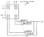
さらに図7を参照して、本発明の一実施例に従って合成電圧ビームパターンを生成するために用いられるシェーピング(ビーム成形)方法について説明する。移動端末130、140、および150について、それぞれ、方位角方向θ1、θ2、およびθ3、ならびに正規化適正受信電圧V1、V2、およびV3を決定する。正規化適正受信電圧および方位角方向は、任意の方法で決定することができる。例えば、方位角方向を移動端末の位置から決定し、適正受信電圧を、移動端末から受信される誤り情報ビットのようなパワー制御情報あるいは信号品質情報のいずれかから決定した後に、正規化することができる。図9a、図9b、および図9cはそれぞれ、基地局112と、移動端末130、140、および150のうちの1つとを含むセクタ102aを示す。それぞれの移動端末130、140、および150はそれぞれ、その移動端末の方位角方向および正規化適正受信電圧を用いて生成可能な対応する電圧ビームパターン135、145、および155を有する。
【0038】
正規化適正受信電圧および方位角方向を決定した後、移動端末のうちの1つ(例えば、移動端末130)に関する電圧ビームパターンを決定する。フェーズドアレーアンテナを用いて1つの移動端末へ信号を送信するビームパターンを形成する方法は周知であり、アンテナに関する文献、例えば、JOSEPH C. LIBERTI, JR and THEODORE S. RAPPAPORT, "SMART ANTENNAS FOR WIRELESS COMMUNICATIONS: IS-95 AND THIRD GENERATION CDMA APPLICATIONS", Prentice Hall PTR (1999)、に記載されている。フェーズドアレーアンテナを用いて1つの移動端末へ信号を送信するビームパターンを形成することについては、この文献の83〜88ページに記載されている。
【0039】
図10からわかるように、電圧ビームパターン135は、方位角方向θ1、すなわち、移動端末130の方位角方向に正規化適正受信電圧V1を提供するように、成形される。電圧ビームパターン135はまた、方位角方向θ2、すなわち、移動端末140の方位角方向にも、ある電圧V1′を提供する。図9bに示したように、移動端末140が信号を受信することを必要とする唯一の移動端末であると仮定した場合、フェーズドアレーアンテナ225は、移動端末140が信号を許容される程度で受信するために、方位角方向θ2にV2ボルトを提供する電圧ビームパターンを生成することが必要となる。しかし、図10からわかるように、電圧ビームパターン135はすでに、方位角方向θ2に、ある電圧を提供している。そこで、電圧ビームパターン145は、方位角方向θ2にV2−V1′ボルトの電圧を提供するように決定される(これを、決定された電圧ビームパターン145′という)。図11に、フェーズドアレーアンテナ225によって生成される、電圧ビームパターン135および145′を示す。
【0040】
図9cに示したように、移動端末150が信号を受信することを必要とする唯一の移動端末であると仮定した場合、フェーズドアレーアンテナ225は、移動端末150が信号を許容される程度で受信するために、方位角方向θ3にV3ボルトを提供する電圧ビームパターンを生成することが必要となる。しかし、図11からわかるように、電圧ビームパターン135および145′はすでに、方位角方向θ3に、ある電圧V1″およびV2′をそれぞれ提供している。そこで、電圧ビームパターン155は、方位角方向θ3にV3−V2′−V1″ボルトの電圧を提供するように決定される(これを、決定された電圧ビームパターン155′という)。図12に、フェーズドアレーアンテナ225によって生成される、電圧ビームパターン135、145′、および155′を示す。
【0041】
図12からわかるように、決定された電圧ビームパターン145′および155′は、方位角方向θ1に、それぞれV2″およびV3′ボルトを提供する。したがって、電圧ビームパターン135は、決定された電圧ビームパターン145′および155′によって方位角方向θ1に提供される電圧を考慮に入れて、再び決定される。電圧ビームパターン135を決定すると、決定された電圧ビームパターン135′が得られる。
【0042】
電圧ビームパターン135を決定して、決定された電圧ビームパターン135′が得られると、それが方位角方向θ2に提供する電圧の値V1′が変化する。さらに、電圧ビームパターン155′は、方位角方向θ2にV3″ボルトを提供する。したがって、今度は、決定された電圧ビームパターン155′および135′を考慮に入れて、電圧ビームパターン145′を再び決定しなければならない。電圧ビームパターン145′のこの決定は、それが方位角方向θ1およびθ3に提供している電圧の値を変化させる。決定された電圧ビームパターン135′および145′が再び決定されているため、新たに決定された電圧ビームパターン135′および145′を考慮に入れて、決定された電圧ビームパターン155′を再び決定しなければならない。
【0043】
3個の電圧ビームパターンを決定するこのプロセスは、3個の電圧ビームパターンのそれぞれが収束するまで繰り返される。電圧ビームパターンが収束するのは、決定された電圧ビームパターンと、前の反復の決定された電圧ビームパターンとの間の変化が小さいときである。これがいつ起こるかを計算するため、まず、決定された電圧ビームパターンから形成されることになる合成電圧ビームパターンを決定する。合成ビームパターンのパワーを計算し、最後の反復の電圧ビームパターンから形成される合成ビームパターンのパワーと比較する。例えば、合成ビームパターンのパワーが、最後の反復の電圧ビームパターンから形成される合成ビームパターンのパワーの1%の誤差の範囲内にあるときに、電圧ビームパターンは収束したとみなすことができる。
【0044】
このシェーピング方法の代替実施例では、移動端末の方位角方向に向かうエネルギーの量は次のように求められる。まず、それぞれの移動端末について、その移動端末が信号を受信することを必要とする唯一の移動端末であると仮定した場合に、その移動端末における許容受信強度を提供するために生成しなければならない電磁場を決定する。次に、これらの電磁場を用いてスケーリングファクタを決定する。これは、以下で説明するように、少なくとも2つの移動端末について決定された電磁場が、これらの2つの移動端末のそれぞれについて適正受信強度に実質的に等しい電磁場強度を提供するように、それぞれの電磁場をスケーリングする係数である。
【0045】
したがって、このシェーピング方法は、結果として得られる合成電圧ビームパターンが、移動端末130、140、および150のうちの少なくとも2つの移動端末のいずれの位置においても、正規化適正受信電圧と少なくとも同程度(ただし、それより実質的に大きくはない)となる電圧を有するように、電圧ビームパターン135、145、および155を決定し結合する。これは、システム資源を節約し、他の信号との干渉を低減し、同時に送信可能な信号の数を増大させるため、容量を増大させ、したがって、収益を増大させる。
【0046】
シェーピング方法の数学的説明
図13に、フェーズドアレーアンテナ225を詳細に示す。フェーズドアレーアンテナ225は、M×N個のアンテナ素子のアレイを有する。フェーズドアレーアンテナ225は、アンテナ素子の列もしくは行またはその両方を用いて、生成された電磁場を、したがって電圧ビームパターンを成形して向きづける。例えば、フェーズドアレーアンテナ225は、アンテナ素子のM個の列を用いて、1つの方向(例えば方位角方向)に電圧ビームパターンを成形し向きづけることができる。フェーズドアレーアンテナ225はまた、アンテナ素子のN個の行を用いて、別の方向(例えば仰角方向)に電圧ビームパターンを成形し向きづけることができる。
【0047】
図7と図13を同時に参照して、フェーズドアレーアンテナ225が、移動端末130において正規化適正受信電圧を生成するビームパターンを生成する方法について説明する。前述のように、送信器522は、移動端末130に対する方位角方向θ1および正規化適正受信電圧V1を求める。
【0048】
フェーズドアレーアンテナ225は、アンテナ素子のそれぞれの列に対応する重みW1(sinθ1),...,W(sinθ1)を有する。それぞれの重みW1(sinθ1),...,W(sinθ1)は、式(1)で示されるような振幅および重みを有する。
【数1】

【0049】
フェーズドアレーアンテナ225は、電圧V11と、重みW1(sinθ1),...,W(sinθ1)を用いて、ビームパターン135を生成する。当業者に周知のように、V11は、フェーズドアレーアンテナ225が、移動端末130が信号を許容される程度で受信することを保証するためにのみ電圧ビームパターンを生成しなければならないと仮定した場合に、正規化適正受信電圧V1を誘起するためにフェーズドアレーアンテナ225によって使用されることが可能な電圧である。フェーズドアレーアンテナ225は、アンテナ素子のそれぞれの列に対して、電圧V11と、その列に対応する重みW1(sinθ1),...,W(sinθ1)との積を提供する。重みW1(sinθ1),...,W(sinθ1)は、式2に示すような重みベクトルZ1を構成する。
Z1=[W1(sinθ1),W2(sinθ1),...,W(sinθ1)]の転置 (2)
【0050】
電圧ビームパターン135は、V1f(u−u1)と表すことができる。ただし、uはsin(θ)であり、u1はsin(θ1)であり、
【数2】
【0051】
u方向におけるビームパターン135の電圧は、F1(u)と表すことができる。すなわち、F1(u)=V1f(u−u1)である。
【0052】
こうして、フェーズドアレーアンテナ225は、重みベクトルと電圧を用いて電圧ビームパターンを生成する。したがって、それぞれの電圧ビームパターン135、145、および155に対応する重みベクトルZ1、Z2、およびZ3がある。上記のシェーピング方法に従って電圧ビームパターンを決定するため、重みベクトルZ1、Z2、Z3のそれぞれに、スケーリングファクタC1、C2、C3をそれぞれ乗じる。次に、スケーリングされた重みベクトルを結合して、合成ビームパターン175の合成重みベクトルZ5を求める。したがって、合成重みベクトルZ5は式(4)で与えられる。
Z5=C1Z1+C2Z2+C3Z3 (4)
【0053】
上記のシェーピング方法に基づいて、スケーリングファクタC1、C2、およびC3を決定する1つの方法について説明する。
【0054】
方位角方向θxにおける合成ビームパターン175の電圧F5(ux)は、方位角方向θx(すなわち、特定の移動端末の方位角方向)におけるビームパターン135、145、および155の部分に、対応するスケーリングファクタC1、C2、C3を乗じたものの和である。すなわち、方位角方向θxにおける電圧の値F5(ux)は、式5に示すとおりである。
F5(ux)=[C1f(ux−u1)+C2f(ux−u2)+C3f(ux−u3)] (5)
【0055】
ただし、
xは、移動端末130に対して1、移動端末140に対して2、移動端末150に対して3であり、
C1f(ux−u1)は、方位角方向θxにおける電圧ビームパターン135の部分であり、
C2f(ux−u2)は、方位角方向θxにおける電圧ビームパターン145の部分であり、
C3f(ux−u3)は、方位角方向θxにおける電圧ビームパターン155の部分であり、
uxは、sin(θx)であり、
u1は、sin(θ1)であり、
u2は、sin(θ2)であり、
u3は、sin(θ3)である。
【0056】
3つの方位角方向θ1、θ2、およびθ3のそれぞれにおける合成電圧ビームパターン175の電圧は、式(5)を用いて計算することができる。
【0057】
方位角方向θ1における合成電圧ビームパターン175の電圧F5(u1)は、式6で与えられる。
F5(u1)=[C1+C2f(u1−u2)+C3f(u1−u3)] (6)
方位角方向θ2における合成電圧ビームパターン175の電圧F5(u2)は、式7で与えられる。
F5(u2)=[C1f(u2−u1)+C2+C3f(u2−u3)] (7)
方位角方向θ3における合成電圧ビームパターン175の電圧F5(u3)は、式8で与えられる。
F5(u3)=[C1f(u3−u1)+C2f(u3−u2)+C3] (8)
【0058】
合成電圧ビームパターン175は、方位角方向θxにおいて少なくとも正規化適正受信電圧を提供しなければならない。したがって、方位角方向θxにおける電圧F5(ux)の大きさは、方位角方向θxにおいて必要とされる正規化適正受信電圧Vx以上でなければならない。
|F5(ux)|≧Vx (9)
3つの移動端末に対する値をxに代入すると、式9から次の3つの不等式が導かれる。
|[C1+C2f(u1−u2)+C3f(u1−u3)]|≧V1 (10)
|[C1f(u2−u1)+C2+C3f(u2−u3)]|≧V2 (11)
|[C1f(u3−u1)+C2f(u3−u2)+C3]|≧V3 (12)
不等式10において絶対値をはずしてC1について解くと、次式が得られる。
C1≧V1−[C2f(u1−u2)+C3f(u1−u3)] (13)
または C1≦−V1−[C2f(u1−u2)+C3f(u1−u3)] (14)
【0059】
しかし、方位角方向θ1における決定された電圧ビームパターン145′および155′の部分の和、すなわち、[C2f(u1−u2)+C3f(u1−u3)]が、正規化適正受信電圧V1より大きい場合、決定された電圧ビームパターン135′は不要であるため、C1は0とおくことができる。したがって、不等式13および14は次のようになる。
C1=max(0,V1−[C2f(u1−u2)+C3f(u1−u3)]) (15)
または C1=min(0,−V1−[C2f(u1−u2)+C3f(u1−u3)]) (16)
同様に、不等式11は次のようになる。
C2=max(0,V2−[C1f(u2−u1)+C3f(u2−u3)]) (17)
または C2=min(0,−V2−[C1f(u2−u1)+C3f(u2−u3)]) (18)
同様に、不等式12は次のようになる。
C3=max(0,V3−[C1f(u3−u1)+C2f(u3−u2)]) (19)
または C3=min(0,−V3−[C1f(u3−u1)+C2f(u3−u2)]) (20)
【0060】
それぞれのスケーリングファクタについて2つの選択肢があるため(C1について式15または16、C2について式17または18、C3について式19または20)、スケーリングファクタの組合せは8通りある。なお、C1は、式15では0以上であり、式16では0以下である。C2は、式17では0以上であり、式18では0以下である。C3は、式19では0以上であり、式20では0以下である。記載を簡単にするため、まず、式15、17、および19の結果として、すべてのスケーリングファクタC1、C2、およびC3から得られるスケーリングファクタの組合せが正である場合のシェーピング方法について説明する。
【0061】
正規化適正受信電圧V1、V2、およびV3、ならびに、方位角方向θ1、θ2、およびθ3を決定した後、電圧ビームパターンのうちの1つ(例えば135)を、あたかも移動端末130(これは、この電圧ビームパターンに対応する)が信号を受信することを必要とする唯一の移動端末であるかのように、生成する。これを生成するために、C2およびC3を0とおく。式15においてC2およびC3を0とおくと、C1はV1に等しくなる。
【0062】
次に、方位角方向θ2における電圧ビームパターン135の部分、すなわち、C1f(u2−u1)を用いて、決定された電圧ビームパターン145′を計算する。ビームパターン145′を生成するため、C1を、今得られたC1の値とし(すなわち、C1=V1)、C3を0とおく。式17においてC1=V1かつC3=0とおいて、C2を計算する。この計算されたC2をC2′ということにする。
【0063】
次に、方位角方向θ3における電圧ビームパターン135および145′の部分、すなわち、C1f(u3−u1)およびC2f(u3−u2)を用いて、決定された電圧ビームパターン155′を計算する。決定された電圧ビームパターン155′を生成するため、C1およびC2を、今得られたC1およびC2の値とし(すなわち、C1=V1かつC2=C2′)とする。式19においてC1=V1かつC2=C2′とおいて、C3を計算し、これをC3′ということにする。
【0064】
ここで、決定された電圧ビームパターン145′および155′は、方位角方向θ1に電圧を提供する可能性がある。したがって、今得られたC2およびC3の値を用いてC1を再計算して、決定された電圧ビームパターン135′を求めなければならない。
【0065】
C1を再計算すると、方位角方向θ2における決定された電圧ビームパターン135′の部分が変化することになる。さらに、決定された電圧ビームパターン155′が、方位角方向θ2に、ある電圧を提供している。したがって次に、今得られたC1およびC3の値を用いてC2を再計算しなければならない。
【0066】
C1およびC2を再計算すると、方位角方向θ3における決定された電圧ビームパターン135′および145′の部分が変化することになる。したがって次に、今得られたC1およびC2の値を用いてC3を再計算しなければならない。
【0067】
スケーリングファクタC1、C2、およびC3を反復して再計算するこのプロセスは、3つのスケーリングファクタのそれぞれが収束するまで継続しなければならない。スケーリングファクタが収束するのは、再計算されたスケーリングファクタと、前の反復のスケーリングファクタとの間の変化が小さいときである。
例えば、スケーリングファクタを用いて決定される合成電圧ビームパターンの全パワーが、前の反復のスケーリングファクタを用いて決定される合成電圧ビームパターンの全パワーの1%の誤差の範囲内にあるときに、スケーリングファクタは収束したとみなすことができる。
【0068】
式15、16、17、18、19および20に戻ると、それぞれのスケーリングファクタについて2つの選択肢がある。すなわち、各スケーリングファクタC1、C2、およびC3は、式15、17、および19を解くことによってそれぞれ0以上となる可能性があり、また、各スケーリングファクタC1、C2、およびC3は、式16、18、および20を解くことによってそれぞれ0以下となる可能性がある。各スケーリングファクタについて2つの方程式があるため、方程式の組合せは8通りあり、これはスケーリングファクタの8通りの組合せを生じる。
【0069】
【表1】
今説明したシェーピング方法は、組合せ1についてのものである。好ましい実施例では、前半の4つまたは後半の4つのいずれかの組合せが選択される。この4つの組合せのそれぞれを用いて、組合せ1について前述したのと同様にして、スケーリングファクタのセットを計算する。次に、それぞれのスケーリングファクタのセットを用いて、合成ビームパターンを生成する。次に、合成ビームパターンのパワーを計算する。最小パワーの合成ビームパターンを、図5に示した合成ビームパターン175として選択すべきである。プロセッサ523は、スケーリングファクタの組合せを計算するために使用可能である。
【0071】
次に、4つの組合せのみを使用する理由について説明する。組合せ1は、組合せ8によって生成されるスケーリングファクタと大きさが等しく逆符号のスケーリングファクタのセットを生成する。これらの2つのスケーリングファクタのセットは等しい大きさおよび逆符号を有するため、重みベクトルZ1、Z2およびZ3の和の大きさをこれらのスケーリングファクタの一方のセットによってスケーリングしたものは、重みベクトルZ1、Z2およびZ3の和の大きさを他方のスケーリングファクタのセットによってスケーリングしたものと等しくなる。パワーを求めるためにこれらの2つの和を2乗すると、2つの和の2乗は相等しくなる。したがって、組合せ1および8によって生成されるスケーリングファクタは、等しいパワーを有する電圧ビームパターンを生成するので、どの合成電圧ビームパターンが最小パワーとなるかを考慮する際には、これらのスケーリングファクタのセットのうちの一方のセットのみで十分である。
【0072】
同様に、組合せ2は、組合せ7によって生成されるスケーリングファクタと大きさが等しく逆符号のスケーリングファクタのセットを生成する。したがって、上記で説明したように、どの合成電圧ビームパターンが最小パワーとなるかを考慮する際には、これらのスケーリングファクタのセットのうちの一方のセットのみを用いれば十分である。同様に、組合せ3は、組合せ6によって生成されるスケーリングファクタと大きさが等しく逆符号のスケーリングファクタのセットを生成し、組合せ4は、組合せ5によって生成されるスケーリングファクタと大きさが等しく逆符号のスケーリングファクタのセットを生成する。
【0073】
今説明したステップの系列は、スケーリングファクタC1、C2、およびC3を決定する1つの方法である。次に、上記の本発明の代替実施例に従ってスケーリングファクタを決定する別の方法について説明する。解析を容易にするため、2個の移動端末の場合についてこの説明を行う。2個の移動端末があるとき、式15〜18は次のようになる。
C1=max(0,V1−[C2f(u1−u2)]) (21)
または C1=min(0,−V1−[C2f(u1−u2)]) (22)
同様に、式14は次のようになる。
C2=max(0,V2−[C1f(u2−u1)]) (23)
または C2=min(0,−V2−[C1f(u2−u1)]) (24)
【0074】
f(u)は偶関数であるため、f(u1−u2)=f(u2−u1)である。
したがって、2個のスケーリングファクタのそれぞれについて、2つの式、すなわち、C1について21または22、また、C2について23または24、のいずれを選択するかを決定した後には、2変数C1およびC2に関する2つの方程式があり、これらはC1およびC2について解くことができる。使用すべき方程式の選択は、2つの移動端末への2つの電磁場どうしの干渉のタイプおよび量に基づく。干渉のタイプおよび量は、f(u1−u2)の大きさから決定することができる。
【0075】
0≦f(u1−u2)≦V2/V1のとき、式21および23が用いられ、したがって、
C1=V1−C2f(u1−u2)、かつ、C2=V2−C1f(u1−u2)
である。これらの2つの方程式をC1およびC2について解くと、次のようになる。
【数3】
V2/V1≦f(u1−u2)≦1のとき、C1=V1、かつ、C2=0である。
【0077】
−V2/V1≦f(u1−u2)≦0のとき、式21および24が用いられ、したがって、
C1=V1−C2f(u1−u2)、かつ、C2=−V2−C1f(u1−u2)
である。これらの2つの方程式をC1およびC2について解くと、次のようになる。
【数4】
f(u1−u2)≦−V2/V1のときは、C1=V1、かつ、C2=0である。
【0079】
ヌル充填ファクタ
さらに、好ましい実施例では、合成重みベクトルZ5をさらにロバストにすることにより、ビームパターンをさらにロバストにすることができる。式2に示したように、重みベクトルは、アンテナ素子のそれぞれの列に関する重みの転置であり、また、式4に記載したように、合成重みベクトルは、個々の電圧ビームパターンのスケーリングされた重みベクトルの和である。式2および4と、アンテナ素子のそれぞれの列に関する重みZ51,...,Z5Mとを用いると、合成重みベクトルを次のように決定することができる。
Z5=[Z51,...,Z5M]の転置 (25)
【0080】
前述のように、シェーピング方法に従って、電圧ビームパターン135、145、155のうちの1つが生成される。図14に、デカルト座標系でプロットした合成電圧ビームパターン135を示す。図14からわかるように、電圧ビームパターンのうちの1つ(例えば、電圧ビームパターン135)が生成されると、この電圧ビームパターンは、大きい中心ローブ910と、それより小さいサイドローブ920および930とを有し、これらのローブの間にヌル領域940および950がある。中心ローブ910は、移動端末130へと成形され向けられている。第2の移動端末(例えば、移動端末140)が、ビームパターン135の中心ローブまたはサイドローブのうちの1つにある場合、合成ビームパターン175は、第2の移動端末が信号を許容される程度で受信するために方位角方向θ2に追加電圧を必要としないため、スケーリングファクタC2は0とおかれる。したがって、決定された電圧ビームパターン145′は0となり、合成ビームパターン175は、C2を0とおいて計算される。
【0081】
しかし、移動端末140がローブの端に近い場合、これは問題を生じることがある。移動端末140がヌル領域のうちの1つ(例えば、ヌル領域950)に位置する場合、移動端末140の方位角方向を求めるときにわずかな誤差があっても、システムは、移動端末140が、ローブのうちの1つ(この場合には、ローブ920)のパターン内に位置すると判定する可能性がある。したがって、信号が実際には移動端末140によって許容される程度で受信されていないときでも、送信器は、フェーズドアレーアンテナが、移動端末140によって許容される程度で受信される信号を伝える合成電圧ビームパターンを生成していると判定する可能性がある。
【0082】
方位角方向推定誤差に対して、よりロバストな合成ビームパターンを形成するため、重みベクトルZ5にヌル充填ファクタηを付加して重みベクトルZ6を生成する。式25にヌル充填ファクタηを付加すると式26が得られる。
【数5】
【0083】
以上は単なる例示である。したがって、例えば、実施例では、本発明の方法について、3個の移動端末の場合を説明したが、代替実施例として、本発明の方法は、2個以上の任意の個数の移動端末の場合にも使用可能である。
【0084】
さらに、実施例では、電圧ビームパターンは、正規化電圧を用いて生成される。代替実施例では、電圧ビームパターンは、電圧を正規化せずに生成することも可能である。この場合、それぞれの電圧ビームパターンは、フェーズドアレーアンテナからの相異なる距離に誘起される電圧を用いて決定される。これは、ある移動端末の位置に、別の移動端末へ向かう電圧ビームパターンによって提供される電圧の大きさを計算するときに、考慮に入れなければならない。例えば、第1の電圧ビームパターン(第1の移動端末に対応する)が第2の方位角方向(第2の移動端末の方位角方向)に提供する電圧の大きさは、第1の電圧ビームパターンに対応する電磁場によって第2の方位角方向においてフェーズドアレーアンテナから第2の移動端末までの距離に誘起される電圧の大きさとなる。
【0085】
さらに、実施例では、電圧の大きさはr=30メートルに正規化されるが、代替実施例では、rは任意の距離とすることが可能であり、その場合、電圧の大きさは、フェーズドアレーアンテナからのその距離に誘起される電圧に正規化されることになる。
【0086】
さらに、当業者には認識されるように、実施例では、各セルは3個の120°セクタに分割されるが、セルは、許容される任意のサイズの、任意の個数のセクタに分割することが可能である。また、セルは、全方位セクタとすることが可能であり、その場合、各セルは1個の360°セクタを有する。
【0087】
さらに、実施例では、プロセッサ523は、図5において、送信器522に配置されるように示されているが、本発明の代替実施例では、プロセッサ523は、ワイヤレス通信システムの任意の位置(例えば、基地局112の別の部分や、MSC)に配置することが可能である。
【0088】
さらに、実施例では、本発明は、特定の方位角方向に集束した電磁場を用いて実行されるが、代替実施例では、本発明は、別の方向(例えば、仰角方向)に集束した電磁場を用いて実施することも可能である。
【0089】
特許請求の範囲の発明の要件の後に括弧で記載した番号は、本発明の一実施例の対応関係を示すもので本発明の範囲を限定するものと解釈すべきではない。
【図面の簡単な説明】
【図1】ワイヤレス通信システムの一部のブロック図である。
【図2】図2aは、図1のワイヤレス通信システムのセクタを示す図である。このセクタは、信号を1つの移動端末に送信するフェーズドアレーアンテナを有する基地局を含む。図2bは、ワイヤレス通信システムのセクタを示す図である。このセクタは、信号を1つの移動端末に送信する非フェーズドアレーアンテナを有する基地局を含む。
【図3】ワイヤレス通信システムのセクタを示す図である。このセクタは、フェーズドアレーアンテナを有する基地局を含む。また、この図は、移動端末が信号を許容される程度で受信するために、これらの移動端末の位置で誘起されることが必要となる電圧の大きさを示す。
【図4】弱め合う干渉の結果として、図3の移動端末の位置で誘起される電圧を示す図である。
【図5】図1のワイヤレス通信システムのセクタを示す図である。このセクタは、フェーズドアレーアンテナを有する基地局を含む。また、この図は、移動端末が信号を許容される程度で受信するために、これらの移動端末の位置で誘起される電圧の大きさを示す。
【図6】図6aは、図2aの電磁場を表す電圧ビームパターンのデカルト座標系におけるプロットを示す図である。図6bは、図2aの電磁場を表す電圧ビームパターンの極座標系におけるプロットを示す図である。
【図7】図5のフェーズドアレーアンテナによって生成される電圧ビームパターンを示す図である。
【図8】図5の電圧を正規化したものを示す図である。
【図9】図9a、図9b、および図9cは、移動端末のうちの1つのみに信号を送信するために図5のフェーズドアレーアンテナによって生成される電圧ビームパターンを示す図である。
【図10】第1の移動端末に信号を送信する図5のフェーズドアレーアンテナによって生成される電圧ビームパターンを示すとともに、第2の移動端末にその信号を送信するのに必要とされる追加ビームパターンを示す図である。
【図11】第1の移動端末に信号を送信する図5のフェーズドアレーアンテナによって生成される電圧ビームパターンと、第2の移動端末にその信号を送信するのに必要とされる追加ビームパターンと、第3の移動端末にその信号を送信するのに必要とされる追加ビームパターンとを示す図である。
【図12】図11の3個のビームパターンを送信する図5のフェーズドアレーアンテナを示す図である。
【図13】フェーズドアレーアンテナのブロック図である。
【図14】重みベクトルを用いて生成される合成電圧ビームパターンと、重みベクトルおよびヌル充填ファクタを用いて生成される合成電圧ビームパターンとを示す図である。
【符号の説明】
100 ワイヤレス通信システム
102,104,106 セル
102a〜102c,104a〜104c,106a〜106c セクタ
112,114,116 基地局
118 移動通信交換センタ(MSC)
119 ネットワーク
120,130,140,150 移動端末
135,145,155 電圧ビームパターン
175,185 合成電圧ビームパターン
201 ブロードサイド
204a セクタ
214 基地局
224 送信器
225 フェーズドアレーアンテナ
228 送信器
229 非フェーズドアレーアンテナ
302 セクタ
322 送信器
330,340,350 移動端末
522 送信器
523 プロセッサ
910 中心ローブ
920,930 サイドローブ
940,950 ヌル領域[0001]
BACKGROUND OF THE INVENTION
The present invention relates to communication systems, and more particularly to wireless communication systems.
[0002]
[Prior art]
The transmitter uses an antenna to transmit the signal to the receiver. For example, transmitters in so-called base stations of wireless communication systems use antennas to transmit signals to mobile terminals. The antenna radiates energy and generates an electromagnetic field (EM field) that transmits the signal to the mobile terminal. In particular, phased array antennas generally generate a focused electromagnetic field from the electromagnetic field generated by non-phased array antennas. “A more focused electromagnetic field” means that (1) the maximum energy is directed to a specific azimuth direction (for example, the azimuth direction of a mobile terminal to which a signal is transmitted) and (2) the angle from the azimuth direction As this increases, this field strength means an electromagnetic field that falls more sharply than the intensity of an unfocused field, such as that generated by a non-phased array antenna. The azimuth direction is the angle of the mobile terminal from the broad side (vertical plane perpendicular to the front surface) of the phased array antenna. Although electromagnetic energy is actually directed to a specific azimuthal direction, in this specification, for the sake of simplicity, the electromagnetic field is directed to the azimuthal direction where the maximum energy is directed.
[0003]
The electromagnetic field generated by the phased array antenna is more focused than the electromagnetic field generated by the non-phased array antenna (sometimes known to those skilled in the art as “narrower”) and is therefore directed to a particular mobile terminal by the phased array antenna The signal carried by the electromagnetic field is less likely to interfere with the signal to other mobile terminals in the same (or different) so-called sector of the cell of the wireless communication system than the signal carried by the electromagnetic field generated by the non-phased array antenna. . As a result, the number of mobile terminals in the wireless communication system can be increased, and thus the capacity of the wireless communication system can be increased. (The capacity of a wireless communication system is the number of calls that can be transmitted simultaneously by the wireless communication system.)
[0004]
The phased array antenna must generate an electromagnetic field such that an acceptable received voltage (voltage received by the mobile terminal) is induced at the location of the mobile terminal. The allowable reception voltage is a voltage necessary for the mobile terminal to receive a signal with an allowable level of signal performance. Power control information or signal quality information such as error information bits received from the mobile terminal is usually used at the base station to adjust the electromagnetic field so that an acceptable received voltage is induced at the mobile terminal location. .
[0005]
In a normal wireless communication system, signals transmitted to a plurality of mobile terminals are all transmitted at the same frequency. (For example, in a so-called TDMA wireless communication system, signals to three mobile terminals are transmitted at the same frequency.) When signals are transmitted to a plurality of mobile terminals at the same frequency using a phased array antenna, the plurality of mobile terminals are transmitted. It can cause destructive interference of the electromagnetic field towards the terminal. When the electromagnetic field directed to the first mobile terminal induces a secondary voltage at the position of the second mobile terminal, and this secondary voltage is out of phase with the primary voltage induced by the electromagnetic field directed to the second mobile terminal , Destructive interference occurs. In this case, the secondary voltage reduces the magnitude of the primary voltage. This reduction in magnitude may be so great that the second mobile terminal cannot receive an acceptable received voltage and therefore cannot receive a signal with an acceptable level of signal quality.
[0006]
[Problems to be solved by the invention]
It has been proposed to minimize problems due to destructive interference by using a focused electromagnetic field with alternating orthogonal polarizations, each electromagnetic field going in a certain direction. The voltage induced at the location of the mobile terminal is induced by both the electromagnetic field in the direction closest to the direction of the mobile terminal and all other electromagnetic fields. However, because adjacent electromagnetic fields have orthogonal polarizations, the possibility of destructive interference is reduced. This reduces the likelihood that one of the mobile terminals will not receive the signal to an acceptable degree (receive a signal with an acceptable level of signal performance).
[0007]
While the above approach reduces the likelihood that one of the mobile terminals will not receive the signal to an acceptable extent, the inventors of the present invention have recognized that further improvements are possible. Specifically, the inventors of the present invention have recognized that the same frequency electromagnetic field (EM field) towards multiple mobile terminals not only has destructive interference at any location across the sector, The prior art does not use the fact that there is also constructive interference. When the electromagnetic field toward the first mobile terminal induces a secondary voltage at the position of the second mobile terminal, and this secondary voltage is in phase with the primary voltage induced by the electromagnetic field toward the second mobile terminal, Intensifying interference occurs. In this case, the magnitudes of the two voltages induced at the position of the second mobile terminal are added together. In such a case, a smaller amount of energy is induced at the second mobile terminal by the energy towards the second mobile terminal than if the secondary voltage is not induced. Thereby, system resources can be used more efficiently.
[0008]
[Means for Solving the Problems]
According to the present invention, energy is directed in multiple directions (eg, azimuthal directions). The amount of energy toward the azimuthal direction of a terminal (eg, mobile terminal) is a function of the position of the at least two mobile terminals and the acceptable reception strength. However, the allowable reception strength of a mobile terminal is the strength of the electromagnetic field necessary for the mobile terminal to receive a signal with an acceptable level of signal performance. This function is such that the strength of the electromagnetic field at any of these at least two mobile terminals is at least as great as that required for the mobile terminal to receive the signal transmitted by the electromagnetic field to an acceptable extent (but Is not substantially larger than that).
[0009]
In an alternative embodiment of the present invention, the amount of energy going in the azimuth direction of the mobile terminal is determined as follows. First, for each mobile terminal, the electromagnetic field that must be generated to provide the acceptable reception strength at that mobile terminal is determined. This determination takes into account the strength of the electromagnetic field already determined for other mobile terminals at the position of the mobile terminal. This determination is repeated until the electromagnetic field determined for at least two mobile terminals provides an electromagnetic field strength that is substantially equal to the proper received strength for each of these at least two mobile terminals. However, the proper reception strength is a substantially minimum allowable reception strength.
[0010]
The determination step is repeated until the electromagnetic field converges. This convergence is achieved when the change between the determined electromagnetic field and the determined electromagnetic field of the previous iteration is small. Thereafter, the amount of energy toward the azimuth direction of each terminal is determined based on the electromagnetic field thus determined.
[0011]
After the electromagnetic field has converged, the resultant electromagnetic field thus obtained is actually, as described above, the strength at any position of these at least two mobile terminals allowing the mobile terminal to accept the signal carried by the composite electromagnetic field. An electromagnetic field that is at least as strong as (but not substantially greater than) the strength required to receive it. This saves system resources, reduces interference with other signals, and simultaneously increases the number of signals that can be transmitted, thus increasing capacity and thus increasing the profitability of the wireless communication system.
[0012]
DETAILED DESCRIPTION OF THE INVENTION
In FIG. 1, the geographic area served by the wireless communication system 100 is divided into a plurality of spatially separated areas called “cells”. To facilitate analysis, each
[0013]
FIG. 2a shows the sector 104a in detail. The transmitter 224 in the
[0014]
The phased
[0015]
FIG. 2 b shows a sector 204 a such that transmitter 228 in base station 214 transmits signals to
[0016]
The electromagnetic field generated by the phased
[0017]
FIG. 3 shows a
[0018]
Sending signals to these three
[0019]
It has been proposed to minimize problems due to destructive interference by using a focused electromagnetic field with alternating orthogonal polarizations, each electromagnetic field going in a certain direction. The voltage induced at the location of the mobile terminal is induced by both the electromagnetic field in the direction closest to the direction of the mobile terminal and all other electromagnetic fields. However, because adjacent electromagnetic fields have orthogonal polarizations, the possibility of destructive interference is reduced. This reduces the likelihood that one of the mobile terminals will not receive the signal to an acceptable degree (receive a signal with an acceptable level of signal performance).
[0020]
While the above approach reduces the likelihood that one of the mobile terminals will not receive the signal to an acceptable extent, the inventors of the present invention have recognized that further improvements are possible. Specifically, the inventors of the present invention have recognized that an electromagnetic field of the same frequency directed to a plurality of mobile terminals not only causes destructive interference at any position throughout the sector, but also constructs interference. The prior art does not use the fact that
[0021]
The constructive interference will be described with reference to FIG. FIG. 5 shows the
[0022]
When the electromagnetic field towards the
[0023]
In accordance with the present invention,
[0024]
(Note: The strength of the electromagnetic field at either position of these two mobile terminals is not substantially greater than the strength required for that mobile terminal to receive the signals carried by that field to an acceptable extent. Assuming that the strength is substantially greater than the strength required for the mobile terminal to receive the signal to an acceptable extent, the amount of energy generated in the azimuth direction of the mobile terminal, and hence the power, is It becomes substantially larger than the amount needed to transmit a signal to the mobile terminal, using substantially more power than necessary wastes system resources and causes interference with other signals, (Reducing the number of signals that can be transmitted simultaneously, which causes a loss of capacity and hence a loss of revenue.)
[0025]
In an embodiment of the present invention, several steps are performed to determine the amount of energy to be directed in the azimuthal direction of each mobile terminal. In performing these steps, the
[0026]
In performing the above steps, the
[0027]
One exemplary method for determining when the electromagnetic field converges is as follows. First, a synthetic electromagnetic field to be formed from the determined electromagnetic field is determined. Next, a so-called combined beam pattern corresponding to the combined electromagnetic field is obtained (details will be described later). The power of the composite beam pattern is calculated and compared with the composite beam pattern corresponding to the composite electromagnetic field of the last iteration. For example, an electromagnetic field can be considered converged when the power of the combined beam pattern corresponding to the combined electromagnetic field is within 1% error of the combined beam pattern corresponding to the previous repeated combined electromagnetic field.
[0028]
After the electromagnetic field has converged, the combined electromagnetic field is, as described above, the strength at any position of at least two of the
[0029]
(Note that if an electromagnetic field directed to another mobile terminal induces an acceptable received voltage at the position of the mobile terminal, the electromagnetic field directed to that mobile terminal is determined to be 0. For example, the
[0030]
The strength of the electromagnetic field at a particular location can be expressed as a voltage induced by the electromagnetic field at that location. Thus, the voltage induced by the combined electromagnetic field at any position of at least two of the
[0031]
The strength of the electromagnetic field at a certain radius from the phased array antenna can be represented by a beam pattern such as a voltage beam pattern. Thus, the electromagnetic field can be represented by a beam pattern. Referring again to FIG. 2a, the same constant distance r from the phased
[0032]
In an embodiment of the invention, the composite electromagnetic field is determined by determining a corresponding composite voltage beam pattern. FIG. 7 shows the resultant
[0033]
For ease of analysis, the proper received voltage indicated by
[0034]
Referring again to FIG. 7, one method for determining the combined
[0035]
In performing the above steps, the
[0036]
The voltage beam pattern converges when the change between the determined voltage beam pattern and the determined voltage beam pattern of the previous iteration is small. One exemplary method for determining when this occurs is as follows. First, a combined voltage beam pattern to be formed from the determined voltage beam pattern is determined. The power of the combined beam pattern is calculated and compared with the power of the combined beam pattern formed from the last iteration voltage beam pattern. For example, a voltage beam pattern can be considered converged when the power of the combined beam pattern is within an error of 1% of the power of the combined beam pattern formed from the last iteration voltage beam pattern.
[0037]
With further reference to FIG. 7, a shaping (beamforming) method used to generate a composite voltage beam pattern in accordance with one embodiment of the present invention will be described. For
[0038]
After determining the normalized proper reception voltage and azimuth direction, a voltage beam pattern for one of the mobile terminals (eg, mobile terminal 130) is determined. A method of forming a beam pattern for transmitting a signal to a single mobile terminal using a phased array antenna is well known. For example, JOSEPH C. LIBERTI, JR and THEODORE S. RAPPAPORT, "SMART ANTENNAS FOR WIRELESS COMMUNICATIONS : IS-95 AND THIRD GENERATION CDMA APPLICATIONS ", Prentice Hall PTR (1999). Forming a beam pattern for transmitting a signal to one mobile terminal using a phased array antenna is described on pages 83 to 88 of this document.
[0039]
As can be seen from FIG. 10, the
[0040]
As shown in FIG. 9c, assuming that the
[0041]
As can be seen from FIG. 12, the determined voltage beam patterns 145 'and 155'1And V respectively2″ And V3'Provide bolts. Accordingly, the
[0042]
Once the
[0043]
This process of determining three voltage beam patterns is repeated until each of the three voltage beam patterns converges. The voltage beam pattern converges when the change between the determined voltage beam pattern and the determined voltage beam pattern of the previous iteration is small. In order to calculate when this happens, first the composite voltage beam pattern that will be formed from the determined voltage beam pattern is determined. The power of the combined beam pattern is calculated and compared with the power of the combined beam pattern formed from the last iteration voltage beam pattern. For example, a voltage beam pattern can be considered converged when the power of the combined beam pattern is within an error of 1% of the power of the combined beam pattern formed from the last iteration voltage beam pattern.
[0044]
In an alternative embodiment of this shaping method, the amount of energy going in the azimuth direction of the mobile terminal is determined as follows. First, for each mobile terminal, assuming that the mobile terminal is the only mobile terminal that needs to receive the signal, it must be generated to provide an acceptable reception strength at that mobile terminal. Determine the electromagnetic field. Next, a scaling factor is determined using these electromagnetic fields. This is because, as explained below, the electromagnetic field determined for at least two mobile terminals provides an electromagnetic field strength that is substantially equal to the proper received strength for each of these two mobile terminals. Is a scaling factor.
[0045]
Therefore, this shaping method is such that the resulting combined voltage beam pattern is at least as high as the normalized proper received voltage at any position of at least two of the
[0046]
Mathematical description of shaping methods
FIG. 13 shows the phased
[0047]
With reference to FIG. 7 and FIG. 13 simultaneously, a method in which the phased
[0048]
The phased
[Expression 1]
[0049]
The phased
Z1= [W1(Sinθ1), W2(Sinθ1), ..., W (sinθ1)] Transposition (2)
[0050]
The
[Expression 2]
[0051]
The voltage of the
[0052]
Thus, the phased
Z5= C1Z1+ C2Z2+ C3Z3 (4)
[0053]
Based on the above shaping method, the scaling factor C1, C2And C3One method for determining is described.
[0054]
Azimuth direction θxVoltage F of
F5(Ux) = [C1f (ux-U1) + C2f (ux-U2) + C3f (ux-U3]] (5)
[0055]
However,
x is 1 for
C1f (ux-U1) Is the azimuth direction θxPart of the
C2f (ux-U2) Is the azimuth direction θxPart of the voltage beam pattern 145 at
C3f (ux-U3) Is the azimuth direction θxThe
uxIs sin (θx) And
u1Is sin (θ1) And
u2Is sin (θ2) And
u3Is sin (θ3).
[0056]
Three azimuth directions θ1, Θ2, And θ3The voltage of the combined
[0057]
Azimuth direction θ1The voltage F of the composite
F5(U1) = [C1+ C2f (u1-U2) + C3f (u1-U3]] (6)
Azimuth direction θ2The voltage F of the composite
F5(U2) = [C1f (u2-U1) + C2+ C3f (u2-U3] (7)
Azimuth direction θ3The voltage F of the composite
F5(U3) = [C1f (u3-U1) + C2f (u3-U2) + C3] (8)
[0058]
The resultant
| F5(Ux) | ≧ Vx (9)
Substituting the values for the three mobile terminals into x yields the following three inequalities from Equation 9:
| [C1+ C2f (u1-U2) + C3f (u1-U3]] | ≧ V1 (10)
| [C1f (u2-U1) + C2+ C3f (u2-U3]] | ≧ V2 (11)
| [C1f (u3-U1) + C2f (u3-U2) + C3] ≧≧3 (12)
In
C1≧ V1-[C2f (u1-U2) + C3f (u1-U3]] (13)
Or C1≤ -V1-[C2f (u1-U2) + C3f (u1-U3] (14)
[0059]
However, the azimuth direction θ1Is the sum of the portions of the determined voltage beam patterns 145 ′ and 155 ′, ie, [C2f (u1-U2) + C3f (u1-U3)] Is the normalization appropriate reception voltage V1If it is larger, the determined voltage beam pattern 135 'is unnecessary, so C1Can be set to zero. Therefore, inequalities 13 and 14 are as follows:
C1= Max (0, V1-[C2f (u1-U2) + C3f (u1-U3)]) (15)
Or C1= Min (0, -V1-[C2f (u1-U2) + C3f (u1-U3)]) (16)
Similarly,
C2= Max (0, V2-[C1f (u2-U1) + C3f (u2-U3)]) (17)
Or C2= Min (0, -V2-[C1f (u2-U1) + C3f (u2-U3)]) (18)
Similarly, inequality 12 becomes:
C3= Max (0, V3-[C1f (u3-U1) + C2f (u3-U2)]) (19)
Or C3= Min (0, -V3-[C1f (u3-U1) + C2f (u3-U2)]) (20)
[0060]
Because there are two choices for each scaling factor (C1For
[0061]
Normalized proper reception voltage V1, V2And V3, And azimuth direction θ1, Θ2, And θ3, One of the voltage beam patterns (eg, 135) is the only mobile terminal that needs the mobile terminal 130 (which corresponds to this voltage beam pattern) to receive a signal. Generate as if it were. To generate this, C2And C3Is set to 0. C in
[0062]
Next, the azimuth direction θ2Portion of the
[0063]
Next, the azimuth direction θ3Portions of
[0064]
Here, the determined voltage beam patterns 145 ′ and 155 ′ have an azimuth direction θ1There is a possibility to provide a voltage. Therefore, now obtained C2And C3Using the value of C1Must be recalculated to determine the determined voltage beam pattern 135 '.
[0065]
C1Is recalculated, the azimuth direction θ2The portion of the determined voltage beam pattern 135 'at will change. Furthermore, the determined
[0066]
C1And C2Is recalculated, the azimuth direction θ3The determined voltage beam patterns 135 'and 145' in FIG. Therefore, the next C1And C2Using the value of C3Must be recalculated.
[0067]
Scaling factor C1, C2And C3This process of iteratively recalculating must continue until each of the three scaling factors converges. The scaling factor converges when the change between the recalculated scaling factor and the scaling factor of the previous iteration is small.
For example, when the total power of the combined voltage beam pattern determined using the scaling factor is within an error of 1% of the total power of the combined voltage beam pattern determined using the scaling factor of the previous iteration. The scaling factor can be considered converged.
[0068]
Returning to
[0069]
[Table 1]
The shaping method just described is for
[0071]
Next, the reason for using only four combinations will be described.
[0072]
Similarly,
[0073]
The sequence of steps just described is the scaling factor C1, C2And C3Is one way to determine Next, another method for determining the scaling factor in accordance with the above alternative embodiment of the present invention will be described. For ease of analysis, this description is given for the case of two mobile terminals. When there are two mobile terminals, equations 15-18 are as follows:
C1= Max (0, V1-[C2f (u1-U2)]) (21)
Or C1= Min (0, -V1-[C2f (u1-U2)]) (22)
Similarly, Equation 14 is as follows.
C2= Max (0, V2-[C1f (u2-U1)]) (23)
Or C2= Min (0, -V2-[C1f (u2-U1)]) (24)
[0074]
Since f (u) is an even function, f (u1-U2) = F (u2-U1).
Thus, for each of the two scaling factors, there are two equations: C1About 21 or 22 and also C2After deciding whether to select 23 or 24 for the two variables C1And C2There are two equations for, these are C1And C2Can be solved. The choice of equation to use is based on the type and amount of interference between the two electromagnetic fields on the two mobile terminals. The type and amount of interference is f (u1-U2).
[0075]
0 ≦ f (u1-U2) ≦ V2/ V1Then equations 21 and 23 are used, and thus
C1= V1-C2f (u1-U2) And C2= V2-C1f (u1-U2)
It is. Let these two equations be C1And C2The solution is as follows.
[Equation 3]
V2/ V1≦ f (u1-U2) ≦ 1, C1= V1And C2= 0.
[0077]
-V2/ V1≦ f (u1-U2) ≦ 0, equations 21 and 24 are used, so
C1= V1-C2f (u1-U2) And C2= -V2-C1f (u1-U2)
It is. Let these two equations be C1And C2The solution is as follows.
[Expression 4]
f (u1-U2) ≤ -V2/ V1In case of C1= V1And C2= 0.
[0079]
Null filling factor
Further, in the preferred embodiment, the composite weight vector Z5By making the beam more robust, the beam pattern can be made more robust. As shown in
Z5= [Z51, ..., Z5M] (25)
[0080]
As described above, one of the
[0081]
However, this can cause problems if the
[0082]
In order to form a combined beam pattern that is more robust against the azimuth direction estimation error, the weight vector Z5To the weight vector Z6Is generated. When a null filling factor η is added to
[Equation 5]
[0083]
The above is merely an example. Therefore, for example, in the embodiment, the case of three mobile terminals has been described for the method of the present invention. However, as an alternative embodiment, the method of the present invention can be applied to the case of any number of two or more mobile terminals. Can also be used.
[0084]
Further, in an embodiment, the voltage beam pattern is generated using a normalized voltage. In an alternative embodiment, the voltage beam pattern can be generated without normalizing the voltage. In this case, each voltage beam pattern is determined using voltages induced at different distances from the phased array antenna. This must be taken into account when calculating the magnitude of the voltage provided by the voltage beam pattern directed at one mobile terminal towards another mobile terminal. For example, the magnitude of the voltage provided by the first voltage beam pattern (corresponding to the first mobile terminal) in the second azimuth direction (azimuth direction of the second mobile terminal) is the first voltage beam The magnitude of the voltage induced in the distance from the phased array antenna to the second mobile terminal in the second azimuth direction by the electromagnetic field corresponding to the pattern.
[0085]
Further, in the embodiment, the voltage magnitude is normalized to r = 30 meters, but in alternative embodiments, r can be any distance, in which case the voltage magnitude is phased. It will be normalized to the voltage induced at that distance from the array antenna.
[0086]
Further, as will be appreciated by those skilled in the art, in the example, each cell is divided into three 120 ° sectors, but the cells are divided into any number of sectors of any size allowed. It is possible. Also, a cell can be an omnidirectional sector, in which case each cell has one 360 ° sector.
[0087]
Further, in an embodiment,
[0088]
Further, in an embodiment, the present invention is implemented using an electromagnetic field focused in a specific azimuthal direction, but in an alternative embodiment, the present invention uses an electromagnetic field focused in another direction (eg, the elevation direction). It is also possible to implement using.
[0089]
The numbers in parentheses after the requirements of the claimed invention indicate the correspondence of one embodiment of the present invention and should not be construed as limiting the scope of the present invention.
[Brief description of the drawings]
FIG. 1 is a block diagram of a portion of a wireless communication system.
2a shows a sector of the wireless communication system of FIG. This sector includes a base station having a phased array antenna that transmits signals to one mobile terminal. FIG. 2b shows a sector of a wireless communication system. This sector includes a base station having a non-phased array antenna that transmits signals to one mobile terminal.
FIG. 3 shows a sector of a wireless communication system. This sector includes a base station having a phased array antenna. This figure also shows the magnitude of the voltage that needs to be induced at the location of these mobile terminals in order for the mobile terminals to receive signals to an acceptable extent.
4 shows the voltage induced at the location of the mobile terminal in FIG. 3 as a result of destructive interference.
5 shows a sector of the wireless communication system of FIG. This sector includes a base station having a phased array antenna. The figure also shows the magnitude of the voltage induced at the location of these mobile terminals in order for the mobile terminals to receive signals to an acceptable extent.
6a is a plot in a Cartesian coordinate system of a voltage beam pattern representing the electromagnetic field of FIG. 2a. FIG. 6b shows a plot in the polar coordinate system of the voltage beam pattern representing the electromagnetic field of FIG. 2a.
7 is a diagram illustrating a voltage beam pattern generated by the phased array antenna of FIG. 5; FIG.
FIG. 8 is a diagram showing a normalized version of the voltage of FIG. 5;
9a, 9b, and 9c are diagrams illustrating voltage beam patterns generated by the phased array antenna of FIG. 5 to transmit signals to only one of the mobile terminals.
10 shows the voltage beam pattern generated by the phased array antenna of FIG. 5 that transmits a signal to the first mobile terminal, and the additional beam required to transmit that signal to the second mobile terminal. It is a figure which shows a pattern.
11 shows a voltage beam pattern generated by the phased array antenna of FIG. 5 that transmits a signal to the first mobile terminal, and an additional beam pattern required to transmit the signal to the second mobile terminal. FIG. 6 is a diagram showing an additional beam pattern required for transmitting the signal to a third mobile terminal.
12 is a diagram showing the phased array antenna of FIG. 5 that transmits the three beam patterns of FIG. 11;
FIG. 13 is a block diagram of a phased array antenna.
FIG. 14 is a diagram illustrating a combined voltage beam pattern generated using a weight vector and a combined voltage beam pattern generated using a weight vector and a null filling factor.
[Explanation of symbols]
100 Wireless communication system
102, 104, 106 cells
102a-102c, 104a-104c, 106a-106c sectors
112, 114, 116 base station
118 Mobile Communication Switching Center (MSC)
119 network
120, 130, 140, 150 Mobile terminal
135, 145, 155 Voltage beam pattern
175,185 Composite voltage beam pattern
201 Broadside
204a sector
214 base station
224 transmitter
225 phased array antenna
228 transmitter
229 Non-phased array antenna
302 sectors
322 transmitter
330, 340, 350 Mobile terminal
522 transmitter
523 processor
910 Center robe
920,930 Sidelobe
940,950 Null region
Claims (18)
各端末の方向へ方向付けられるべきエネルギー量が少なくとも2つの端末の位置及び許容受信強度の関数で、
前記方向は方位角方向で、
端末の許容受信強度が、電磁場により運ばれる信号を受信するために端末に必要な電磁場強度と少なくとも同じで、しかし著しく大きくは無い大きさの電磁場強度を含み、
前記方向付けるステップは、
各端末について、1つの端末の位置において、その他の端末の事前に決定された電磁場強度を考慮し、そこでの許容受信強度を提供するために生成される必要のある前記1つの端末のための電磁場を決定する第1の決定ステップ、
少なくとも2つの端末の決定されるべき電磁場が、前記少なくとも2つの端末各々の適正受信強度に実際等しい電磁場強度を提供するまで、前記第1の決定ステップを繰り返す繰り返しステップ、そして、
そのように決定された電磁場に基づき、各端末の方向へ前記方向付けられるべきエネルギー量を決定する第2の決定ステップを含むことを特徴とする方法。A method of generating a composite electromagnetic field for carrying signals to at least two terminals, the method comprising directing energy in a plurality of directions;
The amount of energy to be directed in the direction of each terminal is a function of the position of the at least two terminals and the allowable received power,
The direction is an azimuthal direction,
The terminal's allowable reception strength includes an electromagnetic field strength that is at least as great as, but not significantly greater than, the electromagnetic field strength required for the terminal to receive a signal carried by the electromagnetic field;
The step of directing comprises:
For each terminal, the electromagnetic field for said one terminal that needs to be generated at the position of one terminal, taking into account the predetermined field strength of the other terminals and providing an acceptable reception strength there A first determining step for determining
Repeating the first determining step until the electromagnetic field to be determined of at least two terminals provides an electromagnetic field strength that is actually equal to the proper received strength of each of the at least two terminals; and
A method comprising a second determining step for determining the amount of energy to be directed in the direction of each terminal based on the electromagnetic field so determined.
前記第1の決定ステップは、1つの端末の位置において、その他の端末の事前に決定されたビームパターンの電磁場強度を考慮し、前記1つの端末に関して、そこでの許容受信強度を提供するために生成される必要のある前記各端末のビームパターンを決定するステップを含み、
前記繰り返しステップは、少なくとも2つの端末について決定されるべき電磁場が、前記少なくとも2つの端末各々の適正受信強度に実際等しい電磁場強度を提供するまで、前記第1の決定ステップを繰り返すステップを含む請求項1記載の方法。Each electromagnetic field is represented by one of a plurality of beam patterns,
The first determining step takes into account the electromagnetic field strength of a predetermined beam pattern of the other terminal at the position of one terminal and is generated to provide an acceptable received strength there for the one terminal. Determining the beam pattern of each terminal that needs to be performed,
The repeating step includes the step of repeating the first determining step until the electromagnetic field to be determined for at least two terminals provides an electromagnetic field strength that is actually equal to the proper received strength of each of the at least two terminals. The method according to 1.
前記許容受信強度は許容受信電圧で、そして、
前記適正受信強度は適正受信電圧である請求項2記載の方法。The beam pattern is a voltage beam pattern,
The allowable reception strength is an allowable reception voltage, and
The method according to claim 2, wherein the appropriate reception intensity is an appropriate reception voltage.
前記第2の決定ステップが、
ヌル充填ファクタ及び前記複数の重みベクトルを用いて合成重みベクトルを決定するステップ、
前記合成重みベクトルを用いて、前記合成電磁場を表現する合成ビームパターンを決定するステップ、
前記合成電磁場に基づき、各端末の方向へ、前記方向付けられるべきエネルギー量を決定するステップを含む請求項2記載の方法。One of a plurality of weight vectors corresponds to each of the beam patterns;
The second determining step comprises:
Determining a composite weight vector using a null fill factor and the plurality of weight vectors;
Determining a combined beam pattern representing the combined electromagnetic field using the combined weight vector;
3. The method of claim 2, comprising determining the amount of energy to be directed in the direction of each terminal based on the combined electromagnetic field.
各端末の方向へ方向付けられるべきエネルギー量が少なくとも2つの端末の位置及び許容受信強度の関数であり、
前記方向は方位角方向で、
端末の許容受信強度が、電磁場により運ばれる信号を受信するために端末に必要な電磁場強度と少なくとも同じで、しかし著しく大きくは無い大きさの電磁場強度を含み、
前記方向付けるステップは、
各端末について、1つの端末が信号を受信する必要のある最適の端末であった場合、そこでの許容受信強度を提供するために、前記1つの端末の生成される必要のある電磁場を決定するステップ、
少なくとも2つの端末に関係し、そのスケーリングファクタによってスケーリングされる各電磁場が、これら少なくとも2つの端末の各々の位置における、端末自身の適正受信強度に実際等しい電磁場強度を提供するような、各電磁場のスケーリングファクタを決定するステップ、
少なくとも2つの端末に関係し、そのスケーリングファクタによって各電磁場をスケーリングするステップ、そして、
そのように決定された電磁場に基づき、各端末の方向へ方向付けられるべきエネルギー量を決定するステップを含むことを特徴とする方法。A method of generating a composite electromagnetic field for carrying signals to at least two terminals, the method comprising directing energy in a plurality of directions;
The amount of energy to be directed in the direction of each terminal is a function of the position of the at least two terminals and the allowable received power;
The direction is an azimuthal direction,
The terminal's allowable reception strength includes an electromagnetic field strength that is at least as great as, but not significantly greater than, the electromagnetic field strength required for the terminal to receive a signal carried by the electromagnetic field;
The step of directing comprises:
For each terminal, if one terminal is the optimal terminal that needs to receive the signal, determining the electromagnetic field that the one terminal needs to generate in order to provide an acceptable reception strength there ,
For each electromagnetic field such that each electromagnetic field related to at least two terminals and scaled by its scaling factor provides an electromagnetic field strength at each of these at least two terminals that is actually equal to the terminal's own proper received strength. Determining a scaling factor;
Scaling each electromagnetic field by its scaling factor, relating to at least two terminals; and
Determining the amount of energy to be directed in the direction of each terminal based on the electromagnetic field so determined.
前記方向は方位角方向で、
端末の許容受信強度は、電磁場により運ばれる信号を受信するために端末に必要な電磁場強度と少なくとも同じで、しかし著しく大きくは無い大きさの電磁場強度を含み、
前記送信機は、
第1の決定ステップとして、各端末について、1つの端末の位置において、その他の端末の事前に決定された電磁場強度を考慮し、そこでの許容受信強度を提供するために生成される必要のある前記1つの端末のための電磁場を決定し、
繰り返しステップとして、少なくとも2つの端末の決定されるべき電磁場が、前記少なくとも2つの端末各々の適正受信強度に実際等しい電磁場強度を提供するまで、前記第1の決定ステップを繰り返し、
第2の決定ステップとして、そのように決定された電磁場にもとづき、各端末の方向へ方向付けられるべきエネルギー量を決定
する第1のモードを有する処理装置をさらに含むことを特徴とする送信機。A transmitter that generates a combined electromagnetic field for carrying signals to at least two terminals by directing energy in a plurality of directions, wherein the amount of energy to be directed in the direction of each terminal is the position of at least two terminals And a function of the acceptable received power,
The direction is an azimuthal direction,
The allowable reception strength of the terminal includes an electromagnetic field strength that is at least as large as, but not significantly larger than, the electromagnetic field strength required for the terminal to receive a signal carried by the electromagnetic field,
The transmitter is
As a first determination step, for each terminal, the ones that need to be generated at the position of one terminal to take into account the predetermined electromagnetic field strengths of the other terminals and to provide an acceptable reception strength there Determine the electromagnetic field for one terminal,
As a repetitive step, repeating the first determining step until the electromagnetic field to be determined of at least two terminals provides an electromagnetic field strength that is actually equal to the proper received strength of each of the at least two terminals;
Transmitter further comprising, as a second determining step, a processing device having a first mode for determining the amount of energy to be directed in the direction of each terminal based on the electromagnetic field thus determined.
前記第1の決定ステップは、1つの端末の位置において、その他の端末の事前に決定されたビームパターン電磁場強度を考慮し、前記1つの端末に関して、そこでの許容受信強度を提供するために生成される必要のある前記各端末のビームパターンを決定するステップを含み、そして、
前記繰り返しステップは、少なくとも2つの端末の決定されるべきビームパターンが、少なくとも2つの端末各々の適正受信強度に実際に等しい、電磁場強度を提供するまで、前記第1の決定ステップを繰り返すステップを含む請求項7記載の送信機。Each electromagnetic field is represented by one of a plurality of beam patterns,
The first determining step is generated at a location of one terminal to take into account the predetermined beam pattern electromagnetic field strength of the other terminal and to provide an acceptable received strength there for the one terminal. Determining the beam pattern of each terminal that needs to be
The repeating step includes repeating the first determining step until the beam pattern to be determined of at least two terminals provides an electromagnetic field strength that is actually equal to the proper received strength of each of the at least two terminals. The transmitter according to claim 7.
前記許容受信強度が許容受信電圧で、そして、
前記適正受信強度は適正受信電圧である請求項8記載の送信機。The beam pattern is a voltage beam pattern,
The allowable reception strength is an allowable reception voltage; and
The transmitter according to claim 8, wherein the appropriate reception intensity is an appropriate reception voltage.
ヌル充填ファクタおよび前記複数の重みベクトルを用いて合成重みベクトルを決定するステップ、
前記合成重みベクトルを用いて、前記合成電磁場を表現する合成ビームパターンを決定するステップ、そして、
前記合成電磁場に基づき、各端末の方向へ、方向付けられるべきエネルギー量を決定するステップを含む請求項8記載の送信機。One of a plurality of weight vectors corresponds to each of the beam patterns, and the second determining step comprises:
Determining a composite weight vector using a null fill factor and the plurality of weight vectors;
Determining a combined beam pattern representing the combined electromagnetic field using the combined weight vector; and
9. The transmitter of claim 8, comprising determining an amount of energy to be directed in the direction of each terminal based on the combined electromagnetic field.
前記第2の動作モードでは、処理装置が、
各端末について、1つの端末が信号を受信する必要のある最適の端末であった場合、そこでの許容受信強度を提供するために、前記1つの端末の生成される必要のある電磁場を決定し、
少なくとも2つの端末に関係し、各電磁場のスケーリングファクタによってスケーリングされる各電磁場が、これら少なくとも2つの端末の各々の位置における、各端末の適正受信強度に実際等しい電磁場強度を提供するような、各電磁場のスケーリングファクタを決定し、
前記少なくとも2つの端末に関係し、各電磁場のスケーリングファクタによって各電磁場をスケーリングし、そして、
そのように決定された電磁場に基づき、各端末の方向へ方向付けられるべきエネルギー量を決定するように動作することを特徴とする請求項7記載の送信機。The processor operates in only one of the first mode and the second mode;
In the second operation mode, the processing device is
For each terminal, if one terminal is the optimal terminal that needs to receive the signal, determine the electromagnetic field that the one terminal needs to generate in order to provide an acceptable reception strength there,
Each electromagnetic field related to at least two terminals and scaled by the scaling factor of each electromagnetic field provides an electromagnetic field strength that is practically equal to the proper received strength of each terminal at each of the at least two terminals. Determine the scaling factor of the electromagnetic field,
Each electromagnetic field is related to the at least two terminals, scaled by a scaling factor of each electromagnetic field, and
8. The transmitter according to claim 7, wherein the transmitter is operative to determine an amount of energy to be directed in the direction of each terminal based on the electromagnetic field thus determined.
前記方向は方位角方向で、
端末の許容受信強度が、電磁場により運ばれる信号を受信するために、端末に必要な電磁場強度と少なくとも同じで、しかし著しく大きくは無い大きさの電磁場強度を含み、
前記システムは前記送信機へ結合する処理装置を含み、
前記処理装置は、
第1の決定ステップとして、各端末について、1つの端末の位置において、その他の端末の事前に決定された電磁場強度を考慮し、そこでの許容受信強度を提供するために生成される必要のある前記1つの端末のための電磁場を決定し、
繰り返しステップとして、少なくとも2つの端末の決定されるべき電磁場が、前記少なくとも2つの端末各々の適正受信強度に実際に等しい電磁場強度を提供するまで、前記第1の決定ステップを繰り返し、そして、
第2の決定ステップとして、そのように決定された電磁場に基づき、各端末の方向へ方向付けられるべきエネルギー量を決定
するように動作することを特徴とするシステム。A system including a transmitter that generates a composite electromagnetic field for directing energy to at least two terminals by directing energy in a plurality of directions, wherein the amount of energy to be directed in the direction of each terminal is at least two It is a function of the terminal position and the acceptable reception strength,
The direction is an azimuthal direction,
The allowable reception strength of the terminal includes an electromagnetic field strength that is at least as large as, but not significantly greater than, the electromagnetic field strength required for the terminal to receive a signal carried by the electromagnetic field;
The system includes a processing unit coupled to the transmitter;
The processor is
As a first determination step, for each terminal, the ones that need to be generated at the position of one terminal to take into account the predetermined electromagnetic field strengths of the other terminals and to provide an acceptable reception strength there Determine the electromagnetic field for one terminal,
As an iterative step, repeating the first determining step until the electromagnetic field to be determined of at least two terminals provides an electromagnetic field strength that is actually equal to the proper received strength of each of the at least two terminals; and
A system, characterized in that, as a second determining step, the system operates to determine the amount of energy to be directed in the direction of each terminal based on the electromagnetic field thus determined.
前記第1の決定ステップは、各端末について、1つの端末の位置において、その他の端末の事前に決定されたビームパターンの電磁場強度を考慮し、そこでの許容受信強度を提供するために生成される必要のある前記1つの端末のためのビームパターンを決定するステップを含み、
前記繰り返しステップは、少なくとも2つの端末の決定されるべきビームパターンが、前記少なくとも2つの端末各々の適正受信強度に実際等しい電磁場強度を提供するまで、前記第1の決定ステップを繰り返すことを含む請求項12記載のシステム。Each electromagnetic field is represented by one of a plurality of beam patterns,
The first determining step is generated for each terminal to take into account the field strength of the previously determined beam pattern of the other terminal at one terminal position and provide an acceptable received intensity there. Determining a beam pattern for the one terminal in need;
The repeating step includes repeating the first determining step until the beam pattern to be determined of at least two terminals provides an electromagnetic field strength that is actually equal to the proper received strength of each of the at least two terminals. Item 13. The system according to Item 12.
前記許容受信強度が許容受信電圧で、そして、
前記適正受信強度が適正受信電圧である請求項15記載のシステム。The beam pattern is a voltage beam pattern,
The allowable reception strength is an allowable reception voltage; and
The system according to claim 15, wherein the appropriate reception intensity is an appropriate reception voltage.
ヌル充填ファクタ及び前記複数の重みベクトルを用いて合成重みベクトルを決定するステップ、
前記合成重みベクトルを用いて、前記合成電磁場を表現する合成ビームパターンを決定するステップ、そして、
前記合成電磁場に基づき、各端末の方向へ、方向付けられるべきエネルギー量を決定するステップを含む請求項15記載のシステム。One of a plurality of weight vectors corresponds to one of the beam patterns, and the second determining step comprises:
Determining a composite weight vector using a null fill factor and the plurality of weight vectors;
Determining a combined beam pattern representing the combined electromagnetic field using the combined weight vector; and
The system of claim 15, comprising determining an amount of energy to be directed toward each terminal based on the combined electromagnetic field.
各端末の方向へ方向付けられるべきエネルギー量が、少なくとも2つの端末の位置及び許容受信強度の関数で、
前記方向は方位角方向で、
端末の許容受信強度が、電磁場により運ばれる信号を受信するための端末に必要な電磁場強度に少なくとも同じで、しかし著しくは大きくは無い大きさの電磁場強度を含み、
前記システムが前記送信機に結合する処理装置をさらに含み、
前記処理装置は、
各端末について、1つの端末が信号を受信する必要のある最適の端末であった場合、そこでの許容受信強度を提供するために、前記1つの端末の生成される必要のある電磁場を決定し、
少なくとも2つの端末に関係し、各電磁場のスケーリングファクタによってスケーリングされる各電磁場が、これら少なくとも2つの端末の各々の位置における、各端末の適正受信強度に実際に等しい電磁場強度を提供するような、各電磁場のスケーリングファクタを決定し、
少なくとも2つの端末に関係し、各電磁場のスケーリングファクタによって各電磁場をスケーリングし、そして、
そのように決定された電磁場に基づき、各端末の方向へ方向付けられるべきエネルギー量を決定するように動作する、ことを特徴とするシステム。A system that includes a transmitter that generates a combined electromagnetic field for carrying signals to at least two terminals by directing energy in multiple directions,
The amount of energy to be directed in the direction of each terminal is a function of the position of the at least two terminals and the acceptable received power,
The direction is an azimuthal direction,
The terminal's allowable reception strength includes an electromagnetic field strength that is at least as large as, but not significantly greater than, the electromagnetic field strength required for the terminal to receive a signal carried by the electromagnetic field;
The system further includes a processing unit coupled to the transmitter;
The processor is
For each terminal, if one terminal is the optimal terminal that needs to receive the signal, determine the electromagnetic field that the one terminal needs to generate in order to provide an acceptable reception strength there,
Each electromagnetic field related to at least two terminals and scaled by a scaling factor of each electromagnetic field provides an electromagnetic field strength that is actually equal to the proper received strength of each terminal at the location of each of the at least two terminals; Determine the scaling factor for each electromagnetic field,
Relates to at least two terminals, scales each field by the scaling factor of each field, and
A system operative to determine the amount of energy to be directed in the direction of each terminal based on the electromagnetic field so determined;
Applications Claiming Priority (2)
| Application Number | Priority Date | Filing Date | Title |
|---|---|---|---|
| US09/672,512 US7242964B1 (en) | 2000-09-28 | 2000-09-28 | Shaping of EM field for transmission to multiple terminals |
| US09/672512 | 2000-09-28 |
Publications (3)
| Publication Number | Publication Date |
|---|---|
| JP2002135205A JP2002135205A (en) | 2002-05-10 |
| JP2002135205A5 JP2002135205A5 (en) | 2008-10-30 |
| JP4762460B2 true JP4762460B2 (en) | 2011-08-31 |
Family
ID=24698861
Family Applications (1)
| Application Number | Title | Priority Date | Filing Date |
|---|---|---|---|
| JP2001287725A Expired - Fee Related JP4762460B2 (en) | 2000-09-28 | 2001-09-20 | Method and transmitter for generating a synthetic electromagnetic field that conveys a signal to a terminal |
Country Status (4)
| Country | Link |
|---|---|
| US (1) | US7242964B1 (en) |
| EP (1) | EP1193892B1 (en) |
| JP (1) | JP4762460B2 (en) |
| DE (1) | DE60105108T2 (en) |
Families Citing this family (14)
| Publication number | Priority date | Publication date | Assignee | Title |
|---|---|---|---|---|
| KR100585726B1 (en) * | 2003-09-03 | 2006-06-07 | 엘지전자 주식회사 | Method and apparatus for beam forming of array antenna in mobile terminal |
| US10985811B2 (en) | 2004-04-02 | 2021-04-20 | Rearden, Llc | System and method for distributed antenna wireless communications |
| US11394436B2 (en) | 2004-04-02 | 2022-07-19 | Rearden, Llc | System and method for distributed antenna wireless communications |
| US11451275B2 (en) | 2004-04-02 | 2022-09-20 | Rearden, Llc | System and method for distributed antenna wireless communications |
| US20100046421A1 (en) * | 2007-12-31 | 2010-02-25 | David Adams | Multibeam Antenna System |
| US8949958B1 (en) * | 2011-08-25 | 2015-02-03 | Amazon Technologies, Inc. | Authentication using media fingerprinting |
| US8553722B2 (en) * | 2011-12-14 | 2013-10-08 | Symboll Technologies, Inc. | Method and apparatus for providing spatially selectable communications using deconstructed and delayed data streams |
| US11190947B2 (en) | 2014-04-16 | 2021-11-30 | Rearden, Llc | Systems and methods for concurrent spectrum usage within actively used spectrum |
| US10194346B2 (en) | 2012-11-26 | 2019-01-29 | Rearden, Llc | Systems and methods for exploiting inter-cell multiplexing gain in wireless cellular systems via distributed input distributed output technology |
| US10164698B2 (en) | 2013-03-12 | 2018-12-25 | Rearden, Llc | Systems and methods for exploiting inter-cell multiplexing gain in wireless cellular systems via distributed input distributed output technology |
| RU2767777C2 (en) | 2013-03-15 | 2022-03-21 | Риарден, Ллк | Systems and methods of radio frequency calibration using the principle of reciprocity of channels in wireless communication with distributed input - distributed output |
| US11290162B2 (en) | 2014-04-16 | 2022-03-29 | Rearden, Llc | Systems and methods for mitigating interference within actively used spectrum |
| US9832754B1 (en) * | 2016-05-27 | 2017-11-28 | Qualcomm Incorporated | High frequency wireless communication system paging |
| WO2020039303A1 (en) * | 2018-08-20 | 2020-02-27 | Reliance Jio Infocomm Limited | Determining azimuth of an antenna based on identification of an azimuth error |
Family Cites Families (11)
| Publication number | Priority date | Publication date | Assignee | Title |
|---|---|---|---|---|
| US5200755A (en) * | 1989-12-06 | 1993-04-06 | Mitsubishi Denki Kabushiki Kaisha | Bistatic radar system |
| JPH071290B2 (en) * | 1989-12-13 | 1995-01-11 | 三菱電機株式会社 | Antenna measuring device and antenna measuring method |
| US5515378A (en) | 1991-12-12 | 1996-05-07 | Arraycomm, Inc. | Spatial division multiple access wireless communication systems |
| TW351886B (en) * | 1993-09-27 | 1999-02-01 | Ericsson Telefon Ab L M | Using two classes of channels with different capacity |
| FI105512B (en) * | 1995-05-24 | 2000-08-31 | Nokia Networks Oy | A method for providing an angular repetition and a base station apparatus |
| JP3204111B2 (en) * | 1996-08-28 | 2001-09-04 | 松下電器産業株式会社 | Directivity control antenna device |
| US6301238B1 (en) | 1997-01-28 | 2001-10-09 | Telefonaktiebolaget Lm Ericsson (Publ) | Directional-beam generative apparatus and associated method |
| US6900775B2 (en) * | 1997-03-03 | 2005-05-31 | Celletra Ltd. | Active antenna array configuration and control for cellular communication systems |
| US6104935A (en) * | 1997-05-05 | 2000-08-15 | Nortel Networks Corporation | Down link beam forming architecture for heavily overlapped beam configuration |
| JP3473434B2 (en) * | 1998-09-16 | 2003-12-02 | 三菱電機株式会社 | Wireless communication system and wireless communication method |
| US6330460B1 (en) * | 2000-08-21 | 2001-12-11 | Metawave Communications Corporation | Simultaneous forward link beam forming and learning method for mobile high rate data traffic |
-
2000
- 2000-09-28 US US09/672,512 patent/US7242964B1/en not_active Expired - Lifetime
-
2001
- 2001-04-09 EP EP01303330A patent/EP1193892B1/en not_active Expired - Lifetime
- 2001-04-09 DE DE60105108T patent/DE60105108T2/en not_active Expired - Lifetime
- 2001-09-20 JP JP2001287725A patent/JP4762460B2/en not_active Expired - Fee Related
Also Published As
| Publication number | Publication date |
|---|---|
| DE60105108D1 (en) | 2004-09-30 |
| EP1193892A3 (en) | 2002-04-17 |
| EP1193892B1 (en) | 2004-08-25 |
| JP2002135205A (en) | 2002-05-10 |
| US7242964B1 (en) | 2007-07-10 |
| DE60105108T2 (en) | 2005-09-01 |
| EP1193892A2 (en) | 2002-04-03 |
Similar Documents
| Publication | Publication Date | Title |
|---|---|---|
| JP4762460B2 (en) | Method and transmitter for generating a synthetic electromagnetic field that conveys a signal to a terminal | |
| US6522898B1 (en) | Radio communication system | |
| JP5345690B2 (en) | Method for multi-antenna signal processing in antenna element arrangement, corresponding transceiver and corresponding antenna element arrangement | |
| US5649287A (en) | Orthogonalizing methods for antenna pattern nullfilling | |
| EP1267501A2 (en) | Smart antenna array | |
| EP1267443A2 (en) | Improvements in or relating to smart antenna arrays | |
| US20050282587A1 (en) | Base station apparatus with reception and diversity weight combining | |
| MXPA06004774A (en) | Method and apparatus for multi-beam antenna system. | |
| JP2003528520A (en) | Antenna diversity arrangement | |
| CN103404045B (en) | Multi-antenna sending method and system and associated mobile terminal | |
| EP1187254B1 (en) | Adaptive antenna control method and adaptive antenna transmission/reception characteristic control method | |
| CN1925219B (en) | Wireless network apparatus and adaptive digital beamforming method thereof | |
| Saqib et al. | 3D hybrid beamforming with 2D planar antenna arrays for downlink massive MIMO systems | |
| JP4680113B2 (en) | Radio transmission apparatus and radio transmission method | |
| US5977907A (en) | Method and system for antenna pattern synthesis based on geographical distribution of subscribers | |
| CN1706129A (en) | Estimating power on spatial channels | |
| WO2003041283A2 (en) | Digital adaptive beamforming and demodulation apparatus and method | |
| AU7867498A (en) | Multiplex radio communication apparatus | |
| JP3559218B2 (en) | Base station antenna for mobile communication | |
| WO2018061903A1 (en) | Communication apparatus, communication terminal, communication method, and recording medium having communication program recorded thereon | |
| WO1998053625A1 (en) | Solely digital base station and digital beamforming for mobile radio systems | |
| JPH09326630A (en) | Adaptive array antenna system | |
| CN100369493C (en) | Linear conversion method for receiving and transmitting right values of array antenna | |
| JP4198452B2 (en) | Radio apparatus and antenna directivity control method | |
| JP2001268633A (en) | Radio communication system, radio base station, and mobile station |
Legal Events
| Date | Code | Title | Description |
|---|---|---|---|
| A521 | Request for written amendment filed |
Free format text: JAPANESE INTERMEDIATE CODE: A523 Effective date: 20080912 |
|
| A621 | Written request for application examination |
Free format text: JAPANESE INTERMEDIATE CODE: A621 Effective date: 20080912 |
|
| A131 | Notification of reasons for refusal |
Free format text: JAPANESE INTERMEDIATE CODE: A131 Effective date: 20110207 |
|
| A521 | Request for written amendment filed |
Free format text: JAPANESE INTERMEDIATE CODE: A523 Effective date: 20110421 |
|
| RD02 | Notification of acceptance of power of attorney |
Free format text: JAPANESE INTERMEDIATE CODE: A7422 Effective date: 20110421 |
|
| A01 | Written decision to grant a patent or to grant a registration (utility model) |
Free format text: JAPANESE INTERMEDIATE CODE: A01 Effective date: 20110516 |
|
| A01 | Written decision to grant a patent or to grant a registration (utility model) |
Free format text: JAPANESE INTERMEDIATE CODE: A01 |
|
| A61 | First payment of annual fees (during grant procedure) |
Free format text: JAPANESE INTERMEDIATE CODE: A61 Effective date: 20110608 |
|
| FPAY | Renewal fee payment (event date is renewal date of database) |
Free format text: PAYMENT UNTIL: 20140617 Year of fee payment: 3 |
|
| R150 | Certificate of patent or registration of utility model |
Free format text: JAPANESE INTERMEDIATE CODE: R150 |
|
| R250 | Receipt of annual fees |
Free format text: JAPANESE INTERMEDIATE CODE: R250 |
|
| R250 | Receipt of annual fees |
Free format text: JAPANESE INTERMEDIATE CODE: R250 |
|
| R250 | Receipt of annual fees |
Free format text: JAPANESE INTERMEDIATE CODE: R250 |
|
| R250 | Receipt of annual fees |
Free format text: JAPANESE INTERMEDIATE CODE: R250 |
|
| LAPS | Cancellation because of no payment of annual fees |