JP4762140B2 - Process apparatus and method with loop override - Google Patents
Process apparatus and method with loop override Download PDFInfo
- Publication number
- JP4762140B2 JP4762140B2 JP2006522716A JP2006522716A JP4762140B2 JP 4762140 B2 JP4762140 B2 JP 4762140B2 JP 2006522716 A JP2006522716 A JP 2006522716A JP 2006522716 A JP2006522716 A JP 2006522716A JP 4762140 B2 JP4762140 B2 JP 4762140B2
- Authority
- JP
- Japan
- Prior art keywords
- loop
- circuit
- current
- output circuit
- process control
- Prior art date
- Legal status (The legal status is an assumption and is not a legal conclusion. Google has not performed a legal analysis and makes no representation as to the accuracy of the status listed.)
- Expired - Fee Related
Links
Images


Classifications
-
- G—PHYSICS
- G01—MEASURING; TESTING
- G01R—MEASURING ELECTRIC VARIABLES; MEASURING MAGNETIC VARIABLES
- G01R19/00—Arrangements for measuring currents or voltages or for indicating presence or sign thereof
- G01R19/25—Arrangements for measuring currents or voltages or for indicating presence or sign thereof using digital measurement techniques
- G01R19/2506—Arrangements for conditioning or analysing measured signals, e.g. for indicating peak values ; Details concerning sampling, digitizing or waveform capturing
- G01R19/2509—Details concerning sampling, digitizing or waveform capturing
-
- G—PHYSICS
- G05—CONTROLLING; REGULATING
- G05B—CONTROL OR REGULATING SYSTEMS IN GENERAL; FUNCTIONAL ELEMENTS OF SUCH SYSTEMS; MONITORING OR TESTING ARRANGEMENTS FOR SUCH SYSTEMS OR ELEMENTS
- G05B23/00—Testing or monitoring of control systems or parts thereof
- G05B23/02—Electric testing or monitoring
- G05B23/0205—Electric testing or monitoring by means of a monitoring system capable of detecting and responding to faults
- G05B23/0218—Electric testing or monitoring by means of a monitoring system capable of detecting and responding to faults characterised by the fault detection method dealing with either existing or incipient faults
- G05B23/0224—Process history based detection method, e.g. whereby history implies the availability of large amounts of data
- G05B23/0227—Qualitative history assessment, whereby the type of data acted upon, e.g. waveforms, images or patterns, is not relevant, e.g. rule based assessment; if-then decisions
- G05B23/0235—Qualitative history assessment, whereby the type of data acted upon, e.g. waveforms, images or patterns, is not relevant, e.g. rule based assessment; if-then decisions based on a comparison with predetermined threshold or range, e.g. "classical methods", carried out during normal operation; threshold adaptation or choice; when or how to compare with the threshold
-
- G—PHYSICS
- G08—SIGNALLING
- G08C—TRANSMISSION SYSTEMS FOR MEASURED VALUES, CONTROL OR SIMILAR SIGNALS
- G08C19/00—Electric signal transmission systems
- G08C19/02—Electric signal transmission systems in which the signal transmitted is magnitude of current or voltage
-
- G—PHYSICS
- G01—MEASURING; TESTING
- G01R—MEASURING ELECTRIC VARIABLES; MEASURING MAGNETIC VARIABLES
- G01R19/00—Arrangements for measuring currents or voltages or for indicating presence or sign thereof
- G01R19/25—Arrangements for measuring currents or voltages or for indicating presence or sign thereof using digital measurement techniques
- G01R19/2506—Arrangements for conditioning or analysing measured signals, e.g. for indicating peak values ; Details concerning sampling, digitizing or waveform capturing
-
- G—PHYSICS
- G05—CONTROLLING; REGULATING
- G05B—CONTROL OR REGULATING SYSTEMS IN GENERAL; FUNCTIONAL ELEMENTS OF SUCH SYSTEMS; MONITORING OR TESTING ARRANGEMENTS FOR SUCH SYSTEMS OR ELEMENTS
- G05B2219/00—Program-control systems
- G05B2219/30—Nc systems
- G05B2219/33—Director till display
- G05B2219/33197—Current loop 4-20-mA milliampere
-
- Y—GENERAL TAGGING OF NEW TECHNOLOGICAL DEVELOPMENTS; GENERAL TAGGING OF CROSS-SECTIONAL TECHNOLOGIES SPANNING OVER SEVERAL SECTIONS OF THE IPC; TECHNICAL SUBJECTS COVERED BY FORMER USPC CROSS-REFERENCE ART COLLECTIONS [XRACs] AND DIGESTS
- Y02—TECHNOLOGIES OR APPLICATIONS FOR MITIGATION OR ADAPTATION AGAINST CLIMATE CHANGE
- Y02P—CLIMATE CHANGE MITIGATION TECHNOLOGIES IN THE PRODUCTION OR PROCESSING OF GOODS
- Y02P90/00—Enabling technologies with a potential contribution to greenhouse gas [GHG] emissions mitigation
- Y02P90/80—Management or planning
Landscapes
- Physics & Mathematics (AREA)
- General Physics & Mathematics (AREA)
- Engineering & Computer Science (AREA)
- Automation & Control Theory (AREA)
- Arrangements For Transmission Of Measured Signals (AREA)
- Testing And Monitoring For Control Systems (AREA)
- Safety Devices In Control Systems (AREA)
- Programmable Controllers (AREA)
Description
本発明は、産業プロセスにおいて使用される形式のプロセス装置に関する。より具体的には、本発明はこの種のプロセス装置のプロセス制御ループ内の電流を制御する装置に関する。 The present invention relates to a process apparatus of the type used in industrial processes. More specifically, the present invention relates to an apparatus for controlling current in a process control loop of such a process apparatus.
プロセス制御産業において遠隔でプロセス変数を制御、監視もしくは感知するために、プロセス制御装置、監視装置、および送信器等のフィールド装置が使用されている。例えば、プロセスを制御するため、またはプロセス運転に関する情報を制御装置に供給するため、プロセス変数が送信器によって制御室へ送信される。例えば、プロセス流体の圧力に関する情報が制御室へ送信され、石油精製等のプロセスを制御するために使用される。 Field devices such as process control devices, monitoring devices, and transmitters are used to remotely control, monitor or sense process variables in the process control industry. For example, process variables are sent by the transmitter to the control room to control the process or to supply information about the process operation to the controller. For example, information regarding the pressure of the process fluid is transmitted to the control room and used to control processes such as petroleum refining.
情報を送信するための一つの代表的な従来技術は、プロセス制御ループを流れる電力量を制御することである。電流は制御室内の電流源から供給され、送信器はフィールド内のその送信器の場所から電流を制御する。例えば、零表示の指示に4mAの信号を使うことができ、最大の(フルスケール)表示の指示に20mAの信号を使うことができる。さらに近年、送信器はプロセス制御ループを流れるアナログ電流信号上に重畳されるデジタル信号を使って制御室と通信するデジタル回路を使用している。このような技術の一例は、ローズマウント社(Rosemount Inc.)によって開発されたハート(HART「登録商標」)通信プロトコルである。ハートプロトコルや他の同様のプロトコルは、代表的には、送信器制御または質問等、所望の応答を引き出すために送信器に送ることができる命令または指示のセットを含む。 One typical prior art for transmitting information is to control the amount of power flowing through the process control loop. Current is supplied from a current source in the control room, and the transmitter controls the current from the location of that transmitter in the field . For example, a 4 mA signal can be used for a zero display instruction, and a 20 mA signal can be used for a maximum (full scale) display instruction. More recently, transmitters use digital circuitry that communicates with the control room using digital signals superimposed on analog current signals flowing through the process control loop. An example of such a technique is the HART (registered trademark) communication protocol developed by Rosemount Inc. The Heart protocol and other similar protocols typically include a set of instructions or instructions that can be sent to the transmitter to elicit the desired response, such as transmitter control or interrogation.
フィールドバス(Fieldbus)はフィールドバス財団によって提案されている通信プロトコルであり、プロセス制御ループ上に情報を送信するための通信レイヤまたはプロトコルの規定を指示している。フィールドバスプロトコルでは、ループを流れる電流はアナログ信号を送信するために使用されない。その代わりに全ての情報はプロセス制御ループ中を流れる電流を変調することによってデジタル的に送信される。また、フィールドバス規格や、プロファイバス(Profibus)として知られる規格により、送信器は、一つ以上の送信器が同じプロセス制御ループに接続されるマルチドロップ形式に構成されることができる。その他の通信プロトコルはモドバス(MODBUS「登録商標」)プロトコルおよびイーサネット(登録商標)を含む。ある形式では、プロセス装置を接続するために、RF(無線周波数)等、非物理的な接続を含む2本、3本、4本もしくは任意の数の線を使うことができる。 Fieldbus is a communication protocol proposed by the Fieldbus Foundation, which dictates the specification of a communication layer or protocol for transmitting information on a process control loop. In the fieldbus protocol, the current through the loop is not used to transmit an analog signal. Instead, all information is transmitted digitally by modulating the current flowing through the process control loop. Also, according to the fieldbus standard or a standard known as Profibus, the transmitter can be configured in a multi-drop format in which one or more transmitters are connected to the same process control loop. Other communication protocols include the Modbus (MODBUS®) protocol and Ethernet®. In some forms, two, three, four, or any number of lines, including non-physical connections, such as RF (Radio Frequency), can be used to connect process equipment.
ある種のプロセス送信器はプロセス変数測定値が飽和した(つまりプロセスが正常でなくなった)ことの指示を供給することができる警告信号の送信が可能である。警告信号の一つのタイプはループを流れる電流を予定レベルまたは予定のしきい値の外側に固定する。例えば、警告信号の一つのタイプの警告信号は、「ハイアラーム」を送出するための21mA以上の電流レベル、または「ローアラーム」を送出するための3.8mA以下の電流レベルである。警告信号は警告状態が発生したときに送信器によって送出することができる。 Some process transmitters are capable of sending a warning signal that can provide an indication that the process variable measurements are saturated (ie, the process has become unhealthy). One type of warning signal locks the current through the loop outside a predetermined level or predetermined threshold. For example, one type of warning signal is a current level of 21 mA or higher for sending a “high alarm” or a current level of 3.8 mA or lower for sending a “low alarm”. A warning signal can be sent by the transmitter when a warning condition occurs.
プロセス制御システムに使用される装置は、プロセス制御ループに接続されて、該ループを介して電流を制御するように構成された出力回路を含んでいる。ループオーバライド回路は出力回路の動作を無効にし、ループ内の電流を所望のレベルに設定するように構成される。 An apparatus used in a process control system includes an output circuit connected to a process control loop and configured to control current through the loop. The loop override circuit is configured to disable the operation of the output circuit and set the current in the loop to a desired level.
本発明は、プロセス装置内の出力回路動作を無効(override)にするように構成されたループオーバライド回路を提供する。本発明は、プロセス制御ループ内で電流を制御するために使用されるあらゆるプロセス装置において実施することができ、ここで論じられたプロセス装置の例に限定されない。例えば、ここに記述された一つのプロセス装置はプロセス変数を感知するために使用されるセンサを含む送信器である。しかしながら、それは、本発明の種々の特徴を実施するためにプロセス変数を感知するプロセス装置である必要はない。ループオーバライド回路はプロセス装置内の別の回路の故障時でもプロセス制御ループ上に警告信号(またはその他の信号)を送出することが可能である。これによって、該装置が、もしそうでなかったら発見できなかった(警告されなかった)警告信号を送出することができるようになる。もう一つの実施例では、ループ電流を制御するための装置能力の損失を検出するための技術が提供される。 The present invention provides a loop override circuit configured to override output circuit operation in a process device. The present invention can be implemented in any process equipment used to control current in a process control loop and is not limited to the process equipment examples discussed herein. For example, one process device described herein is a transmitter that includes a sensor used to sense a process variable. However, it need not be a process device that senses process variables to implement the various features of the present invention. The loop override circuit can send a warning signal (or other signal) on the process control loop even when another circuit in the process equipment fails. This allows the device to send a warning signal that could not be found (not warned) if it was not. In another embodiment, a technique is provided for detecting loss of device capability to control loop current.
図1は、プロセスパイプ16に接続された送信器12を含むプロセス制御システム10を示すシステム図である。送信器12はファウンデーション(FOUNDATION「登録商標」)、フィールドバス(Fieldbus)、プロファイバス(Profibus)、またはハート(HART「登録商標」)規格に従って動作する2線プロセス制御ループ18に接続される。しかしながら、この発明はこれらの規格または2線構成に限定されない。2線プロセス制御ループ18は送信器12および制御室20間に配線されている。ループ18がハート(HART「登録商標」)プロトコルに従って動作するこの実施例では、該ループ18は感知されたプロセス変数を表す電流Iを流すことができる。またハート(HART「登録商標」)プロトコルは、ループ18を流れる電流にデジタル信号を重畳でき、このデジタル情報は送信器12で送受されることができる。フィールドバス規格に従って動作する場合、ループ18はデジタル信号を搬送し、その他の送信器等、複数のフィールド装置に接続されることができる。
FIG. 1 is a system diagram illustrating a
図2は、回路ブロックが装着された一つの構成例を示す送信器12の斜視図である。この例では、送信器12は感知モジュール42に接続された機能モジュール(feature module)40を含んでいる。感知モジュール42は、マニホルドプロセス接続部44を介してプロセスパイプ16(図1に示した)に接続される。
FIG. 2 is a perspective view of the
機能モジュール40は、感知モジュール42内に設けられた感知モジュール電気回路52に接続される機能モジュール電気回路50を含んでいる。典型的には、感知モジュール電気回路52は、プロセスの運転に関連するプロセス変数を感知するために使用されるプロセス変数センサ、例えば図1に示したセンサ21に接続される。機能モジュール電気回路50は、出力回路60、ループオーバライド回路62、および診断回路64を含んでいる。回路60、62、および64は、ハードウェア、ソフトウェア、またはこれら二つのハイブリッド組み合わせによって実施でき、送信器12内の任意の位置に配置することができる。
The
運転中、出力回路60は、例えば、測定されたプロセス変数を表すためにループ18を通って流れる電流Iの値を制御する。測定されたプロセス変数は、産業プロセスの運転を監視または制御するために使用することができる。ある用途では、出力回路60はループ18を介して受入れられた電力を使って発生された電力を送信器12内の回路に供給するためにも使用される。安全無瑕疵レベル(Safety Integrity Level: SIL)保証を取得する等、ある用途では、送信器12は特定の信頼ある基準に合致する必要がある。例えば、プロセスは故障または差し迫った故障の際にプロセスの遮断を確実にするため、ある種の検定(certification)では、送信器12内の別の部品が故障した場合でも、警告信号が適正に送信されて安全な遮断が行われることを要求している。
During operation,
本発明の一つの特徴によれば、診断回路64は、送信器12の内部故障モード及び/または後述するスタベーションつまりEMI等の外部影響を検出するために使用する診断を提供することができる。診断回路64は出力回路60の故障つまり差し迫った故障を検出することができる。診断回路64は出力回路60の動作を無効にし、ループ18を警告電流レベル状態にするループオーバライド回路62を始動するために使用される。例えば、ループオーバライド回路62はループ電流を予定の値にセットすることができる。4−20mA電流ループにおいて、電流Iはループオーバライド回路62によって3.8mA以下または21mA以上にセットすることができ、これによって警告信号をループ18上に送出する。これらの電流レベルは、それぞれ、「ローアラーム」および「ハイアラーム」と呼ぶ。しかしながら、この電流はプロセス変数を表すレベルを含む所望のいかなるレベルにでも設定することができる。
According to one aspect of the present invention, the
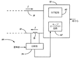
図3は、送信器12の簡略化されたブロック図である。図3に示すように、送信器12はプロセス変数センサ21に接続される測定回路70を含む。回路70は、図2に示したセンサモジュール回路52上に含めることができる。出力ステージ72が測定回路70に接続され、プロセス制御ループ18上に情報を送出(ある実施例では受信)するように構成される。出力ステージ72はループオーバライド回路62および出力回路60を含む。しかしながら、回路60および62は別の実施例に従って構成することができる。測定回路70はセンサ21で感知されるプロセス変数の初期処理を提供するように構成される。測定回路70の実施に際しては、マイクロプロセッサがよく使われる。マイクロプロセッサは図3に示した他の回路を機能的に実施するためにも使用される。
FIG. 3 is a simplified block diagram of the
正常な運転では、センサ21によって感知されたプロセス変数は、プロセス制御ループ18上での伝送のため、出力回路60を使ってアナログ電流レベルまたはデジタル信号に変換される。しかしながら、診断回路64によって警告状態が感知されたとき、ループオーバライド回路62は出力回路60によって生成された出力を無効にするように構成され、ループ18内を搬送される電流レベルIを、予定の警告レベル、例えば予定のしきい値レベル以上または以下に駆動する。ループオーバライド回路62は出力回路60に直列もしくは並列接続されるか、または該回路60中に含めることができる。その他の構成も使用することができる。ある実施例では、ループオーバライド回路62は出力回路60もしくは送信器12内のその他の構成部分を、スイッチを切って停止したり、切り離したりするように構成される。
In normal operation, process variables sensed by
診断回路64はユーザが望むように警告状態を感知することができる。診断回路64は任意の診断技術に従って動作でき、特にここで説明されているものに限定されない。例えば、診断回路64は、送信器12内の個別の構成部分または送信器12内のすべての構成部分の零入力消費電流(quiescent current draw)を感知するように構成することができる。多くの故障メカニズムの兆候は零入力時の「動作」電流レベルの増大によって認識することができる。このことは、2003年8月7日出願の、「零電流診断装置を有するプロセス装置」という名称の米国特許出願第10/635,944号中に記述されている。零入力消費電流に基づいて検出される故障の例は、静電気放電の損傷による潜在的な故障、稲光または瞬間的な電流の流れによる部品の損傷、ツェナーダイオード等、半導体内のリーク、コンデンサ等フィルタ部品のリーク、デンドライト成長すなわち腐食によるリーク、または他の故障もしくは差し迫った故障である。
The
零入力電流診断機能は、零入力電流の増大によって、プロセスループ電流Iを制御することができないことの予測、及び/又は検出を可能にし、これによってループオーバライド回路62を始動する。
The quiescent current diagnostic function enables prediction and / or detection that the process loop current I cannot be controlled by increasing the quiescent current, thereby starting the
零入力電流診断は、専らフィールドバスのようなデジタル形式で通信する装置において特に有利である。このような装置において零入力電流レベルがデジタル信号の送信を妨げた場合、該装置はプロセスに関連する情報を送信する他の手段を有していない。したがって、このような零入力電流診断の構成によって、送信器12は本質的な故障の前に、差し迫った故障の指示を送信することができる。一つの実施例では、ループオーバライド回路62は送信器12の通信回路をプロセス制御ループ18から切り離すことができる。もう一つの実施例では、零入力消費電流が、送信器12またはプロセス制御ループ18の機能が停止するレベルに達したときに、ループオーバライド回路62が送信器12をプロセス制御ループ18から切り離すので、プロセス制御ループ18は動作を継続することができる。
The quiescent current diagnostic is particularly advantageous in devices that communicate exclusively in digital form, such as a fieldbus. If the quiescent current level prevents transmission of a digital signal in such a device, the device has no other means of transmitting process related information. Thus, such a quiescent current diagnostic configuration allows the
図4は、診断回路64の一実施例を示す簡略化されたブロック図である。図4において、比較器74はループ電流Iと直列に接続された抵抗器76での電圧降下を感知するのに使用される。比較器74は予め定められたしきい値を超えるループ電流の変化を検出し、これに応じてループオーバライド回路62に信号を供給するように構成できる。比較器74からの信号に応答して、ループオーバライド回路62は出力回路60の通常動作を無効にしてループ電流Iを警告レベルに駆動する。比較器74は、例えば、上方および下方のしきい値を超える電流の逸脱を検出するための複数の比較器を備えることができる。比較器74への基準入力は、例えば、抵抗ラダーネットワーク、ダイオードなどの適当な手段、または他の手法を使って発生することができる。比較器74の出力はループオーバライド回路62に接続するように記載されている。ループオーバライド回路62は比較器74の出力を受信するマイクロプロセッサを含むことができるか、または比較器74の出力はループオーバライド回路62の電気部品を直接制御するために使用することができる。
FIG. 4 is a simplified block diagram illustrating one embodiment of the
図5は、本発明の他の実施例を示す簡略化された図であり、診断回路64は抵抗器76の両側に接続されたアナログ/デジタル変換器80を使用して構成されている。上述のように、抵抗器76はループ18に直列に接続されているので、該抵抗器76での電圧降下はループ電流Iを示している。アナログ/デジタル変換器80の出力は図7に示したループオーバライド回路62またはマイクロプロセッサ138に接続することができる。マイクロプロセッサはデジタル化されたループ電流値をメモリ内に格納されているしきい値と比較し、その結果によってループオーバライド回路62を始動し、ループ電流を警告信号レベルに駆動する。しきい値は、例えばメモリ内に格納しておくことができる。さらに、診断回路64はループ電流Iを監視してループ電流値の動向を検出することができる。例えば、欠乏(starvation)または電磁妨害(EMI)によるループ電流の動向中の異常はループオーバライド回路62を始動するために使用できる。端子電圧が不十分である場合(つまり欠乏している場合)、出力回路60は所望の出力を行うことができない。電磁妨害のレベルが大きい場合には、ループ電流Iに変化が生じる。もう一つの例では、マイクロプロセッサはデジタル化されたループ電流値をループ電流の期待値と比較することができる。例えば、ループ電流の期待値は、感知されたプロセス変数の特定の値に対応して設定されるべきループ電流値とすることができる。感知されたループ電流値が、電流期待値から予定量、例えば、1パーセント以上変化した場合、マイクロプロセッサはループオーバライド回路62の動作を起動することができる。
FIG. 5 is a simplified diagram illustrating another embodiment of the present invention, in which the
図6Aおよび6Bは出力回路60およびループオーバライド回路62の構成例を示す二つの簡略化されたブロック図である。図6Aにおいて、ループオーバライド回路62は出力回路60と並列に接続されている。ループオーバライド回路62および出力回路60間のオプション的な(任意選択できる)接続が示され、ある実施例ではループオーバライド回路62がループ18から出力回路60を遮断するか、さもなければ切り離す。図6Bでは、ループオーバライド回路62は出力回路60と直列に接続されているように記載されている。ループオーバライド回路62および出力回路60間のオプション的な接続は、ループ18から出力回路60を切り離すか、出力回路60をバイパスするために使用することができる。直列−並列接続、または出力回路60およびループオーバライド回路62のいくつかの部品もしくはすべてを共用する実施例等、他の構成を使用することができる。本装置は、例えば、一つまたはそれ以上のスイッチやヒューズを使うことによってループから電気的に切り離すことができる。
6A and 6B are two simplified block diagrams illustrating exemplary configurations of the
診断回路64によってループ電流を制御できないことが一旦検出されると、ループオーバライド回路62は送信器12が確実に無効警告信号を出力する。例えば、図6Aに示すようにループオーバライド回路62が出力回路60と並列に接続されている場合、ループオーバライド回路62は合計ループ電流がハイアラーム信号を示す21ミリアンペア以上となるように付加的な電流を分流(shunt)することができる。別の実施例では、ループオーバライド回路62は問題となっている回路を切り離すことによってハイアラーム信号およびローアラーム信号のいずれかの送出を可能にする切り離し機構を有する。この実施例では、切り離し回路を前記問題の回路に直列に接続することができる。もう一つの実施例では、ループオーバライド回路62は、必要に応じてループ電流を制御するために使用することができる第2の(つまりバックアップの)ループ制御回路を含むことができる。もう一つの実施例では、診断回路64は、マイクロプロセッサまたは送信器内12内の他の手段によって周期的にトリガされるウォッチドッグ回路150を含む。ウォッチドッグ回路150はハードウェアまたはソフトウェアに含まれる故障を検出することができる。ウォッチドッグ回路150が予定の制限時間以内にトリガされない場合、ループオーバライド回路62が始動されてハイまたはローアラーム信号が送出される。
Once it is detected by the
図7は送信器12内の回路の一例を示すさらに詳細なブロック図である。図7において、シャントレギュレータ100およびループフィードバック抵抗器104を介して2線プロセス制御ループ18に接続される機能モジュール電気回路50が示されている。パワーレギュレータ110がセンサモジュール電気回路52に接続される。また、プロセス変数センサ112を介してプロセスに接続されたセンサモジュール電気回路52が示されている。オプション的な出力表示装置114も示されている。
FIG. 7 is a more detailed block diagram showing an example of a circuit in the
ループオーバライド回路62はデジタル/アナログ(D/A)変換器122およびアナログ/デジタル(A/D)変換器64に接続されるマイクロコントローラ138内に部分的に設けてもよい。アナログ/デジタル変換器64はループ電流を測定するように構成され、かつ診断回路64の機能を備えることもできる。
The
動作中、マイクロコントローラ138は、D/A変換器122およびシャントレギュレータ100を使ってループ18を通る電流Iを制御し、該電流に変調された任意のデジタルデータを乗せるように構成される。アナログ/デジタル変換器64はループ18を流れる電流Iを示す出力を提供する。アナログ/デジタル変換器64はまた送信器12または送信器12内の構成部品によってもたらされる零入力(動作)電流に関連する出力を提供するために接続される。マイクロプロコントローラ138は、警告状態を検出するために使用されるしきい値を格納するメモリ140を有する。測定されたループ電流をメモリ140内に格納されているしきい値と、あるいは感知されたプロセス変数に基づくループ電流の期待値と周期的に比較することによって、マイクロコントローラ138は警告状態が発生したかどうかを判断することができる。もちろん、必要に応じてその他の警告状態を検出でき、本発明はここで説明したものに限定されない。
In operation, the
警告状態が検出されると、マイクロコントローラ138はループオーバライド回路62を始動することによって警告信号をプロセス制御ループ18上に送信する。それから、ループ18を流れる電流Iは固定の電流レベルに設定される。実施例では、所望の出力を供給する他の回路に十分な電力を供給するため、装置内の回路は切り離すか遮断されることができる。ループ無効を提供する一つの手法は装置を切り離すか、さもなければ装置をプロセス制御ループに対してオフラインにすることである。
When a warning condition is detected, the
図7はまたマイクロコントローラ138に接続されたウォッチドッグ回路150を示している。ウォッチドッグ回路150はマイクロコントローラ138によって周期的にトリガされなければならない。マイクロコントローラ138がウォッチドッグ回路150のトリガを停止した場合、故障が発生したと推定される。故障の例としては、不適切なプログラムの流れ、マイクロプロセッサまたはメモリの故障、クロック誤差等を含むが、これらに限定されない。ウォッチドッグ回路150がトリガされない場合、ウォッチドッグ回路150はループオーバライド回路62に信号を送出し、ループオーバライド回路62がプロセス制御ループ18を警告電流レベルに駆動するようにする。
FIG. 7 also shows a
本発明は好ましい実施形態を参照して説明されたが、当業者は形状および細部において本発明の範囲から逸脱しないで変形できることを認識できるであろう。上記は一つの構成例を示したものであり、4−120mA、2,3または4線ループ、マルチ・ドロップループ、およびプロセス制御ループ内を流れる電流を制御することによってプロセス関連情報を送信するフィールドバス、プロファイバス、HART(登録商標)またはその他の通信プロトコルに従って動作するループ等の、適当なプロセス制御ループを任意に使用することができる。本発明は特にプロセス制御ループに対する追加の安全レイヤを提供する安全装置化システム(Safety Instrumented System: SIS)の構成に有用である。本発明はプロセス装置の安全無瑕疵レベル(SIL)評価を向上させる技術を提供することができる。これらの技術は、未発見の故障、つまり潜在的に不安全な状態を、安全状態に従って起きる検出された故障に転換するために使用することができる。それによって、安全装置化システム(SIS)で使用されるプロセス装置用の安全故障フラクション(Safety Failure Fraction: SFF)を増大することができる。本発明は2003年11月21日に管理オーバレイヤ付きプロセス装置という名称で出願された米国出願番号10/719163号で明らかにした技術に関連して使用することができる。 Although the present invention has been described with reference to preferred embodiments, workers skilled in the art will recognize that changes may be made in form and detail without departing from the scope of the invention. The above shows one configuration example, a field for transmitting process related information by controlling the current flowing in a 4-120 mA, 2, 3 or 4 wire loop, a multi-drop loop, and a process control loop. Any suitable process control loop may be used, such as a loop operating according to Bus, Profibers, HART® or other communication protocol. The present invention is particularly useful in the construction of a Safety Instrumented System (SIS) that provides an additional safety layer for process control loops. The present invention can provide a technique for improving the safety integrity level (SIL) evaluation of a process apparatus. These techniques can be used to convert an undiscovered fault, that is, a potentially unsafe condition, into a detected fault that occurs according to the safe condition. Thereby, the Safety Failure Fraction (SFF) for the process equipment used in the Safety Systemization System (SIS) can be increased. The present invention can be used in connection with the technology disclosed in US application Ser. No. 10 / 719,163, filed on Nov. 21, 2003, under the name process equipment with a management overlayer.
10……プロセス制御システム、 12……送信器、 16……プロセスパイプ、 18……2線プロセス制御ループ、 20……制御室、 21……センサ、 60……出力回路、 62……ループオーバライド回路、 64……診断回路、 70……測定回路、 72……出力ステージ 10 ... Process control system, 12 ... Transmitter, 16 ... Process pipe, 18 ... 2-wire process control loop, 20 ... Control room, 21 ... Sensor, 60 ... Output circuit, 62 ... Loop override Circuit, 64 ... Diagnostic circuit, 70 ... Measurement circuit, 72 ... Output stage
Claims (48)
プロセス制御ループ(18)に接続されて該ループを流れる電流を制御し、プロセス関連情報を送信するように構成された出力回路(60)と、
前記出力回路(60)による前記プロセス制御ループ(18)を介した通常動作を無効にして前記プロセス制御ループ(18)内の電流を所望の警告レベルに設定するように構成されており、かつ、前記出力回路(60)と分離して設けられたループオーバライド回路(62)と、
警告状態を検出し、それに応じて前記ループオーバライド回路を作動させて前記出力回路の動作を無効にするように構成された診断回路(64)とを具備するプロセス装置。In a process device (12) used in a process control system,
An output circuit (60) connected to the process control loop (18) and configured to control the current flowing through the loop and to transmit process related information;
Configured to disable normal operation of the output circuit (60) through the process control loop (18) and set the current in the process control loop (18) to a desired warning level ; and A loop override circuit (62) provided separately from the output circuit (60) ;
A process apparatus comprising: a diagnostic circuit (64) configured to detect a warning condition and activate the loop override circuit accordingly to disable operation of the output circuit.
プロセス制御ループに接続されたプロセス装置内の警告状態を検出し、
検出された警告状態に応じて、プロセス制御ループ内の電流を制御するように構成された出力回路(60)の動作を、該出力回路(60)と分離して設けられるループオーバライド回路(62)によって無効にし、
前記出力回路(60)の無効動作の処理の間、前記ループ電流を所望レベルにして該出力回路の動作を無効にするように制御する方法。In a method implemented in a process device (12) that delivers a desired current signal on a process control loop (18),
Detects warning conditions in process equipment connected to the process control loop,
A loop override circuit (62) provided to separate the operation of the output circuit (60) configured to control the current in the process control loop according to the detected warning state from the output circuit (60 ). disable by,
During the processing of the invalid operation of the output circuit (60), the loop current is set to a desired level to control the operation of the output circuit.
Applications Claiming Priority (5)
| Application Number | Priority Date | Filing Date | Title |
|---|---|---|---|
| US10/635,944 | 2003-08-07 | ||
| US10/635,944 US7018800B2 (en) | 2003-08-07 | 2003-08-07 | Process device with quiescent current diagnostics |
| US10/733,558 US7098798B2 (en) | 2003-08-07 | 2003-12-11 | Process device with loop override |
| US10/733,558 | 2003-12-11 | ||
| PCT/US2004/025289 WO2005017851A1 (en) | 2003-08-07 | 2004-08-05 | Process device with loop override |
Publications (3)
| Publication Number | Publication Date |
|---|---|
| JP2007501979A JP2007501979A (en) | 2007-02-01 |
| JP2007501979A5 JP2007501979A5 (en) | 2007-08-30 |
| JP4762140B2 true JP4762140B2 (en) | 2011-08-31 |
Family
ID=34116338
Family Applications (2)
| Application Number | Title | Priority Date | Filing Date |
|---|---|---|---|
| JP2006522716A Expired - Fee Related JP4762140B2 (en) | 2003-08-07 | 2004-08-05 | Process apparatus and method with loop override |
| JP2006522718A Pending JP2007501980A (en) | 2003-08-07 | 2004-08-05 | Process equipment with quiescent current diagnostics |
Family Applications After (1)
| Application Number | Title | Priority Date | Filing Date |
|---|---|---|---|
| JP2006522718A Pending JP2007501980A (en) | 2003-08-07 | 2004-08-05 | Process equipment with quiescent current diagnostics |
Country Status (7)
| Country | Link |
|---|---|
| US (2) | US7018800B2 (en) |
| EP (1) | EP1656564A1 (en) |
| JP (2) | JP4762140B2 (en) |
| CN (2) | CN1864071B (en) |
| DE (1) | DE602004029468D1 (en) |
| RU (1) | RU2350975C2 (en) |
| WO (1) | WO2005017544A1 (en) |
Families Citing this family (68)
| Publication number | Priority date | Publication date | Assignee | Title |
|---|---|---|---|---|
| US8290721B2 (en) * | 1996-03-28 | 2012-10-16 | Rosemount Inc. | Flow measurement diagnostics |
| US8180466B2 (en) * | 2003-11-21 | 2012-05-15 | Rosemount Inc. | Process device with supervisory overlayer |
| US7464721B2 (en) * | 2004-06-14 | 2008-12-16 | Rosemount Inc. | Process equipment validation |
| US7991582B2 (en) * | 2004-09-30 | 2011-08-02 | Rosemount Inc. | Process device with diagnostic annunciation |
| US7222049B2 (en) * | 2005-03-11 | 2007-05-22 | Rosemount, Inc. | User-viewable relative diagnostic output |
| RU2007137820A (en) * | 2005-04-04 | 2009-05-20 | Фишер-Роузмаунт Системз, Инк. (Us) | METHOD FOR STATIC DATA PROCESSING USED FOR DETECTING AN EMERGENCY SITUATION |
| DE102005024686B4 (en) * | 2005-05-30 | 2015-10-22 | Samson Ag | positioner |
| US8112565B2 (en) | 2005-06-08 | 2012-02-07 | Fisher-Rosemount Systems, Inc. | Multi-protocol field device interface with automatic bus detection |
| US20070068225A1 (en) * | 2005-09-29 | 2007-03-29 | Brown Gregory C | Leak detector for process valve |
| US7514652B2 (en) * | 2005-11-16 | 2009-04-07 | Elnar Joseph G | Spa with circuit for detecting excessive ground current |
| US8032234B2 (en) * | 2006-05-16 | 2011-10-04 | Rosemount Inc. | Diagnostics in process control and monitoring systems |
| US7953501B2 (en) | 2006-09-25 | 2011-05-31 | Fisher-Rosemount Systems, Inc. | Industrial process control loop monitor |
| US8788070B2 (en) * | 2006-09-26 | 2014-07-22 | Rosemount Inc. | Automatic field device service adviser |
| US7750642B2 (en) | 2006-09-29 | 2010-07-06 | Rosemount Inc. | Magnetic flowmeter with verification |
| US7683796B2 (en) * | 2006-10-04 | 2010-03-23 | Honeywell International Inc. | Open wire detection system and method |
| US7321846B1 (en) * | 2006-10-05 | 2008-01-22 | Rosemount Inc. | Two-wire process control loop diagnostics |
| US20080211660A1 (en) * | 2006-11-09 | 2008-09-04 | Yokogawa Electric Corporation | Field device system and field device system diagnosing method |
| US7870324B2 (en) * | 2007-02-01 | 2011-01-11 | Siemens Industry, Inc. | Method and apparatus for serial bus communication |
| US8898036B2 (en) | 2007-08-06 | 2014-11-25 | Rosemount Inc. | Process variable transmitter with acceleration sensor |
| US7590511B2 (en) * | 2007-09-25 | 2009-09-15 | Rosemount Inc. | Field device for digital process control loop diagnostics |
| US8265794B2 (en) * | 2007-10-01 | 2012-09-11 | Westlock Controls Corporation | Knowledge based valve control method |
| CN101878415B (en) * | 2007-11-29 | 2012-12-05 | 罗斯蒙德公司 | Process fluid pressure transmitter with pressure transient detection |
| DE102007062919A1 (en) * | 2007-12-21 | 2009-06-25 | Endress + Hauser Gmbh + Co. Kg | Device for diagnosing or determining operating conditions or environmental conditions of field device of process automation technology, comprises voltmeter unit, where effective loop current is determined over voltage drop |
| US7970063B2 (en) * | 2008-03-10 | 2011-06-28 | Rosemount Inc. | Variable liftoff voltage process field device |
| DE102008001832A1 (en) * | 2008-05-16 | 2009-11-19 | Endress + Hauser Flowtec Ag | Measuring instrument with measuring and operating electronics for monitoring a measuring signal |
| US8390150B2 (en) * | 2008-07-15 | 2013-03-05 | Fisher-Rosemount Systems, Inc. | Field device interface with network protection mechanism |
| EP2187185B1 (en) * | 2008-11-17 | 2016-03-16 | VEGA Grieshaber KG | Field device with separate storage areas |
| EP2228632B1 (en) * | 2009-03-11 | 2018-10-03 | VEGA Grieshaber KG | Radiometric measuring device with dual cable supply |
| EP2236999B1 (en) * | 2009-04-01 | 2020-11-18 | VEGA Grieshaber KG | Field device with two processors |
| EP2246984B1 (en) | 2009-04-28 | 2013-07-03 | VEGA Grieshaber KG | Diagnosis apparatus for monitoring an analogue-digital conversion apparatus |
| US8786128B2 (en) * | 2010-05-11 | 2014-07-22 | Rosemount Inc. | Two-wire industrial process field device with power scavenging |
| US10761524B2 (en) * | 2010-08-12 | 2020-09-01 | Rosemount Inc. | Wireless adapter with process diagnostics |
| DE102010039271A1 (en) | 2010-08-12 | 2012-02-16 | Endress + Hauser Gmbh + Co. Kg | Circuit for controlling and monitoring a signal current and a transmitter with such a circuit |
| DE102010041731A1 (en) * | 2010-09-30 | 2012-04-05 | Endress + Hauser Wetzer Gmbh + Co Kg | Recover procedure for a device with an analog current output for the output of a measured value or a manipulated variable |
| JP5141790B2 (en) * | 2010-10-05 | 2013-02-13 | 横河電機株式会社 | 2-wire transmitter |
| US8519863B2 (en) * | 2010-10-15 | 2013-08-27 | Rosemount Inc. | Dynamic power control for a two wire process instrument |
| DE102010063949A1 (en) * | 2010-12-22 | 2012-06-28 | Endress + Hauser Gmbh + Co. Kg | gauge |
| US9207670B2 (en) | 2011-03-21 | 2015-12-08 | Rosemount Inc. | Degrading sensor detection implemented within a transmitter |
| JP5604351B2 (en) * | 2011-03-30 | 2014-10-08 | アズビル株式会社 | Field equipment |
| US9020768B2 (en) * | 2011-08-16 | 2015-04-28 | Rosemount Inc. | Two-wire process control loop current diagnostics |
| JP5812276B2 (en) * | 2011-10-31 | 2015-11-11 | 横河電機株式会社 | 2-wire transmitter |
| DE102012000187B4 (en) * | 2012-01-09 | 2014-02-27 | Krohne Messtechnik Gmbh | Method for monitoring a transmitter and corresponding transmitters |
| CA2873034C (en) * | 2012-05-29 | 2019-03-12 | Rosemount Inc. | Process control loop current verification |
| US9052240B2 (en) | 2012-06-29 | 2015-06-09 | Rosemount Inc. | Industrial process temperature transmitter with sensor stress diagnostics |
| US9602122B2 (en) | 2012-09-28 | 2017-03-21 | Rosemount Inc. | Process variable measurement noise diagnostic |
| DE102012113047A1 (en) | 2012-12-21 | 2014-06-26 | Endress + Hauser Wetzer Gmbh + Co Kg | Operating electronics for a process device and method for operating the same |
| US9222844B2 (en) * | 2013-02-25 | 2015-12-29 | Rosemount Inc. | Process temperature transmitter with improved sensor diagnostics |
| US9575091B2 (en) * | 2013-03-15 | 2017-02-21 | Kenneth Mark Reeder, III | Testing device for electrical safety using wireless communication |
| US9404515B2 (en) * | 2013-07-09 | 2016-08-02 | Dresser, Inc. | Valve positioner having bypass component and control value comprised thereof |
| DE102014208432A1 (en) * | 2014-05-06 | 2015-11-12 | Continental Teves Ag & Co. Ohg | PSI5 interface with temperature-independent error monitoring |
| DE102016200693A1 (en) * | 2015-01-21 | 2016-07-21 | Siemens Aktiengesellschaft | Monitoring module for a field device, use of a monitoring module and method for its operation |
| US10082784B2 (en) | 2015-03-30 | 2018-09-25 | Rosemount Inc. | Saturation-controlled loop current regulator |
| US9863980B2 (en) * | 2015-05-22 | 2018-01-09 | Rosemount Tank Radar Ab | Loop-powered field device with voltage regulator and current source in series |
| US10367612B2 (en) | 2015-09-30 | 2019-07-30 | Rosemount Inc. | Process variable transmitter with self-learning loop diagnostics |
| US11078711B1 (en) * | 2016-06-23 | 2021-08-03 | Elcon, Inc. | Methods and systems for automatically determining level of unclosed door in chute applications |
| RU2642807C1 (en) * | 2016-11-11 | 2018-01-26 | Общество с ограниченной ответственностью "Научно-Технический Центр Завод Балансировочных машин" | System for signal transmission from sensors with analogue output via a two-wireless line (options) |
| US10365702B2 (en) * | 2017-04-10 | 2019-07-30 | International Business Machines Corporation | Autonomic supply voltage compensation for degradation of circuits over circuit lifetime |
| DE102017110633B3 (en) * | 2017-05-16 | 2018-11-15 | Krohne Messtechnik Gmbh | Display device for process automation |
| US10937299B2 (en) | 2017-06-08 | 2021-03-02 | Rosemount Inc. | Current diagnostics for field devices |
| JP6769418B2 (en) * | 2017-09-25 | 2020-10-14 | 株式会社デンソー | Current controller |
| US20200133254A1 (en) * | 2018-05-07 | 2020-04-30 | Strong Force Iot Portfolio 2016, Llc | Methods and systems for data collection, learning, and streaming of machine signals for part identification and operating characteristics determination using the industrial internet of things |
| DE102018114302B3 (en) | 2018-06-14 | 2019-11-21 | Endress+Hauser SE+Co. KG | Diagnosis of a two-wire field device |
| CN109188049B (en) * | 2018-08-31 | 2020-12-22 | 惠州华阳通用电子有限公司 | Method and device for detecting dark current of vehicle-mounted equipment |
| CN109238557A (en) * | 2018-11-27 | 2019-01-18 | 青岛大学 | A kind of intelligent self-diagnosing formula pressure transmitter device |
| JP7010205B2 (en) * | 2018-12-25 | 2022-01-26 | 横河電機株式会社 | 2-wire transmitter |
| US20220373614A1 (en) * | 2019-09-20 | 2022-11-24 | Nordson Corporation | Systems and methods for direct heater diagnostics for a hot melt liquid dispensing system |
| CN113728283A (en) * | 2020-03-26 | 2021-11-30 | 罗斯蒙特公司 | Two-wire industrial process field device power supply circuitry |
| EP4242597A1 (en) * | 2022-03-07 | 2023-09-13 | Rosemount Tank Radar AB | Alarm handling in loop-powered field device |
Citations (7)
| Publication number | Priority date | Publication date | Assignee | Title |
|---|---|---|---|---|
| JPS61109337A (en) * | 1984-11-02 | 1986-05-27 | Mitsubishi Heavy Ind Ltd | Controller of multiplex transmission system |
| JPS63197197A (en) * | 1987-02-12 | 1988-08-16 | Mitsubishi Electric Corp | Load control system |
| JPH02227670A (en) * | 1989-01-10 | 1990-09-10 | Philips Gloeilampenfab:Nv | Zero input current measuring apparatus |
| JPH05216501A (en) * | 1992-02-06 | 1993-08-27 | Toshiba Corp | Output circuit for digital controller |
| JPH11182443A (en) * | 1997-12-16 | 1999-07-06 | Yutani Heavy Ind Ltd | Control unit of variable displacement hydraulic pump |
| JP2002062903A (en) * | 2000-08-21 | 2002-02-28 | Yokogawa Electric Corp | Control device |
| WO2003060851A1 (en) * | 2002-01-18 | 2003-07-24 | Endress + Hauser Gmbh + Co. Kg | Sensor arrangement |
Family Cites Families (197)
| Publication number | Priority date | Publication date | Assignee | Title |
|---|---|---|---|---|
| US3096434A (en) | 1961-11-28 | 1963-07-02 | Daniel Orifice Fitting Company | Multiple integration flow computer |
| US3404264A (en) | 1965-07-19 | 1968-10-01 | American Meter Co | Telemetering system for determining rate of flow |
| US3468164A (en) | 1966-08-26 | 1969-09-23 | Westinghouse Electric Corp | Open thermocouple detection apparatus |
| GB1224904A (en) | 1968-08-09 | 1971-03-10 | John Stewart Simpson Stewart | Improvements in and relating to electromedical apparatus |
| US3590370A (en) | 1969-04-09 | 1971-06-29 | Leeds & Northrup Co | Method and apparatus for detecting the open-circuit condition of a thermocouple by sending a pulse through the thermocouple and a reactive element in series |
| US3701280A (en) | 1970-03-18 | 1972-10-31 | Daniel Ind Inc | Method and apparatus for determining the supercompressibility factor of natural gas |
| US3691842A (en) | 1970-09-08 | 1972-09-19 | Beckman Instruments Inc | Differential pressure transducer |
| US3688190A (en) | 1970-09-25 | 1972-08-29 | Beckman Instruments Inc | Differential capacitance circuitry for differential pressure measuring instruments |
| US3849637A (en) | 1973-05-22 | 1974-11-19 | Combustion Eng | Reactor megawatt demand setter |
| US3855858A (en) | 1973-08-01 | 1974-12-24 | V Cushing | Self synchronous noise rejection circuit for fluid velocity meter |
| USRE29383E (en) | 1974-01-10 | 1977-09-06 | Process Systems, Inc. | Digital fluid flow rate measurement or control system |
| US3948098A (en) * | 1974-04-24 | 1976-04-06 | The Foxboro Company | Vortex flow meter transmitter including piezo-electric sensor |
| GB1488304A (en) | 1974-06-20 | 1977-10-12 | Yukogawa Electric Works Ltd | Signal transmission system |
| US3952759A (en) | 1974-08-14 | 1976-04-27 | M & J Valve Company | Liquid line break control system and method |
| US3973184A (en) | 1975-01-27 | 1976-08-03 | Leeds & Northrup Company | Thermocouple circuit detector for simultaneous analog trend recording and analog to digital conversion |
| JPS51122751A (en) | 1975-04-21 | 1976-10-27 | Yokogawa Hokushin Electric Corp | D-c control currint supply means |
| US4058975A (en) | 1975-12-08 | 1977-11-22 | General Electric Company | Gas turbine temperature sensor validation apparatus and method |
| US4020416A (en) | 1976-05-20 | 1977-04-26 | Rca Corporation | Method of detecting heater resistance independent of contact resistance |
| US4099413A (en) | 1976-06-25 | 1978-07-11 | Yokogawa Electric Works, Ltd. | Thermal noise thermometer |
| US4102199A (en) | 1976-08-26 | 1978-07-25 | Megasystems, Inc. | RTD measurement system |
| US4122719A (en) | 1977-07-08 | 1978-10-31 | Environmental Systems Corporation | System for accurate measurement of temperature |
| JPS54111050A (en) | 1978-02-21 | 1979-08-31 | Toyota Motor Corp | Automatic speed changer |
| JPS5523638A (en) | 1978-08-09 | 1980-02-20 | Hitachi Ltd | Failure detection unit for transmission control unit |
| US4250490A (en) | 1979-01-19 | 1981-02-10 | Rosemount Inc. | Two wire transmitter for converting a varying signal from a remote reactance sensor to a DC current signal |
| US4249164A (en) | 1979-05-14 | 1981-02-03 | Tivy Vincent V | Flow meter |
| US4279013A (en) | 1979-10-31 | 1981-07-14 | The Valeron Corporation | Machine process controller |
| US4337516A (en) | 1980-06-26 | 1982-06-29 | United Technologies Corporation | Sensor fault detection by activity monitoring |
| US4403297A (en) | 1981-01-02 | 1983-09-06 | Loveland Controls Company | Process control system prover |
| US4417312A (en) | 1981-06-08 | 1983-11-22 | Worcester Controls Corporation | Electronic controller for valve actuators |
| US4459858A (en) * | 1981-09-18 | 1984-07-17 | Marsh-Mcbirney, Inc. | Flow meter having an electromagnetic sensor probe |
| US4399824A (en) | 1981-10-05 | 1983-08-23 | Air-Shields, Inc. | Apparatus for detecting probe dislodgement |
| US4463612A (en) * | 1981-12-10 | 1984-08-07 | The Babcock & Wilcox Company | Electronic circuit using digital techniques for vortex shedding flowmeter signal processing |
| US4571689A (en) | 1982-10-20 | 1986-02-18 | The United States Of America As Represented By The Secretary Of The Air Force | Multiple thermocouple testing device |
| US4668473A (en) | 1983-04-25 | 1987-05-26 | The Babcock & Wilcox Company | Control system for ethylene polymerization reactor |
| US4530234A (en) | 1983-06-30 | 1985-07-23 | Mobil Oil Corporation | Method and system for measuring properties of fluids |
| JPH0619666B2 (en) | 1983-06-30 | 1994-03-16 | 富士通株式会社 | Failure diagnosis processing method |
| US4540468A (en) | 1983-09-26 | 1985-09-10 | Board Of Trustees Of The University Of Maine | Method for determining the degree of completion and pulp yield |
| US4707796A (en) | 1983-10-19 | 1987-11-17 | Calabro Salvatore R | Reliability and maintainability indicator |
| US4686638A (en) | 1983-11-04 | 1987-08-11 | Kabushiki Kaisha Kosumo Keiki | Leakage inspection method with object type compensation |
| EP0158192B1 (en) | 1984-03-31 | 1991-06-05 | B a r m a g AG | Measurement data acquisition method for a plurality of measurement points |
| US4649515A (en) | 1984-04-30 | 1987-03-10 | Westinghouse Electric Corp. | Methods and apparatus for system fault diagnosis and control |
| US4517468A (en) | 1984-04-30 | 1985-05-14 | Westinghouse Electric Corp. | Diagnostic system and method |
| US4642782A (en) | 1984-07-31 | 1987-02-10 | Westinghouse Electric Corp. | Rule based diagnostic system with dynamic alteration capability |
| US4644479A (en) | 1984-07-31 | 1987-02-17 | Westinghouse Electric Corp. | Diagnostic apparatus |
| US4630265A (en) | 1984-09-26 | 1986-12-16 | General Electric Company | Method and apparatus for selecting for use between data buses in a redundant bus communication system |
| JPH0734162B2 (en) | 1985-02-06 | 1995-04-12 | 株式会社日立製作所 | Analogical control method |
| US4758308A (en) | 1985-03-05 | 1988-07-19 | Carr Wayne F | System for monitoring contaminants with a detector in a paper pulp stream |
| US5179540A (en) * | 1985-11-08 | 1993-01-12 | Harris Corporation | Programmable chip enable logic function |
| US4807151A (en) | 1986-04-11 | 1989-02-21 | Purdue Research Foundation | Electrical technique for correcting bridge type mass air flow rate sensor errors resulting from ambient temperature variations |
| GB8611360D0 (en) | 1986-05-09 | 1986-06-18 | Eaton Williams Raymond H | Air condition monitor unit |
| US4736367A (en) | 1986-12-22 | 1988-04-05 | Chrysler Motors Corporation | Smart control and sensor devices single wire bus multiplex system |
| US5005142A (en) | 1987-01-30 | 1991-04-02 | Westinghouse Electric Corp. | Smart sensor system for diagnostic monitoring |
| US4736763A (en) | 1987-02-26 | 1988-04-12 | Britton George L | Automatic device for the detection and shutoff of unwanted liquid flow in pipes |
| DE3877873D1 (en) | 1987-04-02 | 1993-03-11 | Eftag Entstaubung Foerdertech | CIRCUIT ARRANGEMENT FOR EVALUATING THE SIGNALS GENERATED BY A SEMICONDUCTOR GAS SENSOR. |
| US4808958A (en) * | 1987-07-23 | 1989-02-28 | Bourns Instruments, Inc. | Linear variable differential transformer with improved secondary windings |
| US5122794A (en) | 1987-08-11 | 1992-06-16 | Rosemount Inc. | Dual master implied token communication system |
| US4988990A (en) | 1989-05-09 | 1991-01-29 | Rosemount Inc. | Dual master implied token communication system |
| US4873655A (en) | 1987-08-21 | 1989-10-10 | Board Of Regents, The University Of Texas System | Sensor conditioning method and apparatus |
| US4907167A (en) | 1987-09-30 | 1990-03-06 | E. I. Du Pont De Nemours And Company | Process control system with action logging |
| US4804958A (en) | 1987-10-09 | 1989-02-14 | Rosemount Inc. | Two-wire transmitter with threshold detection circuit |
| US4818994A (en) | 1987-10-22 | 1989-04-04 | Rosemount Inc. | Transmitter with internal serial bus |
| US4831564A (en) | 1987-10-22 | 1989-05-16 | Suga Test Instruments Co., Ltd. | Apparatus for estimating and displaying remainder of lifetime of xenon lamps |
| US5274572A (en) | 1987-12-02 | 1993-12-28 | Schlumberger Technology Corporation | Method and apparatus for knowledge-based signal monitoring and analysis |
| US5488697A (en) * | 1988-01-12 | 1996-01-30 | Honeywell Inc. | Problem state monitoring system |
| US5193143A (en) | 1988-01-12 | 1993-03-09 | Honeywell Inc. | Problem state monitoring |
| US4841286A (en) | 1988-02-08 | 1989-06-20 | Honeywell Inc. | Apparatus and method for detection of an open thermocouple in a process control network |
| US4924418A (en) | 1988-02-10 | 1990-05-08 | Dickey-John Corporation | Universal monitor |
| JPH0774961B2 (en) | 1988-04-07 | 1995-08-09 | 株式会社日立製作所 | Auto tuning PID controller |
| US4926364A (en) | 1988-07-25 | 1990-05-15 | Westinghouse Electric Corp. | Method and apparatus for determining weighted average of process variable |
| US4964125A (en) | 1988-08-19 | 1990-10-16 | Hughes Aircraft Company | Method and apparatus for diagnosing faults |
| US5197328A (en) | 1988-08-25 | 1993-03-30 | Fisher Controls International, Inc. | Diagnostic apparatus and method for fluid control valves |
| US5099436A (en) | 1988-11-03 | 1992-03-24 | Allied-Signal Inc. | Methods and apparatus for performing system fault diagnosis |
| US5067099A (en) | 1988-11-03 | 1991-11-19 | Allied-Signal Inc. | Methods and apparatus for monitoring system performance |
| GB2224853A (en) | 1988-11-12 | 1990-05-16 | David Mawdsley | Measuring current |
| EP0369489A3 (en) | 1988-11-18 | 1991-11-27 | Omron Corporation | Sensor controller system |
| US5025344A (en) * | 1988-11-30 | 1991-06-18 | Carnegie Mellon University | Built-in current testing of integrated circuits |
| US5036886A (en) | 1988-12-12 | 1991-08-06 | Olson Controls, Inc. | Digital servo valve system |
| JP2714091B2 (en) | 1989-01-09 | 1998-02-16 | 株式会社日立製作所 | Field instrument |
| US5098197A (en) | 1989-01-30 | 1992-03-24 | The United States Of America As Represented By The United States Department Of Energy | Optical Johnson noise thermometry |
| US5089979A (en) | 1989-02-08 | 1992-02-18 | Basic Measuring Instruments | Apparatus for digital calibration of detachable transducers |
| US5081598A (en) | 1989-02-21 | 1992-01-14 | Westinghouse Electric Corp. | Method for associating text in automatic diagnostic system to produce recommended actions automatically |
| US4939753A (en) | 1989-02-24 | 1990-07-03 | Rosemount Inc. | Time synchronization of control networks |
| US5089984A (en) | 1989-05-15 | 1992-02-18 | Allen-Bradley Company, Inc. | Adaptive alarm controller changes multiple inputs to industrial controller in order for state word to conform with stored state word |
| US4934196A (en) | 1989-06-02 | 1990-06-19 | Micro Motion, Inc. | Coriolis mass flow rate meter having a substantially increased noise immunity |
| US5269311A (en) | 1989-08-29 | 1993-12-14 | Abbott Laboratories | Method for compensating errors in a pressure transducer |
| US5293585A (en) * | 1989-08-31 | 1994-03-08 | Kabushiki Kaisha Toshiba | Industrial expert system |
| JP2656637B2 (en) * | 1989-11-22 | 1997-09-24 | 株式会社日立製作所 | Process control system and power plant process control system |
| JPH03166601A (en) | 1989-11-27 | 1991-07-18 | Hitachi Ltd | Symbolizing device and process controller and control supporting device using the symbolizing device |
| US5019760A (en) | 1989-12-07 | 1991-05-28 | Electric Power Research Institute | Thermal life indicator |
| US5111531A (en) | 1990-01-08 | 1992-05-05 | Automation Technology, Inc. | Process control using neural network |
| US5235527A (en) | 1990-02-09 | 1993-08-10 | Toyota Jidosha Kabushiki Kaisha | Method for diagnosing abnormality of sensor |
| US5134574A (en) | 1990-02-27 | 1992-07-28 | The Foxboro Company | Performance control apparatus and method in a processing plant |
| US5122976A (en) | 1990-03-12 | 1992-06-16 | Westinghouse Electric Corp. | Method and apparatus for remotely controlling sensor processing algorithms to expert sensor diagnoses |
| US5053815A (en) | 1990-04-09 | 1991-10-01 | Eastman Kodak Company | Reproduction apparatus having real time statistical process control |
| US5150289A (en) | 1990-07-30 | 1992-09-22 | The Foxboro Company | Method and apparatus for process control |
| US5197114A (en) | 1990-08-03 | 1993-03-23 | E. I. Du Pont De Nemours & Co., Inc. | Computer neural network regulatory process control system and method |
| US5121467A (en) | 1990-08-03 | 1992-06-09 | E.I. Du Pont De Nemours & Co., Inc. | Neural network/expert system process control system and method |
| US5224203A (en) | 1990-08-03 | 1993-06-29 | E. I. Du Pont De Nemours & Co., Inc. | On-line process control neural network using data pointers |
| US5282261A (en) * | 1990-08-03 | 1994-01-25 | E. I. Du Pont De Nemours And Co., Inc. | Neural network process measurement and control |
| US5212765A (en) * | 1990-08-03 | 1993-05-18 | E. I. Du Pont De Nemours & Co., Inc. | On-line training neural network system for process control |
| US5142612A (en) | 1990-08-03 | 1992-08-25 | E. I. Du Pont De Nemours & Co. (Inc.) | Computer neural network supervisory process control system and method |
| US5167009A (en) | 1990-08-03 | 1992-11-24 | E. I. Du Pont De Nemours & Co. (Inc.) | On-line process control neural network using data pointers |
| US5175678A (en) | 1990-08-15 | 1992-12-29 | Elsag International B.V. | Method and procedure for neural control of dynamic processes |
| US5130936A (en) | 1990-09-14 | 1992-07-14 | Arinc Research Corporation | Method and apparatus for diagnostic testing including a neural network for determining testing sufficiency |
| US5223798A (en) | 1990-10-31 | 1993-06-29 | The United States Of America As Represented By The Secretary Of The Navy | Method for measuring the resistive transition and critical current in superconductors using pulsed current |
| US5265031A (en) | 1990-11-26 | 1993-11-23 | Praxair Technology, Inc. | Diagnostic gas monitoring process utilizing an expert system |
| US5214582C1 (en) | 1991-01-30 | 2001-06-26 | Edge Diagnostic Systems | Interactive diagnostic system for an automobile vehicle and method |
| US5143452A (en) | 1991-02-04 | 1992-09-01 | Rockwell International Corporation | System for interfacing a single sensor unit with multiple data processing modules |
| AU660661B2 (en) * | 1991-02-05 | 1995-07-06 | Storage Technology Corporation | Knowledge based machine initiated maintenance system |
| JP2636527B2 (en) | 1991-03-04 | 1997-07-30 | 三菱電機株式会社 | Insulation degradation prevention and insulation degradation prediction diagnostic equipment for electrical equipment storage equipment |
| US5137370A (en) | 1991-03-25 | 1992-08-11 | Delta M Corporation | Thermoresistive sensor system |
| GB2260416B (en) | 1991-10-10 | 1995-07-26 | Smiths Industries Plc | Resistance monitors |
| GB9121506D0 (en) * | 1991-10-10 | 1991-11-27 | Smiths Industries Plc | Resistance monitors |
| WO1993012410A1 (en) * | 1991-12-13 | 1993-06-24 | Honeywell Inc. | Piezoresistive silicon pressure sensor design |
| JP2646512B2 (en) * | 1991-12-25 | 1997-08-27 | アスモ株式会社 | Resin injection bearing for small motor |
| US5282131A (en) | 1992-01-21 | 1994-01-25 | Brown And Root Industrial Services, Inc. | Control system for controlling a pulp washing system using a neural network controller |
| US5285152A (en) | 1992-03-23 | 1994-02-08 | Ministar Peripherals International Limited | Apparatus and methods for testing circuit board interconnect integrity |
| DE4209785C2 (en) | 1992-03-26 | 1994-04-21 | Knick Elektronische Mesgeraete | Transmission system for signals |
| JP2783059B2 (en) * | 1992-04-23 | 1998-08-06 | 株式会社日立製作所 | Process state detection device, semiconductor sensor and its status display device |
| FR2692037B1 (en) * | 1992-06-03 | 1997-08-08 | Thomson Csf | DIAGNOSTIC PROCESS OF AN EVOLVING PROCESS. |
| GB2267783B (en) * | 1992-06-09 | 1996-08-28 | British Aerospace | Beam forming |
| CA2097558C (en) * | 1992-06-16 | 2001-08-21 | William B. Kilgore | Directly connected display of process control system in an open systems windows environment |
| US5384699A (en) * | 1992-08-24 | 1995-01-24 | Associated Universities, Inc. | Preventive maintenance system for the photomultiplier detector blocks of pet scanners |
| US5228780A (en) | 1992-10-30 | 1993-07-20 | Martin Marietta Energy Systems, Inc. | Dual-mode self-validating resistance/Johnson noise thermometer system |
| US5388465A (en) * | 1992-11-17 | 1995-02-14 | Yamatake-Honeywell Co., Ltd. | Electromagnetic flowmeter |
| US5386188A (en) * | 1993-01-15 | 1995-01-31 | Keithley Instruments, Inc. | In-circuit current measurement |
| US5486996A (en) * | 1993-01-22 | 1996-01-23 | Honeywell Inc. | Parameterized neurocontrollers |
| US5339025A (en) | 1993-01-28 | 1994-08-16 | The United States Of America As Represented By The Secretary Of The Navy | Method for determining the granular nature of superconductors using pulsed current |
| US5392293A (en) * | 1993-02-26 | 1995-02-21 | At&T Corp. | Built-in current sensor for IDDQ testing |
| US5394341A (en) * | 1993-03-25 | 1995-02-28 | Ford Motor Company | Apparatus for detecting the failure of a sensor |
| US5410495A (en) * | 1993-07-20 | 1995-04-25 | Texas Instruments Incorporated | Apparatus, systems, and methods for diagnosing anomalous mass flow controller operation |
| US5386373A (en) * | 1993-08-05 | 1995-01-31 | Pavilion Technologies, Inc. | Virtual continuous emission monitoring system with sensor validation |
| US5404064A (en) * | 1993-09-02 | 1995-04-04 | The United States Of America As Represented By The Secretary Of The Navy | Low-frequency electrostrictive ceramic plate voltage sensor |
| AU7562394A (en) * | 1993-09-07 | 1995-03-27 | Rosemount Inc. | Multivariable transmitter |
| US5481200A (en) * | 1993-09-15 | 1996-01-02 | Rosemont Inc. | Field transmitter built-in test equipment |
| US5489831A (en) * | 1993-09-16 | 1996-02-06 | Honeywell Inc. | Pulse width modulating motor controller |
| US5481199A (en) * | 1993-09-24 | 1996-01-02 | Anderson; Karl F. | System for improving measurement accuracy of transducer by measuring transducer temperature and resistance change using thermoelectric voltages |
| US5408406A (en) * | 1993-10-07 | 1995-04-18 | Honeywell Inc. | Neural net based disturbance predictor for model predictive control |
| US6010612A (en) * | 1993-11-22 | 2000-01-04 | E.I. Du Pont De Nemours And Company | Production of isocyanate using chlorine recycle |
| WO1995016923A1 (en) * | 1993-12-16 | 1995-06-22 | Philips Electronics N.V. | Separate iddq-testing of signal path and bias path in an ic |
| FR2720498B1 (en) * | 1994-05-27 | 1996-08-09 | Schlumberger Services Petrol | Multiphase flowmeter. |
| US5483387A (en) * | 1994-07-22 | 1996-01-09 | Honeywell, Inc. | High pass optical filter |
| US5608650A (en) * | 1994-08-19 | 1997-03-04 | Spectrel Partners, L.L.C. | Systems and methods for testing pump flow rates |
| US5623605A (en) * | 1994-08-29 | 1997-04-22 | Lucent Technologies Inc. | Methods and systems for interprocess communication and inter-network data transfer |
| US5669713A (en) * | 1994-09-27 | 1997-09-23 | Rosemount Inc. | Calibration of process control temperature transmitter |
| EP0710904B1 (en) * | 1994-10-25 | 1998-10-07 | Rieter Ingolstadt Spinnereimaschinenbau AG | Backplane-control for spinning-machine |
| US5570034A (en) * | 1994-12-29 | 1996-10-29 | Intel Corporation | Using hall effect to monitor current during IDDQ testing of CMOS integrated circuits |
| US5600148A (en) * | 1994-12-30 | 1997-02-04 | Honeywell Inc. | Low power infrared scene projector array and method of manufacture |
| US5708585A (en) * | 1995-03-20 | 1998-01-13 | General Motors Corporation | Combustible gas measurement |
| US5741074A (en) * | 1995-06-06 | 1998-04-21 | Thermo Electrioc Corporation | Linear integrated sensing transmitter sensor |
| US5742845A (en) * | 1995-06-22 | 1998-04-21 | Datascape, Inc. | System for extending present open network communication protocols to communicate with non-standard I/O devices directly coupled to an open network |
| US5736649A (en) * | 1995-08-23 | 1998-04-07 | Tokico Ltd. | Vortex flowmeter |
| US5705978A (en) * | 1995-09-29 | 1998-01-06 | Rosemount Inc. | Process control transmitter |
| JP3263296B2 (en) * | 1995-10-26 | 2002-03-04 | 株式会社東芝 | Electromagnetic flow meter |
| ES2139985T3 (en) * | 1995-10-26 | 2000-02-16 | Flowtec Ag | FLOW SENSOR ACCORDING TO THE PRINCIPLE OF CORIOLIS WITH A SINGLE TUBE. |
| US6014902A (en) * | 1995-12-28 | 2000-01-18 | The Foxboro Company | Magnetic flowmeter with diagnostics |
| US5700090A (en) * | 1996-01-03 | 1997-12-23 | Rosemount Inc. | Temperature sensor transmitter with sensor sheath lead |
| US6209048B1 (en) * | 1996-02-09 | 2001-03-27 | Ricoh Company, Ltd. | Peripheral with integrated HTTP server for remote access using URL's |
| DE19611520A1 (en) * | 1996-03-23 | 1997-09-25 | Bosch Gmbh Robert | System for testing a computer installed in a control unit |
| US6539267B1 (en) * | 1996-03-28 | 2003-03-25 | Rosemount Inc. | Device in a process system for determining statistical parameter |
| US6017143A (en) * | 1996-03-28 | 2000-01-25 | Rosemount Inc. | Device in a process system for detecting events |
| US5909368A (en) * | 1996-04-12 | 1999-06-01 | Fisher-Rosemount Systems, Inc. | Process control system using a process control strategy distributed among multiple control elements |
| US5710370A (en) * | 1996-05-17 | 1998-01-20 | Dieterich Technology Holding Corp. | Method for calibrating a differential pressure fluid flow measuring system |
| US5708211A (en) * | 1996-05-28 | 1998-01-13 | Ohio University | Flow regime determination and flow measurement in multiphase flow pipelines |
| US5781024A (en) * | 1996-07-26 | 1998-07-14 | Diametrics Medical, Inc. | Instrument performance verification system |
| US5713668A (en) * | 1996-08-23 | 1998-02-03 | Accutru International Corporation | Self-verifying temperature sensor |
| US6023399A (en) * | 1996-09-24 | 2000-02-08 | Hitachi, Ltd. | Decentralized control system and shutdown control apparatus |
| WO1998014855A1 (en) * | 1996-10-04 | 1998-04-09 | Fisher Controls International, Inc. | Maintenance interface device for use in a process control network |
| JP3993243B2 (en) * | 1996-10-04 | 2007-10-17 | フィッシャー コントロールズ インターナショナル リミテッド ライアビリティー カンパニー | Network accessible interface for process control network |
| US6047222A (en) * | 1996-10-04 | 2000-04-04 | Fisher Controls International, Inc. | Process control network with redundant field devices and buses |
| US5859964A (en) * | 1996-10-25 | 1999-01-12 | Advanced Micro Devices, Inc. | System and method for performing real time data acquisition, process modeling and fault detection of wafer fabrication processes |
| US5956663A (en) * | 1996-11-07 | 1999-09-21 | Rosemount, Inc. | Signal processing technique which separates signal components in a sensor for sensor diagnostics |
| US5719378A (en) * | 1996-11-19 | 1998-02-17 | Illinois Tool Works, Inc. | Self-calibrating temperature controller |
| US5869772A (en) * | 1996-11-27 | 1999-02-09 | Storer; William James A. | Vortex flowmeter including cantilevered vortex and vibration sensing beams |
| EP0948759B1 (en) | 1996-12-31 | 2002-08-07 | Rosemount Inc. | Device in a process system for validating a control signal from a field device |
| JPH10198657A (en) * | 1997-01-08 | 1998-07-31 | Toshiba Corp | Signal processor |
| JPH10261185A (en) * | 1997-03-19 | 1998-09-29 | Hitachi Ltd | Input/output coexisting type signal converter |
| US6002952A (en) * | 1997-04-14 | 1999-12-14 | Masimo Corporation | Signal processing apparatus and method |
| US6014612A (en) * | 1997-10-02 | 2000-01-11 | Fisher Controls International, Inc. | Remote diagnostics in a process control network having distributed control functions |
| AU9795598A (en) * | 1997-10-13 | 1999-05-03 | Rosemount Inc. | Communication technique for field devices in industrial processes |
| FI116587B (en) | 1997-10-17 | 2005-12-30 | Metso Automation Oy | Method and apparatus for verifying the proper functioning of the restraint |
| JPH11118657A (en) * | 1997-10-21 | 1999-04-30 | Cosmo Keiki:Kk | Drift correction value calculator and leakage detector equipped with calculator |
| US6199018B1 (en) * | 1998-03-04 | 2001-03-06 | Emerson Electric Co. | Distributed diagnostic system |
| US6016523A (en) * | 1998-03-09 | 2000-01-18 | Schneider Automation, Inc. | I/O modular terminal having a plurality of data registers and an identification register and providing for interfacing between field devices and a field master |
| US6360277B1 (en) * | 1998-07-22 | 2002-03-19 | Crydom Corporation | Addressable intelligent relay |
| US6046642A (en) * | 1998-09-08 | 2000-04-04 | Motorola, Inc. | Amplifier with active bias compensation and method for adjusting quiescent current |
| DE29824256U1 (en) | 1998-12-14 | 2001-06-13 | Wratil Peter | Unit for the safety monitoring of control devices |
| DE19905071A1 (en) * | 1999-02-08 | 2000-08-10 | Siemens Ag | Transmitter and method for diagnosing the supply of a transmitter |
| DE19927635B4 (en) | 1999-06-17 | 2009-10-15 | Phoenix Contact Gmbh & Co. Kg | Security related automation bus system |
| US6445963B1 (en) * | 1999-10-04 | 2002-09-03 | Fisher Rosemount Systems, Inc. | Integrated advanced control blocks in process control systems |
| DE10034684A1 (en) * | 2000-07-17 | 2002-01-31 | Endress Hauser Gmbh Co | Measuring device for measuring a process variable |
| US6970003B2 (en) | 2001-03-05 | 2005-11-29 | Rosemount Inc. | Electronics board life prediction of microprocessor-based transmitters |
| US7149597B2 (en) * | 2001-05-29 | 2006-12-12 | John Billings | Process control system and method |
| EP1396771B1 (en) | 2001-05-31 | 2016-02-17 | Omron Corporation | Slave units and network system as well as slave unit processing method and device information collecting method |
| US6772036B2 (en) * | 2001-08-30 | 2004-08-03 | Fisher-Rosemount Systems, Inc. | Control system using process model |
| DE10154002A1 (en) | 2001-11-02 | 2003-05-22 | Siemens Ag | Arrangement with a peripheral unit, which is connected via a two-wire line to a central unit |
| EP1440290B1 (en) | 2001-11-02 | 2013-01-30 | Siemens Aktiengesellschaft | Measuring transducer |
-
2003
- 2003-08-07 US US10/635,944 patent/US7018800B2/en active Active
- 2003-12-11 US US10/733,558 patent/US7098798B2/en not_active Expired - Lifetime
-
2004
- 2004-08-05 JP JP2006522716A patent/JP4762140B2/en not_active Expired - Fee Related
- 2004-08-05 JP JP2006522718A patent/JP2007501980A/en active Pending
- 2004-08-05 CN CN2004800295163A patent/CN1864071B/en active Active
- 2004-08-05 DE DE602004029468T patent/DE602004029468D1/de active Active
- 2004-08-05 WO PCT/US2004/025291 patent/WO2005017544A1/en active Search and Examination
- 2004-08-05 CN CNB2004800295159A patent/CN100472575C/en active Active
- 2004-08-05 EP EP04757422A patent/EP1656564A1/en not_active Ceased
- 2004-08-05 RU RU2006106911/28A patent/RU2350975C2/en not_active IP Right Cessation
Patent Citations (7)
| Publication number | Priority date | Publication date | Assignee | Title |
|---|---|---|---|---|
| JPS61109337A (en) * | 1984-11-02 | 1986-05-27 | Mitsubishi Heavy Ind Ltd | Controller of multiplex transmission system |
| JPS63197197A (en) * | 1987-02-12 | 1988-08-16 | Mitsubishi Electric Corp | Load control system |
| JPH02227670A (en) * | 1989-01-10 | 1990-09-10 | Philips Gloeilampenfab:Nv | Zero input current measuring apparatus |
| JPH05216501A (en) * | 1992-02-06 | 1993-08-27 | Toshiba Corp | Output circuit for digital controller |
| JPH11182443A (en) * | 1997-12-16 | 1999-07-06 | Yutani Heavy Ind Ltd | Control unit of variable displacement hydraulic pump |
| JP2002062903A (en) * | 2000-08-21 | 2002-02-28 | Yokogawa Electric Corp | Control device |
| WO2003060851A1 (en) * | 2002-01-18 | 2003-07-24 | Endress + Hauser Gmbh + Co. Kg | Sensor arrangement |
Also Published As
| Publication number | Publication date |
|---|---|
| CN1864183A (en) | 2006-11-15 |
| EP1656564A1 (en) | 2006-05-17 |
| CN1864071B (en) | 2010-08-11 |
| US7098798B2 (en) | 2006-08-29 |
| JP2007501980A (en) | 2007-02-01 |
| CN1864071A (en) | 2006-11-15 |
| US20050030185A1 (en) | 2005-02-10 |
| RU2350975C2 (en) | 2009-03-27 |
| US20050030186A1 (en) | 2005-02-10 |
| RU2006106911A (en) | 2006-08-10 |
| DE602004029468D1 (en) | 2010-11-18 |
| US7018800B2 (en) | 2006-03-28 |
| WO2005017544A1 (en) | 2005-02-24 |
| JP2007501979A (en) | 2007-02-01 |
| CN100472575C (en) | 2009-03-25 |
Similar Documents
| Publication | Publication Date | Title |
|---|---|---|
| JP4762140B2 (en) | Process apparatus and method with loop override | |
| EP2067088B1 (en) | Two-wire process control loop diagnostics | |
| JP4050236B2 (en) | Portable diagnostic communication device with automatic bus detection | |
| JP4916445B2 (en) | Process device with diagnostic notification | |
| US9288289B2 (en) | Portable device maintenance support apparatus, system, and method | |
| US10599134B2 (en) | Portable field maintenance tool configured for multiple process control communication protocols | |
| RU2395830C2 (en) | Process device with supervisory overlayer | |
| US10764083B2 (en) | Portable field maintenance tool with resistor network for intrinsically safe operation | |
| US10505585B2 (en) | Portable field maintenance tool with a bus for powering and communicating with a field device | |
| EP1652160B1 (en) | Process device with loop override | |
| GB2552588A (en) | Portable field maintenance tool with resistor network for intrinsically safe operation |
Legal Events
| Date | Code | Title | Description |
|---|---|---|---|
| A521 | Written amendment |
Free format text: JAPANESE INTERMEDIATE CODE: A523 Effective date: 20070712 |
|
| A621 | Written request for application examination |
Free format text: JAPANESE INTERMEDIATE CODE: A621 Effective date: 20070712 |
|
| A131 | Notification of reasons for refusal |
Free format text: JAPANESE INTERMEDIATE CODE: A131 Effective date: 20100310 |
|
| A521 | Written amendment |
Free format text: JAPANESE INTERMEDIATE CODE: A523 Effective date: 20100514 |
|
| A131 | Notification of reasons for refusal |
Free format text: JAPANESE INTERMEDIATE CODE: A131 Effective date: 20101027 |
|
| A521 | Written amendment |
Free format text: JAPANESE INTERMEDIATE CODE: A523 Effective date: 20110125 |
|
| TRDD | Decision of grant or rejection written | ||
| A01 | Written decision to grant a patent or to grant a registration (utility model) |
Free format text: JAPANESE INTERMEDIATE CODE: A01 Effective date: 20110525 |
|
| A01 | Written decision to grant a patent or to grant a registration (utility model) |
Free format text: JAPANESE INTERMEDIATE CODE: A01 |
|
| A61 | First payment of annual fees (during grant procedure) |
Free format text: JAPANESE INTERMEDIATE CODE: A61 Effective date: 20110607 |
|
| FPAY | Renewal fee payment (event date is renewal date of database) |
Free format text: PAYMENT UNTIL: 20140617 Year of fee payment: 3 |
|
| R150 | Certificate of patent or registration of utility model |
Ref document number: 4762140 Country of ref document: JP Free format text: JAPANESE INTERMEDIATE CODE: R150 Free format text: JAPANESE INTERMEDIATE CODE: R150 |
|
| R250 | Receipt of annual fees |
Free format text: JAPANESE INTERMEDIATE CODE: R250 |
|
| R250 | Receipt of annual fees |
Free format text: JAPANESE INTERMEDIATE CODE: R250 |
|
| R250 | Receipt of annual fees |
Free format text: JAPANESE INTERMEDIATE CODE: R250 |
|
| R250 | Receipt of annual fees |
Free format text: JAPANESE INTERMEDIATE CODE: R250 |
|
| R250 | Receipt of annual fees |
Free format text: JAPANESE INTERMEDIATE CODE: R250 |
|
| R250 | Receipt of annual fees |
Free format text: JAPANESE INTERMEDIATE CODE: R250 |
|
| R250 | Receipt of annual fees |
Free format text: JAPANESE INTERMEDIATE CODE: R250 |
|
| LAPS | Cancellation because of no payment of annual fees |