JP4759587B2 - Wind farm - Google Patents
Wind farm Download PDFInfo
- Publication number
- JP4759587B2 JP4759587B2 JP2008105235A JP2008105235A JP4759587B2 JP 4759587 B2 JP4759587 B2 JP 4759587B2 JP 2008105235 A JP2008105235 A JP 2008105235A JP 2008105235 A JP2008105235 A JP 2008105235A JP 4759587 B2 JP4759587 B2 JP 4759587B2
- Authority
- JP
- Japan
- Prior art keywords
- power
- wind power
- wind
- charge
- plant
- Prior art date
- Legal status (The legal status is an assumption and is not a legal conclusion. Google has not performed a legal analysis and makes no representation as to the accuracy of the status listed.)
- Expired - Fee Related
Links
- 238000010248 power generation Methods 0.000 claims description 168
- 238000011084 recovery Methods 0.000 claims description 156
- 238000007600 charging Methods 0.000 claims description 108
- 230000000116 mitigating effect Effects 0.000 claims description 21
- 239000007789 gas Substances 0.000 description 19
- 238000000034 method Methods 0.000 description 18
- 230000000694 effects Effects 0.000 description 10
- 230000005284 excitation Effects 0.000 description 9
- 230000001360 synchronised effect Effects 0.000 description 9
- 239000002253 acid Substances 0.000 description 7
- 238000007599 discharging Methods 0.000 description 7
- 230000019635 sulfation Effects 0.000 description 7
- 238000005670 sulfation reaction Methods 0.000 description 7
- 101100298996 Arabidopsis thaliana PBC2 gene Proteins 0.000 description 6
- 101150020457 PBC1 gene Proteins 0.000 description 6
- 230000007423 decrease Effects 0.000 description 6
- 238000004891 communication Methods 0.000 description 5
- 230000006698 induction Effects 0.000 description 5
- PIJPYDMVFNTHIP-UHFFFAOYSA-L lead sulfate Chemical compound [PbH4+2].[O-]S([O-])(=O)=O PIJPYDMVFNTHIP-UHFFFAOYSA-L 0.000 description 5
- 102100026205 1-phosphatidylinositol 4,5-bisphosphate phosphodiesterase gamma-1 Human genes 0.000 description 4
- 101100190617 Arabidopsis thaliana PLC2 gene Proteins 0.000 description 4
- 101100190618 Arabidopsis thaliana PLC3 gene Proteins 0.000 description 4
- 101100408456 Arabidopsis thaliana PLC8 gene Proteins 0.000 description 4
- 101100464304 Caenorhabditis elegans plk-3 gene Proteins 0.000 description 4
- 101000691599 Homo sapiens 1-phosphatidylinositol 4,5-bisphosphate phosphodiesterase gamma-1 Proteins 0.000 description 4
- 101100093534 Saccharomyces cerevisiae (strain ATCC 204508 / S288c) RPS1B gene Proteins 0.000 description 4
- 239000013078 crystal Substances 0.000 description 4
- 239000000446 fuel Substances 0.000 description 4
- 239000000470 constituent Substances 0.000 description 3
- 238000001514 detection method Methods 0.000 description 2
- 239000003792 electrolyte Substances 0.000 description 2
- 239000003915 liquefied petroleum gas Substances 0.000 description 2
- 230000007774 longterm Effects 0.000 description 2
- VNWKTOKETHGBQD-UHFFFAOYSA-N methane Chemical compound C VNWKTOKETHGBQD-UHFFFAOYSA-N 0.000 description 2
- 230000000737 periodic effect Effects 0.000 description 2
- 101100257262 Caenorhabditis elegans soc-1 gene Proteins 0.000 description 1
- UFHFLCQGNIYNRP-UHFFFAOYSA-N Hydrogen Chemical compound [H][H] UFHFLCQGNIYNRP-UHFFFAOYSA-N 0.000 description 1
- BNOODXBBXFZASF-UHFFFAOYSA-N [Na].[S] Chemical compound [Na].[S] BNOODXBBXFZASF-UHFFFAOYSA-N 0.000 description 1
- 230000005540 biological transmission Effects 0.000 description 1
- 238000010280 constant potential charging Methods 0.000 description 1
- 238000010277 constant-current charging Methods 0.000 description 1
- 238000002425 crystallisation Methods 0.000 description 1
- 230000008025 crystallization Effects 0.000 description 1
- 230000006866 deterioration Effects 0.000 description 1
- 238000010586 diagram Methods 0.000 description 1
- 239000003502 gasoline Substances 0.000 description 1
- 239000007788 liquid Substances 0.000 description 1
- 239000003345 natural gas Substances 0.000 description 1
- 238000002360 preparation method Methods 0.000 description 1
- 101150114085 soc-2 gene Proteins 0.000 description 1
Images


Classifications
-
- F—MECHANICAL ENGINEERING; LIGHTING; HEATING; WEAPONS; BLASTING
- F03—MACHINES OR ENGINES FOR LIQUIDS; WIND, SPRING, OR WEIGHT MOTORS; PRODUCING MECHANICAL POWER OR A REACTIVE PROPULSIVE THRUST, NOT OTHERWISE PROVIDED FOR
- F03D—WIND MOTORS
- F03D7/00—Controlling wind motors
- F03D7/02—Controlling wind motors the wind motors having rotation axis substantially parallel to the air flow entering the rotor
- F03D7/04—Automatic control; Regulation
- F03D7/042—Automatic control; Regulation by means of an electrical or electronic controller
- F03D7/048—Automatic control; Regulation by means of an electrical or electronic controller controlling wind farms
-
- F—MECHANICAL ENGINEERING; LIGHTING; HEATING; WEAPONS; BLASTING
- F03—MACHINES OR ENGINES FOR LIQUIDS; WIND, SPRING, OR WEIGHT MOTORS; PRODUCING MECHANICAL POWER OR A REACTIVE PROPULSIVE THRUST, NOT OTHERWISE PROVIDED FOR
- F03D—WIND MOTORS
- F03D9/00—Adaptations of wind motors for special use; Combinations of wind motors with apparatus driven thereby; Wind motors specially adapted for installation in particular locations
- F03D9/10—Combinations of wind motors with apparatus storing energy
- F03D9/11—Combinations of wind motors with apparatus storing energy storing electrical energy
-
- F—MECHANICAL ENGINEERING; LIGHTING; HEATING; WEAPONS; BLASTING
- F03—MACHINES OR ENGINES FOR LIQUIDS; WIND, SPRING, OR WEIGHT MOTORS; PRODUCING MECHANICAL POWER OR A REACTIVE PROPULSIVE THRUST, NOT OTHERWISE PROVIDED FOR
- F03D—WIND MOTORS
- F03D9/00—Adaptations of wind motors for special use; Combinations of wind motors with apparatus driven thereby; Wind motors specially adapted for installation in particular locations
- F03D9/20—Wind motors characterised by the driven apparatus
- F03D9/25—Wind motors characterised by the driven apparatus the apparatus being an electrical generator
- F03D9/255—Wind motors characterised by the driven apparatus the apparatus being an electrical generator connected to electrical distribution networks; Arrangements therefor
- F03D9/257—Wind motors characterised by the driven apparatus the apparatus being an electrical generator connected to electrical distribution networks; Arrangements therefor the wind motor being part of a wind farm
-
- F—MECHANICAL ENGINEERING; LIGHTING; HEATING; WEAPONS; BLASTING
- F05—INDEXING SCHEMES RELATING TO ENGINES OR PUMPS IN VARIOUS SUBCLASSES OF CLASSES F01-F04
- F05B—INDEXING SCHEME RELATING TO WIND, SPRING, WEIGHT, INERTIA OR LIKE MOTORS, TO MACHINES OR ENGINES FOR LIQUIDS COVERED BY SUBCLASSES F03B, F03D AND F03G
- F05B2240/00—Components
- F05B2240/90—Mounting on supporting structures or systems
- F05B2240/96—Mounting on supporting structures or systems as part of a wind turbine farm
-
- F—MECHANICAL ENGINEERING; LIGHTING; HEATING; WEAPONS; BLASTING
- F05—INDEXING SCHEMES RELATING TO ENGINES OR PUMPS IN VARIOUS SUBCLASSES OF CLASSES F01-F04
- F05B—INDEXING SCHEME RELATING TO WIND, SPRING, WEIGHT, INERTIA OR LIKE MOTORS, TO MACHINES OR ENGINES FOR LIQUIDS COVERED BY SUBCLASSES F03B, F03D AND F03G
- F05B2270/00—Control
- F05B2270/30—Control parameters, e.g. input parameters
- F05B2270/335—Output power or torque
-
- Y—GENERAL TAGGING OF NEW TECHNOLOGICAL DEVELOPMENTS; GENERAL TAGGING OF CROSS-SECTIONAL TECHNOLOGIES SPANNING OVER SEVERAL SECTIONS OF THE IPC; TECHNICAL SUBJECTS COVERED BY FORMER USPC CROSS-REFERENCE ART COLLECTIONS [XRACs] AND DIGESTS
- Y02—TECHNOLOGIES OR APPLICATIONS FOR MITIGATION OR ADAPTATION AGAINST CLIMATE CHANGE
- Y02E—REDUCTION OF GREENHOUSE GAS [GHG] EMISSIONS, RELATED TO ENERGY GENERATION, TRANSMISSION OR DISTRIBUTION
- Y02E10/00—Energy generation through renewable energy sources
- Y02E10/70—Wind energy
- Y02E10/72—Wind turbines with rotation axis in wind direction
-
- Y—GENERAL TAGGING OF NEW TECHNOLOGICAL DEVELOPMENTS; GENERAL TAGGING OF CROSS-SECTIONAL TECHNOLOGIES SPANNING OVER SEVERAL SECTIONS OF THE IPC; TECHNICAL SUBJECTS COVERED BY FORMER USPC CROSS-REFERENCE ART COLLECTIONS [XRACs] AND DIGESTS
- Y02—TECHNOLOGIES OR APPLICATIONS FOR MITIGATION OR ADAPTATION AGAINST CLIMATE CHANGE
- Y02E—REDUCTION OF GREENHOUSE GAS [GHG] EMISSIONS, RELATED TO ENERGY GENERATION, TRANSMISSION OR DISTRIBUTION
- Y02E70/00—Other energy conversion or management systems reducing GHG emissions
- Y02E70/30—Systems combining energy storage with energy generation of non-fossil origin
Landscapes
- Engineering & Computer Science (AREA)
- Combustion & Propulsion (AREA)
- Life Sciences & Earth Sciences (AREA)
- Sustainable Development (AREA)
- Sustainable Energy (AREA)
- Chemical & Material Sciences (AREA)
- Mechanical Engineering (AREA)
- General Engineering & Computer Science (AREA)
- Power Engineering (AREA)
- Charge And Discharge Circuits For Batteries Or The Like (AREA)
- Supply And Distribution Of Alternating Current (AREA)
- Wind Motors (AREA)
- Control Of Electrical Variables (AREA)
- Secondary Cells (AREA)
Description
本発明は、風力発電システムと、蓄電システムを備えた風力発電所に関するものである。 The present invention relates to a wind power generation system and a wind power plant equipped with a power storage system.
自然界に存在する再生可能なエネルギーを電力エネルギーに変換する手段として、風力発電システムが利用されている。風力発電システムのエネルギー源は、時間的に変動する風のエネルギーであるため、風力発電システムの発電電力も時間的に変動する。発電電力変動を緩和するために、風力発電機に蓄電システムを併設する場合がある。併設する蓄電システムは、鉛電池やナトリウム硫黄電池等の二次電池と電力変換器などで構成される。特に二次電池として鉛電池を用いた場合、放電状態で長期間放置すると、鉛電池電極に硫酸鉛の結晶が析出する、いわゆるサルフェーションが発生する。サルフェーションが発生すると鉛蓄電池の特性が著しく劣化する。このため鉛蓄電池を電力変動の緩和を目的として使用する際には、鉛蓄電池を定期的に過充電状態にし、サルフェーションの発生を防止する回復充電を行うことが一般的である。 A wind power generation system is used as a means for converting renewable energy existing in nature to electric power energy. Since the energy source of the wind power generation system is wind energy that varies with time, the power generated by the wind power generation system also varies with time. In order to mitigate fluctuations in generated power, a wind power generator may be provided with a power storage system. The power storage system to be provided is composed of a secondary battery such as a lead battery or a sodium-sulfur battery and a power converter. In particular, when a lead battery is used as a secondary battery, so-called sulfation occurs in which lead sulfate crystals are deposited on the lead battery electrode when left in a discharged state for a long period of time. When sulfation occurs, the characteristics of the lead-acid battery deteriorate significantly. For this reason, when a lead storage battery is used for the purpose of mitigating power fluctuations, it is common to perform a recovery charge to prevent the occurrence of sulfation by periodically putting the lead storage battery into an overcharged state.
風力発電機に併設した鉛蓄電池の従来の回復充電方法として、例えば〔特許文献1〕が挙げられる。〔特許文献1〕では、風力発電機の発電電力が一定値以下になった際に回復充電を行うとの記載がある。さらに〔特許文献1〕では、回復充電のある段階においては、風力発電機出力電力の変動緩和を行うことができないため、風力発電機の運転を停止するとの記載がある。 As a conventional recovery charging method for a lead storage battery provided in combination with a wind power generator, for example, [Patent Document 1] can be cited. [Patent Document 1] describes that recovery charging is performed when the power generated by the wind power generator becomes a certain value or less. Furthermore, in [Patent Document 1], there is a description that the operation of the wind power generator is stopped because the fluctuation of the wind power generator output power cannot be reduced at a stage where recovery charging is performed.
鉛蓄電池を併設した風力発電システムにおいて、電力変動の緩和効果を維持したまま自然エネルギーを有効利用するためには、鉛蓄電池の定期的な回復充電を確実に実施し、鉛蓄電池の劣化を防止する必要がある。このためには、鉛蓄電池の回復充電を風の強さに影響されずに実施する必要がある。また自然エネルギーの有効利用のためには、回復充電中であっても風力発電システムは発電運転を継続することが望ましい。 In a wind power generation system with a lead-acid battery, in order to effectively use natural energy while maintaining the effect of mitigating power fluctuations, the lead-acid battery must be periodically recharged to prevent deterioration of the lead-acid battery. There is a need. For this purpose, it is necessary to carry out recovery charging of the lead-acid battery without being affected by the wind strength. In order to effectively use natural energy, it is desirable that the wind power generation system continues the power generation operation even during recovery charging.
本発明の克服すべき課題は、風力発電システム周辺の風速の大きさに影響を受けず、確実に鉛蓄電池の回復充電を行う蓄電システムを備えた風力発電所を提供することである。 The problem to be overcome by the present invention is to provide a wind power plant including a power storage system that reliably recovers and charges a lead storage battery without being affected by the wind speed around the wind power generation system.
上記課題を解決するために、本発明は、風力発電システムと蓄電システムを備え、前記風力発電システムは1台以上の風力発電装置を有し、前記蓄電システムは2台以上の蓄電装置を有し、該複数の蓄電装置は構成要素に2次電池を備えて、電力系統に接続された風力発電所において、該風力発電所は風力発電システムの発電電力を検出する手段と、前記複数の蓄電装置の充放電電力の合計値を検出する手段と、前記発電電力と前記充放電電力を受信するコントローラを備え、該コントローラは前記風力発電所の電力変動を緩和する前記蓄電システムの充放電電力指令を演算する手段を備え、前記複数の蓄電装置のうち1台以上が回復充電状態にある時に、前記風力発電所は前記風力発電所の出力電力の変動を緩和するように前記複数の蓄電装置のうち非回復充電状態にある前記蓄電装置の充放電電力を調整する手段を備えることを特徴とするものである。 In order to solve the above problems, the present invention includes a wind power generation system and a power storage system, the wind power generation system includes one or more wind power generation devices, and the power storage system includes two or more power storage devices. The plurality of power storage devices each include a secondary battery as a component, and the wind power plant is connected to an electric power system. The wind power plant detects a power generated by the wind power generation system, and the plurality of power storage devices. And a controller for receiving the generated power and the charge / discharge power, and the controller outputs a charge / discharge power command for the power storage system to mitigate power fluctuations of the wind power plant. Means for calculating, and when one or more of the plurality of power storage devices are in a recovery charge state, the wind power plant is configured to relieve fluctuations in output power of the wind power plant. It is characterized in that it comprises means for adjusting the charge-discharge electric power of said power storage device in a non-recovery charging state of the location.
また、本発明では、風力発電所において、非回復充電状態にある前記蓄電装置が、回復充電状態にある前記蓄電装置に対して回復充電のための電力の一部、あるいは全てを供給する手段を持つことを特徴とするものである。 Further, in the present invention, in the wind power plant, the power storage device in the non-recovery charge state supplies means for supplying a part or all of the power for recovery charge to the power storage device in the recovery charge state. It is characterized by having.
また、本発明では、風力発電所において、前記風力発電システムの発電電力の変動が所定値より大きかった場合には、回復充電状態にある前記蓄電装置が回復充電を停止し、前記風力発電所の出力電力の変動を緩和するように充放電電力を調整する手段を持つことを特徴とするものである。 In the present invention, in the wind power plant, when the fluctuation of the generated power of the wind power generation system is larger than a predetermined value, the power storage device in the recovery charge state stops the recovery charge, and the wind power plant It has a means for adjusting charge / discharge power so as to reduce fluctuations in output power.
また、本発明では、風力発電所において、前記複数の蓄電装置の少なくとも1台以上が回復充電状態にある場合には、前記風力発電システムの発電電力制限値を、前記蓄電システムに回復充電状態の蓄電装置が無い状態の発電電力制限値より小さな値にする手段を持つことを特徴とするものである。 In the present invention, when at least one of the plurality of power storage devices is in the recovery charge state in the wind power plant, the generated power limit value of the wind power generation system is set to the power storage system in the recovery charge state. It has a means to make it a value smaller than the generated power limit value in the state where there is no power storage device.
上記課題を解決するために、本発明は、風力発電システムと蓄電システムを備えた風力発電所であって、該風力発電所は電力系統に接続し、前記風力発電所は気象予測データに基づく風力発電システムの発電電力の予測値を入手する手段と、前記風力発電所が前記風力発電システムの発電電力予測値に基づいて、前記蓄電システムの回復充電をスケジューリングする手段を備えることを特徴とするものである。 In order to solve the above problems, the present invention is a wind power plant including a wind power generation system and a power storage system, wherein the wind power plant is connected to a power system, and the wind power plant is a wind power plant based on weather forecast data. Means for obtaining a predicted value of the generated power of the power generation system, and means for scheduling recovery charging of the power storage system based on the predicted power generation value of the wind power generation system by the wind power plant. It is.
更に、上記課題を解決するために、本発明は、風力発電システムと、蓄電システムと及び補助発電機とを備え、前記風力発電システムは1台以上の風力発電装置を有し、前記蓄電システムは2台以上の蓄電装置を有し、該複数の蓄電装置は構成要素に2次電池を備えて、電力系統に接続された風力発電所において、前記風力発電所は風力発電システムの発電電力を検出する手段と、前記複数の蓄電装置の充放電電力の合計値PBを検出する手段と、前記補助発電機の発電電力を検出する手段と、前記風力発電所は前記発電電力と前記充放電電力と前記補助発電機の発電電力を受信するコントローラを備え、該コントローラは前記風力発電所の電力変動を緩和する前記蓄電システムの充放電電力指令を演算する手段を備え、該コントローラは前記補助発電機の発電電力指令を演算する手段と、前記発電電力指令を前記補助発電機に送信する手段を備え、前記複数の蓄電装置のうち少なくとも1台以上が回復充電状態にある際に、前記補助発電機が回復充電のための電力の一部、あるいは全てを供給する手段を備えることを特徴とするものである。 Furthermore, in order to solve the above-described problem, the present invention includes a wind power generation system, a power storage system, and an auxiliary generator, and the wind power generation system includes one or more wind power generation devices, and the power storage system includes: The wind power plant has two or more power storage devices, each of the plurality of power storage devices includes a secondary battery as a component, and the wind power plant detects power generated by the wind power generation system. Means for detecting a total value PB of charge / discharge power of the plurality of power storage devices, means for detecting generated power of the auxiliary generator, and the wind power plant includes the generated power and the charge / discharge power. A controller for receiving the power generated by the auxiliary generator, the controller comprising means for calculating a charge / discharge power command for the power storage system to mitigate power fluctuations of the wind power plant, Means for calculating the generated power command of the auxiliary generator, and means for transmitting the generated power command to the auxiliary generator, and when at least one of the plurality of power storage devices is in the recovery charge state, The auxiliary generator is provided with means for supplying part or all of the electric power for recovery charging.
また、本発明では、風力発電所において、前記蓄電システムの回復充電の際に、前記風力発電所の出力電力が所定値以下になるように、前記風力発電システムの発電電力を調整する手段を備えることを特徴とするものである。 In the present invention, the wind power plant includes means for adjusting the generated power of the wind power generation system so that the output power of the wind power plant is equal to or less than a predetermined value when the power storage system is recovered and charged. It is characterized by this.
更に、上記課題を解決するために、本発明は、風力発電システムと蓄電システムを備え、前記風力発電システムは1台以上の風力発電装置を有し、前記蓄電システムは2台以上の蓄電装置を有し、該複数の蓄電装置は構成要素に2次電池を備えて、電力系統に接続された風力発電所において、前記風力発電所は風力発電システムの発電電力を検出する手段と、複数の蓄電装置の充放電電力の合計値を検出する手段と、前記風力発電所が電力系統と連系する地点において前記風力発電所の出力電力を検出する手段とを備え、前記風力発電所は前記風力発電システムの発電電力と前記充放電電力の合計値と前記風力発電所の出力電力を受信するコントローラを備え、前記コントローラは前記風力発電システムの発電電力と前記充放電電力の合計値と前記風力発電所の出力電力から前記風力発電所の構成要素が発生する損失を演算する手段と、前記蓄電システムに送信する充放電電力指令を演算する手段と、前記充放電電力指令に対して前記損失を補正する手段とを備えることを特徴とするものである。 Furthermore, in order to solve the above problems, the present invention includes a wind power generation system and a power storage system, the wind power generation system includes one or more wind power generation devices, and the power storage system includes two or more power storage devices. A plurality of power storage devices, each of which includes a secondary battery as a component, wherein the wind power plant is connected to a power system, and the wind power plant detects a power generated by the wind power generation system; Means for detecting a total value of charging / discharging power of the apparatus, and means for detecting output power of the wind power plant at a point where the wind power plant is connected to a power system, the wind power plant having the wind power generation A controller for receiving a total value of the generated power of the system, the charge / discharge power, and an output power of the wind power plant, wherein the controller is a total value of the generated power of the wind power generation system and the charge / discharge power; Means for calculating a loss generated by the components of the wind power plant from output power of the wind power plant, means for calculating a charge / discharge power command to be transmitted to the power storage system, and the charge / discharge power command And a means for correcting the loss.
本発明を用いることで、風力発電システムが発電運転中において、ある一台の蓄電装置が回復充電を行っても、他の蓄電装置が風力発電所出力電力の変動緩和を行うため、風力発電システムを停止する必要が無い。 By using the present invention, even when one power storage device performs recovery charging while the wind power generation system is in power generation operation, the other power storage device reduces fluctuations in the output power of the wind power plant. There is no need to stop.
また風が弱く風力発電システムが運転していなくても、非回復充電状態の蓄電装置が電力を供給することで、電力系統から回復充電のための電力を受電することなく回復充電状態の蓄電装置が回復充電を完遂することを可能とする。このため風力発電システム周辺の風速の大きさとは無関係に確実に回復充電を行うことが可能であり、また回復充電中も自然エネルギーを有効利用できる。 In addition, even when the wind power generation system is not operating due to weak wind, the power storage device in the non-recovery charge state supplies power, so that the power storage device in the recovery charge state without receiving power for recovery charge from the power system Makes it possible to complete the recovery charge. Therefore, it is possible to reliably perform recovery charging regardless of the wind speed around the wind power generation system, and natural energy can be effectively used even during recovery charging.
以下本発明の一実施例を図面に基づいて説明する。 An embodiment of the present invention will be described below with reference to the drawings.
図1に本実施例の風力発電所の全体像を示す。本発明の風力発電所は、風力発電システム1と蓄電システム2,上位コントローラ3,連系変圧器4等で構成され、発電した電力を電力系統5に送電する。風力発電システム1の連系点には、電力計6を設置し風力発電システム1の発電電力PWを測定する。また蓄電システム2の連系点には、電力計7を設置し蓄電システム2の充放電電力PBを測定する。さらに風力発電所の連系点には電力計8を設置し、風力発電所の出力電力PSを測定する。風力発電所出力電力PSと、風力発電システム発電電力PW,蓄電システム充放電電力PBの間には(数1)の関係が成り立つ。
FIG. 1 shows an overall view of the wind power plant of the present embodiment. The wind power plant of the present invention includes a wind
(数1)PS=PW+PB−(補正量1)
補正量1は電力計6と、電力計7,電力計8の間を接続する配電線、連系変圧器4等による損失を表す。
(Equation 1) PS = PW + PB− (correction amount 1)
The
上位コントローラ3は、風力発電システム1の発電電力PW、蓄電システム2の充放電電力PBから風力発電所の出力電力PSの変動が緩和されるように蓄電池の充放電電力指令を作成する。上位コントローラ3は、各蓄電装置2−1−1,2−1−2,2−1−3に充放電電力指令PBC1,PBC2,PBC3を送信し、各蓄電装置2−1−1,2−1−2,2−1−3は充放電電力指令に従って充放電を行う。また上位コントローラ3は各蓄電装置2−1−1,2−1−2,2−1−3が回復充電モードに移行するタイミングを決める回復充電指令を送信する。回復充電指令を受信した蓄電装置は、変動緩和のための充放電を停止し、回復充電を行う。上位コントローラ3は風力発電所の出力電力PSの変動が緩和されるように、風力発電システム1の発電電力制限指令PLC0を作成する。発電電力制限指令PLC0は風力発電システムを構成するSCADA1−2に送信され、SCADA1−2は各風力発電装置1−1−1,1−1−2,1−1−3にそれぞれ発電電力制限指令PLC1,PLC2,PLC3を送信する。なお発電電力制限指令PLC0と、各風力発電装置の発電電力制限指令PLC1,PLC2,PLC3には(数2)に示す関係式が成り立つ。
The
(数2)PLC0=PLC1+PLC2+PLC3
各風力発電装置1−1−1,1−1−2,1−1−3はそれぞれの発電電力がPLC1,PLC2,PLC3以上にならないように発電電力を制御する。以上のようなシステム構成,制御方法を用いることにより本発明の風力発電所は、風力発電所の出力電力PSの出力電力を所定値PLO以下に抑制する。なお図1に示した風力発電システム1は風力発電装置3台で構成されるが、本発明は風力発電システム1が少なくとも1台以上の風力発電装置で構成されれば良く、本発明の効果は風力発電装置の台数に限定されるものではない。
(Expression 2) PLC0 = PLC1 + PLC2 + PLC3
Each wind power generator 1-1-1, 1-1-2, 1-1-3 controls the generated power so that the generated power does not exceed PLC1, PLC2, PLC3. By using the system configuration and control method as described above, the wind power plant of the present invention suppresses the output power of the output power PS of the wind power plant to a predetermined value PLO or less. The wind
次に図2〜図5を用いて風力発電装置1−1−1,1−1−2,1−1−3について詳細に説明する。図2は、風力発電装置の一形態を示した図である。風力発電装置1−1−1は、ブレード1−1−1−1により風を受け、風のエネルギーを回転エネルギーに変換する。回転エネルギーは、発電機1−1−1−4に伝達される。風力発電装置1−1−1は風速計1−1−1−2を用いて風力発電装置1−1−1周辺の風速の大きさ、及び風向を測定している。風力発電装置1−1−1は風速計1−1−1−2の測定値を基に、ナセル1−1−1−10の水平方向の向きや、ブレード1−1−1−1のピッチ角を制御することで発電運転を実現する。 Next, the wind power generators 1-1-1, 1-1-2, and 1-1-3 will be described in detail with reference to FIGS. FIG. 2 is a diagram showing an embodiment of the wind power generator. The wind power generator 1-1-1 receives wind by the blade 1-1-1-1 and converts wind energy into rotational energy. The rotational energy is transmitted to the generator 1-1-1-4. The wind power generator 1-1-1 measures the magnitude and direction of wind around the wind power generator 1-1-1 using an anemometer 1-1-1-2. The wind power generator 1-1-1 is based on the measured value of the anemometer 1-1-1-2, the horizontal direction of the nacelle 1-1-1-10, and the pitch of the blade 1-1-1-1. Power generation operation is realized by controlling the angle.
図2では発電機1−1−1−4として、直流励磁型同期発電機1−1−1−4を示している。直流励磁型同期発電機1−1−1−4のステータは、電力変換器1−1−1−5,電力変換器1−1−1−6を介して、系統に連系される。また、直流励磁型同期発電機1−1−1−4の回転子も、励磁装置1−1−1−9を介して系統に接続されており、励磁装置1−1−1−9を制御し直流励磁電流の強弱を調節することにより、発電運転を実現している。 In FIG. 2, a direct current excitation type synchronous generator 1-1-1-4 is shown as the generator 1-1-1-4. The stator of the DC excitation type synchronous generator 1-1-1-4 is connected to the system via the power converter 1-1-1-5 and the power converter 1-1-1-6. The rotor of the DC excitation type synchronous generator 1-1-1-4 is also connected to the system via the excitation device 1-1-1-9, and controls the excitation device 1-1-1-9. The power generation operation is realized by adjusting the strength of the DC excitation current.
図3は、発電機として、交流励磁型同期発電機1−1−1a−4を用いた風力発電装置の例である。また、図4は、発電機として、永久磁石型同期発電機1−1−1b−4を用いた風力発電装置の例である。 FIG. 3 is an example of a wind power generator using an AC excitation type synchronous generator 1-1-1a-4 as a generator. FIG. 4 shows an example of a wind power generator using a permanent magnet type synchronous generator 1-1-1b-4 as a generator.
図2,図3,図4の風力発電システムは、いずれも電力変換器とブレードのピッチ角を調整することにより、可変速運転を可能としている。またこれらの風力発電装置は、ピッチ角の制御と、電力変換器の制御を組み合わせることにより、その発電電力を所定値以下に制限することが可能である。 The wind power generation systems shown in FIGS. 2, 3 and 4 are all capable of variable speed operation by adjusting the pitch angle between the power converter and the blade. In addition, these wind power generators can limit the generated power to a predetermined value or less by combining the control of the pitch angle and the control of the power converter.
また、図5は、発電機として、誘導発電機1−1−1c−4を用いた風力発電装置の例である。図5に示した風力発電装置は、誘導発電機1−1−1c−4の固定子が、電力変換器を介さず、直接電力系統に連系する。この誘導発電機1−1−1c−4を用いた風力発電装置も、ピッチ角を制御することにより、その発電電力を所定値以下に制限することが可能である。風力発電システム1は、図2,図3,図4,図5に示した風力発電装置のいずれか一種類、あるいはこれらの組み合わせにより構成される。
Moreover, FIG. 5 is an example of the wind power generator using the induction generator 1-1-1c-4 as a generator. In the wind turbine generator shown in FIG. 5, the stator of the induction generator 1-1-1c-4 is directly connected to the power system without going through the power converter. The wind power generator using the induction generator 1-1-1c-4 can also limit the generated power to a predetermined value or less by controlling the pitch angle. The wind
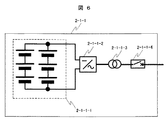
次に風力発電所を構成する蓄電システム2について説明する。蓄電システム2は、2台以上の蓄電装置2−1−2,2−1−2,2−1−3によって構成される。個々の蓄電装置について、図1と図6を用いて説明する。
Next, the
蓄電装置2−1−1は、複数の二次電池2−1−1−1と電力変換器2−1−1−2,変圧器2−1−1−3,遮断器2−1−1−4等で構成される。二次電池2−1−1−1は必要な容量,電圧に応じて単位2次電池セルの直列接続,並列接続の組み合わせで構成する。電力変換器2−1−1−2は、図示していないが電力変換器制御のためのコントローラを内蔵している。蓄電装置は電力変換器2−1−1−2を制御することにより、図1に示した上位コントローラからの充放電電力指令PBC1,PBC2,PBC3に追従するように充放電電力PB1,PB2,PB3を制御する。また上位コントローラ3から回復充電指令を受信した場合は、充放電電力指令には追従せずに、電力変換器2−1−1−2を制御することで蓄電池の回復充電を行う。また各蓄電装置2−1−1,2−1−2,2−1−3は二次電池の充電率SOC1,SOC2,SOC3及び充放電電力PB1,PB2,PB3を測定し、上位コントローラ3に送信する。電力計7で測定された蓄電システム2の充放電電力PBと、各蓄電装置が測定した充放電電力PB1,PB2,PB3には、(数3)に示す関係式が成り立つ。
The power storage device 2-1-1 includes a plurality of secondary batteries 2-1-1-1, a power converter 2-1-1-2, a transformer 2-1-1-3, and a circuit breaker 2-1-1. -4 etc. The secondary battery 2-1-1-1 is configured by a combination of series connection and parallel connection of unit secondary battery cells according to necessary capacity and voltage. The power converter 2-1-1-2 has a built-in controller for controlling the power converter, although not shown. The power storage device controls charging / discharging power PB1, PB2, PB3 so as to follow charging / discharging power commands PBC1, PBC2, PBC3 from the host controller shown in FIG. To control. Moreover, when the recovery charge command is received from the
(数3)PB=PB1+PB2+PB3−(補正量2)
補正量2は電力計7と各蓄電装置2−1−1,2−1−2,2−1−3間の配電線等の損失を表す。また図1に示した蓄電システム2は蓄電装置3台で構成されるが、本発明を実現するには2台以上の蓄電装置で構成すればよく、蓄電装置の台数は3台に限定されるものではない。
(Expression 3) PB = PB1 + PB2 + PB3- (correction amount 2)
A
本発明においては二次電池2−1−1−1として鉛蓄電池を利用する。本発明に使用する二次電池2−1−1−1を備えた蓄電装置は風力発電システム1の発電電力変動に対して、充放電を行うことで発電所の出力電力PSの変動緩和を行うことを目的とする。このため二次電池2−1−1−1は部分的な放電状態で放置、あるいは運用する期間が大部分を占める。鉛蓄電池は放電状態で放置すると鉛蓄電池の電極の表面に硫酸鉛が結晶化する。鉛蓄電池電極表面の硫酸鉛結晶は、結晶後早い段階で充電を行うことで、再び電解液に溶け出す。しかしながら鉛蓄電池を放電状態で長期間放置すると、鉛蓄電池電極表面上に硬い硫酸鉛結晶が出現する、いわゆるサルフェーション現象が発生する。サルフェーション化した硬い硫酸鉛結晶は溶解度が低いため、再び充放電のサイクルで電解液に溶け出しにくい。このためサルフェーションが発生すると鉛蓄電池の充放電容量が低下し、鉛蓄電池の寿命が短くなる。本発明のように鉛蓄電池を電力変動緩和を目的として使用する際は、サルフェーション防止のため回復充電(あるいはリセット充電)を行うのが一般的である。回復充電とは2週間に1回程度鉛蓄電池を満充電状態、あるいは過充電状態にすることで、サルフェーションの発生を防止することである。回復充電には1回でおよそ6〜8時間の期間が必要であり、また回復充電中は一定電流・一定電圧充電方式によって充電を行う。このため回復充電中の蓄電装置は風力発電所の変動緩和のための充放電を行うことができない。風力発電所の変動緩和効果を維持したまま回復充電を行うことができれば、風力発電システム1の運転期間が増大し、自然エネルギーの有効利用につながる。以下で本発明の回復充電の方法について説明する。
In the present invention, a lead storage battery is used as the secondary battery 2-1-1-1. The power storage device including the secondary battery 2-1-1-1 used in the present invention performs fluctuation relaxation of the output power PS of the power plant by charging and discharging the generated power fluctuation of the wind
本発明の風力発電所の運転方法について図7を用いて説明する。図7は風力発電所の出力電力の時系列変化を示したものである。図7(a)は風力発電システム1の発電電力PWと風力発電所の出力電力PSを示したものである。風力発電システム1の大きく変動する発電電力に対して蓄電装置2が充放電することにより、風力発電所出力電力PSの電力変動を緩和する。各蓄電装置2−1−1,2−1−2,2−1−3の充放電電力の時系列変化を示したものが図7(b),図7(c),図7(d)である。
The operation method of the wind power plant of this invention is demonstrated using FIG. FIG. 7 shows a time-series change in the output power of the wind power plant. FIG. 7A shows the generated power PW of the wind
時刻3[hour]以前では3つの蓄電装置がそれぞれ変動緩和に必要な充放電電力を均等に分担する。時刻3[hour]において蓄電装置2−1−1が上位コントローラ3より回復充電指令を受信し、回復充電モードに移行する。回復充電中においては、蓄電装置2−1−1は変動緩和のための充放電は行わずに一定電流・一定電圧の充電を行う。このため非回復充電状態中にある他の蓄電装置2−1−2,2−1−3は、2台で風力発電システムの電力変動を緩和し、かつ回復充電による電力変動も緩和するように充放電を行う。
Prior to time 3 [hour], the three power storage devices share the charge / discharge power required for mitigating fluctuations equally. At time 3 [hour], the power storage device 2-1-1 receives the recovery charge command from the
時刻5[hour]以降は風力発電システム1の周辺風速の低下等により、風力発電システム1の発電電力PWがほぼ0になった状況を示している。風力発電システム1の発電電力PWが0の際は、回復充電状態の蓄電装置2−1−1に対して、非回復充電状態中にある蓄電装置2−1−2,2−1−3が放電動作を行い、回復充電に必要な電力を供給する。このように回復充電に必要な電力を他の蓄電装置から供給することにより、風力発電システム1の周辺の風速に依存せずに、確実に回復充電を行うことが可能となる。なお回復充電状態の蓄電装置2−1−1に対して非回復充電状態の蓄電装置2−1−2,2−1−3が電力を供給する場合であっても、蓄電装置2−1−2,2−1−3の充放電指令PBC2,PBC3を上位コントローラ3が作成する点は、回復充電状態の電池が有る無しに関わらず同じである。
After the time 5 [hour], the generated power PW of the wind
図8は各蓄電装置2−1−1,2−1−2,2−1−3の回復充電のタイミングを示したものである。蓄電装置の回復充電モードは2週間に1回の頻度で発生する。各蓄電装置は1台ずつ順番に回復運転状態に移行する。1台の蓄電装置の回復充電が終了した後は、次の蓄電装置が回復充電を行う。このような回復充電のパターンを用いることで、2週間に1回の頻度で確実に蓄電装置が回復充電を実施できる。なお図8では同時に回復充電を行っている蓄電装置は1台のみであるが、蓄電装置が多数ある場合は、同時に複数台の蓄電装置が回復充電を実施しても本発明の効果が得られる。 FIG. 8 shows the timing of recovery charging of each power storage device 2-1-1, 2-1-2, 2-1-3. The recovery charge mode of the power storage device occurs once every two weeks. Each power storage device shifts to the recovery operation state one by one. After recovery charging of one power storage device is completed, the next power storage device performs recovery charging. By using such a recovery charging pattern, the power storage device can reliably perform recovery charging at a frequency of once every two weeks. In FIG. 8, only one power storage device is performing recovery charging at the same time. However, when there are a large number of power storage devices, the effect of the present invention can be obtained even if a plurality of power storage devices perform recovery charging at the same time. .
図9は本発明の回復充電中において、大きな電力変動が発生した場合の運転方法について説明したものである。図9は風力発電所の出力電力の時系列変化を示したものである。図9(a)が風力発電システム1の発電電力PWと風力発電所の出力電力PSを示したものである。風力発電システム1の発電電力PWに対して蓄電システム2が充放電を行うことにより、風力発電所の発電電力PSの変動が緩和される。図9(b),図9(c),図9(d)は各蓄電装置2−1−1,2−1−2,2−1−3の充放電電力を示したものである。
FIG. 9 illustrates an operation method when a large power fluctuation occurs during the recovery charge of the present invention. FIG. 9 shows the time series change of the output power of the wind power plant. FIG. 9A shows the generated power PW of the wind
図9(b)に示した蓄電装置2−1−1は時刻2[hour]から回復充電を行っているため、これ以降は蓄電装置2−1−2と蓄電装置2−1−3が変動緩和のための充放電を行う。回復充電前に比べて変動緩和に寄与できる蓄電装置の台数が減少したため、蓄電システム2の変動緩和能力は低下している。このため図9(a)の時刻4.5[hour]前後に発生した大きな風力発電システム1の電力変動に対しては、蓄電装置2台のみでは対応できない。このような大きな電力変動が発生した際には、回復充電中であった蓄電装置2−1−1は、一時的に回復充電を停止し変動緩和のための充放電を行う。風力発電システム1の電力変動の大きさが所定値以下に収まり、かつ一定時間経過したのち蓄電装置2−1−1は回復充電を再開する。このように風力発電システム1の発電電力PWの変動が所定の値より大きな事象に対して、回復充電中の蓄電装置が一時的に回復充電を停止することで、回復充電中であっても蓄電システム2全体の変動緩和能力を維持できる。また風力発電システム1の発電電力PWの変動が所定値以下に収まったのち、再度回復充電をおこなうことで、蓄電装置の回復充電を確実に行うことができる。
Since the power storage device 2-1-1 illustrated in FIG. 9B is performing recovery charging from time 2 [hour], the power storage device 2-1-2 and the power storage device 2-1-3 vary thereafter. Charge and discharge for relaxation. Since the number of power storage devices that can contribute to fluctuation mitigation is reduced compared to before recovery charging, the fluctuation mitigation ability of the
図10は本発明の風力発電所の動作を実現する上位コントローラ3の構成である。上位コントローラ3は風力発電所出力電力指令演算部3−1において、風力発電システム1の発電電力検出値PWから、例えば一次遅れフィルタ等を用いて変動緩和後の風力発電所の出力電力指令PS*を作成する。上位コントローラ3は減算器3−2において、風力発電所出力電力指令PS*と発電電力検出値PWの差分と損失を補正する補正量1から、蓄電システム2が充放電すべき充放電電力指令PB*を作成する。なお補正量1は、(数1)に従って求められる。充放電電力指令分配部3−3では、各蓄電装置の充放電電力指令を作成する。また回復充電指令演算部3−4において、各蓄電装置の回復充電のタイミングが、例えば図8のように決定される。風車発電電力制限指令演算部3−5では、風力発電システム1の発電電力制限指令PLC0を演算する。変動量演算部3−6においては、風力発電システム1の発電電力PWの変動量を演算しており、図9(a)のように変動量が所定値より大きくなった場合には、回復充電指令を一時的に解除するため、回復充電指令の送信を停止する。
FIG. 10 shows the configuration of the
充放電電力指令分配部3−3の動作について図11を用いて詳細に説明する。充放電電力指令分配部3−3では、蓄電システム2の充放電電力指令から回復充電中蓄電装置の充放電電力(本実施例ではPBC1)を減算し、さらに損失を補正する補正量2を加えることで、非回復充電状態の蓄電装置が出力する充放電電力指令PB0*を作成する。なお補正量2は(数3)から求められる。PB0*は非回復充電状態の蓄電装置の台数で除算され、各蓄電装置の充放電電力指令の中間値PBC11,PBC12,PBC13を作成する。さらに充放電電力指令の中間値PBC11,PBC12,PBC13に各蓄電装置のSOCを補正するための充放電電力指令PBSOC1,PBSOC2,PBSOC3を足しこむことで、各蓄電装置2−1−1,2−1−2,2−1−3の充放電電力指令PBC1,PBC2,PBC3が求められる。なおSOC補正のための充放電電力指令PBSOC1,PBSOC2,PBSOC3は、例えば(数4)に従って演算される。
The operation of the charge / discharge power command distribution unit 3-3 will be described in detail with reference to FIG. The charge / discharge power command distribution unit 3-3 subtracts the charge / discharge power (PBC1 in this embodiment) of the power storage device during recovery charging from the charge / discharge power command of the
(数4)PBSOCi=Kp×(SOCTi−SOCi)、i=1,2,3
ここでKpは比例係数、SOCTiは各蓄電装置の充電率目標値、SOCiは各蓄電装置の充電率を表す。上位コントローラは以上で説明した演算手段を用いることにより、風力発電所の出力電力PSの変動を緩和したまま、蓄電システム2の回復充電を可能とする。
(Expression 4) PBSOCi = Kp × (SOCTi−SOCi), i = 1, 2, 3
Here, Kp represents a proportional coefficient, SOCTi represents a charging rate target value of each power storage device, and SOCi represents a charging rate of each power storage device. The host controller uses the computing means described above to enable recovery charging of the
なお図1においては、蓄電システム2を構成する各蓄電装置2−1−1,2−1−2,2−1−3が、風力発電所の連系変圧器4の基に集中して配置されるが、本発明が効果を発揮するためには蓄電装置が一箇所に集中して設置される必要は無い。図12に示すように各蓄電装置2−1−1,2−1−2,2−1−3が、風力発電システム1と離れた場所に分散して設置しても本発明の効果は発揮される。また風力発電システム1の連系点と蓄電装置2−1−1,2−1−2,2−1−3の連系点の間に、一般家庭や産業設備等の負荷13−1が連系しても効果は同じである。同様に各蓄電装置2−1−1,2−1−2,2−1−3の間に負荷13−2が連系しても、本発明の効果は発揮される。
In FIG. 1, each power storage device 2-1-1, 2-1-2, 2-1-3 configuring the
図12に示すように各蓄電装置が分散されて設置された場合には、各蓄電装置2−1−1,2−1−2,2−1−3の発電電力測定値PB1,PB2,PB3及び、各蓄電装置2−1−1,2−1−2,2−1−3の充放電電力指令PBC1,PBC2,PBC3,回復充電指令は、通信手段15を介して上位コントローラ3と送受信される。通信手段は有線のLAN,WANあるいは無線通信により実現される。風力発電システム1の発電電力PW、および風力発電システム1の発電電力制限指令PLC0も同様に通信手段15を介して上位コントローラ3に送受信される。図12のように各蓄電装置が分散されて設置された場合には、上位コントローラ3は(数5)に従って風力発電所の出力電力PSを演算する。
When each power storage device is distributed and installed as shown in FIG. 12, the generated power measured values PB1, PB2, PB3 of each power storage device 2-1-1, 2-1-2, 2-1-3. The charge / discharge power commands PBC1, PBC2, PBC3 and the recovery charge command of each power storage device 2-1-1, 2-1-2, 2-1-3 are transmitted to and received from the
(数5)PS=PW+PB1+PB2+PB3
上位コントローラ3は(数5)で演算されるPSに従って、風力発電所の発電電力PSの変動が緩和されるよう、各蓄電装置2−1−1,2−1−2,2−1−3の充放電電力指令PBC1,PBC2,PBC3を決定する。
(Equation 5) PS = PW + PB1 + PB2 + PB3
In accordance with the PS calculated by (Equation 5), the
以上で説明したように本発明では風力発電システムに対して複数の蓄電装置を設け、蓄電装置の一部が回復充電を実施し、かつ残りの非回復充電状態の蓄電装置が変動緩和のための充放電を実施する。また回復充電のための電力を非回復充電状態の蓄電装置が供給する運転モードを持つ。本発明の運転方法を用いることで、蓄電装置は風の強さに影響を受けず、確実に定期的回復充電を実施することが可能となる。定期的な回復充電により、蓄電池を構成する二次電池の長寿命化を可能とし、結果的に風力発電所の長期間運用により自然エネルギーを有効に活用できる。また回復充電中であっても変動緩和効果を維持できることから、風力発電システムの運転を停止することなく、自然エネルギーを有効に利用することが可能となる。 As described above, in the present invention, a plurality of power storage devices are provided for a wind power generation system, a part of the power storage device performs recovery charging, and the remaining power storage devices in a non-recovery charged state are for mitigating fluctuations. Perform charge / discharge. In addition, there is an operation mode in which power for recovery charging is supplied by the power storage device in the non-recovery charge state. By using the operation method of the present invention, the power storage device is not affected by the strength of the wind, and it is possible to reliably perform periodic recovery charging. Periodic recovery charging makes it possible to extend the life of the secondary battery that constitutes the storage battery, and as a result, natural energy can be effectively utilized by long-term operation of the wind power plant. In addition, since the fluctuation mitigation effect can be maintained even during recovery charging, natural energy can be used effectively without stopping the operation of the wind power generation system.
本発明の第2の実施例について図13を用いて説明する。本実施例の風力発電所の基本的な構成は実施例1と同様であるため、風力発電所の詳細な説明は省略する。本実施例の最も大きな特徴は、蓄電装置2の回復充電中において、風力発電システム1の発電電力制限指令PLC0を、非回復充電状態の蓄電装置のみの蓄電システムで運用する場合のPLC0より小さく設定することである。
A second embodiment of the present invention will be described with reference to FIG. Since the basic configuration of the wind power plant of the present embodiment is the same as that of the first embodiment, detailed description of the wind power plant is omitted. The most significant feature of the present embodiment is that, during recovery charging of the
図13は本実施例の風力発電所の蓄電装置2の運転状態と、風力発電システム1の発電電力の時系列変化を示したものである。図13(a)は各蓄電装置2−1−1,2−1−2,2−1−3の運転状態の時系列変化を示したものであり、時刻T1から時刻T2の間は、各蓄電装置が順番に回復充電を行っている。回復充電の蓄電装置がある場合、変動緩和に利用できる蓄電装置の台数が減少するため、蓄電システム2の変動緩和能力が低下している。このため実施例1では風力発電システム1に大きな電力変動が発生した場合、回復充電中の蓄電装置が一時的に回復充電を停止し、変動緩和を行った。本実施例においては回復充電中において、風力発電システム1に発生する電力変動を抑制することで、非回復充電状態の蓄電装置のみで変動緩和を実現することを可能とする。具体的には図13(b)に示したように、回復充電状態の蓄電装置がある場合は、上位コントローラ3が風力発電システムの発電電力制限指令PLC0を、回復充電状態の蓄電装置が無い場合にくらべて小さな値に設定する。発電電力制限指令PLC0を小さな値に設定することで、風力発電システム1の大きな発電電力PWの出現が抑制され、結果的に風力発電システム1の大きな発電電力変動の発生も抑制される。
FIG. 13 shows the operating state of the
本実施例においては蓄電装置3台で構成されるので、回復充電状態においては蓄電装置2台で変動緩和が可能な電力変動値に、発電電力制限指令PLC0を設定する。このようにPLC0を設定することで図13(b)に示したように、蓄電装置2台で変動緩和ができない大きな発電電力変動の発生が抑制でき、回復充電中の蓄電装置は回復充電を行うことができる。また蓄電システム2の回復充電中に風力発電システム1の発電電力が発電電力制限指令PLC0により制限されるが、回復充電中に風力発電システム1を停止する場合よりもより大きな発電電力を得ることができる。
In the present embodiment, since it is configured by three power storage devices, the generated power limit command PLC0 is set to a power fluctuation value that can be reduced by two power storage devices in the recovery charge state. By setting PLC0 in this way, as shown in FIG. 13B, it is possible to suppress the occurrence of large generated power fluctuations that cannot be mitigated by two power storage devices, and the power storage device that is undergoing recovery charging performs recovery charging. be able to. Further, the generated power of the wind
以上で説明したように本発明においては回復充電中において風力発電システム1の発電電力制限指令PLC0を所定値以下に設定し、風力発電システム1の発電電力PWを所定値以下に抑制する。本発明の運転方法を用いることで、蓄電システム2が確実に回復充電を行うことができる。また蓄電システム2が回復充電中であっても風力発電システム1が発電運転を継続することが可能となり、風力発電システム1の発電運転を停止する場合にくらべ、より自然エネルギーを有効利用できる。
As described above, in the present invention, the generated power limit command PLC0 of the wind
本発明の第3の実施例について図14を用いて説明する。図14に示す本実施例の構成要素のうち、図1と番号が同じものは同一の構成要素を指し示すため、説明は省略する。本実施例の最も大きな特徴は、風力発電所が発電電力予測事業者10より発電電力予測値PPを受信し、発電電力予測値PPにもとづいて各蓄電装置の回復充電タイミングをスケジューリングする点である。
A third embodiment of the present invention will be described with reference to FIG. Of the constituent elements of the present embodiment shown in FIG. 14, those having the same numbers as those in FIG. The most significant feature of this embodiment is that the wind power plant receives the generated power prediction value PP from the generated power
発電電力予測事業者10は気象庁が配信する未来における風力発電システム周辺の風速予測値と、過去の気象データ,地形データから風力発電システムの将来における発電電力を予測する。なお発電電力の予測が可能な期間は、気象庁の予測値が配信される期間によって制限をされ、およそ50時間程度先までの発電電力予測が可能である。
The power
風力発電所は発電電力予測事業者10から発電電力の予測値を信号線、あるいは無線により受信する。風力発電所は、受信した発電電力予測値PPに基づいて、各蓄電装置2−1−1,2−1−2,2−1−3の回復充電のタイミングをスケジューリングする。図15は発電電力予測値PPと、回復充電のスケジューリングの関係を示したものである。蓄電装置が回復充電を行っている間は、回復充電中の蓄電装置は変動緩和のための充放電を行うことができない。このため回復充電中に風力発電システム1に大きな電力変動が発生した場合は、電力系統に対して大きな電力変動を放出する虞がある。蓄電装置の回復充電を効率的に行うためには、風力発電システム1の発電電力変動が小さな期間において、回復充電を行うことが望ましい。
The wind power plant receives the predicted value of the generated power from the generated power
本実施例では、図15(a)に示したように風力発電システムの発電電力予測値PPが所定値以下になる時刻T1を風力発電所が求める。風力発電システムの発電電力PWが小さい期間においては、発生しうる発電電力変動も小さいため、回復充電中において大きな発電電力変動が発生する確率も小さい。本発明では図15(b)に示したように、発電電力予測値PPが所定値より小さくなる期間(時刻T1以降)に回復充電を行うように、各蓄電装置2−1−1,2−1−2,2−1−3の回復充電のタイミングをスケジューリングする。上位コントローラ3は時刻T1に達した時点で、各蓄電装置2−1−1に回復充電指令を伝達する。各蓄電装置2−1−1,2−1−2,2−1−3は回復充電指令を受信した際は、各蓄電装置がそれぞれ一定電流・一定電圧方式によって回復充電を行う。なお図15では回復充電のスケジュールを風力発電電力の予測値PPが所定値以下になる期間で設定したが、風力発電電力予測値PPの変動率が所定値以下になる期間において回復充電をスケジュールしても、本発明の効果は同じである。
In the present embodiment, as shown in FIG. 15A, the wind power plant obtains a time T1 at which the generated power predicted value PP of the wind power generation system is equal to or less than a predetermined value. In the period when the generated power PW of the wind power generation system is small, the generated power fluctuation that can be generated is also small, so the probability that a large generated power fluctuation occurs during the recovery charge is also small. In the present invention, as shown in FIG. 15 (b), each power storage device 2-1-1-2-1 is configured to perform recovery charging in a period (after time T 1) in which the generated power predicted value PP is smaller than a predetermined value. The timing of recovery charging of 1-2 and 2-1-3 is scheduled. The
以上で説明したように、本実施例では風力発電システムの発電電力予測値にもとづいて、蓄電装置の回復充電を行う期間をスケジューリングする。本実施例によるスケジューリングにより、風力発電システムの発電電力変動が小さな期間に回復充電を行う確率が高まり、結果的に電力系統に流出する発電電力変動が小さくできる可能性が高まる。また実施例2に示したように風力発電システムの発電電力制限指令を使用する必要がなくなるため、風車発電電力制限による自然エネルギーの損失を防止でき、自然エネルギーをより有効に活用できる。 As described above, in this embodiment, the period for performing the recovery charge of the power storage device is scheduled based on the predicted power generation value of the wind power generation system. The scheduling according to the present embodiment increases the probability of performing recovery charging in a period in which the generated power fluctuation of the wind power generation system is small, and consequently increases the possibility that the generated power fluctuation flowing out to the power system can be reduced. Moreover, since it becomes unnecessary to use the generated power restriction command of the wind power generation system as shown in the second embodiment, the loss of natural energy due to the windmill power generation restriction can be prevented, and the natural energy can be used more effectively.
本発明の第4の実施例について図16,図17を用いて説明する。図16に示す本実施例の構成要素のうち、図1と番号が同じものは同一の構成要素を指し示すため、説明は省略する。本実施例の最も大きな特徴は、蓄電システム2の回復充電のための電力を、補助発電機から供給する点である。以下、本実施例の詳細について説明する。
A fourth embodiment of the present invention will be described with reference to FIGS. Among the constituent elements of the present embodiment shown in FIG. 16, those having the same numbers as those in FIG. The most significant feature of this embodiment is that power for recovery charging of the
本実施例の風力発電所は、風力発電システム1の他に、補助発電機であるガスエンジン発電機11を構成要素に持つ。ガスエンジン発電機11は、ガスエンジンと同期発電機で構成される。ガスエンジン発電機11は、天然ガスや液化石油ガス(LPG)、水素ガス等を燃料に同期発電機を回転させ、発電電力を外部に送電することが可能である。ガスエンジン発電機の発電電力PGEは電力計12によって計測される。またガスエンジン発電機11は、上位コントローラからの発電電力指令PGECに追従するように発電電力PGEを制御できる発電システムである。
In addition to the wind
従来の風力発電所に併設されるガスエンジン発電機11は、風力発電所の連系変圧器4の突入電流を抑制するために使用される。つまり遮断器9が開状態において、ガスエンジン発電機11を運転し、連系変圧器4を2次側から励磁した後、遮断器9を閉状態にする。このような運転方法を採用することで、連系変圧器4が電力系統5に連系する際の突入電流を抑制できる。ガスエンジン発電機11による発電電力は、風力のような再生可能エネルギーを利用したものではないため、風力発電所の発電運転時においては、ガスエンジン発電機11を停止しておくことが一般的である。
The
本実施例の風力発電所においては、風力発電所の発電運転時であってもガスエンジン発電機11を運転し、蓄電システム2の回復充電に利用する。風力発電所は電力系統運用者からの要請により、風力発電システムを系統から切り離す、あるいは電力系統へ出力する電力を所定値以下に制限する期間が必要となる場合がある。この期間を開列期間と呼ぶ。風力発電所の開列期間は、電力系統を構成する火力発電所の稼働率が低下する夜間に発生する。これは電力系統の電力需給バランスを補償する役割を担う火力発電所の稼働率が低下した際、風力発電所から大きな電力変動が発生すると、電力系統が電力変動を吸収することが困難なためである。このため開列期間においては、風力発電所の発電電力を所定値以下(例えば風力発電所定格の2%以下)に抑制する、あるいは風力発電所を電力系統5から切り離す必要がある。本実施例の風力発電所は、開列期間中において蓄電システム2の回復充電を行う。
In the wind power plant of the present embodiment, the
本実施例の風力発電所の運転方法について図17を用いて説明する。図17は風力発電所の各構成要素の運転状態、発電電力を時系列に表示したものである。図17に示した例では、風力発電所の開列期間は時刻T1から時刻T3の期間に発生する。開列期間においては図17(b)に示すように、風力発電所の出力電力PSを、所定値以下(2%以下=0.02[PU]以下)に制限する。このため従来の制御方式においては、開列期間中に風力発電システム1が発電を行うのに十分に大きな風速があっても、風力発電システム1の発電電力制限機能により風のエネルギーの利用を制限するのが一般的である。
The operation method of the wind power plant of a present Example is demonstrated using FIG. FIG. 17 shows the operating state and generated power of each component of the wind power plant in time series. In the example shown in FIG. 17, the open period of the wind power plant occurs in the period from time T1 to time T3. In the open period, as shown in FIG. 17B, the output power PS of the wind power plant is limited to a predetermined value or less (2% or less = 0.02 [PU] or less). For this reason, in the conventional control method, even if there is a wind speed that is large enough for the wind
以下、本実施例の風力発電所の運転方法について詳細に説明する。風力発電所の上位コントローラ3は電力系統運用者から、開列期間の開始時刻T1と開列終了時刻T2について連絡を受ける。上位コントローラ3は、図17(C)に示すように開列期間開始時刻T1の直前から、風力発電システム1の発電電力制限指令PLC0を所定の変化率で低下させる。発電電力制限指令PLC0は、開列期間開始時刻T1において2%以下になるように設定する。風力発電システム1は、発電電力をPLC0以下に制限するため、風力発電所の出力電力PSは、開列期間開始時刻T1において2%以下に制限される。上位コントローラ3は開列期間中において、図17(d)に示すように蓄電システム2に対して回復充電指令を送信する。各蓄電装置2−1−1,2−1−2,2−1−3は上位コントローラ3からの回復充電指令を受信後、それぞれ一定電流・一定電圧の充電方式により回復充電を行う。
Hereinafter, the operation method of the wind power plant of a present Example is demonstrated in detail. The
本実施例では図17(a)に示すように開列期間中の前半部T1〜T2において、風力発電システム1が発電を行うのに十分な風速がある例を示している。開列期間中T1〜T2のように風力発電システム1が発電可能な際は、蓄電システム2の回復充電に必要な電力を風力発電システム1が供給する。具体的には図17(c)に示すように、上位コントローラ3が蓄電システム2の充電電力に応じて風力発電システム1の発電電力制限指令PLC0を変化させる。上位コントローラ3は発電電力制限指令PLC0を(数6)に従って演算する。
In the present embodiment, as shown in FIG. 17A, an example in which there is a wind speed sufficient for the wind
(数6)PLC0=−PB+(補正量3)
(数6)中の補正量3は、風力発電所の出力電力PSが負値になるのを防止する(風力発電所が充電状態になるのを防止する)ための値であり、風力発電所定格値の1%程度の固定値であればよい。このような制御手法を用いることにより、風力発電システム1が回復充電に必要な充電電力を供給し、かつ風力発電所の出力電力PSを所定値以下に制限することができる。
(Equation 6) PLC0 = −PB + (correction amount 3)
The
一方、図17(a)に示すように開列期間中の時刻T2,T3においては風速が減少しており、風力発電システム1が発電することができない、あるいは蓄電システム2の回復充電のための電力を供給するには発電電力が不足する。本発明では風速の小さな開列期間T2〜T3において、ガスエンジン発電機11から、回復充電のための電力を供給する。具体的には、図17(f)に示すように、上コントローラ3が蓄電システム2の充電電力に応じて、ガスエンジン発電機11の発電電力指令PGECを変化させる。ガスエンジン発電機11は、発電電力指令PGECに追従するように発電電力を制御する。上位コントローラ3は発電電力指令PGECを(数7)に従って演算する。
On the other hand, as shown in FIG. 17A, the wind speed decreases at times T2 and T3 during the open period, and the wind
(数7)PGEC=−PB−PW+(補正量4)
(数7)中の補正量4は、(数6)と同様に風力発電所定格値の1%程度の固定値である。この制御手法を用いることにより、ガスエンジン発電機11が回復充電に必要な充電電力を供給し、かつ風力発電所の出力電力PSを所定値以下に制限することができる。
(Expression 7) PGEC = −PB−PW + (correction amount 4)
The
蓄電システム2の回復充電が完了した後は、ガスエンジン発電機11は運転を停止する。また開列期間が終了した時刻T3以降は、上位コントローラ3は発電電力制限指令PLC0を所定の変化率で変化させ、風力発電システム1は風速に応じて発電運転する。
After the recovery charging of the
なお本実施例においては補助発電機として、気体燃料を用いたガスエンジン発電機11を用いた例を示した。補助発電機としてガスエンジン発電機11の代わりに、ガソリン等の液体燃料を利用したエンジン発電機、あるいは太陽光発電装置、あるいは燃料電池等を用いても本発明の効果は同じである。
In addition, in the present Example, the example using the
以上で説明したように、本実施例では風力発電所の開列期間中において、風力発電システム1の発電電力制限制御により蓄電システム2の回復充電を行いつつ、風力発電所の出力電力PSを所定値以下に制限することが可能となる。また蓄電システム2の回復充電中において風力発電システム1の発電電力が不足した場合は、補助発電機が電力を供給することで、蓄電システム2が回復充電を完遂することを可能とする。この運転方式により回復充電中であっても、風力発電システム1の発電電力を回復充電に利用できるため、自然エネルギーの有効利用に繋がる。また蓄電システム2の回復充電を確実に完遂することが可能となり、蓄電システム2を構成する二次電池の長寿命化を可能とし、結果的に風力発電所の長期間運用により自然エネルギーを有効に活用できる。
As described above, in this embodiment, during the open period of the wind power plant, the output power PS of the wind power plant is set to a predetermined value while performing the recovery charging of the
本発明は太陽光発電システムや波力発電システムのように発電電力が変動する電源に、二次電池を併設した発電システムに適用可能である。 The present invention can be applied to a power generation system in which a secondary battery is provided in addition to a power source whose generated power fluctuates, such as a solar power generation system or a wave power generation system.
また消費電力が変動する負荷に、変動緩和のため二次電池を併設した蓄電システムに対しても適用可能である。 Further, the present invention can be applied to a power storage system in which a secondary battery is provided in combination with a load whose power consumption fluctuates to reduce fluctuation.
1 風力発電システム
1−1−1,1−1−2,1−1−3 風力発電装置
1−2 SCADA
1−1−1−1,1−1−1a−1,1−1−1b−1,1−1−1c−1 ブレード
1−1−1−2,1−1−1a−2,1−1−1b−2,1−1−1c−2 風速計
1−1−1−3,1−1−1a−3,1−1−1b−3,1−1−1c−3 変速ギア
1−1−1−4 直流励磁同期発電機
1−1−1a−4 交流励磁同期発電機
1−1−1b−4 永久磁石発電機あるいは誘導発電機
1−1−1c−4 誘導発電機
1−1−1−5,1−1−1−6,1−1−1a−6,1−1−1b−6,2−1−1−2 電力変換器
1−1−1−7,1−1−1a−7,1−1−1b−7,1−1−1c−7,2−1−1−3,4,14−1,14−2 連系変圧器
1−1−1−8,1−1−1a−8,1−1−1b−8,1−1−1c−8,2−1−1−4,9 遮断器
1−1−1−9 励磁装置
1−1−1−10,1−1−1a−10,1−1−1b−10,1−1−1c−10 ナセル
2 蓄電システム
2−1−1,2−1−2,2−2−3 蓄電装置
2−1−1−1 二次電池
3 上位コントローラ
3−1 風力発電所出力電力指令演算部
3−2 減算器
3−3 充放電電力指令分配部
3−3−1,3−7 補正量演算部
3−3−2 SOC補正充放電電力演算部
3−3−3−1,3−3−3−2,3−3−3−3,3−8 加算器
3−3−4−1,3−3−4−2,3−3−4−3 選択演算部
3−4 回復充電指令演算部
3−5 風車制限指令演算部
3−6 変動量演算部
5 電力系統
6,7,8,12 電力計
10 発電電力予測事業者
11 ガスエンジン発電機
13−1,13−2 負荷
15 通信手段
DESCRIPTION OF
1-1-1-1, 1-1-1a-1, 1-1-1b-1, 1-1-1c-1 Blade 1-1-1-2, 1-1-1a-2, 1- 1-1b-2, 1-1-1c-2 Anemometer 1-1-1-3, 1-1-1a-3, 1-1-1b-3, 1-1-1c-3 1-1-4 DC excitation synchronous generator 1-1-1a-4 AC excitation synchronous generator 1-1-1b-4 Permanent magnet generator or induction generator 1-1-1c-4 Induction generator 1-1 -1-5, 1-1-1-6, 1-1-1a-6, 1-1-1b-6, 2-1-1-2 power converter 1-1-1-7, 1-1 -1a-7, 1-1-1b-7, 1-1-1c-7, 2-1-1-3, 4, 14-1, 14-2 interconnection transformer 1-1-1-8, 1-1-1a-8, 1-1-1b-8, 1-1-1c-8, 2-1-1-4 9 Circuit breaker 1-1-1-9 Exciting device 1-1-1-10, 1-1-1a-10, 1-1-1b-10, 1-1-1c-10 Nacelle 2 Power storage system 2-1 -1, 2-1-2, 2-2-3 Power storage device 2-1-1-1 Secondary battery 3 Host controller 3-1 Wind power plant output power command calculation unit 3-2 Subtractor 3-3 Charging / discharging Power command distribution unit 3-3-1, 3-7 Correction amount calculation unit 3-3-2 SOC correction charge / discharge power calculation unit 3-3-1-1, 3-3-3-2, 3-3-3 -3, 3-8 Adder 3-3-4-1, 3-34-2, 3-3-4-3 Selection calculation unit 3-4 Recovery charge command calculation unit 3-5 Windmill limit command calculation unit 3-6 Fluctuation amount calculation unit 5 Electric power system 6, 7, 8, 12 Wattmeter 10 Electric power generation prediction business operator 11 Gas engine generators 13-1, 13-2 Load 15 Communication means
Claims (9)
前記風力発電システムは1台以上の風力発電装置を有し、
前記蓄電システムは2台以上の蓄電装置を有し、
該複数の蓄電装置は構成要素に2次電池を備えて、電力系統に接続された風力発電所において、
該風力発電所は風力発電システムの発電電力を検出する手段と、
前記複数の蓄電装置の充放電電力の合計値を検出する手段と、
前記発電電力と前記充放電電力を受信するコントローラを備え、
該コントローラは、
前記風力発電所の電力変動を緩和する前記蓄電システムの充放電電力指令を演算する手段と、
前記複数の蓄電装置のうち1台以上が回復充電状態にある時に、前記複数の蓄電装置のうち非回復充電状態にある前記蓄電装置によって前記風力発電所の出力電力の変動を緩和し、かつ回復充電による電力変動も緩和するように、前記充放電電力指令から回復充電中の充放電電力を減算して、前記複数の蓄電装置のうち非回復充電状態にある前記蓄電装置に対する充放電電力指令を演算する手段と、
前記風力発電システムの発電電力の変動が所定値より大きかった場合には、回復充電状態にある前記蓄電装置が回復充電を停止し、前記風力発電所の出力電力の変動を緩和するように充放電電力を調整する手段を備えることを特徴とする風力発電所。 Equipped with wind power generation system and power storage system,
The wind power generation system has one or more wind power generation devices,
The power storage system has two or more power storage devices,
The plurality of power storage devices include a secondary battery as a component, and in a wind power plant connected to an electric power system,
The wind power plant comprises means for detecting the power generated by the wind power generation system;
Means for detecting a total value of charge / discharge power of the plurality of power storage devices;
A controller for receiving the generated power and the charge / discharge power;
The controller,
Means for calculating a charge / discharge power command of the power storage system for mitigating power fluctuations of the wind power plant ;
When more than one of the plurality of power storage device is in a recovery charging state, to mitigate variations in the output power of the wind power plant by the power storage device in a non-recovery charging state of the previous SL plurality of power storage devices, and Charge / discharge power command for the power storage device in a non-recovery charge state among the plurality of power storage devices by subtracting charge / discharge power during recovery charge from the charge / discharge power command so as to reduce power fluctuation due to recovery charge It means for calculating a
When the fluctuation of the generated power of the wind power generation system is larger than a predetermined value, the power storage device in the recovery charge state stops the recovery charge and is charged / discharged so as to reduce the fluctuation of the output power of the wind power plant A wind power plant comprising means for adjusting electric power.
前記複数の蓄電装置の充電率を検出する手段と、
前記複数の蓄電装置の充電率を検出する手段での検出値と前記複数の蓄電装置の充電率目標値との差に基づき前記充放電電力指令に加算する補正値を演算する手段と備えることを特徴とする風力発電所。 In the wind power plant of Claim 1,
Means for detecting a charging rate of the plurality of power storage devices;
And a means for calculating a correction value to be added to the charge / discharge power command based on a difference between a detected value at the means for detecting a charging rate of the plurality of power storage devices and a charging rate target value of the plurality of power storage devices. A characteristic wind power plant.
前記コントローラは、前記風力発電システムの発電電力制限指令演算部を備え、
前記発電電力制限指令演算部は、前記複数の蓄電装置の少なくとも1台以上が回復充電状態にある場合には、前記風力発電システムの発電電力制限値を、前記蓄電システムに回復充電状態の蓄電装置が無い状態の発電電力制限値より小さな値に設定することを特徴とする風力発電所。 In the wind power plant of Claim 1,
The controller includes a generated power limit command calculation unit of the wind power generation system,
When at least one of the plurality of power storage devices is in a recovery charge state, the power generation power limit command calculation unit is configured to supply a power generation limit value of the wind power generation system to the power storage system in a recovery charge state. A wind power plant characterized in that it is set to a value smaller than the generated power limit value in a state where there is no power.
前記風力発電システムは1台以上の風力発電装置を有し、
前記蓄電システムは2台以上の蓄電装置を有し、
該複数の蓄電装置は構成要素に2次電池を備えて、電力系統に接続された風力発電所において、
該風力発電所は風力発電システムの発電電力を検出する手段と、
前記複数の蓄電装置の充放電電力の合計値を検出する手段と、
前記発電電力と前記充放電電力を受信するコントローラを備え、
該コントローラは前記風力発電所の電力変動を緩和する前記蓄電システムの充放電電力指令を演算する手段を備え、
前記複数の蓄電装置のうち1台以上が回復充電状態にある時に、前記風力発電所は前記風力発電所の出力電力の変動を緩和するように前記複数の蓄電装置のうち非回復充電状態にある前記蓄電装置の充放電電力を調整する手段と、
気象予測データに基づく風力発電システムの発電電力の予測値を入手する手段と、
前記風力発電所が前記風力発電システムの発電電力予測値に基づいて、前記蓄電システムの回復充電をスケジューリングする手段を備えることを特徴とする風力発電所。 Equipped with wind power generation system and power storage system,
The wind power generation system has one or more wind power generation devices,
The power storage system has two or more power storage devices,
The plurality of power storage devices include a secondary battery as a component, and in a wind power plant connected to an electric power system,
The wind power plant comprises means for detecting the power generated by the wind power generation system;
Means for detecting a total value of charge / discharge power of the plurality of power storage devices;
A controller for receiving the generated power and the charge / discharge power;
The controller includes means for calculating a charge / discharge power command of the power storage system that mitigates power fluctuations of the wind power plant,
When one or more of the plurality of power storage devices are in a recovery charge state, the wind power plant is in a non-recovery charge state among the plurality of power storage devices so as to mitigate fluctuations in output power of the wind power plant. Means for adjusting charge / discharge power of the power storage device;
Means for obtaining a predicted value of the generated power of the wind power generation system based on weather forecast data;
The wind power plant comprising: means for scheduling recovery charging of the power storage system based on a predicted power generation value of the wind power system.
前記風力発電システムは1台以上の風力発電装置を有し、
前記蓄電システムは2台以上の蓄電装置を有し、
該複数の蓄電装置は構成要素に2次電池を備えて、電力系統に接続された風力発電所において、
前記風力発電所は風力発電システムの発電電力を検出する手段と、
前記複数の蓄電装置の充放電電力の合計値を検出する手段と、
前記補助発電機の発電電力を検出する手段と、
前記風力発電所は前記発電電力と前記充放電電力と前記補助発電機の発電電力を受信するコントローラを備え、
該コントローラは前記風力発電所の電力変動を緩和する前記蓄電システムの充放電電力指令を演算する手段を備え、
該コントローラは前記補助発電機の発電電力指令を演算する手段と、
前記発電電力指令を前記補助発電機に送信する手段を備え、
前記風力発電所が開列期間中に、前記複数の蓄電装置のうち少なくとも1台以上の回復充電を行い、前記補助発電機が回復充電のための電力の一部、あるいは全てを供給する手段と、
前記風力発電所が開列期間中、前記風力発電所の出力電力が所定値以下となるように、前記風力発電システムの発電電力を調整する手段を備えることを特徴とする風力発電所。 A wind power generation system, a power storage system, and an auxiliary generator;
The wind power generation system has one or more wind power generation devices,
The power storage system has two or more power storage devices,
The plurality of power storage devices include a secondary battery as a component, and in a wind power plant connected to an electric power system,
The wind power plant has means for detecting the power generated by the wind power generation system;
Means for detecting a total value of charge / discharge power of the plurality of power storage devices;
Means for detecting the power generated by the auxiliary generator;
The wind power plant comprises a controller that receives the generated power, the charge / discharge power, and the generated power of the auxiliary generator,
The controller includes means for calculating a charge / discharge power command of the power storage system that mitigates power fluctuations of the wind power plant,
The controller calculates a power generation command of the auxiliary generator;
Means for transmitting the generated power command to the auxiliary generator;
The wind power plant during disconnection period, and at least one or more perform recovery charging, the auxiliary generator means for supplying a part or all of the power for recovery charging of the plurality of power storage devices,
A wind power plant comprising: means for adjusting the generated power of the wind power generation system so that the output power of the wind power plant is a predetermined value or less during the open period of the wind power plant.
前記風力発電システムの発電電力を調整する手段は、前記蓄電装置の回復充電に必要な電力に、前記風力発電所の出力電力が負値になるのを防止する補正量を加算した値を、前記風力発電システムの発電電力制限指令とすることを特徴とする風力発電所。 In the wind power plant according to claim 5 ,
Means for adjusting the generated power before Symbol wind power generation system, the power required for recovery charging of said power storage device, a value obtained by adding the correction amount to prevent the output power of the wind farm is a negative value, A wind power plant characterized in that the generated power limit command for the wind power generation system is used .
前記風力発電所が電力系統と連系する地点において前記風力発電所の出力電力を検出する手段とを備え、
前記風力発電所は前記風力発電システムの発電電力と前記充放電電力の合計値と前記風力発電所の出力電力を受信するコントローラを備え、
前記コントローラは前記風力発電システムの発電電力と前記充放電電力の合計値と前記風力発電所の出力電力から前記風力発電所の構成要素が発生する損失を演算する手段と、
前記蓄電システムに送信する充放電電力指令を演算する手段と、
前記充放電電力指令に対して前記損失を補正する手段とを備えることを特徴とする風力発電所。 In the wind power plant of Claim 1,
Means for detecting output power of the wind power plant at a point where the wind power plant is connected to a power system,
The wind power plant includes a controller that receives the generated power of the wind power generation system, the total value of the charge / discharge power, and the output power of the wind power plant,
The controller calculates a loss generated by a component of the wind power plant from a total value of the generated power of the wind power generation system and the charge / discharge power and output power of the wind power plant;
Means for calculating a charge / discharge power command to be transmitted to the power storage system;
A wind power plant comprising: means for correcting the loss with respect to the charge / discharge power command.
Priority Applications (3)
| Application Number | Priority Date | Filing Date | Title |
|---|---|---|---|
| JP2008105235A JP4759587B2 (en) | 2008-04-15 | 2008-04-15 | Wind farm |
| TW098111671A TWI388723B (en) | 2008-04-15 | 2009-04-08 | Wind power generation |
| EP09005262A EP2110549A3 (en) | 2008-04-15 | 2009-04-09 | Wind farm with battery storage |
Applications Claiming Priority (1)
| Application Number | Priority Date | Filing Date | Title |
|---|---|---|---|
| JP2008105235A JP4759587B2 (en) | 2008-04-15 | 2008-04-15 | Wind farm |
Publications (3)
| Publication Number | Publication Date |
|---|---|
| JP2009261076A JP2009261076A (en) | 2009-11-05 |
| JP2009261076A5 JP2009261076A5 (en) | 2010-06-03 |
| JP4759587B2 true JP4759587B2 (en) | 2011-08-31 |
Family
ID=41058836
Family Applications (1)
| Application Number | Title | Priority Date | Filing Date |
|---|---|---|---|
| JP2008105235A Expired - Fee Related JP4759587B2 (en) | 2008-04-15 | 2008-04-15 | Wind farm |
Country Status (3)
| Country | Link |
|---|---|
| EP (1) | EP2110549A3 (en) |
| JP (1) | JP4759587B2 (en) |
| TW (1) | TWI388723B (en) |
Families Citing this family (32)
| Publication number | Priority date | Publication date | Assignee | Title |
|---|---|---|---|---|
| JP4551921B2 (en) | 2007-09-27 | 2010-09-29 | 株式会社日立エンジニアリング・アンド・サービス | Wind power generation system with storage system |
| WO2010038667A1 (en) * | 2008-09-30 | 2010-04-08 | 日本碍子株式会社 | Method for controlling sodium-sulfur battery |
| EP2280167A3 (en) * | 2009-03-19 | 2011-12-07 | Hitachi Engineering & Services Co., Ltd. | Control method of electric power generation system utilizing renewable energy |
| KR101183751B1 (en) | 2009-09-10 | 2012-09-17 | 가부시키가이샤 히다치 엔지니어링 서비스 | Power storage device of power generation system and operation method thereof |
| JP5246806B2 (en) | 2009-11-16 | 2013-07-24 | 北川工業株式会社 | contact |
| JP5394217B2 (en) * | 2009-12-14 | 2014-01-22 | 株式会社日立パワーソリューションズ | Natural energy power plant with power storage |
| ES2372834B1 (en) * | 2009-12-17 | 2013-02-18 | Aroi Solar, S.L. | electrical energy storage system from renewable energy. |
| JP5672301B2 (en) * | 2010-06-30 | 2015-02-18 | 株式会社日立製作所 | Wind power generation system and control method for wind power generation system |
| CN101917021B (en) * | 2010-08-05 | 2013-04-10 | 国电南京自动化股份有限公司 | Derivative optimum-based power conversion and transient energy storage control method |
| JP2012039821A (en) * | 2010-08-10 | 2012-02-23 | Toshiba Corp | Power fluctuation relaxing device of power generating system and power fluctuation relaxing method |
| US8688281B2 (en) * | 2010-08-31 | 2014-04-01 | Vestas Wind Systems A/S | Optimization of energy storage device usage in wind energy applications |
| JP5509152B2 (en) | 2011-05-31 | 2014-06-04 | 株式会社日立製作所 | Power storage system |
| JP5767873B2 (en) * | 2011-06-28 | 2015-08-26 | 株式会社東芝 | Power storage device and power storage system |
| WO2013013174A2 (en) * | 2011-07-20 | 2013-01-24 | Inventus Holdings, Llc | Dispatchable renewable energy generation, control and storage facility |
| CN102280879B (en) * | 2011-08-01 | 2013-12-18 | 沈阳融华新能源电气有限公司 | Method and system for regulating power of large-scale energy storage power station of wind farm |
| JP2013106437A (en) * | 2011-11-14 | 2013-05-30 | Mitsubishi Heavy Ind Ltd | Wind power generation apparatus, method and program |
| JP2013219941A (en) * | 2012-04-10 | 2013-10-24 | Hitachi Power Solutions Co Ltd | Control method and control device of power generation system using renewable energy |
| CA2829247C (en) * | 2012-10-12 | 2017-03-14 | General Electric Company | System and method for wind power dispatch in a wind farm |
| CA2831361C (en) * | 2012-10-31 | 2016-10-04 | Hitachi, Ltd. | Power generation system, backup power supply, data center installation method, power generation system controller, power system, and power generation system operating method |
| JP6247039B2 (en) * | 2013-07-25 | 2017-12-13 | 電源開発株式会社 | Power storage device and charging / discharging method of power storage device |
| CN103560591A (en) * | 2013-10-11 | 2014-02-05 | 安徽启光能源科技研究院有限公司 | Optimizing method for output smoothness of mobile energy storage power station |
| US9915243B2 (en) * | 2014-02-24 | 2018-03-13 | General Electric Company | System and method for automatic generation control in wind farms |
| JP2016049008A (en) * | 2014-08-28 | 2016-04-07 | 新神戸電機株式会社 | Storage battery system, database and recording medium |
| JP6372291B2 (en) * | 2014-10-08 | 2018-08-15 | 株式会社明電舎 | Grid interconnection system and method for controlling grid interconnection system |
| WO2016167816A1 (en) * | 2015-04-11 | 2016-10-20 | Siemens Aktiengesellschaft | Dynamic wind turbine energy storage device |
| CN106159980B (en) | 2015-04-14 | 2020-08-04 | 通用电气公司 | Power generation system and energy management method |
| CN106300407B (en) | 2015-05-26 | 2020-03-17 | 通用电气公司 | Power generation system |
| US9797566B2 (en) | 2015-09-30 | 2017-10-24 | Chauvin Souvandy | Self-powered street light |
| CN106089579B (en) * | 2016-06-16 | 2019-08-16 | 三一重型能源装备有限公司 | The control method and system of wind power generating set |
| CN110008491A (en) * | 2018-11-27 | 2019-07-12 | 国网山东省电力公司电力科学研究院 | A kind of wind light mutual complementing power generation power output digital simulation method based on improvement probabilistic model |
| JP6921892B2 (en) * | 2019-04-22 | 2021-08-18 | シャープ株式会社 | Output control device, power generation system, output control method, control program, and recording medium |
| US20220349378A1 (en) * | 2021-04-29 | 2022-11-03 | RoadSense Advanced Technologies Ltd. | Road surface electrical generator and sensor |
Family Cites Families (9)
| Publication number | Priority date | Publication date | Assignee | Title |
|---|---|---|---|---|
| US4535252A (en) | 1983-04-29 | 1985-08-13 | Jacobs Wind Electric Company | Wind electric generation plant and system with improved alternator field excitation |
| US5083039B1 (en) | 1991-02-01 | 1999-11-16 | Zond Energy Systems Inc | Variable speed wind turbine |
| JP2001157382A (en) * | 1999-11-25 | 2001-06-08 | Nissin Electric Co Ltd | Method of operating batteries in power storage apparatus |
| JP2001157383A (en) * | 1999-11-25 | 2001-06-08 | Nissin Electric Co Ltd | Power storage device |
| DE10008028A1 (en) * | 2000-02-22 | 2001-09-06 | Oekotech Verwaltungs Gmbh | Wind power system has wind energy converter, device for storing electrical energy in storage medium and supply device for transferring storage medium to motor vehicle |
| JP2001286076A (en) * | 2000-03-31 | 2001-10-12 | Nissin Electric Co Ltd | Control method of system stabilization device |
| JP2002058175A (en) * | 2000-08-07 | 2002-02-22 | Japan Storage Battery Co Ltd | Independent power supply system |
| JP3978126B2 (en) * | 2002-12-05 | 2007-09-19 | 株式会社日立製作所 | Wind power generation system with secondary battery |
| JP4609156B2 (en) * | 2005-03-31 | 2011-01-12 | 株式会社明電舎 | Power storage device control device |
-
2008
- 2008-04-15 JP JP2008105235A patent/JP4759587B2/en not_active Expired - Fee Related
-
2009
- 2009-04-08 TW TW098111671A patent/TWI388723B/en active
- 2009-04-09 EP EP09005262A patent/EP2110549A3/en not_active Withdrawn
Also Published As
| Publication number | Publication date |
|---|---|
| EP2110549A3 (en) | 2011-03-02 |
| TW201007013A (en) | 2010-02-16 |
| EP2110549A2 (en) | 2009-10-21 |
| JP2009261076A (en) | 2009-11-05 |
| TWI388723B (en) | 2013-03-11 |
Similar Documents
| Publication | Publication Date | Title |
|---|---|---|
| JP4759587B2 (en) | Wind farm | |
| JP5042369B2 (en) | Power storage device for power generation system and method of operating power storage device | |
| US10283964B2 (en) | Predictive control for energy storage on a renewable energy system | |
| WO2018124221A1 (en) | Combined cycle power generation system | |
| JP4155674B2 (en) | Frequency control device for power system including secondary battery | |
| JP5055407B2 (en) | Control method of power generation system using renewable energy | |
| DK2573895T3 (en) | A method for operating a wind farm, the wind farm control unit and wind farm | |
| JP5167106B2 (en) | Wind power plant and its power generation control method | |
| JP5394217B2 (en) | Natural energy power plant with power storage | |
| JP5526079B2 (en) | Wind power generation system and method for adding wind power generator in wind power generation system | |
| EP2481923A1 (en) | Output control method and output control device for wind-powered electricity generating facility | |
| US20120265356A1 (en) | Power output leveling method and apparatus for wind turbine generating facility | |
| WO2012057307A1 (en) | Control device for power management | |
| US20220224145A1 (en) | Full dc voltage power backup system for wind turbine | |
| EP2280167A2 (en) | Control method of electric power generation system utilizing renewable energy | |
| WO2019193837A1 (en) | Power generating system and its control method | |
| JP5529028B2 (en) | Control method of sodium-sulfur battery | |
| RU95434U1 (en) | MULTIFUNCTIONAL ENERGY COMPLEX (IEC) | |
| KR101185636B1 (en) | Wind power plant | |
| Beltramin | State-of-the-art of the flywheel/li-ion battery hybrid storage system for stationary applications | |
| Ilyshin et al. | Control of the Energy Storage System for Reliable Operation of Gas‐Fired Reciprocating Engine Plants | |
| Rao et al. | A Self-Contained Wind Energy Conversion System's Control Strategy | |
| JP2015149792A (en) | Electric power controller, electric power controlling method and power generation system | |
| JP2021040428A (en) | Power supply-demand control system, power supply-demand control device and power supply-demand control method |
Legal Events
| Date | Code | Title | Description |
|---|---|---|---|
| A521 | Request for written amendment filed |
Free format text: JAPANESE INTERMEDIATE CODE: A523 Effective date: 20100326 |
|
| A621 | Written request for application examination |
Free format text: JAPANESE INTERMEDIATE CODE: A621 Effective date: 20100326 |
|
| A521 | Request for written amendment filed |
Free format text: JAPANESE INTERMEDIATE CODE: A523 Effective date: 20100326 |
|
| A977 | Report on retrieval |
Free format text: JAPANESE INTERMEDIATE CODE: A971007 Effective date: 20100702 |
|
| A131 | Notification of reasons for refusal |
Free format text: JAPANESE INTERMEDIATE CODE: A131 Effective date: 20100713 |
|
| A521 | Request for written amendment filed |
Free format text: JAPANESE INTERMEDIATE CODE: A523 Effective date: 20100913 |
|
| TRDD | Decision of grant or rejection written | ||
| A01 | Written decision to grant a patent or to grant a registration (utility model) |
Free format text: JAPANESE INTERMEDIATE CODE: A01 Effective date: 20110510 |
|
| A61 | First payment of annual fees (during grant procedure) |
Free format text: JAPANESE INTERMEDIATE CODE: A61 Effective date: 20110606 |
|
| R150 | Certificate of patent or registration of utility model |
Free format text: JAPANESE INTERMEDIATE CODE: R150 Ref document number: 4759587 Country of ref document: JP Free format text: JAPANESE INTERMEDIATE CODE: R150 |
|
| FPAY | Renewal fee payment (event date is renewal date of database) |
Free format text: PAYMENT UNTIL: 20140610 Year of fee payment: 3 |
|
| S533 | Written request for registration of change of name |
Free format text: JAPANESE INTERMEDIATE CODE: R313533 |
|
| R350 | Written notification of registration of transfer |
Free format text: JAPANESE INTERMEDIATE CODE: R350 |
|
| LAPS | Cancellation because of no payment of annual fees |