JP4759458B2 - Form output control device, form output control method, and program - Google Patents
Form output control device, form output control method, and program Download PDFInfo
- Publication number
- JP4759458B2 JP4759458B2 JP2006174380A JP2006174380A JP4759458B2 JP 4759458 B2 JP4759458 B2 JP 4759458B2 JP 2006174380 A JP2006174380 A JP 2006174380A JP 2006174380 A JP2006174380 A JP 2006174380A JP 4759458 B2 JP4759458 B2 JP 4759458B2
- Authority
- JP
- Japan
- Prior art keywords
- data
- annotation
- template
- output
- information
- Prior art date
- Legal status (The legal status is an assumption and is not a legal conclusion. Google has not performed a legal analysis and makes no representation as to the accuracy of the status listed.)
- Expired - Fee Related
Links
Images


Classifications
-
- G—PHYSICS
- G06—COMPUTING; CALCULATING OR COUNTING
- G06F—ELECTRIC DIGITAL DATA PROCESSING
- G06F40/00—Handling natural language data
- G06F40/10—Text processing
- G06F40/166—Editing, e.g. inserting or deleting
- G06F40/169—Annotation, e.g. comment data or footnotes
-
- G—PHYSICS
- G06—COMPUTING; CALCULATING OR COUNTING
- G06F—ELECTRIC DIGITAL DATA PROCESSING
- G06F40/00—Handling natural language data
- G06F40/10—Text processing
- G06F40/166—Editing, e.g. inserting or deleting
- G06F40/174—Form filling; Merging
-
- G—PHYSICS
- G06—COMPUTING; CALCULATING OR COUNTING
- G06F—ELECTRIC DIGITAL DATA PROCESSING
- G06F40/00—Handling natural language data
- G06F40/10—Text processing
- G06F40/166—Editing, e.g. inserting or deleting
- G06F40/186—Templates
Description
本発明は、帳票出力制御装置、帳票出力制御方法及びプログラムに関する。 The present invention relates to a form output control device, a form output control method, and a program.
文書の電子化、ネットワークの普及や記憶装置の大容量化などが進み、ドキュメントはサーバ上に一括管理され、複数のユーザから参照されるようになった。そして、情報の共有と一元化が進み、サーバ等で管理された情報を様々な状況に応じて加工して利用する、所謂ワンソース・マルチユースという考えが普及した。 With the progress of computerization of documents, the spread of networks, and the increase in capacity of storage devices, documents are collectively managed on a server and are referred to by a plurality of users. As information sharing and unification progressed, the idea of so-called one-source multi-use, in which information managed by a server or the like is processed and used according to various situations, has become widespread.
そのような背景の中、共通で管理された複数の異なるデータを、各々、共通のテンプレートに挿入することで、自動的に帳票やカタログ或いはプレゼンテーションデータ等を作成する帳票出力機能が考えられた(例えば、特許文献1参照)。 Under such circumstances, a form output function for automatically creating a form, catalog or presentation data by inserting a plurality of differently managed data into a common template has been considered ( For example, see Patent Document 1).
しかしながら従来の帳票出力機能では、用意されたテンプレートに対して機械的にデータを当てはめるため、冗長な出力結果が作成されてしまうことが多い。例えば、一般的な商品カタログでは、商品そのものをアピールするために、重要性の低い注釈や付記情報は、注釈記号を残して一括表示される。しかし、帳票出力機能でカタログを作成すると、注釈や付記情報が商品に紐付いた情報であるため商品ごとに注釈や付記情報が出力され、重要性の低い情報が不要に繰り返されてしまう。 However, in the conventional form output function, data is mechanically applied to a prepared template, so that a redundant output result is often created. For example, in a general merchandise catalog, in order to appeal the merchandise itself, less important annotations and additional information are collectively displayed with annotation symbols. However, when a catalog is created by the form output function, since the annotation and additional information are information linked to the product, the annotation and additional information are output for each product, and information of low importance is repeated unnecessarily.
そのため、自動出力された出力結果に対して、手動で修正するなどの作業を行う必要があり、可変データ印刷(バリアブルプリントと呼ぶ)の利点をいかせないという問題がある。 For this reason, it is necessary to manually correct the output result that has been automatically output, and there is a problem that the advantages of variable data printing (referred to as variable printing) cannot be neglected.
本発明は前記の問題点に鑑みなされたもので、コンテンツデータをテンプレートデータに配置して出力する際に、各レコードの注釈データをまとめて出力することで、出力物のアピール力を向上させる仕組みを提供することを目的とする。 The present invention has been made in view of the above problems, and when the content data is arranged and output in the template data, the annotation data of each record is output together, thereby improving the appeal of the output product. The purpose is to provide.
本発明は、データベースの複数のレコード分のコンテンツデータをテンプレートデータに配置して出力する帳票出力制御装置であって、コンテンツデータが配置されるフィールド領域が定義されているテンプレートデータを記憶するテンプレート記憶手段と、前記テンプレートデータに配置される注釈情報を置き換えるための置換情報を設定する注釈置換設定手段と、前記複数のレコード分のコンテンツデータを、前記テンプレートデータに定義されているフィールド領域に配置する際に、各レコードの注釈情報を前記注釈置換設定により設定されている置換情報に置き換える置換手段と、を有することを特徴とする。 The present invention relates to a form output control device that arranges and outputs content data for a plurality of records in a database in template data, and stores template data in which a field area in which content data is arranged is defined. Means, annotation replacement setting means for setting replacement information for replacing annotation information arranged in the template data, and content data for the plurality of records are arranged in a field area defined in the template data In this case, there is provided replacement means for replacing the annotation information of each record with the replacement information set by the annotation replacement setting.
本発明によれば、コンテンツデータをテンプレートデータに配置して出力する際に、各レコードの注釈データをまとめて出力することで、出力物のアピール力を向上させることができる。 According to the present invention, when content data is arranged in template data and output, the annotation data of each record is output together, thereby improving the appeal of the output.
以下、本発明の実施形態について図面に基づいて説明する。 Hereinafter, embodiments of the present invention will be described with reference to the drawings.
図1は、ネットワークシステムの構成例を示す概略図である。
図1において、ネットワークシステムは、LAN105、106、インターネット104を備えている。また、ネットワークシステムは、LAN105に接続されたクライアントパーソナルコンピュータ101、102と、LAN106に接続されたHTTPサーバ107と、Webアプリケーションサーバ108と、を含む。また、ネットワークシステムは、インターネット104に直接接続されたクライアントPC103を含む。ここで、クライアントパーソナルコンピュータのことを、以下、クライアントPCと略称する。また、HTTPとは、ハイパーテキストトランスファープロトコル(Hypertext Transfer Protocol)の略である。
FIG. 1 is a schematic diagram illustrating a configuration example of a network system.
In FIG. 1, the network system includes
クライアントPC101、102、103は、Webアプリケーションサーバ108上に新規データファイルを登録したり、データファイルの検索や参照を行ったりする際に使用される。データファイルとは、可変データ印刷(バリアブルプリント)における可変データであるコンテンツデータに相当する。
The client PCs 101, 102, and 103 are used when registering a new data file on the
HTTPサーバ107は、LAN105、インターネット104、LAN106を経由してクライアントPC101、102、103からHTTPプロトコルで送信されてきたリクエストを受け取るサーバである。Webアプリケーションサーバ108は、HTTPサーバ107から転送されたクライアントPCからのリクエストを受け取ると、リクエストを基に処理を実行し、その処理結果をクライアントPC101、102、103へ返信する。
The HTTP
データベース109は、Webアプリケーションサーバ108に接続されており、Webアプリケーションサーバ108が、クライアントPC等から受信した電子データを保存する。
The
前記のHTTPサーバ107、Webアプリケーションサーバ108、データベース109を有機的に組み合わせることにより、Webデータベースシステムとして機能させることができる。なお、図1のシステムは、この構成の組合せに限るものではなく、クライアントPC101とWebアプリケーションサーバ108とがLAN106を介して接続されているシステムとして構成されていてもよい。
By organically combining the HTTP
図2は、操作履歴機能を管理する装置としてのWEBアプリケーションサーバ108の構成例を示すブロック図である。図2において、WEBアプリケーションサーバ108は、システムバス1、CPU2、プログラムメモリ3、外部記憶制御部4、入力制御部10、キーボード11、ポインティングデバイス12、ビデオイメージメモリ7、表示出力制御部8を含む。また、WEBアプリケーションサーバ108は、CRTディスプレイを含む。ここで、プログラムメモリのことを、以下、PMEMと略称する。また、ビデオイメージメモリのことを、以下、VRAMと略称する。また、CRTディスプレイのことを、以下、CRTと略称する。
FIG. 2 is a block diagram illustrating a configuration example of the
前記各構成要素はシステムバス1に接続されている。CPU2は、システムバス1を介して各構成要素を制御する中央処理装置であり、ROM(不図示)に格納された制御プログラムに基づき、処理を実行する。PMEM3は、条件分岐処理を実行するための制御プログラムを適宜ROMから選択して読み込むためのメモリである。また、キーボード11から入力されたデータは、テキストメモリでもあるPMEM3にコード情報として格納される。
Each component is connected to the
外部記憶制御部4は、外部記憶装置(本実施形態ではハードディスクとフロッピー(登録商標)ディスク)に対するデータの書き込み/読み出しを制御する。ハードディスク(以下、HDと略称する)5は、データファイル用の外部記憶装置である。フロッピー(登録商標)ディスク(以下、FDと略称する)6は、データファイル用の外部記憶装置である。
The external
入力制御部10には、キーボード11、ポインティングデバイス12等の入力装置が接続される。操作者は、キーボード11を操作することによりシステムに対する動作指令等を行う。ポインティングデバイス12は、操作者がCRT9上で画像情報の加工を指示するためのものであり、本実施形態ではマウスを使用している(以下マウス12と称する)。
Input devices such as a
操作者は、マウス12により、CRT9上のカーソルをX方向/Y方向へ任意に移動させ、コマンドメニュー上のコマンドアイコンを選択して処理の指示を行う他、編集対象の指示や描画位置の指示等も行う。
The operator arbitrarily moves the cursor on the CRT 9 in the X direction / Y direction with the
VRAM7は、CRT9に表示する文字データや図形データがビットマップデータとして展開されるメモリである。表示出力制御部8は、CRT9に対する表示を制御する。CRT9は、後述の図11に示す画面等を表示する表示部である。なお、表示方式はCRTに限定されず、液晶等でもよい。
The
なお、本実施形態では、プロセス定義モジュールを前記ROM(不図示)に格納する構成としているが、HD5やFD6に格納する構成としても、或いはネットワーク上に接続されている他の装置上に格納する構成としてもよい。また、WEBアプリケーションサーバ108は、プロセス定義モジュールを、記憶媒体やネットワークを介して他のシステムや他の装置に供給することができる。
In this embodiment, the process definition module is stored in the ROM (not shown). However, the process definition module may be stored in the
図3は、本発明の帳票出力制御装置に好適なWebアプリケーションサーバ108のモジュールの構成例を示すブロック図である。
FIG. 3 is a block diagram showing an example of the module configuration of the
図3において、クライアントPC101、102、103は、それぞれの装置内で動作するWebブラウザを用いて、Webアプリケーションサーバ108にアクセスする。Webアプリケーションサーバ108は、リクエスト処理モジュール301、編集モジュール302、データベース管理モジュール(データベース管理)303、データベース109、を備えている。
In FIG. 3, client PCs 101, 102, and 103 access the
HTTPサーバ107は、クライアントPC101、102、106からのリクエストをWebアプリケーションサーバ108に転送する。
The HTTP
Webアプリケーションサーバ108において、リクエスト処理モジュール301は、HTTPサーバ107から転送されたクライアントPCからのリクエストを処理するモジュールである。リクエスト処理モジュール307は、ユーザ認証を行う機能の他、編集モジュール302の各モジュールにアクセスするためのリクエスト処理機能を有している。編集モジュール302は、ユーザ管理、グループ管理、データ管理302−1、ファイル管理302−2、データ検索処理、履歴管理、各種ユーティリティ、帳票出力処理302−3、帳票管理302−4、帳票作成部302−5の各機能モジュールを有している。
In the
データ管理302−1は、ファイル管理302−2と連携し、データと、ファイルと、を結びつけている。帳票出力処理302−3は、帳票管理302−4で管理する帳票にデータ及びファイルを当てはめて出力する。また、帳票作成部302−5は、図5で後述するテンプレートデータ(帳票)を作成する処理部であり、テンプレートデータ中に各データフィールドを定義したり、各データフィールドの配置属性を定義したりする機能を有している。そして、この帳票作成部320−5は更に、後述する注釈出力例の設定と、この注釈出力例により注釈情報が置換されたことにより新規に追加されるページの挿入位置をテンプレートデータに定義する機能を備えている。 The data management 302-1 links data and files in cooperation with the file management 302-2. The form output process 302-3 assigns data and files to the form managed by the form management 302-4 and outputs the form. The form creation unit 302-5 is a processing unit that creates template data (form), which will be described later with reference to FIG. 5. The form creation unit 302-5 defines each data field in the template data and defines the layout attribute of each data field. It has a function to do. The form creation unit 320-5 further has a function of defining an annotation output example to be described later, and a page insertion position to be newly added by replacing the annotation information in the annotation output example in the template data. It has.
データベース管理モジュール303は、編集モジュール302と、データベース109と、の間のアクセスを管理する。リクエスト処理モジュール301、編集モジュール302、データベース管理モジュール303は、クライアントPCからのリクエストに応じてWebアプリケーションサーバ108のメモリ上にロードされ、該当する処理を実行する。
The
次に、本発明の帳票出力制御装置としてのWebアプリケーションサーバ108の帳票出力処理302−3が行う処理に係る、帳票出力について、図4、図5、図6を用いて説明する。
図4は、複数の行(レコード行と呼ぶ)分の出力すべきコンテンツデータを格納しているデータベース109のテーブルを示す図(その1)である。図4に示されるように、テーブルには、コンテンツ項目が列として管理されている。図4の例では、列として、名前列401、価格列402、イメージファイルへのファイルパス(イメージ)列403、1つ目の注釈(注釈1)列404、2つ目の注釈(注釈2)列405、が含まれている。注釈1列404、注釈2列405には、注釈をマージ(置換)する属性が設定されている。レコード行411、412、413は、データベース(テーブル)のレコード行を示す。レコード行411、412、413は、ユーザがデータ検索/抽出操作、選択操作によって、出力対象として指示したレコード行であることを意味する。
なお、図4では、説明の便宜上、出力する情報のみを1テーブルとして記載しているが、出力する情報が別のデータベースやテーブルに存在していたり、出力しない情報がテーブルに含まれていたりしてもよい。
Next, the form output related to the process performed by the form output process 302-3 of the
FIG. 4 is a diagram (part 1) illustrating a table of the
In FIG. 4, for convenience of explanation, only the information to be output is described as one table. However, the information to be output exists in another database or table, or the information to be output is included in the table. May be.
図5は、図4で示す各レコードのコンテンツデータをバリアブルデータ出力する際に、合成されるテンプレートデータを示す図である。このテンプレートデータは、帳票管理部302−4(テンプレート記憶手段)に記憶されているものとする。表紙テンプレート501は、表紙のテンプレートである。裏表紙テンプレート503は、裏表紙のテンプレートである。データ出力テンプレート502は、コンテンツデータが流し込まれる出力テンプレートであり、各コンテンツデータが配置されるデータフィールド領域を有しており、このデータ出力テンプレートは、出力するレコード数分、繰り返し用いられる。データフィールド領域は、イメージフィールド、テキストフィールド及び注釈フィールドという3つの属性のいずれかの属性が設定されている。イメージフィールド511は、イメージデータが配置されるフィールド領域であり、図4のファイルパス列403の各データに紐付けられたイメージを出力するための領域としてデータベースと関連付けられている。テキストフィールドは、文字列が配置されるフィールドであり、テキストフィールドである名前フィールド512は、図4の名前列401の各データを出力するための領域としてデータベースと関連付けられている。また、テキストフィールドである価格フィールド513は、図4の価格列402の各データを出力するための領域としてデータベースと関連付けられている。また、注釈フィールドである注釈1フィールド514は、図4の注釈1列404の各データを出力するための領域としてデータベースと関連付けられている。また、注釈フィールドである注釈2フィールド515は、図4の注釈2列405の各データを出力するための領域としてデータベースと関連付けられている。
FIG. 5 is a diagram showing template data to be synthesized when the content data of each record shown in FIG. 4 is output as variable data. This template data is assumed to be stored in the form management unit 302-4 (template storage means). The
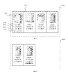
図6は、Webアプリケーションサーバ108の帳票出力処理部302−3が、図4のレコード411、412、413の3レコード分のコンテンツデータを、図5のテンプレートに基づいて合成処理して、バリアブルデータ出力した例を示す図である。表紙601には、図5の表紙テンプレート501が出力される。裏表紙605には、図5の裏表紙テンプレート503が出力される。データ出力ページ602、603、604には、図5のデータ出力テンプレート502に、図4のレコード行411、412、413がそれぞれ挿入され、出力される。
6 shows that the form output processing unit 302-3 of the
出力ページ604上の、イメージ611は、イメージフィールド511に挿入された、ファイルパス列403、レコード行413のデータに紐付けられたイメージである。データ612は、名前フィールド512に挿入された、名前列401、レコード行413のデータである。データ613は、価格フィールド513に挿入された、価格列402、レコード行413のデータである。データ614は、注釈1フィールド514に挿入された、注釈1列404、レコード行413のデータである。データ615は、注釈2フィールド515に挿入された、注釈2列405、レコード行413のデータである。出力ページ602、603についても604と同様に、ページ602にはレコード行411、ページ603にはレコード行412のデータが挿入される。
なお、図5のテンプレートデータの各データフィールドには、配置すべきコンテンツデータに対する配置属性が定義されているものとする。例えば、イメージフィールドには、イメージデータの縦横比を維持したまま、フィールド領域内に収まるようにイメージデータを自動的に拡縮することが定義されている。また、各テキストフィールドには、コンテンツデータである配置すべきテキストデータのフォントサイズ、文字ピッチ、フォントタイプ、文字色が定義されている。そして、コンテンツデータをフィールド領域に配置する場合に、各フィールド領域に定義されている配置属性に従って、コンテンツデータを変換処理して配置することにより、出力ページ604が生成される。ここで、各フィール領域にコンテンツデータを配置するときの配置属性を定義すること自体は既知の技術であるため、より具体的な説明は省略する。
An
It is assumed that an arrangement attribute for content data to be arranged is defined in each data field of the template data in FIG. For example, in the image field, it is defined that the image data is automatically scaled so as to fit within the field area while maintaining the aspect ratio of the image data. Each text field defines a font size, a character pitch, a font type, and a character color of text data to be arranged as content data. When the content data is arranged in the field area, the
次に、帳票出力処理302−3等が行う処理に係る、注釈のマージのパターン(マージパターン1)について、図7、図8、図9、図10を用いて説明する。マージパターンとは、注釈データのように、与えられたフィールド領域にすべてのレコードで繰り返し配置すべきでない場合に、どのように注釈データを出力するかを定義したものであり、このマージパターンを注釈出力方法(注釈出力タイプ)とも呼ぶ。また、マージパターンに従って、注釈データを変換して出力することを、本実施例では、マージまたは置換と呼ぶことにする。
図7は、図6で示す通常の帳票出力に対して、注釈をマージして出力した場合の例を示す図である。表紙701、裏表紙706は、それぞれ図6の表紙601、裏表紙605、と同じである。データ出力ページ702、703、704は、マージ対象である注釈1及び注釈2のフィールドを除いて、図6のデータ出力ページ602、603、604と同じである。ページ705は、注釈等の付記情報をまとめて出力するためのページである。ページ705は、図7では裏表紙の手前に挿入されているが、挿入位置は、前述したように帳票作成部302−5によりテンプレートデータに定義されている。
Next, an annotation merging pattern (merge pattern 1) related to the processing performed by the form output processing 302-3 and the like will be described with reference to FIGS. 7, 8, 9, and 10. FIG. A merge pattern defines how annotation data is output when it should not be repeatedly placed in a given field area for all records, such as annotation data. Also called an output method (annotation output type). In the present embodiment, converting annotation data according to a merge pattern and outputting it is called merge or replacement.
FIG. 7 is a diagram showing an example in which annotations are merged and output with respect to the normal form output shown in FIG. The
情報711は、注釈1、注釈2の情報を注釈記号に置き換えて表示したものである。また、注釈1及び注釈2は、マージ対象で、注釈1は、注釈2に関連付けられており、注釈1の注釈記号と、注釈2の注釈記号とが、注釈2フィールドに並べて出力される。
情報712は、注釈1の情報で、注釈1の注釈記号と、注釈1の内容と、が記載されている。情報713は、注釈2の情報で、注釈2の注釈記号と、注釈2の内容と、が記載されている。
The
図8及び図9は、帳票作成部302−5により提供される設定ダイアログであり、注釈記号の書式設定をユーザに入力させるための設定画面の一例を示す図である。コンテンツデータの注釈データを置き換えるための注釈記号には、文字をベースとしたものと、アイコンをベースとしたものと、2種類がある。図8は、文字をベースとした注釈記号の設定方法を示す図である。一方、図9は、アイコンをベースとした注釈記号の設定方法を示す図である。 8 and 9 are setting dialogs provided by the form creation unit 302-5, and are diagrams illustrating an example of a setting screen for allowing a user to input annotation symbol format settings. There are two types of annotation symbols for replacing annotation data of content data, one based on characters and one based on icons. FIG. 8 is a diagram showing a setting method of annotation symbols based on characters. On the other hand, FIG. 9 is a diagram showing a method for setting annotation symbols based on icons.
図8のリストボックス801は、注釈記号のフォーマットを選択するリストボックスである。リストボックス802は、番号の書式を表すリストボックスである。エディットボックス803は、番号の桁数を表すエディットボックスである。エディットボックス804は、開始番号を表すエディットボックスである。出力例805は、操作者がリストボックス801、リストボックス802、エディットボックス803、エディットボックス804の設定を行った結果、作成される注釈記号のイメージである。つまり、出力例805は、注釈データをどのように置き換えられるかを示している。文字ベースの注釈記号は、マージ対象となる注釈情報に対して、順に番号が割り当てられる。 A list box 801 in FIG. 8 is a list box for selecting a format of an annotation symbol. A list box 802 is a list box representing a number format. An edit box 803 is an edit box indicating the number of digits of the number. An edit box 804 is an edit box representing a start number. An output example 805 is an image of an annotation symbol created as a result of the operator setting the list box 801, list box 802, edit box 803, and edit box 804. That is, the output example 805 shows how the annotation data can be replaced. The character-based annotation symbols are assigned numbers sequentially to the annotation information to be merged.
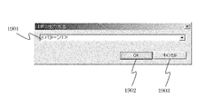
文字ベースの注釈記号では、全ての注釈に対してフォーマットを指定するのに対し、アイコンベースの注釈記号では、各注釈に対してアイコンを指定する。図9のリストボックス901は、注釈記号を割り当てる注釈情報を選択するリストボックスである。ここで選択項目として表示される内容は、図4のデータベーステーブルの注釈1、注釈2に対応している。また、注釈1列に複数種類のコメントが存在する場合、Webアプリケーションサーバ108は、種類分けをした上で、種類の区別をハイフンと、数字と、で表現する。
Character-based annotation symbols specify the format for all annotations, while icon-based annotation symbols specify an icon for each annotation. A
エディットボックス902は、リストボックス901で選択された注釈項目の内容を表示するエディットボックスである。イメージ903は、選択されたアイコンのイメージである。904は、アイコンの選択ボタンである。操作者は、選択ボタン904を押し、アイコンのイメージファイルを選択する。選択を行うと、選択したアイコンのイメージ903が表示される。905は、OKボタンである。操作者が、OKボタン905を押すと、注釈と、注釈記号アイコンと、の関連付けが確定される。906は、キャンセルボタンである。操作者が、キャンセルボタン906を押すと、注釈と、注釈記号アイコンと、の関連付けは設定されない。
このように、注釈データが置き換えられる置換情報は、出力例805のようにレコード毎に異なる関数で定義されることもでき、また、出力例903のように、注釈項目901毎に固定の情報(画像や図形)で定義されることもできる。
An
In this way, the replacement information in which the annotation data is replaced can be defined by a different function for each record as in the output example 805, and fixed information (for each
図10は、注釈のマージパターン1に係る処理を含む帳票出力処理を行う際の編集モジュール302の各処理部における制御手順を示すフローチャートである。ユーザがクライアントPC101(102、103)から、データ検索機能を用いて出力したいデータを選択し、テンプレートを指定して、Webアプリケーションサーバ108に出力要求を行う。Webアプリケーションサーバ108では、リクエスト処理モジュール301が出力要求を受信する。そして、リクエスト処理モジュール301が、データ管理モジュール302−1からデータを取得し、帳票管理モジュール302−4からテンプレートを取得して、帳票出力処理モジュール302−3に出力要求を出す。
FIG. 10 is a flowchart illustrating a control procedure in each processing unit of the
帳票出力処理モジュール302−3は、まず、表紙テンプレート501を用いて表紙を作成する(ステップS1001)。次に帳票出力処理モジュール302−3は、データ出力テンプレート502を用いて、データをテンプレートに挿入してページを作成して行く(ステップS1002)。ループ処理の中で、データが複数存在する場合、帳票出力処理モジュール302−3は、データ出力テンプレート502をデータ数だけコピーする。各データにおいて、帳票出力処理モジュール302−3は、項目の数だけ挿入処理を行う(ステップS1003)。
The form output processing module 302-3 first creates a cover using the cover template 501 (step S1001). Next, the form output processing module 302-3 creates a page by inserting data into the template using the data output template 502 (step S1002). In the loop processing, when there are a plurality of data, the form output processing module 302-3 copies the
例えば、図4の例では、名前、価格、イメージ、注釈1、注釈2、が項目である。データ挿入時には、帳票出力処理モジュール302−3は、まず、マージ対象属性を参照し、マージ項目か否かを判定する(ステップS1004)。ここで、マージ項目でなければ(ステップS1004においてNo)、帳票出力処理モジュール302−3は、そのままテンプレートへの出力処理を行う(ステップS1005)。マージ項目の場合(ステップS1004においてYes)、帳票出力処理モジュール302−3は、データが存在するか否かを判定する(ステップS1006)。
For example, in the example of FIG. 4, the name, price, image,
データが存在しない場合(ステップS1006においてYes)、出力する必要がないため、帳票出力処理モジュール302−3は、処理を行わない。データが存在する場合(ステップS1006においてNo)、帳票出力処理モジュール302−3は、そのマージ項目のデータに割り当てられた注釈記号をテンプレートに出力する(ステップS1007)。 If there is no data (Yes in step S1006), the form output processing module 302-3 does not perform processing because there is no need to output the data. If data exists (No in step S1006), the form output processing module 302-3 outputs the annotation symbol assigned to the data of the merge item to the template (step S1007).
帳票出力処理モジュール302−3は、出力すべきであったデータを、後で出力するためにスタックに追加しておく(ステップS1008)。このスタックは、マージ項目のデータに関して種類分けされており、同じデータであればマージされる。データを出力後、帳票出力処理モジュール302−3は、次の出力データが存在するか否かを判定する(ステップS1009)。 The form output processing module 302-3 adds the data that should have been output to the stack for later output (step S1008). This stack is classified with respect to merge item data. If the data is the same, they are merged. After outputting the data, the form output processing module 302-3 determines whether or not next output data exists (step S1009).
次の出力データが存在する場合(ステップS1009においてNo)、帳票出力処理モジュール302−3は、次のページにデータ出力テンプレート502のコピーを挿入する(ステップS1010)。全データが出力されたら(ステップS1009においてYes)、帳票出力処理モジュール302−3は、省略したマージ項目のデータを出力するためのページを挿入する(ステップS1011)。そして、帳票出力処理モジュール302−3は、スタックに格納してあった注釈等のマージ項目データを出力する(ステップS1012)。続いて、帳票出力処理モジュール302−3は、裏表紙テンプレート503を用いて裏表紙を作成する(ステップS1015)。そして、帳票出力処理モジュール302−3は、図10に示す処理を終了する。
If the next output data exists (No in step S1009), the form output processing module 302-3 inserts a copy of the
次に、帳票出力処理302−3等が行う処理に係る、注釈のマージのパターン(マージパターン2)について、図11、図12、図13、図14、図15、図16を用いて説明する。 Next, an annotation merging pattern (merge pattern 2) related to the processing performed by the form output processing 302-3 and the like will be described with reference to FIGS. 11, 12, 13, 14, 15, and 16. FIG. .
図11は、バリアブルデータ出力するコンテンツデータを格納しているデータベースのテーブルを示す図(その2)である。図11に示されるように、テーブルは、データ項目列として、名前列1101、価格列1102、イメージファイルへのファイルパス(イメージ)列1103、1つ目の注釈(注釈1)列1104、2つ目の注釈(注釈2)列1105、を含む。注釈1列1104、注釈2列1105には、注釈をマージする属性が設定されている。なお、図11では、説明の便宜上、出力する情報のみを1テーブルとして記載しているが、出力する情報が別のデータベースやテーブルに存在していたり、出力しない情報がテーブルに含まれていたりしてもよい。
FIG. 11 is a diagram (part 2) illustrating a database table storing content data to be output as variable data. As shown in FIG. 11, the table includes a
図12は、図11で示す各レコード行のコンテンツデータを配置するためのテンプレートデータを示す図である。データ出力テンプレート1201は、コンテンツデータが配置される1ページ分の出力テンプレートである。なお、図12の例では用意していないが、図5で示したように、データ出力テンプレート1201に表紙、裏表紙を登録することも可能である。イメージフィールド1211は、ファイルパス列1103の各データに紐付けられたイメージを出力するための領域である。名前フィールド1212は、名前列1101の各データを出力するための領域である。価格フィールド1213は、価格列1102の各データを出力するための領域である。注釈1フィールド1214は、1つ目の注釈列1104の各データを出力するための領域である。注釈2フィールド1215は、2つ目の注釈列1105の各データを出力するための領域である。
FIG. 12 is a diagram showing template data for arranging the content data of each record row shown in FIG. The
データ出力テンプレート1201は、4つのデータを出力するための領域を持っている。出力するデータ数に応じて、各フィールド1211、1212、1213、1214、1215の領域が、1216、1217、1218の領域にコピーされる。データ出力テンプレート1201の例では、右方向に3つのコピーを作成する設定となっているが、下方向へコピーを作成する設定や、上下段組のように右方向と、下方向とにコピーを作成する設定もある。ページ内のデータが埋まると、帳票出力処理モジュール302−3は、次のページにデータ出力テンプレート1201のコピーを挿入する。
The
図13は、図11の情報を図12のテンプレートに基づいて、帳票出力処理モジュール302−3が、注釈のマージを行わずに出力した例を示す図である。1301は、ページ1、1302は、ページ2を指す。データ出力テンプレート1201は、1ページに4つのデータを出力する設定となっており、出力するデータが6つであるため、ページ1(1301)に4つ、ページ2(1302)に2つのデータが出力されている。
FIG. 13 is a diagram illustrating an example in which the form output processing module 302-3 outputs the information in FIG. 11 without merging annotations based on the template in FIG. 1301 indicates
1311は、データの境界線である。操作者は、線を引くか引かないかの選択が可能である。1312は、イメージ、1313は、名前、1314は、価格、1315は、注釈1、1316は、注釈2である。なお、1316の注釈2は、データが無いため何も表示されていない。
図14は、図11のデータを図12のテンプレートを改良した図15のテンプレートに基づいて、帳票出力処理モジュール302−3が、注釈のマージを行って出力した例を示す図である。1401は、ページ1、1402は、ページ2を指す。データの配置位置と、ページ作成手法と、は図13と同様である。
FIG. 14 is a diagram illustrating an example in which the form output processing module 302-3 outputs the data of FIG. 11 by merging annotations based on the template of FIG. 15 obtained by improving the template of FIG. 1401 indicates
1411は、データの境界線であり、操作者は、線を引くか引かないかの選択が可能である。1412は、イメージ、1413は、名前、1414は、価格、1415は、注釈1の領域、1416は、注釈2の領域である。注釈1及び注釈2は、マージ対象項目で、注釈2は、注釈1に関連付けされている。そのため、注釈1及び注釈2は、注釈記号に置き換えられると共に、注釈2の注釈記号は、注釈1フィールドに併記される。
1417は、注釈の内容である。図15のテンプレートに定義されているように、ここでは、注釈はページ単位にマージされ、出力されている。ページ1(1401)には注釈記号※1と、注釈記号※2と、の注釈が存在しているため、注釈※1と、注釈※2と、の内容が出力されている。一方、ページ1402には注釈記号※2と、注釈記号※3と、の注釈が存在しているため、注釈※2と、注釈※3と、の内容が出力されている。
注釈内容を表示する位置の設定方法には、絶対位置と、相対位置と、の2通りがある。その設定方法を図15で説明する。図15は、設定方法を説明するための図である。 There are two methods for setting the position for displaying the annotation content: an absolute position and a relative position. The setting method will be described with reference to FIG. FIG. 15 is a diagram for explaining the setting method.
図15の1501は、各コンテンツデータが配置されて出力されるテンプレートページを示す。境界線1511は、図12に示したように、1レコード分のコンテンツデータが配置されるフィールド領域1211−1215が定義されている流し込み領域を示している。そして、点線1512は、流し込み領域1511を複数有する流し込み領域群を示している。点線1512は、説明の便宜上表示しているもので、実際に表示されるものではない。フィールド1513は、流し込み領域内で置換処理された注釈の内容を表示する注釈出力フィールドである。フィールド1513の線は説明の便宜上表示しているもので、図14に示したように、実際に表示されるものではない。このように、テンプレートページ1501には、置換処理された注釈の内容を表示する注釈出力フィールド1513が定義されている。このテンプレートページ1501に従って可変データ出力を行うことにより、図14の出力が得られる。次に、絶対位置設定と相対位置設定について説明する。
絶対位置設定とは、ページ上における注釈内容の位置を指定する方法である。例えば、次のような指定がされる。
(X座標、Y座標)
The absolute position setting is a method for designating the position of the annotation content on the page. For example, the following specification is made.
(X coordinate, Y coordinate)
相対位置設定とは、データ群からの位置を指定する方法である。データ群とは、点線1512の範囲を指し、点線1512に対してどこに配置するのか(左上、中央上、右上、左下、中央下、右下、等)、また、その配置場所とのマージンは幾つであるのかを指定する。例えば、次のような指定がされる。
(右下、上マージンが10pt、右マージンが10pt)
The relative position setting is a method for designating a position from the data group. The data group refers to the range of the dotted
(Bottom right, top margin is 10pt, right margin is 10pt)
図16は、注釈のマージパターン2に係る処理の流れを示すフローチャートである。ユーザがクライアントPC101(102、103)から、データ検索機能を用いて出力したいデータを選択し、テンプレートを指定して、Webアプリケーションサーバ108に出力要求を行う。Webアプリケーションサーバ108では、リクエスト処理モジュール301が出力要求を受信する。そして、リクエスト処理モジュール301が、データ管理モジュール302−1からデータを取得し、帳票管理モジュール302−4からテンプレートを取得して、帳票出力処理モジュール302−3に出力要求を出す。
FIG. 16 is a flowchart showing a flow of processing according to the
帳票出力処理モジュール302−3は、まず、データ出力テンプレート1201を用いて、データをテンプレートに挿入してページを作成して行く(ステップS1601)。ループ処理の中で、データが複数存在する場合、帳票出力処理モジュール302−3は、データ出力テンプレート1201をデータ数だけコピーする。各データにおいて、帳票出力処理モジュール302−3は、項目の数だけ挿入処理を行う(ステップS1602)。
The form output processing module 302-3 first creates a page by inserting data into the template using the data output template 1201 (step S1601). In the loop processing, when there are a plurality of data, the form output processing module 302-3 copies the
例えば、図11の例では、名前、価格、イメージ、注釈1、注釈2、が項目である。データ挿入時には、帳票出力処理モジュール302−3は、まず、マージ対象属性を参照し、マージ項目か否かを判定する(ステップS1603)。ここで、マージ項目でなければ(ステップS1603においてNo)、帳票出力処理モジュール302−3は、そのままテンプレートへの出力処理を行う(ステップS1604)。マージ項目の場合(ステップS1603においてYes)、帳票出力処理モジュール302−3は、データが存在するか否かを判定する(S1605)。
For example, in the example of FIG. 11, the name, price, image,
データが存在しない場合(S1605においてYes)、出力する必要がないため、帳票出力処理モジュール302−3は、処理を行わない。データが存在する場合(S1605においてNo)、帳票出力処理モジュール302−3は、そのマージ項目のデータに割り当てられた注釈記号をテンプレートに出力する(ステップS1606)。 If there is no data (Yes in S1605), the form output processing module 302-3 does not perform processing because there is no need to output the data. If data exists (No in S1605), the form output processing module 302-3 outputs the annotation symbol assigned to the data of the merge item to the template (step S1606).
帳票出力処理モジュール302−3は、出力すべきであったデータを、後で出力するためにスタックに追加しておく(ステップS1607)。このスタックは、マージ項目のデータに関して種類分けされており、同じデータであればマージされる。 The form output processing module 302-3 adds the data that should have been output to the stack for later output (step S1607). This stack is classified with respect to merge item data. If the data is the same, they are merged.
帳票出力処理モジュール302−3は、未だ挿入するデータが存在するか否か、又は、次のデータを同じページに挿入可能か否かを判定する(ステップS1608)。未だ挿入するデータが存在し、同じページに挿入可能である場合(ステップS1608においてNo)、次のデータへ進む。挿入するデータが存在しない、或いは、同ページには挿入できないという場合(ステップS1608においてYes)、帳票出力処理モジュール302−3は、注釈の挿入処理を行う。 The form output processing module 302-3 determines whether there is still data to be inserted or whether the next data can be inserted into the same page (step S1608). If data to be inserted still exists and can be inserted into the same page (No in step S1608), the process proceeds to the next data. If the data to be inserted does not exist or cannot be inserted on the same page (Yes in step S1608), the form output processing module 302-3 performs an annotation insertion process.
まず、帳票出力処理モジュール302−3は、注釈位置の取得を行う(ステップS1609)。そして、帳票出力処理モジュール302−3は、スタックに格納してあった注釈等のマージ項目データを出力し(ステップS1610)、スタックはクリアする(ステップS1611)。そして、帳票出力処理モジュール302−3は、次の出力データが存在するか否かを判定する(ステップS1612)。存在するようであれば(ステップS1612においてNo)、帳票出力処理モジュール302−3は、次のページにデータ出力テンプレート1201のコピーを挿入する(ステップS1613)。
First, the form output processing module 302-3 acquires an annotation position (step S1609). Then, the form output processing module 302-3 outputs merge item data such as annotations stored in the stack (step S1610), and clears the stack (step S1611). Then, the form output processing module 302-3 determines whether or not the next output data exists (step S1612). If it exists (No in step S1612), the form output processing module 302-3 inserts a copy of the
次に、帳票出力処理302−3等が行う処理に係る、注釈のマージのパターン(マージパターン3)について、図17、図18を用いて説明する。 Next, an annotation merging pattern (merge pattern 3) related to the processing performed by the form output processing 302-3 will be described with reference to FIGS.
図17は、帳票出力処理モジュール302−3が、注釈のマージパターン3でマージを行って出力した例を示す図である。1701は、データの境界線である。1702は、イメージ、1703は、名前、1704は、価格、1705は、注釈の領域である。マージパターン3では、帳票出力処理302−3は、注釈の内容によってデータをソートする。
FIG. 17 is a diagram illustrating an example in which the form output processing module 302-3 performs the merge using the
更に、帳票出力処理302−3は、データの境界線1701に関して、同じ注釈を持つデータ間の境界線を削除し、同じ注釈を持つ複数のデータがグループ化されたことを示す表示にする。そして、帳票出力処理302−3は、注釈の出力についてはグループ内の特定の注釈のみ出力させ、他は出力しないようにする。
Further, the form output process 302-3 deletes the boundary line between the data having the same annotation regarding the
図18は、注釈のマージパターン3に係る処理の流れを示すフローチャートである。ユーザがクライアントPC101(102、103)から、データ検索機能を用いて出力したいデータを選択し、テンプレートを指定して、Webアプリケーションサーバ108に出力要求を行う。Webアプリケーションサーバ108では、リクエスト処理モジュール301が出力要求を受信する。そして、リクエスト処理モジュール301が、データ管理モジュール302−1からデータを取得し、帳票管理モジュール302−4からテンプレートを取得して、帳票出力処理モジュール302−3に出力要求を出す。
FIG. 18 is a flowchart showing a flow of processing according to the
帳票出力処理モジュール302−3では、まず、データをテンプレートに挿入して行く(ステップS1801)。各データにおいては、帳票出力処理モジュール302−3は、項目の数、ループして(ステップS1802)、仮出力処理を行う(ステップS1803)。注釈のマージパターン3では、ページ単位にデータをソートするため、帳票出力処理モジュール302−3は、一旦仮出力をする。
In the form output processing module 302-3, first, data is inserted into a template (step S1801). In each data, the form output processing module 302-3 loops the number of items (step S1802) and performs a temporary output process (step S1803). In the
帳票出力処理モジュール302−3は、1ページ内のデータ出力可能数に達した、若しくは、出力するデータが最後か否かの判定を行う(ステップS1804)。1ページ内のデータ出力可能数に達しておらず、出力するデータの最後でもない場合(ステップS1804においてNo)、帳票出力処理モジュール302−3は、引き続きデータの仮出力処理を行う。1ページ内のデータ出力可能数に達した、或いは、出力するデータが最後である場合(ステップS1804においてYes)、帳票出力処理モジュール302−3は、仮出力したデータをマージ項目でソートする(ステップS1805)。 The form output processing module 302-3 determines whether the number of data that can be output in one page has been reached, or whether the data to be output is the last (step S1804). If the number of data outputs that can be output in one page has not been reached and the data to be output is not the last data (No in step S1804), the form output processing module 302-3 continues to temporarily output data. If the data output possible number in one page has been reached or the data to be output is the last (Yes in step S1804), the form output processing module 302-3 sorts the temporarily output data by the merge item (step S1804). S1805).
続いて、帳票出力処理モジュール302−3は、マージ項目が同じ内容のデータをグループ化する(ステップS1806)。帳票出力処理モジュール302−3は、グループ化したデータについて、境界線をグループ枠として修正し(ステップS1807)、特定のマージ項目以外を削除する(ステップS1808)。 Subsequently, the form output processing module 302-3 groups data having the same merge item (step S1806). The form output processing module 302-3 corrects the boundary line of the grouped data as a group frame (step S1807), and deletes items other than a specific merge item (step S1808).
帳票出力処理モジュール302−3は、仮出力で作成したデータを本出力する(ステップS1809)。そして、帳票出力処理モジュール302−3は、出力するデータが未だ存在するのかを判定する(ステップS1810)。存在する場合(ステップS1810においてNo)、帳票出力処理モジュール302−3は、次のページにテンプレートのコピーを挿入する(ステップS1811)。 The form output processing module 302-3 outputs the data created by the temporary output (step S1809). Then, the form output processing module 302-3 determines whether data to be output still exists (step S1810). If it exists (No in step S1810), the form output processing module 302-3 inserts a copy of the template in the next page (step S1811).
なお、本実施形態では、上述したように3種類のマージパターンを説明してきたが、操作者は、マージパターンを出力時に選択することができる。次に、マージパターンの選択に関して、図19を用いて説明する。 In the present embodiment, three types of merge patterns have been described as described above, but the operator can select a merge pattern at the time of output. Next, selection of a merge pattern will be described with reference to FIG.
図19は、Webアプリケーションサーバ108等が提供する、マージパターンを選択するダイアログボックスを示す図である。リストボックス1901は、マージパターンを選択するリストボックスである。1902は、OKボタンである。操作者が、OKボタン1902を押すと、マージパターンが決定される。1903は、キャンセルボタンである。操作者が、キャンセルボタン1903を押すと、マージパターンの選択は行われない。なお、マージパターンに出力上の制限が存在する場合、OKボタン1902が操作者によって押された際に、Webアプリケーションサーバ108において、出力対象のデータについて整合性のチェックが行われる。
FIG. 19 is a diagram showing a dialog box for selecting a merge pattern provided by the
[他の実施の形態]
上述した実施形態では、HTTPサーバ107と、Webアプリケーションサーバ108と、を別構成とした場合を例に挙げた。しかしながら、これに限定されるものではなく、HTTPサーバ107と、Webアプリケーションサーバ108と、を統合した単一の装置(筐体)としてもよい。
[Other embodiments]
In the above-described embodiment, the case where the
また、上述した実施形態では、Webアプリケーションを例として挙げたが、クライアント・サーバシステムとしてもよい。 In the above-described embodiment, the Web application is taken as an example, but a client / server system may be used.
また、上述した実施形態では、インターネット104、LAN105、106、等のネットワークを利用した例を挙げたが、ネットワークを介さず、クライアント上で出力処理を行うようにしてもよい。
In the above-described embodiment, an example in which a network such as the
以上、上述した実施形態では、自動出力の結果において、重要性の低い情報が不要に繰り返されることを防ぐことができる。よって、ユーザ等が手動で出力結果を修正する作業が不要になる。 As described above, in the above-described embodiment, it is possible to prevent unnecessary information from being repeated unnecessarily in the result of automatic output. This eliminates the need for the user to manually correct the output result.
以上、本発明の好ましい実施形態について詳述したが、本発明は係る特定の実施形態に限定されるものではなく、特許請求の範囲に記載された本発明の要旨の範囲内において、種々の変形・変更が可能である。 The preferred embodiments of the present invention have been described in detail above, but the present invention is not limited to such specific embodiments, and various modifications can be made within the scope of the gist of the present invention described in the claims.・ Change is possible.
1 システムバス
2 CPU
3 PMEM
4 外部記憶制御部
5 HD
6 FD
7 VRAM
8 表示出力制御部
9 CRT
10 入力制御部
1
3 PMEM
4
6 FD
7 VRAM
8 Display output controller 9 CRT
10 Input control unit
Claims (12)
コンテンツデータが配置されるフィールド領域が定義されているテンプレートデータを記憶するテンプレート記憶手段と、
前記テンプレートデータに配置される注釈情報を置き換えるための置換情報を設定する注釈置換設定手段と、
前記複数のレコード分のコンテンツデータを、前記テンプレートデータに定義されているフィールド領域に配置する際に、各レコードの注釈情報を前記注釈置換設定により設定されている置換情報に置き換える置換手段と、
を有することを特徴とする帳票出力制御装置。 A form output control device for arranging and outputting content data for a plurality of records in a database in template data,
Template storage means for storing template data in which field areas in which content data is arranged are defined;
Annotation replacement setting means for setting replacement information for replacing the annotation information arranged in the template data;
A replacement unit that replaces the annotation information of each record with the replacement information set by the annotation replacement setting when placing the content data for the plurality of records in the field region defined in the template data;
A form output control device characterized by comprising:
前記置換手段は、前記定義されている出力方法に従って、置き換えられた注釈情報の出力を行うことを特徴とする請求項1に記載の帳票出力制御装置。 The template data further defines a method for outputting the replaced annotation information,
2. The form output control apparatus according to claim 1, wherein the replacement unit outputs the replaced annotation information according to the defined output method.
テンプレート記憶手段に記憶されている、コンテンツデータが配置されるフィールド領域が定義されているテンプレートデータに、配置される注釈情報を置き換えるための置換情報を設定する注釈置換設定ステップと、
前記複数のレコード分のコンテンツデータを、前記テンプレートデータに定義されているフィールド領域に配置する際に、各レコードの注釈情報を前記注釈置換設定により設定されている置換情報に置き換える置換ステップと、
を有することを特徴とする帳票出力制御方法。 A form output control method executed by a form output control device that outputs content data for a plurality of records in a database by placing the data in template data,
An annotation replacement setting step for setting replacement information for replacing the annotation information to be arranged in the template data defined in the field area where the content data is arranged, stored in the template storage means;
A replacement step of replacing the annotation information of each record with the replacement information set by the annotation replacement setting when placing the content data for the plurality of records in the field area defined in the template data;
A form output control method characterized by comprising:
前記置換ステップでは、前記定義されている出力方法に従って、置き換えられた注釈情報の出力を行うことを特徴とする請求項5に記載の帳票出力制御方法。 The template data further defines a method for outputting the replaced annotation information,
6. The form output control method according to claim 5, wherein in the replacing step, the replaced annotation information is output according to the defined output method.
テンプレート記憶手段に記憶されている、コンテンツデータが配置されるフィールド領域が定義されているテンプレートデータに、配置される注釈情報を置き換えるための置換情報を設定する注釈置換設定ステップと、
前記複数のレコード分のコンテンツデータを、前記テンプレートデータに定義されているフィールド領域に配置する際に、各レコードの注釈情報を前記注釈置換設定により設定されている置換情報に置き換える置換ステップと、
を実行させることを特徴とするプログラム。 To a computer that outputs content data for multiple records in the database in template data,
An annotation replacement setting step for setting replacement information for replacing the annotation information to be arranged in the template data defined in the field area where the content data is arranged, stored in the template storage means;
A replacement step of replacing the annotation information of each record with the replacement information set by the annotation replacement setting when placing the content data for the plurality of records in the field area defined in the template data;
A program characterized by having executed.
前記置換ステップでは、前記定義されている出力方法に従って、置き換えられた注釈情報の出力を行うことを特徴とする請求項9に記載のプログラム。 The template data further defines a method for outputting the replaced annotation information,
10. The program according to claim 9, wherein the replacing step outputs the replaced annotation information in accordance with the defined output method.
Priority Applications (2)
| Application Number | Priority Date | Filing Date | Title |
|---|---|---|---|
| JP2006174380A JP4759458B2 (en) | 2006-06-23 | 2006-06-23 | Form output control device, form output control method, and program |
| US11/765,148 US7865818B2 (en) | 2006-06-23 | 2007-06-19 | Form output control apparatus, form output control method, and computer readable program |
Applications Claiming Priority (1)
| Application Number | Priority Date | Filing Date | Title |
|---|---|---|---|
| JP2006174380A JP4759458B2 (en) | 2006-06-23 | 2006-06-23 | Form output control device, form output control method, and program |
Publications (3)
| Publication Number | Publication Date |
|---|---|
| JP2008003944A JP2008003944A (en) | 2008-01-10 |
| JP2008003944A5 JP2008003944A5 (en) | 2009-07-30 |
| JP4759458B2 true JP4759458B2 (en) | 2011-08-31 |
Family
ID=38874854
Family Applications (1)
| Application Number | Title | Priority Date | Filing Date |
|---|---|---|---|
| JP2006174380A Expired - Fee Related JP4759458B2 (en) | 2006-06-23 | 2006-06-23 | Form output control device, form output control method, and program |
Country Status (2)
| Country | Link |
|---|---|
| US (1) | US7865818B2 (en) |
| JP (1) | JP4759458B2 (en) |
Families Citing this family (7)
| Publication number | Priority date | Publication date | Assignee | Title |
|---|---|---|---|---|
| US8732570B2 (en) * | 2005-09-08 | 2014-05-20 | Ricoh Co. Ltd. | Non-symbolic data system for the automated completion of forms |
| JP5022778B2 (en) * | 2007-05-28 | 2012-09-12 | 株式会社サトー知識財産研究所 | How to create a print sample form in a printer |
| JP5407520B2 (en) | 2009-04-24 | 2014-02-05 | 富士ゼロックス株式会社 | Print control apparatus and print control system |
| JP5388881B2 (en) * | 2010-01-28 | 2014-01-15 | 三菱電機株式会社 | Form input / output device |
| US20120131445A1 (en) | 2010-11-23 | 2012-05-24 | International Business Machines Corporation | Template-based content creation |
| US8972848B2 (en) | 2010-11-23 | 2015-03-03 | International Business Machines Corporation | Document renewal and translation |
| US20140258841A1 (en) * | 2013-03-07 | 2014-09-11 | Smugmug, Inc. | Method of building a customizable website |
Family Cites Families (8)
| Publication number | Priority date | Publication date | Assignee | Title |
|---|---|---|---|---|
| US6195665B1 (en) * | 1996-03-05 | 2001-02-27 | Tomorrow's Software, L.L.C. | Digital electrical computer apparatus, and methods for making and using the same, for template building, loading, and viewing |
| US7630986B1 (en) * | 1999-10-27 | 2009-12-08 | Pinpoint, Incorporated | Secure data interchange |
| WO2001052054A2 (en) * | 2000-01-14 | 2001-07-19 | Saba Software, Inc. | Method and apparatus for a business applications server |
| US7072934B2 (en) * | 2000-01-14 | 2006-07-04 | Saba Software, Inc. | Method and apparatus for a business applications server management system platform |
| US7047033B2 (en) * | 2000-02-01 | 2006-05-16 | Infogin Ltd | Methods and apparatus for analyzing, processing and formatting network information such as web-pages |
| US20040189713A1 (en) * | 2001-10-31 | 2004-09-30 | Metacyber.Net | Computer-based user interface for a memory-resident rapid comprehension document for original source information |
| US7143344B2 (en) * | 2002-06-12 | 2006-11-28 | Microsoft Corporation | Transformation stylesheet editor |
| JP2006024021A (en) | 2004-07-08 | 2006-01-26 | Nec Corp | System, method, server and apparatus for automatically generating business form |
-
2006
- 2006-06-23 JP JP2006174380A patent/JP4759458B2/en not_active Expired - Fee Related
-
2007
- 2007-06-19 US US11/765,148 patent/US7865818B2/en not_active Expired - Fee Related
Also Published As
| Publication number | Publication date |
|---|---|
| JP2008003944A (en) | 2008-01-10 |
| US20070300146A1 (en) | 2007-12-27 |
| US7865818B2 (en) | 2011-01-04 |
Similar Documents
| Publication | Publication Date | Title |
|---|---|---|
| US9436419B2 (en) | Selectively printing portions of a web page based on user selection | |
| US9880709B2 (en) | System and method for creating and displaying previews of content items for electronic works | |
| JP4759458B2 (en) | Form output control device, form output control method, and program | |
| US20100037168A1 (en) | Systems and methods for webpage design | |
| US20140136972A1 (en) | Panoptic Visualization Document Printing | |
| JP2008234148A (en) | Document display, document display method, and document display program | |
| JP2000200132A (en) | Icon display processor | |
| JP2009258966A (en) | Display controller and display control method | |
| US20130167016A1 (en) | Panoptic Visualization Document Layout | |
| JP4795030B2 (en) | Information processing apparatus, control method thereof, and program | |
| US20130167015A1 (en) | Panoptic Visualization Document Navigation | |
| JP4804241B2 (en) | Print data generation apparatus, print data generation method, and computer program | |
| EP2711897B1 (en) | Panoptic visualization document differencing | |
| US20130166997A1 (en) | Panoptic Visualization Document Collection | |
| JPWO2006051721A1 (en) | Document processing apparatus and document processing method | |
| JP4776998B2 (en) | Image layout editing apparatus, control method thereof, and program | |
| JP4133549B2 (en) | Structured document file management apparatus and structured document file management method | |
| JP2010122893A (en) | Variable printing system | |
| JP2007156898A (en) | Information processor, controlling method therefor, program, and storage medium | |
| WO2006051973A1 (en) | Document processing device and document processing method | |
| TWI802736B (en) | Presentation data production device, presentation data production method, and presentation data production program | |
| WO2014050960A1 (en) | Electronic publication creation device, electronic publication creation method, electronic publication perusal system, viewer device, and electronic publication perusal method | |
| JP2009015717A (en) | Form creation device, form creation method, program and storage medium | |
| JP2007179203A (en) | Slip retrieval device, slip retrieval method, program and computer-readable storage medium | |
| WO2006137561A1 (en) | Graph processor |
Legal Events
| Date | Code | Title | Description |
|---|---|---|---|
| A521 | Request for written amendment filed |
Free format text: JAPANESE INTERMEDIATE CODE: A523 Effective date: 20090616 |
|
| A621 | Written request for application examination |
Free format text: JAPANESE INTERMEDIATE CODE: A621 Effective date: 20090616 |
|
| A977 | Report on retrieval |
Free format text: JAPANESE INTERMEDIATE CODE: A971007 Effective date: 20110509 |
|
| TRDD | Decision of grant or rejection written | ||
| A01 | Written decision to grant a patent or to grant a registration (utility model) |
Free format text: JAPANESE INTERMEDIATE CODE: A01 Effective date: 20110531 |
|
| A01 | Written decision to grant a patent or to grant a registration (utility model) |
Free format text: JAPANESE INTERMEDIATE CODE: A01 |
|
| A61 | First payment of annual fees (during grant procedure) |
Free format text: JAPANESE INTERMEDIATE CODE: A61 Effective date: 20110606 |
|
| R150 | Certificate of patent or registration of utility model |
Free format text: JAPANESE INTERMEDIATE CODE: R150 |
|
| FPAY | Renewal fee payment (event date is renewal date of database) |
Free format text: PAYMENT UNTIL: 20140610 Year of fee payment: 3 |
|
| LAPS | Cancellation because of no payment of annual fees |