JP4750532B2 - Printing apparatus, removable medium, and printing control method - Google Patents
Printing apparatus, removable medium, and printing control method Download PDFInfo
- Publication number
- JP4750532B2 JP4750532B2 JP2005321377A JP2005321377A JP4750532B2 JP 4750532 B2 JP4750532 B2 JP 4750532B2 JP 2005321377 A JP2005321377 A JP 2005321377A JP 2005321377 A JP2005321377 A JP 2005321377A JP 4750532 B2 JP4750532 B2 JP 4750532B2
- Authority
- JP
- Japan
- Prior art keywords
- printing
- usb
- printer
- removable medium
- printing apparatus
- Prior art date
- Legal status (The legal status is an assumption and is not a legal conclusion. Google has not performed a legal analysis and makes no representation as to the accuracy of the status listed.)
- Expired - Fee Related
Links
Images


Classifications
-
- G—PHYSICS
- G06—COMPUTING; CALCULATING OR COUNTING
- G06F—ELECTRIC DIGITAL DATA PROCESSING
- G06F3/00—Input arrangements for transferring data to be processed into a form capable of being handled by the computer; Output arrangements for transferring data from processing unit to output unit, e.g. interface arrangements
- G06F3/12—Digital output to print unit, e.g. line printer, chain printer
- G06F3/1201—Dedicated interfaces to print systems
- G06F3/1202—Dedicated interfaces to print systems specifically adapted to achieve a particular effect
- G06F3/1203—Improving or facilitating administration, e.g. print management
- G06F3/1204—Improving or facilitating administration, e.g. print management resulting in reduced user or operator actions, e.g. presetting, automatic actions, using hardware token storing data
-
- G—PHYSICS
- G06—COMPUTING; CALCULATING OR COUNTING
- G06F—ELECTRIC DIGITAL DATA PROCESSING
- G06F3/00—Input arrangements for transferring data to be processed into a form capable of being handled by the computer; Output arrangements for transferring data from processing unit to output unit, e.g. interface arrangements
- G06F3/12—Digital output to print unit, e.g. line printer, chain printer
- G06F3/1201—Dedicated interfaces to print systems
- G06F3/1202—Dedicated interfaces to print systems specifically adapted to achieve a particular effect
- G06F3/1203—Improving or facilitating administration, e.g. print management
- G06F3/1209—Improving or facilitating administration, e.g. print management resulting in adapted or bridged legacy communication protocols, e.g. emulation, protocol extension
-
- G—PHYSICS
- G06—COMPUTING; CALCULATING OR COUNTING
- G06F—ELECTRIC DIGITAL DATA PROCESSING
- G06F3/00—Input arrangements for transferring data to be processed into a form capable of being handled by the computer; Output arrangements for transferring data from processing unit to output unit, e.g. interface arrangements
- G06F3/12—Digital output to print unit, e.g. line printer, chain printer
- G06F3/1201—Dedicated interfaces to print systems
- G06F3/1223—Dedicated interfaces to print systems specifically adapted to use a particular technique
- G06F3/1229—Printer resources management or printer maintenance, e.g. device status, power levels
- G06F3/1232—Transmitting printer device capabilities, e.g. upon request or periodically
-
- G—PHYSICS
- G06—COMPUTING; CALCULATING OR COUNTING
- G06F—ELECTRIC DIGITAL DATA PROCESSING
- G06F3/00—Input arrangements for transferring data to be processed into a form capable of being handled by the computer; Output arrangements for transferring data from processing unit to output unit, e.g. interface arrangements
- G06F3/12—Digital output to print unit, e.g. line printer, chain printer
- G06F3/1201—Dedicated interfaces to print systems
- G06F3/1223—Dedicated interfaces to print systems specifically adapted to use a particular technique
- G06F3/1237—Print job management
- G06F3/1244—Job translation or job parsing, e.g. page banding
- G06F3/1247—Job translation or job parsing, e.g. page banding by conversion to printer ready format
-
- G—PHYSICS
- G06—COMPUTING; CALCULATING OR COUNTING
- G06F—ELECTRIC DIGITAL DATA PROCESSING
- G06F3/00—Input arrangements for transferring data to be processed into a form capable of being handled by the computer; Output arrangements for transferring data from processing unit to output unit, e.g. interface arrangements
- G06F3/12—Digital output to print unit, e.g. line printer, chain printer
- G06F3/1201—Dedicated interfaces to print systems
- G06F3/1278—Dedicated interfaces to print systems specifically adapted to adopt a particular infrastructure
- G06F3/128—Direct printing, e.g. sending document file, using memory stick, printing from a camera
Landscapes
- Engineering & Computer Science (AREA)
- Theoretical Computer Science (AREA)
- Human Computer Interaction (AREA)
- Physics & Mathematics (AREA)
- General Engineering & Computer Science (AREA)
- General Physics & Mathematics (AREA)
- Accessory Devices And Overall Control Thereof (AREA)
- Record Information Processing For Printing (AREA)
Description
本発明は、印刷装置、リムーバブルメディア、及び印刷制御方法に関し、特に、リムーバブルメディアに記憶された印刷データを印刷するために用いて好適なものである。 The present invention relates to a printing apparatus , a removable medium , and a printing control method , and particularly suitable for printing print data stored in a removable medium.
従来から、ネットワークに接続されていない情報機器からの指示に基づいて印刷装置で印刷を行う場合に、USB(Universal Serial Bus)ケーブルを介して情報機器と印刷装置とを相互に接続することが行われている。また、情報機器に一時的にネットワークケーブルを接続し、情報機器がネットワーク経由で印刷装置と通信できるようにすることも行われている。さらに、情報機器を無線LANに接続し、情報機器がネットワーク経由で印刷装置と通信できるようにすることも行われている。
ここで、情報機器としては、デスクトップ型のパーソナルコンピュータ(以下PCと呼ぶ)と、ノート型のPCやPDA(Personal Digital Assistance)等のモバイル機器とが挙げられる。
Conventionally, when printing is performed by a printing apparatus based on an instruction from an information apparatus that is not connected to a network, the information apparatus and the printing apparatus are connected to each other via a USB (Universal Serial Bus) cable. It has been broken. In addition, a network cable is temporarily connected to the information device so that the information device can communicate with the printing apparatus via the network. Furthermore, an information device is connected to a wireless LAN so that the information device can communicate with a printing apparatus via a network.
Here, examples of the information device include a desktop personal computer (hereinafter referred to as a PC) and a mobile device such as a notebook PC or PDA (Personal Digital Assistance).
しかしながら、USBケーブルを介してデスクトップ型のPCと印刷装置とを接続する場合、印刷装置とデスクトップ型のPCとの設置位置が離れていると、デスクトップ型のPCと印刷装置とをUSBケーブルで相互に接続するのは困難である。また、ノート型のPCやPDA等のモバイル機器と印刷装置とをUSBケーブルを介して接続する場合には、USBケーブルを持ち歩かなければならない。このため、モバイル機器の携帯性に支障が生じる。また、印刷装置の周辺に、モバイル機器を置いて作業する場所が確保できない場合もある。 However, when a desktop PC and a printing device are connected via a USB cable, if the installation positions of the printing device and the desktop PC are separated from each other, the desktop PC and the printing device are mutually connected with the USB cable. It is difficult to connect to. Also, when connecting a mobile device such as a notebook PC or PDA and a printing apparatus via a USB cable, the USB cable must be carried around. For this reason, the portability of the mobile device is hindered. In some cases, it is not possible to secure a place to work by placing a mobile device around the printing apparatus.
また、情報機器に一時的にネットワークケーブルを接続する場合、環境ごとに異なるネットワークの設定が煩わしい。また、ネットワークケーブルを持ち歩かなければならず、モバイル機器の携帯性に支障が生じる。さらに、前述したのと同様に、印刷装置の周辺に、モバイル機器を置いて作業する場所が確保できない場合もある。
また、情報機器を無線LANに接続する場合も、情報機器に一時的にネットワークケーブルを接続する場合と同様に、環境ごとに異なるネットワークの設定が煩わしい。そもそも無線LANの使用できる環境が、現時点ではまだまだ限定されている。
In addition, when a network cable is temporarily connected to an information device, setting of a different network for each environment is troublesome. In addition, it is necessary to carry a network cable, which hinders the portability of mobile devices. Further, as described above, there may be a case where a place where the mobile device is placed to work around the printing apparatus cannot be secured.
Also, when an information device is connected to a wireless LAN, different network settings for each environment are bothersome, as in the case of temporarily connecting a network cable to the information device. In the first place, the environment where wireless LAN can be used is still limited at present.
そこで、情報機器で作成した画像データをリムーバブルメディアの一例であるUSBメモリに保存し、画像データが保存されたUSBメモリを印刷装置に接続するようにすることが行われている(特許文献1を参照)。 Thus, image data created by an information device is stored in a USB memory that is an example of a removable medium, and the USB memory storing the image data is connected to a printing apparatus (see Patent Document 1). reference).
しかしながら、USBメモリを印刷装置に接続して印刷する場合、印刷装置で印刷可能な形式の画像データ(印刷データを含む)を情報機器側で作成してUSBメモリに書き込まなければならない。具体的に説明すると、まず、任意のアプリケーションで作成した文書を印刷したい場合は、この文書をアプリケーションからプリンタドライバへ出力して画像データファイルを生成する。このとき、プリンタドライバの出力先を印刷装置のポートではなく、ファイルへ出力を選択して出力先を所定のフォルダへ変更する必要がある。これにより、プリンタドライバにより生成された画像データファイルが、ファイル出力先として選択された情報機器内の任意のフォルダに格納される。次に、USBメモリを情報機器に装着し、ユーザによるポインティングデバイスを用いた操作により、所定のフォルダに格納された画像データファイルをUSBメモリへ保存させる。このように、USBメモリを印刷装置に接続して印刷を行う場合、従来の技術では、文書を印刷可能な画像データとしてUSBメモリへ保存する際の操作手順が多かった。 However, when printing is performed by connecting a USB memory to a printing apparatus, image data in a format that can be printed by the printing apparatus (including print data) must be created on the information device side and written to the USB memory. More specifically, when a document created by an arbitrary application is to be printed, the document is output from the application to the printer driver to generate an image data file. At this time, it is necessary to change the output destination to a predetermined folder by selecting output to a file instead of a port of the printing apparatus as an output destination of the printer driver. As a result, the image data file generated by the printer driver is stored in an arbitrary folder in the information device selected as the file output destination. Next, the USB memory is attached to the information device, and the image data file stored in a predetermined folder is saved in the USB memory by the user's operation using the pointing device. As described above, when printing is performed with the USB memory connected to the printing apparatus, in the conventional technology, there are many operation procedures for storing a document in the USB memory as printable image data.
以上のように、従来の技術では、USBメモリのようなリムーバブルメディアに印刷データを保存し、保存した印刷データを印刷するためには、上述したように複数段階の作業が必要となり、印刷操作に慣れていないユーザにとっては操作性が悪かった。
本発明は、このような問題点に鑑みてなされたものであり、リムーバブルメディアに印刷データを保存して印刷することを容易に行えるようにする仕組みを提供することを目的とする。
As described above, in the conventional technique, in order to save print data on a removable medium such as a USB memory and print the saved print data, a plurality of steps are required as described above. The operability was bad for users who are not used to it.
The present invention has been made in view of such problems, and an object of the present invention is to provide a mechanism for easily storing print data on a removable medium for printing.
本発明の印刷装置は、ホストコンピュータから送信される印刷データを受信した際に、当該印刷データに基づくファイルを作成し、印刷が指示された印刷装置のプリンタ構成ファイルに、当該作成したファイルを特定する情報を記述するリムーバブルメディアが接続される印刷装置であって、前記リムーバブルメディアのAプラグが接続された場合、前記印刷装置のプリンタ構成ファイルが当該リムーバブルメディアに存在するか否かを判別する判別手段と、前記判別手段により前記印刷装置のプリンタ構成ファイルが前記リムーバブルメディアに存在すると判別された場合、当該リムーバブルメディアから印刷データを読み出し、印刷処理を実行する実行手段と、を有し、前記リムーバブルメディアのBプラグが前記印刷装置に接続された場合、当該リムーバブルメディアにより、当該印刷装置のプリンタ構成ファイルが前記リムーバブルメディアに存在するか否かが判別された結果、当該印刷装置のプリンタ構成ファイルが当該リムーバブルメディアに存在すると判別された場合、当該リムーバブルメディアから印刷データを受信することを特徴とする。
本発明のリムーバブルメディアは、ホストコンピュータから送信される印刷データを受信した際、当該印刷データに基づくファイルを作成し、印刷が指示された印刷装置のプリンタ構成ファイルに、当該作成したファイルを特定する情報を記述するリムーバブルメディアであって、前記リムーバブルメディアのBプラグが前記印刷装置に接続された場合、当該印刷装置のプリンタ構成ファイルが前記リムーバブルメディアに存在するか否かを判断する判断手段と、前記判断手段により前記印刷装置のプリンタ構成ファイルが前記リムーバブルメディアに存在すると判断された場合、当該印刷装置に印刷データを送信する送信する送信手段と、を有し、前記リムーバブルメディアのAプラグが前記印刷装置に接続された場合、当該印刷装置により、当該印刷装置のプリンタ構成ファイルが当該リムーバブルメディアに存在するか否かが判別された結果、当該印刷装置のプリンタ構成ファイルが当該リムーバブルメディアに存在すると判別された場合、当該印刷装置により、当該リムーバブルメディアの印刷データが読み出され、印刷処理が実行されるようにしたことを特徴とする。
When receiving the print data transmitted from the host computer , the printing apparatus of the present invention creates a file based on the print data, and specifies the created file in the printer configuration file of the printing apparatus instructed to print. A determination is made to determine whether or not a printer configuration file of the printing apparatus exists in the removable medium when the removable medium A plug is connected to the printing apparatus in which removable media describing information to be processed is connected And an execution unit that reads out print data from the removable medium and executes a printing process when the determination unit determines that the printer configuration file of the printing apparatus exists in the removable medium. Media B plug connected to the printing device If it is determined by the removable media that the printer configuration file of the printing device exists on the removable media, it is determined that the printer configuration file of the printing device exists on the removable media. It is characterized by receiving print data from a removable medium.
When the removable media of the present invention receives print data transmitted from a host computer, it creates a file based on the print data, and identifies the created file in the printer configuration file of the printing apparatus instructed to print. Determining means for determining whether or not a printer configuration file of the printing device exists in the removable medium when the removable media B plug is connected to the printing device, and is a removable medium describing information; A transmission unit that transmits print data to the printing device when the determination unit determines that the printer configuration file of the printing device exists in the removable medium, and the A plug of the removable medium is When connected to a printing device, If the printer configuration file of the printing apparatus is determined to exist on the removable medium as a result of determining whether or not the printer configuration file of the printing apparatus exists on the removable medium, The print data of the medium is read and the print process is executed.
本発明の印刷制御方法は、ホストコンピュータから送信される印刷データを受信した際に、当該印刷データに基づくファイルを作成し、印刷が指示された印刷装置のプリンタ構成ファイルに、当該作成したファイルを特定する情報を記述するリムーバブルメディアと、当該リムーバブルメディアが接続される印刷装置とを用いた印刷制御方法であって、前記リムーバブルメディアのAプラグが前記印刷装置に接続された場合、当該印刷装置のプリンタ構成ファイルが前記リムーバブルメディアに存在するか否かを判別する判別工程と、前記判別工程により前記印刷装置のプリンタ構成ファイルが前記リムーバブルメディアに存在すると判別された場合、当該リムーバブルメディアから印刷データを読み出し、印刷処理を実行する実行工程と、前記リムーバブルメディアのBプラグが前記印刷装置に接続された場合、当該印刷装置のプリンタ構成ファイルが当該リムーバブルメディアに存在するか否かを判断する判断工程と、前記判断工程により前記印刷装置のプリンタ構成ファイルが前記リムーバブルメディアに存在すると判断された場合、当該印刷装置に印刷データを送信する送信する送信工程と、を有することを特徴とする。 In the print control method of the present invention, when print data transmitted from a host computer is received, a file based on the print data is created, and the created file is added to the printer configuration file of the printing apparatus instructed to print. A printing control method using a removable medium describing information to be specified and a printing apparatus to which the removable medium is connected, and when the A plug of the removable medium is connected to the printing apparatus, A determination step of determining whether or not a printer configuration file exists on the removable medium; and if the determination step determines that the printer configuration file of the printing apparatus exists on the removable medium, print data from the removable medium An execution step of executing reading and printing processing; When the B plug of the removable medium is connected to the printing apparatus, a determination process for determining whether a printer configuration file of the printing apparatus exists in the removable medium, and a printer configuration of the printing apparatus by the determination process A transmission step of transmitting print data to the printing apparatus when it is determined that the file exists on the removable medium.
本発明によれば、リムーバブルメディアに印刷データを保存して印刷することを容易に行うことができる。 According to the present invention , it is possible to easily store and print print data on a removable medium.
(第1の実施形態)
次に、図面を参照しながら、本発明の第1の実施形態について説明する。
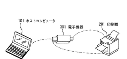
図1は、印刷システムの構成の一例を示した図である。
図1において、本発明の情報処理装置に好適なホストコンピュータ101は、USBデバイスを接続することが可能なUSBホストとしての機能を有する。印刷機201は、ホストコンピュータ101と、USBケーブルを介して通信可能であり、ホストコンピュータからの印刷データを受信するためのUSBデバイスとしての機能を有する。また、印刷装置(以下、印刷機)201は、マス・ストレージクラスのUSBデバイス(USBメモリのこと)が接続されると、接続されたUSBデバイスから印刷ファイルを直接読み出すことが可能なUSBホストとしての機能も有している。言うまでもなく、ホストコンピュータ101と、印刷機201とは、USBケーブルを介して相互に接続することで通信することが可能であり、ホストコンピュータ101で生成された印刷データを印刷機201で印刷することが可能である。
(First embodiment)
Next, a first embodiment of the present invention will be described with reference to the drawings.
FIG. 1 is a diagram illustrating an example of a configuration of a printing system.
In FIG. 1, a
電子機器301は、フラッシュメモリに、マス・ストレージクラスのUSBデバイス機能と、簡易USBホストとしての機能とを持たせたものであり、持ち運び可能なリムーバブルメディアの一例である。電子機器301は、USB規格のUSBホストに接続するためのAプラグと、USBデバイスに接続するためのBプラグとを備えている。電子機器301は、Aプラグを介してホストコンピュータ101又は印刷機201に接続することが可能であり、Bプラグを介して印刷機201に接続することが可能である。
The
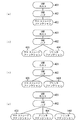
図2の(a)〜図2(c)は、各機器の構成の一例を示すブロック図である。
図2(a)は、ホストコンピュータ101の構成の一例を示すブロック図である。CPU102は、ホストコンピュータ101にインストールされたソフトウェアを動作させるものである。RAM103は、CPU102で動作するソフトウェアが、データの保存や自身の動作を行う際に使用される読み書き可能な記憶媒体である。ハードディスク(HDD)104は、アプリケーションソフトウェアやアプリケーションデータ等を保存する。また、印刷装置で印刷すべき印刷データを生成するプリンタドライバは、このハードディスク104に格納されており、動作時にRAM103に展開されてCPU102により実行される。ネットワークインターフェース105は、ホストコンピュータ101が、ネットワークを介して相互に接続された外部機器と通信を行うようにするためのインターフェースである。USBホストコントローラ106は、Aレセプタクル107に接続可能なUSBデバイス(例えば印刷機201及び電子機器301)との通信を統括制御する。
FIG. 2A to FIG. 2C are block diagrams illustrating an example of the configuration of each device.
FIG. 2A is a block diagram illustrating an example of the configuration of the
図2(b)は、印刷機201の構成の一例を示すブロック図である。操作パネル202は、ユーザによる印刷機201の設定を受け付ける。CPU203は、印刷機201にインストールされたソフトウェアを動作させるものである。RAM204は、CPU203で動作するソフトウェアが、データ保存や自身の動作を行う際に使用される読み書き可能な記憶媒体である。また、RAM204には、ユーザが操作パネル202を操作することにより設定されたプリンタ名(「印刷機201」の名称)が保存される。ROM205は、ソフトウェアやフォント情報等を保存する。また、ROM205には、印刷機201の特定情報である製品名「ABCDEF」、ベンダー名「GHIJK」が保存されている。
FIG. 2B is a block diagram illustrating an example of the configuration of the
ネットワークインターフェース206は、印刷機201が、ネットワークを介して相互に接続された外部機器と通信を行うようにするためのインターフェースであり、外部機器から印刷データを受信する。ハードレンダラ207は、CPU203を用いて動作するソフトウェアが印刷データから生成するディスプレイリスト(DL)を入力としてラスタイメージを生成する。プリンタエンジン208は、CPU203を用いて動作するソフトウェア及びハードレンダラ207が作り出すイメージデータの印刷を行う。
A
USBデバイスコントローラ209は、Bレセプタクル210及びUSBケーブルで接続されたUSBホストとの通信を統括制御する。USBデバイスコントローラ209は、USB規格のプリンタクラスのファンクションとして動作するように実装されており、3つのエンドポイントから構成されている。第1のエンドポイント(エンドポイント0)は、コントロール転送をサポートしている。第2のエンドポイント(エンドポイント1)は、バルクアウト転送をサポートしている。第3のエンドポイント(エンドポイント2)は、バルクイン転送をサポートしている。USBホストコントローラ211は、Aレセプタクル212に接続することが可能なUSBデバイス(例えば電子機器301)との通信を統括制御する。フィニッシャー214は、オプションコントローラ213による制御に従って、プリンタエンジン208で印刷された印刷物の後処理等を行うためのものである。
The
図2(c)は、リムーバブルメディアとしての電子機器301の構成の一例を示すブロック図である。
CPU302は、電子機器301にインストールされたソフトウェアを動作させるものである。USBホストコントローラ305、USBデバイスコントローラ307、USBデバイスコントローラ308が、各種イベントを受け付けて、電子機器301を統括的に制御する。ROM/RAM303は、CPU302を用いて動作するプログラムが格納されているROMと、CPU302のワークメモリ等として使用されるRAMとを備えた記憶領域である。
FIG. 2C is a block diagram illustrating an example of the configuration of the
The
Flashメモリ304は、データの読み書きと、電源がオフされた時のデータの保持との両方を行える大容量の半導体メモリである。後述するプリンタ構成情報ファイルとUSBコンフィグファイルは、このFlashメモリ304の所定のパスに格納される。USBホストコントローラ305は、Bプラグ306に接続されるUSBデバイスとの通信を統括制御する。なお、Bプラグ306に接続されるUSBデバイスは、プリンタクラスファンクションを持つ。USBデバイスコントローラ307は、USBハブ309及びAプラグ310を介して接続されたUSBホストとの通信を統括制御する。USBデバイスコントローラ307は、USB規格のマス・ストレージクラスのファンクションとして動作するように実装されており、4つのエンドポイントから構成されている。第1のエンドポイント(エンドポイント0)は、コントロール転送をサポートしている。第2のエンドポイント(エンドポイント1)は、バルクアウト転送をサポートしている。第3のエンドポイント(エンドポイント2)は、バルクイン転送をサポートしている。第4のエンドポイント(エンドポイント3)は、インターラプト転送をサポートしている。USBデバイスコントローラ307は、通信中のUSBホストに対してFlashメモリ304の領域をファイルシステムとして提供する。
The
USBデバイスコントローラ308は、USBハブ309及びAプラグ310を介して接続されたUSBホストとの通信を統括制御する。USBデバイスコントローラ308は、USB規格のプリンタクラスのファンクションとして動作するように実装されており、3つのエンドポイントから構成されている。第1のエンドポイント(エンドポイント0)は、コントロール転送をサポートしている。第2のエンドポイント(エンドポイント1)は、バルクアウト転送をサポートしている。第3のエンドポイント(エンドポイント2)は、バルクイン転送をサポートしている。
The
電源制御回路311は、電子機器301への電力供給を制御する。Bプラグ306に、USBデバイスが接続され、電子機器301がUSBホストとして動作する場合、電源制御回路311は蓄電池312から電力供給を受ける。これにより、電子機器301の動作に必要な電力供給が行われる。Aプラグ310に、USBホストが接続され、電子機器301がUSBデバイスとして動作する場合は、接続されたUSBホストに設けられた電源供給ライン(VBUS)を介して供給される電力により、電子機器301に必要な電力が供給される。そして、この電力によって、蓄電池312への充電が行われる。
The
次に、図3と、図4のフローチャートとを参照しながら、電子機器301がホストコンピュータ101に接続されたときの動作の一例を説明する。
図3は、電子機器301に設けられたAプラグ310が、ホストコンピュータ101のAレセプタクル107に接続されたときに構成されるUSB接続の状態の一例を示す図である。図4は、電子機器301が接続されたときのホストコンピュータ101の動作の一例を説明するフローチャートである。
Next, an example of the operation when the
FIG. 3 is a diagram illustrating an example of a USB connection state configured when the
図3において、USBホスト401は、図2(a)に示したUSBホストコントローラ106上に構成される。USBハブ402は、図2(c)に示したUSBハブ309上に構成される。マス・ストレージファンクション(USBファンクション)403は、図2(c)に示したUSBデバイスコントローラ307上に構成される。プリンタファンクション(USBファンクション)404は、USBデバイスコントローラ308上に構成される。
図3(a)は、Flashメモリ304上にプリンタクラスを表す「/_printer」がないときに構成されるUSB接続の状態の一例を示す図である。図3(b)は、Flashメモリ304上に「/_printer」があるときに構成されるUSB接続の状態の一例を示す図である。
In FIG. 3, the
FIG. 3A is a diagram illustrating an example of a USB connection state configured when “/ _printer” representing the printer class is not present on the
図4において、電子機器301のAプラグ310が、ホストコンピュータ101のAレセプタクル107に接続されると、USBホストコントローラ106が接続を検知する(ステップS101)。すると、USBホストコントローラ106は、USB規格に基づくバス・エニュメレーション処理を実行して、USBハブ309の接続を確立する(ステップS102)。この状態で、USBホスト401とUSBハブ402との接続が確立されている。エニュメレーション処理とは、ホストが接続されているデバイスを識別し、アドレスを指定し、収集したディスクリプタ情報を固定のものとする一連のデバイス識別動作である。
In FIG. 4, when the
続いて、USBホストコントローラ106は、USBハブ309のダウンストリームポートに接続されている機器の問い合わせをUSBハブ309に行う(ステップS103)。USBハブ309とUSBデバイスコントローラ307は、常に接続されている状態である。このため、USBハブ309は、USBホストコントローラ106へ、USBデバイスコントローラ307が接続されていることを通知する。
USBホストコントローラ106は、USBデバイスコントローラ307がUSBハブ309に接続されていること認識すると、バス・エニュメレーション処理を実行してUSBデバイスコントローラ307との接続を確立する(ステップS104)。この時点で、USBホストコントローラ106は、USBデバイスコントローラ307上のファンクションがマス・ストレージファンクションであることを認識する。こうして、USBホスト401とマス・ストレージファンクション403とがUSBハブ402を介して相互に接続された状態となる(図3(a)及び図3(b)を参照)。
Subsequently, the
When recognizing that the
電子機器301の状態により、USBデバイスコントローラ308と、USBハブ309との接続状態が異なる。電子機器301の初期状態では、USBデバイスコントローラ308はUSBハブ309と接続されていない状態となっている。電子機器301のBプラグ306が、印刷機201のBレセプタクルに接続されると、CPU302は、Flashメモリ304上にプリンタクラスを表す「/_printer」を作成し、後述するUSBコンフィグファイルを作成する。そして、「/_printer」が作成されると、CPU302は、USBハブ309とUSBデバイスコントローラ308とが相互に接続されている状態にする。電子機器301が、印刷機201と接続されたときの「/_printer」の作成処理を含む動作については、図8で後述する。尚、このUSBコンフィグファイルは、ホストコンピュータ101のUSBホストコントローラ106がAレセプタクル107に接続される電子機器301(USBメモリ)を、プリンタクラスとして認識するために必要とされる。
The connection state between the
こうして、USBデバイスコントローラ308がUSBハブ309と相互に接続された状態にあるときには、USBハブ309は、USBホストコントローラ106へ、USBデバイスコントローラ308が接続されていることを通知する。USBホストコントローラ106は、USBデバイスコントローラ308がUSBハブ309に接続されていることを認識すると(ステップS105のYes)、バス・エニュメレーション処理を実行する。そして、USBデバイスコントローラ308との接続を確立する(ステップS106)。バス・エニュメレーション処理において、USBデバイスコントローラ308は、USB規格のプリンタクラスにおける各ディスクリプタのデバイス依存の値として、USBコンフィグファイル「/_printer/conf」に記載の値を読み出し、USBデバイスコントローラ308に設定する。そして、USBデバイスコントローラ308は、設定した値をUSBホストコントローラ106へ通知する。
Thus, when the
ここで、各ディスクリプタのデバイス依存の値とは、例えば、デバイスディスクリプタのベンダID(idVendor)である。この他、プロダクトID(idProduct)や、コンフィグレーションディスクリプタのインターフェース数(nNumInterfaces)等も各ディスクリプタのデバイス依存の値である。
前記USBコンフィグファイルは、電子機器301のBプラグ306が、印刷機201のBレセプタクルに接続されたときに生成されるファイルである。このUSBコンフィグファイルには、印刷機201のUSBデバイスコントローラ209から取得した値が格納されており、電子機器301のFlashメモリ304に書き込まれる。このUSBコンフィグファイルによって、USBホストコントローラ106は、電子機器301のUSBデバイスコントローラ308と、印刷機201のUSBデバイスコントローラ209とを同一のものと認識することが可能となる。
Here, the device-dependent value of each descriptor is, for example, the vendor ID (idVendor) of the device descriptor. In addition, the product ID (idProduct), the number of configuration descriptor interfaces (nNumInterfaces), and the like are also device-dependent values of each descriptor.
The USB configuration file is a file generated when the
USBホストコントローラ106とUSBデバイスコントローラ308とのバス・エニュメレーション処理が終了すると、USBホストコントローラ106は、USBデバイスコントローラ308上のファンクションがプリンタファンクションであると認識する。こうして、USBホスト401とプリンタファンクション404とがUSBハブ402を介して相互に接続された状態となる(図3(b)を参照)。
When the bus enumeration processing between the
続いて、図5のフローチャートを参照しながら、ホストコンピュータ101上で印刷機201を指定して印刷を行う場合のホストコンピュータ101の動作の一例を説明する。
Next, an example of the operation of the
まず、ユーザは、印刷機201で印刷を行うために、ホストコンピュータ101上で、印刷機201用のプリンタドライバを起動する。そうすると、プリンタドライバは、ネットワークインターフェース105又はUSBホストコントローラ106を介して、印刷機201と通信可能か否かを判断する(ステップS201)。前述したように、電子機器301のBプラグ306が、印刷機201のBレセプタクルに接続されると、電子機器301にUSBコンフィグファイルが作成される。よって、この接続処理後に、「/_printer」にUSBコンフィグファイルでプリンタクラスの定義がなされている電子機器301がAレセプタクル107に接続されている場合、ホストコンピュータ101は、電子機器301を印刷機201と同一であると認識することが可能である。このため、ホストコンピュータ101は、印刷機201と通信可能であると判断する。なお、ステップS201の判定では、起動されたプリンタドライバの出力先のポートがUSBポート(Aレセプタクル107)である場合、USBメモリ(電子機器301)がプリンタドライバに対応するプリンタと同一であるか判定される。
First, a user activates a printer driver for the
ホストコンピュータ101は、プリンタドライバに対応する印刷機201または同一と認識された電子機器301と通信可能であると判断すると(ステップS201のYes)、ステップS202へ進む。ステップS202では、プリンタドライバは、USBホストコントローラ106を介して、印刷機201またはプリンタクラスの電子機器301から、印刷機201の機能構成情報(プリンタ構成情報ファイルに機能構成情報のパスが指定されている)を取得する。ここで、印刷機201の機能構成情報とは、印刷機201の能力や状態を表す情報である。例えば、両面印刷機能の有無、カラー印刷機能の有無、フィニッシャー情報、及び印刷機201にセットされている用紙サイズやメディアタイプに関する情報等を含んでいる。尚、電子機器301は、後述するように、ホストコンピュータ101と接続されるか、印刷機201と接続されることに応じて、プリンタ構成情報ファイルと機能構成情報とが作成される。よって、少なくとも電子機器301がUSBコンフィグファイルを保持しており、印刷機であると判定される場合には、この電子機器301には、プリンタ構成情報ファイルと機能構成情報が作成済みでFlashメモリ304に格納されていることになる。
If the
ホストコンピュータ101は、ステップS202で取得した機能構成情報を元に、プリンタドライバ設定画面を表示して、ユーザにより行われた印刷設定と印刷開始の操作を受け付ける(ステップS203)。ここで、機能構成情報は、印刷機201に両面印刷機能がない場合にはプリンタドライバ設定画面で、両面印刷機能を選択できないようにするといった禁則処理等を行う際に使用される。ユーザが印刷開始の操作をすると、プリンタドライバは、ステップS203で行われたプリンタドライバの設定(印刷設定)に基づいて、印刷データの生成を行いスプールする(ステップS204)。スプールされた印刷データは、印刷機201またはプリンタクラスの電子機器301に接続されたインターフェース(Aレセプタクル107)を介して、印刷機201またはプリンタクラスの電子機器301に送信される。
The
ホストコンピュータ101は、印刷機201と通信不能もしくは電子機器301を印刷機201と同一でない判断すると(ステップS201のNo)、接続されているリムーバブルメモリデバイスを検索する(ステップS206)。リムーバブルメモリデバイスとは、USBコントローラ106が、プリンタクラスではなくマス・ストレージデバイスとして認識しているUSBデバイス(電子機器301)や、図示されないPCMCIAインターフェースに接続されているPCカード上のメモリ等である。ステップS206以下の処理では、電子機器301は、プリンタクラスではなくマス・ストレージデバイスとしてのリムーバブルメモリデバイスとして扱われる。リムーバブルメモリデバイスを検索した結果、接続されているリムーバブルメモリデバイスの数により、以降の処理が異なる(ステップS207)。
If the
ホストコンピュータ101の利用可能なリムーバブルメモリデバイスが存在しない場合、ホストコンピュータ101は、リムーバブルメモリデバイスの接続又は印刷機201と通信可能とすることを促すメッセージを表示する(ステップS208)。そして、ステップS201へ戻る。このとき、プリンタクラスとしての電子機器301が接続された場合は、ステップS201で印刷機と同一であるため、通信可能であると判定される。マス・ストレージデバイスの場合は、ステップS209へ進む。
ホストコンピュータ101の利用可能なリムーバブルメモリデバイスが1個のみである場合、ホストコンピュータ101は、接続されているリムーバブルメモリデバイスを印刷に使用するリムーバブルメモリデバイスとして設定する(ステップS209)。そして、接続されているリムーバブルメモリデバイスを印刷出力先として決定された場合、ホストコンピュータ101は、USBホストコントローラ106を介して、印刷機201のプリンタ構成ファイルの有無を検索する(ステップS210)。このリムーバブルメモリデバイスがはじめて印刷用に用いられる場合は、プリンタ構成ファイルは存在しない。
If there is no removable memory device available for the
When the
ここで、電子機器301が印刷データの格納用のメモリデバイスとして利用される場合、プリンタ構成情報ファイルは、リムーバブルメモリデバイス内の「/prc」ディレクトリ内にある「.prc」のプレフィクスのファイルとして存在する。ここで、電子機器301が、ホストコンピュータ101に印刷機として認識させる場合には、前述したように「/_printer」ディレクトリにプリンタ構成情報ファイルが生成される。このように、電子機器301の振る舞いにより、プリンタ構成情報ファイルが生成される格納場所(パス)が異ならせることを特徴としている。
このプリンタ構成情報ファイル内には、印刷機201を特定するための情報として、製品名を表す「ProductName」、及びベンダー名を表す「VenderName」といった情報が含まれる。この他、プリンタ構成情報ファイル内には、デバイス固有のプリンタ名称を表す「PrinterName」、及びネットワークに接続する際に印刷機201が使用するIPアドレスを表す「IPAddress」といった情報も含まれる。さらに、プリンタ構成情報ファイル内には、印刷機201の機能構成情報を格納したファイルアドレス(パス)を表す「ConfigrationFile」、及び印刷データを格納したファイルのアドレス群を表す「Datafile」といった情報も含まれている。
When the
This printer configuration information file includes information such as “ProductName” representing a product name and “VenderName” representing a vendor name as information for specifying the
「Datafile」内には、印刷データのアドレスを表す「Data」が0個以上含まれる。また、プリンタ構成情報ファイルには、各ディスクリプタのデバイス依存情報が格納されているファイルのアドレス「USBconfFile」の情報が含まれる。ここで、各ディスクリプタのデバイス依存情報は、USBデバイスコントローラの設定情報である。 “Datafile” includes zero or more “Data” representing the address of the print data. Further, the printer configuration information file includes information on the address “USBconfFile” of the file in which the device-dependent information of each descriptor is stored. Here, the device-dependent information of each descriptor is setting information of the USB device controller.
ホストコンピュータ101は、これらの情報を参照して、印刷機201のプリンタ構成情報ファイルの有無を検索する。図6はプリンタ構成情報ファイルの一例である。図6に示す内容のプリンタ構成情報ファイル601が、「/prc/p201.prc」としてリムーバブルメモリデバイス内に存在するとする。その場合、製品名、ベンダー名、プリンタ名が印刷機201のものと一致するため、印刷機201のプリンタ構成情報ファイルがあると判断する(ステップS211のYes)。「/prc」ディレクトリ内に「.prc」のプレフィクスを持つファイルがない場合、又はあってもファイル内の印刷機を特定するための情報が印刷機201のものと一致しない場合、プリンタ構成情報ファイルがないと判断する(ステップS211のNo)。
The
印刷機201のプリンタ構成情報ファイルがあった場合、ホストコンピュータ101は、機能構成情報を特定するため、プリンタ構成情報ファイル内に記載されている「ConfigrationFile」を参照する。そして、印刷機201の機能構成情報が格納されているファイルを読み出し、機能構成情報の取得を行う(ステップS212)。一方、印刷機201のプリンタ構成情報ファイルがなかった場合、ホストコンピュータ101は、ステップS209で設定された印刷に使用するリムーバブルメモリデバイスに対するプリンタ構成情報ファイルと、機能構成情報ファイルとを新規に作成する(ステップS213)。具体的に、プリンタ構成情報ファイルとして「/prc/p201.prc」を、機能構成情報ファイルとして「/prc/ABCDEF.conf」をそれぞれ新規に作成する。
When there is a printer configuration information file of the
新規に作成するプリンタ構成情報ファイルの内容のうち、「ProductName」には「ABCDEF」、「VenderName」には「GHIJK」、「PrinterName」には「印刷機201の名称」がそれぞれ設定される。また、印刷機201のポートがネットワークであればそのポートの示すIPアドレスが「IPAddress」に設定される。これに対して、印刷機201のポートがUSBポートであれば「IPAddress」には何も設定しない。さらに、「ConfigrationFile」には、「/prc/ABCDEF.conf」を設定し、「Datafile」には何も設定しない。
「USBconfFile」は、電子機器301が印刷装置201に接続したときに、電子機器301が作成する情報であり、また、「/prc」ディレクトリに作成されるプリンタ構成情報ファイルは、印刷用のストレージデバイスとして利用するため、何も設定しない。新規に作成された機能構成情報ファイル「/prc/ABCDEF.conf」には、ホストコンピュータ101のプリンタドライバが現在保持している印刷機201の機能構成情報(両面ユニット、カラー印刷機能など)を格納する。
以上のようにしてステップS213でプリンタ構成ファイルと、機能構成情報ファイルとが作成されると、ホストコンピュータ101は、プリンタ構成ファイル内に記載されている「ConfigrationFile」を参照する。そして、ホストコンピュータ101は、印刷機201の機能構成情報が格納されているファイルを読み出し、機能構成情報の取得を行う(ステップS212)。
Among the contents of the newly created printer configuration information file, “ABCDEF” is set in “ProductName”, “GHIJK” is set in “VenderName”, and “Name of
“USBconfFile” is information created by the
When the printer configuration file and the function configuration information file are created in step S213 as described above, the
そして、ホストコンピュータ101は、取得した機能構成情報を元に、プリンタドライバ設定画面を表示して、ユーザにより行われた印刷設定と印刷開始の操作を受け付ける(ステップS214)。ユーザが印刷開始の操作をすると、プリンタドライバは、ステップS214で行われたプリンタドライバの設定(印刷設定)に基づいて、印刷データの生成を行いスプールする(ステップS215)。スプールされた印刷データは、印刷に使用するリムーバブルメモリデバイス内に、「.prn」のプレフィクスを持つファイルとして新規に作成される。作成されたファイルのリムーバブルメモリ内のアドレスを、印刷機201のプリンタ構成ファイル内の「Datafile」中に「Data」を追加して記述する。
Then, the
ホストコンピュータ101の利用可能なリムーバブルメモリデバイスが2個以上あると判定された場合(ステップS207の「2個以上」)、印刷機201のプリンタ構成情報ファイルの有無を、各リムーバブルメモリデバイスにおいて検索する(ステップS217)。ステップS217でのプリンタ構成情報ファイルの検索結果により、以降の処理が異なる(ステップS218)。印刷機201のプリンタ構成情報ファイルが、いずれのリムーバブルメモリデバイス内に見つからなかった場合(ステップS218の「0」)、どのリムーバブルメモリデバイスを印刷に使用するかの選択を促す画面を表示する。そして、どのリムーバブルメモリデバイスを印刷に使用するかをユーザに選択させる(ステップS219)。
If it is determined that there are two or more removable memory devices that can be used by the host computer 101 (“two or more” in step S207), the presence or absence of the printer configuration information file of the
こうしてユーザがリムーバブルメモリデバイスを選択すると、ホストコンピュータ101は、選択されたリムーバブルメモリデバイスを、印刷に使用するリムーバブルメモリデバイスとして設定し(ステップS220)、前述したステップS213へ進む。
また、印刷機201のプリンタ構成情報ファイルが含まれるリムーバブルメモリが1個だけであると判定された場合(ステップS218の「1」)、ステップS221に進む。そして、そのリムーバブルメモリを印刷に使用するリムーバブルメモリデバイスとして設定し、前述したステップS212へ進む。
印刷機201のプリンタ構成情報ファイルを含むリムーバブルメモリが2個以上であると判定された場合(ステップS218の「2個以上」)、ステップS222に進む。そして、印刷機201のプリンタ構成情報ファイルを含むリムーバブルメモリの何れを印刷に使用するかの選択を促す画面を表示し、どのリムーバブルメモリデバイスを印刷に使用するかをユーザに選択させる。こうしてユーザがリムーバブルメモリデバイスを選択すると、ホストコンピュータ101は、選択されたリムーバブルメモリデバイスを、印刷に使用するリムーバブルメモリとして設定し、前述したステップS212へ進む。
When the user selects a removable memory device in this way, the
If it is determined that there is only one removable memory including the printer configuration information file of the printing machine 201 (“1” in step S218), the process proceeds to step S221. Then, the removable memory is set as a removable memory device used for printing, and the process proceeds to step S212 described above.
If it is determined that there are two or more removable memories including the printer configuration information file of the printing machine 201 (“two or more” in step S218), the process proceeds to step S222. Then, a screen prompting the user to select which removable memory including the printer configuration information file of the
続いて、図7のフローチャートを参照しながら、電子機器301のAプラグ310が、ホストコンピュータ101のAレセプタクル107に接続された状態で、印刷機201を指定して印刷を行う場合の電子機器301の動作の一例を説明する。
前述したように、電子機器301がホストコンピュータ101に接続されたときのUSB接続の状態は、図3(a)、図3(b)に示した2通りの状態を取り得る。このうち、図3(a)に示した状態の場合、電子機器301は、既知のUSB規格であるマス・ストレージデバイスとして動作する。すなわち、電子機器301は、ホストコンピュータ101のリクエストに応じて、データのFlashメモリ304への読み込みと書き込みとを行うのみである。ここで、図3(a)に示した状態の場合は、電子機器301を印刷用のストレージデバイスとして用いる場合であるため、詳細な説明を省略する。簡単に説明すると、電子機器301を印刷用のストレージデバイスとして用いるように、プリンタ構成情報ファイルの作成を行い、印刷データの書き込みを行う。次に、電子機器301を印刷機として認識させる場合に対応する、図3(b)に示した状態であるときの電子機器301の動作を説明する。尚、前述したように、図3(b)の状態は、事前に印刷機201に電子機器301のBプラグ306を接続し、USBコンフィグファイルを生成しておく必要がある。また前述したように、図3(b)の状態にある場合、プリンタ構成情報ファイルは、「/_printer」ディレクトリに保持されている。
Next, referring to the flowchart of FIG. 7, the
As described above, the USB connection state when the
電子機器301がホストコンピュータ101に接続され、USBデバイスコントローラ308がUSBホスト401に接続され、図3(b)に示した状態になると、CPU302は、USBデバイスコントローラ308からの割り込みを待つ(ステップS301)。USBデバイスコントローラ308は、ホストコンピュータ101からUSB経由でリクエストを受けると、CPU302に対して割り込みを発生し、そのリクエストの処理を依頼する。CPU302は、ホストコンピュータ101からのリクエストを判断し、リクエストが、機能構成情報を獲得するリクエストであれば(ステップ302のYes)、ステップS303へ進む。一方、印刷データを受信すれば(ステップS304のYes)、ステップS305へ進む。その他のリクエストであれば、何も処理をせずに、USBデバイスコントローラ308からの割り込みを待つ状態(ステップS301)に戻る。
When the
ステップS303では、機能構成情報を獲得するリクエストの内容に応じて、USBコンフィグファイル「/_printer/print.conf」から必要な構成情報を読み出す。そして、読み出した構成情報を、USBデバイスコントローラ308のバルクインエンドポイント経由でホストコンピュータ101へ通知する。
ステップS305では、送信された印刷データを、「/_printer」に、「.prn」のプレフィクスを持つ新規ファイルとして作成する。そして、作成したファイル名を、プリンタ構成ファイル「/_printer/print.prc」中の「Datafile」中に「Data」を追加して記述する。「/_printer/print.conf」及び「/_printer/print.prc」は、電子機器301のBプラグ306が、印刷機201のBレセプタクルに接続されたときに生成されるファイルである。
In step S303, necessary configuration information is read from the USB configuration file “/_printer/print.conf” according to the content of the request for acquiring the function configuration information. Then, the read configuration information is notified to the
In step S305, the transmitted print data is created as a new file having a prefix of “.prn” in “/ _printer”. Then, the created file name is described by adding “Data” to “Datafile” in the printer configuration file “/_printer/print.prc”. “/_Printer/print.conf” and “/_printer/print.prc” are files generated when the
次に、図8のフローチャートを参照しながら、電子機器301のBプラグ306が、印刷機201のBレセプタクル210へ接続されたときの電子機器301の動作の一例を説明する。
Next, an example of the operation of the
まず、電子機器301のBプラグ306が、印刷機201のBレセプタクル210へ接続されると、USBホストコントローラ305は、その接続を検知する。そして、USB規格に基づくバス・エニュメレーション処理を実行してUSB接続を確立する(ステップS401)。USB接続が確立するとUSBホストコントローラ305は、CPU302へ、USB接続が確立したことを通知する。通知を受けたCPU302は、印刷機201のプリンタ構成ファイル「/_printer/print.prc」がFlashメモリ304に存在するか否かを確認し、処理を分岐する(ステップS402)。
First, when the
印刷機201のプリンタ構成ファイルが存在しない場合(ステップS402のNo)、ステップS403に進む。そして、USBホストコントローラ305が受信したUSB規格の各ディスクリプタのうち、デバイス依存の値を含むUSBコンフィグファイル「/_printer/conf」を新規に作成する(ステップS403)。続いて、印刷機201の構成情報を取得するために、構成情報を取得するリクエストを、USBホストコントローラ305を介して印刷機201に送る(ステップS404)。印刷機201から構成情報を取得すると、取得した印刷機201の構成情報を含む構成情報ファイル「/_printer/print.conf」を新規に作成する(ステップS405)。続いて、印刷機201のプリンタ構成ファイル「/_printer/print.prc」を作成した後(ステップS406)、USBハブ309とUSBデバイスコントローラ308とを接続状態にする(ステップS407)。そして、USB接続を切断して処理を終了する(ステップS414)。
If the printer configuration file of the
新規に作成されたプリンタ構成ファイルの内容のうち、「ProductName」には「ABCDEF」が、「VenderName」には「GHIJK」が、「PrinterName」には「印刷機201の名称」がそれぞれ設定される。これらの値は、USBホストコントローラ305が印刷機201から受信した値である。印刷機201がネットワークに接続されていれば、そのIPアドレスが「IPAddress」に設定されるが、接続されていなければ「IPAddress」には何も設定されない。さらに、「ConfigrationFile」には、「/_printer/print.conf」が設定され、「Datafile」には何も設定されない。「USBconfFile」には、「/_printer/conf」が設定される。
Of the contents of the newly created printer configuration file, “ProductName” is set to “ABCDEF”, “VenderName” is set to “GHIJK”, and “PrinterName” is set to “Name of
ステップS402で、印刷機201のプリンタ構成ファイルが存在したと判定された場合、プリンタ構成ファイルの「Datafile」に設定されている内容を確認する。そして、設定されている印刷データがなくなるまで、ステップS408からステップS410までの処理を繰り返し行う。具体的に、「Datafile」内の「Data」タグで指定されている印刷データの格納されているファイルを1つ読み出し、印刷機201に送信する(ステップS408)。プリンタ構成ファイルに含まれる印刷データを全て送信すると、送信した印刷データが含まれていたプリンタ構成ファイルを削除すると共に、「Datafile」中のファイルのエントリを削除する(ステップS409)。「Datafile」中の「Data」タグで指定されている印刷データを全て送信し終えると(ステップS410のNo)、印刷機201から印刷の終了が通知されるまで待機する(ステップS411)。送信した全ての印刷データの印刷の終了が印刷機201から通知されると、印刷機201の構成情報を取得するために、構成情報を取得するリクエストを、USBホストコントローラ305を介して印刷機201に送信する(ステップS412)。印刷機201から構成情報を取得すると、取得した構成情報でプリンタ構成ファイルの「ConfigrationFile」に設定されている構成情報ファイルを更新する(ステップS413)。そして、USB接続を切断して処理を終了する(ステップS414)。
If it is determined in step S402 that the printer configuration file of the
次に、図9のフローチャートを参照しながら、電子機器301のBプラグ306が、印刷機201のBレセプタクル210に接続されたときの印刷機201の動作の一例を説明する。
電子機器301のBプラグ306が、印刷機201のBレセプタクル210に接続されると、USBホストコントローラ305によるバス・エニュメレーション処理によりUSB接続が確立される。そうすると、印刷機201は、ホストとなる電子機器301からのリクエストを受信するまで待機する(ステップS501)。
Next, an example of the operation of the
When the B plug 306 of the
USBデバイスコントローラ209は、電子機器301からUSB経由でリクエストを受け取ると、CPU203に対して割り込み信号を発生し、受け取ったリクエストの処理をCPU203に依頼する。CPU203は、電子機器301からのリクエストを判断し(ステップS502、S504)、そのリクエストが構成情報を獲得するリクエストであれば(ステップS502のYes)ステップS503へ進む。一方、印刷データの受信であれば(ステップS504のYes)、ステップS505へ進む。また、その他のリクエストであれば、CPU203は、何も処理をせずに、USBデバイスコントローラ209からの割り込み待ちの状態に戻る。
When receiving a request from the
ステップS503に進むと、CPU203は、構成情報を獲得するリクエストの内容に応じて、RAM204の状態、プリンタエンジン208の状態、及びオプションコントローラ213状態のうち、少なくとも1つの状態を確認する。そして、確認した状態に基づいて、必要な構成情報を作成する。この構成情報は、USBデバイスコントローラ209のバルクインエンドポイントを経由して電子機器301に通知される。
ステップS505に進むと、CPU203は、受信した印刷データを解析し、解析した印刷データの内容に応じて、RAM204内のデータの書き換え、プリンタエンジン208の設定、及びオプションコントローラ213の設定を行う(ステップS505)。そして、ハードウェアにより高速にレンダリング可能な形式の中間データを生成する(ステップS506)。尚、中間データのフォーマット形式については既知の技術であるため、詳細な説明は省略する。
In step S503, the
In step S505, the
レンダラ207は、生成された中間データをレンダリングしてラスタデータに変換する(ステップS507)。プリンタエンジン208は、このラスタデータを、ユーザによって指定された用紙に印刷する。フィニッシャー214は、印刷された用紙に対して、フィニッシング処理を行う(ステップS508)。CPU203は、ステップS506からステップS508までの処理で送信されてきたデータに従って、印刷処理が終了すると判断すると、印刷終了通知を、USBデバイスコントローラ209を介して、電子機器301へ通知する。以上の説明は、電子機器301が印刷機201のBレセプタクル210に接続されたものとして説明しているが、この動作はホストコンピュータ101がUSB経由で印刷機201のBレセプタクル210に接続される場合でも同一である。
続いて、図10のフローチャートを参照しながら、電子機器301のAプラグ310が印刷機201のAレセプタクル212に接続されたときの印刷機201の動作の一例を説明する。以下の処理は、電子機器301を、印刷用のストレージデバイスとして利用する場合と、電子機器301を印刷機201と同一であると認識されて印刷データが保持されている場合の両方に対応する。
The
Next, an example of the operation of the
電子機器301のAプラグ310が印刷機201のAレセプタクルに接続されると、USBホストコントローラ211は、その接続を検知して、バス・エニュメレーション処理を行って、USB接続を確立する。そしてUSBホストコントローラ211は、電子機器301が、USB規格のマス・ストレージデバイスと認識して動作する。USBホストコントローラ211は、電子機器301との間でUSB接続が確立するとCPU203に対して、割り込み信号を発生し、電子機器301との間でUSB接続が確立したことを通知する。CPU203は、電子機器301が接続されたことを受けると、Flashメモリ304内のディレクトリ「/_printer」及び/または「/prc」の中から、「.prc」のプレフィクスを持つプリンタ構成ファイルを検索する(ステップS601)。CPU203は、検索して見つかったプリンタ構成ファイルの中身を検索して、印刷機201のプリンタ構成ファイルがあるか否かを判定する(ステップS602)。ここで、印刷機201のプリンタ構成ファイルがある場合とは、プリンタ構成ファイル中の、「ProductName」、「VenderName」、「PrinterName」、及び「IPAddress」が、印刷機201の持つ情報と一致する場合を言う。なお、設定により「ProductName」と「VenderName」のみが、印刷機201の持つ情報と一致した場合でも印刷機201のプリンタ構成ファイルがある場合としてもよい。
When the
次に、CPU203は、印刷機201のプリンタ構成ファイル中の「Datafiie」の設定内容を確認して、設定されている印刷データがなくなるまでステップS603からステップS609までの処理を繰り返し行う。具体的に、CPU203は、「Datafile」内の「Data」タグで指定されている印刷データの格納されているファイルを1つ読み出す(ステップS603)。次に、CPU203は、読み出した印刷データを解析し、解析した印刷データの内容に応じて、RAM204内のデータの書き換え、プリンタエンジン208の設定、及びオプションコントローラ213の設定を行う(ステップS604)。そして、中間データを生成する(ステップS605)。
Next, the
レンダラ207は、生成された中間データをレンダリングしてラスタデータに変換する(ステップS606)。プリンタエンジン208は、このラスタデータを、ユーザによって指定された用紙に印刷する。フィニッシャー214は、印刷された用紙に対して、フィニッシング処理を行う(ステップS607)。CPU203は、ステップS603で読み出したファイルを削除すると共に、プリンタ構成ファイルの「Datafile」中のファイルのエントリを削除する(ステップS608)。
The
こうして「Datafile」中の「Data」タグで指定されている印刷データを全て印刷し終えると(ステップS609のNo)、CPU203は、印刷機201以外のプリンタ構成ファイルがあるか否かを判定する(ステップS610)。この判定の結果、印刷装置201のプリンタ構成ファイル以外のプリンタ構成ファイルが無ければそのまま処理を終了する。一方、印刷装置201のプリンタ構成ファイル以外のプリンタ構成ファイルがあれば、CPU203は、印刷機201のプリンタ構成ファイル以外のプリンタ構成ファイルの中を参照する。そして、CPU203は、プリンタ構成ファイルに含まれている全ての印刷データ、すなわち各プリンタ構成ファイルの「Datafie」内の「Data」タグで指定されている印刷ファイルの全てを検索する(ステップS611)。
When printing of all the print data designated by the “Data” tag in “Datafile” is completed (No in step S609), the
そして、CPU203は、検索した各印刷データの簡易解析を行い、各印刷データに含まれる、ジョブ名、生成時間、生成したユーザ名、両面設定、カラー設定、フィニッシング設定等の各種印刷情報を取得する(ステップS612)。そして、CPU203は、ステップS611で検索した印刷データ毎に、ステップS612で取得した各種印刷情報の概要を操作パネル202に表示する(ステップ613)。これにより、印刷装置201に接続されたリムーバブルメモリデバイス(電子機器301)に、印刷機201宛以外の印刷データが含まれていることが、ユーザに示される。
Then, the
図11は、印刷機201に接続されたリムーバブルメモリデバイス(電子機器301)に、印刷機201宛以外の印刷データが含まれていることを表示する画面の一例を示す図である。図11において、メッセージ1101により、「印刷機201宛以外の印刷データが接続したリムーバブルメモリに含まれており、印刷機201でも印刷可能であるが無視される設定がある場合ある」ことをユーザに通知する。対象プリンタ1102、時間1103、ユーザ名1104、ジョブ名1105の欄には、ステップS612で取得した各種印刷情報に関する情報が示している。
FIG. 11 is a diagram illustrating an example of a screen that displays that the removable memory device (electronic device 301) connected to the
具体的に、対象プリンタ1102の欄は、印刷データをどの印刷機で印刷するつもりで作成されているのかを示している。この対象プリンタ1102には、印刷データのエントリが含まれていたプリンタ構成ファイルの「PrinterName」又は「IPAddrres」の項目が表示される。
時間1103の欄には、印刷データが生成された時間が表示される。ユーザ名1104の欄には、印刷データを生成したユーザが表示される。ジョブ名1105の欄には、印刷データのジョブ名が表示される。これらは、それぞれ印刷データの中に含まれている情報である。図11に示す例では、リムーバブルメモリデバイス(電子機器301)に含まれている印刷データは2つある。これら2つの印刷データは、それぞれ「プリンタAAA」の印刷機、「192.168.2.1」の印刷機で印刷するつもりで作成されたデータであることを示している。
Specifically, the column of the
In the column of
ユーザは、ボタン1106を押すことで、該当する印刷データを印刷機201で印刷することを指示する。また、ユーザが、ボタン1107を押すことで、該当する印刷データを印刷機201で印刷することで制限される機能の詳細が表示される。
図12は、ユーザによってボタン1107が押されたときに表示される画面であって、印刷データを印刷機201で印刷することで制限される機能を表示する画面の一例を示す図である。図12において、図11に示した画面でボタン1107を押すことによってユーザが選択した印刷データの概要情報1201を示している。制限機能表示欄1202〜1204によって、ユーザが選択した印刷データの制限情報が示される。
The user presses a
FIG. 12 is a diagram illustrating an example of a screen that is displayed when the user presses the
図12に示す例では、制限機能表示欄1202によって、カラー印刷の設定が無視されモノクロ印刷となることが示されている。また、制限機能表示欄1203によって、両面印刷の設定が無視され片面印刷になることが示されている。さらに、制限機能表示欄1204によって、ステイプル設定が無視されステイプルが実行されないことを示している。ユーザは、ボタン1205を押すことで、該当する印刷データを印刷することを指示する。また、ユーザが、ボタン1206を押すと、図11に示した画面に戻る。
In the example shown in FIG. 12, the restricted
図10に説明を戻し、ユーザが、ボタン1106、1205を押すことで印刷データの印刷が指示されると(ステップ614のYes)、印刷機201は、該当する印刷データの印刷処理を行う(ステップS615)。この印刷処理は、前述したS603〜S608の処理と同一であるため詳細な説明を省略する。
印刷処理が行われた後、CPU203は、ステップS611で検索した印刷データのうち、印刷処理が行われていない印刷データの有無を判定する。この判定の結果、印刷処理が行われていない印刷データがなければ処理を終了する。一方、印刷処理が行われていない印刷データが残っていれば、ステップS613に戻って、図11に示した画面を再度表示する。このとき、印刷済みの印刷データは、画面のリストから削除される。
Returning to FIG. 10, when the user presses the
After the printing process is performed, the
以上のように、本実施形態では、電子機器301のBプラグ306が、印刷機201のBレセプタクルに接続されると、電子機器301がUSBホストとして動作する。具体的に、電子機器301は、印刷機201の構成情報を印刷機201から取得する。このとき、印刷機201から見ると、電子機器301はホストコンピュータ101と同一の動作をしている。
As described above, in this embodiment, when the
続いて、電子機器301のAプラグ310が、ホストコンピュータ101のAレセプタクルに107に接続されると、電子機器301はプリンタファンクションのデバイスとして動作する。すなわち、ホストコンピュータ101は、電子機器301と、印刷機201とが同一のものと認識する。したがって、ホストコンピュータ101では、印刷機201が接続されているのと同じ状態になる。よって、ユーザは、ホストコンピュータ101上で印刷機201へ印刷するときと同じ操作を行うことにより、印刷データが電子機器301へ格納される。
Subsequently, when the
このようにして印刷データが電子機器301に格納された状態で、ユーザは、ホストコンピュータ101から電子機器301を取り外し、電子機器301を再度印刷機201のBレセプタクル210に接続する。そうすると、電子機器301が、格納している印刷データを印刷機201へ送信することによって、印刷機201で自動的に印刷が行われる。以降、ユーザは、ホストコンピュータ101から印刷機201へ印刷を行うとき、電子機器301をホストコンピュータ101に接続して印刷操作をした後、印刷機201へ電子機器301を接続するという手順を行えばよい。
With the print data stored in the
すなわち、ユーザから見ると、ホストコンピュータ101での操作は、ホストコンピュータ101と印刷機201とが、ネットワークやUSBケーブルで接続されているときと同じ操作で印刷を行うことができる。また、ホストコンピュータ101の動作、及び印刷機201の動作は既存の動作と同一であり、既存の印刷環境で電子機器301を媒介として印刷を行うことが可能である。
That is, when viewed from the user, printing on the
さらに、一度も印刷装置201へ接続したことが無い状態で電子機器301をホストコンピュータ101に接続すると、電子機器301はUSB規格のマス・ストレージクラスのデバイスとして動作する。このとき、ユーザは通常の印刷操作と変わらぬホストコンピュータ101上の操作で電子機器301へ印刷データを格納できる。続いて、電子機器301のAプラグ310が、印刷機201のAレセプタクルに接続されると、印刷機210がUSBホストとして動作する。具体的に、印刷機201は、電子機器301から印刷データを吸い出して自動的に印刷する。
Further, when the
すなわち、ユーザから見ると、ホストコンピュータ101上での操作は、ホストコンピュータ101と印刷機201とが、ネットワークやUSBケーブルで接続されているときと同じ操作で印刷を行うことができる。また、電子機器301では、プリンタ構成ファイルにより、印刷データの宛先が管理されているため、複数の印刷機がある印刷環境においても、自分(印刷機201)宛の印刷データについては自動的に印刷することができる。一方、自分以外宛の印刷データについては、印刷機201がユーザに問い合わせることによって、自分以外宛の印刷データであってもユーザが意図すれば、印刷機201は、印刷データを印刷することができる。また、電子機器301を印刷用のストレージデバイスとして利用することと、電子機器301を印刷機と同一であるとプリンタドライバに認識させて印刷データを受け取ることの両方の利用方法を用いることが可能となる。
That is, when viewed from the user, printing on the
(第2の実施形態)
次に、本発明の第2実施形態について説明する。前述した第1の実施形態では、電子機器(リムーバルルメモリデバイス)301に1台の印刷機201が接続される場合について説明した。これに対し、本実施形態では、電子機器に複数台の印刷機が接続される場合について説明する。このように、前述した第1の実施形態と本実施形態とは、電子機器に接続される印刷機の数と、電子機器の構成の一部が異なるだけである。したがって、以下の説明において、前述した第1の実施形態と同一の部分については、図1〜図12に付した符号と同一の符号を付す等して詳細な説明を省略する。
(Second Embodiment)
Next, a second embodiment of the present invention will be described. In the first embodiment described above, the case where one
図13は、印刷システムの構成の一例を示した図である。
図13において、ホストコンピュータ101、印刷機201は、第1の実施形態と同一の構成を持った機器である。電子機器1301は、図14に示す構成を持つ電子機器である。電子機器1301は、第1の実施形態の電子機器301とは、USBデバイスコントローラ1310及びLCD操作部1320を追加で持つこと以外に変わりはない。
USBデバイスコントローラ1310は、USBデバイスコントローラ308と同一の構成を持つUSBデバイスコントローラである。USB規格のプリンタクラスのファンクションとして動作するように実装されており、USBデバイスコントローラ1310は、3つのエンドポイントから構成されている。第1のエンドポイント(エンドポイント0)は、コントロール転送をサポートしている。第2のエンドポイント(エンドポイント1)は、バルクアウト転送をサポートしている。第3のエンドポイント(エンドポイント2)は、バルクイン転送をサポートしている。印刷機1302、1303は、印刷機201と同一の構成を持つ印刷機である。LCD操作部1320は、LCD画面を有し、メッセージ表示や小型ボタンによるユーザ操作が可能になるように構成されているユーザインタフェースである。
FIG. 13 is a diagram illustrating an example of the configuration of the printing system.
In FIG. 13, a
The
ここで、図15のフローチャートを参照しながら、電子機器1301のBプラグ306が、印刷機201、1302、又は1303のBレセプタクル210に接続されたときの電子機器1301の動作の一例を説明する。
Here, an example of the operation of the
まず、電子機器1301のBプラグ306が、印刷機のBレセプタクル210へ接続されると、USBホストコントローラ305は、その接続を検知する。そして、USB規格に基づくバス・エニュメレーション処理を実行してUSB接続を確立する(ステップS701)。USB接続が確立するとUSBホストコントローラ305は、CPU302へ、USB接続が確立したことを通知する。通知を受けたCPU302は、「/_printer」以下の「.prc」プレフィクスを持つプリンタ構成ファイルをFlashメモリ304から検索する。そして、接続された印刷機201、1302、又は1303と一致するプリンタ構成ファイルが存在するか否かによって処理を分岐する(ステップS702)。
First, when the
接続された印刷機201、1302、又は1303のプリンタ構成ファイルが存在しない場合、「/_printer」内のプリンタ構成ファイルの数によって処理を分岐する(ステップS703)。プリンタ構成ファイルの数が2個よりも少なければ(ステップS703のYes)、ステップS704に進む。ステップS704では、USBホストコントローラ305が受信したUSB規格の各ディスクリプタのうち、デバイス依存の値を含むUSBコンフィグファイル「/_printer/conf」又は「/_printer/conf2」を新規に作成する。続いて、印刷機201の構成情報を取得するために、構成情報を取得するリクエストを、USBホストコントローラ305を介して印刷機201送る(ステップS705)。印刷機201から構成情報を取得すると、取得した印刷機201の構成情報を構成情報ファイル「/_printer/print.conf」又は「/_printer/print2.conf」を新規に作成する(ステップS706)。
続いて、接続された印刷機201、1302、又は1303のプリンタ構成ファイル「/_printer/print.prc」又は「/_printer/print2.prc」を作成する(ステップS707)。
If there is no printer configuration file of the connected
Subsequently, the printer configuration file “/_printer/print.prc” or “/_printer/print2.prc” of the connected
新規に作成されたプリンタ構成ファイルの内容のうち、「ProductName」、「VenderName」、及び「PrinterName」には、USBホストコントローラ305に接続された印刷機から受信した値が設定される。接続された印刷機がネットワークに接続されていれば、そのIPアドレスが「IPAddress」に設定されるが、接続されていなければ「IPAddress」には何も設定されない。さらに、「ConfigrationFile」には、ステップS706で作成された構成情報ファイルのファイル名が設定され、「Datafile」には何も設定されない。「USBconfFile」には、ステップS704で作成されたUSBコンフィグファイルのファイル名が設定される。
Of the contents of the newly created printer configuration file, “ProductName”, “VenderName”, and “PrinterName” are set with values received from the printer connected to the
以上のような構成情報ファイルが設定されると、ステップS730に進む。ステップS707でプリンタ構成ファイルとして「/_printer/print.prc」が作成された場合、USBハブ309とUSBデバイスコントローラ308とを接続状態にする。一方、ステップS707でプリンタ構成ファイルとして「/_printer/print2.prc」が作成された場合、USBハブ309とUSBデバイスコントローラ1310とを接続状態にする。そして、接続された印刷機とのUSB接続を切断して処理を終了する(ステップS721)。
When the configuration information file as described above is set, the process proceeds to step S730. If “/_printer/print.prc” is created as a printer configuration file in step S707, the
ステップS703で、「/_printer」以下のプリンタ構成ファイルの数が2個以上であると判定された場合、各プリンタ構成ファイルの内容を参照し、「Datafile」に印刷データが記述されているか否かを判定する(ステップS708)。この判定の結果、印刷データが記述されていないプリンタ構成ファイルがあれば、ステップ709へ進む。一方、全てのプリンタ構成ファイルに印刷データが記述されていればステップS714へ進む。
ステップS714では、CPU302は、「新規プリンタを登録できません」というメッセージをLCD操作部1320に表示する。これにより、電子機器1301に接続された印刷機とホストコンピュータ101と間の印刷を、電子機器1301を利用して行うことができないことがユーザに知らせる。そして、接続された印刷機とのUSB接続を切断して処理を終了する(ステップ721)。
If it is determined in step S703 that the number of printer configuration files under “/ _printer” is two or more, the contents of each printer configuration file are referred to and whether print data is described in “Datafile” or not. Is determined (step S708). If it is determined that there is a printer configuration file in which print data is not described, the process proceeds to step 709. On the other hand, if print data is described in all printer configuration files, the process advances to step S714.
In step S <b> 714, the
ステップ709では、印刷データが記述されていないプリンタ構成ファイルの中から、どのプリンタ構成ファイルを更新するかを選択する。選択する方法としては、プリンタ構成ファイルの中で最も更新時期の古いものを選択する方法や、予め決めておいたプリンタ構成ファイルを常に更新するようにするという方法等が考えられる。
次に、USBホストコントローラ305が受信したUSB規格の各ディスクリプタに含まれるデバイス依存の値で、選択したプリンタ構成ファイル中の「USBconfFile」に設定されているファイルの内容を書き換える(ステップS710)。続いて、印刷機201の構成情報を取得するために、構成情報を取得するリクエストを、USBホストコントローラ305を介して印刷機201に送る(ステップS711)。印刷機201から構成情報を取得すると、取得した印刷機201の構成情報で、ステップS709で選択されたプリンタ構成ファイル中の「ConfigrationFile」に設定されているファイルの内容を書き換える(ステップS712)。
In
Next, the content of the file set in “USBconfFile” in the selected printer configuration file is rewritten with the device-dependent value included in each USB standard descriptor received by the USB host controller 305 (step S710). Subsequently, in order to acquire the configuration information of the
次に、選択したプリンタ構成ファイルの中の「ProductName」、「VenderName」及び「PrinterName」を、USBホストコントローラ305に接続された印刷機から取得した値で書き変える(ステップS713)。また、接続された印刷機がネットワークに接続されていれば、そのIPアドレスで「IPAddress」を書き換える(ステップS713)。こうしてプリンタ構成ファイルの更新が終了すると、接続された印刷機とのUSB接続を切断して処理を終了する(ステップ721)。 Next, “ProductName”, “VenderName”, and “PrinterName” in the selected printer configuration file are rewritten with values acquired from the printing machine connected to the USB host controller 305 (step S713). If the connected printing machine is connected to the network, “IPAddress” is rewritten with the IP address (step S713). When the update of the printer configuration file is completed in this way, the USB connection with the connected printing machine is disconnected and the process is terminated (step 721).
ステップS702で、接続された印刷機のプリンタ構成ファイルが存在したと判定された場合、プリンタ構成ファイルの「Datafile」に設定されている内容を確認する。そして、設定されている印刷データがなくなるまで、ステップS715からステップS717までの処理を繰り返し行う。具体的に、「Datafile」内の「Data」タグで設定されている印刷データの格納されているファイルを1つ読み出し、接続された印刷機に送信する(ステップ715)。プリンタ構成ファイルに含まれる印刷データを全て送信すると、送信した印刷データが含まれていたプリンタ構成ファイルを削除すると共に、「Datafile」中のファイルのエントリを削除する(ステップ716)。「Datafile」中の「Data」タグで指定されている印刷データを全て送信し終えると(ステップS717のYes)、接続された印刷機から印刷の終了が通知されるまで待機する(ステップS718)。接続された印刷機に送信した全ての印刷データの印刷の終了が、接続された印刷機から通知されると、その印刷機の構成情報を取得するために、構成情報を取得するリクエストを、USBホストコントローラ305を介して印刷機に送信する(ステップS720)。接続された印刷機から構成情報を取得すると、取得した構成情報で、接続された印刷機のプリンタ構成ファイルの「ConfigrationFile」に設定されている構成ファイルを更新する(ステップS720)。そして、USB接続を切断して処理を終了する(ステップS721)。 If it is determined in step S702 that the printer configuration file of the connected printing press exists, the contents set in “Datafile” of the printer configuration file are confirmed. The processing from step S715 to step S717 is repeated until there is no print data set. Specifically, one file storing the print data set by the “Data” tag in “Datafile” is read and transmitted to the connected printer (step 715). When all the print data included in the printer configuration file is transmitted, the printer configuration file including the transmitted print data is deleted, and the entry of the file in “Datafile” is deleted (step 716). When transmission of all the print data specified by the “Data” tag in “Datafile” is completed (Yes in step S717), the process waits until the end of printing is notified from the connected printing machine (step S718). When the end of printing of all print data transmitted to the connected printing machine is notified from the connected printing machine, a request for acquiring configuration information is sent to the USB to acquire the configuration information of the printing machine. The data is transmitted to the printing press via the host controller 305 (step S720). When the configuration information is acquired from the connected printing press, the configuration file set in “ConfigurationFile” of the printer configuration file of the connected printing press is updated with the acquired configuration information (step S720). Then, the USB connection is disconnected and the process is terminated (step S721).
次に、図16と、図17のフローチャートとを参照しながら、電子機器1301がホストコンピュータ101に接続されたときの動作の一例を説明する。
Next, an example of the operation when the
図16は、電子機器1301に設けられたAプラグ310が、ホストコンピュータ101のAレセプタクル107に接続されたときに構成されるUSB接続の状態の一例を示す図である。図17は、電子機器301が接続されたときのホストコンピュータ101の動作の一例を説明するフローチャートである。
FIG. 16 is a diagram illustrating an example of a USB connection state configured when the
図16において、USBホスト401は、図2(a)に示したUSBホストコントローラ106上に構成される。USBハブ402は、図14に示したUSBハブ309上に構成される。マス・ストレージファンクション403は、図14に示したUSBデバイスコントローラ307上に構成される。プリンタファンクション404は、図14に示したUSBデバイスコントローラ308上に構成される。プリンタファンクション1401は、図14に示したUSBデバイスコントローラ1310上に構成される。
In FIG. 16, the
図16(a)は、Flashメモリ304上に「/_printer/print.prc」及び「/_printer/print2.prc」の何れもがないときに構成されるUSB接続の状態の一例を示す図である。図16(b)は、Flashメモリ304上に「/_printer/print.prc」があり、「/_printer/print2.prc」がないときに構成されるUSB接続の状態の一例を示す図である。図16(c)は、Flashメモリ304上に「/_printer/print.prc」がなく、「/_printer/print2.prc」あるときに構成されるUSB接続の状態の一例を示す図である。図16(d)は、Flashメモリ304上に「/_printer/print.prc」及び「/_printer/print2.prc」があるときに構成されるUSB接続の状態の一例を示す図である。
FIG. 16A is a diagram illustrating an example of a USB connection state configured when neither “/_printer/print.prc” nor “/_printer/print2.prc” exists on the
図17において、電子機器1301のAプラグ310が、ホストコンピュータ101のAレセプタクル107に接続されると、USBホストコントローラ106が接続を検知する(ステップS801)。すると、USBホストコントローラ106は、USB規格に基づくバス・エニュメレーション処理を実行して、USBハブ309の接続を確立する(ステップS802)。この状態で、USBホスト401とUSBハブ402との接続が確立されている。
In FIG. 17, when the
続いて、USBホストコントローラ106は、USBハブ309のダウンストリームポートに接続されている機器の問い合わせをUSBハブ309に行う(ステップS803)。USBハブ309とUSBデバイスコントローラ307は、常に接続されている状態である。このため、USBハブ309は、USBホストコントローラ106へ、USBデバイスコントローラ307が接続されていることを通知する。
USBホストコントローラ106は、USBデバイスコントローラ307がUSBハブ309に接続されていること認識すると、バス・エニュメレーション処理を実行してUSBデバイスコントローラ307との接続を確立する(ステップS804)。この時点で、USBホストコントローラ106は、USBデバイスコントローラ307上のファンクションがマス・ストレージファンクションであることを認識する。こうして、USBホスト401とマス・ストレージファンクション403とがUSBハブ402を介して接続された状態となる(図16(a)〜図16(b)を参照)。
Subsequently, the
When recognizing that the
電子機器1301の状態により、USBデバイスコントローラ308、1310と、USBハブ309との接続状態が異なる。電子機器1301の初期状態では、USBデバイスコントローラ308、1310は、USBハブ309と接続されていない状態となっている。電子機器1301のBプラグ306が、前述したように各印刷機のBレセプタクルに接続されると、CPU302は、Flashメモリ304上に「/_printer/print.prc」又は「/_printer/print2.prc」を作成する。また、CPU302は、USBハブ309と、USBデバイスコントローラ308、1310とが相互に接続されている状態にする。
Depending on the state of the
こうして、USBデバイスコントローラ308、1310が、USBハブ309と相互に接続された状態にあるときには、USBハブ309は、USBホストコントローラ106へ、USBデバイスコントローラ308、1310が接続されていることを通知する。USBホストコントローラ106は、USBデバイスコントローラ308、1310の何れか一方、又は両方が接続されていることを認識すると、接続されているUSBデバイスコントローラ308、1310に対して、バス・エニュメレーション処理を実行する。そして、USBデバイスコントローラ308、1310との接続を確立する(ステップS806)。
Thus, when the
この処理でUSBデバイスコントローラ308は、USB規格のプリンタクラスにおける各ディスクリプタのデバイス依存の値として、「/_printer/print.prc」の「USBconfFile」に設定されたファイルの値を設定する。そして、設定した値をUSBホストコントローラ106へ通知する。
また、USBデバイスコントローラ1310は、USB規格のプリンタクラスにおける各ディスクリプタのデバイス依存の値として、「/_printer/print2.prc」の「USBconfFile」に設定されたファイルの値を設定する。そして、設定した値をUSBホストコントローラ106へ通知する。
In this process, the
Also, the
「/_printer/print.prc」又は「/_printer/print2.prc」の「USBconfFile」に設定されているファイルには、各印刷機のUSBデバイスコントローラから電子機器1310が取得する値が格納されている。したがって、USBホストコントローラ106は、USBデバイスコントローラ308を、プリンタ構成ファイル「/_printer/print.prc」を生成したときに接続された印刷機のUSBデバイスコントローラと同一のものであると認識する。また、USBホストコントローラ106は、USBデバイスコントローラ1310を、プリンタ構成ファイル「/_printer/print2.prc」を生成したときに接続された印刷機のUSBデバイスコントローラと同一のものと認識する。
In the file set in “USBconfFile” of “/_printer/print.prc” or “/_printer/print2.prc”, values acquired by the
USBホストコントローラ106と各USBデバイスコントローラとのバス・エニュメレーション処理が終了すると、USBホストコントローラ106は、各USBデバイスコントローラ上のファンクションがプリンタファンクションであると認識する。こうして、USBホスト401と、プリンタファンクション404及びプリンタファンクション1401との少なくとも何れか一方とがUSBハブ402を介して接続された状態となる(図16(b)〜図16(d)を参照)。
When the bus enumeration process between the
続いて、図18のフローチャートを参照しながら、電子機器1301のAプラグ310が、ホストコンピュータ101のAレセプタクル107に接続された状態で、特定の印刷機を指定して印刷を行う場合の電子機器1301の動作の一例を説明する。
前述したように、電子機器1301がホストコンピュータ101に接続されたときのUSB接続の状態は、図16(a)〜(d)に示した4通りの状態を取り得る。このうち、図16(a)に示した状態の場合、電子機器1301は、既知のUSB規格であるマス・ストレージデバイスとして動作する。すなわち、電子機器1301は、ホストコンピュータ101のリクエストに応じてデータのFlashメモリ304への読み込みと書き込みとを行うのみである。したがって、図16(a)に示した状態の場合の詳細な説明を省略する。ここでは、図16(b)〜(d)に示した状態であるときの電子機器1301の動作を説明する。
Next, referring to the flowchart of FIG. 18, an electronic device in which printing is performed by designating a specific printing machine in a state where the
As described above, the USB connection state when the
電子機器1301がホストコンピュータ101に接続され、USB接続の状態が、図16(b)〜図16(d)に示した状態の何れかになると、CPU302は、USBデバイスコントローラ308、1310からの割り込みを待つ(ステップS901)。USBデバイスコントローラ308、1310は、ホストコンピュータ101からUSB経由でリクエストを受けると、CPU302対して割り込みを発生し、そのリクエストの処理を依頼する。CPU302は、ホストコンピュータ101のリクエストを判断し、リクエストが、構成情報を獲得するリクエストであれば(ステップS902のYes)、ステップS903へ進む。一方、印刷データを受信すれば(ステップS904のYes)、ステップS905へ進む。その他のリクエストであれば、何も処理をせずに、USBデバイスコントローラ308、1310からの割り込みを待つ状態(ステップS901)に戻る。
When the
ステップS903に進むと、CPU302は、リクエストの内容に応じて、「/_printer/print.prc」又は「/_printer/print2.prc」の「ConfigrationFile」から構成情報を読み出す。そして、リクエストを受けたUSBデバイスコントローラ308、1310のバルクインエンドポイント経由でホストコンピュータ101へ通知する。なお、USBデバイスコントローラ308からリクエストを受けた場合は、「/_printer/print.prc」の「ConfigrationFile」を使用する。一方、USBデバイスコントローラ1310からリクエストを受けた場合は、「/_printer/print2.prc」の「ConfigrationFile」を使用する。
In step S903, the
ステップS905に進むと、CPU302は、受信した印刷データを、「/_printer」に「.prn」のプレフィクスを持つ新規のファイルとして作成する。そして、作成したファイルの名前を、プリンタ構成ファイル「/_printer/print.prc」又は「/_printer/print2.prc」中の「Datafile」に「Data」を追加して記述する。なお、USBデバイスコントローラ308からリクエストを受けた場合は、「/_printer/print.prc」の「Datafile」に、作成したファイルの名前を記述する。一方、USBデバイスコントローラ1310からリクエストを受けた場合は、「/_printer/print2.prc」の「Datafile」に、作成したファイルの名前を記述する。
In step S905, the
なお、ホストコンピュータ101が、各印刷機を指定して印刷するときの動作と、電子機器1301が各印刷機に接続されたときの動作は、前述した第1の実施形態と同様であるため、説明を省略する。
The operation when the
以上のように、本実施形態では、電子機器1301のBプラグ306が、各印刷機のBレセプタクルに接続されると、電子機器1301がUSBホストとして動作する。具体的に、電子機器1301は、接続された印刷機の構成情報を、その印刷機から取得する。このとき、印刷機から見ると、電子機器1301はホストコンピュータ101と同一の動作をしている。
As described above, in this embodiment, when the
続いて、電子機器1301のAプラグ310が、ホストコンピュータ101のAレセプタクルに107に接続されると、電子機器1301はプリンタファンクションのデバイスとして動作する。すなわち、ホストコンピュータ101は、電子機器1301と、電子機器1301に接続された各印刷機とが同一のものと認識する。このとき、電子機器1301に2台の印刷機が接続された場合、ホストコンピュータ101は、それら2台の印刷機がそれぞれ電子機器1301に接続されていると認識する。したがって、ホストコンピュータ101では、電子機器1301に接続された各印刷機が接続されているのと同じ状態になる。よって、ユーザは、ホストコンピュータ101上で各印刷機へ印刷するときと同じ操作を行うことにより、印刷データが電子機器1301へ格納される。
Subsequently, when the
このようにして印刷データが電子機器1301に格納された状態で、ユーザは、ホストコンピュータ101から電子機器1301を取り外し、電子機器1301を各印刷機のBレセプタクル210に接続する。そうすると、電子機器301が、格納している印刷データを接続されている印刷機へ送信することによって、その印刷機で自動的に印刷が行われる。以降、ユーザは、ホストコンピュータ101から各印刷機へ印刷を行うとき、電子機器301をホストコンピュータ101に接続して印刷操作をした後、各印刷機へ電子機器301を接続するという手順を行えばよい。
With the print data stored in the
すなわち、ユーザから見ると、ホストコンピュータ101での操作は、ホストコンピュータ101と各印刷機とが、ネットワークやUSBケーブルで接続されているときと同じ操作で印刷を行うことができる。また、ホストコンピュータ101の動作、及び各印刷機の動作は既存の動作と同一であり、既存の印刷環境で電子機器301を媒介として印刷を行うことが可能である。
That is, when viewed from the user, printing on the
(本発明の他の実施形態)
なお、前述した実施形態の機能を実現するべく各種のデバイスを動作させるように、該各種デバイスと接続された装置あるいはシステム内のコンピュータに対し、前記実施形態の機能を実現するためのソフトウェアのプログラムコードを供給する。そして、そのシステムあるいは装置のコンピュータ(CPUあるいはMPU)に格納されたプログラムに従って前記各種デバイスを動作させることによって実施したものも、本発明の範疇に含まれる。
(Other embodiments of the present invention)
It should be noted that a software program for realizing the functions of the above-described embodiment for an apparatus connected to the various devices or a computer in the system so as to operate various devices to realize the functions of the above-described embodiments. Supply the code. And what was implemented by operating the said various devices according to the program stored in the computer (CPU or MPU) of the system or apparatus is also contained under the category of the present invention.
また、この場合、前記ソフトウェアのプログラムコード自体が上述した実施形態の機能を実現することになる。そして、そのプログラムコード自体、及びそのプログラムコードをコンピュータに供給するための手段、例えば、かかるプログラムコードを格納した記録媒体は本発明を構成する。かかるプログラムコードを記憶する記録媒体としては、例えばフレキシブルディスク、ハードディスク、光ディスク、光磁気ディスク、CD−ROM、磁気テープ、不揮発性のメモリカード、ROM等を用いることができる。 In this case, the program code of the software itself realizes the functions of the above-described embodiment. The program code itself and means for supplying the program code to the computer, for example, a recording medium storing the program code constitute the present invention. As a recording medium for storing the program code, for example, a flexible disk, a hard disk, an optical disk, a magneto-optical disk, a CD-ROM, a magnetic tape, a nonvolatile memory card, a ROM, or the like can be used.
また、プログラムコードがコンピュータにおいて稼働しているOS(オペレーティングシステム)あるいは他のアプリケーションソフト等と共同して上述の実施形態の機能が実現される場合にもかかるプログラムコードは本発明の実施形態に含まれる。 The program code is also included in the embodiment of the present invention when the function of the above-described embodiment is realized in cooperation with an OS (operating system) or other application software running on the computer. It is.
さらに、供給されたプログラムコードをコンピュータの機能拡張ボードやコンピュータに接続された機能拡張ユニットに備わるメモリに格納する。その後、そのプログラムコードの指示に基づいてその機能拡張ボードや機能拡張ユニットに備わるCPU等が実際の処理の一部または全部を行い、その処理によって上述した実施形態の機能が実現される場合にも本発明に含まれることは言うまでもない。 Further, the supplied program code is stored in a memory provided in a function expansion board of the computer or a function expansion unit connected to the computer. Thereafter, the CPU or the like provided in the function expansion board or function expansion unit performs part or all of the actual processing based on the instruction of the program code, and the functions of the above-described embodiments are realized by the processing. It goes without saying that it is included in the present invention.
なお、前述した実施形態は、何れも本発明を実施するにあたっての具体化の例を示したものに過ぎず、これらによって本発明の技術的範囲が限定的に解釈されてはならないものである。すなわち、本発明はその技術思想、またはその主要な特徴から逸脱することなく、様々な形で実施することができる。 The above-described embodiments are merely examples of implementation in carrying out the present invention, and the technical scope of the present invention should not be construed as being limited thereto. That is, the present invention can be implemented in various forms without departing from the technical idea or the main features thereof.
101 ホストコンピュータ
102 CPU
106 USBホストコントローラ
201、1302、1303 印刷機
202 CPU
209 USBデバイスコントローラ
211 USBホストコントローラ
301、1301 電子機器
302 CPU
305 USBホストコントローラ
307、308、1310 USBデバイスコントローラ
308 USBデバイスコントローラ
309 USBハブ
101
106
209
305
Claims (7)
前記リムーバブルメディアのAプラグが接続された場合、前記印刷装置のプリンタ構成ファイルが当該リムーバブルメディアに存在するか否かを判別する判別手段と、A discriminating means for discriminating whether or not the printer configuration file of the printing apparatus exists in the removable media when the A plug of the removable media is connected;
前記判別手段により前記印刷装置のプリンタ構成ファイルが前記リムーバブルメディアに存在すると判別された場合、当該リムーバブルメディアから印刷データを読み出し、印刷処理を実行する実行手段と、を有し、An execution unit that reads out print data from the removable medium and executes a print process when the determination unit determines that the printer configuration file of the printing apparatus exists in the removable medium;
前記リムーバブルメディアのBプラグが前記印刷装置に接続された場合、当該リムーバブルメディアにより、当該印刷装置のプリンタ構成ファイルが前記リムーバブルメディアに存在するか否かが判別された結果、当該印刷装置のプリンタ構成ファイルが当該リムーバブルメディアに存在すると判別された場合、当該リムーバブルメディアから印刷データを受信することを特徴とする印刷装置。When the B plug of the removable medium is connected to the printing apparatus, the printer configuration of the printing apparatus is determined as a result of determining whether or not the printer configuration file of the printing apparatus exists in the removable medium by the removable medium. A printing apparatus that receives print data from a removable medium when it is determined that the file exists on the removable medium.
前記判定手段により他の印刷装置のプリンタ構成ファイルが存在すると判定された場合、当該他の印刷装置の印刷ジョブの一覧を表示する表示手段と、を有し、Display means for displaying a list of print jobs of the other printing apparatus when the determination means determines that the printer configuration file of the other printing apparatus exists.
前記実行手段は、前記表示手段に表示された印刷ジョブの一覧から指定された印刷ジョブの印刷処理を実行することを特徴とする請求項1記載の印刷装置。The printing apparatus according to claim 1, wherein the execution unit executes a print process of a print job designated from a list of print jobs displayed on the display unit.
前記リムーバブルメディアのBプラグが前記印刷装置に接続された場合、当該印刷装置のプリンタ構成ファイルが前記リムーバブルメディアに存在するか否かを判断する判断手段と、Determining means for determining whether or not a printer configuration file of the printing apparatus exists in the removable medium when the B plug of the removable medium is connected to the printing apparatus;
前記判断手段により前記印刷装置のプリンタ構成ファイルが前記リムーバブルメディアに存在すると判断された場合、当該印刷装置に印刷データを送信する送信する送信手段と、を有し、A transmission unit that transmits print data to the printing device when the determination unit determines that the printer configuration file of the printing device is present on the removable medium;
前記リムーバブルメディアのAプラグが前記印刷装置に接続された場合、当該印刷装置により、当該印刷装置のプリンタ構成ファイルが当該リムーバブルメディアに存在するか否かが判別された結果、当該印刷装置のプリンタ構成ファイルが当該リムーバブルメディアに存在すると判別された場合、当該印刷装置により、当該リムーバブルメディアの印刷データが読み出され、印刷処理が実行されるようにしたことを特徴とするリムーバブルメディア。When the A plug of the removable medium is connected to the printing apparatus, the printer configuration of the printing apparatus is determined by the printing apparatus as to whether or not the printer configuration file of the printing apparatus exists on the removable medium. A removable medium, wherein when it is determined that a file exists in the removable medium, print data of the removable medium is read by the printing apparatus and a printing process is executed.
前記リムーバブルメディアのAプラグが前記印刷装置に接続された場合、当該印刷装置のプリンタ構成ファイルが前記リムーバブルメディアに存在するか否かを判別する判別工程と、A determination step of determining whether or not a printer configuration file of the printing device exists in the removable medium when the A plug of the removable medium is connected to the printing device;
前記判別工程により前記印刷装置のプリンタ構成ファイルが前記リムーバブルメディアに存在すると判別された場合、当該リムーバブルメディアから印刷データを読み出し、印刷処理を実行する実行工程と、When it is determined that the printer configuration file of the printing apparatus exists in the removable medium by the determination step, an execution step of reading print data from the removable medium and executing a printing process;
前記リムーバブルメディアのBプラグが前記印刷装置に接続された場合、当該印刷装置のプリンタ構成ファイルが当該リムーバブルメディアに存在するか否かを判断する判断工程と、A determination step of determining whether or not a printer configuration file of the printing device exists in the removable medium when the B plug of the removable medium is connected to the printing device;
前記判断工程により前記印刷装置のプリンタ構成ファイルが前記リムーバブルメディアに存在すると判断された場合、当該印刷装置に印刷データを送信する送信する送信工程と、を有することを特徴とする印刷制御方法。A printing control method comprising: a transmission step of transmitting print data to the printing device when the determination step determines that the printer configuration file of the printing device is present on the removable medium.
前記判定工程により他の印刷装置のプリンタ構成ファイルが存在すると判定された場合、当該他の印刷装置の印刷ジョブの一覧を表示する表示工程と、を有し、A display step of displaying a list of print jobs of the other printing device when it is determined by the determination step that a printer configuration file of the other printing device is present;
前記実行工程は、前記表示工程に表示された印刷ジョブの一覧から指定された印刷ジョブの印刷処理を実行することを特徴とする請求項5記載の印刷制御方法。6. The print control method according to claim 5, wherein the execution step executes print processing of a print job designated from a list of print jobs displayed in the display step.
Priority Applications (2)
| Application Number | Priority Date | Filing Date | Title |
|---|---|---|---|
| JP2005321377A JP4750532B2 (en) | 2005-11-04 | 2005-11-04 | Printing apparatus, removable medium, and printing control method |
| US11/549,538 US8451484B2 (en) | 2005-11-04 | 2006-10-13 | Information processing apparatus, printing apparatus, electronic device, and computer program therefor based on existence of printer configuration file |
Applications Claiming Priority (1)
| Application Number | Priority Date | Filing Date | Title |
|---|---|---|---|
| JP2005321377A JP4750532B2 (en) | 2005-11-04 | 2005-11-04 | Printing apparatus, removable medium, and printing control method |
Publications (3)
| Publication Number | Publication Date |
|---|---|
| JP2007128354A JP2007128354A (en) | 2007-05-24 |
| JP2007128354A5 JP2007128354A5 (en) | 2008-12-18 |
| JP4750532B2 true JP4750532B2 (en) | 2011-08-17 |
Family
ID=38003886
Family Applications (1)
| Application Number | Title | Priority Date | Filing Date |
|---|---|---|---|
| JP2005321377A Expired - Fee Related JP4750532B2 (en) | 2005-11-04 | 2005-11-04 | Printing apparatus, removable medium, and printing control method |
Country Status (2)
| Country | Link |
|---|---|
| US (1) | US8451484B2 (en) |
| JP (1) | JP4750532B2 (en) |
Families Citing this family (14)
| Publication number | Priority date | Publication date | Assignee | Title |
|---|---|---|---|---|
| JP4182116B2 (en) * | 2006-04-28 | 2008-11-19 | キヤノン株式会社 | PRINT CONTROL DEVICE, ITS CONTROL METHOD, AND COMPUTER PROGRAM |
| JP2008030287A (en) * | 2006-07-28 | 2008-02-14 | Fuji Xerox Co Ltd | Printing apparatus, printing system and program |
| TWI317876B (en) * | 2006-10-24 | 2009-12-01 | Via Tech Inc | High speed transmitting system and high speed transmitting data method |
| JP4483887B2 (en) | 2007-03-30 | 2010-06-16 | ブラザー工業株式会社 | Portable storage media |
| JP4513849B2 (en) * | 2007-10-24 | 2010-07-28 | ブラザー工業株式会社 | printer |
| JP4690449B2 (en) * | 2007-12-26 | 2011-06-01 | キヤノンItソリューションズ株式会社 | Print control system, print control server, image forming apparatus, processing method thereof, and program |
| US8995002B2 (en) * | 2009-03-19 | 2015-03-31 | Ricoh Co., Ltd. | System and method for printing independent of location and using a universal print module |
| JP5448792B2 (en) * | 2009-12-24 | 2014-03-19 | キヤノン株式会社 | Image forming apparatus, image forming apparatus control method and program |
| JP5719203B2 (en) * | 2010-10-06 | 2015-05-13 | キヤノン株式会社 | Information processing apparatus, information processing apparatus control method, and program |
| JP2012209772A (en) * | 2011-03-30 | 2012-10-25 | Ricoh Co Ltd | Image processing apparatus, image formation apparatus, image processing method, image processing program, and recording medium |
| US9007613B2 (en) * | 2011-09-23 | 2015-04-14 | Sharp Laboratories Of America, Inc. | Secure mobile printing method and system |
| WO2015123517A1 (en) * | 2014-02-13 | 2015-08-20 | Emerge Print Management, Llc | System and method for the pairing of components of a printer-related data reporting system |
| US10165130B2 (en) | 2014-02-13 | 2018-12-25 | Emerge Print Management, Llc | System and method for the passive monitoring and reporting of printer-related data on USB cables |
| US9477897B2 (en) * | 2015-02-18 | 2016-10-25 | Xerox Corporation | Methods and systems for compressing electronic documents |
Family Cites Families (13)
| Publication number | Priority date | Publication date | Assignee | Title |
|---|---|---|---|---|
| JP2874639B2 (en) * | 1996-04-05 | 1999-03-24 | 日本電気株式会社 | Printer system |
| JP3266146B2 (en) * | 1999-01-20 | 2002-03-18 | セイコーエプソン株式会社 | Printer and network printing system |
| AUPR161800A0 (en) * | 2000-11-22 | 2000-12-14 | Canon Kabushiki Kaisha | Peripheral driver forward compatibility |
| US7239411B2 (en) * | 2001-09-18 | 2007-07-03 | International Business Machines Corporation | Method and apparatus for controlling printing of electronic applications |
| TW581316U (en) | 2003-05-07 | 2004-03-21 | Sunplus Technology Co Ltd | USB interface mobile storage device |
| JP2005059336A (en) * | 2003-08-11 | 2005-03-10 | Brother Ind Ltd | Image forming apparatus |
| US7495793B2 (en) * | 2003-10-01 | 2009-02-24 | Seiko Epson Corporation | Image processing method, image processing apparatus, and print apparatus that uses image data recorded on an image record medium |
| JP2005138531A (en) | 2003-11-10 | 2005-06-02 | Murata Mach Ltd | Image processing apparatus |
| JP4306479B2 (en) * | 2004-02-03 | 2009-08-05 | セイコーエプソン株式会社 | Image output apparatus and image output system |
| US20050190399A1 (en) | 2004-01-30 | 2005-09-01 | Seiko Epson Corporation | Image output device and image output system |
| US20050182822A1 (en) * | 2004-02-17 | 2005-08-18 | Daniel Stuart W. | Imaging device with memory device interface |
| JP4442313B2 (en) * | 2004-05-17 | 2010-03-31 | セイコーエプソン株式会社 | Print management system, apparatus used therefor, program, and printing method |
| US8139263B2 (en) * | 2005-11-30 | 2012-03-20 | Adobe Systems Incorporated | Systems and methods for printing artwork containing overlapped inks |
-
2005
- 2005-11-04 JP JP2005321377A patent/JP4750532B2/en not_active Expired - Fee Related
-
2006
- 2006-10-13 US US11/549,538 patent/US8451484B2/en not_active Expired - Fee Related
Also Published As
| Publication number | Publication date |
|---|---|
| JP2007128354A (en) | 2007-05-24 |
| US20070104525A1 (en) | 2007-05-10 |
| US8451484B2 (en) | 2013-05-28 |
Similar Documents
| Publication | Publication Date | Title |
|---|---|---|
| JP4750532B2 (en) | Printing apparatus, removable medium, and printing control method | |
| JP4059027B2 (en) | Printer and printer print condition setting method | |
| EP2372524A2 (en) | Server | |
| JP5639447B2 (en) | Information processing apparatus, information processing apparatus job processing method, and program | |
| EP1936489A1 (en) | Image processing system and processing method for use in image processing system | |
| US20080077914A1 (en) | Driver installing method, driver controlling method and terminal apparatus | |
| CN103314353A (en) | Network printing system, printing device, print data transmitting device, and computer program | |
| JP5131335B2 (en) | Information processing program, information processing apparatus, and information processing method | |
| JP2007069358A (en) | Image forming apparatus, its controlling method, program, and image forming system | |
| EP1811368A2 (en) | Information processing apparatus, information processing method, and information processing program | |
| JP4532354B2 (en) | Program, recording medium and printing system | |
| EP2230630B1 (en) | Printer, and program for its operation screen. | |
| JP2010092487A (en) | Print control apparatus and printticket control method | |
| JP2012155401A (en) | Printing system, printing device, control method of printing system, control method of printing device, and program | |
| CN113282252A (en) | Information processing apparatus, control method thereof, and server system capable of communicating with the same | |
| JP2003296068A (en) | Printing system, printing apparatus, information terminal, printing control method, storage medium, program, printing method and printing program | |
| JP6545332B2 (en) | INFORMATION PROCESSING APPARATUS, CONTROL METHOD, AND PROGRAM | |
| JP2012198765A (en) | Printer driver and print control device | |
| JP6562989B2 (en) | Image forming apparatus, image forming apparatus control method and program | |
| JP2003256173A (en) | Printer, print processing method, storage medium readable by computer, and program | |
| JP4830968B2 (en) | PRINT SYSTEM, PRINT CONTROL DEVICE, PRINT SYSTEM CONTROL METHOD, DRIVER PROGRAM, AND RECORDING MEDIUM CONTAINING THE PROGRAM | |
| JP2007025748A (en) | Print mode evaluation system, print mode evaluation program, and print mode evaluation method | |
| JP2006228128A (en) | Information processing device, communication equipment controller, and program | |
| JP2007079953A (en) | Image forming apparatus, image forming method and image forming program | |
| JP2007233664A (en) | Program for creating installer, storage medium for storing program, method of creating installer, and information processor |
Legal Events
| Date | Code | Title | Description |
|---|---|---|---|
| A521 | Request for written amendment filed |
Free format text: JAPANESE INTERMEDIATE CODE: A523 Effective date: 20081104 |
|
| A621 | Written request for application examination |
Free format text: JAPANESE INTERMEDIATE CODE: A621 Effective date: 20081104 |
|
| A977 | Report on retrieval |
Free format text: JAPANESE INTERMEDIATE CODE: A971007 Effective date: 20100915 |
|
| A131 | Notification of reasons for refusal |
Free format text: JAPANESE INTERMEDIATE CODE: A131 Effective date: 20101019 |
|
| A521 | Request for written amendment filed |
Free format text: JAPANESE INTERMEDIATE CODE: A523 Effective date: 20101220 |
|
| TRDD | Decision of grant or rejection written | ||
| A01 | Written decision to grant a patent or to grant a registration (utility model) |
Free format text: JAPANESE INTERMEDIATE CODE: A01 Effective date: 20110517 |
|
| A01 | Written decision to grant a patent or to grant a registration (utility model) |
Free format text: JAPANESE INTERMEDIATE CODE: A01 |
|
| A61 | First payment of annual fees (during grant procedure) |
Free format text: JAPANESE INTERMEDIATE CODE: A61 Effective date: 20110519 |
|
| R150 | Certificate of patent or registration of utility model |
Free format text: JAPANESE INTERMEDIATE CODE: R150 |
|
| FPAY | Renewal fee payment (event date is renewal date of database) |
Free format text: PAYMENT UNTIL: 20140527 Year of fee payment: 3 |
|
| LAPS | Cancellation because of no payment of annual fees |