JP4738565B2 - Image forming apparatus, image forming apparatus control method, and image forming system - Google Patents
Image forming apparatus, image forming apparatus control method, and image forming system Download PDFInfo
- Publication number
- JP4738565B2 JP4738565B2 JP2000143594A JP2000143594A JP4738565B2 JP 4738565 B2 JP4738565 B2 JP 4738565B2 JP 2000143594 A JP2000143594 A JP 2000143594A JP 2000143594 A JP2000143594 A JP 2000143594A JP 4738565 B2 JP4738565 B2 JP 4738565B2
- Authority
- JP
- Japan
- Prior art keywords
- image forming
- unit
- image
- function
- processing
- Prior art date
- Legal status (The legal status is an assumption and is not a legal conclusion. Google has not performed a legal analysis and makes no representation as to the accuracy of the status listed.)
- Expired - Lifetime
Links
- 238000000034 method Methods 0.000 title claims description 37
- 230000006870 function Effects 0.000 claims description 107
- 238000004080 punching Methods 0.000 claims description 14
- 238000010586 diagram Methods 0.000 description 24
- 230000000873 masking effect Effects 0.000 description 9
- 238000003860 storage Methods 0.000 description 7
- 239000004973 liquid crystal related substance Substances 0.000 description 6
- 239000011521 glass Substances 0.000 description 4
- 238000009966 trimming Methods 0.000 description 4
- 238000006243 chemical reaction Methods 0.000 description 2
- 230000003287 optical effect Effects 0.000 description 2
- 238000003825 pressing Methods 0.000 description 2
- 230000001360 synchronised effect Effects 0.000 description 2
- 238000004891 communication Methods 0.000 description 1
- 238000005520 cutting process Methods 0.000 description 1
- 230000000694 effects Effects 0.000 description 1
- 238000009499 grossing Methods 0.000 description 1
- 230000004044 response Effects 0.000 description 1
- 230000007704 transition Effects 0.000 description 1
Images


Classifications
-
- H—ELECTRICITY
- H04—ELECTRIC COMMUNICATION TECHNIQUE
- H04N—PICTORIAL COMMUNICATION, e.g. TELEVISION
- H04N1/00—Scanning, transmission or reproduction of documents or the like, e.g. facsimile transmission; Details thereof
- H04N1/00567—Handling of original or reproduction media, e.g. cutting, separating, stacking
-
- G—PHYSICS
- G03—PHOTOGRAPHY; CINEMATOGRAPHY; ANALOGOUS TECHNIQUES USING WAVES OTHER THAN OPTICAL WAVES; ELECTROGRAPHY; HOLOGRAPHY
- G03G—ELECTROGRAPHY; ELECTROPHOTOGRAPHY; MAGNETOGRAPHY
- G03G15/00—Apparatus for electrographic processes using a charge pattern
- G03G15/36—Editing, i.e. producing a composite image by copying one or more original images or parts thereof
-
- H—ELECTRICITY
- H04—ELECTRIC COMMUNICATION TECHNIQUE
- H04N—PICTORIAL COMMUNICATION, e.g. TELEVISION
- H04N1/00—Scanning, transmission or reproduction of documents or the like, e.g. facsimile transmission; Details thereof
- H04N1/00567—Handling of original or reproduction media, e.g. cutting, separating, stacking
- H04N1/00639—Binding, stapling, folding or perforating, e.g. punching
-
- H—ELECTRICITY
- H04—ELECTRIC COMMUNICATION TECHNIQUE
- H04N—PICTORIAL COMMUNICATION, e.g. TELEVISION
- H04N1/00—Scanning, transmission or reproduction of documents or the like, e.g. facsimile transmission; Details thereof
- H04N1/00681—Detecting the presence, position or size of a sheet or correcting its position before scanning
- H04N1/00684—Object of the detection
- H04N1/00708—Size or dimensions
-
- H—ELECTRICITY
- H04—ELECTRIC COMMUNICATION TECHNIQUE
- H04N—PICTORIAL COMMUNICATION, e.g. TELEVISION
- H04N1/00—Scanning, transmission or reproduction of documents or the like, e.g. facsimile transmission; Details thereof
- H04N1/23—Reproducing arrangements
- H04N1/2307—Circuits or arrangements for the control thereof, e.g. using a programmed control device, according to a measured quantity
- H04N1/2323—Circuits or arrangements for the control thereof, e.g. using a programmed control device, according to a measured quantity according to characteristics of the reproducing medium, e.g. type, size or availability
-
- H—ELECTRICITY
- H04—ELECTRIC COMMUNICATION TECHNIQUE
- H04N—PICTORIAL COMMUNICATION, e.g. TELEVISION
- H04N1/00—Scanning, transmission or reproduction of documents or the like, e.g. facsimile transmission; Details thereof
- H04N1/23—Reproducing arrangements
- H04N1/2307—Circuits or arrangements for the control thereof, e.g. using a programmed control device, according to a measured quantity
- H04N1/2338—Circuits or arrangements for the control thereof, e.g. using a programmed control device, according to a measured quantity according to user specified instructions, e.g. user selection of reproduction mode
-
- H—ELECTRICITY
- H04—ELECTRIC COMMUNICATION TECHNIQUE
- H04N—PICTORIAL COMMUNICATION, e.g. TELEVISION
- H04N1/00—Scanning, transmission or reproduction of documents or the like, e.g. facsimile transmission; Details thereof
- H04N1/23—Reproducing arrangements
- H04N1/2307—Circuits or arrangements for the control thereof, e.g. using a programmed control device, according to a measured quantity
- H04N1/2376—Inhibiting or interrupting a particular operation or device
-
- H—ELECTRICITY
- H04—ELECTRIC COMMUNICATION TECHNIQUE
- H04N—PICTORIAL COMMUNICATION, e.g. TELEVISION
- H04N1/00—Scanning, transmission or reproduction of documents or the like, e.g. facsimile transmission; Details thereof
- H04N1/387—Composing, repositioning or otherwise geometrically modifying originals
- H04N1/3872—Repositioning or masking
- H04N1/3873—Repositioning or masking defined only by a limited number of coordinate points or parameters, e.g. corners, centre; for trimming
- H04N1/3875—Repositioning or masking defined only by a limited number of coordinate points or parameters, e.g. corners, centre; for trimming combined with enlarging or reducing
-
- G—PHYSICS
- G03—PHOTOGRAPHY; CINEMATOGRAPHY; ANALOGOUS TECHNIQUES USING WAVES OTHER THAN OPTICAL WAVES; ELECTROGRAPHY; HOLOGRAPHY
- G03G—ELECTROGRAPHY; ELECTROPHOTOGRAPHY; MAGNETOGRAPHY
- G03G2215/00—Apparatus for electrophotographic processes
- G03G2215/00362—Apparatus for electrophotographic processes relating to the copy medium handling
- G03G2215/00789—Adding properties or qualities to the copy medium
- G03G2215/00818—Punch device
-
- G—PHYSICS
- G03—PHOTOGRAPHY; CINEMATOGRAPHY; ANALOGOUS TECHNIQUES USING WAVES OTHER THAN OPTICAL WAVES; ELECTROGRAPHY; HOLOGRAPHY
- G03G—ELECTROGRAPHY; ELECTROPHOTOGRAPHY; MAGNETOGRAPHY
- G03G2215/00—Apparatus for electrophotographic processes
- G03G2215/00362—Apparatus for electrophotographic processes relating to the copy medium handling
- G03G2215/00789—Adding properties or qualities to the copy medium
- G03G2215/00822—Binder, e.g. glueing device
- G03G2215/00827—Stapler
Description
【0001】
【発明の属する技術分野】
本発明は、シート上に画像を形成する画像形成装置、画像形成装置の制御方法及び画像形成システムに関する。
【0002】
【従来の技術】
近年、画像形成システムがデジタル化されるに従い、種々の方法で画像出力を行うことが可能になってきた。例えば、トリミング機能のように原稿の所望の部分だけ読取る機能や、マスキング機能のように原稿の所望の部分だけを読取らない機能の他に、イメージリピート機能のように1枚の原稿画像を読取るだけで、その画像を1枚の出力用紙の何カ所かに出力することが可能となっている。また、1枚の原稿を大量に出力する場合でも、読取り回数は1回だけで済むようになっている。また、記録紙にパンチ穴をあけるパンチ機能や記録紙をステイプルするステイプル機能を有している画像形成システムも提案されつつある。
【0003】
【発明が解決しようとする課題】
しかしながら、ハガキの印刷において大量枚数を印刷する場合、1枚ずつ印刷するため多大な時間がかかっていた。また、パンチ機能やステイプル機能が自動設定されている場合、所望しない記録紙サイズにおいても記録紙サイズが規定サイズ以上であれば自動的に実行されてしまう場合があった。また、パンチ機能やステイプル機能を使用しない場合であれば、ユーザは手動でそれらの機能を選択しないよう設定する必要があった。
【0004】
本発明の目的は、ハガキの印刷時に印刷時間を節約することができ、尚且つ、ユーザの誤操作を未然に防止し、ユーザの意図しない出力物を作成してしまうことを防止し、ユーザの所望とする出力結果を作成することができる画像形成装置、画像形成装置の制御方法及び画像形成システムを提供することにある。
【0005】
【課題を解決するための手段】
上記目的を達成するために、本発明の画像形成装置は、画像形成装置であって、画像データを入力する入力手段と、前記入力手段により入力された画像データに基づいてシートに画像を形成する画像形成手段と、前記画像形成手段により画像が形成されたシートに対する加工処理を行う加工処理手段と、シートの同一面上に複数の同一画像を形成する第1機能及び前記加工処理手段による前記加工処理を実行する第2機能を含む複数の機能の少なくともいずれかを、操作者の指示に従って選択する選択手段と、前記選択手段が選択した機能に従って前記画像形成手段及び前記加工処理手段をそれぞれ制御する制御手段とを有し、前記制御手段は、前記選択手段が前記第1機能を選択する場合は前記加工処理手段による前記加工処理を使用不可とするよう制御することを特徴とする。
【0006】
上記目的を達成するために、本発明の画像形成装置は、画像形成装置であって、画像データを入力する入力手段と、前記入力手段により入力された画像データに基づいてシートに画像を形成する画像形成手段と、前記画像形成手段により画像が形成されたシートに対するステイプル処理を行うステイプル処理手段と、シートの同一面上に複数の同一画像を形成する第1機能及び前記ステイプル処理手段による前記ステイプル処理を実行する第2機能を含む複数の機能の少なくともいずれかを、操作者の指示に従って選択する選択手段と、前記選択手段が選択した機能に従って前記画像形成手段及び前記ステイプル処理手段をそれぞれ制御する制御手段とを有し、前記制御手段は、前記選択手段が前記第1機能を選択する場合は前記ステイプル処理手段による前記ステイプル処理を使用不可とするよう制御することを特徴とする。
【0007】
上記目的を達成するために、本発明の画像形成装置は、画像形成装置であって、画像データを入力する入力手段と、前記入力手段により入力された画像データに基づいてシートに画像を形成する画像形成手段と、前記画像形成手段により画像が形成されたシートに対するパンチ処理を行うパンチ処理手段と、シートの同一面上に複数の同一画像を形成する第1機能及び前記パンチ処理手段による前記パンチ処理を実行する第2機能を含む複数の機能の少なくともいずれかを、操作者の指示に従って選択する選択手段と、前記選択手段が選択した機能に従って前記画像形成手段及び前記パンチ処理手段をそれぞれ制御する制御手段とを有し、前記制御手段は、前記選択手段が前記第1機能を選択する場合は前記パンチ処理手段による前記パンチ処理を使用不可とするよう制御することを特徴とする。
【0008】
上記目的を達成するために、本発明の画像形成装置の制御方法は、画像データを入力する入力手段と、前記入力手段により入力された画像データに基づいてシートに画像を形成する画像形成手段と、前記画像形成手段により画像が形成されたシートに対する加工処理を行う加工処理手段とを有する画像形成装置の制御方法であって、選択手段が、シートの同一面上に複数の同一画像を形成する第1機能及び前記加工処理手段による前記加工処理を実行する第2機能を含む複数の機能の少なくともいずれかを、前記画像形成装置の操作者の指示に従って選択する選択工程と、前記選択工程が選択した機能にしたがって前記画像形成手段及び前記加工処理手段をそれぞれ制御する制御工程とを有し、前記制御工程は、前記選択工程が前記第1機能を選択する場合は前記加工処理手段による前記加工処理を使用不可とするよう制御することを特徴とする。
【0009】
上記目的を達成するために、本発明の画像形成システムは、画像データを入力する入力手段と、前記入力手段により入力された画像データに基づいてシートに画像を形成する画像形成手段と、前記画像形成手段により画像が形成されたシートに対する加工処理を行う加工処理手段とを備える画像形成装置を有する画像形成システムであって、シートの同一面上に複数の同一画像を形成する第1機能及び前記加工処理手段による前記加工処理を実行する第2機能を含む複数の機能の少なくともいずれかを、操作者の指示に従って選択する選択手段と、前記選択手段が選択した機能に従って前記画像形成手段及び前記加工処理手段をそれぞれ制御する制御手段とを有し、前記制御手段は、前記選択手段が前記第1機能を選択する場合は前記加工処理手段による前記加工処理を使用不可とするよう制御することを特徴とする。
【0010】
【発明の実施の形態】
本発明の実施の形態に係る画像形成システムの全体構成を図を参照しながら説明する。
【0011】
図1は、本発明の実施の形態に係る画像形成システムの全体構成を示す図である。
【0012】
図1において、画像形成システム100は、画像入力装置としてのリーダー部200と、画像出力装置としてのプリンタ300と、制御装置110とを備える。
【0013】
リーダ部200は、原稿画像を光学的に読取り、画像データに変換する。リーダー部200は、原稿を読取るための機能を持つスキャナユニット210と、原稿用紙を搬送するための機能を持つ原稿給紙ユニット250とで構成される。
【0014】
プリンタ部300は、記録紙を搬送し、その上に画像データを可視画像として印字して装置外に排紙する。プリンタ部300は、複数種類の記録紙カセットを持つ給紙ユニット310(給紙手段)と、画像データを記録紙に転写、定着させる機能を持つマーキングユニット320と、印字された記録紙をソート、ステイプル、パンチして機外へ出力する機能を持つ排紙ユニット330とで構成される。
【0015】
制御装置110は、リーダー部200、プリンタ部300と電気的に接続され、さらにLANネットワーク400を介して、ホストコンピュータ401,402と接続されている。
【0016】
制御装置110は、リーダー部200を制御して、原稿の画像データを読込み、プリンタ部300を制御して画像データを記録用紙に出力してコピー機能を提供する。また、リーダー部200から読取った画像データを、コードデータに変換し、ネットワーク400を介してホストコンピュータへ送信するスキャナ機能、ホストコンピュータからネットワーク400を介して受信したコードデータを画像データに変換し、プリンタ部300に出力するプリンタ機能を提供する。
【0017】
操作部150は、制御装置110に接続され、液晶タッチパネルで構成され、画像形成システム100を操作するためのユーザI/Fを提供する。
【0018】
図2は、リーダー部200及びプリンタ部300の断面図である。リーダー部200の原稿給送ユニット250は原稿を先頭順に1枚ずつプラテンガラス211上へ給送し、原稿の読取り動作終了後、プラテンガラス211上の原稿を排出するものである。原稿をプラテンガラス211上に置くか、若しくは原稿給送ユニット250より搬送されると、ランプ212を点灯し、そして光学ユニット213の移動を開始させて、原稿を露光走査する。この時の原稿からの反射光は、ミラー214,215,216、及びレンズ217によってCCDイメージセンサ(以下CCDという)218へ導かれる。このように、走査された原稿の画像はCCD218によって読み取られる。CCD218から出力される画像データは、所定の処理が施された後、制御装置110へ転送される。
【0019】
プリンタ部300のレーザドライバ321はレーザ発光部322を駆動するものであり、制御装置110から出力された画像データに応じたレーザ光をレーザ発光部322に発光させる。このレーザ光は感光ドラム323に照射され、感光ドラム323にはレーザ光に応じた潜像が形成される。この感光ドラム323の潜像の部分には現像器324によって現像剤が付着される。そして、レーザ光の照射開始と同期したタイミングで、カセット311及びカセット312のいずれかから記録紙を給紙して転写部325へ搬送し、感光ドラム323に付着された現像剤を記録紙に転写する。現像剤の乗った記録紙は定着部326に搬送され、定着部326の熱と圧力により現像剤は記像紙に定着される。定着部326を通過した記録紙は排出ローラ327によって排出され、排紙ユニット330では仕分け部331にて排出された記録紙を束ねて記録紙を仕分け、ステイプル部332にて仕分けされた記録紙のステイプルを行ったり、パンチ部333にて記録紙にパンチ穴を空けたりする。また、両面記録が設定されている場合は、排出ローラ327のところまで記録紙を搬送した後、排出ローラ327の回転方向を逆転させ、フラッパ328によって再給紙搬送路329へ導く。再給紙搬送路329へ導かれた記録紙は上述したタイミングで転写部325へ給紙される。
【0020】
図3は、制御装置110の構成を示すブロック図である。
【0021】
メインコントローラ111は、主にCPU112と、バスコントローラ113、各種I/Fコントローラ回路とから構成される。
【0022】
CPU112とバスコントローラ113は制御装置110全体の動作を制御するものであり、CPU112はROM114からROMI/F115を経由して読込んだプログラムに基づいて動作する。また、ホストコンピュータ401から受信したPDL(ページ記述言語)コードデータを解釈し、ラスターイメージデータに展開する動作も、このプログラムに記述されており、ソフトウェアによって処理される。バスコントローラ113は各I/Fから入出力されるデータ転送を制御するものであり、バス競合時の調停やDMAデータ転送の制御を行う。
【0023】
DRAM116はDRAMI/F117によってメインコントローラ111と接続されており、CPU112が動作するためのワークエリアや、画像データを蓄積するためのエリアとして使用される。
【0024】
Network Controller121はI/F123によってメインコントローラ111と接続され、コネクタ122によって外部ネットワークと接続される。ネットワークとしては一般的にイーサネットがあげられる。
【0025】
汎用高速バス125には、拡張ボードを接続するための拡張コネクタ124とI/O制御部126とが接続される。汎用高速バスとしては、一般的にPCIバスがあげられる。
【0026】
I/O制御部126には、リーダー部200、プリンタ部300の各CPUと制御コマンドを送受信するための調歩同期シリアル通信コントローラ127が2チャンネル装備されており、I/Oバス128によって外部I/F回路140,145に接続されている。
【0027】
パネルI/F132は、LCDコントローラ131に接続され、操作部150上の液晶画面に表示を行うためのI/Fと、ハードキーやタッチパネルキーの入力を行うためのキー入力I/F130とから構成される。
【0028】
操作部150は液晶表示部と液晶表示部上に張り付けられたタッチパネル入力装置と、複数個のハードキーを有する。タッチパネル又はハードキーにより入力された信号は前述したパネルI/F132を介してCPU112に伝えられ、液晶表示部はパネルI/F132から送られてきた画像データを表示するものである。液晶表示部には、本画像形成システムの操作における機能表示や画像データ等を表示する。
【0029】
リアルタイムクロックモジュール133は、機器内で管理する日付と時刻を更新/保存するためのもので、バックアップ電池134によってバックアップされている。
【0030】
E−IDEインタフェース161は、外部記憶装置を接続するためのものである。このI/Fを介してハードディスクやCD−ROMドライブを接続し、プログラムや画像データを書き込んだり読み込んだりすることができる。
【0031】
コネクタ142,147は、夫々リーダー部200とプリンタ部300に接続され、同調歩同期シリアルI/F(143,148)とビデオI/F(144,149)とから構成される。
【0032】
スキャナI/F140は、コネクタ142を介してリーダー部200と接続され、また、スキャナバス141によってメインコントローラ111と接続されており、リーダー部200から受け取った画像を、その後の過程における処理の内容によって、最適な2値化を行ったり、主走査・副走査の変倍処理を行ったりする機能を有し、さらに、リーダー部200から送られたビデオ制御信号をもとに生成した制御信号を、スキャナバス141に出力する機能も有する。
【0033】
スキャナバス141からDRAM116へのデータ転送は、バスコントローラ113によって制御される。
【0034】
プリンタI/F145は、コネクタ147を介してプリンタ部300と接続され、また、プリンタバス146によってメインコントローラ111と接続されており、メインコントローラ111から出力された画像データにスムージング処理をして、プリンタ部300へ出力する機能を有し、さらに、プリンタ部300から送られたビデオ制御信号をもとに生成した制御信号を、プリンタバス146に出力する機能も有する。
【0035】
DRAM116上に展開されたラスターイメージデータのプリンタ部への転送は、バスコントローラ113によって制御され、プリンタバス146、ビデオI/F149を経由して、プリンタ部300へDMA転送される。
【0036】
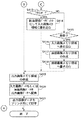
以下、本発明の実施の形態に係る画像形成システムの作動を図4及び図5を参照して説明する。
【0037】
図4及び図5は、本発明の実施の形態に係る画像形成システムの作動のフローチャートである。
【0038】
本実施の形態に係る画像形成システムでは、実行可能な動作モードとして、通常のコピーモードや、両面印刷モード等の他に、4連ハガキ印刷モードを有しており、操作部150等において、ユーザがこれらの中から所望のモードを選択可能するよう構成されている。以下に、4連ハガキ印刷モードを実行する場合の説明を行う。
【0039】
まず、ユーザは、原稿となる官製ハガキサイズの用紙をプラテンガラス211に載せ、記録紙となる4連ハガキ専用シートをカセット311にセットする。
【0040】
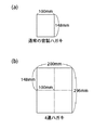
上記4連ハガキ専用シートとは、図6に示すように、通常の市販されている通常の官製ハガキ(図6(a))4枚分の大きさをもつサイズのシート(図6(b))であり、縦方向に通常の官製ハガキの2枚分の大きさを持ち、横方向にも通常の官製ハガキの2枚分の大きさを有している。1枚の官製ハガキのサイズは、シートの短辺方向の長さが約100mmでシートの長辺方向の長さが約148mmとする。従って、4連ハガキ専用シートのサイズは、シートの短辺方向の長さが200mmで、シートの長辺方向の長さが296mmである。又、シートの厚さに関しては、通常の官製ハガキと同様である。即ち、普通紙よりも厚い厚紙である。そして、これらの4分割された領域の、夫々の領域に、例えば、同一の画像が形成される。尚、図6(b)に示す4連ハガキ専用シートは、画像形成ジョブが終了した後に、ユーザ或いは機械が当該シートを4分割に断裁する為の目安として、予め当該シート上に破線が付加されている。尚、このような4連ハガキ専用シートでなくても(例えば、厚紙ではない通常の普通紙や、破線が付加されていないシート等)、当該シートに相当するサイズ(296mm×200mm)のシートであれば、4連ハガキ印刷モードを許可するものとする。
【0041】
図4において、図7の画面より「4連ハガキ印刷」を選択して4連ハガキを設定すると(ステップS401)(選択手段)、操作部150の画面は図8に示すようになる。図7及び図8は、これらの移行表示の一例であり、これに限定されるものではない。
【0042】
「4連ハガキ印刷」選択時、ステイプル機能やパンチ穴機能を誤って使用しないよう、夫々の機能を使用不可(OFF)にする(ステップS402)(制御手段)。この場合、シートの仕分け機能は選択禁止状態にすることなく、選択可能状態のままである。図7の画面では、ステイプル機能やパンチ穴機能の設定項目が選択禁止状態になっている。例えば、ステイプル機能やパンチ機能等の機能ボタンを破線表示や、グレー表示、綱掛け表示等にし、ユーザがこれらの機能ボタンを押下しても、何にも反応しない無効状態にして(つまり、選択禁止状態)にする。一方、シートの仕分け機能は、実線表示のままであり、有効状態(つまり、選択可能状態のまま)である。
【0043】
本実施の形態において、上述したような制御を何故おこなうのかその理由に関し、以下に述べる。まず、本実施の形態における4連ハガキ専用シート(或いは、当該シートのサイズに相当するサイズのシート)は、図6及び上述の説明でも述べたように、通常の記録紙とはタイプ(例えば、サイズや厚さ等)の異なるシートである。このような特異なタイプのシートに対してステイプル処理やパンチ処理を行うことは制御が困難であり、又、当該処理を行うためのユニットの故障の原因となりうる可能性も考えられる。そして、なによりも、当該シートは、画像形成後、ユーザによる手作業や、機械による断裁作業により、4枚のシートに分割され、年賀状や手紙等のハガキとして利用することを目的とするシートである。このような目的のシートに対してステイプル処理やパンチ処理等の紙加工処理を行ってしまっては、使い物にならず、資源の無駄遣いとなってしまう。このような理由を考慮して、上述のような制御を行っている。これにより、ユーザが誤ってステイプル処理やパンチ処理等のシートに対する紙加工処理を実行するためのボタンを押下してしまう等のユーザによる誤操作を未然に防止できる。尚且つ、ユーザはこれらのボタンを押下しなくても、自動的にステイプル処理やパンチ処理等のシート加工処理が行われてしまう等の不具合が生じることを防止できる。
【0044】
次いで、図8の画面のスタートボタンを押下することにより(ステップS403)、以下の一連の動作の原稿画像の読取りが開始される(ステップS404〜S408)。
【0045】
まず、ステップS404では、給紙ユニットに4連ハガキ専用シートがあるか否かを判別し(記録紙サイズ検知手段)、なければ、本処理を終了する一方、あれば、給紙ユニット上の原稿サイズを検知して(ステップS405)、適切な原稿サイズか否かを判別する(ステップS406)。ステップS406の判別の結果、適切なサイズでなければ、本処理を終了する一方、適切なサイズであれば、原稿の画像を読取り(ステップS407)(画像データ入力手段)、原稿となる完成ハガキを読取る際、制御装置110は読取り画像用の入力画像メモリ領域を作成してそこに読取り画像データを格納する(ステップS408)。
【0046】
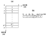
ステップS409では、図8の画面で「マスキング」「トリミング」「移動」等のモード設定がなされたか否かを判別し、モード設定がなされていなければ、読取り画像データを入力画像メモリ領域へ書き込んだ(ステップS410)後、出力画像メモリ領域を作成する(ステップS419)。ここで、原稿の官製ハガキのサイズが主走査方向xdot、副走査方向のydotとすると、上記入力画像メモリ領域の大きさは、xy(bit)であり(図13)、また、4連ハガキ専用シートの主走査方向、副走査方向のサイズは夫々2xdot、2ydotとなるので、上記出力画像メモリ領域のサイズは、4xy(bit)となる(図14)。
【0047】
次いで、入力画像メモリ内容及び出力画像メモリ内容についてx(bit)を主走査単位領域として、入力画像メモリ主走査単位領域1カ所につき出力画像メモリ主走査単位領域の4カ所へ画像データを変換してコピーする(ステップS420)(画像データ変換手段)。詳細を図15に示す。入力画像メモリ主走査単位領域(xbit)ごとに先頭からN(1),N(2),N(3),・・・N(y−1),N(y)とする。出力画像メモリ主走査単位領域(xbit)も同様に先頭からS(1),S(2),S(3),・・・S(4y−1),S(4y)とする。入力画像メモリ主走査単位領域N(1)の内容は、出力画像メモリ主走査単位領域S(1),S(2),S(2y+1),S(2y+2)へコピーされる。次に入力画像メモリ主走査単位領域N(2)は、出力画像メモリ主走査単位領域S(3),S(4),S(2y+3),S(2y+4)へコピーし以下同様に入力画像メモリ主走査単位領域N(y)が出力画像メモリ主走査単位領域S(2y−1),S(2y),S(4y−1),S(4y)へコピーするまで繰り返す。
【0048】
出力画像メモリへのコピーが完了したら、制御装置110からプリンタ部300へ出力画像データとして出力画像メモリ内容を伝送し、プリンタ部300にて4連ハガキ専用シートへ印字を行う(ステップS421)(画像データ出力手段)。
【0049】
印字後、4連ハガキ専用シートは排紙ユニット330へ搬送される。そして、4連ハガキ専用シートが複数部あるような場合等は、シート処理装置としての仕分け部330にて、プリンタ部本体から排出された4連ハガキ専用シートを束ねて仕分けする(例えば、シートの整合処理や、複数のビンを有する不図示のソータ等や、複数ページからなるシート群(1部)を各部毎にずらした状態で積載トレイに積載するよう、シートの束排出動作等により、ソートモードやグループソートとしての、シートの仕分け処理を行なう。)が、不図示のステイプラによりステイプルを行ったり不図示のパンチユニットによりパンチ穴を空ける処理(穿孔処理)を実行することを禁止するよう各ユニットを制御する。
【0050】
尚、上述のシート仕分け処理に関しては、不図示のカウンタによりカウントされるシートの出力枚数情報や、操作部から入力される設定部数情報等に応じて、装置が独自の判断で自動で行っても良いし、例えば、上述の図7に示す画面等を用いて、ユーザがシートの仕分けに関する設定を行い、それに応じて装置がユーザの所望の仕分け処理を実行するような構成でもよい。
【0051】
このように、画像形成すべきシートの種類が4連ハガキ専用シートであることに応じて(操作部150にてユーザにより設定された動作モードが4連ハガキ印刷モードであることに応じて)、ステイプルユニットによるステイプル処理、パンチユニットによる穴あけ処理等の、当該シートに対する加工処理を行なうことを禁止する(例えば、操作部上の該当する機能ボタンを網掛け表示し、ユーザが押下しても反応しない、無効状態にする等)と共に、4連ハガキ専用シートが複数部出力されるような場合におけるシートの整合性、積載性等を考慮して、シートの仕分け処理等を実行することは許可する(例えば、操作部上でユーザにより、4連ハガキ印刷モードが選択されたとしても、操作部上の該当するモードの機能ボタンを有効状態にしたり、設定枚数、部数等に基づいて、自動的に仕分けモードを実行する等)。
【0052】
ステップS409〜S414の処理では、官製ハガキの切手が印刷されている領域や年賀状などにおいて抽選番号などが記載されている領域等の特定矩形領域(指定領域)の画像の入力を禁止したり、その反対に指定領域のみの画像を入力する。
【0053】
ステップS409の判別の結果、「マスキング」を選択した場合、即ち画像入力しない特定矩形領域(指定領域)を設定する場合は(ステップS411でYES)、該当領域以外のデータビットを「0」にして入力画像領域に書き込んだ(ステップS412)後、「トリミング」を設定した場合、即ち指定領域のみ画像入力する設定をする場合は(ステップS413でYES)、該当領域データビットを、データがないことを示す「0」として入力画像メモリ領域に書き込んだ(ステップS414)後、ステップS419に進み、上記ステップS419〜S421の処理を実行する。
【0054】
上記において、「マスキング」を選択した場合(ステップS411でYES)を例にとって詳細に説明する。
【0055】
この指定領域データは、予め機器に登録されていたり、ユーザが自由に設定できたりすることが可能である。ユーザが設定する場合、図9の画面で「ユーザ設定」項目を選択することで、領域指定画面が現れ(図10)、任意の2点間で囲まれた矩形領域を複数設定が出来る。この「マスキング」の例として、切手領域を「マスキング」するユーザ設定例を説明する。図16のように切手領域としてA0(0,0),A1(m,n)で囲まれた矩形領域を指定するために、図10にある左上座標x,yを共に0に、右下座標x,yを夫々m,nと指定する。OKボタンを押下することでこの領域をマスキング指定領域として登録される。図9、図10は、これらの意向表示の一例であり、これに限定されるものではない。
【0056】
上記において、指定されたマスキング領域では、印字の際に何も出力されない。また、トリミング領域の場合、この領域に該当する画像データビットは入力画像メモリに依存し、この領域以外に該当する画像データビットは「0」となる。
【0057】
さらに、ステップS415〜S418の処理では、原稿画像データを読取り後、そのデータをハガキの指定位置に設定する。
【0058】
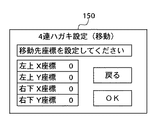
ステップS409の判別の結果、図8の画面で、「移動」を選択した場合は(ステップS415でYES)、図11の画面で、移動元原稿画像領域としてA0(0,0)、A1(m,n)で囲まれた矩形領域を選択し、図12の画面で、移動先原稿位置としてその原稿画像の左上をA2(x2,y2)のようにハガキ1枚サイズのどの位置に設定したいかを指定する。このとき、設定した原稿画像がハガキ1枚サイズ領域外になった場合は、その部分の画像データは無視する。図11、図12は、これらの意向表示の一例であり、これに限定されるものではない。
【0059】
図17のように移動元原稿サイズが主走査方向mdot、副走査方向ndotとすると、入力画像メモリ領域の大きさはmn(bit)となる。入力画像メモリ主走査単位領域(mbit)ごとに先頭からN(1),N(2),N(3),・・・N(n−1),N(n)とする。
【0060】
原稿画像の読取りが終了すると制御装置内部において、主走査方向xdot、副走査方向ydotなるハガキサイズの原稿画像メモリ領域を作成し(ステップS417)、原稿画像メモリ主走査単位領域(xbit)ごとに先頭からG(1),G(2),G(3),・・・G(n−1),G(n)とする。方法として、N(1)領域をG(y2+1)領域の先頭からx2bitずらした位置よりmbitサイズ分入力画像を原稿画像へコピーする(ステップS418)。このときx2+mの値が原稿画像主走査単位(xbit)よりも大きい場合、xより大きい部分はコピーしない。同様に次のN(2)領域はG(y2+2)領域の先頭からx2bitずらした位置よりmbitサイズ分コピーしていき、N(n)領域がG(y2+n)領域の先頭からx2bitずらした位置よりmbitサイズ分コピーするまで繰り返す(図18)。
【0061】
上記のように原稿画像メモリ領域へのコピーが終了すると、ステップS419に進み、上記ステップS419〜S421の処理を実行する。
【0062】
尚、本実施の形態では、生産性を向上させるべく、4連ハガキ用のシートを使用することで、一度に4枚分の出力結果を得るように構成しているが、4連ハガキ用シートよりも大きい、例えば、8連ハガキ用シート、16連ハガキシート等の、少なくとも通常の官製はがき2枚分以上のサイズのシートの同一面上に複数の画像を配置して像形成するような構成でも本実施の形態は適用可能である。
【0063】
又、本実施の形態で述べた処理(機能)を実現するためのプログラムは、ROM114にプログラムコードとして記憶されており、CPU112が該コードを読み出してその機能を実行するものとするが、本実施の形態の機能を実現するソフトウェアのプログラムコードを記録した記憶媒体を、システムあるいは装置に供給し、そのシステムあるいは装置のコンピュータ(またはCPUやMPU)が記憶媒体に格納されたプログラムコードを読出し実行することによっても、達成されることは言うまでもない。
【0064】
この場合、記憶媒体から読出されたプログラムコード自体が前述した実施の形態の機能を実現することにより、そのプログラムコードを記憶した記憶媒体は本発明を構成することになる。
【0065】
プログラムコードを供給するための記憶媒体としては、例えば、フロッピディスク、ハードディスク、光ディスク、光磁気ディスク、CD−ROM、CD−R、磁気テープ、不揮発性のメモリカード、ROMなどを用いることができる。
【0066】
又、コンピュータが読出したプログラムコードを実行することにより、前述した実施の形態の機能が実現されるだけでなく、そのプログラムコードの指示に基づき、コンピュータ上で稼働しているOS(オペレーティングシステム)などが実際の処理の一部または全部を行い、その処理によって前述した実施形態の機能が実現される場合も含まれることは言うまでもない。
【0067】
更に、記憶媒体から読出されたプログラムコードがコンピュータに挿入された機能拡張ボードやコンピュータに接続された機能拡張ユニットに備わるメモリに書き込まれた後、そのプログラムコードの指示に基づき、その機能拡張ボードや機能拡張ユニットに備わるCPUなどが実際の処理の一部または全部を行い、その処理によって前述した実施形態の機能が実現される場合も含まれることは言うまでもない。
【0068】
【発明の効果】
以上説明したように、本発明によれば、同一面上に複数の同一画像が形成されたシート対して加工処理が実行されてしまうことを防止することができる。
【図面の簡単な説明】
【図1】 本発明の実施の形態に係る画像形成システムの全体構成を示すブロック図である。
【図2】 図1におけるリーダー部200及びプリンタ部300の断面図である。
【図3】 図1における制御装置110の構成を示すブロック図である。
【図4】 本発明の実施の形態に係る画像形成システムの作動を示すフローチャートである。
【図5】 本発明の実施の形態に係る画像形成システムの作動を示すフローチャートである。
【図6】 (a)は通常のハガキの説明図、(b)は4連ハガキの説明図である。
【図7】 図1における操作部150の表示の一例を示す図である。
【図8】 図1における操作部150の表示の一例を示す図である。
【図9】 図1における操作部150の表示の一例を示す図である。
【図10】 図1における操作部150の表示の一例を示す図である。
【図11】 図1における操作部150の表示の一例を示す図である。
【図12】 図1における操作部150の表示の一例を示す図である。
【図13】 (a)は、入力画像メモリ領域の説明図であり、(b)は、同入力画像メモリの説明図である。
【図14】 (a)は、出力画像メモリ領域の説明図であり、(b)は、同出力画像メモリの説明図である。
【図15】 入力画像メモリから出力画像メモリへの変換を説明する図であり、(a)は入力画像メモリ、(b)は出力画像メモリの説明図である。
【図16】 (a)は、マスキング設定時の印刷対象外指定領域の説明図であり、(b)は、同入力画像メモリの説明図である。
【図17】 (a)は、移動設定時の移動元原稿画像領域の説明図であり、(b)は、同入力画像メモリの説明図である。
【図18】(a)は、移動設定時の移動先原稿画像領域の説明図であり、(b)は、同入力画像メモリの説明図である。
【符号の説明】
110 制御装置
150 操作部
200 リーダ部
210 スキャナユニット
250 原稿給紙ユニット
300 プリンタ部
310 給紙ユニット
330 排紙ユニット
400 LANユニット[0001]
BACKGROUND OF THE INVENTION
The present invention relates to an image forming apparatus that forms an image on a sheet, a control method for the image forming apparatus, and an image forming system.
[0002]
[Prior art]
In recent years, as image forming systems are digitized, it has become possible to output images by various methods. For example, in addition to a function of reading only a desired portion of a document such as a trimming function and a function of not reading only a desired portion of a document such as a masking function, a single document image is read such as an image repeat function. It is possible to output the image to several places on one output sheet. Further, even when a large amount of one document is output, only one reading is required. An image forming system having a punching function for punching a recording paper and a stapling function for stapling the recording paper is also being proposed.
[0003]
[Problems to be solved by the invention]
However, when printing a large number of postcards, it takes a long time to print one by one. Further, when the punch function and the staple function are automatically set, even if the recording paper size is not desired, it may be automatically executed if the recording paper size is equal to or larger than a predetermined size. Further, if the punch function or the staple function is not used, the user has to manually set the functions so as not to be selected.
[0004]
An object of the present invention is to save printing time when printing a postcard, to prevent a user's erroneous operation, and to prevent an output product unintended by the user from being generated. The present invention provides an image forming apparatus, an image forming apparatus control method, and an image forming system.
[0005]
[Means for Solving the Problems]
In order to achieve the above object, an image forming apparatus of the present invention is an image forming apparatus, and forms an image on a sheet based on input means for inputting image data and image data input by the input means. An image forming unit, a processing unit that performs processing on a sheet on which an image is formed by the image forming unit, a first function that forms a plurality of identical images on the same surface of the sheet, and the processingmeansSelecting means for selecting at least one of a plurality of functions including the second function for executing the processing process according to the operator, and the image forming means and the processing means according to the function selected by the selection means. Control means for controlling each of the control means, and when the selection means selects the first function, the control means uses the processing means.SaidControl is performed to disable the processing.
[0006]
In order to achieve the above object, an image forming apparatus of the present invention is an image forming apparatus, and forms an image on a sheet based on input means for inputting image data and image data input by the input means. An image forming unit; a stapling unit that performs a stapling process on a sheet on which an image is formed by the image forming unit; a first function that forms a plurality of the same images on the same surface of the sheet; and the stapling unit by the stapling unit A selection unit that selects at least one of a plurality of functions including a second function that executes processing according to an instruction from an operator, and controls the image forming unit and the staple processing unit according to the function selected by the selection unit, respectively. Control means, and when the selection means selects the first function, the control means And controlling so as to disable the stapling process by the management unit.
[0007]
In order to achieve the above object, an image forming apparatus of the present invention is an image forming apparatus, and forms an image on a sheet based on input means for inputting image data and image data input by the input means. An image forming unit; a punch processing unit that performs punch processing on a sheet on which an image is formed by the image forming unit; a first function that forms a plurality of identical images on the same surface of the sheet; and the punch by the punch processing unit A selection unit that selects at least one of a plurality of functions including a second function that executes processing according to an operator's instruction, and controls the image forming unit and the punch processing unit according to the function selected by the selection unit, respectively. Control means, and when the selection means selects the first function, the control means performs the punching by the punch processing means. And controlling to the physical unusable.
[0008]
In order to achieve the above object, an image forming apparatus control method according to the present invention includes an input unit for inputting image data, and an image forming unit for forming an image on a sheet based on the image data input by the input unit. , A control method for an image forming apparatus having a processing means for processing a sheet on which an image is formed by the image forming means, wherein the selecting means forms a plurality of the same images on the same surface of the sheet First function and the processingmeansA selection step of selecting at least one of a plurality of functions including the second function for executing the processing process according to the instruction according to an instruction of an operator of the image forming apparatus, and the image forming means according to the function selected by the selection step And a control step for controlling each of the processing means, and the control step is performed by the processing means when the selection step selects the first function.SaidControl is performed to disable the processing.
[0009]
In order to achieve the above object, an image forming system of the present invention includes an input unit that inputs image data, an image forming unit that forms an image on a sheet based on the image data input by the input unit, and the image An image forming system having an image forming apparatus including a processing unit that performs processing on a sheet on which an image is formed by a forming unit, the first function for forming a plurality of identical images on the same surface of the sheet, and ProcessingmeansSelecting means for selecting at least one of a plurality of functions including the second function for executing the processing process according to the operator, and the image forming means and the processing means according to the function selected by the selection means. Control means for controlling each of the control means, and when the selection means selects the first function, the control means uses the processing means.SaidControl is performed to disable the processing.
[0010]
DETAILED DESCRIPTION OF THE INVENTION
An overall configuration of an image forming system according to an embodiment of the present invention will be described with reference to the drawings.
[0011]
FIG. 1 is a diagram showing an overall configuration of an image forming system according to an embodiment of the present invention.
[0012]
In FIG. 1, the
[0013]
The
[0014]
The
[0015]
The
[0016]
The
[0017]
The
[0018]
FIG. 2 is a cross-sectional view of the
[0019]
A
[0020]
FIG. 3 is a block diagram illustrating a configuration of the
[0021]
The
[0022]
The
[0023]
The
[0024]
The
[0025]
An
[0026]
The I /
[0027]
The panel I /
[0028]
The
[0029]
The real
[0030]
The
[0031]
The
[0032]
The scanner I /
[0033]
Data transfer from the
[0034]
The printer I /
[0035]
The transfer of the raster image data developed on the
[0036]
The operation of the image forming system according to the embodiment of the present invention will be described below with reference to FIGS.
[0037]
4 and 5 are flowcharts of the operation of the image forming system according to the embodiment of the present invention.
[0038]
In the image forming system according to the present embodiment, as an executable operation mode, in addition to a normal copy mode, a double-sided printing mode, and the like, a quadruple postcard printing mode is provided. Are configured so that a desired mode can be selected from these modes. The following describes the case where the quad postcard printing mode is executed.
[0039]
First, the user places a public postcard size paper to be a manuscript on the
[0040]
As shown in FIG. 6, the above-mentioned four-postcard-dedicated sheet is a sheet of a size that is equivalent to four sheets of a normal commercially available postcard (FIG. 6A) (FIG. 6B). ), And has a size corresponding to two normal government-made postcards in the vertical direction, and also has a size corresponding to two normal government-made postcards in the horizontal direction. The size of one government postcard is about 100 mm in the short side direction of the sheet and about 148 mm in the long side direction of the sheet. Therefore, as for the size of the sheet for quadruple postcards, the length in the short side direction of the sheet is 200 mm, and the length in the long side direction of the sheet is 296 mm. Further, the thickness of the sheet is the same as that of a normal public postcard. That is, the thick paper is thicker than plain paper. Then, for example, the same image is formed in each of these four divided areas. Note that the four-postcard dedicated sheet shown in FIG. 6B has a broken line added to the sheet in advance as a guide for the user or machine to cut the sheet into four parts after the image forming job is completed. ing. In addition, even if it is not such a quadruple postcard dedicated sheet (for example, normal plain paper that is not thick paper, or a sheet without a broken line added), it is a sheet of a size (296 mm × 200 mm) corresponding to the sheet. If there is, the four-card postcard printing mode is permitted.
[0041]
In FIG. 4, when “4-strip postcard printing” is selected from the screen of FIG. 7 and 4-strip postcards are set (step S <b> 401) (selecting means), the screen of the
[0042]
When “quadruple printing” is selected, the respective functions are disabled (OFF) so that the staple function and punch hole function are not used by mistake (step S402) (control means). In this case, the sheet sorting function remains in a selectable state without being in a selection prohibited state. In the screen of FIG. 7, the setting items for the staple function and the punch hole function are in a selection-prohibited state. For example, the function buttons for the staple function, punch function, etc. are displayed in broken lines, grayed out, rope display, etc., and even if the user presses these function buttons, they are in an invalid state (that is, selected) (Prohibited state). On the other hand, the sheet sorting function remains in a solid line display and is in a valid state (that is, in a selectable state).
[0043]
The reason why the above-described control is performed in this embodiment will be described below. First, as described in FIG. 6 and the above description, the four postcard-dedicated sheet (or a sheet corresponding to the size of the sheet) in this embodiment is a type (for example, Sheets with different sizes and thicknesses. It is difficult to control the stapling process or the punching process for such a specific type of sheet, and there is a possibility that a unit for performing the process may be damaged. Above all, after the image is formed, the sheet is divided into four sheets by a user's manual operation or a cutting operation by a machine, and is a sheet intended to be used as a postcard such as a New Year's card or a letter. is there. If paper processing such as stapling or punching is performed on such a target sheet, the sheet is not used and wastes resources. In consideration of such a reason, the control as described above is performed. Accordingly, it is possible to prevent an erroneous operation by the user such as a user erroneously pressing a button for executing a paper processing process on a sheet such as a stapling process or a punching process. In addition, even if the user does not press these buttons, it is possible to prevent a problem such as a sheet processing process such as a stapling process or a punching process from being automatically performed.
[0044]
Next, when the start button on the screen of FIG. 8 is pressed (step S403), reading of a document image in the following series of operations is started (steps S404 to S408).
[0045]
First, in step S404, it is determined whether or not there is a quadruple postcard dedicated sheet in the paper feed unit (recording paper size detecting means). If not, the process ends. The size is detected (step S405), and it is determined whether the document size is appropriate (step S406). If the result of determination in step S406 is that the size is not appropriate, the present process is terminated. If the size is appropriate, the image of the document is read (step S407) (image data input means), and the completed postcard as the document is read. When reading, the
[0046]
In step S409, it is determined whether or not mode settings such as “masking”, “trimming”, and “move” have been made on the screen of FIG. 8. If no mode has been set, read image data is written into the input image memory area. After (Step S410), an output image memory area is created (Step S419). Here, assuming that the size of the postcard made by the manuscript is xdot in the main scanning direction and ydot in the sub-scanning direction, the size of the input image memory area is xy (bit) (FIG. 13). Since the sizes of the main scanning direction and the sub-scanning direction of the sheet are 2xdot and 2ydot, respectively, the size of the output image memory area is 4xy (bit) (FIG. 14).
[0047]
Next, with respect to the input image memory contents and the output image memory contents, x (bit) is set as the main scanning unit area, and the image data is converted into four places in the output image memory main scanning unit area for each input image memory main scanning unit area. Copy (step S420) (image data conversion means). Details are shown in FIG. N (1), N (2), N (3),... N (y−1), N (y) from the head for each input image memory main scanning unit area (xbit). Similarly, the output image memory main scanning unit area (xbit) is set to S (1), S (2), S (3),... S (4y-1), S (4y) from the top. The contents of the input image memory main scanning unit area N (1) are copied to the output image memory main scanning unit area S (1), S (2), S (2y + 1), S (2y + 2). Next, the input image memory main scanning unit area N (2) is copied to the output image memory main scanning unit area S (3), S (4), S (2y + 3), S (2y + 4), and so on. The process is repeated until the main scanning unit area N (y) is copied to the output image memory main scanning unit area S (2y-1), S (2y), S (4y-1), S (4y).
[0048]
When the copying to the output image memory is completed, the contents of the output image memory are transmitted as output image data from the
[0049]
After printing, the four-postcard dedicated sheet is conveyed to the
[0050]
Note that the sheet sorting process described above may be automatically performed by the apparatus based on its own judgment according to information on the number of output sheets counted by a counter (not shown), information on the number of copies set from the operation unit, and the like. Alternatively, for example, a configuration in which the user performs settings relating to sheet sorting using the screen illustrated in FIG. 7 described above, and the apparatus executes a user's desired sorting process in response thereto may be used.
[0051]
As described above, according to the type of the sheet to be imaged being a quadruple postcard dedicated sheet (according to the operation mode set by the user in the
[0052]
In the processing of steps S409 to S414, it is prohibited to input an image of a specific rectangular area (designated area) such as an area where a public postcard stamp is printed or an area where a lottery number is written on a New Year's card or the like. On the contrary, an image of only the designated area is input.
[0053]
If “masking” is selected as a result of the determination in step S409, that is, if a specific rectangular area (designated area) where no image is input is set (YES in step S411), data bits other than the corresponding area are set to “0”. When “trimming” is set after writing in the input image area (step S412), that is, when setting the image input only in the specified area (YES in step S413), the corresponding area data bit is set to indicate that there is no data. After writing in the input image memory area as “0” (step S414), the process proceeds to step S419, and the processes of steps S419 to S421 are executed.
[0054]
In the above, the case where “masking” is selected (YES in step S411) will be described in detail.
[0055]
The designated area data can be registered in advance in the device or can be freely set by the user. When the user sets, by selecting the “user setting” item on the screen of FIG. 9, an area designation screen appears (FIG. 10), and a plurality of rectangular areas surrounded by any two points can be set. As an example of this “masking”, a user setting example for “masking” a stamp area will be described. As shown in FIG. 16, in order to specify a rectangular area surrounded by A0 (0, 0) and A1 (m, n) as stamp areas, both the upper left coordinates x and y in FIG. Designate x and y as m and n, respectively. This area is registered as a masking designation area by pressing the OK button. 9 and 10 are examples of these intention displays, and the present invention is not limited to them.
[0056]
In the above, nothing is output during printing in the designated masking area. In the case of a trimming area, image data bits corresponding to this area depend on the input image memory, and image data bits corresponding to areas other than this area are “0”.
[0057]
Further, in the processing of steps S415 to S418, after reading the document image data, the data is set at a designated postcard position.
[0058]
As a result of the determination in step S409, if “Move” is selected on the screen of FIG. 8 (YES in step S415), A0 (0, 0), A1 (m) are selected as the source document image areas on the screen of FIG. , N) is selected, and in the screen of FIG. 12, the position of the postcard size to be set to the upper left of the original image as A2 (x2, y2) is set as the movement destination original position. Is specified. At this time, if the set document image is outside the postcard size area, the image data of that portion is ignored. 11 and 12 are examples of these intention displays, and the present invention is not limited to these.
[0059]
As shown in FIG. 17, when the size of the source document is mdot in the main scanning direction and ndot in the sub scanning direction, the size of the input image memory area is mn (bit). N (1), N (2), N (3),... N (n−1), N (n) from the head for each input image memory main scanning unit area (mbit).
[0060]
When reading of the document image is completed, a postcard-sized document image memory area having a main scanning direction xdot and a sub-scanning direction ydot is created in the control device (step S417), and the head of each document image memory main scanning unit area (xbit) is created. To G (1), G (2), G (3),... G (n−1), G (n). As a method, the input image is copied to the original image by the mbit size from the position where the N (1) area is shifted by x2 bits from the head of the G (y2 + 1) area (step S418). At this time, if the value of x2 + m is larger than the original image main scanning unit (xbit), the portion larger than x is not copied. Similarly, the next N (2) area is copied by the mbit size from the position shifted by x2 bits from the head of the G (y2 + 2) area, and the N (n) area is copied by x2 bits from the head of the G (y2 + n) area. Repeat until copying for mbit size (FIG. 18).
[0061]
When copying to the document image memory area is completed as described above, the process proceeds to step S419, and the processes of steps S419 to S421 are executed.
[0062]
In this embodiment, in order to improve the productivity, the four-postcard sheet is used to obtain the output result for four sheets at a time. However, the four-postcard sheet is used. Larger than, for example, 8 postcard sheets, 16 continuous postcard sheets, etc., and at least two normal government postcards or more sheets are arranged on the same surface to form an image. However, this embodiment can be applied.
[0063]
A program for realizing the processing (function) described in the present embodiment is stored as a program code in the
[0064]
In this case, the program code itself read from the storage medium realizes the functions of the above-described embodiments, so that the storage medium storing the program code constitutes the present invention.
[0065]
As a storage medium for supplying the program code, for example, a floppy disk, a hard disk, an optical disk, a magneto-optical disk, a CD-ROM, a CD-R, a magnetic tape, a nonvolatile memory card, a ROM, or the like can be used.
[0066]
Further, by executing the program code read by the computer, not only the functions of the above-described embodiments are realized, but also an OS (operating system) running on the computer based on the instruction of the program code However, it is needless to say that some or all of the actual processing is performed and the functions of the above-described embodiments are realized by the processing.
[0067]
Furthermore, after the program code read from the storage medium is written in a memory provided in a function expansion board inserted into the computer or a function expansion unit connected to the computer, the function expansion board or It goes without saying that the CPU or the like provided in the function expansion unit performs part or all of the actual processing and the functions of the above-described embodiments are realized by the processing.
[0068]
【The invention's effect】
As described above, according to the present invention, it is possible to prevent a processing process from being performed on a sheet on which a plurality of identical images are formed on the same surface.
[Brief description of the drawings]
FIG. 1 is a block diagram showing an overall configuration of an image forming system according to an embodiment of the present invention.
2 is a cross-sectional view of a
FIG. 3 is a block diagram showing a configuration of a
FIG. 4 is a flowchart showing an operation of the image forming system according to the embodiment of the present invention.
FIG. 5 is a flowchart showing an operation of the image forming system according to the embodiment of the present invention.
6A is an explanatory diagram of a normal postcard, and FIG. 6B is an explanatory diagram of a quadruple postcard.
7 is a diagram showing an example of a display on the
8 is a diagram showing an example of a display on the
FIG. 9 is a diagram illustrating an example of a display on the
10 is a diagram showing an example of a display on the
11 is a diagram showing an example of a display on the
12 is a diagram showing an example of a display on the
FIG. 13A is an explanatory diagram of an input image memory area, and FIG. 13B is an explanatory diagram of the input image memory.
14A is an explanatory diagram of an output image memory area, and FIG. 14B is an explanatory diagram of the output image memory.
15A and 15B are diagrams for explaining conversion from an input image memory to an output image memory, in which FIG. 15A is an input image memory, and FIG. 15B is an explanatory diagram of an output image memory.
FIG. 16A is an explanatory diagram of a non-printable designation area when masking is set, and FIG. 16B is an explanatory diagram of the input image memory.
FIG. 17A is an explanatory diagram of a source document image area at the time of movement setting, and FIG. 17B is an explanatory diagram of the input image memory.
18A is an explanatory diagram of a destination document image area at the time of movement setting, and FIG. 18B is an explanatory diagram of the input image memory.
[Explanation of symbols]
110 Control device
150 Operation unit
200 Reader section
210 Scanner unit
250 Document feeder
300 Printer section
310 Paper Feed Unit
330 Paper discharge unit
400 LAN unit
Claims (10)
画像データを入力する入力手段と、
前記入力手段により入力された画像データに基づいてシートに画像を形成する画像形成手段と、
前記画像形成手段により画像が形成されたシートに対する加工処理を行う加工処理手段と、
シートの同一面上に複数の同一画像を形成する第1機能及び前記加工処理手段による前記加工処理を実行する第2機能を含む複数の機能の少なくともいずれかを、操作者の指示に従って選択する選択手段と、
前記選択手段が選択した機能に従って前記画像形成手段及び前記加工処理手段をそれぞれ制御する制御手段とを有し、
前記制御手段は、前記選択手段が前記第1機能を選択する場合は前記加工処理手段による前記加工処理を使用不可とするよう制御することを特徴とする画像形成装置。An image forming apparatus,
Input means for inputting image data;
Image forming means for forming an image on a sheet based on the image data input by the input means;
Processing means for processing the sheet on which an image is formed by the image forming means;
Selection for selecting at least one of a plurality of functions including a first function for forming a plurality of the same images on the same surface of the sheet and a second function for executing the processing by the processing means according to an instruction of the operator Means,
Control means for controlling the image forming means and the processing means according to the function selected by the selection means,
It said control means, the image forming apparatus when said selecting means selects said first function, wherein the controller controls so as to disable the processing by the processing means.
画像データを入力する入力手段と、 Input means for inputting image data;
前記入力手段により入力された画像データに基づいてシートに画像を形成する画像形成手段と、 Image forming means for forming an image on a sheet based on the image data input by the input means;
前記画像形成手段により画像が形成されたシートに対するステイプル処理を行うステイプル処理手段と、 Stapling processing means for performing stapling processing on a sheet on which an image is formed by the image forming means;
シートの同一面上に複数の同一画像を形成する第1機能及び前記ステイプル処理手段による前記ステイプル処理を実行する第2機能を含む複数の機能の少なくともいずれかを、操作者の指示に従って選択する選択手段と、 Selection for selecting at least one of a plurality of functions including a first function for forming a plurality of identical images on the same surface of a sheet and a second function for executing the stapling process by the stapling means according to an operator's instruction Means,
前記選択手段が選択した機能に従って前記画像形成手段及び前記ステイプル処理手段をそれぞれ制御する制御手段とを有し、 Control means for controlling the image forming means and the staple processing means according to the function selected by the selection means,
前記制御手段は、前記選択手段が前記第1機能を選択する場合は前記ステイプル処理手段による前記ステイプル処理を使用不可とするよう制御することを特徴とする画像形成装置。 The image forming apparatus according to claim 1, wherein when the selection unit selects the first function, the control unit performs control so that the stapling processing by the stapling processing unit is disabled.
画像データを入力する入力手段と、 Input means for inputting image data;
前記入力手段により入力された画像データに基づいてシートに画像を形成する画像形成手段と、 Image forming means for forming an image on a sheet based on the image data input by the input means;
前記画像形成手段により画像が形成されたシートに対するパンチ処理を行うパンチ処理手段と、 Punch processing means for performing punch processing on a sheet on which an image is formed by the image forming means;
シートの同一面上に複数の同一画像を形成する第1機能及び前記パンチ処理手段による前記パンチ処理を実行する第2機能を含む複数の機能の少なくともいずれかを、操作者の指示に従って選択する選択手段と、 Selection for selecting at least one of a plurality of functions including a first function for forming a plurality of identical images on the same surface of a sheet and a second function for executing the punching process by the punching unit according to an instruction of an operator Means,
前記選択手段が選択した機能に従って前記画像形成手段及び前記パンチ処理手段をそれぞれ制御する制御手段とを有し、 Control means for controlling the image forming means and the punch processing means according to the function selected by the selection means,
前記制御手段は、前記選択手段が前記第1機能を選択する場合は前記パンチ処理手段による前記パンチ処理を使用不可とするよう制御することを特徴とする画像形成装置。 The image forming apparatus according to claim 1, wherein the control unit controls the punch processing by the punch processing unit to be unusable when the selection unit selects the first function.
前記複数の機能は、前記画像形成手段により画像が形成されたシートを仕分けする第3機能を含み、
前記制御手段は、前記選択手段が前記第1機能を選択する場合は前記仕分け手段によるシートの仕分けを行わないよう制御することを特徴とする請求項1乃至4のいずれか1項に記載の画像形成装置。Sorting means for sorting sheets on which images are formed by the image forming means;
The plurality of functions include a third function for sorting sheets on which images are formed by the image forming unit,
5. The image according to claim 1, wherein when the selection unit selects the first function, the control unit performs control so as not to perform sheet sorting by the sorting unit. 6. Forming equipment.
前記制御手段は、前記選択手段により前記第1機能が選択された場合であって前記第1機能に適したシートがないと前記判別手段が判別した場合に、前記第1機能に従った画像を形成しないよう前記画像形成手段を制御することを特徴とする請求項1乃至7のいずれか1項に記載の画像形成装置。Determining means for determining whether there is a sheet suitable for the first function;
The control unit is configured to display an image according to the first function when the first unit is selected by the selection unit and the determination unit determines that there is no sheet suitable for the first function. The image forming apparatus according to claim 1, wherein the image forming unit is controlled not to form the image forming unit.
選択手段が、シートの同一面上に複数の同一画像を形成する第1機能及び前記加工処理手段による前記加工処理を実行する第2機能を含む複数の機能の少なくともいずれかを、前記画像形成装置の操作者の指示に従って選択する選択工程と、
前記選択工程が選択した機能にしたがって前記画像形成手段及び前記加工処理手段をそれぞれ制御する制御工程とを有し、
前記制御工程は、前記選択工程が前記第1機能を選択する場合は前記加工処理手段による前記加工処理を使用不可とするよう制御することを特徴とする画像形成装置の制御方法。An input unit for inputting image data, an image forming unit for forming an image on a sheet based on the image data input by the input unit, and a processing for performing a processing on the sheet on which an image is formed by the image forming unit A control method for an image forming apparatus comprising:
Selection means, at least one, the image forming apparatus of a plurality of functions including a second function of executing the processing by the first function and the processing means for forming a plurality of same image on the same surface of the sheet A selection step of selecting according to instructions of the operator of
A control step of controlling each of the image forming unit and the processing unit according to the function selected by the selection step,
Said control step, when the selection step selects the first function control method for an image forming apparatus and controls so as to disable the processing by the processing means.
シートの同一面上に複数の同一画像を形成する第1機能及び前記加工処理手段による前記加工処理を実行する第2機能を含む複数の機能の少なくともいずれかを、操作者の指示に従って選択する選択手段と、
前記選択手段が選択した機能に従って前記画像形成手段及び前記加工処理手段をそれぞれ制御する制御手段とを有し、
前記制御手段は、前記選択手段が前記第1機能を選択する場合は前記加工処理手段による前記加工処理を使用不可とするよう制御することを特徴とする画像形成システム。An input unit for inputting image data, an image forming unit for forming an image on a sheet based on the image data input by the input unit, and a processing for performing a processing on the sheet on which an image is formed by the image forming unit An image forming system having an image forming apparatus comprising:
Selection for selecting at least one of a plurality of functions including a first function for forming a plurality of the same images on the same surface of the sheet and a second function for executing the processing by the processing means according to an instruction of the operator Means,
Control means for controlling the image forming means and the processing means according to the function selected by the selection means,
It said control means, the image forming system when said selecting means selects said first function, wherein the controller controls so as to disable the processing by the processing means.
Priority Applications (4)
| Application Number | Priority Date | Filing Date | Title |
|---|---|---|---|
| JP2000143594A JP4738565B2 (en) | 2000-05-16 | 2000-05-16 | Image forming apparatus, image forming apparatus control method, and image forming system |
| US09/852,628 US6459864B2 (en) | 2000-05-16 | 2001-05-11 | Image forming system, method of controlling image forming system, and storage medium |
| DE60142815T DE60142815D1 (en) | 2000-05-16 | 2001-05-15 | Image generation system, image processing system control method, and storage medium |
| EP01111787A EP1156658B1 (en) | 2000-05-16 | 2001-05-15 | Image forming system, method of controlling image forming system, and storage medium |
Applications Claiming Priority (1)
| Application Number | Priority Date | Filing Date | Title |
|---|---|---|---|
| JP2000143594A JP4738565B2 (en) | 2000-05-16 | 2000-05-16 | Image forming apparatus, image forming apparatus control method, and image forming system |
Publications (3)
| Publication Number | Publication Date |
|---|---|
| JP2001326803A JP2001326803A (en) | 2001-11-22 |
| JP2001326803A5 JP2001326803A5 (en) | 2007-07-12 |
| JP4738565B2 true JP4738565B2 (en) | 2011-08-03 |
Family
ID=18650389
Family Applications (1)
| Application Number | Title | Priority Date | Filing Date |
|---|---|---|---|
| JP2000143594A Expired - Lifetime JP4738565B2 (en) | 2000-05-16 | 2000-05-16 | Image forming apparatus, image forming apparatus control method, and image forming system |
Country Status (4)
| Country | Link |
|---|---|
| US (1) | US6459864B2 (en) |
| EP (1) | EP1156658B1 (en) |
| JP (1) | JP4738565B2 (en) |
| DE (1) | DE60142815D1 (en) |
Families Citing this family (3)
| Publication number | Priority date | Publication date | Assignee | Title |
|---|---|---|---|---|
| EP1443746A3 (en) | 2003-01-24 | 2005-05-25 | Canon Kabushiki Kaisha | Image-forming apparatus and method for controlling the same |
| JP4579788B2 (en) * | 2005-08-08 | 2010-11-10 | キヤノン株式会社 | Sheet processing apparatus and image forming apparatus |
| JP7135417B2 (en) * | 2018-05-10 | 2022-09-13 | 京セラドキュメントソリューションズ株式会社 | image forming device |
Family Cites Families (12)
| Publication number | Priority date | Publication date | Assignee | Title |
|---|---|---|---|---|
| US4707126A (en) * | 1984-07-13 | 1987-11-17 | Ricoh Company, Ltd. | Method of positioning original image to be copied and apparatus for performing the same |
| US4825250A (en) * | 1984-08-30 | 1989-04-25 | Canon Kabushiki Kaisha | Image forming apparatus including exposure scanning means |
| JPS63288845A (en) * | 1987-05-19 | 1988-11-25 | Minolta Camera Co Ltd | Feeding device for document |
| US5049929A (en) | 1989-12-05 | 1991-09-17 | Xerox Corporation | Conflict resolution with warning in a reprographic system |
| JP3008541B2 (en) | 1991-04-16 | 2000-02-14 | ブラザー工業株式会社 | Printing method |
| JPH05145735A (en) | 1991-10-16 | 1993-06-11 | Fuji Xerox Co Ltd | Image processor provided with insert synthesizing function |
| US5495561A (en) | 1993-06-21 | 1996-02-27 | Taligent, Inc. | Operating system with object-oriented printing interface |
| US5999767A (en) * | 1995-03-28 | 1999-12-07 | Canon Kabushiki Kaisha | Image forming apparatus for forming a plurality of page images formed on one side of sheet on both sides of sheet |
| JP2965497B2 (en) | 1995-12-06 | 1999-10-18 | 富士ゼロックス株式会社 | Sheet post-processing equipment |
| US5959744A (en) | 1996-03-11 | 1999-09-28 | Canon Kabushiki Kaisha | Recording apparatus and recording method |
| JP3684766B2 (en) | 1997-06-30 | 2005-08-17 | 村田機械株式会社 | Recording device with communication function |
| JPH11245548A (en) | 1998-03-03 | 1999-09-14 | Dainippon Printing Co Ltd | Direction-discriminating printed matter, its manufacture, and direction discriminating method therefor |
-
2000
- 2000-05-16 JP JP2000143594A patent/JP4738565B2/en not_active Expired - Lifetime
-
2001
- 2001-05-11 US US09/852,628 patent/US6459864B2/en not_active Expired - Lifetime
- 2001-05-15 DE DE60142815T patent/DE60142815D1/en not_active Expired - Lifetime
- 2001-05-15 EP EP01111787A patent/EP1156658B1/en not_active Expired - Lifetime
Also Published As
| Publication number | Publication date |
|---|---|
| US6459864B2 (en) | 2002-10-01 |
| EP1156658A2 (en) | 2001-11-21 |
| US20020012545A1 (en) | 2002-01-31 |
| EP1156658B1 (en) | 2010-08-18 |
| DE60142815D1 (en) | 2010-09-30 |
| EP1156658A3 (en) | 2008-03-26 |
| JP2001326803A (en) | 2001-11-22 |
Similar Documents
| Publication | Publication Date | Title |
|---|---|---|
| US6606466B2 (en) | Print control apparatus indicating appropriate paper cassette for printing and method of same | |
| US6963721B2 (en) | Image forming apparatus having function of automatically selecting one of sheet feeders, method of controlling the image forming apparatus and storage medium | |
| US7206083B2 (en) | Image forming system and controlling method thereof enabling discharge of single output bundle, and computer-readable storage media storing programs for executing the control method | |
| US7852494B2 (en) | Image forming apparatus and image forming system, image forming method, job processing method, storage medium and program | |
| JP3532268B2 (en) | Networked copier | |
| JPH07210037A (en) | Formation method of image and electronic copying method | |
| US5555099A (en) | Reproduction apparatus and method with proof set page numbering | |
| EP2169937A1 (en) | Image forming apparatus with selective disclosure of operation history items | |
| JPH04305482A (en) | Image processor | |
| JP4738565B2 (en) | Image forming apparatus, image forming apparatus control method, and image forming system | |
| JP4227286B2 (en) | Image forming system, control method therefor, and storage medium | |
| JP2007187713A (en) | Image forming apparatus and program | |
| JP2008219325A (en) | Image processor and information writing device | |
| JP4042639B2 (en) | Image processing apparatus and program | |
| JP2002318509A (en) | Image forming system and control method for the same, image forming device and control method for the same, recording medium with program for performing the control method housed therein | |
| JPH1145031A (en) | Image forming device | |
| JP2004194254A (en) | Information processing apparatus | |
| JP2005103994A (en) | Printer | |
| US7004653B2 (en) | Printer with a copy function for carrying out two-set double-sided printing | |
| JP4047142B2 (en) | Image processing system, control method therefor, storage medium, and control program | |
| JP2003326776A (en) | Image input/output system | |
| JPS6144669A (en) | Printer | |
| JP2003152966A (en) | Image forming apparatus, method for controlling the same, and program for realizing the method | |
| JPH08224930A (en) | Image processing apparatus and method | |
| JP2002036685A (en) | Image information processor, method for checking processing function, and recording medium storing program for executing the method |
Legal Events
| Date | Code | Title | Description |
|---|---|---|---|
| RD03 | Notification of appointment of power of attorney |
Free format text: JAPANESE INTERMEDIATE CODE: A7423 Effective date: 20060324 |
|
| A521 | Request for written amendment filed |
Free format text: JAPANESE INTERMEDIATE CODE: A523 Effective date: 20070516 |
|
| A621 | Written request for application examination |
Free format text: JAPANESE INTERMEDIATE CODE: A621 Effective date: 20070516 |
|
| RD05 | Notification of revocation of power of attorney |
Free format text: JAPANESE INTERMEDIATE CODE: A7425 Effective date: 20070626 |
|
| A131 | Notification of reasons for refusal |
Free format text: JAPANESE INTERMEDIATE CODE: A131 Effective date: 20100223 |
|
| A521 | Request for written amendment filed |
Free format text: JAPANESE INTERMEDIATE CODE: A523 Effective date: 20100420 |
|
| A131 | Notification of reasons for refusal |
Free format text: JAPANESE INTERMEDIATE CODE: A131 Effective date: 20101108 |
|
| A521 | Request for written amendment filed |
Free format text: JAPANESE INTERMEDIATE CODE: A523 Effective date: 20110106 |
|
| TRDD | Decision of grant or rejection written | ||
| A01 | Written decision to grant a patent or to grant a registration (utility model) |
Free format text: JAPANESE INTERMEDIATE CODE: A01 Effective date: 20110426 |
|
| A01 | Written decision to grant a patent or to grant a registration (utility model) |
Free format text: JAPANESE INTERMEDIATE CODE: A01 |
|
| A61 | First payment of annual fees (during grant procedure) |
Free format text: JAPANESE INTERMEDIATE CODE: A61 Effective date: 20110427 |
|
| R150 | Certificate of patent or registration of utility model |
Ref document number: 4738565 Country of ref document: JP Free format text: JAPANESE INTERMEDIATE CODE: R150 Free format text: JAPANESE INTERMEDIATE CODE: R150 |
|
| FPAY | Renewal fee payment (event date is renewal date of database) |
Free format text: PAYMENT UNTIL: 20140513 Year of fee payment: 3 |
|
| EXPY | Cancellation because of completion of term |