JP4738069B2 - Data storage system and method for managing logical paths in a data storage system - Google Patents
Data storage system and method for managing logical paths in a data storage system Download PDFInfo
- Publication number
- JP4738069B2 JP4738069B2 JP2005181531A JP2005181531A JP4738069B2 JP 4738069 B2 JP4738069 B2 JP 4738069B2 JP 2005181531 A JP2005181531 A JP 2005181531A JP 2005181531 A JP2005181531 A JP 2005181531A JP 4738069 B2 JP4738069 B2 JP 4738069B2
- Authority
- JP
- Japan
- Prior art keywords
- lss
- control unit
- vlss
- network
- logical path
- Prior art date
- Legal status (The legal status is an assumption and is not a legal conclusion. Google has not performed a legal analysis and makes no representation as to the accuracy of the status listed.)
- Expired - Fee Related
Links
- 238000013500 data storage Methods 0.000 title claims description 10
- 238000000034 method Methods 0.000 title claims description 8
- 238000000149 argon plasma sintering Methods 0.000 claims description 11
- 238000010586 diagram Methods 0.000 description 6
- 238000012545 processing Methods 0.000 description 5
- 230000006870 function Effects 0.000 description 3
- 239000000835 fiber Substances 0.000 description 2
- 238000012546 transfer Methods 0.000 description 2
- 238000003491 array Methods 0.000 description 1
- 238000011161 development Methods 0.000 description 1
- 238000013507 mapping Methods 0.000 description 1
- 238000011084 recovery Methods 0.000 description 1
- 230000004044 response Effects 0.000 description 1
Images


Classifications
-
- H—ELECTRICITY
- H04—ELECTRIC COMMUNICATION TECHNIQUE
- H04L—TRANSMISSION OF DIGITAL INFORMATION, e.g. TELEGRAPHIC COMMUNICATION
- H04L69/00—Network arrangements, protocols or services independent of the application payload and not provided for in the other groups of this subclass
- H04L69/26—Special purpose or proprietary protocols or architectures
Landscapes
- Engineering & Computer Science (AREA)
- Computing Systems (AREA)
- Computer Security & Cryptography (AREA)
- Computer Networks & Wireless Communication (AREA)
- Signal Processing (AREA)
- Information Retrieval, Db Structures And Fs Structures Therefor (AREA)
- Data Exchanges In Wide-Area Networks (AREA)
- Computer And Data Communications (AREA)
Description
本発明は、一般に、データ・ストレージ・システムに関し、特に、より広範囲の論理ストレージ・サブシステムへのアクセスを可能にすることに関する。 The present invention relates generally to data storage systems, and more particularly to enabling access to a wider range of logical storage subsystems.
大規模コンピュータ・ストレージ・システムは概して、ストレージ・デバイスの複数アレイを有する。このようなシステムの一例は、ニューヨーク州アーモンクのIBM社から販売されているIBMエンタープライズ・ストレージ・サーバ(商標)(ESS)である。ESSは、概して、キャッシュ・メモリと不揮発性ストレージとを有するマイクロプロセッサのクラスタから構成されるコントロール・ユニット(CU)を有する。このコントローラは、1つまたは複数の論理サブシステム(LSS)またはコントロール・ユニット・イメージをサポートし、そのそれぞれは概して磁気ディスクから構成されるストレージ・ボリュームのアレイを有する。 Large computer storage systems generally have multiple arrays of storage devices. An example of such a system is the IBM Enterprise Storage Server ™ (ESS) sold by IBM Corporation of Armonk, NY. An ESS generally has a control unit (CU) composed of a cluster of microprocessors with cache memory and non-volatile storage. The controller supports one or more logical subsystems (LSS) or control unit images, each of which has an array of storage volumes that are generally composed of magnetic disks.
エンタープライズ・システム接続アーキテクチャ(商標)(ESCON(商標))規格は、ホスト・プロセッサとストレージ・システムとの間で長距離に渡る高信頼性高速シリアル・データ転送を可能にするように、IBM(商標)によって定義されている。ESCONは、「Enterprise Systems Architecture/390: ESCON I/O Interface」というタイトルのIBM資料SA22−7202−02(ニューヨーク州アーモンクのIBM社、1992年)に記載されている。ESCONは、リンク・レベルとデバイス・レベルという2つのレベルのプロトコルを指定する。リンク・レベルは、チャネル・パス(ホストとストレージ・サブシステムとの間)によるフレームの送受信に必要な関連プロトコルとともに、そのチャネル・パスの物理的特性を記述するものである。デバイス・レベルは主として、特定の入出力装置に関する入出力(I/O)操作の実行に関連するプロトコルに関するものである。 The Enterprise System Connectivity Architecture ™ (ESCON ™) standard is an IBM ™ trademark that enables reliable high-speed serial data transfer over long distances between a host processor and a storage system. ). ESCON is described in IBM document SA22-7202-02 (IBM Corporation, Armonk, New York, 1992) entitled “Enterprise Systems Architecture / 390: ESCON I / O Interface”. ESCON specifies two levels of protocol: link level and device level. The link level describes the physical characteristics of the channel path along with the associated protocols required to send and receive frames over the channel path (between the host and the storage subsystem). The device level is primarily concerned with the protocols associated with performing input / output (I / O) operations for specific input / output devices.
ESCONリンク・レベル・アドレッシングは、各ストレージ・システムCU用の8ビットのリンク・アドレスとともに、LSSを識別する4ビットの論理(ポート)アドレス拡張を提供する。リンク・アドレスと論理拡張の組合せは論理アドレスと呼ばれている。この論理アドレス拡張は長さが4ビットであるので、ESCONネットワーク内の各CUでは、論理アドレス0〜15で最大16個のLSSがサポートされる。ESCONリンク上で送信される各データ・フレームは、フレームのソースおよび宛先のリンク・アドレスおよび論理アドレスを指定するリンク・ヘッダを有する。 ESCON link level addressing, in together with 8-bit link address for each storage system CU, provides 4-bit logical (port) address extension that identifies the LSS. The combination of link address and logical extension is called a logical address. Since this logical address extension is 4 bits in length, each CU in the ESCON network supports up to 16 LSSs with logical addresses 0-15. Each data frame transmitted on the ESCON link has a link header that specifies the link address and logical address of the source and destination of the frame.
ヘッダに続いて、各リンク・フレームは情報フィールドを含む。リンク・フレームがデバイス・フレーム(すなわち、特定のデバイスの入出力操作に関するリンク・フレーム)である場合、情報フィールドはデバイス・ヘッダとデバイス情報ブロックとを含む。デバイス・ヘッダは8ビットのデバイス・アドレスを含み、したがって、最大256個のストレージ・デバイスを所与のLSSに接続することができる。情報フィールドは、コマンド、データ、制御情報、および状況を収容することができる。コマンドは、通常、実行中の入出力プログラムによって「カウント、キー、データ」(CKD)フォーマットで提供されるチャネル・コマンド・ワード(CCW)のチェーンによって指定される。CKDはIBM S/390(商標)システムで使用するディスク・アーキテクチャであり、CKDによりデータ・レコードを可変サイズ(カウント)のものにすることができる。所与のターゲット・ストレージ・ボリュームに書き込むためのコマンドの後には、書き込むべきデータを含む1つまたは複数のデータ・フレームのシーケンスが続く。概して、データが書き込まれたシステムは、その入出力操作の完了の結果(成功または失敗)を記述する状況フレームを返す。 Following the header, each link frame includes an information field. If the link frame is a device frame (ie, a link frame for a specific device I / O operation), the information field includes a device header and a device information block. The device header contains an 8-bit device address, so up to 256 storage devices can be connected to a given LSS. The information field can contain commands, data, control information, and status. Commands are typically specified by a chain of channel command words (CCWs) provided in the “count, key, data” (CKD) format by the running I / O program. CKD is a disk architecture used in the IBM S / 390 ™ system that allows data records to be of variable size (count). The command for writing to a given target storage volume is followed by a sequence of one or more data frames that contain the data to be written. Generally, the system to which the data has been written returns a status frame that describes the result (success or failure) of the completion of the I / O operation.
ターゲット・ストレージ・ボリュームにデータを書き込むために、ホストのチャネル・サブシステム(すなわち、ホスト入出力インターフェース)は、対応するLSSの物理および論理リンク・アドレスとそのボリュームのデバイス・アドレスを選択し、1つまたは複数のCCWのチェーンをサブミットする。チャネル・サブシステムと、アドレッシングされたLSSとの間に、論理パスというESCONチャネル・パスがセットアップされる。ターゲット・ストレージ・ボリュームにデータを書き込むために、ホストのチャネル・サブシステム(すなわち、ホスト入出力インターフェース)は、それをターゲットLSSに接続する使用可能な論理パスを選択し、デバイス・アドレスによって示された所望のターゲット・ボリュームにCCWのチェーンを送信する。したがって、論理パスの選択はソースおよびターゲットLSSを決定し、デバイス・アドレスはターゲットLSS内のどのデバイスに入出力が向けられるかを決定する。この論理パスは、チェーンが完了するまで、ホストと指定のストレージ・デバイスとの間のデータ転送に排他的に使用することができる。このタイプのチャネル使用は「セレクタ」モードと呼ばれ、それぞれがリンク上で確立された異なる論理パスを使用する複数のチェーンによるリンクの共用を可能にする「マルチプレクサ」モードとは対照的なものである。チェーンの完了時に、ストレージ・デバイスは「終了状況」表示を返し、チャネル・パスは解放される。 To write data to the target storage volume, the host channel subsystem (ie, host I / O interface) selects the corresponding LSS physical and logical link address and the device address of that volume, and Submit a chain of one or more CCWs. An ESCON channel path, called a logical path, is set up between the channel subsystem and the addressed LSS. To write data to the target storage volume, the host channel subsystem (ie, host I / O interface) selects an available logical path that connects it to the target LSS and is indicated by the device address. The CCW chain is transmitted to the desired target volume. Thus, the selection of the logical path determines the source and target LSS, and the device address determines to which device in the target LSS the I / O is directed. This logical path can be used exclusively for data transfer between the host and the designated storage device until the chain is complete. This type of channel usage is called “selector” mode, as opposed to “multiplexer” mode, which allows sharing of links by multiple chains, each using a different logical path established on the link. is there. At the completion of the chain, the storage device returns an “End Status” indication and the channel path is released.
データ・バックアップは、すべての大規模コンピュータ・データ・ストレージ・システム(およびほとんどの小規模システムでも)の標準的部分である。ローカル・ストレージ・サブシステム上のボリュームなどの1次ストレージ・メディアに書き込まれたデータは、概してリモート・ストレージ・サブシステム上の他のボリュームであるバックアップ・メディアにコピーされ、次にそれは、災害によって1次メディア上のデータが失われた場合にリカバリのために使用することができる。この目的のために使用できるESSのコピー・サービス機能がいくつか存在する。これらの機能としては、1次ストレージ・サブシステム上のソース・ボリュームのミラー・コピーが2次ストレージ・サブシステム上に作成されるピアツーピア・リモート・コピー(PPRC)がある。PPRCは、どちらもそれぞれのCU内に存在する1次サブシステムと2次サブシステムとの間の直接ESCONリンク(前述のホスト/CUタイプのESCONリンクとは対照的なもの)を使用して実現される。ホスト・プロセッサ上のアプリケーションが1次サブシステム上のPPRCボリュームに書き込むと、対応するデータ更新が1次サブシステム側のキャッシュ・メモリおよび不揮発性ストレージに入力される。次に、1次サブシステムのCUは、上述のデータ・リンクおよびデバイス・レベル・プロトコルを使用して、リンク上で2次サブシステムに更新を送信する。2次サブシステムは、それ自体のキャッシュおよび不揮発性ストレージにそのデータを入れてしまうと、そのデータの受信を肯定応答し、1次サブシステムは、書込み操作が完了したことをそのアプリケーションにシグナル通知する。 Data backup is a standard part of all large computer data storage systems (and even most small systems). Data written to primary storage media, such as volumes on the local storage subsystem, is typically copied to backup media, which is another volume on the remote storage subsystem, which is then It can be used for recovery when data on the primary media is lost. There are several ESS copy service functions that can be used for this purpose. These functions include peer-to-peer remote copy (PPRC), where a mirror copy of the source volume on the primary storage subsystem is created on the secondary storage subsystem. PPRC is implemented using a direct ESCON link (as opposed to the host / CU type ESCON link described above) between the primary and secondary subsystems, both present in the respective CU. Is done. When an application on the host processor writes to the PPRC volume on the primary subsystem, the corresponding data update is input to the cache memory and non-volatile storage on the primary subsystem side. The CU of the primary subsystem then sends updates to the secondary subsystem over the link using the data link and device level protocol described above. When the secondary subsystem places the data in its own cache and non-volatile storage, it acknowledges receipt of the data and the primary subsystem signals its application that the write operation is complete. To do.
多くのディスクおよびディスク・システムはESCONが指定するCKDフォーマットをサポートせず、むしろ、小型コンピュータ・システム・インターフェース(SCSI)規格に準拠する。SCSIデバイスは、「固定ブロック・データ書込み(Write Fixed Block Data)」コマンドを使用してアドレッシングされる。このコマンドはCKDコマンドに類似した形式であるが、同一ではない。SCSIコマンド・セットについては、米国規格協会(ANSI、ワシントンD.C.)のX3.131:1994という規格に記載されている。その他の相違点としては、CKDによってサポートされる可変サイズ・レコードではなく、固定サイズのブロックとしてのみ、データをSCSIデバイスに書き込むことができる。前述のIBM ESSなどの現行世代のストレージ・システムでは、CKDデバイスとSCSIデバイスの両方を同じCUに接続し、同じCUによって制御することができる。しかし、ESCONのリンク・レベルおよびデバイス・レベル・プロトコルに準拠するために、LSS0〜LSS15はCKDデバイスのみを含んでいなければならない。上位LSSアドレス(LSS16以上)は、SCSIデバイスに使用することができる。ESCONは4ビットの論理アドレスしか提供しないが、現在、ESCONプロトコルの完全準拠を維持しながら、ESCONリンク上でLSS15より上の任意のLSSをアドレッシングする簡単な方法はまったくない。この制限は、ESCONリンク上でSCSIディスク間のPPRC操作を実行する可能性を妨げている。 Many disks and disk systems do not support the ESKD specified CKD format, but rather conform to the Small Computer System Interface (SCSI) standard. The SCSI device is addressed using a “Write Fixed Block Data” command. This command is similar in form to the CKD command but is not identical. The SCSI command set is described in the American National Standards Institute (ANSI, Washington, DC) standard X3.131: 1994. Another difference is that data can be written to a SCSI device only as a fixed size block, not a variable size record supported by CKD. In current generation storage systems such as the IBM ESS described above, both the CKD device and the SCSI device can be connected to the same CU and controlled by the same CU. However, to comply with ESCON link level and device level protocols, LSS0-LSS15 must contain only CKD devices. The upper LSS address (LSS 16 or higher) can be used for SCSI devices. ESCON provides only a 4-bit logical address, but currently there is no easy way to address any LSS above LSS 15 on the ESCON link while maintaining full compliance with the ESCON protocol. This limitation prevents the possibility of performing PPRC operations between SCSI disks on the ESCON link.
LSSは、もう1つのIBM開発アーキテクチャであるファイバ・チャネル・アーキテクチャ(FICON(商標))によりホストまたはその他のデバイスに接続することもできる。FICONでは、8ビットの論理アドレス拡張が各LSSを識別する。この論理アドレス拡張は長さが8ビットであるので、FICONネットワーク内の各CUでは、論理アドレス0〜255で最大256個のLSSをサポートすることができる。しかし、この場合も、ESCONは4ビットの論理アドレスしか提供しないので、現在、ESCONプロトコルの完全準拠を維持しながら、FICONリンクによりデータが書き込まれたLSS15より上の範囲のLSSにアクセスすることは不可能である。また、FICONプロトコルの完全準拠を維持しながら、FICONリンクによりLSS255より上の範囲のLSSにアクセスすることも不可能である。
本発明は、限定論理アドレス範囲(たとえば、0〜n)をサポートする、ESCONプロトコルなどのプロトコルにより動作するネットワーク上でデータを転送するためのシステムおよび方法を提供する。ストレージ・システムなど、このネットワークに結合されたデバイスは、複数の論理ストレージ・サブシステム(LSS)を有するコントロール・ユニットを含み、そのそれぞれは限定論理アドレス範囲を超えて拡張される可能性のある範囲内の論理アドレスを備えている。 The present invention provides a system and method for transferring data over a network operating with a protocol, such as the ESCON protocol, that supports a limited logical address range (eg, 0-n). A device coupled to this network, such as a storage system, includes a control unit having multiple logical storage subsystems (LSS), each of which can be extended beyond a limited logical address range. Is provided with a logical address.
論理パスは、限定論理アドレス範囲内のパス論理アドレスを使用して、ホストまたはその他のデバイスと、ストレージ・システムなどの第2のデバイスとの間のネットワーク上に確立される。ソースからターゲットにデータを運搬するために論理パス上に仮想パスも作成される。限定論理アドレス範囲外のアドレスを有するターゲットLSSに対処するために、構成データ構造が確立され、当該構成データ構造内では、最大n個の仮想LSS(VLSS)がVLSS番号と対応するLSS番号の両方によって識別される。VLSS番号は、ホスト・デバイスおよびコントロール・ユニットのリンク・アドレスとともに論理パス・データ構造に保管される。指定のLSSによって入出力操作を実行するために、ホスト・デバイスからのコマンドがコントロール・ユニットによって受信されると、その操作は、指定のLSS番号に対応するVLSS番号を有するLSSによって実行されることになる。 A logical path is established on a network between a host or other device and a second device, such as a storage system, using a path logical address within a limited logical address range. A virtual path is also created on the logical path to carry data from the source to the target. A configuration data structure is established to address a target LSS having an address outside the limited logical address range, and within the configuration data structure, at most n virtual LSSs (VLSS) are both VLSS numbers and corresponding LSS numbers. Ru is identified by. The VLSS number is stored in the logical path data structure along with the host device and control unit link addresses. When a command from the host device is received by the control unit to perform an input / output operation by the specified LSS, the operation is performed by the LSS having a VLSS number corresponding to the specified LSS number. become.
図1は本発明のデータ処理システム100のブロック図である。ホスト・デバイス110は、概して、IBM S/390(商標)などの汎用コンピュータであり、IBM ESA/390などのチャネル・サブシステム112の一部である入出力アダプタを介して格納すべきデータを書き込む。データは、ストレージ・ネットワーク120を介してストレージ・システム130に搬送される。ネットワーク120は、エンタープライズ・システム接続アーキテクチャ(ESCON)規格により動作し、当技術分野で知られている光ファイバ・リンクおよび交換機(図示せず)を有することができる。ストレージ・システム130は、複数の論理サブシステム(LSS)134を制御するコントロール・ユニット(CU)132を有する。FICONおよびSCSIアドレッシング・プロトコルでは各LSSが8ビットの番号によってアドレッシングされるので、コントロール・ユニット132は、最大28=256個のこのようなサブシステムを定義することができる。CU132自体は、概して、1つの中央演算処理装置あるいは1つまたは複数の、好ましくは2つのコンピュータ・プロセッサ・クラスタを有する。各LSS134は、CKDディスク136または固定ブロック・ディスク138(概して、FICONまたはSCSI互換ディスクである)としてホスト110に提示されるディスクを有するストレージ・デバイスのアレイを有する。各LSSが4ビットの番号によってアドレッシングされるESCONプロトコルによれば、最初の24=16個のLSS、すなわち、LSS0〜LSS15は、CKDディスクを有するものでなければならない。LSS16以上の範囲内のLSS上のデバイスは、固定ブロック・ディスクまたはCKDデバイスを有する。
FIG. 1 is a block diagram of a
データ処理システム100の多くの構成では、ストレージ・システム130に書き込まれたデータは第2のストレージ・システム140上でバックアップされる。第1のシステム130のように、第2のストレージ・システム140は1つのコントロール・ユニット(CU)142と、複数のLSS144とを有する。CKDディスク146および固定ブロック・ディスク148は、第1のストレージ・システム130に関連して上述したようにLSS144内に配列される。データ・バックアップは、好ましくは、第1のシステム130上の指定されたディスク136および138に書き込まれたすべてのデータをネットワーク120により第2のシステム140上の2次ディスクにコピーするためにPPRCサービスを使用して作成される。
In many configurations of the
PPRCサービスに関連するコマンド、データ、および状況応答は、ESCONプロトコルによりネットワーク上で運搬される。論理パスのクローンである仮想パスは、1次LSSと2次LSSとの関係ごとに作成される。LSS0〜LSS15の間のCKD LSSの場合、その論理パスに対して単一仮想パスがクローン化される。固定ブロックLSSの場合、すべての仮想パスは、1次LSS0を2次LSS0に接続する論理パスにマッピングされ、したがって、多くの仮想パスが単一論理パスにマッピングされる。論理パスは、上述の通り、「セレクタ」モードで使用されるので、任意の所与の瞬間には1つの仮想パスしか使用することができず、それがマッピングされる論理パスの排他的使用を示している。仮想パスは、ソースおよびターゲットLSSならびにPPRC操作用のターゲット・デバイスに一意的に関連付けられる。第2のCU142は、ESCONデバイス・フレームを受信すると、必ずCCWパラメータ・リストに埋め込まれた論理アドレス(すなわち、2次LSSおよび2次デバイス番号)を使用する。したがって、この仮想パス・メカニズムにより、第1および第2のストレージ・システム130および140上のCKDデバイスと固定ブロック・デバイスとの間でPPRC操作を行うことができる。
Commands, data, and status responses related to PPRC services are carried over the network by the ESCON protocol. A virtual path that is a clone of the logical path is created for each relationship between the primary LSS and the secondary LSS. For CKD LSS between LSS0 and LSS15, a single virtual path is cloned for that logical path. For a fixed block LSS, all virtual paths are mapped to the logical path connecting the primary LSS0 to the secondary LSS0, and thus many virtual paths are mapped to a single logical path. Since a logical path is used in “selector” mode, as described above, only one virtual path can be used at any given moment, and exclusive use of the logical path to which it is mapped is used. Show. Virtual paths are uniquely associated with source and target LSSs and target devices for PPRC operations. When the
ホスト110ならびにCU132および142の動作は、概して、ソフトウェアの制御下でそれぞれのプロセッサによって実行される。このようなソフトウェアは、たとえば、ネットワークにより電子形式でプロセッサにダウンロードされる場合もあれば、代わって、CD−ROMなどの有形メディアで提供される場合もある。
The operations of
図2は、本発明の好ましい一実施形態を実現する際に使用されるデバイス・データ・フレーム200の構造を概略的に示すブロック図である。ESCON規格によれば、フレーム200は、リンク・ヘッダ210と、情報フィールド220と、リンク・トレーラ230とを有する。リンク・ヘッダは、宛先アドレス212と、ソース・アドレス214と、リンク制御フィールド216とを有する。宛先およびソース・アドレス212および214はどちらも、リンク・アドレス212A、214Aと、論理アドレス212B、214Bとを有する。リンク・アドレス212A、214Aは、長さが8ビットであり、ホスト・チャネル・サブシステム112または1次ストレージ・システム130などの他の接続サブシステムをリンクのソースとして識別し、2次ストレージ・システム140または他の接続システムを宛先として識別する。操作の完了状況を示す状況フレームなど、宛先からソースへの返信の場合、当然のことながら、ソースおよび宛先アドレスが逆転される。論理アドレス212B、214Bは、長さが4ビットであり、論理チャネル・パスのソースLSSおよび宛先LSSに対応するLSSを識別する。
FIG. 2 is a block diagram that schematically illustrates the structure of a
情報フィールド220は、デバイス・ヘッダ222と、デバイス情報ブロック(DIB)224とを有する。通常、デバイス・ヘッダ222は、ESCON規格に指定されている通り、特定のフラグとともに、データ操作用のターゲット・デバイスのIDを示す8ビットのデバイス・アドレスを有する。このようなフラグとしては、このデバイス・フレームのタイプ(コマンド、データ、状況または制御)を示す情報フィールドID(IFI)フラグと、入出力操作の実行を制御するために使用するデバイス・ヘッダ・フラグ(DHF)を含む。
The
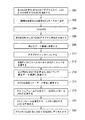
図3の流れ図は、図2に関連して上述したフレーム・データ構造が使用される本発明の一実施形態を実行するための方法を示している。0〜15という従来の範囲の外側のLSSにアクセスするようにストレージ・システム130を構成するために、システム管理者は、各ESCONアダプタごとに、最大256個の定義済みLSSのうちの最大16個のLSSを選択する(300)。また、管理者は、それぞれについてLSS番号(0〜15)も選択する。この構成情報が入力された後、その情報はCU132のオペレーティング・システムのカーネルに渡される(302)。CU132の初期マイクロコード・ロード(IML)操作が開始されると(304)、カーネルは、各ESCONアダプタに構成情報を送信し(306)、テーブルまたはアレイなどの構成データ構造にその構成を保管する(308)。図4は、2つの要素を有する例示的な構成データ構造400を示している。第1の要素は選択されたVLSS402を識別し、第2の要素はVLSSに割り当てられたポートまたはLSS番号404を識別する。したがって、図4のデータ構造では、CU132によりアクセス可能なものとして、VLSS番号1、4、15、72、123、および246が選択されている(明瞭にするため、他に可能な9つのVLSSはこのデータ構造には含まれていない)。このVLSSには、LSS番号0、1、2、3、14、および15がそれぞれ割り当てられている。
The flow diagram of FIG. 3 illustrates a method for implementing an embodiment of the present invention in which the frame data structure described above in connection with FIG. 2 is used. To configure the
その後、アダプタがオンラインになると(310)、ホスト・デバイス110は、それが確立しようとする各論理パスごとに従来の論理パス確立(Establish Logical Path:ELP)コマンドを送信する。ELP内には、LSS(0〜15)および論理パスのアドレスが含まれる。ELP処理中に、アダプタ・ファームウェア/マイクロコードは、LSSに対応するVLSSの識別を要求する照会をオペレーティング・システムに送信する(314)。次に、VLSS番号は、ホスト・チャネル・サブシステム112およびコントロール・ユニット132のリンク・アドレスとともに、テーブルまたはアレイなどの論理パス・データ構造に保管され、それにより、論理パスを完全に定義する(316)。例示的な論理パス・データ構造は図5に示されている。この論理パス・データ構造は、適切なホストにフレームを返送するために必要な情報(物理アドレスと論理アドレスの両方を必要とする)ならびにフレームが送信されたコントロール・ユニットの論理アドレスを提供する。CU仮想LSSは、操作が実際に処理されるコントロール・ユニット上のLSSへのマッピングである。
Thereafter, when the adapter goes online (310), the
ホスト・デバイス110にフレームを送信する場合、VLSSに対応するLSS番号が使用されることになる(318)。同様に、ホスト110からCU132にフレームを送信する場合、LSS番号が使用されることになり(320)、対応するVLSSについて論理パス・テーブルが照会されることになる。ここで本発明は、FICONなどの非ESCONネットワーク150(図1)によりすでにデータが書き込まれた可能性がある、前にアクセス不能だったLSSへのアクセスを可能にする。
When transmitting a frame to the
本明細書に記載した実施形態は特にESCON環境に向けられているが、本発明の原理は、FICONなど、他のデータ・ストレージ環境に適用することができる。FICONネットワークでは、最大28=256個のLSSをアドレッシングすることができる。しかし、ESCONに関して本明細書に記載したものと同様に、本発明では29=512個の仮想LSSへのアクセスを許可する。 Although the embodiments described herein are specifically directed to ESCON environments, the principles of the present invention can be applied to other data storage environments, such as FICON. In the FICON network, a maximum of 2 8 = 256 LSSs can be addressed. However, similar to what is described herein for ESCON, the present invention allows access to 2 9 = 512 virtual LSSs.
本発明の諸目的は、本明細書に開示した諸実施形態により完全に実現されている。当業者であれば、本発明の様々な態様が、本発明の本質的な機能を逸脱せずに、種々の実施形態によって達成可能であることが分かるであろう。特定の諸実施形態は例示的なものであり、特許請求の範囲に示す本発明の範囲を制限するためのものではない。 The objectives of the present invention are fully realized by the embodiments disclosed herein. Those skilled in the art will appreciate that various aspects of the present invention can be achieved by various embodiments without departing from the essential function of the present invention. The specific embodiments are illustrative and are not intended to limit the scope of the invention as set forth in the claims.
000:プロセッサ
100:データ処理システム
110:ホスト
112:チャネル・サブシステム
120:ストレージ・ネットワーク(ESCON)
130:ストレージ・システム
132:コントロール・ユニット
134:LSS0〜LSS255
136:CKDディスク
138:固定ブロック・ディスク
140:ストレージ・システム
142:コントロール・ユニット
144:LSS0〜LSS255
146:CKDディスク
148:固定ブロック・ディスク
150:非ESCON
000: processor 100: data processing system 110: host 112: channel subsystem 120: storage network (ESCON)
130: Storage system 132: Control unit 134: LSS0 to LSS255
136: CKD disk 138: Fixed block disk 140: Storage system 142: Control unit 144: LSS0 to LSS255
146: CKD disk 148: Fixed block disk 150: Non-ESCON
Claims (8)
(a)ホスト・デバイスに接続されたコントロール・ユニットと、
(b)複数の論理サブシステム(LSS)とを備え、
各LSSが前記コントロール・ユニットに割当て可能であり、xビットのLSS番号によって第1のネットワーク内でアドレス可能であり、各LSSがyビットの仮想LSS(VLSS)番号を有し(但し、xおよびyは1より大きい正の整数であり、かつy>xである)、
(c)前記ホスト・デバイスによって送信されるデータを格納するために各LSSに割当て可能な少なくとも1つのデータ・ストレージ・デバイスと、
(d)最大2 x 個のVLSSを前記コントロール・ユニットに割り当てるための手段と、
(e)割り当てられた各VLSSを対応するLSS番号によって識別するための、前記コントロール・ユニット内の構成データ構造とをさらに備え、
前記コントロール・ユニットが、
割り当てられたLSSを識別するLSS番号を保持し、かつ当該割り当てられたLSSと前記ホスト・デバイスとの間に論理パスを確立するための論理パス確立(ELP)コマンドを前記ホスト・デバイスから受信し、
前記ELPコマンドに保持されたLSS番号に対応するVLSS番号を前記構成データ構造から入手し、
前記構成データ構造から入手したVLSS番号を前記コントロール・ユニット内の論理パス・データ構造に保管して、当該VLSS番号を、前記ELPコマンドによって確立された論理パスの他のエレメントである、前記ホスト・デバイスおよび前記コントロール・ユニットのリンク・アドレスに関連付け、
前記ホスト・デバイスから、前記選択されたLSSのうち少なくとも1つのLSSを識別するLSS番号を保持し、かつ当該少なくとも1つのLSSにアクセスするための入出力操作用コマンドを受信し、
前記入出力操作用コマンドに保持されたLSS番号に対応するVLSS番号を前記論理パス・データ構造から入手し、かつ当該VLSS番号を有するLSSにアクセスするように構成される、データ・ストレージ・システム。 A data storage system,
(A) a control unit connected to the host device ;
(B) comprising a plurality of logical subsystems (LSS) ;
Each LSS is assignable to the control unit and is addressable in the first network by an x-bit LSS number, and each LSS has a y-bit virtual LSS (VLSS) number (where x and y is a positive integer greater than 1 and y> x ),
(C) at least one data storage device that can be assigned to each LSS for storing data that is sent by the previous Kiho strike device,
(D) means for allocating a maximum of 2 x VLSSs to the control unit;
(E) further comprising a configuration data structure in the control unit for identifying each assigned VLSS by a corresponding LSS number;
The control unit is
A logical path establishment (ELP) command is received from the host device to hold an LSS number identifying the assigned LSS and to establish a logical path between the assigned LSS and the host device. ,
Get V LSS number that corresponds to the LSS number held in the ELP command from said configuration data structure,
The VLSS number obtained from the configuration data structure is stored in a logical path data structure in the control unit, and the VLSS number is another element of the logical path established by the ELP command. associated with with the device and the control unit of the link address,
Before Symbol host device, hold the L SS number identifying at least one LSS of said selected LSS, and receives the input operation commands for accessing the at least one LSS,
Said VLSS number that corresponds to L SS number held in the input and output operations for the command obtained from the logical path data structures, and Ru is configured to access the L SS that have a corresponding V LSS number, Data storage system.
(a)最大2 y 個の論理サブシステム(LSS)を設けるステップを含み、
各LSSがyビットの仮想LSS(VLSS)番号を有し(但し、yは1より大きい正の整数である)、
(b)前記最大2 y 個のLSSから、ホスト・デバイスに接続されたコントロール・ユニットに割り当てるべき最大2 x 個のLSSを選択するステップを含み、
選択された各LSSがxビットのLSS番号によって第1のネットワーク内でアドレス可能であり(但し、xは1より大きい正の整数であり、かつx<yである)、
(c)選択された各LSSごとに、LSS番号を割り当てるステップと、
(d)選択された各LSSの前記割り当てられたLSS番号を、当該LSS番号に対応するように割り当てられたVLSS番号とともに、前記コントロール・ユニット内の構成データ構造に保管するステップと、
(e)前記コントロール・ユニットにおいて、前記ホスト・デバイスから、前記選択されたLSSのうち少なくとも1つのLSSを識別するLSS番号を保持し、かつ前記ホスト・デバイスと当該少なくとも1つのLSSとの間に論理パスを確立するための論理パス確立(ELP)コマンドを受信するステップと、
(f)前記ELPコマンドに保持されたLSS番号に対応するVLSS番号を前記構成データ構造から入手し、当該VLSS番号を、前記ELPコマンドによって確立された論理パスの他のエレメントである、前記ホスト・デバイスおよび前記コントロール・ユニットのリンク・アドレスとともに、前記コントロール・ユニット内の論理パス・データ構造に保管するステップと、
(g)前記コントロール・ユニットにおいて、前記ホスト・デバイスから、前記選択されたLSSのうち少なくとも1つのLSSを識別するLSS番号を保持し、かつ当該少なくとも1つのLSSにアクセスするための入出力操作用コマンドを受信するステップと、
(h)前記入出力操作用コマンドに保持されたLSS番号に対応するVLSS番号を前記論理パス・データ構造から入手し、かつ当該VLSS番号を有するLSSにアクセスするステップをさらに含む、方法。 A method for managing logical paths in a data storage system, comprising:
(A) comprises steps of providing a maximum 2 y-number of logical subsystem (LSS),
Each LSS has a y-bit virtual LSS (VLSS) number (where y is a positive integer greater than 1) ;
(B) from the maximum 2 y-number of LSS, contain up to 2 x number of steps that the L S S to select to be assigned to the control unit connected to a host device,
Each LSS that has been selected is addressable within the first network by LSS number of x bits (where, x is a positive integer greater than one, and is x <y),
(C) assigning an LSS number for each selected LSS;
(D) is selected the allocated LSS number for each LSS has, together with the LSS number corresponds to so that the assignment was VLSS number, and storing steps to configure data structure in the control unit ,
(E) The control unit holds an LSS number identifying at least one LSS among the selected LSSs from the host device, and between the host device and the at least one LSS. Receiving a logical path establishment (ELP) command to establish a logical path ;
The V LSS number corresponding to the LSS number held in the (f) the ELP command obtained from the configuration data structure, said VLSS number, which is another element of the logical path established by the ELP command before Symbol with host device and the control unit of the link address, and storing steps to logical path data structure in the control unit,
(G) in the control unit, before Symbol host device, hold the L SS number identifying at least one LSS of said selected LSS, and input for accessing the at least one LSS Receiving an output operation command; and
(H) said VLSS number that corresponds to the held L SS number to the input-output operation command obtained from the logical path data structures, and further the step of accessing the L SS that have a corresponding V LSS number Including .
Applications Claiming Priority (2)
| Application Number | Priority Date | Filing Date | Title |
|---|---|---|---|
| US10/874,160 | 2004-06-22 | ||
| US10/874,160 US7574529B2 (en) | 2004-06-22 | 2004-06-22 | Addressing logical subsystems in a data storage system |
Publications (3)
| Publication Number | Publication Date |
|---|---|
| JP2006012169A JP2006012169A (en) | 2006-01-12 |
| JP2006012169A5 JP2006012169A5 (en) | 2008-06-19 |
| JP4738069B2 true JP4738069B2 (en) | 2011-08-03 |
Family
ID=35481876
Family Applications (1)
| Application Number | Title | Priority Date | Filing Date |
|---|---|---|---|
| JP2005181531A Expired - Fee Related JP4738069B2 (en) | 2004-06-22 | 2005-06-22 | Data storage system and method for managing logical paths in a data storage system |
Country Status (3)
| Country | Link |
|---|---|
| US (1) | US7574529B2 (en) |
| JP (1) | JP4738069B2 (en) |
| CN (1) | CN100365600C (en) |
Families Citing this family (7)
| Publication number | Priority date | Publication date | Assignee | Title |
|---|---|---|---|---|
| GB0613239D0 (en) * | 2006-07-04 | 2006-08-09 | Ibm | Storage area network system |
| JP5045229B2 (en) * | 2007-05-14 | 2012-10-10 | 富士ゼロックス株式会社 | Storage system and storage device |
| US8909827B2 (en) * | 2008-01-30 | 2014-12-09 | International Business Machines Corporation | Method to allow a host to replace logical path resources it owns |
| US8392610B2 (en) * | 2008-01-30 | 2013-03-05 | International Business Machines Corporation | Method, apparatus and system to dynamically manage logical path resources |
| JP2010205208A (en) * | 2009-03-06 | 2010-09-16 | Nec Corp | Host computer, multipath system, and method and program for allocating path |
| KR101466592B1 (en) * | 2010-06-18 | 2014-12-01 | 엘에스아이 코포레이션 | Scalable storage devices |
| US9921770B1 (en) * | 2014-03-28 | 2018-03-20 | EMC IP Holding Company LLC | Extending fixed block architecture device access over ficon using transport mode protocol |
Citations (3)
| Publication number | Priority date | Publication date | Assignee | Title |
|---|---|---|---|---|
| JP2001034568A (en) * | 1999-07-21 | 2001-02-09 | Fujitsu Ltd | Logical path establishing method, and storage medium |
| JP2001265655A (en) * | 2000-01-14 | 2001-09-28 | Hitachi Ltd | Security system for storage sub system |
| US20030088638A1 (en) * | 2001-11-06 | 2003-05-08 | International Business Machines Corporation | Support of fixed-block storage devices over escon links |
Family Cites Families (4)
| Publication number | Priority date | Publication date | Assignee | Title |
|---|---|---|---|---|
| JP2566728B2 (en) | 1992-10-30 | 1996-12-25 | インターナショナル・ビジネス・マシーンズ・コーポレイション | Logical path scheduling device and execution method |
| US5555371A (en) | 1992-12-17 | 1996-09-10 | International Business Machines Corporation | Data backup copying with delayed directory updating and reduced numbers of DASD accesses at a back up site using a log structured array data storage |
| EP1484685A4 (en) * | 2002-03-07 | 2008-04-02 | Fujitsu Ltd | Storage virtualization system conversion management apparatus and storage virtualization system conversion management method |
| US7010663B2 (en) * | 2002-03-22 | 2006-03-07 | Sun Microsystems, Inc. | Method and system for dividing a plurality of existing volumes of storage into a plurality of virtual logical units of storage |
-
2004
- 2004-06-22 US US10/874,160 patent/US7574529B2/en not_active Expired - Fee Related
-
2005
- 2005-04-15 CN CNB2005100657673A patent/CN100365600C/en not_active Expired - Fee Related
- 2005-06-22 JP JP2005181531A patent/JP4738069B2/en not_active Expired - Fee Related
Patent Citations (3)
| Publication number | Priority date | Publication date | Assignee | Title |
|---|---|---|---|---|
| JP2001034568A (en) * | 1999-07-21 | 2001-02-09 | Fujitsu Ltd | Logical path establishing method, and storage medium |
| JP2001265655A (en) * | 2000-01-14 | 2001-09-28 | Hitachi Ltd | Security system for storage sub system |
| US20030088638A1 (en) * | 2001-11-06 | 2003-05-08 | International Business Machines Corporation | Support of fixed-block storage devices over escon links |
Also Published As
| Publication number | Publication date |
|---|---|
| CN1713161A (en) | 2005-12-28 |
| JP2006012169A (en) | 2006-01-12 |
| CN100365600C (en) | 2008-01-30 |
| US7574529B2 (en) | 2009-08-11 |
| US20050283538A1 (en) | 2005-12-22 |
Similar Documents
| Publication | Publication Date | Title |
|---|---|---|
| US6073209A (en) | Data storage controller providing multiple hosts with access to multiple storage subsystems | |
| US9037816B1 (en) | Reversing a communication path between storage devices | |
| US7409470B2 (en) | Determining configuration data in connection with dynamic RDF | |
| US7945748B2 (en) | Data migration and copying in a storage system with dynamically expansible volumes | |
| JP4738069B2 (en) | Data storage system and method for managing logical paths in a data storage system | |
| US7069393B2 (en) | Storage system providing file aware caching and file aware remote copy | |
| CN101799743B (en) | Method and apparatus for logical volume management | |
| US20060236054A1 (en) | Highly available external storage system | |
| US7143176B2 (en) | Data communication with a protocol that supports a given logical address range | |
| JP2006024215A (en) | Method and apparatus for connecting multi-layered external storage device and disk array based input and output routine | |
| JP2006500693A (en) | Dynamic RDF group | |
| JP2003263352A (en) | Remote data facility on ip network | |
| US6105076A (en) | Method, system, and program for performing data transfer operations on user data | |
| US20100011179A1 (en) | Remote copy system and method | |
| US6282584B1 (en) | Structure and method for reading/writing signature commands from/to a plurality of controller pairs | |
| US6810447B2 (en) | Hierarchical approach to identifying changing device characteristics | |
| JP2003044421A (en) | Virtual storage system and switching node used for the same system | |
| JP5272185B2 (en) | Computer system and storage system | |
| JP4433372B2 (en) | Data access system and method | |
| US11262952B2 (en) | Concurrent tape modification | |
| US7260612B2 (en) | Switching system duplicating file operation command according to quantity of file servers and sending writing and reading commands according to a switching order | |
| US10216652B1 (en) | Split target data transfer | |
| US10318171B1 (en) | Accessing fast memory in a data storage array | |
| US11546274B2 (en) | Encapsulated FICON communication | |
| US11669356B2 (en) | Simulation for alternative communication |
Legal Events
| Date | Code | Title | Description |
|---|---|---|---|
| A521 | Request for written amendment filed |
Free format text: JAPANESE INTERMEDIATE CODE: A523 Effective date: 20080428 |
|
| A621 | Written request for application examination |
Free format text: JAPANESE INTERMEDIATE CODE: A621 Effective date: 20080428 |
|
| RD03 | Notification of appointment of power of attorney |
Free format text: JAPANESE INTERMEDIATE CODE: A7423 Effective date: 20090206 |
|
| A977 | Report on retrieval |
Free format text: JAPANESE INTERMEDIATE CODE: A971007 Effective date: 20101228 |
|
| A131 | Notification of reasons for refusal |
Free format text: JAPANESE INTERMEDIATE CODE: A131 Effective date: 20110118 |
|
| A521 | Request for written amendment filed |
Free format text: JAPANESE INTERMEDIATE CODE: A523 Effective date: 20110315 |
|
| A01 | Written decision to grant a patent or to grant a registration (utility model) |
Free format text: JAPANESE INTERMEDIATE CODE: A01 Effective date: 20110419 |
|
| A01 | Written decision to grant a patent or to grant a registration (utility model) |
Free format text: JAPANESE INTERMEDIATE CODE: A01 |
|
| A61 | First payment of annual fees (during grant procedure) |
Free format text: JAPANESE INTERMEDIATE CODE: A61 Effective date: 20110426 |
|
| R150 | Certificate of patent or registration of utility model |
Free format text: JAPANESE INTERMEDIATE CODE: R150 |
|
| FPAY | Renewal fee payment (event date is renewal date of database) |
Free format text: PAYMENT UNTIL: 20140513 Year of fee payment: 3 |
|
| LAPS | Cancellation because of no payment of annual fees |