JP4732948B2 - Transmitting apparatus, receiving apparatus, and random access control method - Google Patents
Transmitting apparatus, receiving apparatus, and random access control method Download PDFInfo
- Publication number
- JP4732948B2 JP4732948B2 JP2006127994A JP2006127994A JP4732948B2 JP 4732948 B2 JP4732948 B2 JP 4732948B2 JP 2006127994 A JP2006127994 A JP 2006127994A JP 2006127994 A JP2006127994 A JP 2006127994A JP 4732948 B2 JP4732948 B2 JP 4732948B2
- Authority
- JP
- Japan
- Prior art keywords
- random access
- access channel
- signature
- control information
- preamble part
- Prior art date
- Legal status (The legal status is an assumption and is not a legal conclusion. Google has not performed a legal analysis and makes no representation as to the accuracy of the status listed.)
- Active
Links
- 238000000034 method Methods 0.000 title claims description 22
- 230000005540 biological transmission Effects 0.000 claims description 45
- 238000001514 detection method Methods 0.000 claims description 37
- 108010003272 Hyaluronate lyase Proteins 0.000 description 23
- 238000004891 communication Methods 0.000 description 7
- 230000008569 process Effects 0.000 description 4
- 238000013468 resource allocation Methods 0.000 description 4
- 230000007480 spreading Effects 0.000 description 4
- 244000126211 Hericium coralloides Species 0.000 description 2
- 230000008859 change Effects 0.000 description 2
- 238000006243 chemical reaction Methods 0.000 description 2
- 125000004122 cyclic group Chemical group 0.000 description 2
- 230000007423 decrease Effects 0.000 description 2
- 238000010586 diagram Methods 0.000 description 2
- 238000005259 measurement Methods 0.000 description 2
- 230000004044 response Effects 0.000 description 2
- 230000007704 transition Effects 0.000 description 2
- 230000006978 adaptation Effects 0.000 description 1
- 238000010295 mobile communication Methods 0.000 description 1
- 235000002020 sage Nutrition 0.000 description 1
Images


Classifications
-
- H—ELECTRICITY
- H04—ELECTRIC COMMUNICATION TECHNIQUE
- H04W—WIRELESS COMMUNICATION NETWORKS
- H04W74/00—Wireless channel access, e.g. scheduled or random access
- H04W74/08—Non-scheduled or contention based access, e.g. random access, ALOHA, CSMA [Carrier Sense Multiple Access]
-
- H—ELECTRICITY
- H04—ELECTRIC COMMUNICATION TECHNIQUE
- H04J—MULTIPLEX COMMUNICATION
- H04J13/00—Code division multiplex systems
-
- H—ELECTRICITY
- H04—ELECTRIC COMMUNICATION TECHNIQUE
- H04L—TRANSMISSION OF DIGITAL INFORMATION, e.g. TELEGRAPHIC COMMUNICATION
- H04L1/00—Arrangements for detecting or preventing errors in the information received
- H04L1/0001—Systems modifying transmission characteristics according to link quality, e.g. power backoff
- H04L1/0023—Systems modifying transmission characteristics according to link quality, e.g. power backoff characterised by the signalling
- H04L1/0026—Transmission of channel quality indication
-
- H—ELECTRICITY
- H04—ELECTRIC COMMUNICATION TECHNIQUE
- H04L—TRANSMISSION OF DIGITAL INFORMATION, e.g. TELEGRAPHIC COMMUNICATION
- H04L1/00—Arrangements for detecting or preventing errors in the information received
- H04L1/004—Arrangements for detecting or preventing errors in the information received by using forward error control
- H04L1/0072—Error control for data other than payload data, e.g. control data
-
- H—ELECTRICITY
- H04—ELECTRIC COMMUNICATION TECHNIQUE
- H04L—TRANSMISSION OF DIGITAL INFORMATION, e.g. TELEGRAPHIC COMMUNICATION
- H04L1/00—Arrangements for detecting or preventing errors in the information received
- H04L1/0078—Avoidance of errors by organising the transmitted data in a format specifically designed to deal with errors, e.g. location
- H04L1/0079—Formats for control data
-
- H—ELECTRICITY
- H04—ELECTRIC COMMUNICATION TECHNIQUE
- H04W—WIRELESS COMMUNICATION NETWORKS
- H04W72/00—Local resource management
- H04W72/04—Wireless resource allocation
- H04W72/044—Wireless resource allocation based on the type of the allocated resource
- H04W72/0453—Resources in frequency domain, e.g. a carrier in FDMA
-
- H—ELECTRICITY
- H04—ELECTRIC COMMUNICATION TECHNIQUE
- H04J—MULTIPLEX COMMUNICATION
- H04J13/00—Code division multiplex systems
- H04J13/16—Code allocation
-
- H—ELECTRICITY
- H04—ELECTRIC COMMUNICATION TECHNIQUE
- H04L—TRANSMISSION OF DIGITAL INFORMATION, e.g. TELEGRAPHIC COMMUNICATION
- H04L1/00—Arrangements for detecting or preventing errors in the information received
- H04L1/004—Arrangements for detecting or preventing errors in the information received by using forward error control
- H04L1/0056—Systems characterized by the type of code used
- H04L1/0057—Block codes
-
- H—ELECTRICITY
- H04—ELECTRIC COMMUNICATION TECHNIQUE
- H04L—TRANSMISSION OF DIGITAL INFORMATION, e.g. TELEGRAPHIC COMMUNICATION
- H04L5/00—Arrangements affording multiple use of the transmission path
- H04L5/0001—Arrangements for dividing the transmission path
- H04L5/0003—Two-dimensional division
- H04L5/0005—Time-frequency
- H04L5/0007—Time-frequency the frequencies being orthogonal, e.g. OFDM(A), DMT
-
- H—ELECTRICITY
- H04—ELECTRIC COMMUNICATION TECHNIQUE
- H04L—TRANSMISSION OF DIGITAL INFORMATION, e.g. TELEGRAPHIC COMMUNICATION
- H04L5/00—Arrangements affording multiple use of the transmission path
- H04L5/003—Arrangements for allocating sub-channels of the transmission path
- H04L5/0053—Allocation of signaling, i.e. of overhead other than pilot signals
-
- H—ELECTRICITY
- H04—ELECTRIC COMMUNICATION TECHNIQUE
- H04W—WIRELESS COMMUNICATION NETWORKS
- H04W74/00—Wireless channel access, e.g. scheduled or random access
- H04W74/08—Non-scheduled or contention based access, e.g. random access, ALOHA, CSMA [Carrier Sense Multiple Access]
- H04W74/0833—Non-scheduled or contention based access, e.g. random access, ALOHA, CSMA [Carrier Sense Multiple Access] using a random access procedure
Description
本発明は、送信装置および受信装置並びにランダムアクセス制御方法に関する。 The present invention relates to a transmission device, a reception device, and a random access control method.
W−CDMAやHSDPAの後継として、Evolved UTRA(E−UTRA)と呼ばれる通信方式が検討されている。E−UTRAは、複数の帯域幅を拡張可能にサポートする無線アクセス方式であり、既存の3G方式との親和性を確保しつつ、1.25MHzから最大20MHzまでの帯域幅に対応するものである。 As a successor to W-CDMA and HSDPA, a communication method called Evolved UTRA (E-UTRA) has been studied. E-UTRA is a wireless access system that supports a plurality of bandwidths in an expandable manner, and supports a bandwidth from 1.25 MHz to a maximum of 20 MHz while ensuring compatibility with existing 3G systems. .
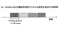
既存のW−CDMAでは、同一システム内において、衝突許容チャネルの1つであり、上りリンクにおける初期接続の確立に用いられるランダムアクセスチャネル用プリアンブルは、コード多重、時間多重の組み合わせにより送信されていた。 In the existing W-CDMA, one of the collision permissible channels in the same system, the preamble for the random access channel used for establishing the initial connection in the uplink was transmitted by a combination of code multiplexing and time multiplexing. .
例えば、図1Aに示すように、コード多重によりユーザが多重される場合には、端末は、複数用意されたシグネチャ(コード)の中から任意のシグネチャを選択できる。 For example, as shown in FIG. 1A, when users are multiplexed by code multiplexing, the terminal can select an arbitrary signature from a plurality of prepared signatures (codes).
また、例えば、図1Bに示すように、時間多重によりユーザが多重される場合には、端末は、複数用意されたアクセススロットの中から任意のアクセススロットを選択できる。 For example, as shown in FIG. 1B, when users are multiplexed by time multiplexing, the terminal can select an arbitrary access slot from among a plurality of prepared access slots.
なお、W−CDMAのランダムアクセスについては、非特許文献1に記載されている。
これに対し、E−UTRAに対応するシステムでは、同一システム内に複数の帯域幅が定義されており、基地局あるいは事業者によって異なる帯域幅がサポートされる。すなわち各事業者が展開するシステム(場合によっては同一事業者のシステム内のセル)によって使用する帯域幅が異なるという状態が生じる。このような状況で、全ての移動端末が、異なる帯域幅の任意の基地局に接続する必要がある。 On the other hand, in a system corresponding to E-UTRA, a plurality of bandwidths are defined in the same system, and different bandwidths are supported by base stations or operators. That is, a state occurs in which the bandwidth used varies depending on the system (in some cases, a cell in the system of the same provider) deployed by each provider. In such a situation, all mobile terminals need to connect to arbitrary base stations with different bandwidths.
また、E−UTRAに対応するシステムでは、上りリンクの無線アクセス方式として、シングルキャリアLocalized/Distributed FDMA無線アクセス方式が検討されている。 Further, in a system corresponding to E-UTRA, a single carrier localized / distributed FDMA radio access scheme has been studied as an uplink radio access scheme.
一般に、プリアンブル部は、セル端等からでも、RACHが送られてきたことを検出するために、かなり長い系列が必要とされる。例えば、W−CDMAでは、1msec長(4096chips)である。 In general, the preamble part requires a fairly long sequence in order to detect that the RACH has been sent even from the cell edge or the like. For example, in W-CDMA, it is 1 msec long (4096 chips).
一方、制御情報も、セル端からも受信できるようにするとかなり大きな拡散率が必要になる。例えば、プリアンブルに比べれば小さいがSF=64程度が必要になる。 On the other hand, if control information can be received from the cell edge, a considerably large spreading factor is required. For example, although SF is smaller than the preamble, SF = 64 is required.
したがって、制御情報を全てプリアンブル部と別に送ると、RACHの系列長が非常に長くなって効率が悪くなる。または、送ることができる制御ビット数が少なくなる。 Therefore, if all the control information is sent separately from the preamble part, the RACH sequence length becomes very long and the efficiency becomes poor. Alternatively, the number of control bits that can be transmitted is reduced.
そこで、本発明は、上述した問題のうち少なくとも1つを解決するためになされたものであり、プリアンブル部で制御情報の少なくとも一部を送信することができる送信装置および受信装置並びにランダムアクセス制御方法を提供することにある。 Accordingly, the present invention has been made to solve at least one of the above-described problems, and a transmission device, a reception device, and a random access control method capable of transmitting at least a part of control information in a preamble section. Is to provide.
上記課題を解決するため、本発明の送信装置は、
衝突許容型チャネルに割り当てられた周波数帯域の中で、
少なくとも制御情報の一部を含むプリアンブル部から構成されるランダムアクセスチャネルを生成するランダムアクセスチャネル生成手段;
各ユーザに対して、連続的な周波数割り当ておよび非連続的なくしの歯状の周波数割り当てのうちの一方を行う割り当てを行い、前記ランダムアクセスチャネルを可変のマルチ帯域幅で送信する送信制御手段;
を備えることを特徴の1つとする。
In order to solve the above problems, the transmission device of the present invention provides:
Among the frequency bands allocated to collision-acceptable channels,
Random access channel generating means for generating a random access channel configured by a preamble part including at least part of control information;
Transmission control means for assigning each user one of continuous frequency assignment and non-continuous comb-like frequency assignment, and transmitting the random access channel with a variable multi-bandwidth;
It is one of the features to provide.
このように構成することにより、プリアンブル部を用いて、制御情報を送信することができる。 With this configuration, it is possible to transmit control information using the preamble part.
また、本発明の受信装置は、
1または複数の移動局からランダムアクセスチャネルを受信する受信手段;
前記ランダムアクセスチャネルからプリアンブル部および制御メッセージ部の検出を行う検出処理手段;
を備え、
前記検出処理手段は、前記プリアンブル部が複数のブロックに分割され、各ブロックにおいて制御情報を示すシンボル系列にシグネチャ系列が乗算されている場合、各ブロックのシグネチャを検出し、制御情報を示すシンボル系列を検出することを特徴の1つとする。
The receiving device of the present invention is
Receiving means for receiving a random access channel from one or more mobile stations;
Detection processing means for detecting a preamble part and a control message part from the random access channel;
With
The detection processing means detects the signature of each block when the preamble part is divided into a plurality of blocks and a symbol sequence indicating control information is multiplied in each block, and a symbol sequence indicating control information Is one of the features.
このように構成することにより、プリアンブル部を用いて送信された制御情報を受信することができる。 With this configuration, it is possible to receive control information transmitted using the preamble part.
また、本発明のランダムアクセス制御方法は、
衝突許容型チャネルに割り当てられた周波数帯域の中で、
少なくとも制御情報の一部を含むプリアンブル部から構成されるランダムアクセスチャネルを生成するランダムアクセスチャネル生成ステップ;
各ユーザに対して、連続的な周波数割り当ておよび非連続的なくしの歯状の周波数割り当てのうちの一方を行う割り当てステップ;
前記ランダムアクセスチャネルを可変のマルチ帯域幅で送信する送信ステップ;
を有することを特徴の1つとする。
The random access control method of the present invention is
Among the frequency bands allocated to collision-acceptable channels,
A random access channel generation step of generating a random access channel including a preamble part including at least a part of control information;
An assigning step for each user, one of continuous frequency assignment and non-continuous comb-like frequency assignment;
Transmitting the random access channel with variable multi-bandwidth;
One of the features is to have
このように構成することにより、プリアンブル部を用いて、制御情報を送信することができる。 With this configuration, it is possible to transmit control information using the preamble part.
本発明の実施例によれば、プリアンブル部で制御情報の少なくとも一部を送信することができる送信装置および受信装置並びにランダムアクセス制御方法を実現できる。 According to the embodiment of the present invention, it is possible to realize a transmission device, a reception device, and a random access control method that can transmit at least a part of control information in the preamble section.
次に、本発明を実施するための最良の形態を、以下の実施例に基づき図面を参照しつつ説明する。
なお、実施例を説明するための全図において、同一機能を有するものは同一符号を用い、繰り返しの説明は省略する。
Next, the best mode for carrying out the present invention will be described based on the following embodiments with reference to the drawings.
In all the drawings for explaining the embodiments, the same reference numerals are used for those having the same function, and repeated explanation is omitted.
本発明の実施例にかかる無線通信システムは、移動局と基地局とを備える。 A wireless communication system according to an embodiment of the present invention includes a mobile station and a base station.
本実施例にかかる無線通信システムには、上りリンクシングルキャリアLocalized/Distributed FDMA無線アクセス方式が適用される。移動局は、ランダムアクセスを行う際に、ランダムアクセスチャネルを送信する。 An uplink single carrier localized / distributed FDMA radio access scheme is applied to the radio communication system according to the present embodiment. The mobile station transmits a random access channel when performing random access.
次に、本発明の実施例にかかる送信装置100について、図2を参照して説明する。
Next, the
本実施例にかかる送信装置100は、例えば移動局に備えられ、上りリンクシングルキャリアLocalized/Distributed FDMA無線アクセスにおいて、ランダムアクセスを行う際に、ランダムアクセスチャネルを用いる。このランダムアクセスチャネルでは、プリアンブルと、制御情報の少なくとも一部が一緒に送信される。
The
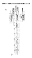
送信装置100は、送信データが入力されるD/Aコンバータ102と、D/Aコンバータ102の出力信号が入力されるIFフィルタ104と、IFフィルタ104の出力信号が入力されるアップコンバータ106と、アップコンバータ106の出力信号が入力されるRFフィルタ108と、RFフィルタ108の出力信号が入力される送信電力増幅器(Power Amplifier: PA)110と、ランダムアクセスチャネル生成手段としての衝突許容チャネル生成部112と、衝突許容チャネル生成部112の出力信号が入力される乗算部114と、乗算部114の出力信号が入力される帯域制限フィルタ116と、衝突許容チャネル生成部112と帯域制限フィルタ116とPA110とを制御する送信制御手段としての制御部120と、乗算部114にランダムアクセスチャネルに用いる拡散率を変更する拡散率制御部118とを備える。
The
ベースバンド処理されたランダムアクセスチャネルは、IF部のD/Aコンバータ102に入力され、IFフィルタ104を通過する。IFフィルタ104の出力は、RF部のアップコンバータ106に入力され、設定された上りリンク送信周波数帯に応じたRF周波数に変換される。なお、この機能の一部はベースバンド部で行なってもよい。RF変換された信号は、RFフィルタ108を通過する。
The baseband processed random access channel is input to the D /
RFフィルタ108の出力はPA110で増幅される。一般には、下りリンクのパイロットチャネルの受信電力に基づいて、ランダムアクセスチャネルの送信電力を決定するオープンループ型の送信電力制御が行われる。増幅された送信信号は、送信アンテナから送信される。
The output of the
衝突許容チャネル生成部112は、衝突許容チャネル、例えばランダムアクセスチャネル(RACH)を生成し、乗算部114に入力する。
The collision allowable
ここで、ランダムアクセスチャネルで送信される情報について、説明する。 Here, information transmitted through the random access channel will be described.
本実施例にかかる送信装置100では、シグネチャ、およびユーザID、下りリンクチャネル状態を示す情報、スケジューリング要求情報、目的識別子およびCRC(Cyclic Redundancy Check)のうちの少なくとも一部が、ランダムアクセスチャネルにより送信される。
In the
シグネチャは、複数ユーザのランダムアクセスを識別するための情報であり、プリアンブル部で送信される。基地局では、シグネチャを用いてタイミング同期が行われる。W−CDMAの場合、このシグネチャは16種類である。 The signature is information for identifying random access of a plurality of users, and is transmitted in the preamble part. In the base station, timing synchronization is performed using the signature. In the case of W-CDMA, there are 16 types of signatures.
ユーザIDは、ランダム仮ID(Random temporary ID)またはUE IDから構成される。ランダム仮IDは、接続セルからUE IDを付与される前、例えばアイドル(IDLE)状態で使用される。移動局は、UE IDを接続セルから付与された後、ランダムアクセスチャネルを送信する場合に、該ランダムアクセスチャネルにUE IDをつけて送信する。ユーザIDには、例えば10bit−14bit程度必要とされる。 The user ID includes a random temporary ID (UE) or a UE ID. The random temporary ID is used, for example, in an idle (IDLE) state before being given a UE ID from the connected cell. When a mobile station transmits a random access channel after giving a UE ID from the connected cell, the mobile station transmits the random access channel with the UE ID. For example, about 10 to 14 bits are required for the user ID.
下りリンクチャネル状態(CQI)は、ランダムアクセスに対する下りリンクのフィードバックチャネルのリンクアダプテーション、例えば送信電力制御、AMCなどと、最初のスケジューリングにおけるCQI値として使用される。下りリンクチャネル状態には、例えば2bit−8bit程度必要とされる。 The downlink channel state (CQI) is used as the link adaptation of the downlink feedback channel for random access, for example, transmission power control, AMC, and the CQI value in the initial scheduling. In the downlink channel state, for example, about 2 bits to 8 bits are required.
スケジューリング要求情報は、スケジューリングの要求情報、例えば上りリンク・下りリンクの種別、データ量、所要誤り率・遅延時間などのQoSである。スケジューリング要求情報には、例えば1bit−8bit程度必要とされる。 The scheduling request information is scheduling request information, for example, QoS such as uplink / downlink type, data amount, required error rate / delay time, and the like. For example, about 1 to 8 bits are required for the scheduling request information.
目的指示子は、例えば、IDLE状態のランダムアクセスか、ACTIVE状態のランダムアクセスかを識別するための情報である。目的識別子は、例えば1bit−2bit程度必要とされる。 The purpose indicator is information for identifying, for example, random access in the IDLE state or random access in the ACTIVE state. The purpose identifier is required, for example, about 1 bit-2 bits.
CRCは、ランダムアクセスの制御情報の誤り検出のために使用される情報である。CRCは、例えば12bit程度必要とされる。 CRC is information used for error detection of random access control information. For example, CRC is required about 12 bits.
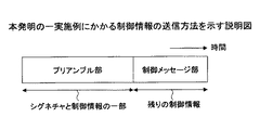
本実施例にかかる送信装置100が送信するランダムアクセスチャネルは、図3Aに示すように、プリアンブル部と制御メッセージ部とからなる。プリアンブル部ではシグネチャと制御情報の一部が送信され、制御メッセージ部ではプリアンブル部で送信される制御情報以外の残りの制御情報が送信される。
As shown in FIG. 3A, the random access channel transmitted by the transmitting
このランダムアクセスの構成において、プリアンブル部と制御メッセージ部は時間的に連続して1バーストとして送信される。 In this random access configuration, the preamble part and the control message part are transmitted as one burst continuously in time.
このように、プリアンブル部と制御メッセージ部とを時間的に連続して、言い換えればプリアンブル部に制御メッセージ部を付加して送信することにより、上りリンクのリンク確立に必要な遅延時間を低減できる。その結果、ランダムアクセスチャネルに後続する共有データチャネル(Shared data channel)における、トラヒックデータの送信に必要な遅延時間も低減できる。 In this way, by transmitting the preamble part and the control message part continuously in time, in other words, by adding the control message part to the preamble part and transmitting it, the delay time required for uplink link establishment can be reduced. As a result, the delay time required for transmission of traffic data in the shared data channel (Shared data channel) following the random access channel can also be reduced.
また、図3Bに示すように、プリアンブル部でシグネチャを送信し、制御メッセージ部で全制御情報を送信するようにしてもよい。このランダムアクセスの構成において、プリアンブル部と制御メッセージ部は時間的に連続して1バーストとして送信される。 Further, as shown in FIG. 3B, the signature may be transmitted by the preamble part, and all control information may be transmitted by the control message part. In this random access configuration, the preamble part and the control message part are transmitted as one burst continuously in time.
また、図3Cに示すように、プリアンブル部でシグネチャと全制御情報を送信するようにしてもよい。このようにすることにより、制御メッセージ部を無くすことができる。 Further, as shown in FIG. 3C, the signature and all control information may be transmitted in the preamble part. By doing in this way, a control message part can be eliminated.
ランダムアクセスチャネルにおけるプリアンブル部は、上りリンクのリンクを最初に確立するために用いられ、複数のランダムアクセスチャネルを識別・検出するためのシグネチャを含む。 The preamble part in the random access channel is used to initially establish an uplink link, and includes a signature for identifying and detecting a plurality of random access channels.
プリアンブル部により、受信装置(基地局)は、上りリンクの送信タイミング制御を行うための受信タイミング測定、マルチ帯域幅のシステムにおけるキャリア周波数の同定を行う。また、プリアンブル部は、制御メッセージ部の復調を行うためのチャネル推定を行うための参照シンボルの役割を有する。 With the preamble unit, the receiving apparatus (base station) performs reception timing measurement for performing uplink transmission timing control, and identifies a carrier frequency in a multi-bandwidth system. Also, the preamble part serves as a reference symbol for performing channel estimation for demodulating the control message part.
異なる上りリンクのユーザ間の信号が、普通は基地局と移動局の位置により、複数の移動局が同時に電波を送信しても、基地局で受信される場合にはそれらの受信信号のタイミングはずれてしまう。しかし、シングルキャリアLocalized/Distributed FDMAでは、Cyclic Prefix以内の受信タイミング誤差で受信されるように送信タイミング制御を行う。このようにすることにより、同一サブフレーム内のユーザ間の信号の周波数領域での直交性が実現される。 When signals between users on different uplinks are received at the base station, even if multiple mobile stations transmit radio waves simultaneously, depending on the position of the base station and the mobile station, the timing of these received signals may be shifted. End up. However, in single carrier localized / distributed FDMA, transmission timing control is performed so that reception is performed with a reception timing error within Cyclic Prefix. By doing so, orthogonality in the frequency domain of signals between users in the same subframe is realized.
また、パケットスケジューリングを行って時間領域での直交した無線リソースの割り当てを行うためにも、送信タイミング制御が必要である。 Also, transmission timing control is necessary to perform packet scheduling and assign orthogonal radio resources in the time domain.
そこで、上りリンクで最初に送信されるランダムアクセスチャネルを利用して、基地局は、受信タイミング測定を行うことにより、送信タイミング制御を行う。 Therefore, the base station performs transmission timing control by performing reception timing measurement using a random access channel transmitted first in the uplink.
また、マルチ帯域幅のシステムにおいて、移動局は、複数用意された周波数帯域の中から任意の周波数帯域を選択してランダムアクセスをすることができる。その際に、移動局が選択したキャリア周波数の同定を行う。例えば、各移動局はランダムに周波数帯域を選択する。 Further, in a multi-bandwidth system, a mobile station can perform random access by selecting an arbitrary frequency band from a plurality of prepared frequency bands. At that time, the carrier frequency selected by the mobile station is identified. For example, each mobile station selects a frequency band at random.
ランダムアクセスチャネルにおける制御情報には、上述したようにリンクを確立するための制御情報、後続する共有データチャネルにおいてデータを送信するために必要な予約情報が格納される。本実施例にかかる送信装置100は、ランダムアクセスチャネルにより、上りリンクのリンク確立のための必要最小限の情報を送信し、後続する共有データチャネルにより、トラヒックデータおよび上位レイヤの制御情報を送信する。
The control information in the random access channel stores control information for establishing a link as described above and reservation information necessary for transmitting data in the subsequent shared data channel. The
リンクを確立するための制御情報には、ユーザID、例えば移動局におけるランダムアクセス用のテンポラリのユーザID(ランダム仮ID)が含まれる。共有データチャネルにおいてデータを送信するために必要な予約情報には、データサイズ、データのQoS、例えば所要誤り率、許容遅延、特殊な呼(緊急呼)であることを示す情報など、移動局の能力(UE capability)、例えば送信可能な帯域幅、送信可能な最大送信電力、送信アンテナ数を示す情報が含まれる。 The control information for establishing the link includes a user ID, for example, a temporary user ID (random temporary ID) for random access in the mobile station. Reservation information required to transmit data on the shared data channel includes data size, data QoS, eg required error rate, allowable delay, information indicating special call (emergency call), etc. Information indicating a capability (UE capability), for example, a bandwidth that can be transmitted, a maximum transmission power that can be transmitted, and the number of transmission antennas is included.
乗算部114は、拡散率制御部118において決定された拡散符号で広帯域の信号に拡散し、帯域制限フィルタ116に入力する。
拡散制御部118は入力された受信状態を示す情報、すなわち移動局の平均的な受信状態に応じて、ランダムアクセスチャネルに用いる拡散率を変更する。 The spreading control unit 118 changes the spreading factor used for the random access channel according to the input information indicating the receiving state, that is, the average receiving state of the mobile station.
拡散率制御部118は、ランダムアクセスチャネルに対して予め定義された複数の拡散率の中から、受信状態に基づいて、拡散率を選択する。例えば、拡散率制御部118は、受信状態が悪い場合には大きな拡散率を選択し、受信状態が良い場合には小さな拡散率を選択する。すなわち、拡散率制御部118は可変拡散率制御を行う。拡散率制御部118は、プリアンブル部、制御メッセージ部の少なくとも一方について、拡散率の制御を行う。 The spreading factor control unit 118 selects a spreading factor based on the reception state from among a plurality of spreading factors previously defined for the random access channel. For example, the spreading factor control unit 118 selects a large spreading factor when the reception state is poor, and selects a small spreading factor when the reception state is good. That is, the spreading factor control unit 118 performs variable spreading factor control. The spreading factor control unit 118 controls spreading factor for at least one of the preamble part and the control message part.
また、拡散率制御部118は、選択した拡散率を示す情報を、制御部120に入力する。
Further, the spreading factor control unit 118 inputs information indicating the selected spreading factor to the
制御部120は、プリアンブル部およびL1/L2制御メッセージに対して、ランダムアクセスチャネル用に割り当てられた帯域の中で、複数の予め用意された連続の周波数バンドの中から任意の連続の周波数バンド(Localized FDMA)または複数の予め用意されたくしの歯状の周波数バンドの中から、任意のくしの歯状の周波数バンド(Distributed FDMA)を選択する。
For the preamble part and the L1 / L2 control message, the
例えば、制御部120は、複数の予め用意された連続の周波数バンドの中から任意の連続の周波数バンドを選択する場合に、割り当て帯域が5MHzである場合には、該割り当て帯域を4分割した1.25MHzを分割割り当て帯域として選択する。また、制御部120は、複数の予め用意された連続の周波数バンドの中から任意の連続の周波数バンドを選択する場合に、割り当て帯域が2.5MHzである場合には、該割り当て帯域を2分割した1.25MHzを分割割り当て帯域として選択する。
For example, when an arbitrary continuous frequency band is selected from a plurality of continuous frequency bands prepared in advance and the allocation band is 5 MHz, the
例えば、制御部120は、複数の予め用意されたくしの歯状の周波数バンドの中から、任意のくしの歯状の周波数バンドを選択する場合に、割り当て帯域幅が5MHzである場合に、例えば5MHzの中に4つのくしの歯状の帯域を用意し、いずれかのくしの歯状の帯域を選択する。その結果、割り当て帯域幅にわたって、1.25MHz毎に使用する周波数が現れるくしの歯状の周波数帯域が割り当てられる。
For example, the
また、制御部120は、プリアンブル部およびL1/L2制御メッセージ部に対して、Localized FDMA方式とDistributed FDMA方式とを組み合わせて、割り当てる周波数バンドおよびくしの歯状の周波数帯域を選択するようにしてもよいし、また、両方式と、コード多重、時間多重(アクセススロット)との併用も可能である。
Further, the
また、移動局の平均的な受信状態に応じて、ランダムアクセスチャネルに用いる送信電力と拡散率とが変更される場合に、制御部120は、ランダムアクセスチャネルのバースト長を変更するようにしてもよい。
In addition, when the transmission power and spreading factor used for the random access channel are changed according to the average reception state of the mobile station, the
同一のバースト長を用いたまま拡散率の大きさを大きくすると、実現できるデータレートが減少し、L1/L2制御メッセージ部で伝送できる制御ビット数が減少するため、所定の制御ビット数を送信することができなくなる。 If the spreading factor is increased while using the same burst length, the data rate that can be realized decreases, and the number of control bits that can be transmitted in the L1 / L2 control message section decreases, so a predetermined number of control bits is transmitted. I can't do that.
そこで、上述した可変拡散率制御の方法に併せて、ランダムアクセスチャネルのバースト長を変更する。 Therefore, the burst length of the random access channel is changed in accordance with the above-described variable spreading factor control method.
制御部120は、入力された拡散率を示す情報に基づいて、ランダムアクセスチャネルにおけるL1/L2制御メッセージ部長を制御する。例えば、制御部120は、拡散率が大きい場合にはL1/L2制御メッセージ部長を長くし、拡散率が小さい場合にはL1/L2制御メッセージ部長を短くする制御を行う。この場合、拡散率と、L1/L2制御メッセージ部長との対応関係を予め決定しておくことにより、受信装置での処理を簡単にすることができる。
The
また、制御部120は、拡散率に応じて、L1/L2制御メッセージ部の長さに加え、プリアンブル部の長さも可変にするようにしてもよい。
In addition to the length of the L1 / L2 control message part, the
次に、衝突許容チャネル生成部112におけるランダムアクセスチャネルの生成処理について説明する。
Next, the random access channel generation processing in the collision allowable
本実施例においては、シグネチャが16種類である場合について説明するが、16種類以外である場合においても適用できる。 In this embodiment, the case where there are 16 types of signatures will be described, but the present invention can also be applied to cases where there are other than 16 types.
衝突許容チャネル生成部112は、図4に示すように、下りCQIに基づいて、ユーザをグループ分けし、各グループに対応するシグネチャ番号を予め決定しておく。例えば、衝突許容チャネル生成部112では、移動局からの下りCQIに基づいて、そのCQIの値が“Very high”、“High”、“Low”および“Very low”にグループ分けされ、これらのグループに対応して、グループ“Very high”の場合にはシグネチャ番号“1”、グループ“High”の場合にはシグネチャ番号“2”、“3”および“4”、グループ“Low”の場合にはシグネチャ番号“5”、“6”、“7”、“8”および“9”、グループ“Very low”の場合にはシグネチャ番号“10”、“11”、“12”、“13”、“14”、“15”および“16”が予め対応づけられている。
As shown in FIG. 4, the collision-acceptable
衝突許容チャネル生成部112は、移動局からの下りCQIに基づいて、そのCQIの値が“Very high”、“High”、“Low”および“Very low”のいずれのグループに属するかを判断し、該当するグループに対応づけられたシグネチャ番号を割り当てる。
Based on the downlink CQI from the mobile station, the collision permissible
ここでは、下りCQIに基づいて移動局をグループ分けし、各グループに対応するシグネチャ番号を割り当てる場合について説明したが、基地局(送信装置)からの距離に基づいて、移動局をグループ分けし、各グループに対応づけられたシグネチャ番号を割り当てるようにしてもよい。 Here, a case has been described in which mobile stations are grouped on the basis of downlink CQI and signature numbers corresponding to the respective groups are assigned, but based on the distance from the base station (transmitting apparatus), the mobile stations are grouped, A signature number associated with each group may be assigned.
このようにすることにより、受信装置では、シグネチャ番号に基づいて、移動局の下りリンクチャネル状態を取得することができる。このため、送信装置100側では、制御情報として、制御ビットを用いて、下りリンクチャネル状態を通知しなくてもよく、制御情報を削減することができる。
In this way, the receiving apparatus can acquire the downlink channel state of the mobile station based on the signature number. For this reason, on the
上述した方法で、より多くの制御ビットをプリアンブル部で送信するためには、シグネチャの種類を増大する必要がある。しかし、単純にシグネチャの種類を増大させると、受信側で相関検出の処理が非常に増大する。 In order to transmit more control bits in the preamble part by the method described above, it is necessary to increase the types of signatures. However, simply increasing the number of signatures greatly increases the correlation detection process on the receiving side.
そこで、衝突許容チャネル生成部112は、プリアンブル部を複数のブロックに分けて、各ブロックで異なるシグネチャの組み合わせ生成するようにしてもよい。例えば、図5に示すように、衝突許容チャネル生成部112は、プリアンブル部を複数、例えば4のブロック(ブロック1、ブロック2、ブロック3およびブロック4)に分割し、各ブロックで異なるシグネチャ、例えば16種類のシグネチャを割り当てて送信し、受信側では異なるシグネチャの組み合わせにより制御情報を検出する。例えば、4のブロックにおいて、それぞれ16種類のシグネチャが送信された場合、取りうるパターンは、164(=65,536)パターンとなる。
Therefore, the collision permissible
受信側では、ブロック毎に16通りのシグネチャを検出する部分は従来と同じであるが、その後の相関検出値のブロック間の合計値の計算が追加処理として必要になる。 On the receiving side, the part for detecting 16 signatures for each block is the same as the conventional one, but the calculation of the total value of the correlation detection values between the blocks after that is required as an additional process.
ただし、全てのパターンを許容すると、複数のユーザが衝突したときに、識別できなくなるので、取りうるパターンは制限される。制限された互いに相関の小さいシグネチャの組み合わせパターンは、リードソロモン符号を使って生成することができる。リードソロモン符号は、W−CDMAにおける下りS−SCHの符号パターンの生成で用いられている方法である。W−CDMAでは、リードソロモン符号により、16種類のコードの16繰り返しのパターンを64通り作っている。 However, if all the patterns are allowed, they cannot be identified when a plurality of users collide, so that the patterns that can be taken are limited. A limited combination pattern of signatures having a small correlation with each other can be generated using a Reed-Solomon code. The Reed-Solomon code is a method used for generating a downlink S-SCH code pattern in W-CDMA. In W-CDMA, 64 patterns of 16 repetitions of 16 types of codes are made by Reed-Solomon codes.
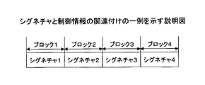
また、衝突許容チャネル生成部112は、シグネチャ系列に制御情報を示す系列を乗算するようにしてもよい。例えば、衝突許容チャネル生成部112は、図6に示すように、制御情報を示すシンボル系列、例えば“+1”、“−1”、“+1”、“−1”に、シグネチャ系列、例えば“シグネチャ1”、“シグネチャ2”、“シグネチャ3”、“シグネチャ4”を乗算し、階層的プリアンブル系列を生成する。
Further, the collision permissible
ここで、制御情報を示すシンボル系列としては、Walsh系列、GCL系列など直交系列を用いる。このようにすることにより、互いに直交する(相互相関がゼロ)ので、検出精度が高い。例えば、Walsh系列ならHadmard変換、GCLならDFT変換により、簡易に検出が可能である。 Here, orthogonal sequences such as Walsh sequences and GCL sequences are used as symbol sequences indicating control information. By doing so, the detection accuracy is high because they are orthogonal to each other (cross-correlation is zero). For example, detection can be easily performed by Hadmard conversion for the Walsh series and DFT conversion for the GCL.
また、ランダム変調系列を用いるようにしてもよい。このようにすることにより、送ることのできるビット数を増大させることができる。 Further, a random modulation sequence may be used. In this way, the number of bits that can be sent can be increased.
また、符号化系列を用いるようにしてもよい。例えば、制御情報を畳み込み符号化などチャネル符号化した系列を用いる。プリアンブルのブロック数が十分大きくないと符号化利得が得られないが、ブロック数が十分大きければ,ビット数も大きく取れ、検出精度も符号化利得により高くできる。 Also, an encoded sequence may be used. For example, a sequence obtained by channel-coding control information such as convolutional coding is used. If the number of preamble blocks is not sufficiently large, an encoding gain cannot be obtained. However, if the number of blocks is sufficiently large, the number of bits can be increased and the detection accuracy can be increased by the encoding gain.
受信側の処理としては、以下の構成が考えられる。 The following configuration can be considered as processing on the receiving side.
まず、各ブロックのシグネチャを検出してから、制御情報を示すシンボル系列を検出する。このようにすることにより、比較的簡単な処理でシグネチャおよびシンボル系列を検出することができる。 First, after detecting the signature of each block, a symbol series indicating control information is detected. By doing in this way, a signature and a symbol series can be detected by a relatively simple process.
また、各ブロックのシグネチャと制御情報を示すシンボル系列の検出をまとめて行うようにしてもよい。このようにすることにより、検出精度を向上させることができる。 Further, the detection of the symbol series indicating the signature and control information of each block may be performed collectively. By doing in this way, detection accuracy can be improved.
また、衝突許容チャネル生成部112は、制御ビット数自体を削減するようにしてもよい。衝突許容チャネル生成部112は、複数の他の制御ビットの組み合わせにより、ランダム仮IDを示す。
Further, the collision permissible
例えば、衝突許容チャネル生成部112は、図7に示すように、ランダム仮IDで送信する場合(Initial access)、制御情報として、目的識別子、下りリンクCQI、スケジューリング要求情報およびシグネチャ番号を生成する。ここで、衝突許容チャネル生成部112は、スケジューリング要求情報およびシグネチャ番号の部分の系列をランダム仮IDとみなす。ここで、目的識別子としては、例えばIDLE状態のランダムアクセスの場合には、ランダム仮IDが使用されていることを示す“0”が格納される。
For example, as illustrated in FIG. 7, the collision permissible
また、例えば、衝突許容チャネル生成部112は、図8に示すように、同期外れ、ハンドオーバが行われ、UE−IDで送信する場合、制御情報として、目的識別子、下りリンクCQI、UE−IDを生成する。ここで、UE−IDには、UE−IDに応じて決定されるシグネチャ番号が格納される。ここで、目的識別子としては、例えばActive状態のランダムアクセスであることを示す“1”が格納される。UE―IDで送信する場合、スケジューリング要求情報は送信済みである。
In addition, for example, as illustrated in FIG. 8, when the collision-acceptable
このようにすることにより、目的識別子により、どちらのフォーマット、すなわちランダム仮IDにより送信されるフォーマットであるか、UE−IDで送信されるフォーマットであるかを受信側で識別できる。また、ランダム仮IDを別のビットで送信する必要がない。また、UE−IDを送信する場合と同じ制御ビット数で送信することができる。 By doing so, the receiving side can identify which format, that is, the format transmitted by the random temporary ID or the format transmitted by the UE-ID, by the purpose identifier. Further, it is not necessary to transmit the random temporary ID with another bit. Moreover, it can transmit with the same control bit number as the case where UE-ID is transmitted.
次に、本発明の実施例にかかる受信装置200について、図9を参照して説明する。
Next, a receiving
本実施例にかかる受信装置200は、例えば基地局に備えられ、アンテナを備える低雑音増幅器(Low Noise Amplifier:LNA)102と、LNA102の出力信号が入力されるRFフィルタ104と、RFフィルタ104の出力信号が入力されるダウンコンバータ106と、ダウンコンバータ106の出力信号が入力されるIFフィルタ108と、IFフィルタの出力信号が入力されるD/Aコンバータ110と、D/Aコンバータ110の出力信号が入力される帯域制限フィルタ112と、帯域制限フィルタ112の出力信号が入力される検出処理手段としてのプリアンブル部検出処理部114および制御メッセージ部検出処理部116と、帯域制限フィルタ112、プリアンブル部検出処理部114および制御メッセージ部検出処理部116を制御する制御手段としてのホッピングパターン中心周波数制御部118とを備える。
The receiving
受信信号は、LNA102において処理に適した振幅に増幅され、ダウンコンバータ106に入力される。ダウンコンバータ106は、増幅された受信信号から中間周波数(IF)に低下した信号を発生し、IFフィルタ108に入力する。IFフィルタ108は、IF信号を受信信号の特定周波数帯域に制限する。帯域制限された信号は、D/Aコンバータ110に入力され、帯域制限フィルタ112において帯域制限され、プリアンブル部検出処理部114およびL1/L2制御メッセージ部検出処理部116に入力される。
The received signal is amplified to an amplitude suitable for processing in the
ホッピングパターン・中心周波数制御部118は、自基地局がランダムアクセスチャネルのために割り当てを行っている既知のホッピングパターン、中心周波数の情報に基づいて、帯域制限フィルタ112、プリアンブル部検出処理部114、制御メッセージ部検出処理部116の制御を行う。
The hopping pattern / center frequency control unit 118 includes a
プリアンブル部検出処理部114はプリアンブル部の検出を行い、プリアンブル部(シグネチャ)の検出情報を出力する。また、制御メッセージ部検出処理部116は制御メッセージ部の検出を行い、制御情報を出力する。
The preamble part
プリアンブル部検出処理部114は、受信されたランダムアクセスチャネルからプリアンブル部の検出および復調を行う。複数の移動局は、複数のコードのうち、1つを選択してランダムアクセスチャネルを送信する。プリアンブル部検出処理部114は、シグネチャと制御情報とが関連付けられている場合、プリアンブル部を復調することにより、得られた制御情報を制御メッセージ部検出処理部116に入力する。
The preamble part
また、プリアンブル部検出処理部114は、プリアンブル部が複数のブロックに分けられ、各ブロックで異なるシグネチャの組み合わせが送信された場合、例えば各ブロックで16種類のうちの1つのシグネチャが送信された場合、ブロック毎に16通りのシグネチャを検出し、相関検出値のブロック間の合計値の計算を行う。このようにすることにより、プリアンブル部で送信された多くの制御ビットを検出することができる。
In addition, the preamble part
また、シグネチャ系列に制御情報を示す系列が乗算されて送信された場合、プリアンブル部検出処理部114は、各ブロックのシグネチャを検出し、制御情報を示すシンボル系列を検出する。プリアンブル部検出処理部114は、検出した制御情報を制御メッセージ部検出処理部116に入力する。このようにすることにより、比較的簡単に検出処理を行うことができる。
Also, when the signature sequence is transmitted after being multiplied by the sequence indicating the control information, the preamble part
また、この場合、プリアンブル部検出処理部114は、各ブロックのシグネチャと制御情報を示すシンボル系列の検出をまとめて行うようにしてもよい。プリアンブル部検出処理部114は、検出した制御情報を制御メッセージ部検出処理部116に入力する。このようにすることにより、検出精度を向上させることができる。
Further, in this case, the preamble part
次に、本実施例にかかる無線通信システムの動作について説明する。 Next, the operation of the wireless communication system according to the present embodiment will be described.
IDLEモードからACTIVEモードに遷移する場合について、図10を参照して説明する。 A case of transition from the IDLE mode to the ACTIVE mode will be described with reference to FIG.
移動局(UE)は、ランダムアクセスチャネル(RACH)を基地局(Node B)に送信する(ステップS1002)。例えば、移動局はランダム仮IDによりRACHを基地局に送信する。 The mobile station (UE) transmits a random access channel (RACH) to the base station (Node B) (step S1002). For example, the mobile station transmits the RACH to the base station using a random temporary ID.
次に、基地局は、上りリソース割当(Uplink data resource allocation)と、タイミング情報(Timing information)を移動局に通知する(ステップS1004)
次に、基地局は、セル固有のID(Cell specific UE ID(C−RNTI))を移動局に通知する(ステップS1006)。
Next, the base station notifies uplink resource allocation (Uplink data resource allocation) and timing information (Timing information) to the mobile station (step S1004).
Next, the base station notifies the mobile station of a cell-specific ID (Cell specific UE ID (C-RNTI)) (step S1006).
次に、移動局は、共有データチャネル(Shared data channel)を基地局に送信する(ステップS1008)。移動局は、RRC+NASを送信し、コネクションオープンリクエスト(connection open request)を行う。 Next, the mobile station transmits a shared data channel (Shared data channel) to the base station (step S1008). The mobile station transmits RRC + NAS and makes a connection open request.
次に、基地局は、コネクションオープンリスポンス(connection open response)を移動局に通知する。 Next, the base station notifies the mobile station of a connection open response (connection open response).
次に、移動局と基地局は、共有データチャネルにより、データの送受信を行う。 Next, the mobile station and the base station perform data transmission / reception via the shared data channel.
ドーマント状態からアクティブ状態またはハンドオーバ状態に遷移する場合について、図11を参照して説明する。 A case of transition from the dormant state to the active state or the handover state will be described with reference to FIG.
移動局は、ランダムアクセスチャネル(RACH)を基地局に送信する(ステップS1102)。例えば、移動局はUE−IDによりRACHを基地局に送信する。 The mobile station transmits a random access channel (RACH) to the base station (step S1102). For example, the mobile station transmits the RACH to the base station using the UE-ID.
次に、基地局は、上りリソース割当(Uplink data resource allocation)と、タイミング情報(Timing information)を移動局に通知する(ステップS1104)
次に、移動局と基地局は、共有データチャネルにより、データの送受信を行う(ステップS1106)。
Next, the base station reports uplink resource allocation (Uplink data resource allocation) and timing information (Timing information) to the mobile station (step S1104).
Next, the mobile station and the base station perform data transmission / reception via the shared data channel (step S1106).
本発明にかかる送信装置および受信装置並びにランダムアクセス制御方法は、無線通信システムに適用できる。 The transmission device, the reception device, and the random access control method according to the present invention can be applied to a wireless communication system.
100 送信装置
200 受信装置
100
Claims (8)
少なくとも制御情報の一部を含むプリアンブル部から構成されるランダムアクセスチャネルを生成するランダムアクセスチャネル生成手段;
各ユーザに対して、連続的な周波数割り当ておよび非連続的なくしの歯状の周波数割り当てのうちの一方を行う割り当てを行い、前記ランダムアクセスチャネルを可変のマルチ帯域幅で送信する送信制御手段;
を備えることを特徴とする送信装置。 Among the frequency bands allocated to collision-acceptable channels,
Random access channel generating means for generating a random access channel configured by a preamble part including at least part of control information;
Transmission control means for assigning each user one of continuous frequency assignment and non-continuous comb-like frequency assignment, and transmitting the random access channel with a variable multi-bandwidth;
A transmission device comprising:
前記ランダムアクセスチャネル生成手段は、移動局から送信されるCQI情報に基づいて予めグループ分けされたシグネチャ番号を生成することを特徴とする送信装置。 In the transmitting device according to claim 1:
The transmission apparatus according to claim 1, wherein the random access channel generation unit generates signature numbers grouped in advance based on CQI information transmitted from a mobile station.
前記プリアンブル部は、複数のブロックに分割され、
前記ランダムアクセスチャネル生成手段は、ブロック毎にシグネチャ番号を生成することを特徴とする送信装置。 In the transmission device according to claim 1 or 2,
The preamble part is divided into a plurality of blocks,
The transmission apparatus according to claim 1, wherein the random access channel generation unit generates a signature number for each block.
前記ランダムアクセスチャネル生成手段は、各ブロックにおいて、制御情報を示すシンボル系列にシグネチャ系列を乗算し、プリアンブル部を構成する系列を生成することを特徴とする送信装置。 In the transmission device according to claim 3:
The random access channel generation means, in each block, multiplies a symbol sequence indicating control information by a signature sequence to generate a sequence constituting a preamble part.
前記ランダムアクセスチャネル生成手段は、目的識別子、下りリンクCQI、スケジューリング要求情報およびシグネチャ番号から構成されるランダムアクセスチャネルを生成し、
前記スケジューリング要求情報およびシグネチャ番号は、ランダムアクセスを行う場合の仮のIDを示すことを特徴とする送信装置。 In the transmitting device according to claim 1:
The random access channel generation means generates a random access channel including a purpose identifier, a downlink CQI, scheduling request information, and a signature number,
The transmission apparatus according to claim 1, wherein the scheduling request information and the signature number indicate a temporary ID when performing random access.
前記ランダムアクセスチャネル生成手段は、目的識別子、下りリンクCQI、ユーザIDから構成されるランダムアクセスチャネルを生成し、
前記ユーザIDに応じて、シグネチャが決定されることを特徴とする送信装置。 In the transmitting device according to claim 1:
The random access channel generation means generates a random access channel including a purpose identifier, a downlink CQI, and a user ID,
A transmission apparatus, wherein a signature is determined according to the user ID.
前記ランダムアクセスチャネルからプリアンブル部および制御メッセージ部の検出を行う検出処理手段;
を備え、
前記検出処理手段は、前記プリアンブル部が複数のブロックに分割され、各ブロックにおいて制御情報を示すシンボル系列にシグネチャ系列が乗算されている場合、各ブロックのシグネチャを検出し、制御情報を示すシンボル系列を検出することを特徴とする受信装置。 Receiving means for receiving a random access channel from one or more mobile stations;
Detection processing means for detecting a preamble part and a control message part from the random access channel;
With
The detection processing means detects the signature of each block when the preamble part is divided into a plurality of blocks and a symbol sequence indicating control information is multiplied in each block, and a symbol sequence indicating control information A receiving apparatus for detecting
少なくとも制御情報の一部を含むプリアンブル部から構成されるランダムアクセスチャネルを生成するランダムアクセスチャネル生成ステップ;
各ユーザに対して、連続的な周波数割り当ておよび非連続的なくしの歯状の周波数割り当てのうちの一方を行う割り当てステップ;
前記ランダムアクセスチャネルを可変のマルチ帯域幅で送信する送信ステップ;
を有することを特徴とするランダムアクセス制御方法。 Among the frequency bands allocated to collision-acceptable channels,
A random access channel generation step of generating a random access channel including a preamble part including at least a part of control information;
An assigning step for each user, one of continuous frequency assignment and non-continuous comb-like frequency assignment;
Transmitting the random access channel with variable multi-bandwidth;
A random access control method comprising:
Priority Applications (9)
| Application Number | Priority Date | Filing Date | Title |
|---|---|---|---|
| JP2006127994A JP4732948B2 (en) | 2006-05-01 | 2006-05-01 | Transmitting apparatus, receiving apparatus, and random access control method |
| RU2008146106/09A RU2008146106A (en) | 2006-05-01 | 2007-04-19 | SENDING DEVICE, RECEIVING DEVICE AND METHOD OF CONTROLLING ARBITRARY ACCESS |
| EP07741974A EP2015594A4 (en) | 2006-05-01 | 2007-04-19 | Transmission device, reception device, and random access control method |
| US12/299,272 US8289931B2 (en) | 2006-05-01 | 2007-04-19 | Transmitting device, receiving device, and random access control method |
| CN2007800239966A CN101480101B (en) | 2006-05-01 | 2007-04-19 | Transmission device, reception device, and random access control method |
| BRPI0709757-3A BRPI0709757A2 (en) | 2006-05-01 | 2007-04-19 | transmitting device, receiving device and random access control method |
| KR1020087028832A KR101287911B1 (en) | 2006-05-01 | 2007-04-19 | Transmission device, reception device, and random access control method |
| PCT/JP2007/058538 WO2007129540A1 (en) | 2006-05-01 | 2007-04-19 | Transmission device, reception device, and random access control method |
| TW96114395A TW200803247A (en) | 2006-05-01 | 2007-04-24 | Transmission device, reception device, and random access control method |
Applications Claiming Priority (1)
| Application Number | Priority Date | Filing Date | Title |
|---|---|---|---|
| JP2006127994A JP4732948B2 (en) | 2006-05-01 | 2006-05-01 | Transmitting apparatus, receiving apparatus, and random access control method |
Publications (2)
| Publication Number | Publication Date |
|---|---|
| JP2007300505A JP2007300505A (en) | 2007-11-15 |
| JP4732948B2 true JP4732948B2 (en) | 2011-07-27 |
Family
ID=38667649
Family Applications (1)
| Application Number | Title | Priority Date | Filing Date |
|---|---|---|---|
| JP2006127994A Active JP4732948B2 (en) | 2006-05-01 | 2006-05-01 | Transmitting apparatus, receiving apparatus, and random access control method |
Country Status (9)
| Country | Link |
|---|---|
| US (1) | US8289931B2 (en) |
| EP (1) | EP2015594A4 (en) |
| JP (1) | JP4732948B2 (en) |
| KR (1) | KR101287911B1 (en) |
| CN (1) | CN101480101B (en) |
| BR (1) | BRPI0709757A2 (en) |
| RU (1) | RU2008146106A (en) |
| TW (1) | TW200803247A (en) |
| WO (1) | WO2007129540A1 (en) |
Families Citing this family (31)
| Publication number | Priority date | Publication date | Assignee | Title |
|---|---|---|---|---|
| JP4711835B2 (en) * | 2006-01-17 | 2011-06-29 | 株式会社エヌ・ティ・ティ・ドコモ | Transmitting apparatus, receiving apparatus, and random access control method |
| US7970427B2 (en) * | 2007-03-20 | 2011-06-28 | Skyworks Solutions, Inc. | System and method for dynamically improving call connection |
| CN101772932B (en) | 2007-08-08 | 2014-12-10 | 知识产权之桥一号有限责任公司 | Radio communication base station device and correlation setting method |
| US8340014B2 (en) | 2007-12-26 | 2012-12-25 | Lg Electronics Inc. | Method for transmitting and receiving signals using multi-band radio frequencies |
| CN101911806B (en) * | 2007-12-29 | 2013-09-04 | 上海贝尔股份有限公司 | Persistent scheduling method and apparatus based on semi-grouping and statistically multiplexing |
| US8489028B2 (en) | 2008-05-22 | 2013-07-16 | Qualcomm Incorporated | System and method to enable resource partitioning in wireless networks |
| US8554147B2 (en) * | 2008-05-22 | 2013-10-08 | Qualcomm Incorporated | System and method to enable resource partitioning in wireless networks |
| KR100968020B1 (en) | 2008-06-18 | 2010-07-08 | 엘지전자 주식회사 | Method for performing random access procedures and terminal thereof |
| GB2461158B (en) * | 2008-06-18 | 2011-03-02 | Lg Electronics Inc | Method for performing random access procedures and terminal therof |
| US11272449B2 (en) | 2008-06-18 | 2022-03-08 | Optis Cellular Technology, Llc | Method and mobile terminal for performing random access |
| US8964659B2 (en) | 2009-02-02 | 2015-02-24 | Lg Electronics Inc. | Random access channel resource allocation |
| US8406781B2 (en) * | 2009-02-02 | 2013-03-26 | Lg Electronics Inc. | Determination of user equipment antenna capability |
| KR101307630B1 (en) * | 2009-03-23 | 2013-09-12 | 후지쯔 가부시끼가이샤 | Radio communication system, base station device, terminal, and radio communication method in radio communication system |
| IL197881A (en) * | 2009-03-24 | 2015-10-29 | Sparkmotion Inc | Method for handling corrupted signals in a wireless network |
| WO2010146980A1 (en) * | 2009-06-16 | 2010-12-23 | シャープ株式会社 | Mobile station device, base station device, communication system and random access method |
| JP5344045B2 (en) | 2009-09-30 | 2013-11-20 | 富士通株式会社 | Wireless communication apparatus and wireless communication method |
| CN102577555B (en) | 2009-10-02 | 2015-09-16 | 富士通株式会社 | Wireless communications method in wireless communication system, base station apparatus, terminal installation and wireless communication system |
| MX2012009337A (en) * | 2010-02-12 | 2012-11-29 | Fujitsu Ltd | Wireless communication apparatus, wireless communication system and wireless communication method. |
| CN104093824B (en) | 2012-02-06 | 2018-05-11 | 巴斯夫欧洲公司 | Cleaning combination after chemically mechanical polishing comprising specific sulfur-containing compound and sugar alcohol or polybasic carboxylic acid |
| JP6092521B2 (en) * | 2012-04-06 | 2017-03-08 | 株式会社Nttドコモ | Communication system, mobile terminal apparatus, local area base station apparatus, and communication method |
| JP5798664B2 (en) * | 2012-12-28 | 2015-10-21 | 株式会社Agoop | Program, information processing apparatus and method |
| JP5632032B2 (en) | 2012-12-28 | 2014-11-26 | 株式会社Agoop | Program, information processing apparatus and method |
| US9641303B2 (en) | 2013-09-09 | 2017-05-02 | Huawei Technologies Co., Ltd. | System and method for increasing low density signature space |
| EP3304752A1 (en) * | 2015-07-03 | 2018-04-11 | Huawei Technologies Co., Ltd. | Device and method for transmitting and receiving emergency signals using a wireless communication network |
| US10129052B2 (en) | 2015-08-14 | 2018-11-13 | Qualcomm Incorporated | Phase noise estimation |
| US11191097B2 (en) | 2015-08-17 | 2021-11-30 | Qualcomm Incorporated | Reception of multiple uplink control messages at a same time slot |
| CN109314999B (en) * | 2016-08-16 | 2023-03-24 | Oppo广东移动通信有限公司 | Method and device for transmitting information |
| WO2019077717A1 (en) * | 2017-10-19 | 2019-04-25 | 三菱電機株式会社 | Communication device and communication method |
| KR102457566B1 (en) * | 2018-02-22 | 2022-10-21 | 한국전자통신연구원 | Modem performing modulation or demodulation based on length of burst in a data packet and a method performed by the modem |
| WO2021229094A1 (en) * | 2020-05-15 | 2021-11-18 | Telefonaktiebolaget Lm Ericsson (Publ) | Adapting periodic configurations based on spatial relations |
| JP7086160B2 (en) * | 2020-11-25 | 2022-06-17 | オッポ広東移動通信有限公司 | Information transmission method and device |
Family Cites Families (13)
| Publication number | Priority date | Publication date | Assignee | Title |
|---|---|---|---|---|
| FI105741B (en) * | 1998-02-12 | 2000-09-29 | Nokia Networks Oy | Communication method and radio system |
| JP3116895B2 (en) * | 1998-03-30 | 2000-12-11 | 日本電気株式会社 | IS-95 base station, W-CDMA base station, mobile communication system, and frequency sharing method |
| GB9823467D0 (en) * | 1998-10-28 | 1998-12-23 | Koninkl Philips Electronics Nv | Radio communication system |
| DK1142149T3 (en) * | 1998-12-14 | 2004-07-26 | Interdigital Tech Corp | Random access channel preamble detection |
| US6535547B1 (en) * | 1999-06-02 | 2003-03-18 | Telefonaktiebolaget Lm Ericsson (Publ) | Random access in a mobile telecommunications system |
| CN1136673C (en) * | 2000-01-14 | 2004-01-28 | 松下电器产业株式会社 | Radio base station device and radio communication method |
| JP3735056B2 (en) * | 2001-10-09 | 2006-01-11 | 株式会社日立国際電気 | CDMA radio base station |
| JP4276009B2 (en) * | 2003-02-06 | 2009-06-10 | 株式会社エヌ・ティ・ティ・ドコモ | Mobile station, base station, radio transmission program, and radio transmission method |
| JP4762619B2 (en) * | 2004-07-14 | 2011-08-31 | パナソニック株式会社 | Communication terminal device and wireless communication method |
| US9137822B2 (en) * | 2004-07-21 | 2015-09-15 | Qualcomm Incorporated | Efficient signaling over access channel |
| JP3846802B2 (en) | 2004-10-29 | 2006-11-15 | Tdk株式会社 | Discharge lamp driving device and liquid crystal display device |
| CN101346906B (en) * | 2005-12-23 | 2013-10-16 | Lg电子株式会社 | Random access procedure processing method |
| US9301318B2 (en) * | 2006-01-20 | 2016-03-29 | Nokia Technologies Oy | Random access procedure with enhanced coverage |
-
2006
- 2006-05-01 JP JP2006127994A patent/JP4732948B2/en active Active
-
2007
- 2007-04-19 RU RU2008146106/09A patent/RU2008146106A/en not_active Application Discontinuation
- 2007-04-19 WO PCT/JP2007/058538 patent/WO2007129540A1/en active Application Filing
- 2007-04-19 KR KR1020087028832A patent/KR101287911B1/en active IP Right Grant
- 2007-04-19 EP EP07741974A patent/EP2015594A4/en not_active Withdrawn
- 2007-04-19 CN CN2007800239966A patent/CN101480101B/en not_active Expired - Fee Related
- 2007-04-19 BR BRPI0709757-3A patent/BRPI0709757A2/en not_active IP Right Cessation
- 2007-04-19 US US12/299,272 patent/US8289931B2/en active Active
- 2007-04-24 TW TW96114395A patent/TW200803247A/en unknown
Also Published As
| Publication number | Publication date |
|---|---|
| JP2007300505A (en) | 2007-11-15 |
| TW200803247A (en) | 2008-01-01 |
| CN101480101B (en) | 2010-12-15 |
| KR20090009263A (en) | 2009-01-22 |
| WO2007129540A1 (en) | 2007-11-15 |
| KR101287911B1 (en) | 2013-07-19 |
| US8289931B2 (en) | 2012-10-16 |
| BRPI0709757A2 (en) | 2011-07-26 |
| EP2015594A1 (en) | 2009-01-14 |
| US20090219873A1 (en) | 2009-09-03 |
| CN101480101A (en) | 2009-07-08 |
| EP2015594A4 (en) | 2012-12-26 |
| RU2008146106A (en) | 2010-06-10 |
Similar Documents
| Publication | Publication Date | Title |
|---|---|---|
| JP4732948B2 (en) | Transmitting apparatus, receiving apparatus, and random access control method | |
| JP4711835B2 (en) | Transmitting apparatus, receiving apparatus, and random access control method | |
| US10225060B2 (en) | Apparatus and method for allocating code resources to uplink ACK/NACK channels in a cellular wireless communication system | |
| KR101449556B1 (en) | User device, base station device, and method | |
| CA2289645C (en) | Channel communication device and method for cdma communication system | |
| EP2139256B1 (en) | Base station device, mobile station and wireless communication system, and communication control method | |
| JP4184969B2 (en) | Signal measuring apparatus and method for handover in a mobile communication system | |
| EP2184873B1 (en) | Base station apparatus, transmitting method, and radio communication system | |
| JP4932419B2 (en) | Mobile communication system | |
| US20020150058A1 (en) | Apparatus and method for randomly controlling time slot of sub-frame in an NB-TDD CDMA system | |
| US20050169295A1 (en) | Apparatus and method for gating transmission of a data rate control channel in an HDR mobile communication system | |
| KR20110053988A (en) | User device and cell search method | |
| KR100350466B1 (en) | apparatus and method for implementing hand-off in mobile communication system having short sync channel | |
| JP3911378B2 (en) | Communication terminal device and communication method | |
| CN108633092B (en) | Information sending method, device and terminal | |
| US7940739B2 (en) | Complex multiplexing transmission/reception apparatus and method in a wireless communication system | |
| JP6856726B2 (en) | Communication equipment, communication methods and integrated circuits | |
| KR20010028203A (en) | apparatus and method for implementing hand-off from asynchronous mobile communication system to synchronous mobile communication system having auxiliary sync channels | |
| JP7027581B2 (en) | Terminals, communication methods and integrated circuits | |
| JP2006313981A (en) | Communication terminal device, base station device, and base station device selecting method | |
| JP2006129397A (en) | Communication apparatus, base station device and transmission method |
Legal Events
| Date | Code | Title | Description |
|---|---|---|---|
| A621 | Written request for application examination |
Free format text: JAPANESE INTERMEDIATE CODE: A621 Effective date: 20090220 |
|
| TRDD | Decision of grant or rejection written | ||
| A01 | Written decision to grant a patent or to grant a registration (utility model) |
Free format text: JAPANESE INTERMEDIATE CODE: A01 Effective date: 20110419 |
|
| A01 | Written decision to grant a patent or to grant a registration (utility model) |
Free format text: JAPANESE INTERMEDIATE CODE: A01 |
|
| A61 | First payment of annual fees (during grant procedure) |
Free format text: JAPANESE INTERMEDIATE CODE: A61 Effective date: 20110421 |
|
| FPAY | Renewal fee payment (event date is renewal date of database) |
Free format text: PAYMENT UNTIL: 20140428 Year of fee payment: 3 |
|
| R150 | Certificate of patent or registration of utility model |
Ref document number: 4732948 Country of ref document: JP Free format text: JAPANESE INTERMEDIATE CODE: R150 Free format text: JAPANESE INTERMEDIATE CODE: R150 |
|
| R250 | Receipt of annual fees |
Free format text: JAPANESE INTERMEDIATE CODE: R250 |
|
| R250 | Receipt of annual fees |
Free format text: JAPANESE INTERMEDIATE CODE: R250 |
|
| R250 | Receipt of annual fees |
Free format text: JAPANESE INTERMEDIATE CODE: R250 |
|
| R250 | Receipt of annual fees |
Free format text: JAPANESE INTERMEDIATE CODE: R250 |
|
| R250 | Receipt of annual fees |
Free format text: JAPANESE INTERMEDIATE CODE: R250 |
|
| R250 | Receipt of annual fees |
Free format text: JAPANESE INTERMEDIATE CODE: R250 |
|
| R250 | Receipt of annual fees |
Free format text: JAPANESE INTERMEDIATE CODE: R250 |
|
| R250 | Receipt of annual fees |
Free format text: JAPANESE INTERMEDIATE CODE: R250 |
|
| R250 | Receipt of annual fees |
Free format text: JAPANESE INTERMEDIATE CODE: R250 |
|
| R250 | Receipt of annual fees |
Free format text: JAPANESE INTERMEDIATE CODE: R250 |