JP4732935B2 - Base station, mobile station and method - Google Patents
Base station, mobile station and method Download PDFInfo
- Publication number
- JP4732935B2 JP4732935B2 JP2006077822A JP2006077822A JP4732935B2 JP 4732935 B2 JP4732935 B2 JP 4732935B2 JP 2006077822 A JP2006077822 A JP 2006077822A JP 2006077822 A JP2006077822 A JP 2006077822A JP 4732935 B2 JP4732935 B2 JP 4732935B2
- Authority
- JP
- Japan
- Prior art keywords
- rate
- filter
- base station
- uplink
- radio
- Prior art date
- Legal status (The legal status is an assumption and is not a legal conclusion. Google has not performed a legal analysis and makes no representation as to the accuracy of the status listed.)
- Expired - Fee Related
Links
Images


Classifications
-
- H—ELECTRICITY
- H04—ELECTRIC COMMUNICATION TECHNIQUE
- H04L—TRANSMISSION OF DIGITAL INFORMATION, e.g. TELEGRAPHIC COMMUNICATION
- H04L1/00—Arrangements for detecting or preventing errors in the information received
- H04L1/0001—Systems modifying transmission characteristics according to link quality, e.g. power backoff
- H04L1/0002—Systems modifying transmission characteristics according to link quality, e.g. power backoff by adapting the transmission rate
- H04L1/0003—Systems modifying transmission characteristics according to link quality, e.g. power backoff by adapting the transmission rate by switching between different modulation schemes
-
- H—ELECTRICITY
- H04—ELECTRIC COMMUNICATION TECHNIQUE
- H04L—TRANSMISSION OF DIGITAL INFORMATION, e.g. TELEGRAPHIC COMMUNICATION
- H04L1/00—Arrangements for detecting or preventing errors in the information received
- H04L1/0001—Systems modifying transmission characteristics according to link quality, e.g. power backoff
- H04L1/0009—Systems modifying transmission characteristics according to link quality, e.g. power backoff by adapting the channel coding
-
- H—ELECTRICITY
- H04—ELECTRIC COMMUNICATION TECHNIQUE
- H04L—TRANSMISSION OF DIGITAL INFORMATION, e.g. TELEGRAPHIC COMMUNICATION
- H04L25/00—Baseband systems
- H04L25/02—Details ; arrangements for supplying electrical power along data transmission lines
- H04L25/0202—Channel estimation
- H04L25/0222—Estimation of channel variability, e.g. coherence bandwidth, coherence time, fading frequency
-
- H—ELECTRICITY
- H04—ELECTRIC COMMUNICATION TECHNIQUE
- H04L—TRANSMISSION OF DIGITAL INFORMATION, e.g. TELEGRAPHIC COMMUNICATION
- H04L25/00—Baseband systems
- H04L25/02—Details ; arrangements for supplying electrical power along data transmission lines
- H04L25/03—Shaping networks in transmitter or receiver, e.g. adaptive shaping networks
- H04L25/03828—Arrangements for spectral shaping; Arrangements for providing signals with specified spectral properties
-
- H—ELECTRICITY
- H04—ELECTRIC COMMUNICATION TECHNIQUE
- H04W—WIRELESS COMMUNICATION NETWORKS
- H04W28/00—Network traffic management; Network resource management
- H04W28/16—Central resource management; Negotiation of resources or communication parameters, e.g. negotiating bandwidth or QoS [Quality of Service]
- H04W28/18—Negotiating wireless communication parameters
-
- H—ELECTRICITY
- H04—ELECTRIC COMMUNICATION TECHNIQUE
- H04W—WIRELESS COMMUNICATION NETWORKS
- H04W48/00—Access restriction; Network selection; Access point selection
- H04W48/08—Access restriction or access information delivery, e.g. discovery data delivery
-
- H—ELECTRICITY
- H04—ELECTRIC COMMUNICATION TECHNIQUE
- H04L—TRANSMISSION OF DIGITAL INFORMATION, e.g. TELEGRAPHIC COMMUNICATION
- H04L27/00—Modulated-carrier systems
- H04L27/26—Systems using multi-frequency codes
- H04L27/2601—Multicarrier modulation systems
- H04L27/2614—Peak power aspects
-
- H—ELECTRICITY
- H04—ELECTRIC COMMUNICATION TECHNIQUE
- H04L—TRANSMISSION OF DIGITAL INFORMATION, e.g. TELEGRAPHIC COMMUNICATION
- H04L27/00—Modulated-carrier systems
- H04L27/26—Systems using multi-frequency codes
- H04L27/2601—Multicarrier modulation systems
- H04L27/2626—Arrangements specific to the transmitter only
- H04L27/2627—Modulators
- H04L27/2634—Inverse fast Fourier transform [IFFT] or inverse discrete Fourier transform [IDFT] modulators in combination with other circuits for modulation
- H04L27/2636—Inverse fast Fourier transform [IFFT] or inverse discrete Fourier transform [IDFT] modulators in combination with other circuits for modulation with FFT or DFT modulators, e.g. standard single-carrier frequency-division multiple access [SC-FDMA] transmitter or DFT spread orthogonal frequency division multiplexing [DFT-SOFDM]
-
- H—ELECTRICITY
- H04—ELECTRIC COMMUNICATION TECHNIQUE
- H04L—TRANSMISSION OF DIGITAL INFORMATION, e.g. TELEGRAPHIC COMMUNICATION
- H04L5/00—Arrangements affording multiple use of the transmission path
- H04L5/0091—Signaling for the administration of the divided path
- H04L5/0094—Indication of how sub-channels of the path are allocated
-
- H—ELECTRICITY
- H04—ELECTRIC COMMUNICATION TECHNIQUE
- H04W—WIRELESS COMMUNICATION NETWORKS
- H04W28/00—Network traffic management; Network resource management
- H04W28/16—Central resource management; Negotiation of resources or communication parameters, e.g. negotiating bandwidth or QoS [Quality of Service]
- H04W28/18—Negotiating wireless communication parameters
- H04W28/20—Negotiating bandwidth
-
- H—ELECTRICITY
- H04—ELECTRIC COMMUNICATION TECHNIQUE
- H04W—WIRELESS COMMUNICATION NETWORKS
- H04W88/00—Devices specially adapted for wireless communication networks, e.g. terminals, base stations or access point devices
- H04W88/08—Access point devices
Landscapes
- Engineering & Computer Science (AREA)
- Signal Processing (AREA)
- Computer Networks & Wireless Communication (AREA)
- Quality & Reliability (AREA)
- Power Engineering (AREA)
- Physics & Mathematics (AREA)
- Spectroscopy & Molecular Physics (AREA)
- Computer Security & Cryptography (AREA)
- Mathematical Physics (AREA)
- General Physics & Mathematics (AREA)
- Discrete Mathematics (AREA)
- Mobile Radio Communication Systems (AREA)
- Communication Control (AREA)
Description
本発明は移動通信システムで使用される基地局、移動局及び方法に関する。 The present invention relates to a base station, a mobile station, and a method used in a mobile communication system.
現在研究開発が進められている次世代の無線アクセス方式では、従来の方式よりも更に効率的に通信を行うことが求められる。下りリンクでは通信の高速大容量化が特に必要とされ、そのため直交周波数分割多重接続(OFDM)のようなマルチキャリア方式の無線アクセス方式が有望視されている。これに対して上りリンクは下りリンクほど高速大容量化の要請は強くないこと及び移動局の送信電力は基地局のそれに比べて著しく制限されること等の点で、上りリンクは下りリンクと異なる。このため、ピーク電力対平均電力比(PAPR: peak to average power ratio)が大きくなるおそれのあるマルチキャリア方式は上りリンクに適切な方式とは言えない。むしろ、PAPRを抑制し、セルのカバレッジを大きくする観点からは、上りリンクにシングルキャリア方式を採用することが望ましい。 The next-generation wireless access system currently under research and development is required to perform communication more efficiently than the conventional system. In the downlink, high-speed and large-capacity communication is particularly required, and therefore, a multi-carrier wireless access method such as orthogonal frequency division multiple access (OFDM) is promising. On the other hand, the uplink is different from the downlink in that the request for higher speed and capacity is not as strong as the downlink and the transmission power of the mobile station is significantly limited compared to that of the base station. . For this reason, the multicarrier scheme that may increase the peak power to average power ratio (PAPR) cannot be said to be suitable for the uplink. Rather, from the viewpoint of suppressing PAPR and increasing cell coverage, it is desirable to adopt a single carrier scheme for the uplink.
ところで、次世代の無線アクセス方式では広範なシステム周波数帯域が用意され、その全部又は一部を用いて移動局が通信を行うことが想定されている。様々な上りリンクの帯域で適切にPAPRの抑制および隣接帯域へ及ぼす影響を低減する観点からは、帯域制限(波形整形又はスペクトル整形とも呼ばれる)を適切に行う必要がある。 By the way, in the next generation radio access system, a wide range of system frequency bands are prepared, and it is assumed that the mobile station performs communication using all or a part thereof. From the viewpoint of appropriately suppressing PAPR and reducing the influence on adjacent bands in various uplink bands, it is necessary to appropriately perform band limitation (also referred to as waveform shaping or spectrum shaping).
しかしながら従来の無線アクセス方式ではシステム周波数帯域は例えば5MHzに固定されており、帯域制限方式も固定されている。このような従来の技術が次世代の無線アクセス方式に使用されたとすると、適切な波形整形がなされないことに起因して、システム容量が制限されてしまうおそれがある。 However, in the conventional radio access system, the system frequency band is fixed at, for example, 5 MHz, and the band limiting system is also fixed. If such a conventional technique is used in the next generation radio access scheme, there is a risk that the system capacity may be limited due to the fact that appropriate waveform shaping is not performed.
なお、符号拡散後のチップデータ系列が二乗余弦ルートナイキストフィルタ(ロールオフファクタは0.22)で5MHzの帯域に帯域制限されることについては例えば非特許文献1に記載されている。
本発明の課題は、シングルキャリア方式の上りリンク無線アクセスにおけるシステム容量を向上させる基地局、移動局及び方法を提供することである。 An object of the present invention is to provide a base station, a mobile station, and a method for improving system capacity in single-carrier uplink radio access.
本発明では、上りリンクにシングルキャリア方式が使用される移動通信システムにおける基地局が使用される。基地局は、システム周波数帯域の全部又は一部を使用する移動局と通信を行う手段と、上りリンクの帯域幅、変調方式及びチャネル符号化率を含む無線パラメータと帯域制限フィルタのロールオフ率を少なくとも含むフィルタパラメータとの対応関係を記憶する記憶手段と、上りリンクのチャネル状態に応じて前記対応関係から移動局毎に無線パラメータ及びフィルタパラメータを決定する決定手段とを有する。決定手段で決定された無線パラメータ及びフィルタパラメータは移動局に通知される。 In the present invention, a base station in a mobile communication system in which a single carrier scheme is used for uplink is used. The base station communicates with a mobile station that uses all or part of the system frequency band, radio parameters including uplink bandwidth, modulation scheme and channel coding rate, and roll-off rate of the band limiting filter. Storage means for storing a correspondence relationship with at least filter parameters included, and a determination means for determining a radio parameter and a filter parameter for each mobile station from the correspondence relationship according to an uplink channel state. The radio parameters and filter parameters determined by the determining means are notified to the mobile station.
本発明によれば、シングルキャリア方式の上りリンク無線アクセスにおけるシステム容量を向上させることができる。 ADVANTAGE OF THE INVENTION According to this invention, the system capacity | capacitance in the uplink radio access of a single carrier system can be improved.
本発明の一形態では、上りリンクの帯域幅、変調方式及びチャネル符号化率を含む無線パラメータと帯域制限フィルタのロールオフ率を少なくとも含むフィルタパラメータとの対応関係が基地局で記憶される。上りリンクのチャネル状態に応じてその対応関係から移動局毎に無線パラメータ及びフィルタパラメータが決定され、移動局に通知される。これにより実際のチャネル状態に相応しい無線パラメータ及びフィルタパラメータが移動局に通知され、上りリンクの伝送効率が向上し、システム容量の増大を図ることができる。 In one embodiment of the present invention, a correspondence relationship between a radio parameter including an uplink bandwidth, a modulation scheme, and a channel coding rate and a filter parameter including at least a roll-off rate of a band limiting filter is stored in the base station. Radio parameters and filter parameters are determined for each mobile station from the corresponding relationship according to the uplink channel state, and are notified to the mobile station. As a result, radio parameters and filter parameters suitable for the actual channel state are notified to the mobile station, uplink transmission efficiency is improved, and system capacity can be increased.
対応関係は、より高速のビットレートの無線パラメータと、より小さなロールオフ率を対応付けてもよし、より低速のビットレートの無線パラメータと、より大きなロールオフ率を対応付けてもよい。 The correspondence relationship may associate a radio parameter with a higher bit rate with a smaller roll-off rate, or may associate a radio parameter with a lower bit rate with a larger roll-off rate.
対応関係は、より広い帯域幅と、より大きなロールオフ率を対応付けてもよいし、より狭い帯域幅と、より小さなロールオフ率を対応付けてもよい。 The correspondence relationship may associate a wider bandwidth with a larger roll-off rate, or may associate a narrower bandwidth with a smaller roll-off rate.
上りリンクの無線リソースの割当内容が更新される場合、変調方式及びチャネル符号化率の双方又は一方が変更されるとき、帯域幅の中心周波数が不変に維持されてもよい。このとき,前記帯域幅は変更されてもよい.(*これは,ロールオフフィルタを掛ける前の信号帯域を調整することで,よりシステム容量を増大できる効果があります.実施例図7で特に効果があると考えておりますが,特に図6の場合でも同じようにすることができます.)これはフィルタ調整の簡略化を図る観点から好ましい。 When the uplink radio resource allocation content is updated, the center frequency of the bandwidth may be maintained unchanged when both or one of the modulation scheme and the channel coding rate is changed. At this time, the bandwidth may be changed. (* This has the effect of increasing the system capacity by adjusting the signal bandwidth before the roll-off filter is applied. We believe that this is particularly effective in the example in Fig. 7, but in particular in Fig. 6. This is preferable from the viewpoint of simplifying the filter adjustment.
上りリンクの無線リソースの割当内容が更新される場合、変調方式及びチャネル符号化率の双方又は一方が変更されるとき、帯域幅の中心周波数の変更が許容されてもよい。このとき,前記帯域幅は変更されてもよい.これは伝送効率を更に高め、システム容量を向上させる観点から好ましい。 When the uplink radio resource allocation content is updated, a change in the center frequency of the bandwidth may be allowed when both or one of the modulation scheme and the channel coding rate is changed. At this time, the bandwidth may be changed. This is preferable from the viewpoint of further increasing the transmission efficiency and improving the system capacity.
図1は本発明の一実施例による移動通信システムを示す。図1には基地局BS及び移動局又はユーザ装置UEが描かれている。本実施例では上りリンクにシングルキャリア方式が採用され、PAPRが効果的に抑制される。移動局はシステム周波数帯域の全部又は一部を用いて通信を行う。例えば20MHzのシステム周波数帯域の内、1.25MHz,5MHz,10MHz等の帯域で移動局は通信を行う。また、無線伝送効率を向上させるため、適応変復調チャネル符号化(AMC:Adaptive Modulation and channel Coding)制御が行われ、変調方式及びチャネル符号化率がチャネル状態に応じて適応的に変更される。 FIG. 1 shows a mobile communication system according to an embodiment of the present invention. FIG. 1 shows a base station BS and a mobile station or user equipment UE. In this embodiment, a single carrier scheme is adopted for the uplink, and PAPR is effectively suppressed. The mobile station performs communication using all or part of the system frequency band. For example, the mobile station performs communication in a band such as 1.25 MHz, 5 MHz, and 10 MHz in the system frequency band of 20 MHz. In order to improve the radio transmission efficiency, adaptive modulation and channel coding (AMC) control is performed, and the modulation scheme and the channel coding rate are adaptively changed according to the channel state.
基地局は上りリンクのチャネル状態に応じて移動局が使用する帯域幅、変調方式及びチャネル符号化率を含む無線パラメータを決定する。無線パラメータの決定は、各移動局にどの無線リソースを割り当てるかを決定する(スケジューリングを行う)スケジューラで行われる。本実施例では移動局が上りリンクで使用する無線パラメータだけでなく、帯域制限を行うロールオフフィルタのロールオフ率及び通過帯域を含むフィルタパラメータも基地局が決定する。基地局で決定された無線リソース割り当て内容、無線パラメータ及びフィルタパラメータは、何らかの制御チャネルで移動局に通知される。移動局はその制御チャネルを受信し、無線パラメータ及びフィルタパラメータが何であるかを特定する。移動局は、通知された無線パラメータに従って、送信しようとする信号に対してデータ変調及びチャネル符号化を行う。移動局は、変調後の及びチャネル符号化後の信号に対して、波形整形(帯域制限)を行う。この帯域制限は、通知されたフィルタパラメータに従って行われる。帯域制限後の信号は、無線パラメータで指定される帯域幅で基地局に送信される。 The base station determines radio parameters including the bandwidth, modulation scheme, and channel coding rate used by the mobile station according to the uplink channel state. The radio parameter is determined by a scheduler that determines (schedules) which radio resource is allocated to each mobile station. In this embodiment, the base station determines not only the radio parameters used by the mobile station in the uplink, but also the filter parameters including the roll-off rate of the roll-off filter that performs band limitation and the pass band. The radio resource allocation content, radio parameters, and filter parameters determined by the base station are notified to the mobile station through some control channel. The mobile station receives the control channel and identifies what radio parameters and filter parameters are. The mobile station performs data modulation and channel coding on a signal to be transmitted according to the notified radio parameter. The mobile station performs waveform shaping (band limitation) on the modulated and channel-encoded signals. This band limitation is performed according to the notified filter parameter. The band-limited signal is transmitted to the base station with the bandwidth specified by the radio parameter.
次に、無線パラメータとフィルタパラメータの関係が説明される。 Next, the relationship between radio parameters and filter parameters will be described.
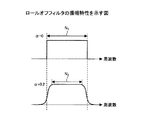
図2は帯域制限フィルタであるロールオフフィルタの振幅特性を示す。上側の図はロールオフ率又はロールオフ係数αが0である場合の振幅特性を示し、これはナイキスト周波数を境に通過域及び阻止域が階段状に急激に変わる理想的な低域通過フィルタに対応する。下側の図はロールオフ率αが0.2である場合の振幅特性を示す。ロールオフ率αは0以上1以下の値をとる。図示されているように、通過域(ロールオフフィルタを掛ける前の信号帯域)及び阻止域間は緩やかに変化するが、α=0の場合と比較して、占有帯域を同じにするためには,通過域N2を通過域N1より狭くする必要がある。すなわち,N1 = N2 x (1 + 0.2)の関係を満たすようなN2にする必要がある.(*図2を対応してご修正いただけますか?N1とN2
x (1+0.2)の帯域は等しい)この傾向はロールオフ率が大きくなるほど顕著になる。以下、様々な量とロールオフ率の関係が説明される。
FIG. 2 shows the amplitude characteristics of a roll-off filter which is a band limiting filter. The upper diagram shows the amplitude characteristics when the roll-off rate or roll-off coefficient α is 0. This is an ideal low-pass filter in which the passband and stopband change abruptly in steps from the Nyquist frequency. Correspond. The lower diagram shows the amplitude characteristics when the roll-off rate α is 0.2. The roll-off rate α takes a value from 0 to 1. As shown in the figure, the passband (the signal band before applying the roll-off filter) and the stopband change slowly, but in order to make the occupied band the same compared to the case of α = 0. , It is necessary to make the passband N 2 narrower than the passband N 1 . In other words, N2 must satisfy N1 = N2 x (1 + 0.2). (* Can you make corrections corresponding to Figure 2? N1 and N2
This tendency becomes more prominent as the roll-off rate increases. Hereinafter, the relationship between various amounts and the roll-off rate will be described.
(1)データ量とロールオフ率との関係
図2に示されるように、ロールオフ率αが増えると通過帯域Nは狭くなる。より多くのデータを伝送する観点からは通過帯域は広い方が好ましい。従って、データ伝送量を増やす観点からはロールオフ率αを小さくすること(理想的には、α=0)が望ましい。
(1) Relationship between Data Volume and Roll-off Rate As shown in FIG. 2, the pass band N becomes narrower as the roll-off rate α increases. From the viewpoint of transmitting more data, a wider pass band is preferable. Therefore, from the viewpoint of increasing the amount of data transmission, it is desirable to reduce the roll-off rate α (ideally α = 0).
(2)PAPRとロールオフ率との関係
図2に示されるように、ロールオフ率αが小さいほど、振幅特性は通過域及び阻止域間で急激に変化する。このことはロールオフ率が小さいと、時間領域の振幅特性でサイドローブ成分が大きくなり、PAPRを増やしてしまうことを意味する。従ってPAPRを小さく抑制する観点からは、ロールオフ率を大きくし、通過域及び阻止域間の変化を滑らにすることが望ましい。
(2) Relationship between PAPR and roll-off rate As shown in FIG. 2, the smaller the roll-off rate α, the more rapidly the amplitude characteristic changes between the passband and the stopband. This means that if the roll-off rate is small, the side lobe component becomes large due to the amplitude characteristics in the time domain and PAPR is increased. Therefore, from the viewpoint of suppressing PAPR to a small value, it is desirable to increase the roll-off rate and smooth the change between the passband and the stopband.
(3)隣接帯域へ及ぼす干渉とロールオフ率との関係
図2はナイキスト周波数の範囲内での理想的なフィルタ振幅特性を示す。しかしながら実際には図3に示されるようにナイキスト周波数fNを超える振幅特性を無視することはできず、これは隣接帯域へ及ぼす干渉になる。また、ナイキスト周波数fNが大きいほど隣接帯域に及ぼす干渉も大きく、ナイキスト周波数fNが小さいほど隣接帯域に及ぼす干渉は小さい、という傾向もある。この干渉は、図3に示されるようにロールオフフィルタ後の占有帯域fNが同じならば,ロールオフ率が小さいほど多く、ロールオフ率が大きいほど少ない。(*これは,図3の通りです.)α=0.2の場合の振幅特性は、α=0の場合の振幅特性より狭い周波数範囲に収まっているので、隣接帯域への干渉量も少ないといえる。従って隣接帯域へ及ぼす干渉を少なくする観点からは、ロールオフ率を大きくすることが望ましい。
(3) Relationship between interference on adjacent band and roll-off rate FIG. 2 shows ideal filter amplitude characteristics within the Nyquist frequency range. However, in practice, the amplitude characteristic exceeding the Nyquist frequency f N cannot be ignored as shown in FIG. 3, and this becomes interference on the adjacent band. Moreover, greater interference on adjacent bands larger the Nyquist frequency f N, the interference on adjacent bands as the Nyquist frequency f N is small small, there is also a tendency that. If the occupied band fN after the roll-off filter is the same as shown in FIG. 3, the interference increases as the roll-off rate decreases and decreases as the roll-off rate increases. (* This is as shown in FIG. 3.) Since the amplitude characteristic when α = 0.2 is in a narrower frequency range than the amplitude characteristic when α = 0, the amount of interference with the adjacent band is also small. It can be said. Therefore, it is desirable to increase the roll-off rate from the viewpoint of reducing interference on the adjacent band.
(4)MCSとロールオフ率との関係
AMC制御が行われる場合には、チャネル状態に応じて様々な情報ビットレートで無線伝送が行われる。情報ビットレートは変調方式及びチャネル符号化率の所定の組み合わせ(MCS番号とも呼ばれる)で特定される。図4は変調方式及びチャネル符号化率の組み合わせ例を示す。図示の例では高速な情報ビットレートには大きなMCS番号が対応し、低速な情報ビットレートには小さなMCS番号が対応する。一般に、チャネル状態はチャネル状態情報CQIで表現され、チャネル状態が悪ければ小さなMCS番号が使用され、データ伝送の信頼性向上が図られる。逆にチャネル状態が良ければ大きなMCS番号が使用され、データ伝送のスループット向上が図られる。
(4) Relationship between MCS and roll-off rate
When AMC control is performed, wireless transmission is performed at various information bit rates according to the channel state. The information bit rate is specified by a predetermined combination (also called MCS number) of the modulation scheme and the channel coding rate. FIG. 4 shows an example of a combination of modulation scheme and channel coding rate. In the illustrated example, a high MCS number corresponds to a high-speed information bit rate, and a small MCS number corresponds to a low-speed information bit rate. In general, the channel state is expressed by channel state information CQI, and if the channel state is bad, a small MCS number is used to improve the reliability of data transmission. On the contrary, if the channel state is good, a large MCS number is used, and the throughput of data transmission is improved.
MCS番号が大きい場合(変調多値数が多い場合及び/又はチャネル符号化率が大きい場合)、情報ビットレートは速いので、帯域制限フィルタで更に高速伝送を促すことは実益に乏しい。むしろこの場合は他ユーザへ及ぼす干渉やPAPRを小さくすることが望ましい。逆に、MCS番号が小さい場合(変調多値数が少ない場合及び/又はチャネル符号化率が小さい場合)、情報ビットレートは遅いので帯域制限フィルタでは高スループット化を図ることが望ましい。従って、AMC制御で情報ビットレートが速く設定される場合には、ロールオフ率は大きくすることが望ましい。また、AMC制御で情報ビットレートが遅く設定される場合には、ロールオフ率は大きく設定されることが望ましい。 When the MCS number is large (when the modulation multi-level number is large and / or when the channel coding rate is large), the information bit rate is fast, so it is not practical to promote higher-speed transmission with a band limiting filter. Rather, in this case, it is desirable to reduce interference with other users and PAPR. Conversely, when the MCS number is small (when the modulation multi-level number is small and / or when the channel coding rate is small), the information bit rate is slow, so it is desirable to increase the throughput with the band limiting filter. Therefore, when the information bit rate is set fast by AMC control, it is desirable to increase the roll-off rate. Further, when the information bit rate is set to be slow in the AMC control, it is desirable to set the roll-off rate to be large.
(5)送信帯域幅とロールオフ率との関係
移動局はシステム周波数帯域の全部又は一部を用いて通信を行う。図3に関して説明されたように、ナイキスト周波数fNが大きいほど隣接帯域に及ぼす干渉が大きく、それが小さいほど隣接帯域に及ぼす干渉は小さい。従って比較的狭い帯域(例えば、全20MHzの内の1.25MHz)で通信を行う移動局は、隣接帯域にさほど大きな干渉を与えずにすむ。逆に、比較的広い帯域(例えば、全20MHzの内の10MHz)で通信を行う移動局は、隣接帯域に大きな干渉を及ぼす。従って移動局の送信帯域幅が狭い場合には、ロールオフ率を小さくし、データ伝送量を増やすことが望ましい。移動局の送信帯域幅が広い場合には、ロールオフ率を大きくし、隣接帯域に及ぼす干渉を抑制することが望ましい。
(5) Relationship between transmission bandwidth and roll-off rate The mobile station performs communication using all or part of the system frequency band. As described with respect to FIG. 3, as on the adjacent band interference is large is larger the Nyquist frequency f N, the interference on adjacent bands as it is small is small. Therefore, a mobile station that performs communication in a relatively narrow band (for example, 1.25 MHz among all 20 MHz) does not need to give much interference to the adjacent band. Conversely, a mobile station that performs communication in a relatively wide band (for example, 10 MHz out of all 20 MHz) exerts a large interference on the adjacent band. Therefore, when the transmission bandwidth of the mobile station is narrow, it is desirable to reduce the roll-off rate and increase the data transmission amount. When the transmission bandwidth of a mobile station is wide, it is desirable to increase the roll-off rate and suppress interference on adjacent bands.
本発明の一実施例では、(1)〜(5)の関係に従って、送信帯域幅、MCS番号及びフィルタパラメータの間に一定の対応関係が設定される。 In one embodiment of the present invention, a certain correspondence is set among the transmission bandwidth, the MCS number, and the filter parameter according to the relationships (1) to (5).
図5はそのような対応関係をテーブル形式で示している。図示の例では或る送信帯域幅BW1に関して3つのMCSが用意され、それらの各々に相応しいロールオフ率α及び通過帯域幅Nが対応付けられている。対応付けの基準は上記の(1)〜(5)であり、シミュレーションその他の手法で事前にテーブルが用意される。送信帯域幅BW毎に用意されるMCS数は3つに限らずそれより多数の又は少数のMCSが用意されてもよい。また,同時接続ユーザの使用している送信帯域幅,MCSの情報なども考慮してテーブルを作成してもよい.この例では,ロールオフ率とサブキャリア数がセットになっているが,同時接続ユーザの使用している送信帯域幅,MCSの情報などから,状況に応じてサブキャリア数(フィルタ後の占有帯域)は増やしてもよい.(特に図7で実施する場合)
基地局は上りリンクのチャネル状態を移動局毎に判定し、無線リソースの割当の際に無線パラメータ及びフィルタパラメータを移動局毎に(スケジューリングされた移動局毎に)決定する。決定された無線リソース割り当て内容、無線パラメータ及びフィルタパラメータは、何らかの制御チャネルで移動局に通知される。移動局はその制御チャネルを受信し、通知された無線パラメータに従って、送信しようとする信号に対してデータ変調及びチャネル符号化を行う。移動局は、変調後の及びチャネル符号化後の信号に対して、波形整形を行う。この帯域制限は、通知されたフィルタパラメータに従って行われる。帯域制限後の信号は、無線パラメータで指定される帯域幅で基地局に送信される。以後上りリンクの送信が行われる際に、同様の手順が反復され、無線パラメータ及びフィルタパラメータが適宜更新される。
FIG. 5 shows such a correspondence relationship in a table format. In the illustrated example, three MCSs are prepared for a certain transmission bandwidth BW1, and an appropriate roll-off rate α and a pass bandwidth N are associated with each of them. The association criteria are (1) to (5) above, and a table is prepared in advance by a simulation or other method. The number of MCS prepared for each transmission bandwidth BW is not limited to three, and more or fewer MCSs may be prepared. The table may also be created taking into account the transmission bandwidth used by concurrent users and MCS information. In this example, the roll-off rate and the number of subcarriers are set, but the number of subcarriers (occupied band after filtering) depends on the situation, based on the transmission bandwidth used by the simultaneously connected users, MCS information, etc. ) May be increased. (Especially when it is implemented in Fig. 7)
The base station determines an uplink channel state for each mobile station, and determines radio parameters and filter parameters for each mobile station (for each scheduled mobile station) when radio resources are allocated. The determined radio resource allocation contents, radio parameters, and filter parameters are notified to the mobile station through some control channel. The mobile station receives the control channel, and performs data modulation and channel coding on the signal to be transmitted according to the notified radio parameter. The mobile station performs waveform shaping on the modulated and channel-encoded signals. This band limitation is performed according to the notified filter parameter. The band-limited signal is transmitted to the base station with the bandwidth specified by the radio parameter. Thereafter, when uplink transmission is performed, the same procedure is repeated, and the radio parameter and the filter parameter are appropriately updated.
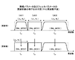
図6は基地局から各移動局に通知される無線パラメータ及びフィルタパラメータの更新前後の様子を示す。更新前の時点で第1移動局UE1には無線パラメータ(BW1,MCS3)及びフィルタパラメータ(α3,N3)が通知され、更新後の時点では無線パラメータ(BW1,MCS1)及びフィルタパラメータ(α1,N1)が通知される。その結果更新後にフィルタの振幅特性が大きく変化している。第2,3移動局UE2,UE3に関しては更新前後でパラメータの内容は不変である。図6に示される例では、無線パラメータ及びフィルタパラメータの更新前後で、送信帯域幅に変更がなければ、中心周波数fc1,fc2,fc3は不変に維持される。従ってパラメータ更新時のフィルタ調整が簡易になる。 FIG. 6 shows the state before and after the update of the radio parameters and filter parameters notified from the base station to each mobile station. The radio parameters (BW1, MCS3) and the filter parameters (α 3 , N 3 ) are notified to the first mobile station UE1 before the update, and the radio parameters (BW1, MCS1) and the filter parameters (α 1 , N 1 ) is notified. As a result, the filter amplitude characteristics have changed greatly after the update. Regarding the second and third mobile stations UE2 and UE3, the contents of the parameters are unchanged before and after the update. In the example shown in FIG. 6, the center frequencies f c1 , f c2 , and f c3 are maintained unchanged if there is no change in the transmission bandwidth before and after the update of the radio parameters and the filter parameters. Therefore, filter adjustment at the time of parameter update is simplified.
図7も基地局から各移動局に通知される無線パラメータ及びフィルタパラメータの更新前後の様子を示す。更新前の時点で第1移動局UE1にはフィルタパラメータ(α3,N3)が通知され、更新後の時点ではフィルタパラメータ(α4,N4)が通知される。その結果更新後にフィルタの振幅特性が変化している。無線パラメータも更新されてよいが、図示の簡明化のため無線パラメータは省略されている。更新前の時点で第2移動局UE2にはフィルタパラメータ(α1,N1)が通知され、更新後の時点ではフィルタパラメータ(α2,N2)が通知される。その結果更新後にフィルタの振幅特性が変化している。更新前の時点で第3移動局UE3にはフィルタパラメータ(α5,N5)が通知され、更新後の時点ではフィルタパラメータ(α6,N6)が通知される。その結果更新後にフィルタの振幅特性が変化している。図7に示される例では、無線パラメータ及びフィルタパラメータの更新前後で、中心周波数fc1,fc2,fc3は変化してよい。従ってパラメータ更新時のフィルタ調整はその分だけ複雑化するが、帯域の利用効率を高めることができる。 FIG. 7 also shows the state before and after the update of the radio parameters and filter parameters notified from the base station to each mobile station. The filter parameter (α 3 , N 3 ) is notified to the first mobile station UE1 before the update, and the filter parameter (α 4 , N 4 ) is notified at the time after the update. As a result, the filter amplitude characteristics have changed after the update. The radio parameters may also be updated, but the radio parameters are omitted for simplicity of illustration. The filter parameter (α 1 , N 1 ) is notified to the second mobile station UE2 before the update, and the filter parameter (α 2 , N 2 ) is notified at the time after the update. As a result, the filter amplitude characteristics have changed after the update. The filter parameter (α 5 , N 5 ) is notified to the third mobile station UE3 before the update, and the filter parameter (α 6 , N 6 ) is notified at the time after the update. As a result, the filter amplitude characteristics have changed after the update. In the example illustrated in FIG. 7, the center frequencies f c1 , f c2 , and f c3 may change before and after the update of the radio parameter and the filter parameter. Therefore, the filter adjustment at the time of parameter update is complicated accordingly, but the bandwidth utilization efficiency can be improved.
UE 移動局
BS 基地局
α ロールオフ率
UE mobile station BS base station α roll-off rate
Claims (10)
システム周波数帯域の全部又は一部を使用する移動局と通信を行う手段と、
上りリンクの帯域幅、変調方式及びチャネル符号化率を含む無線パラメータと帯域制限フィルタのロールオフ率を少なくとも含むフィルタパラメータとの対応関係を記憶する記憶手段と、
上りリンクのチャネル状態に応じて前記対応関係から移動局毎に無線パラメータ及びフィルタパラメータを決定する決定手段と、
を有し、前記決定手段で決定された無線パラメータ及びフィルタパラメータが移動局に通知される
ことを特徴とする基地局。 A base station used in a mobile communication system using a single carrier scheme for uplink,
Means for communicating with a mobile station using all or part of the system frequency band;
Storage means for storing a correspondence relationship between radio parameters including uplink bandwidth, modulation scheme and channel coding rate, and filter parameters including at least a roll-off rate of a band-limiting filter;
Determining means for determining a radio parameter and a filter parameter for each mobile station from the correspondence according to an uplink channel state;
The base station is characterized in that the mobile station is notified of the radio parameter and the filter parameter determined by the determining means.
ことを特徴とする請求項1記載の基地局。 The base station according to claim 1, wherein the correspondence relationship associates a radio parameter having a higher bit rate with a smaller roll-off rate.
ことを特徴とする請求項1記載の基地局。 The base station according to claim 1, wherein the correspondence relationship associates a radio parameter having a lower bit rate with a larger roll-off rate.
ことを特徴とする請求項1記載の基地局。 The base station according to claim 1, wherein the correspondence relationship associates a wider bandwidth with a larger roll-off rate.
ことを特徴とする請求項1記載の基地局。 The base station according to claim 1, wherein the correspondence relationship associates a narrower bandwidth with a smaller roll-off rate.
ことを特徴とする請求項1記載の基地局。 The bandwidth center frequency is maintained unchanged when both the modulation scheme and / or the channel coding rate are changed when uplink radio resource allocation is updated. The listed base station.
ことを特徴とする請求項1記載の基地局。 The bandwidth center frequency is allowed to be changed when both or one of the modulation scheme and the channel coding rate is changed when the uplink radio resource allocation content is updated. The listed base station.
システム周波数帯域の全部又は一部を使用して基地局と通信を行う手段と、
上りリンクの帯域幅、変調方式及びチャネル符号化率を含む無線パラメータと帯域制限フィルタのロールオフ率を少なくとも含むフィルタパラメータとの対応関係を記憶する記憶手段と、
基地局からの制御信号及び前記対応関係から上りリンクの無線パラメータ及びフィルタパラメータを決定する決定手段と、
を有することを特徴とする移動局。 A mobile station used in a mobile communication system using a single carrier scheme for uplink,
Means for communicating with the base station using all or part of the system frequency band;
Storage means for storing a correspondence relationship between radio parameters including uplink bandwidth, modulation scheme and channel coding rate, and filter parameters including at least a roll-off rate of a band-limiting filter;
Determining means for determining an uplink radio parameter and a filter parameter from the control signal from the base station and the correspondence relationship;
A mobile station characterized by comprising:
上りリンクの帯域幅、変調方式及びチャネル符号化率を含む無線パラメータと帯域制限フィルタのロールオフ率を少なくとも含むフィルタパラメータとの対応関係を記憶し、
上りリンクのチャネル状態に応じて前記対応関係から移動局毎に無線パラメータ及びフィルタパラメータを決定し、
決定された無線パラメータ及びフィルタパラメータを、システム周波数帯域の全部又は一部を使用する移動局に通知する
ことを特徴とする方法。 A method used in a base station of a mobile communication system using a single carrier scheme for uplink,
Storing a correspondence relationship between radio parameters including uplink bandwidth, modulation scheme and channel coding rate, and filter parameters including at least a roll-off rate of a band limiting filter;
Radio parameters and filter parameters are determined for each mobile station from the correspondence according to the uplink channel state,
The determined radio parameter and filter parameter are notified to a mobile station that uses all or part of the system frequency band.
上りリンクの帯域幅、変調方式及びチャネル符号化率を含む無線パラメータと帯域制限フィルタのロールオフ率を少なくとも含むフィルタパラメータとの対応関係を記憶し、
基地局からの制御信号を受信し、
前記制御信号及び前記対応関係から上りリンクの無線パラメータ及びフィルタパラメータを決定し、
システム周波数帯域の全部又は一部を使用して基地局に信号を送信する
ことを特徴とする方法。 A method used in a mobile station of a mobile communication system using a single carrier scheme for uplink,
Storing a correspondence relationship between radio parameters including uplink bandwidth, modulation scheme and channel coding rate, and filter parameters including at least a roll-off rate of a band limiting filter;
Receive control signals from the base station,
An uplink radio parameter and a filter parameter are determined from the control signal and the correspondence relationship;
A method of transmitting a signal to a base station using all or part of a system frequency band.
Priority Applications (9)
| Application Number | Priority Date | Filing Date | Title |
|---|---|---|---|
| JP2006077822A JP4732935B2 (en) | 2006-03-20 | 2006-03-20 | Base station, mobile station and method |
| US12/293,627 US8526511B2 (en) | 2006-03-20 | 2007-03-19 | Base station, mobile station and method |
| PCT/JP2007/055578 WO2007111187A1 (en) | 2006-03-20 | 2007-03-19 | Base station, mobile station, and method |
| EP20070739021 EP1998586B1 (en) | 2006-03-20 | 2007-03-19 | Base station, mobile station, and method |
| KR1020087025013A KR20080113060A (en) | 2006-03-20 | 2007-03-19 | Base station, mobile station, and method |
| CN2007800164372A CN101438611B (en) | 2006-03-20 | 2007-03-19 | Base station, mobile station, and method |
| RU2008141086/09A RU2420034C2 (en) | 2006-03-20 | 2007-03-19 | Basic station, mobile station and method of communication |
| BRPI0709031-5A BRPI0709031A2 (en) | 2006-03-20 | 2007-03-19 | base station, mobile station and method |
| TW096109558A TW200746692A (en) | 2006-03-20 | 2007-03-20 | Base station, mobile station, and method |
Applications Claiming Priority (1)
| Application Number | Priority Date | Filing Date | Title |
|---|---|---|---|
| JP2006077822A JP4732935B2 (en) | 2006-03-20 | 2006-03-20 | Base station, mobile station and method |
Publications (2)
| Publication Number | Publication Date |
|---|---|
| JP2007258843A JP2007258843A (en) | 2007-10-04 |
| JP4732935B2 true JP4732935B2 (en) | 2011-07-27 |
Family
ID=38541107
Family Applications (1)
| Application Number | Title | Priority Date | Filing Date |
|---|---|---|---|
| JP2006077822A Expired - Fee Related JP4732935B2 (en) | 2006-03-20 | 2006-03-20 | Base station, mobile station and method |
Country Status (9)
| Country | Link |
|---|---|
| US (1) | US8526511B2 (en) |
| EP (1) | EP1998586B1 (en) |
| JP (1) | JP4732935B2 (en) |
| KR (1) | KR20080113060A (en) |
| CN (1) | CN101438611B (en) |
| BR (1) | BRPI0709031A2 (en) |
| RU (1) | RU2420034C2 (en) |
| TW (1) | TW200746692A (en) |
| WO (1) | WO2007111187A1 (en) |
Families Citing this family (28)
| Publication number | Priority date | Publication date | Assignee | Title |
|---|---|---|---|---|
| JP5080330B2 (en) | 2008-03-28 | 2012-11-21 | 株式会社エヌ・ティ・ティ・ドコモ | User apparatus, base station apparatus, and communication control method |
| JP5213586B2 (en) * | 2008-08-25 | 2013-06-19 | 株式会社エヌ・ティ・ティ・ドコモ | User apparatus, base station apparatus, and communication control method |
| JP2010130261A (en) * | 2008-11-26 | 2010-06-10 | Kyocera Corp | Communication device, and method of determining modulation method |
| KR101640624B1 (en) * | 2009-01-30 | 2016-07-19 | 삼성전자주식회사 | Method and apparatus of control signaling for transmissions over continuous and non-contiguous frequency bands |
| US9882624B2 (en) | 2010-09-29 | 2018-01-30 | Qualcomm, Incorporated | Systems and methods for communication of channel state information |
| US9831983B2 (en) | 2010-09-29 | 2017-11-28 | Qualcomm Incorporated | Systems, methods and apparatus for determining control field and modulation coding scheme information |
| US9374193B2 (en) * | 2010-09-29 | 2016-06-21 | Qualcomm Incorporated | Systems and methods for communication of channel state information |
| US9602298B2 (en) | 2010-09-29 | 2017-03-21 | Qualcomm Incorporated | Methods and apparatuses for determining a type of control field |
| US9813135B2 (en) | 2010-09-29 | 2017-11-07 | Qualcomm, Incorporated | Systems and methods for communication of channel state information |
| US10090982B2 (en) | 2010-09-29 | 2018-10-02 | Qualcomm Incorporated | Systems and methods for communication of channel state information |
| US9077498B2 (en) | 2010-09-29 | 2015-07-07 | Qualcomm Incorporated | Systems and methods for communication of channel state information |
| US9806848B2 (en) | 2010-09-29 | 2017-10-31 | Qualcomm Incorporated | Systems, methods and apparatus for determining control field and modulation coding scheme information |
| CN102143503B (en) * | 2010-12-17 | 2014-08-13 | 华为终端有限公司 | Method, device and system for configuring bandwidth |
| US9692550B2 (en) | 2012-11-29 | 2017-06-27 | Huawei Technologies Co., Ltd. | Systems and methods for waveform selection and adaptation |
| US8873655B2 (en) * | 2013-01-10 | 2014-10-28 | Intel Corporation | Sending information at a band edge within an orthogonal frequency-division multiplexing (OFDM) symbol |
| SG11201805360RA (en) * | 2016-01-26 | 2018-07-30 | Sony Corp | Apparatus and method |
| US10158555B2 (en) | 2016-09-29 | 2018-12-18 | At&T Intellectual Property I, L.P. | Facilitation of route optimization for a 5G network or other next generation network |
| US10644924B2 (en) | 2016-09-29 | 2020-05-05 | At&T Intellectual Property I, L.P. | Facilitating a two-stage downlink control channel in a wireless communication system |
| US10206232B2 (en) | 2016-09-29 | 2019-02-12 | At&T Intellectual Property I, L.P. | Initial access and radio resource management for integrated access and backhaul (IAB) wireless networks |
| US10602507B2 (en) * | 2016-09-29 | 2020-03-24 | At&T Intellectual Property I, L.P. | Facilitating uplink communication waveform selection |
| US10171214B2 (en) | 2016-09-29 | 2019-01-01 | At&T Intellectual Property I, L.P. | Channel state information framework design for 5G multiple input multiple output transmissions |
| US10355813B2 (en) | 2017-02-14 | 2019-07-16 | At&T Intellectual Property I, L.P. | Link adaptation on downlink control channel in a wireless communications system |
| CN110710174A (en) * | 2017-04-06 | 2020-01-17 | 中兴通讯股份有限公司 | Method and apparatus for wireless communication waveform generation |
| US10660056B2 (en) * | 2017-09-08 | 2020-05-19 | Qualcomm Incorporated | Techniques for timing control with filtering in orthogonal frequency division multiplexing-based systems |
| CN109510789A (en) * | 2017-09-14 | 2019-03-22 | 晨星半导体股份有限公司 | Roll-off parameter judgment method and module |
| WO2019134085A1 (en) * | 2018-01-04 | 2019-07-11 | Oppo广东移动通信有限公司 | Data transmission method, terminal device, network device, and computer storage medium |
| CN111586898B (en) * | 2020-05-27 | 2022-12-13 | 中科信创技术有限公司 | Assembled mobile communication base station |
| US20230028791A1 (en) * | 2021-07-22 | 2023-01-26 | Qualcomm Incorporated | Dynamic shaping filter indications |
Family Cites Families (15)
| Publication number | Priority date | Publication date | Assignee | Title |
|---|---|---|---|---|
| JP3343573B2 (en) * | 2000-01-04 | 2002-11-11 | 独立行政法人通信総合研究所 | Radio equipment with variable modulation / demodulation characteristics |
| US7050419B2 (en) * | 2001-02-23 | 2006-05-23 | Terayon Communicaion Systems, Inc. | Head end receiver for digital data delivery systems using mixed mode SCDMA and TDMA multiplexing |
| JP3660278B2 (en) * | 2001-07-13 | 2005-06-15 | 松下電器産業株式会社 | Base station apparatus, mobile station apparatus, radio communication system, and radio communication method |
| WO2003015443A1 (en) * | 2001-08-01 | 2003-02-20 | Mitsubishi Denki Kabushiki Kaisha | Mobile communication system, mobile communication method, base station, and mobile station |
| US20030125040A1 (en) * | 2001-11-06 | 2003-07-03 | Walton Jay R. | Multiple-access multiple-input multiple-output (MIMO) communication system |
| KR100547882B1 (en) * | 2002-02-26 | 2006-02-01 | 삼성전자주식회사 | Method and apparatus for transmitting and receiving status information of forward channel in mobile telecommunication system supporting selective transmit diversity |
| US7151797B2 (en) * | 2002-05-14 | 2006-12-19 | Limberg Allen Leroy | Adaptive K-factor-improvement filter for receiver of radio signals subject to multipath distortion |
| CN1225854C (en) * | 2002-06-13 | 2005-11-02 | 华为技术有限公司 | Self-adaptive modulating and coding method |
| JP2004312458A (en) * | 2003-04-08 | 2004-11-04 | Matsushita Electric Ind Co Ltd | Base station device and method of adaptive modulation |
| US7342956B2 (en) * | 2003-06-16 | 2008-03-11 | Broadcom Corporation | System and method to extract uplink status flag bits in a cellular wireless network |
| JP4628150B2 (en) * | 2004-03-29 | 2011-02-09 | パナソニック株式会社 | Communication apparatus and communication method |
| JP2006067236A (en) * | 2004-08-26 | 2006-03-09 | Sharp Corp | Radio communication system |
| JP2006077822A (en) | 2004-09-07 | 2006-03-23 | Saginomiya Seisakusho Inc | Pressure-operated valve with switching function |
| US9461736B2 (en) * | 2006-02-21 | 2016-10-04 | Qualcomm Incorporated | Method and apparatus for sub-slot packets in wireless communication |
| US7924775B2 (en) * | 2006-03-17 | 2011-04-12 | Samsung Electronics Co., Ltd. | Apparatus and method for selecting modulation and filter roll-off to meet power and bandwidth requirements |
-
2006
- 2006-03-20 JP JP2006077822A patent/JP4732935B2/en not_active Expired - Fee Related
-
2007
- 2007-03-19 BR BRPI0709031-5A patent/BRPI0709031A2/en not_active IP Right Cessation
- 2007-03-19 WO PCT/JP2007/055578 patent/WO2007111187A1/en active Application Filing
- 2007-03-19 KR KR1020087025013A patent/KR20080113060A/en not_active Application Discontinuation
- 2007-03-19 EP EP20070739021 patent/EP1998586B1/en not_active Not-in-force
- 2007-03-19 US US12/293,627 patent/US8526511B2/en not_active Expired - Fee Related
- 2007-03-19 RU RU2008141086/09A patent/RU2420034C2/en not_active IP Right Cessation
- 2007-03-19 CN CN2007800164372A patent/CN101438611B/en not_active Expired - Fee Related
- 2007-03-20 TW TW096109558A patent/TW200746692A/en unknown
Also Published As
| Publication number | Publication date |
|---|---|
| KR20080113060A (en) | 2008-12-26 |
| CN101438611B (en) | 2011-12-07 |
| WO2007111187A1 (en) | 2007-10-04 |
| EP1998586A4 (en) | 2012-11-28 |
| RU2420034C2 (en) | 2011-05-27 |
| JP2007258843A (en) | 2007-10-04 |
| TW200746692A (en) | 2007-12-16 |
| EP1998586A1 (en) | 2008-12-03 |
| CN101438611A (en) | 2009-05-20 |
| US20100290544A1 (en) | 2010-11-18 |
| RU2008141086A (en) | 2010-04-27 |
| US8526511B2 (en) | 2013-09-03 |
| EP1998586B1 (en) | 2015-04-29 |
| BRPI0709031A2 (en) | 2011-06-21 |
Similar Documents
| Publication | Publication Date | Title |
|---|---|---|
| JP4732935B2 (en) | Base station, mobile station and method | |
| EP2216924A1 (en) | Radio communication system, radio transmission device, radio communication method, and program | |
| JP5297520B2 (en) | Frequency hopping pattern and configuration for sounding reference signal | |
| KR101115215B1 (en) | Superposition coding in a wireless communication system | |
| CA2710535C (en) | Sounding reference signal arrangement | |
| KR100903527B1 (en) | Transmitting data in a wireless network | |
| RU2414057C2 (en) | Dynamic power loss coefficient of power amplifier | |
| JP2006515119A (en) | Waveform generation for adaptive air interface | |
| WO2010018442A2 (en) | System and method of modulation and coding scheme adjustment for a lte shared data channel | |
| US7489943B2 (en) | Scheduling calls in downlink transmissions | |
| EP1821478B1 (en) | Method and system for transmitting data in a communication system | |
| Zhang et al. | Adaptive multiuser radio resource allocation for OFDMA systems | |
| Ohseki et al. | Fast outer-loop link adaptation scheme realizing low-latency transmission in LTE-advanced and future wireless networks | |
| Sun et al. | Multi-user scheduling for OFDM downlink with limited feedback for evolved UTRA | |
| JP5422752B2 (en) | Terminal and its grant processing method | |
| US9007926B2 (en) | Configuration and scheduling of asymmetric carriers on the uplink | |
| Awal et al. | Dynamic cqi resource allocation for ofdma systems | |
| Moiseev et al. | Optimal average number of data block transmissions for the ARQ mechanism in the IEEE 802.16 OFDMA system | |
| AU2012227366B2 (en) | Base station device, mobile terminal device, wireless communication system, and wireless communication method | |
| Thontadharya et al. | Simulation and Emulation Approach for the Performance Evaluation of Adaptive Modulation and Coding Scheme in Mobile WiMAX Network | |
| Huibin et al. | Scheduling and performance of multicarrier TD-SCDMA HSDPA |
Legal Events
| Date | Code | Title | Description |
|---|---|---|---|
| A621 | Written request for application examination |
Free format text: JAPANESE INTERMEDIATE CODE: A621 Effective date: 20090210 |
|
| TRDD | Decision of grant or rejection written | ||
| A01 | Written decision to grant a patent or to grant a registration (utility model) |
Free format text: JAPANESE INTERMEDIATE CODE: A01 Effective date: 20110419 |
|
| A01 | Written decision to grant a patent or to grant a registration (utility model) |
Free format text: JAPANESE INTERMEDIATE CODE: A01 |
|
| A61 | First payment of annual fees (during grant procedure) |
Free format text: JAPANESE INTERMEDIATE CODE: A61 Effective date: 20110421 |
|
| FPAY | Renewal fee payment (event date is renewal date of database) |
Free format text: PAYMENT UNTIL: 20140428 Year of fee payment: 3 |
|
| R150 | Certificate of patent or registration of utility model |
Ref document number: 4732935 Country of ref document: JP Free format text: JAPANESE INTERMEDIATE CODE: R150 Free format text: JAPANESE INTERMEDIATE CODE: R150 |
|
| R250 | Receipt of annual fees |
Free format text: JAPANESE INTERMEDIATE CODE: R250 |
|
| R250 | Receipt of annual fees |
Free format text: JAPANESE INTERMEDIATE CODE: R250 |
|
| R250 | Receipt of annual fees |
Free format text: JAPANESE INTERMEDIATE CODE: R250 |
|
| R250 | Receipt of annual fees |
Free format text: JAPANESE INTERMEDIATE CODE: R250 |
|
| R250 | Receipt of annual fees |
Free format text: JAPANESE INTERMEDIATE CODE: R250 |
|
| LAPS | Cancellation because of no payment of annual fees |