JP4732315B2 - Image processing apparatus and method - Google Patents
Image processing apparatus and method Download PDFInfo
- Publication number
- JP4732315B2 JP4732315B2 JP2006328525A JP2006328525A JP4732315B2 JP 4732315 B2 JP4732315 B2 JP 4732315B2 JP 2006328525 A JP2006328525 A JP 2006328525A JP 2006328525 A JP2006328525 A JP 2006328525A JP 4732315 B2 JP4732315 B2 JP 4732315B2
- Authority
- JP
- Japan
- Prior art keywords
- paper fingerprint
- fingerprint information
- paper
- image
- area
- Prior art date
- Legal status (The legal status is an assumption and is not a legal conclusion. Google has not performed a legal analysis and makes no representation as to the accuracy of the status listed.)
- Expired - Fee Related
Links
- 238000012545 processing Methods 0.000 title claims description 114
- 238000000034 method Methods 0.000 title description 134
- 238000003672 processing method Methods 0.000 claims description 7
- 230000006870 function Effects 0.000 description 20
- WBMKMLWMIQUJDP-STHHAXOLSA-N (4R,4aS,7aR,12bS)-4a,9-dihydroxy-3-prop-2-ynyl-2,4,5,6,7a,13-hexahydro-1H-4,12-methanobenzofuro[3,2-e]isoquinolin-7-one hydrochloride Chemical compound Cl.Oc1ccc2C[C@H]3N(CC#C)CC[C@@]45[C@@H](Oc1c24)C(=O)CC[C@@]35O WBMKMLWMIQUJDP-STHHAXOLSA-N 0.000 description 18
- 238000010586 diagram Methods 0.000 description 17
- 238000006243 chemical reaction Methods 0.000 description 14
- 238000001514 detection method Methods 0.000 description 12
- 238000012795 verification Methods 0.000 description 12
- 238000003705 background correction Methods 0.000 description 10
- 238000012937 correction Methods 0.000 description 10
- 238000004364 calculation method Methods 0.000 description 8
- 230000015572 biosynthetic process Effects 0.000 description 7
- 238000001444 catalytic combustion detection Methods 0.000 description 7
- 239000000835 fiber Substances 0.000 description 7
- 238000007689 inspection Methods 0.000 description 7
- 230000005540 biological transmission Effects 0.000 description 6
- 239000007787 solid Substances 0.000 description 6
- 230000006835 compression Effects 0.000 description 5
- 238000007906 compression Methods 0.000 description 5
- 238000003786 synthesis reaction Methods 0.000 description 5
- 230000006837 decompression Effects 0.000 description 4
- 230000000694 effects Effects 0.000 description 4
- 230000035945 sensitivity Effects 0.000 description 4
- 239000002131 composite material Substances 0.000 description 3
- 239000000428 dust Substances 0.000 description 3
- 239000000463 material Substances 0.000 description 3
- 239000011159 matrix material Substances 0.000 description 3
- 230000007423 decrease Effects 0.000 description 2
- 230000000994 depressogenic effect Effects 0.000 description 2
- 239000002421 finishing Substances 0.000 description 2
- 238000011835 investigation Methods 0.000 description 2
- 230000000873 masking effect Effects 0.000 description 2
- 230000002093 peripheral effect Effects 0.000 description 2
- 230000002265 prevention Effects 0.000 description 2
- 238000000926 separation method Methods 0.000 description 2
- 239000003086 colorant Substances 0.000 description 1
- 238000013524 data verification Methods 0.000 description 1
- 230000003247 decreasing effect Effects 0.000 description 1
- 230000000881 depressing effect Effects 0.000 description 1
- 238000009792 diffusion process Methods 0.000 description 1
- 238000005516 engineering process Methods 0.000 description 1
- 239000000284 extract Substances 0.000 description 1
- 238000000605 extraction Methods 0.000 description 1
- 239000011521 glass Substances 0.000 description 1
- 238000009499 grossing Methods 0.000 description 1
- 230000002452 interceptive effect Effects 0.000 description 1
- 238000010606 normalization Methods 0.000 description 1
- 230000003287 optical effect Effects 0.000 description 1
- 238000007781 pre-processing Methods 0.000 description 1
- 238000009877 rendering Methods 0.000 description 1
- 238000005070 sampling Methods 0.000 description 1
- 238000001308 synthesis method Methods 0.000 description 1
Images


Classifications
-
- G—PHYSICS
- G06—COMPUTING; CALCULATING OR COUNTING
- G06V—IMAGE OR VIDEO RECOGNITION OR UNDERSTANDING
- G06V30/00—Character recognition; Recognising digital ink; Document-oriented image-based pattern recognition
- G06V30/40—Document-oriented image-based pattern recognition
- G06V30/41—Analysis of document content
-
- G—PHYSICS
- G06—COMPUTING; CALCULATING OR COUNTING
- G06V—IMAGE OR VIDEO RECOGNITION OR UNDERSTANDING
- G06V20/00—Scenes; Scene-specific elements
- G06V20/80—Recognising image objects characterised by unique random patterns
-
- G—PHYSICS
- G07—CHECKING-DEVICES
- G07D—HANDLING OF COINS OR VALUABLE PAPERS, e.g. TESTING, SORTING BY DENOMINATIONS, COUNTING, DISPENSING, CHANGING OR DEPOSITING
- G07D7/00—Testing specially adapted to determine the identity or genuineness of valuable papers or for segregating those which are unacceptable, e.g. banknotes that are alien to a currency
- G07D7/20—Testing patterns thereon
- G07D7/202—Testing patterns thereon using pattern matching
- G07D7/2033—Matching unique patterns, i.e. patterns that are unique to each individual paper
-
- H—ELECTRICITY
- H04—ELECTRIC COMMUNICATION TECHNIQUE
- H04N—PICTORIAL COMMUNICATION, e.g. TELEVISION
- H04N1/00—Scanning, transmission or reproduction of documents or the like, e.g. facsimile transmission; Details thereof
- H04N1/0035—User-machine interface; Control console
- H04N1/00405—Output means
- H04N1/00408—Display of information to the user, e.g. menus
- H04N1/00411—Display of information to the user, e.g. menus the display also being used for user input, e.g. touch screen
-
- H—ELECTRICITY
- H04—ELECTRIC COMMUNICATION TECHNIQUE
- H04N—PICTORIAL COMMUNICATION, e.g. TELEVISION
- H04N1/00—Scanning, transmission or reproduction of documents or the like, e.g. facsimile transmission; Details thereof
- H04N1/0035—User-machine interface; Control console
- H04N1/00405—Output means
- H04N1/0048—Indicating an illegal or impossible operation or selection to the user
-
- H—ELECTRICITY
- H04—ELECTRIC COMMUNICATION TECHNIQUE
- H04N—PICTORIAL COMMUNICATION, e.g. TELEVISION
- H04N1/00—Scanning, transmission or reproduction of documents or the like, e.g. facsimile transmission; Details thereof
- H04N1/32—Circuits or arrangements for control or supervision between transmitter and receiver or between image input and image output device, e.g. between a still-image camera and its memory or between a still-image camera and a printer device
- H04N1/32101—Display, printing, storage or transmission of additional information, e.g. ID code, date and time or title
-
- H—ELECTRICITY
- H04—ELECTRIC COMMUNICATION TECHNIQUE
- H04N—PICTORIAL COMMUNICATION, e.g. TELEVISION
- H04N2201/00—Indexing scheme relating to scanning, transmission or reproduction of documents or the like, and to details thereof
- H04N2201/32—Circuits or arrangements for control or supervision between transmitter and receiver or between image input and image output device, e.g. between a still-image camera and its memory or between a still-image camera and a printer device
- H04N2201/3201—Display, printing, storage or transmission of additional information, e.g. ID code, date and time or title
- H04N2201/3225—Display, printing, storage or transmission of additional information, e.g. ID code, date and time or title of data relating to an image, a page or a document
- H04N2201/3233—Display, printing, storage or transmission of additional information, e.g. ID code, date and time or title of data relating to an image, a page or a document of authentication information, e.g. digital signature, watermark
- H04N2201/3235—Checking or certification of the authentication information, e.g. by comparison with data stored independently
-
- H—ELECTRICITY
- H04—ELECTRIC COMMUNICATION TECHNIQUE
- H04N—PICTORIAL COMMUNICATION, e.g. TELEVISION
- H04N2201/00—Indexing scheme relating to scanning, transmission or reproduction of documents or the like, and to details thereof
- H04N2201/32—Circuits or arrangements for control or supervision between transmitter and receiver or between image input and image output device, e.g. between a still-image camera and its memory or between a still-image camera and a printer device
- H04N2201/3201—Display, printing, storage or transmission of additional information, e.g. ID code, date and time or title
- H04N2201/3225—Display, printing, storage or transmission of additional information, e.g. ID code, date and time or title of data relating to an image, a page or a document
- H04N2201/3233—Display, printing, storage or transmission of additional information, e.g. ID code, date and time or title of data relating to an image, a page or a document of authentication information, e.g. digital signature, watermark
- H04N2201/3236—Details of authentication information generation
Description
本発明は、画像処理装置及び方法に関する。より詳細には、紙の繊維の情報、所謂紙指紋(以下では、紙指紋のことを紙紋とも称する)情報を取り扱うことができる画像処理装置、画像処理方法、プログラム及び記録媒体に関する。 The present invention relates to an image processing apparatus and method. More specifically, the present invention relates to an image processing apparatus, an image processing method, a program, and a recording medium capable of handling information on paper fibers, so-called paper fingerprint (hereinafter, paper fingerprint is also referred to as paper print) information.
従来、デジタル複合機を用いて文書の偽造コピーの追跡調査を目的に、画像データに機種番号などの補助データを埋め込む処理が存在する。また、その補助データ埋め込み処理において、第三者が印刷された画像から補助データを容易に発見して、解読することを防ぐために、埋め込み処理時に発見しにくい場所に埋め込む技術が存在する(たとえば、特許文献1参照)。 Conventionally, there is a process of embedding auxiliary data such as a model number in image data for the purpose of tracking investigation of a counterfeit copy of a document using a digital multifunction peripheral. In addition, in the auxiliary data embedding process, there is a technique of embedding in a place that is difficult to find at the time of the embedding process in order to prevent the third party from easily discovering and decoding the auxiliary data from the printed image (for example, Patent Document 1).
また、書類の原本性保証を目的に、画像データ上のイメージ情報に含まれる再現不能な乱れ部の特徴を抽出し、その抽出したデータと読み取り時に抽出した乱れ部の特徴とを比較する。そして、その比較結果に基づいて読み取り原稿が原本であるかどうかの判定を行う技術が存在する(たとえば、特許文献2参照)。 Further, for the purpose of guaranteeing the originality of the document, the feature of the unreproducible disorder portion included in the image information on the image data is extracted, and the extracted data is compared with the feature of the disorder portion extracted at the time of reading. There is a technique for determining whether a read original is an original based on the comparison result (see, for example, Patent Document 2).
また、紙の繊維情報を読み取る技術として、用紙に付加されたマークを基準として繊維情報を読み取り、この繊維情報を所定のパターンに変換して印字する技術がある(たとえば、特許文献3参照)。 Further, as a technique for reading fiber information of paper, there is a technique of reading fiber information on the basis of a mark added to the paper, converting the fiber information into a predetermined pattern, and printing (see, for example, Patent Document 3).
さらに、紙に埋め込む付加データの面積を変化する技術として、画像の近傍の平均濃度値に応じて面積を大きくし、さらに付加データの値により形状パターンを変え、そしてこのパターンを画像に埋め込む技術が存在する(たとえば、特許文献4参照)。 Furthermore, as a technique for changing the area of the additional data embedded in the paper, there is a technique for increasing the area according to the average density value in the vicinity of the image, changing the shape pattern according to the value of the additional data, and embedding this pattern in the image. Exists (for example, see Patent Document 4).
しかしながら、この特許文献1開示の技術は、偽造コピーの追跡調査のための補助データを用紙の画像部に埋め込み、発見しにくくするものである。この技術の場合、偽造を行いにくくする効果はあるが、切り貼りなどを行い画像部に埋め込まれた補助データを隠してしまうと、偽造が可能になってしまう課題があった。
However, the technology disclosed in
また、特許文献2開示の技術は、画像データ上の再現不能な乱れ部特徴を用いて原本性保証を行う技術である。この技術の場合、乱れ部とは用紙に載せるトナーの飛び散りや、線エッジのシャギー部などを指しており、用紙に対して描画(付加)した情報を元に原本性を保証するものである。したがって、印字時に期待する乱れ部が生成されていない場合などは、原本性保証が行えなくなってしまう課題があった。
The technique disclosed in
また、特許文献3開示の技術は、用紙に付加されたマークを基準にして読み取り領域を決める技術であるが、この領域が紙指紋領域として適切な領域であるかどうか考慮していない。そのため、べた黒のような紙指紋を正確に読み取れない領域を読み取り領域とし決めてしまうという課題があった。
The technique disclosed in
また、特許文献4開示の技術は、所定の領域の平均濃度を求めて付加データを埋め込む面積を決める技術であるが、面積を変化した後の照合率は考慮していない。そのため、所定の領域の付近にべた黒のような照合率の悪い領域が広がっている場合、平均濃度に応じて面積を変化しても紙指紋を正確に読み取れない領域に付加データを埋め込んでしまうという課題があった。
The technique disclosed in
本発明は、このような課題に鑑みてなされたもので、その目的とするところは、マッチング精度やセキュリティを考慮した位置の紙指紋を登録することが可能な画像処理装置及び方法を提供することにある。 The present invention has been made in view of such problems, and an object thereof is to provide an image processing apparatus and method capable of registering a paper fingerprint at a position in consideration of matching accuracy and security. It is in.
本願発明の画像処理装置は、紙をスキャンして、得られた画像データから紙指紋情報を取得する紙指紋情報取得手段と、紙指紋情報取得手段において取得され、記憶された紙指紋情報と他の紙指紋情報との類似度を閾値と比較することで、記憶された紙指紋情報の照合を行う紙指紋情報照合手段とを備え、紙指紋情報の取得領域として、画像領域が一部含まれている箇所の紙指紋情報が前記記憶された紙指紋情報となることを特徴とする。 The image processing apparatus according to the present invention includes a paper fingerprint information acquisition unit that scans paper and acquires paper fingerprint information from the obtained image data, and the paper fingerprint information acquired and stored in the paper fingerprint information acquisition unit. Paper fingerprint information collation means for collating stored paper fingerprint information by comparing the similarity with the paper fingerprint information of the image to a threshold value, and a part of the image area is included as an acquisition area of the paper fingerprint information. The paper fingerprint information at the location is the stored paper fingerprint information.
本発明の画像処理方法は、紙をスキャンして、得られた画像データから紙指紋情報を取得する紙指紋情報取得ステップと、紙指紋情報取得ステップにおいて取得され、記憶された紙指紋情報と他の紙指紋情報との類似度を閾値と比較することで、記憶された紙指紋情報の照合を行う紙指紋情報照合ステップとを備え、紙指紋情報の取得領域として、画像領域が一部含まれている箇所の紙指紋情報が記憶された紙指紋情報となることを特徴とする。 The image processing method of the present invention includes a paper fingerprint information acquisition step of acquiring paper fingerprint information from the obtained image data by scanning paper, and the paper fingerprint information acquired and stored in the paper fingerprint information acquisition step. A paper fingerprint information collation step for collating stored paper fingerprint information by comparing the degree of similarity with the paper fingerprint information with a threshold, and a part of the image area is included as an acquisition area of the paper fingerprint information. The paper fingerprint information of the location is the stored paper fingerprint information.
本願発明の画像処理装置は、対象紙の紙指紋を読み取り取得する紙指紋情報取得手段と、対象紙に含まれる複数の領域のうち画像が一部含まれる領域を、紙指紋情報取得手段により紙指紋を取得し、記憶するための紙指紋領域と判定する領域判定手段と、領域判定手段により判定された紙指紋領域の紙指紋情報を紙指紋情報取得手段により読み取って、対象紙に対する紙指紋情報として登録する紙指紋登録手段とを備えたことを特徴とする。 The image processing apparatus according to the present invention includes a paper fingerprint information acquisition unit that reads and acquires a paper fingerprint of a target paper, and a paper fingerprint information acquisition unit that extracts a region including a part of an image from a plurality of regions included in the target paper. An area determination unit that determines a paper fingerprint area for acquiring and storing a fingerprint, and the paper fingerprint information of the paper fingerprint area determined by the area determination unit is read by the paper fingerprint information acquisition unit, and the paper fingerprint information for the target paper And a paper fingerprint registering means for registering as follows.
本発明の画像処理方法は、領域判定手段によって対象紙に含まれる領域のうち画像が一部含まれる領域を、紙指紋を取得し記憶するための紙指紋領域と、判定する領域判定ステップと、紙指紋情報取得手段によって、領域判定ステップにおいて判定された紙指紋領域の紙指紋情報を読み取る紙指紋情報取得ステップと、紙指紋情報取得ステップにおいて読み取られた紙指紋情報を紙指紋登録手段によって対象紙に対する紙指紋情報として登録する紙指紋登録ステップとを備えたことを特徴とする。
The image processing method of the present invention includes a region determination step for determining, as a paper fingerprint region for acquiring and storing a paper fingerprint, a region including a part of the image included in the target paper by the region determination unit, A paper fingerprint information acquisition step for reading the paper fingerprint information of the paper fingerprint area determined in the area determination step by the paper fingerprint information acquisition means; and the paper fingerprint information read in the paper fingerprint information acquisition step by the paper fingerprint registration means. And a paper fingerprint registration step of registering as paper fingerprint information for.
以上の構成により、(1)認識精度の高い領域の紙指紋を登録することが可能となる。また、(2)必要な情報が存在する部分の紙指紋を登録することが可能となる(そこを覆い隠された場合、必要な情報も読み取れない)。 With the above configuration, (1) it is possible to register a paper fingerprint in a region with high recognition accuracy. In addition, (2) it is possible to register a paper fingerprint of a portion where necessary information exists (if the information is hidden, necessary information cannot be read).
本発明によれば、紙本来の特性である紙指紋を用いて原本性保証・複製防止を行う際に、ユーザによるセキュリティに対する妨害を防ぐことが可能になる効果を奏する。また、印字の多い紙(非画像領域の少ない紙)においても、照合率の高い紙指紋領域を見つけられるため、より多くの紙において紙指紋を設定・登録することが可能となる効果を奏する。 According to the present invention, there is an effect that it is possible to prevent interference with security by a user when performing originality assurance / duplication prevention using a paper fingerprint, which is an original characteristic of paper. In addition, a paper fingerprint region with a high collation rate can be found even on paper with a lot of printing (paper with a small non-image area), so that it is possible to set and register paper fingerprints on more paper.
以下、図面を参照して本発明を適用できる実施形態を詳細に説明する。尚、本明細書で参照される各図面において同様の機能を有する箇所には同一の符号を付している。 Embodiments to which the present invention can be applied will be described below in detail with reference to the drawings. In the drawings referred to in this specification, portions having the same function are denoted by the same reference numerals.
[実施形態1]
<印刷システム(図1)>
実施形態1について図面を参照して詳細に説明する。図1は本発明の実施形態に係る印刷システムの構成を示すブロック図である。このシステムではホストコンピュータ40及び3台の画像形成装置(10,20,30)がLAN50に接続されているが、本実施例における印刷システムにおいては、これらの接続数に限られることはない。また、本実施形態では接続方法としてLANを適用しているが、これに限られることはない。例えば、WAN(公衆回線)などの任意のネットワーク、USBなどのシリアル伝送方式、セントロニクスやSCSIなどのパラレル伝送方式なども適用可能である。
[Embodiment 1]
<Printing system (Fig. 1)>
ホストコンピュータ(以下、PCと称する)40はパーソナルコンピュータの機能を有している。このPC40はLAN50やWANを介してFTPやSMBプロトコルを用いファイルを送受信したり電子メールを送受信したりすることができる。またPC40から画像形成装置10、20、30に対して、プリンタドライバを介した印字命令を行うことが可能となっている。
A host computer (hereinafter referred to as a PC) 40 has a function of a personal computer. The PC 40 can send and receive files and send and receive e-mails using the FTP and SMB protocols via the
画像形成装置10と20は同じ構成を有する装置である。画像形成装置30はプリント機能のみの画像形成装置であり、画像形成装置10や20が有するスキャナ部を有していない。以下では、説明の簡単のために、画像形成装置10、20のうちの画像形成装置10に注目して、その構成を詳細に説明する。
The
画像形成装置10は、画像入力デバイスであるスキャナ部13、画像出力デバイスであるプリンタ部14、コントローラ(Controller Unit)11、ユーザインターフェース(UI)である操作部12から構成される。コントローラ11は、画像形成装置10全体の動作制御を司る。
The
<画像形成装置10(図2)>
画像形成装置10の外観を図2に示す。スキャナ部13は、複数のCCDを有している。この各CCDの感度が夫々異なっていると、たとえ原稿上の各画素の濃度が同じであったとしても、各画素が夫々違う濃度であると認識されてしまう。そのため、スキャナ部では、最初に白板(一様に白い板)を露光走査し、露光走査して得られた反射光の量を電気信号に変換してコントローラ11に出力している。なお、後述するように、コントローラ11内のシェーディング補正部500は、各CCDから得られた電気信号を元に、各CCDの感度の違いを認識している。そして、この認識された感度の違いを利用して、原稿上の画像をスキャンして得られた電気信号の値を補正している。さらに、シェーディング補正部500は、後述するコントローラ11内のCPU301からゲイン調整の情報を受取ると、当該情報に応じたゲイン調整を行う。ゲイン調整は、原稿を露光走査して得られた電気信号の値を、どのように0〜255の輝度信号値に割り付けるかを調整するために用いられる。このゲイン調整により、原稿を露光走査して得られた電気信号の値を高い輝度信号値に変換したり、低い輝度信号値に変換したりすることができるようになっている。続いて、この原稿上の画像をスキャンする構成について説明する。
<Image Forming Apparatus 10 (FIG. 2)>
An appearance of the
スキャナ部は、原稿上の画像を露光走査して得られた反射光をCCDに入力することで画像の情報を電気信号に変換する。さらに電気信号をR,G,B各色からなる輝度信号に変換し、当該輝度信号を画像データとしてコントローラ11に対して出力する。
The scanner unit converts the image information into an electrical signal by inputting the reflected light obtained by exposing and scanning the image on the document to the CCD. Further, the electric signal is converted into a luminance signal composed of R, G, and B colors, and the luminance signal is output to the
なお、原稿は原稿フィーダ201のトレイ202にセットされる。ユーザが操作部12から読み取り開始を指示すると、コントローラ11からスキャナ部13に原稿読み取り指示が与えられる。スキャナ部13は、この指示を受けると原稿フィーダ201のトレイ202から原稿を1枚ずつフィードして、原稿の読み取り動作を行う。なお、原稿の読み取り方法は原稿フィーダ201による自動送り方式ではなく、原稿を不図示のガラス面上に載置し露光部を移動させることで原稿の走査を行う方法であってもよい。
The document is set on the
プリンタ部14は、コントローラ11から受取った画像データを用紙上に形成する画像形成デバイスである。なお、本実施形態において画像形成方式は感光体ドラムや感光体ベルトを用いた電子写真方式となっているが、本発明はこれに限られることはない。例えば、微少ノズルアレイからインクを吐出して用紙上に印字するインクジェット方式などでも適用可能である。また、プリンタ部14には、異なる用紙サイズ又は異なる用紙向きを選択可能とする複数の用紙カセット203、204、205が設けられている。排紙トレイ206には印字後の用紙が排出される。
The
<コントローラ11の詳細説明(図3)>
図3は、画像形成装置10のコントローラ11の構成をより詳細に説明するためのブロック図である。
<Detailed Description of Controller 11 (FIG. 3)>
FIG. 3 is a block diagram for explaining the configuration of the
コントローラ11はスキャナ部13やプリンタ部14と電気的に接続されており、一方ではLAN50やWAN331を介してPC40や外部の装置などと接続されている。これにより画像データやデバイス情報の入出力が可能となっている。
The
CPU301は、ROM303に記憶された制御プログラム等に基づいて接続中の各種デバイスとのアクセスを統括的に制御すると共に、コントローラ内部で行われる各種処理についても統括的に制御する。RAM302は、CPU301が動作するためのシステムワークメモリであり、かつ画像データを一時記憶するためのメモリでもある。このRAM302は、記憶した内容を電源off後も保持しておくSRAM及び電源off後には記憶した内容が消去されてしまうDRAMにより構成されている。ROM303には装置のブートプログラムなどが格納されている。HDD304はハードディスクドライブであり、システムソフトウェアや画像データを格納することが可能となっている。
The
操作部I/F305は、システムバス310と操作部12とを接続するためのインターフェース部である。この操作部I/F305は、操作部12に表示するための画像データをシステムバス310から受取り操作部12に出力すると共に、操作部12から入力された情報をシステムバス310へと出力する。
The operation unit I /
NetworkI/F306はLAN50及びシステムバス310に接続し、情報の入出力を行う。Modem307はWAN331及びシステムバス310に接続しており、情報の入出力を行う。2値画像回転部308は送信前の画像データの方向を変換する。2値画像圧縮・伸張部309は、送信前の画像データの解像度を所定の解像度や相手能力に合わせた解像度に変換する。なお圧縮及び伸張にあたってはJBIG、MMR、MR、MHなどの方式が用いられる。画像バス330は画像データをやり取りするための伝送路であり、PCIバス又はIEEE1394で構成されている。
A network I /
スキャナ画像処理部312は、スキャナ部13からスキャナI/F311を介して受取った画像データに対して、補正、加工、及び編集を行う。なお、スキャナ画像処理部312は、受取った画像データがカラー原稿か白黒原稿か、文字原稿か写真原稿かなどを判定する。そして、その判定結果を画像データに付随させる。こうした付随情報を属性データと称する。このスキャナ画像処理部312で行われる処理の詳細については後述する。
The scanner
圧縮部313は画像データを受取り、この画像データを32画素x32画素のブロック単位に分割する。なお、この32×32画素の画像データをタイルデータと称する。図4は、このタイルデータを概念的に表している。原稿(読み取り前の紙媒体)において、このタイルデータに対応する領域をタイル画像と称する。なおタイルデータには、その32×32画素のブロックにおける平均輝度情報やタイル画像の原稿上の座標位置がヘッダ情報として付加されている。さらに圧縮部313は、複数のタイルデータからなる画像データを圧縮する。伸張部316は、複数のタイルデータからなる画像データを伸張した後にラスタ展開してプリンタ画像処理部315に送る。
The compression unit 313 receives the image data and divides the image data into blocks of 32 pixels × 32 pixels. The 32 × 32 pixel image data is referred to as tile data. FIG. 4 conceptually shows this tile data. In a document (paper medium before reading), an area corresponding to the tile data is referred to as a tile image. The tile data is added with the average luminance information in the 32 × 32 pixel block and the coordinate position of the tile image on the document as header information. Further, the compression unit 313 compresses image data including a plurality of tile data. The
プリンタ画像処理部315は、伸張部316から送られた画像データを受取り、この画像データに付随させられている属性データを参照しながら画像データに画像処理を施す。画像処理後の画像データは、プリンタI/F314を介してプリンタ部14に出力される。このプリンタ画像処理部315で行われる処理の詳細については後述する。
The printer
画像変換部317は、画像データに対して所定の変換処理を施す。この処理部は以下に示すような処理部により構成される。
The
伸張部318は受取った画像データを伸張する。圧縮部319は受取った画像データを圧縮する。回転部320は受取った画像データを回転する。変倍部321は受取った画像データに対し解像度変換処理(例えば600dpiから200dpi)を行う。色空間変換部322は受取った画像データの色空間を変換する。この色空間変換部322は、マトリクス又はテーブルを用いて公知の下地飛ばし処理を行ったり、公知のLOG変換処理(RGB→CMY)を行ったり、公知の出力色補正処理(CMY→CMYK)を行ったりすることができる。2値多値変換部323は受取った2階調の画像データを256階調の画像データに変換する。逆に多値2値変換部324は受取った256階調の画像データを誤差拡散処理などの手法により2階調の画像データに変換する。
A
合成部327は受取った2つの画像データを合成し1枚の画像データを生成する。なお、2つの画像データを合成する際には、合成対象の画素同士が持つ輝度値の平均値を合成輝度値とする方法や、輝度レベルで明るい方の画素の輝度値を合成後の画素の輝度値とする方法が適用される。また、暗い方を合成後の画素とする方法の利用も可能である。さらに合成対象の画素同士の論理和演算、論理積演算、排他的論理和演算などで合成後の輝度値を決定する方法なども適用可能である。これらの合成方法はいずれも周知の手法である。間引き部326は受取った画像データの画素を間引くことで解像度変換を行い、1/2,1/4,1/8などの画像データを生成する。移動部325は受取った画像データに余白部分をつけたり余白部分を削除したりする。
The
RIP328は、PC40などから送信されたPDLコードデータを元に生成された中間データを受取り、ビットマップデータ(多値)を生成する。
The
<スキャナ画像処理部312の詳細説明(図5)>
図5にスキャナ画像処理部312の内部構成を示す。スキャナ画像処理部312はRGB各8bitの輝度信号からなる画像データを受取る。シェーディング補正部500は、この輝度信号に対してシェーディング補正する。シェーディング補正とは、上述したように、CCDの感度のばらつきによって原稿の明るさが誤認識されてしまうことを防止するための処理である。さらに、上述したように、このシェーディング補正部500は、CPU301からの指示によりゲイン調整を行うことができるようになっている。続いて、この輝度信号は、マスキング処理部501によりCCDのフィルタ色に依存しない標準的な輝度信号に変換される。
<Detailed Description of Scanner Image Processing Unit 312 (FIG. 5)>
FIG. 5 shows an internal configuration of the scanner
フィルタ処理部502は、受取った画像データの空間周波数を任意に補正する。この処理部は、受取った画像データに対して、例えば7×7のマトリクスを用いた演算処理を行う。ところで、複写機や複合機では、図7における704タブの押し下げによりコピーモードとして文字モードや写真モードや文字/写真モードを選択することができる。ここでユーザにより文字モードが選択された場合には、フィルタ処理部502は文字用のフィルタを画像データ全体にかける。また、写真モードが選択された場合には、写真用のフィルタを画像データ全体にかける。また、文字/写真モードが選択された場合には、後述の文字写真判定信号(属性データの一部)に応じて画素ごとに適応的にフィルタを切り替える。つまり、画素ごとに写真用のフィルタをかけるか文字用のフィルタをかけるかが決定される。なお、写真用のフィルタには高周波成分のみ平滑化が行われるような係数が設定されている。これは、画像のざらつきを目立たせないためである。また、文字用のフィルタには強めのエッジ強調を行うような係数が設定されている。これは、文字のシャープさを出すためである。
The
ヒストグラム生成部503は、受取った画像データを構成する各画素の輝度データをサンプリングする。より詳細に説明すると、主走査方向、副走査方向にそれぞれ指定した開始点から終了点で囲まれた矩形領域内の輝度データを、主走査方向、副走査方向に一定のピッチでサンプリングする。そして、サンプリング結果を元にヒストグラムデータを生成する。生成されたヒストグラムデータは、下地飛ばし処理を行う際に下地レベルを推測するために用いられる。入力側ガンマ補正部504は、テーブル等を利用して非線形特性を持つ輝度データに変換する。
The
カラーモノクロ判定部505は、受取った画像データを構成する各画素が有彩色であるか無彩色であるかを判定し、その判定結果をカラーモノクロ判定信号(属性データの一部)として画像データに付随させる。
A color /
文字写真判定部506は、画像データを構成する各画素が文字を構成する画素なのか、網点を構成する画素なのか、網点中の文字を構成する画素なのか、ベタ画像を構成する画素なのかを各画素の画素値と各画素の周辺画素の画素値とに基づいて判定する。なお、どれにもあてはまらない画素は、白領域を構成している画素である。そして、その判定結果を文字写真判定信号(属性データの一部)として画像データに付随させる。
The character
紙指紋情報取得部507は、シェーディング補正部500から入力されたRGBの画像データのうち所定の領域の画像データを取得する。
The paper fingerprint
図8は、この紙指紋情報取得部507が行う紙指紋情報取得処理を示すフローチャートである。
FIG. 8 is a flowchart showing a paper fingerprint information acquisition process performed by the paper fingerprint
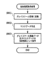
ステップ801では紙指紋情報取得部507において抽出された画像データをグレイスケールの画像データに変換する。ステップ802では、ステップ801においてグレイスケールの画像データへ変換された画像において、印刷や手書きの文字といった誤判定の要因となりうるものを取り除いて照合を行うためのマスクデータを作成する。マスクデータは“0”又は“1”の2値データである。グレイスケールの画像データにおいて、輝度信号値が第1の閾値(つまり、明るい)以上である画素については、マスクデータの値を“1”に設定する。また、輝度信号値が第1の閾値未満である画素についてはマスクデータの値を“0”に設定する。以上の処理を、グレイスケールの画像データに含まれる各画素に対して行う。ステップ803では、ステップ801においてグレイスケールに変換された画像データ及び、ステップ802において作成されたマスクデータの2つのデータを紙指紋情報として取得する。
In
紙指紋情報取得部507は、上記所定領域の紙指紋情報を不図示のデータバスを用いてRAM302に送る。これらの処理は紙指紋情報取得処理の基本フローである。
The paper fingerprint
図10は、前述した紙指紋情報取得処理において、取得領域を検出する処理を加えたフローチャートである。ステップ1001では、紙指紋情報取得部507にて抽出された画像データに対して、紙指紋を取得する領域を検出する画像領域検出手段である。詳細な処理については後述する。その次のステップ801からは前述したとおりである。
FIG. 10 is a flowchart in which processing for detecting an acquisition area is added in the paper fingerprint information acquisition processing described above.
図24は、前述した紙指紋取得処理において、紙指紋情報に画像データを含める処理を加えたフローチャートである。ステップ1001については、前述したとおりである。ステップ801、802についても前述したとおりである。ステップ2401では、ステップ1001で取得した画像データと、ステップ801で生成したグレイスケール画像データと、ステップ802で作成したマスクデータを紙指紋データとして取得する。紙指紋情報取得部507は、上記紙指紋情報を不図示のデータバスを用いてRAM302に送る。図24のフローチャートで示した処理を行い、画像データを紙指紋情報に加えた場合、紙指紋照合処理においても、画像データ照合を加えた処理を行う。
FIG. 24 is a flowchart in which processing for including image data in paper fingerprint information is added in the paper fingerprint acquisition processing described above.
図11は、ステップ1001の処理を詳細に示したフローチャートである。ステップ1101では、スキャナ画像処理部312が、スキャナ部13にて読み込まれた画像データをスキャナI/F311を介して受信する。ステップ1102では、前ステップにて受信した画像データに対して、図5の文字写真判定部506がビット(画素)単位で文字・写真などの画像領域なのか、非画像領域なのかを判定する。判定結果は1ビット信号で表され、画像データに対する判定結果は、画像・非画像情報領域情報として登録し、不図示のデータバスを用いてRAM302に送る。
FIG. 11 is a flowchart showing details of the processing in
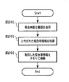
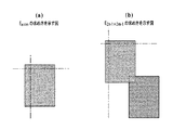
たとえば、図12(a)、12(b)で示しているような画像データ1201に対してビット(画素)単位1202で文字・写真領域を判定していく。もし検査しているビット(画素)が文字・写真と判定された場合は、そのビット(画素)を画像領域(0/1信号で言うと1)として登録する(1203)。ステップ1103では、前ステップで画像データの文字・写真判定を行った結果、画像データ全体に画像データが見つかったかどうかを判定する。もし、画像データ全体が非画像データと判定された場合は、任意の位置にて紙指紋領域を確定させて、ステップ801へ進む。画像データ内に画像領域があると判定された場合は、次のステップ1104へ進む。ステップ1104では、前ステップ1102で処理した画像データの画像・非画像領域判定情報を取得して、その情報に対して紙指紋を取得する所定のエリアサイズにて、エッジ判定を行う。エッジ判定は、前記画像・非画像領域判定情報に対して、所定のエリアサイズM×Nのビット値を加算して、そのエリア全体にどのくらい画像領域が含まれているのかを判定する。
For example, a character / photo area is determined in bit (pixel)
たとえば、図13(a)、13(b)、13(c)で示しているような画像・非画像領域判定情報1301において、所定エリア1303(3×3の太枠)でエッジ判定を行うとする。1302(網点)は画像領域を示すものとする。図13(a)の所定エリア1303の場合、非画像エリア(0信号)のみを包含しているので、判定結果は0となる。図13(b)の所定エリア1304の場合、画像エリア(1信号)のみを包含しているので、判定結果は9となる。図13(c)の所定エリア1305の場合、画像・非画像エリア混載であり、判定結果は4となる。このように、エッジ判定の結果が0以上、M×N未満であれば、画像領域を一部包含する領域ということになる。ただし、紙指紋においては取得領域内に多くの画像領域を包含すると、照合時の照合率が低下するため望ましくない。したがって、仮にM×Nを16×16としたとすると、判定結果が0〜50であれば『ほぼ非画像領域』、51〜150であれば『紙指紋所望領域』、151〜256であれば『ほぼ画像領域』と定義しておく。そして、『紙指紋所望領域』が検出された時点で取得領域を決定することが望ましい。S1105では、前ステップ1104にて紙指紋領域が検出されたかどうかを判定する。もし、所望の紙指紋領域が検出できなかった場合は、ステップ1108へ進む。紙指紋領域が検出できた場合は、ステップ1106へ進む。
For example, when edge determination is performed in a predetermined area 1303 (3 × 3 thick frame) in the image / non-image
ステップ1106では、前ステップ1104で検出された領域を紙指紋領域として決定し、領域情報を不図示のデータバスを用いてRAM302に送る。ステップ1107では、前ステップ1106で決定した領域情報に対応する、画像データをステップ1101で取得した画像データから抽出して取得する。取得した画像データは、不図示のデータバスを用いてRAM302に送る。ステップ1108では、紙指紋の取得に失敗したことをユーザに知らせるためにエラーを操作部I/F305を通して操作部12へ通知する。エラーを受信した操作部は図22で示すようなエラーメッセージを表示させる。2201はエラーメッセージ外観、2202はOKボタンを示す。
In step 1106, the area detected in the previous step 1104 is determined as a paper fingerprint area, and the area information is sent to the
復号部508は、マスキング処理部501から出力された画像データ内に符号画像データが存在する場合には、その存在を検知する。そして、検知された符号画像データを復号化して情報を取出す。
When there is code image data in the image data output from the masking
<プリンタ画像処理部315の詳細説明(図6)>
図6にプリンタ画像処理315においてなされる処理の流れを示す。
<Detailed Description of Printer Image Processing Unit 315 (FIG. 6)>
FIG. 6 shows the flow of processing performed in the
下地飛ばし処理部601は、スキャナ画像処理部312で生成されたヒストグラムを用いて画像データの下地色を飛ばす(除去する)。モノクロ生成部602はカラーデータをモノクロデータに変換する。Log変換部603は輝度濃度変換を行う。このLog変換部603は、例えば、RGB入力された画像データを、CMYの画像データに変換する。出力色補正部604は出力色補正を行う。例えばCMY入力された画像データを、テーブルやマトリックスを用いてCMYKの画像データに変換する。出力側ガンマ補正部605は、この出力側ガンマ補正部605に入力される信号値と、複写出力後の反射濃度値とが比例するように補正を行う。符合画像合成部607は、出力側ガンマ補正部605で補正された(原稿)画像データと、後述する<紙指紋情報符号化処理>で生成された符合画像データとを合成する。中間調補正部606は、出力するプリンタ部の階調数に合わせて中間調処理を行う。例えば、受取った高階調の画像データに対し2値化や32値化などを行う。
The background
なお、スキャナ画像処理部312やプリンタ画像処理部315における各処理部では、受取った画像データに各処理を施さずに出力させることも可能となっている。このような、ある処理部において処理を施さずにデータを通過させることを、以下では「処理部をスルーさせる」と表現することにする。
Each processing unit in the scanner
<紙指紋情報符号化処理>
CPU301は、紙指紋情報取得部507からRAM302に送られてきた所定領域の紙指紋情報を読出し、当該読出された紙指紋情報の符号化処理を行って符号画像データを生成すべく制御することが可能となっている。
<Paper fingerprint information encoding process>
The
なお、本明細書では、符号画像とは、二次元コード画像やバーコード画像といった画像のことを示す。 In this specification, the code image indicates an image such as a two-dimensional code image or a barcode image.
さらに、CPU301は、生成された符号画像データを不図示のデータバスを用いて、プリンタ画像処理部315内の符号画像合成部607に送信すべく制御することが可能となっている。
Further, the
なお、上記制御(符号画像の生成制御、送信制御)は、RAM302内に格納されたプログラムを実行することによって行われる。
The above control (code image generation control and transmission control) is performed by executing a program stored in the
<紙指紋情報照合処理>
CPU301は、紙指紋情報取得部507からRAM302に送られてきた紙指紋情報を読出し、当該読出された紙指紋情報と他の紙指紋情報とを照合すべく制御することが可能となっている。なお、他の紙指紋情報とは、符号画像データ内に含まれる紙指紋情報やサーバに登録されている紙指紋情報のことを意味する。
<Paper fingerprint information matching process>
The
図9は、この紙指紋情報照合処理を示すフローチャートである。本フローチャートの各ステップは、CPU301により統括的に制御される。
FIG. 9 is a flowchart showing the paper fingerprint information matching process. Each step of this flowchart is centrally controlled by the
ステップ901では、符号画像データ内に含まれる紙指紋情報やサーバに登録されている紙指紋情報をRAM302から取出す。
In step 901, the paper fingerprint information included in the code image data and the paper fingerprint information registered in the server are extracted from the
ステップ902では、紙指紋情報取得部507から送られてきた紙指紋情報と、ステップ901において取出された紙指紋情報との照合をするために、式(I)を用いて2つの紙指紋情報のマッチング度合いを算出する。一方の紙指紋情報はもう一方の紙指紋情報をずらしたものであると仮定する。式(I)に示した関数において、1画素ごとにずらし、式(I)の関数により求まる値が最小になるところ、つまり2つの紙指紋情報の差が最も小さくなるところで、2つの紙指紋情報の誤差イメージ(E)を求める。
In

式(1)においてα1はステップ901で取出された(登録されていた)紙指紋情報中のマスクデータである。f1はステップ901で取出された(登録されていた)紙指紋情報中のグレイスケール画像データである。α2はステップ902で紙指紋情報取得部507から送られてきた(今、取出されたばかりの)紙指紋情報中のマスクデータである。f2はステップ902で紙指紋情報取得部507から送られてきた(今、取出されたばかりの)紙指紋情報中のグレイスケール画像データである。
In equation (1), α 1 is mask data in the paper fingerprint information extracted (registered) in step 901. f 1 is gray scale image data in the paper fingerprint information extracted (registered) in step 901. alpha 2 is the mask data in paper fingerprint information sent from the acquisition section 507 (now just taken) paper fingerprint information at
具体的な方法を図25,35、36、37を用いて説明する。図25は、それぞれ登録されている紙指紋情報と今回得られた紙指紋情報のイメージ図を表す。それぞれ、横n画素、縦m画素から構成されているものとする。 A specific method will be described with reference to FIGS. FIG. 25 shows an image diagram of the registered paper fingerprint information and the paper fingerprint information obtained this time. Assume that each pixel is composed of horizontal n pixels and vertical m pixels.
式(1)に示した関数において、i,jをそれぞれ−n+1〜n−1、−m+1〜m−1の範囲でそれぞれ1画素毎にずらし、登録されていた紙指紋情報と今回得られたばかりの紙指紋情報の誤差値E(i,j)を(2n−1)×(2m−1)個求める。即ち、E(−n+1,−m+1)〜E(n−1,m−1)を求める。
In the function shown in Expression (1), i and j are shifted by 1 pixel in the range of −
図35(a)は、登録されている紙指紋情報の左上1画素に対して、今回得られた紙指紋情報の右下1画素だけ重なっているイメージ図を表す。この状態において、式(1)の関数により求まる値をE(−n+1,−m+1)とする。図35(b)は、図35(a)よりも今回得られた紙指紋情報を右に1画素分だけ移動したイメージ図を表す。この状態において、式(1)の関数により求まる値をE(−n+2,−m+1)とする。同様に今回得られたばかりの紙指紋情報を移動させながら演算を行う。図35(c)では、今回得られたばかりの紙指紋情報を、登録されていた紙指紋情報と重なるところまで移動させており、これによりE(0,−(m−1))が求まる。さらに、図35(d)では、今回得られた紙指紋情報を右端まで移動して、E(n−1,−m+1)を求める。このように、横方向にずらすと、E(i,j)のうちのiが1ずつ加算される。
FIG. 35A shows an image diagram in which the upper left pixel of the registered paper fingerprint information is overlapped by the lower right pixel of the obtained paper fingerprint information. In this state, the value obtained by the function of Expression (1) is E (−
同様に図36(a)では、図35(a)よりも、縦方向である下に1画素だけ今回得られた紙指紋情報を移動して、E(−n+1,−m+2)の値を求める。
Similarly, in FIG. 36 (a), the paper fingerprint information obtained this time by one pixel is moved downward in the vertical direction as compared with FIG. 35 (a) to obtain the value of E (−
さらに図36(b)は、図36(a)に対して、今回得られた紙指紋情報を右端まで移動してE(n−1,−m+2)の値を求める。 Further, FIG. 36 (b) obtains the value of E (n−1, −m + 2) by moving the paper fingerprint information obtained this time to the right end with respect to FIG. 36 (a).
図37(a)は、登録されている紙指紋情報と今回得られた紙指紋情報が,同じ位置の場合を表し、このときのE(i,j)の値をE(0,0)とする。 FIG. 37A shows a case where the registered paper fingerprint information and the paper fingerprint information obtained this time are at the same position, and the value of E (i, j) at this time is expressed as E (0,0). To do.
同様に、それぞれの紙指紋情報が少なくとも1画素以上重なるように画像をずらしながら演算を行う。最後に図37(b)のように、E(n−1,m−1)を求める。 Similarly, the calculation is performed while shifting the images so that each paper fingerprint information overlaps at least one pixel. Finally, E (n-1, m-1) is obtained as shown in FIG.
このようにして、(2n−1)×(2m−1)個の誤差値E(i,j)の集合を求める。 In this way, a set of (2n−1) × (2m−1) error values E (i, j) is obtained.
ここで、この式(1)の意味を考えるために、i=0,j=0であり、かつ、α1(x,y)=1(ただし、x=0〜n,y=0〜m)であり、かつ、α2(x−i,y−j)=1(ただし、x=0〜n,y=0〜m)の場合を考えてみることにする。つまり、α1(x,y)=1(ただし、x=0〜n,y=0〜m)であり、かつ、α2(x−i,y−j)=1(ただし、x=0〜n,y=0〜m)の場合のE(0,0)を求めることにする。 Here, in order to consider the meaning of the equation (1), i = 0, j = 0, and α 1 (x, y) = 1 (where x = 0 to n, y = 0 to m ) And α 2 (x−i, y−j) = 1 (where x = 0 to n and y = 0 to m). That is, α 1 (x, y) = 1 (where x = 0 to n, y = 0 to m), and α 2 (xi, y−j) = 1 (where x = 0). E (0,0) in the case of .about.n, y = 0 to m).
なお、i=0,j=0とは、図37(a)のように、登録されていた紙指紋情報と今回得られた紙指紋情報が同じ位置であることを示す。 Note that i = 0 and j = 0 indicate that the registered paper fingerprint information and the paper fingerprint information obtained this time are at the same position as shown in FIG.
ここで、α1(x,y)=1(ただし、x=0〜n,y=0〜m)は、登録されていた紙指紋情報の全ての画素が明るいことを示す。言い換えると、登録されていた紙指紋情報が取得された際には、紙指紋取得領域上には一切トナーやインクなどの色材やゴミがのっていなかったことを示す。 Here, α 1 (x, y) = 1 (where x = 0 to n, y = 0 to m) indicates that all pixels of the registered paper fingerprint information are bright. In other words, when the registered paper fingerprint information is acquired, it indicates that no color material such as toner or ink or dust has been placed on the paper fingerprint acquisition area.
また、α2(x−i,y−j)=1(ただし、x=0〜n,y=0〜m)は、今回取得した紙指紋情報の全ての画素が明るいことを示す。言い換えると、今取得されたばかりの紙指紋情報が取得された際には、紙指紋取得領域上には一切トナーやインクなどの色材やゴミがのっていなかったことを示す。 Further, α 2 (x−i, y−j) = 1 (where x = 0 to n, y = 0 to m) indicates that all pixels of the paper fingerprint information acquired this time are bright. In other words, when the paper fingerprint information just acquired is acquired, it indicates that no color material such as toner or ink or dust is on the paper fingerprint acquisition area.
このように、α1(x,y)=1とα2(x−i,y−j)=1とが全ての画素において成り立つ時、(1)式は、 Thus, when α 1 (x, y) = 1 and α 2 (x−i, y−j) = 1 hold in all pixels, the equation (1) becomes
と表されることになる。 Will be expressed.
この{f1(x,y)−f2(x,y)}2は、登録されていた紙指紋情報中のグレイスケール画像データと、今取出されたばかりの紙指紋情報中のグレイスケール画像データとの差の二乗値を示す。従って、この(1)式は、二つの紙指紋情報同士の各画素における差の二乗を合計したものになる。つまり、f1(x,y)とf2(x,y)とが似ている画素が多ければ多いほど、このE(0,0)は、小さな値を取ることになる。 This {f 1 (x, y) −f 2 (x, y)} 2 is the gray scale image data in the registered paper fingerprint information and the gray scale image data in the paper fingerprint information just extracted. The square value of the difference between Therefore, this equation (1) is the sum of the squares of the differences in each pixel between the two pieces of paper fingerprint information. That is, the more pixels f 1 (x, y) and f 2 (x, y) are similar, the smaller this E (0, 0) will be.
以上説明したのは、E(0,0)の求め方であるが、同じようにして他のE(i,j)を求めていく。ちなみに、f1(x,y)とf2(x,y)とが似ている画素が多ければ多いほどE(i,j)が小さな値を取ることから、
E(k,l)=min{E(i,j)}である場合、登録されていた紙指紋情報を取得した際の位置と、今取得されたばかりの紙指紋情報を取得した際の位置とは、互いにk,lずれていたことがわかる。
What has been described above is how to obtain E (0,0), but other E (i, j) are obtained in the same manner. Incidentally, since E (i, j) takes a smaller value as the number of pixels in which f 1 (x, y) and f 2 (x, y) are similar is larger,
If E (k, l) = min {E (i, j)}, the position when the registered paper fingerprint information is acquired, and the position when the paper fingerprint information just acquired is acquired It can be seen that they were shifted from each other by k and l.
<αの意義>
式(1)の分子は、{f1(x,y)−f2(x−i,y−j)}2に対してα1とα2とがかけられた結果を意味する(正確には、さらにΣ記号により合計値が求められている)。このα1とα2は、濃い色の画素は0、薄い色の画素は1を示す。
<Significance of α>
The numerator of formula (1) means the result of multiplying {f 1 (x, y) -f 2 (xi, yj)} 2 by α 1 and α 2 (exactly Is further determined by the Σ symbol). Α 1 and α 2 indicate 0 for a dark pixel and 1 for a light pixel.
従って、α1とα2とのうちどちらか一方(又は両方)が0の場合には、α1α2{f1(x,y)−f2(x−i,y−j)}2は0になることになる。 Accordingly, when one (or both) of α 1 and α 2 is 0, α 1 α 2 {f 1 (x, y) −f 2 (xi, y−j)} 2 Will be 0.
即ち、どちらか一方(または両方)の紙指紋情報において対象とする画素が濃い色であった場合には、その画素における濃度差は考慮しないことを示している。これは、ゴミや色材がのってしまった画素を無視するためである。 That is, when one or both (or both) of the paper fingerprint information has a dark pixel, the density difference between the pixels is not considered. This is for ignoring pixels on which dust or color material has been placed.
この処理により、Σ記号により合計する数が増減するため、総数Σα1(x,y)α2(x−i,y−j)で割ることで正規化を行う。なお、式(I)の分母にあるΣα1(x,y)α2(x−i,y−j)が0になる誤差値E(i,j)は、後述の誤差値の集合(E(−(n−1),−(m−1))〜E(n−1,m−1))には含めないものとする。 As a result of this processing, the total number increases or decreases depending on the Σ symbol, so normalization is performed by dividing by the total number Σα 1 (x, y) α 2 (xi, y−j). Note that an error value E (i, j) in which Σα 1 (x, y) α 2 (x−i, y−j) in the denominator of the equation (I) becomes 0 is a set of error values (E (-(N-1),-(m-1)) to E (n-1, m-1)) are not included.
<マッチング度合いの決定方法>
上述したように、E(k,l)=min{E(i,j)}である場合、登録されていた紙指紋情報を取得した際の位置と、今取得されたばかりの紙指紋情報を取得した際の位置とは互いにk,lずれていたことがわかる。
<Determination method of matching degree>
As described above, when E (k, l) = min {E (i, j)}, the position when the registered paper fingerprint information is acquired and the paper fingerprint information just acquired are acquired. It can be seen that the positions were shifted by k and l from each other.
続いて、二つの紙指紋情報がどれだけ似ているのかを示す値(この値を、マッチング度合いと称する)を、そのE(k,l)及び他のE(i,j)を使って求める。 Subsequently, a value indicating how much the two pieces of paper fingerprint information are similar (this value is referred to as a matching degree) is obtained using the E (k, l) and other E (i, j). .
まず、(1)の関数により求まった誤差値の集合(例えば、E(0,0)=10※,E(0,1)=50,E(1,0)=50,E(1,1)=50)から平均値(40)を求める。・・・(A)
なお、※は、値とは関係がない。注目して頂くために記載しただけである。注目して頂きたかった理由は後述する。
First, a set of error values obtained by the function of (1) (for example, E (0,0) = 10 *, E (0,1) = 50, E (1,0) = 50, E (1,1 ) = 50) to obtain the average value (40). ... (A)
Note that * is not related to the value. They are listed only for your attention. The reason I wanted to pay attention will be described later.
次に、平均値(40)から各誤差値(10※,50,50,50)を引いて、新たな集合(30※,−10,−10,−10)を求める。・・・・(B)
そして、この新たな集合から標準偏差(30×30+10×10+10×10+10×10=1200,1200/4=300,√300=10√3=約17)を求める。そして、上記新たな集合を17で割り、商を求める(1※,−1,−1,−1)。・・・・(C)
そして、求められた値のうちの最大値をマッチング度合い(1※)とする。なお、この1※という値は、E(0,0)=10※という値と対応した値である。E(0,0)というのは、今回の場合、E(0,0)=min{E(i,j)}を満たす値である。
Next, each error value (10 *, 50, 50, 50) is subtracted from the average value (40) to obtain a new set (30 *, −10, −10, −10). .... (B)
Then, a standard deviation (30 × 30 + 10 × 10 + 10 × 10 + 10 × 10 = 1200, 1200/4 = 300, √300 = 10√3 = about 17) is obtained from this new set. Then, the new set is divided by 17 to obtain a quotient (1 *, -1, -1, -1). .... (C)
And let the maximum value of the calculated | required values be a matching degree (1 *). The
<マッチング度合いの決定方法の概念的な説明>
上記マッチング度合いの決定方法を行う処理は、結局、複数の誤差値集合の中で最も小さな誤差値が、平均的な誤差値とどれだけ離れているかを計算する(A及びB)。
<Conceptual explanation of how to determine the degree of matching>
The process of performing the matching degree determination method eventually calculates how far the smallest error value in the plurality of error value sets is from the average error value (A and B).
そして、その離れ具合を標準偏差で割ることでマッチング度合いを求める(C)。 Then, the degree of matching is obtained by dividing the degree of separation by the standard deviation (C).
最後にマッチング度合いを閾値と比較することで、照合結果を得る(D)。 Finally, a matching result is obtained by comparing the matching degree with a threshold (D).
なお、標準偏差は、「各誤差値と平均値との差」の平均的な値を意味する。言い換えると、標準偏差は、集合の中で大体どれくらいのばらつきが全体的に生じているかを示す値である。 The standard deviation means an average value of “difference between each error value and the average value”. In other words, the standard deviation is a value indicating how much variation occurs in the entire set.
このような全体的なばらつき値で上記離れ具合を割ることで、min{E(i,j)}が集合E(i,j)の中でどれだけ小さいか(突出して小さいか、ちょっと小さいか)がわかることになる。 By dividing the above degree of separation by such an overall variation value, how small is min {E (i, j)} in the set E (i, j) (projectingly small or slightly small) ) Will be understood.
そして、min{E(i,j)}が集合E(i,j)の中で非常に突出して小さい場合に有効と判断し、それ以外の場合に無効と判断する(D)。 Then, it is determined to be valid when min {E (i, j)} is very prominent and small in the set E (i, j), and is invalid otherwise (D).
<min{E(i,j)}が集合E(i,j)の中で非常に突出して小さい場合のみ有効と判断する理由>
ここで、登録されていた紙指紋情報と、今取得されたばかりの紙指紋情報とが、同じ紙から取得されたと仮定する。
<Reason to determine that min {E (i, j)} is effective only when it is very small in the set E (i, j)>
Here, it is assumed that the registered paper fingerprint information and the paper fingerprint information just acquired are acquired from the same paper.
すると、登録されていた紙指紋情報と、今取得されたばかりの紙指紋情報とが極めて一致する場所(ずれ位置)があるはずである。この時、このずれ位置では、登録されていた紙指紋情報と、今取得されたばかりの紙指紋情報とが極めて一致するため、E(i,j)は非常に小さくなるはずである。 Then, there should be a place (shift position) where the registered paper fingerprint information and the paper fingerprint information just acquired are very consistent. At this time, at this misalignment position, the registered paper fingerprint information and the paper fingerprint information just acquired are very coincident, so E (i, j) should be very small.
一方、このずれ位置から少しでもずらすと、登録されていた紙指紋情報と今取得されたばかりの紙指紋情報には何ら関連性がなくなる。従って、E(i,j)は通常の大きな値になるはずである。 On the other hand, if the position is slightly shifted from this position, the registered paper fingerprint information and the paper fingerprint information just acquired are no longer relevant. Therefore, E (i, j) should be a normal large value.
そのため、「二つの紙指紋情報が同じ紙から取得された」という条件は、「最も小さなE(i,j)が集合E(i,j)の中で突出して小さい」という条件と一致する。 Therefore, the condition that “two pieces of paper fingerprint information are acquired from the same paper” matches the condition that “the smallest E (i, j) protrudes and is small in the set E (i, j)”.
再び<紙指紋情報照合処理>について説明する。 The <paper fingerprint information matching process> will be described again.
ステップ903では、ステップ902において求められた2つの紙指紋情報のマッチング度合いと所定の閾値との比較を行って、「有効」「無効」を決定する。なお、マッチング度合いのことを類似度と称することもある。また、マッチング度合いと所定の閾値との比較結果のことを、照合結果と称することもある。
In step 903, the matching degree of the two pieces of paper fingerprint information obtained in
コントローラ11の説明は以上である。
The description of the
<操作画面の説明>
図7は画像形成装置10における初期画面である。領域701は、画像形成装置10がコピーできる状態にあるか否かを示し、かつ設定したコピー部数を示す。原稿選択タブ704は原稿のタイプを選択するためのタブであり、このタブが押し下げられると文字、写真、文字/写真モードの3種類の選択メニューをポップアップ表示される。フィニッシングタブ706は各種フィニッシングに関わる設定を行うためのタブである。両面設定タブ707は両面読込み及び両面印刷に関する設定を行うためのタブである。読み取りモードタブ702は原稿の読み取りモードを選択するためのタブである。このタブが押し下げられるとカラー/ブラック/自動(ACS)の3種類の選択メニューがポップアップ表示される。なお、カラーが選択された場合にはカラーコピーが、ブラックが選択された場合にはモノクロコピーが行われる。また、ACSが選択された場合には、上述したモノクロカラー判定信号によりコピーモードが決定される。
<Explanation of operation screen>
FIG. 7 shows an initial screen in the
領域708は、紙指紋情報登録処理を選択するためのタブである。紙指紋情報登録処理については、後述する。領域709は、紙指紋情報照合処理を選択するためのタブである。この紙指紋情報照合処理については、後述する。
An
領域710は、紙指紋情報登録処理においてセキュリティレベルを設定するためのタブである。セキュリティレベル設定処理については後述する。領域711は、紙指紋情報登録処理において、照合率を設定するためのタブである。照合率設定処理については後述する。
An
図14はセキュリティ設定処理を示しているフローチャートである。ステップ1401では、前述した領域710のタブが選択された情報を受信して、セキュリティ設定画面を表示する。セキュリティ設定画面の一例を図15に示す。1501はセキュリティ設定画面の外観を示している。1502はセキュリティレベルを『高い』に設定するためのタブである。1503はセキュリティレベルを『普通』に設定するためのタブである。ステップ1402では、前述したセキュリティ設定画面で設定されたセキュリティレベルを取得する。ステップ1403では、前ステップで取得したセキュリティレベルを不図示のデータバスを用いてRAM302に送る。前述したセキュリティレベルは、システムに応じて種類を増減させても良い。
FIG. 14 is a flowchart showing the security setting process. In
図19は照合率設定処理を示しているフローチャートである。ステップ1901では、前述した領域711のタブが選択された情報を受信して、照合率設定画面を表示する。照合率設定画面の一例を図20に示す。2001は照合率設定画面の外観を示している。2002は照合率を指定するスライダーバー、2003は前記スライダーバー上を移動する矢印、2004はOKボタンを示している。矢印2003を左右に移動させて照合率を設定する。左に行くほど照合率は低く、右に行くほど高くなる。ここで示した設定方法は一例であるため、照合率が設定できるのであれば、この構成でなくてもかまわない。ステップ1902では、前述した照合率設定画面で設定した照合率を取得する。1903では、前ステップで取得した照合率を不図示のデータバスを用いてRAM302に送る。
FIG. 19 is a flowchart showing the collation rate setting process. In
<紙指紋情報登録処理のタブが押下された際の動作>
続いて、図7に示す紙指紋情報登録タブ708がユーザにより押下された後にスタートキーが押下された際に、実行される紙指紋情報登録処理について説明する。
<Operation when the tab for paper fingerprint information registration processing is pressed>
Next, a paper fingerprint information registration process executed when the user presses the paper fingerprint
図16は、紙指紋情報取得モード時の全体処理を示すフローチャートである。ステップ1601では、CPU301は、スキャナ部13で読み取られた印字済み出力用紙を、画像データとしてスキャナI/F311を介してスキャナ画像処理部312に送るように制御する。出力用紙はステップ1601で読み込まれた後に、手差しトレイにセットされる。
FIG. 16 is a flowchart showing the overall processing in the paper fingerprint information acquisition mode. In step 1601, the
ステップ1602では、スキャナ画像処理部312は、通常読み取り時のゲイン調整値よりも小さいゲイン調整値を、シェーディング補正部500に設定する。そして、画像データに対して上記小さいゲイン調整値を適用することで得られた各輝度信号値を紙指紋情報取得部507に対して出力する。その後、出力データに基づいて、紙指紋情報取得部507は、紙指紋情報を取得する。紙指紋情報の取得は図11に示したフローチャートのとおり処理される。詳細については前述したとおりである。前述の領域710でセキュリティレベルが設定されているときの紙指紋情報取得処理については後述する。また、前述の領域711で照合率が設定されているときの紙指紋情報取得処理については後述する。そして、当該取得された紙指紋情報を不図示のデータバスを用いてRAM302に送る。ステップ1602での処理が終了すると、ステップ1603の処理が開始する。
In step 1602, the scanner
ステップ1603では、CPU301は、紙指紋情報を符号化して符号画像を生成し、当該生成された符号画像データをプリンタ画像処理部315内の符号画像合成部607に送信すべく制御する。
In
ステップ1604では、ステップ1603で生成された符号画像データと出力する紙に印刷する画像データ(本フローでは既に印字済みのデータであるため、画像データはなし)とを符号画像合成部607が合成する。そして、当該合成により得られた合成画像データを中間調補正部606が、出力するプリンタ部の階調数に合わせて中間調処理を行う。中間調処理後の合成画像データはプリンタI/F314を介してプリンタ部14に送られる。
In
<紙指紋情報登録処理(セキュリティレベル設定時)>
図18は、前述したセキュリティレベルが設定されているときの紙指紋情報登録処理について詳細を示している。ステップ1101は前述したとおりである。ステップ1801では、前述したセキュリティ設定処理によりRAM302に設定されたセキュリティレベル情報を取得する。ステップ1102については、前述したとおりである。ステップ1802では、ステップ1802により取得したセキュリティレベルがどのレベルで設定されているかを判定する。もし、セキュリティレベルが高であると判定された場合、ステップ1804へ進む。セキュリティレベルが高ではなく、図15で例に出した『普通』などであった場合は、ステップ1803へ進む。ステップ1803では、前述したステップ1104のエッジ判定と同様の処理を行う。しかしここでは、所定サイズ領域が非画像領域であることを合わせて検査する。検査の方法としては、画像データのある位置から検査を開始して、非画像領域が抽出された時点でこのステップを終了しても良い。ステップ1804では、前述したステップ1104のエッジ判定と同様の処理を行う。しかしここでは、所定サイズ領域が画像を包含する領域であることを合わせて検査する。検査の方法としては、画像データのある位置から検査を開始して、画像領域を包含する領域が抽出された時点で、このステップを終了しても良い。
<Paper fingerprint information registration process (when security level is set)>
FIG. 18 shows details of the paper fingerprint information registration process when the security level described above is set.
ステップ1105からステップ1107は、前述した処理と同様である。ステップ1803またはステップ1804で抽出された領域を紙指紋領域として決定し、その領域に対応する画像データを取得する。また、ステップ1803またはステップ1804で領域が抽出できなかったときは、エラーを送信する。このように、前述したセキュリティレベルに応じて、エッジ判定による画像領域の抽出条件を分岐することにより、取得する紙指紋領域を『白地のみ』や『文字包含』と変更することが可能である。ちなみに、セキュリティレベルは前述したとおり複数種類存在しても構わない。その場合は、前述のステップ1802でセキュリティレベルに応じた分岐を行い、エッジ判定処理を段階的に行えばよい。たとえば、セキュリティレベル『最低』であれば、『白地』領域を抽出し、『低』であれば『10%文字包含』領域を抽出などとする。
<紙指紋情報登録処理(照合率設定時)>
図21は、前述した照合率が設定されているときの紙指紋情報登録処理について詳細を示している。ステップ1101は前述したとおりである。ステップ2101では、前述した照合率設定処理によりRAM302に設定された照合率情報を取得する。ステップ1102については、前述したとおりである。ステップ2102では、ステップ2101で取得した照合率情報から、取得する紙指紋領域の数を算出する。たとえば、照合率を0(低い)〜100(高い)で定量化する。もし、0〜20であれば1つ、21〜40であれば2つ、41〜60であれば3つ、61〜80であれば4つ、81〜100であれば5つのように定義しておき、取得した照合率にあわせて紙指紋の数を算出する方法でも良い。ステップ2103では、ステップ2102で取得した紙指紋の取得数を定数Nに代入する。ステップ2104では、変数Xを定義して0を代入する(初期化を行う)。変数Xは紙指紋領域の数を格納する。ステップ2105では、前述したエッジ判定処理を行い、所定サイズ領域が画像包含領域であることを検査する。このステップでは、画像サイズの開始位置から検査を開始して、画像包含領域が抽出された時点で終了するなお、一度取得した紙指紋領域は再度取得されることはないこととする)。
<Paper fingerprint information registration process (when collation rate is set)>
FIG. 21 shows details of the paper fingerprint information registration process when the above-described collation rate is set.
ステップ2106では、ステップ2105で画像包含領域が抽出されたかどうかを判定する。もし画像包含領域が抽出されていなかった場合は、ステップ2108へ進む。画像包含領域が抽出された場合は、ステップ2107へ進む。ステップ2107では、ステップ2104で定義した変数Xをインクリメントする。ステップ2108では、定数Nと変数Xとが等しいかどうかを判定する。また、ステップ2105のエッジ判定が、画像データの全領域で検査終了しているかどうかも判定する。どちらの判定ともにNOであった場合は、ステップ2105へ進む。もし定数Nと変数Xが一致すると判定されたら、ステップ1106へ進む。また、画像データの全領域で検査終了していると判定された場合は、ステップ2109へ進む。ステップ2109では、変数Xが0と等しいかどうかを判定する。もし、0と等しいと判定されたら、ステップ1108へ進む。ステップ1108の処理は、前述したとおりである。もし、0と一致しなかったら、ステップ2110へ進む。ステップ2108で変数Nと一致していないと判定され、さらにステップ2109で0とも一致しないと判定されているため、変数Xは取得した照合率によって算出された紙指紋の取得数には満たないが、0ではないということである。したがって、ステップ2110ではその旨をユーザに知らせるために警告を操作部I/F305を通して操作部12へ通知する。警告を受信した操作部は図23に示すような警告メッセージを表示させせる。2301は警告メッセージ外観、2302は警告文字列、2303は『はい』ボタン、2304は『いいえ』ボタンを示す。ステップ2111では、前記警告メッセージにて、『はい』もしくは『いいえ』のどちらが押下されたかを判定する。『はい』ボタンが押下されたときは、ユーザが設定した照合率を満たすほど、紙指紋の数は取得できていないが、取得できた数で処理を続行するので、ステップ1106へ進む。『いいえ』が押下されたときは、紙指紋取得処理を中断し、終了する。
In
<紙指紋情報照合処理のタブが押下された際の動作>
続いて、図7に示す紙指紋情報照合タブ709がユーザにより押下された後にスタートキーが押下された際の動作について図17を用いて説明する。
<Operation when paper fingerprint information matching tab is pressed>
Next, an operation when the start key is pressed after the paper fingerprint
ステップ1701では、CPU301は、スキャナ部13で読み取られた原稿を、画像データとしてスキャナI/F311を介してスキャナ画像処理部312に送るように制御する。ステップ1702では、スキャナ画像処理部312は、この画像データに対して図5に示す処理を行い、新たな画像データと共に属性データを生成する。また、この属性データを画像データに付随させる。さらに、このステップ1702では、スキャナ画像処理部312内の紙指紋情報取得部507は、紙指紋情報を取得する(紙指紋情報を取得するために、シェーディング補正部500のゲイン調整を行うなどの構成は上述した通りである)。そして、当該取得された紙指紋情報を不図示のデータバスを用いてRAM302に送る。さらに、このステップ1702では、スキャナ画像処理部312内の復号部508は、符号画像が存在する場合に、当該符号画像を復号して情報を取得する。そして、当該取得された情報を不図示のデータバスを用いてRAM302に送る。
In
ステップ1703では、CPU301は、紙指紋情報照合処理を行う。この紙指紋情報照合処理については、<紙指紋情報照合処理>で図9を用いて説明した通りである。ステップ1704では、CPU301は、<紙指紋情報照合処理>により得られた結果(有効か無効か)を操作部12の表示画面上に表示するように制御する。
In
[実施形態2]
画像形成装置の機体内にスキャナを搭載したときの本発明の実施形態について説明する。
[Embodiment 2]
An embodiment of the present invention when a scanner is mounted in the image forming apparatus will be described.
図26は、画像形成装置に機体内の構造を示している。プリント時は、シート収納庫より用紙を引き出し、感光ドラムにおいて用紙に画像を乗せ、定着部で用紙上の画像を定着させるという一連の処理を行う。実施形態2では、定着部の後工程にスキャナを搭載することにより、画像形成・読み取り・紙指紋情報登録処理を一連の処理で実施するようにしている。 FIG. 26 shows the internal structure of the image forming apparatus. At the time of printing, a series of processing is performed in which the sheet is pulled out from the sheet storage case, the image is placed on the sheet on the photosensitive drum, and the image on the sheet is fixed by the fixing unit. In the second embodiment, the image forming / reading / paper fingerprint information registration process is performed by a series of processes by mounting a scanner in the subsequent process of the fixing unit.
図27は本実施形態における画像形成装置の機体の内部構造を示している。2701は機体内部に搭載されたスキャナ部である。
FIG. 27 shows the internal structure of the body of the image forming apparatus in this embodiment.
<紙指紋情報登録処理のタブが押下された際の動作>
本画像形成装置を用いて、図7に示す紙指紋情報登録タブ708がユーザにより押下された後にスタートキーが押下された際に、実行される紙指紋情報登録処理を用いて説明する。
<Operation when the tab for paper fingerprint information registration processing is pressed>
A description will be given using a paper fingerprint information registration process executed when the start key is pressed after the user presses the paper fingerprint
図28は、紙指紋情報登録処理の全体フローを示している。ステップ2801では、例えばPCのような機器から送信された印刷情報に基づいて、用紙上に画像形成を行う処理を実行する。画像形成の処理については既知の技術であるため、詳細な説明は省く。ステップ2802では、定着部で画像形成が終了したら、排紙を行う前に前記画像形成装置内に搭載されたスキャナ部2701で、画像読み取り処理を行う。ステップ1602から1604は、実施形態1で説明した処理と同様である。
FIG. 28 shows the overall flow of the paper fingerprint information registration process. In step 2801, a process for forming an image on a sheet is executed based on print information transmitted from a device such as a PC. Since the image forming process is a known technique, a detailed description thereof is omitted. In step 2802, when image formation is completed in the fixing unit, an image reading process is performed by the
このように、画像形成装置内にスキャナを搭載した実施形態では、画像形成・読み取り・紙指紋情報登録を機体内の処理のみで完結することができる。 As described above, in the embodiment in which the scanner is mounted in the image forming apparatus, the image formation / reading / paper fingerprint information registration can be completed only by the processing in the apparatus.
[実施形態3]
実施形態1では、紙指紋情報登録処理において、画像領域が一部含まれている領域(画像包含領域)を紙指紋登録領域とするために、ある閾値の画像領域を包含した領域を紙指紋領域に決定する実施形態を述べた。具体的には、図11のフローチャートのようにスキャナ部13で読み取った所定の大きさの領域に対してエッジ判定を行い、画像領域の包含を判定した。ここでは別の実施形態として、紙指紋領域として適している領域、具体的には最も紙指紋の照合率が高い領域を紙指紋領域に決定する実施形態をさらに詳しい説明と共に述べる。なお、最も照合率の高い領域を決定すること以外の制御や手段は、実施形態1と同じであるため、ここでは実施形態1との差分のみ(図11の別の実施形態)を述べる。
[Embodiment 3]
In the first embodiment, in the paper fingerprint information registration process, an area including an image area with a certain threshold is used as a paper fingerprint registration area in order to set an area including an image area (image inclusion area) as a paper fingerprint registration area. The embodiment to be determined has been described. Specifically, as shown in the flowchart of FIG. 11, edge determination is performed on an area of a predetermined size read by the
べた黒のような印字が多い領域では紙の繊維を鮮明に読み取れないため、紙指紋の照合時率の照合率は低くなる。そのため所定の大きさの領域において画像領域が少ない、つまりエッジ判定の結果が小さい領域の照合率は高くなる。これを用いて、最も照合率の高い紙指紋領域を見つける方法を以下に記載する。 In a region where there are many prints such as solid black, paper fibers cannot be read clearly, and the collation rate of the paper fingerprint collation rate is low. For this reason, the collation rate of an area having a small image area in an area of a predetermined size, that is, an area having a small edge determination result is high. A method for finding the paper fingerprint region with the highest collation rate using this will be described below.
図29は、ステップ1001の画像領域検出処理において最も照合率の高い紙指紋領域を決定するための制御を表したフローチャート図である。
FIG. 29 is a flowchart showing the control for determining the paper fingerprint region with the highest collation rate in the image region detection processing in
ステップ1101では、実施形態1と同じように、スキャナ画像処理部312が、スキャナ部13にて読み込まれた画像データをスキャナI/F311を介して受信する。
In
そして、ステップ2902では、エッジ判定の結果(以下、エッジ判定値)の初期化と、エッジ判定を行う所定の大きさの領域(以下、判定領域)の開始点の初期化(ここでは紙の左上隅)を行う。なお、ここではエッジ判定の初期値を10(MIN=10)とし、判定領域は3×3固定のエリアサイズとし、開始点は判定領域の左上の位置を表すこととする(これを図30に示す)。
In
以下で、受信データにおいてエッジ判定(実施形態1と同じ判定)を行う制御を述べる。まずステップ2902において、ステップ1101で読み込んだ画像データにおいて判定領域の開始点を変更する(ただし初回時は初期化した開始点のままとする)。変更方法としては様々な方法が考えられるが、ここでは図31のように一度判定した判定領域を再度判定することがないように、開始点を3ずつ変更する方法を用いる。そしてステップ2903で、この開始点を基準とする判定領域のエッジ判定値を求める。このエッジ判定値とこれまでの最小のエッジ判定値を比較する(ステップ2904)。もし、このエッジ判定値が最小のエッジ判定値よりも小さい場合は、この値を最小のエッジ判定値とする(ステップ2905)。
Hereinafter, control for performing edge determination (same determination as in the first embodiment) on received data will be described. First, in
この上記の制御(ステップ2903〜2906)を、次にステップ2903で開始点を変更した場合に、変更可能なら繰り返し行う(ここでは図31における右下の領域の開始点まで繰り返す。これがステップ2906)。変更不可能になった場合は、ステップ2903で設定した最小のエッジ判定値が一度でも変更されているか確認する(ステップ2907)。変更されていない場合は、エッジ処理が正常に行われていない可能性があるため実行エラーを操作部12に送信する(ステップ1108)。変更されている場合は、現在の最小のエッジ判定値になっている領域を紙指紋領域に決定し(ステップ1106)、この領域に対応する画像データを取得する(ステップ1107)。
The above control (
以上の制御により最も照合率の高い紙指紋領域を見つけることが可能となる。 The above control makes it possible to find the paper fingerprint region with the highest collation rate.
<派生形態1>
なお、本実施形態のステップ2901において、初期化としてエッジ判定値の最小値を任意の値(ここでは10)とした。しかし任意の値ではなく、ステップ1101で受信した画像データにブロックセレクションを行い、判定を行う所定の領域サイズにおいて文字や画像が少ない領域を求め、この領域に対して求めたエッジ判定値をMINに置き換えてもよい。ブロックセレクションは既知の技術(参考文献:特開平9−51388号公報など)であり、画像データを構成する各画素のイメージを解析して、その連結性を探索すると共に、検出した連結成分の分類を行うものである(詳細は省略する)。この技術によりテキストや黒画像を含む最小の矩形を検知することができるため、黒画像が少ない判定領域を見つけることが可能となる。なおブロックセレクションを行う対象となる画像データは多値2値変換部324によりあらかじめ2値の画像データに変換したものを用いるものとする。
<Derived
In
<派生形態2>
また、ステップ1107において、最も照合率が高くなる紙指紋領域の場所と紙を一意に認識するための情報を関連付けて記憶もしくは紙に印刷することを行えば、特定の紙に対する紙指紋情報を容易に見つけることが可能となる。
<Derived
Further, in
<派生形態3>
また、ステップ1101でスキャンした画像データを受信するが、この際に裏面と表面の両方の画像データを受信し、表面と裏面の両方の中から最適、もしくはある閾値以上の照合率となる紙指紋領域を探すことも可能である。
<Derived
In addition, the image data scanned in
<派生形態4>
また、この実施形態は実施形態1とも組み合わせが可能である(実施形態2で最も照合率の高い領域を決定する際に、白領域のみのものは除くことも追加することが可能である)。
<Derived
This embodiment can also be combined with the first embodiment (when determining the region with the highest collation rate in the second embodiment, it is possible to add only the white region).
[実施形態4]
実施形態1、3では、紙指紋情報登録処理において、スキャナ部13で読み取った所定の大きさの領域に対してエッジ判定を行う実施形態を述べた。ここでは別の実施形態として、ある開始位置を元にエッジ判定を行う際に領域の大きさを変更することで、照合可能な紙指紋領域を検出する実施形態を述べる。なお、認識可能な紙指紋領域を検出すること以外の制御や手段は、実施形態1、3と同じであるため、ここでは差分のみ(図11の別の実施形態)を述べる。
[Embodiment 4]
In the first and third embodiments, in the paper fingerprint information registration process, an embodiment is described in which edge determination is performed on a region having a predetermined size read by the
エッジ判定を行う領域にべた黒のような印字が多い画像しかない場合に、紙の繊維を鮮明に読み取れないため、紙指紋の照合時率の照合率は低くなる。そのため読み取る領域を拡大することで、べた黒以外の領域を増やし、照合可能な指紋領域を検出する方法を以下に記載する。 When there is only an image with many solid black prints in the edge determination region, the fiber of the paper cannot be read clearly, and the collation rate of the paper fingerprint collation rate is low. Therefore, a method of detecting a fingerprint area that can be collated by enlarging the area to be read to increase the area other than solid black will be described below.
図32は、ステップ1001の画像領域検出処理において照合可能な指紋領域を決定するための制御を表したフローチャート図である。ステップ1101では、実施形態1と同じように、スキャナ画像処理部312が、スキャナ部13にて読み込まれた画像データをスキャナI/F311を介して受信する。そして、ステップ3201では、エッジ判定を行う所定の領域(以下、判定領域)の大きさを初期化する(ここでは領域はN×Nのエリアサイズとし、N=0とする)。
FIG. 32 is a flowchart showing control for determining fingerprint regions that can be collated in the image region detection processing in
以下で、受信データにおいて変更した領域における白領域判定を行う制御を述べる。なおこの白画像領域判定とは、実施形態1のエッジ判定と同じ制御であるが、画像領域がどれくらい含まれているかではなく、白領域がどれくらい含まれているかを求めるものである。ここでは、白領域が10より大きい場合に紙指紋の照合が可能と判断することにする(つまり白領域判定の結果が10以下の場合は読み取れない領域が多いため、この紙の紙指紋は照合不可能とみなす)。 Hereinafter, control for performing white area determination in an area changed in received data will be described. This white image area determination is the same control as the edge determination in the first embodiment, but it determines not only how much image area is included but how much white area is included. Here, when the white area is larger than 10, it is determined that the paper fingerprint can be collated (that is, when the white area determination result is 10 or less, there are many areas that cannot be read. It is considered impossible).
まずステップ3202において、エッジ判定を行う領域の大きさを変更(拡大)する。変更方法としては様々な方法が考えられるが、ここでは図33のようにある開始点(ここでは紙の左上隅)を基準にし、ある一定の割合で判定領域を拡大する方法を用いる。そしてステップ3203で、この判定領域のエッジ判定値を求める。そしてステップ3204で、このエッジ判定値がある特定の閾値(ここでは10)よりも大いかどうかの判定を行う。もし、白領域判定値が10以下の場合は、次にステップ3203で変更可能か判定し(判定領域が紙のサイズより大きくなる場合は変更不可能)、変更可能なら繰り返しステップ3202〜3204を行う(ここでは図33のN=5まで繰り返す)。変更不可能になった場合は、認証可能な指紋領域が検知できていないため実行エラーを操作部12に送信する(ステップ1108)。一方、白領域判定値が10より大きくなった場合は、この領域を紙指紋領域に決定し(ステップ1106)、この領域に対応する画像データを取得する(ステップ1107)。
First, in step 3202, the size of the area for edge determination is changed (enlarged). Various methods can be considered as the changing method. Here, as shown in FIG. 33, a method of enlarging the determination area at a certain ratio with a certain starting point (here, the upper left corner of the paper) as a reference is used. In
以上の制御により照合可能な紙指紋領域を見つけることが可能となる。 The paper fingerprint region that can be collated can be found by the above control.
<派生形態>
なお、この実施形態は実施形態1や実施形態3との組み合わせも可能である(実施形態3と組み合わせることで、照合可能かつ認識率が最も高い指紋領域を検知することも可能となる)。
<Derived form>
This embodiment can also be combined with
[実施形態5]
これまでの実施形態では、図11のステップ1101にあるように、印字された原稿の読み取りを行い、指紋領域の決定を行ってきた。しかしこの実施形態では、印字を行う前に紙指紋領域を決定する方法を述べる。これにより、印字を行う前に紙指紋領域が検知できるかどうかの判定や、紙指紋領域に応じて印字を予定していた画像データの変更(印字しない、もしくは濃度などの変更)を行うことが可能となる。なお、印字を行う前のデータから紙指紋領域を検出すること以外の制御や手段は、実施形態1、3、4と同じであるため、ここでは差分のみ(図11の別の実施形態)を述べる。
[Embodiment 5]
In the embodiments so far, as in
図34は、ステップ1001の画像領域検出処理において照合可能な指紋領域を決定するための制御を表したフローチャート図である。
FIG. 34 is a flowchart showing control for determining a fingerprint region that can be collated in the image region detection processing in
ステップ3401では、LAN50やWAN331を経由してPCからの印刷データ(例えばPDLデータ)を受け取る。次にこの印刷データをCPU301の制御により解釈し、RIP328に中間データを送る。そしてRIP328でレンダリングを行い、ビットマップデータを生成する(ステップ3401)。なおこのPDLデータを受け取り、ビットマップデータを生成する処理は既知のものとし、ここでは詳細を省略する。そしてすぐに印刷処理を行うのではなく、多値2値変換部324により2値にした画像データを作成し、この画像データにおいて実施形態1や3のエッジ判定処理を適用し、紙指紋領域を決定する(ステップ3403)。なおステップ3403において紙指紋領域が検出できなかった場合はエラー処理を行うのは他の実施形態と同じであり、詳細は省略する。
In
以上により、印刷データから紙指紋情報を取得することができる。なお、紙指紋領域が決定した後は、テップ3404のようにビットマップデータのみの印刷処理や、ビットマップデータに紙指紋領域情報を付加した合成データの印刷処理を行うことも可能である。
As described above, the paper fingerprint information can be acquired from the print data. Note that after the paper fingerprint area is determined, it is also possible to perform print processing of only bitmap data as in
<派生形態1>
上記の実施形態では、ステップ3401で印刷データとしてPDLデータを受け取る例を述べた。しかし、実施形態2のように画像形成装置の機器内に搭載したスキャナで読み取ったデータを印刷データとして受け取ることも可能である。
<Derived
In the above embodiment, the example in which the PDL data is received as the print data in
<派生形態2>
上記の実施形態では、2値の画像データに対してエッジ判定処理を行い、紙指紋領域を決定した。しかし、像域処理を行うことによりエッジが少ない領域を最初に探しておく(一般的な像域処理を行うことにより文字情報の少ない領域、すなわちエッジが少ない領域を探す)。そして、この領域に対してエッジ判定処理を行うことで、処理時間を高速化することも可能である。
<Derived
In the above embodiment, edge determination processing is performed on binary image data to determine a paper fingerprint area. However, an area having few edges is first searched by performing image area processing (an area having little character information, that is, an area having few edges is searched by performing general image area processing). Then, it is possible to speed up the processing time by performing edge determination processing on this region.
[その他の実施形態]
尚、本発明は、複数の機器(例えばコンピュータ、インターフェース機器、リーダ、プリンタなど)から構成されるシステムに適用することも、一つの機器からなる装置(複合機、プリンタ、ファクシミリ装置など)に適用することも可能である。
[Other Embodiments]
The present invention can be applied to a system constituted by a plurality of devices (for example, a computer, an interface device, a reader, a printer, etc.), or can be applied to an apparatus (multifunction device, printer, facsimile machine, etc.) comprising a single device. It is also possible to do.
また本発明の目的は、上述した実施形態で示したフローチャートの手順を実現するプログラムコードを記憶した記憶媒体から、システムあるいは装置のコンピュータ(またはCPUやMPU)が、そのプログラムコードを読出し実行することによっても達成される。この場合、記憶媒体から読み出されたプログラムコード自体が上述した実施形態の機能を実現することになる。そのため、このプログラムコード及びプログラムコードを記憶した記憶媒体も本発明の一つを構成することになる。 Another object of the present invention is that a computer (or CPU or MPU) of a system or apparatus reads and executes the program code from a storage medium that stores the program code that realizes the procedure of the flowchart shown in the above-described embodiment. Is also achieved. In this case, the program code itself read from the storage medium realizes the functions of the above-described embodiment. Therefore, the program code and a storage medium storing the program code also constitute one of the present invention.
プログラムコードを供給するための記憶媒体としては、例えば、フロッピー(登録商標)ディスク、ハードディスク、光ディスク、光磁気ディスク、CD−ROM、CD−R、磁気テープ、不揮発性のメモリカード、ROMなどを用いることができる。 As a storage medium for supplying the program code, for example, a floppy (registered trademark) disk, hard disk, optical disk, magneto-optical disk, CD-ROM, CD-R, magnetic tape, nonvolatile memory card, ROM, or the like is used. be able to.
またコンピュータが読み出したプログラムコードを実行することにより、上述した実施形態の機能が実現されるだけではない。そのプログラムコードの指示に基づきコンピュータ上で稼動しているOS(オペレーティングシステム)などが実際の処理の一部または全部を行い、その処理によって上述した実施形態の機能が実現される場合も含まれる。 The functions of the above-described embodiments are not only realized by executing the program code read by the computer. This includes a case where an OS (operating system) running on a computer performs part or all of the actual processing based on the instruction of the program code, and the functions of the above-described embodiments are realized by the processing.
更に、最初に記憶媒体から読出されたプログラムコードが、コンピュータに挿入された機能拡張ボードやコンピュータに接続された機能拡張ユニットに備わるメモリに書き込まれる。その後そのプログラムコードの指示に基づき、その機能拡張ボードや機能拡張ユニットに備わるCPUなどが実際の処理の一部または全部を行い、その処理によって上述した実施形態の機能が実現される。 Further, the program code first read from the storage medium is written in a memory provided in a function expansion board inserted into the computer or a function expansion unit connected to the computer. Thereafter, based on the instruction of the program code, a CPU or the like provided in the function expansion board or function expansion unit performs part or all of the actual processing, and the functions of the above-described embodiments are realized by the processing.
尚、上述した実施形態は、いずれも本発明を実施するにあたっての具体化の例を示したものに過ぎず、これらによって本発明の技術的範囲が限定的に解釈されてはならないものである。即ち、本発明はその技術思想、またはその主要な特徴から逸脱することなく、様々な形で実施することができる。 The above-described embodiments are merely examples of implementation in carrying out the present invention, and the technical scope of the present invention should not be interpreted in a limited manner. That is, the present invention can be implemented in various forms without departing from the technical idea or the main features thereof.
[実施形態の効果]
以上説明したように上述した実施形態によれば、第1の態様として、紙をスキャンしてその繊維の特徴を元に紙を特定可能な画像処理装置は、以下の機能を有する。即ち、紙指紋を読み取る紙指紋情報取得手段と、上記紙指紋情報取得手段によって取得された紙の固定領域の紙指紋情報を読み出し、他の紙指紋情報と照合を行う紙指紋情報照合手段とを備える。上記紙指紋情報取得手段は、取得する紙指紋領域内に、画像領域が一部含まれている箇所を検出する画像領域検出手段を含むことを特徴とする。
[Effect of the embodiment]
As described above, according to the above-described embodiment, as a first aspect, an image processing apparatus capable of specifying paper based on the characteristics of the fiber by scanning the paper has the following functions. That is, a paper fingerprint information acquisition unit that reads a paper fingerprint, and a paper fingerprint information verification unit that reads the paper fingerprint information of the fixed area of the paper acquired by the paper fingerprint information acquisition unit and compares it with other paper fingerprint information. Prepare. The paper fingerprint information acquisition means includes image area detection means for detecting a part where an image area is partially included in the paper fingerprint area to be acquired.
ここで、第2の態様として、第1の態様の画像処理装置において、上記紙指紋情報取得手段は、取得する紙指紋領域に対応する画像情報を取得して紙指紋情報に加える。さらに、上記紙指紋情報照合手段は、紙指紋情報照合時に、取得した上記画像情報に対しても照合処理を行うことを特徴とすることができる。 Here, as a second aspect, in the image processing apparatus according to the first aspect, the paper fingerprint information acquisition unit acquires image information corresponding to the paper fingerprint area to be acquired and adds it to the paper fingerprint information. Furthermore, the paper fingerprint information collating means can perform a collation process on the acquired image information at the time of paper fingerprint information collation.
また、第3の態様として、第1または2の態様の画像処理装置において、上記紙指紋情報取得手段は、セキュリティレベルを取得する取得セキュリティレベル取得手段を有する。さらに、上記紙指紋情報取得手段は、上記セキュリティレベル取得手段によって取得されたセキュリティレベルに応じて、取得する紙指紋領域の位置を変更する紙指紋取得位置変更手段とを有することを特徴とすることができる。 As a third aspect, in the image processing apparatus according to the first or second aspect, the paper fingerprint information acquisition unit includes an acquisition security level acquisition unit that acquires a security level. Furthermore, the paper fingerprint information acquisition unit includes a paper fingerprint acquisition position change unit that changes the position of the paper fingerprint area to be acquired according to the security level acquired by the security level acquisition unit. Can do.
また、第4の態様として、第1乃至3のいずれかの態様の画像処理装置において、上記紙指紋情報取得手段は、紙指紋照合率レベルを取得する紙指紋照合率レベル取得手段を有する。さらに、上記紙指紋情報取得手段は、上記紙指紋照合率レベル取得手段によって取得された照合率レベルに応じて、取得する紙指紋領域の個数を変更する複数紙指紋情報取得手段とを有することを特徴とすることができる。 According to a fourth aspect, in the image processing apparatus according to any one of the first to third aspects, the paper fingerprint information acquisition unit includes a paper fingerprint verification rate level acquisition unit that acquires a paper fingerprint verification rate level. Further, the paper fingerprint information acquisition means includes a plurality of paper fingerprint information acquisition means for changing the number of paper fingerprint areas to be acquired according to the verification rate level acquired by the paper fingerprint verification rate level acquisition means. Can be a feature.
さらに上述した実施形態によれば、第5の態様として、画像処理装置は、以下の機能を有する。即ち、紙指紋を読み取る紙指紋情報取得手段と、上記紙指紋情報取得手段により紙指紋情報を取得する領域を判定する領域判定手段と、上記領域判定手段により判定された領域の紙指紋を紙に対する紙指紋として登録する紙指紋登録手段とを備えたことを特徴とする。 Furthermore, according to the embodiment described above, as a fifth aspect, the image processing apparatus has the following functions. That is, a paper fingerprint information acquisition unit that reads a paper fingerprint, a region determination unit that determines a region from which the paper fingerprint information is acquired by the paper fingerprint information acquisition unit, and a paper fingerprint of the region determined by the region determination unit with respect to the paper A paper fingerprint registering means for registering as a paper fingerprint is provided.
ここで、第6の態様として、第5の態様の画像処理装置において、上記領域判定手段は、上記紙指紋情報取得手段により取得した紙指紋情報における白画像領域と黒画像領域の割合により紙指紋領域として適しているかどうかを判定することを特徴とできる。 Here, as a sixth aspect, in the image processing apparatus according to the fifth aspect, the region determination unit determines whether the paper fingerprint information is based on a ratio between a white image region and a black image region in the paper fingerprint information acquired by the paper fingerprint information acquisition unit. It can be characterized by determining whether it is suitable as a region.
また、第7の態様として、第5の態様の画像処理装置において、上記紙指紋情報取得手段で取得する紙指紋領域の大きさを変更するための紙指紋領域変更手段をさらに備えたことを特徴とすることができる。 According to a seventh aspect, in the image processing apparatus according to the fifth aspect, the image processing apparatus further comprises a paper fingerprint area changing unit for changing the size of the paper fingerprint area acquired by the paper fingerprint information acquiring unit. It can be.
また、第8の態様として、第5の態様の画像処理装置において、ブロックセレクションにより紙指紋の候補領域を検出する紙指紋領域候補検出手段をさらに備える。さらに、上記紙指紋領域候補検出手段により検出した領域に対して上記紙指紋情報取得手段を用いることを特徴とすることができる。 As an eighth aspect, the image processing apparatus according to the fifth aspect further includes paper fingerprint region candidate detection means for detecting a paper fingerprint candidate region by block selection. Further, the paper fingerprint information acquisition means may be used for the area detected by the paper fingerprint area candidate detection means.
また、第9の態様として、第5の態様の画像処理装置において、上記紙指紋情報取得手段はさらに、印字が行われる前の印刷データから紙指紋情報を取得する紙指紋取得前処理手段を含むことを特徴とすることができる。 As a ninth aspect, in the image processing apparatus according to the fifth aspect, the paper fingerprint information acquisition means further includes a paper fingerprint acquisition preprocessing means for acquiring paper fingerprint information from print data before printing. Can be characterized.
また、第10の態様として、第5の態様の画像処理装置において、上記紙指紋情報取得手段はさらに、取得した領域を紙指紋領域として決定する際に、紙指紋を読み取る紙と取得した紙指紋領域とを関連づけて記憶するための記憶手段を含むことを特徴とできる。 According to a tenth aspect, in the image processing apparatus according to the fifth aspect, the paper fingerprint information acquisition means further determines the paper to read the paper fingerprint and the acquired paper fingerprint when determining the acquired area as the paper fingerprint area. It may be characterized by including storage means for storing the area in association with each other.
また、第11の態様として、第5乃至9のいずれかの態様の画像処理装置において、上記領域判定手段により、紙指紋領域を取得する領域を判定できない場合は、紙の両面において上記領域判定手段を用いるを特徴とすることができる。 As an eleventh aspect, in the image processing apparatus according to any one of the fifth to ninth aspects, if the region determination unit cannot determine a region from which a paper fingerprint region is to be acquired, the region determination unit on both sides of the paper Can be used as a feature.
さらに上述した実施形態によれば、第12の態様として、コンピュータ読み取り可能な記録媒体は、第1乃至11のいずれかの態様の画像処理装置の機能をコンピュータに実行させるためのプログラムを記録したことを特徴とする。 Furthermore, according to the above-described embodiment, as a twelfth aspect, a computer-readable recording medium records a program for causing a computer to execute the functions of the image processing apparatus according to any one of the first to eleventh aspects. It is characterized by.
以上の構成により、認識精度の高い領域の紙指紋を登録することが可能となる。また、必要な情報が存在する部分の紙指紋を登録することが可能となる(そこを覆い隠された場合、必要な情報も読み取れない)。 With the above configuration, it is possible to register a paper fingerprint in a region with high recognition accuracy. In addition, it is possible to register a paper fingerprint of a portion where necessary information is present (if necessary, the necessary information cannot be read).
このため、紙本来の特性である紙指紋を用いて原本性保証・複製防止を行う際に、ユーザによるセキュリティに対する妨害を防ぐことが可能になる。また、印字の多い紙(非画像領域の少ない紙)においても、照合率の高い紙指紋領域を見つけられるため、より多くの紙において紙指紋を設定・登録することが可能となる。 For this reason, it is possible to prevent a user from interfering with security when performing originality assurance / duplication prevention using a paper fingerprint, which is an original characteristic of paper. In addition, a paper fingerprint region with a high collation rate can be found even on paper with a lot of printing (paper with a small non-image area), so that it is possible to set and register paper fingerprints on more paper.
10、20、30 画像形成装置
11、21、31 コントローラユニット
12、22、32 操作部
13、23 スキャナ部
40 ホストコンピュータ
50 LAN
201 原稿フィーダ
302 RAM
305 操作部I/F
311 スキャナI/F
506 文字写真判定部
507 紙指紋情報取得部
708 紙指紋情報登録タブ
709 紙指紋情報照合タブ
710 セキュリティ設定タブ
711 照合率設定タブ
10, 20, 30
201
305 Operation unit I / F
311 Scanner I / F
506 Character
Claims (8)
前記紙指紋情報取得手段において取得され、記憶された紙指紋情報と他の紙指紋情報との類似度を閾値と比較することで、前記記憶された紙指紋情報の照合を行う紙指紋情報照合手段とを備え、Paper fingerprint information collating means for collating the stored paper fingerprint information by comparing the similarity between the paper fingerprint information acquired and stored in the paper fingerprint information acquiring means and other paper fingerprint information with a threshold value And
前記紙指紋情報の取得領域として、画像領域が一部含まれている箇所の紙指紋情報が前記記憶された紙指紋情報となることを特徴とする画像処理装置。2. An image processing apparatus according to claim 1, wherein the paper fingerprint information of a part including an image region is the stored paper fingerprint information as the acquisition region of the paper fingerprint information.
前記紙指紋情報取得ステップにおいて取得され、記憶された紙指紋情報と他の紙指紋情報との類似度を閾値と比較することで、前記記憶された紙指紋情報の照合を行う紙指紋情報照合ステップとを備え、Paper fingerprint information collation step for collating the stored paper fingerprint information by comparing the similarity between the stored paper fingerprint information acquired in the paper fingerprint information acquisition step and other paper fingerprint information with a threshold value And
前記紙指紋情報の取得領域として、画像領域が一部含まれている箇所の紙指紋情報が前記記憶された紙指紋情報となることを特徴とする画像処理方法。An image processing method characterized in that paper fingerprint information at a part including an image area becomes the stored paper fingerprint information as the acquisition area of the paper fingerprint information.
前記対象紙に含まれる複数の領域のうち画像が一部含まれる領域を、前記紙指紋情報取得手段により紙指紋を取得し、記憶するための紙指紋領域と判定する領域判定手段と、A region determination unit that determines a region including an image of a plurality of regions included in the target paper as a paper fingerprint region for acquiring and storing a paper fingerprint by the paper fingerprint information acquisition unit;
前記領域判定手段により判定された紙指紋領域の紙指紋情報を前記紙指紋情報取得手段により読み取って、前記対象紙に対する紙指紋情報として登録する紙指紋登録手段とを備えたことを特徴とする画像処理装置。An image comprising: a paper fingerprint registration unit that reads the paper fingerprint information of the paper fingerprint area determined by the region determination unit by the paper fingerprint information acquisition unit and registers the information as paper fingerprint information for the target paper. Processing equipment.
前記セキュリティレベル設定手段による設定に従い、前記紙指紋領域における画像の包含の程度が変わることを特徴とする請求項5項記載の画像処理装置。 6. The image processing apparatus according to claim 5, wherein the degree of inclusion of the image in the paper fingerprint area changes according to the setting by the security level setting means.
紙指紋情報取得手段によって、前記領域判定ステップにおいて判定された紙指紋領域の紙指紋情報を読み取る紙指紋情報取得ステップと、A paper fingerprint information acquisition step of reading the paper fingerprint information of the paper fingerprint area determined in the area determination step by the paper fingerprint information acquisition means;
前記紙指紋情報取得ステップにおいて読み取られた紙指紋情報を紙指紋登録手段によって前記対象紙に対する紙指紋情報として登録する紙指紋登録ステップとを備えたことを特徴とする画像処理装置の画像処理方法。An image processing method of an image processing apparatus, comprising: a paper fingerprint registration step of registering the paper fingerprint information read in the paper fingerprint information acquisition step as paper fingerprint information for the target paper by a paper fingerprint registration unit.
Priority Applications (4)
| Application Number | Priority Date | Filing Date | Title |
|---|---|---|---|
| JP2006328525A JP4732315B2 (en) | 2006-12-05 | 2006-12-05 | Image processing apparatus and method |
| US11/772,315 US20080137153A1 (en) | 2006-12-05 | 2007-07-02 | Image processing apparatus and method |
| EP07111742A EP1930840A3 (en) | 2006-12-05 | 2007-07-04 | Image processing apparatus and method |
| CN2007101272766A CN101197895B (en) | 2006-12-05 | 2007-07-05 | Image processing apparatus and method |
Applications Claiming Priority (1)
| Application Number | Priority Date | Filing Date | Title |
|---|---|---|---|
| JP2006328525A JP4732315B2 (en) | 2006-12-05 | 2006-12-05 | Image processing apparatus and method |
Publications (3)
| Publication Number | Publication Date |
|---|---|
| JP2008141682A JP2008141682A (en) | 2008-06-19 |
| JP2008141682A5 JP2008141682A5 (en) | 2010-01-28 |
| JP4732315B2 true JP4732315B2 (en) | 2011-07-27 |
Family
ID=39148775
Family Applications (1)
| Application Number | Title | Priority Date | Filing Date |
|---|---|---|---|
| JP2006328525A Expired - Fee Related JP4732315B2 (en) | 2006-12-05 | 2006-12-05 | Image processing apparatus and method |
Country Status (4)
| Country | Link |
|---|---|
| US (1) | US20080137153A1 (en) |
| EP (1) | EP1930840A3 (en) |
| JP (1) | JP4732315B2 (en) |
| CN (1) | CN101197895B (en) |
Families Citing this family (17)
| Publication number | Priority date | Publication date | Assignee | Title |
|---|---|---|---|---|
| EP1739947B1 (en) * | 2005-06-30 | 2013-10-02 | Canon Kabushiki Kaisha | Density determination method, image forming apparatus, and image processing system |
| JP4950835B2 (en) * | 2007-10-23 | 2012-06-13 | キヤノン株式会社 | Image forming apparatus, image forming apparatus control method, program, and storage medium |
| US20110085728A1 (en) * | 2009-10-08 | 2011-04-14 | Yuli Gao | Detecting near duplicate images |
| CN101782965B (en) * | 2010-02-11 | 2012-05-23 | 上海点佰趣信息科技有限公司 | Method for treating deformed fingerprint image |
| JP5570245B2 (en) * | 2010-02-24 | 2014-08-13 | キヤノン株式会社 | Apparatus, method, and program |
| JP5754096B2 (en) * | 2010-08-05 | 2015-07-22 | 富士ゼロックス株式会社 | Image processing apparatus, image processing system, and program |
| US8792728B2 (en) | 2010-09-27 | 2014-07-29 | Hewlett-Packard Development Company, L.P. | Near-duplicate image detection |
| NZ631063A (en) | 2013-11-08 | 2015-10-30 | Ppg Ind Ohio Inc | Texture analysis of a coated surface using cross-normalization |
| US9747675B2 (en) * | 2013-11-14 | 2017-08-29 | Nec Corporation | Image processing system |
| WO2017064807A1 (en) * | 2015-10-16 | 2017-04-20 | オリンパス株式会社 | Image processing apparatus, image pickup device, image processing method, image processing program, and storage medium |
| CN106203365B (en) * | 2016-07-14 | 2019-02-12 | 浙江赢视科技有限公司 | The fingerprint imaging method of gain adjustment processing |
| DE102016015559A1 (en) * | 2016-12-27 | 2018-06-28 | Giesecke+Devrient Currency Technology Gmbh | Method and device for detecting a security thread in a value document |
| US10332262B2 (en) * | 2017-02-16 | 2019-06-25 | Adobe Inc. | Removal of background information from digital images |
| CN108847201B (en) * | 2018-07-10 | 2020-06-05 | 京东方科技集团股份有限公司 | Brightness processing method and device, computer equipment and readable storage medium |
| JP7180321B2 (en) * | 2018-11-27 | 2022-11-30 | 株式会社リコー | Image forming apparatus, image forming system, and image forming method |
| CN109977956B (en) * | 2019-04-29 | 2022-11-18 | 腾讯科技(深圳)有限公司 | Image processing method and device, electronic equipment and storage medium |
| CN110475039B (en) * | 2019-08-02 | 2021-07-27 | 陕西师范大学 | Line art drawing hiding and recovering method, equipment and storage medium |
Citations (2)
| Publication number | Priority date | Publication date | Assignee | Title |
|---|---|---|---|---|
| JP2002032809A (en) * | 2000-07-14 | 2002-01-31 | Amano Corp | Time recorder device and the card |
| JP2004102562A (en) * | 2002-09-09 | 2004-04-02 | Fuji Xerox Co Ltd | Paper identifying and collating device and paper identifying and collating method |
Family Cites Families (16)
| Publication number | Priority date | Publication date | Assignee | Title |
|---|---|---|---|---|
| US6580820B1 (en) * | 1999-06-09 | 2003-06-17 | Xerox Corporation | Digital imaging method and apparatus for detection of document security marks |
| US6542629B1 (en) * | 1999-07-22 | 2003-04-01 | Xerox Corporation | Digital imaging method and apparatus for detection of document security marks |
| JP2001127983A (en) | 1999-10-29 | 2001-05-11 | Fuji Xerox Co Ltd | Image processing apparatus |
| AU2087200A (en) * | 1999-12-08 | 2001-06-18 | Valentin Alexandrovich Mischenko | Method and system for authentication of articles |
| US7152047B1 (en) * | 2000-05-24 | 2006-12-19 | Esecure.Biz, Inc. | System and method for production and authentication of original documents |
| US6970582B2 (en) * | 2001-03-06 | 2005-11-29 | Northrop Grumman Corporation | Method and system for identity verification using multiple simultaneously scanned biometric images |
| JP2004112644A (en) | 2002-09-20 | 2004-04-08 | Fuji Xerox Co Ltd | Original-registering device, original-confirming device, and mark for collating original |
| JP2005209141A (en) * | 2003-12-24 | 2005-08-04 | Human Technologies:Kk | Fingerprint reader, fingerprint verification device and valuable card with fingerprint verification device |
| US20050156318A1 (en) * | 2004-01-15 | 2005-07-21 | Douglas Joel S. | Security marking and security mark |
| JP4834968B2 (en) * | 2004-08-11 | 2011-12-14 | 富士ゼロックス株式会社 | Authenticity determination system, authenticity determination device and program |
| JP4687060B2 (en) | 2004-10-07 | 2011-05-25 | 富士ゼロックス株式会社 | Authentication information generating apparatus and authentication apparatus |
| US7665400B2 (en) * | 2004-11-08 | 2010-02-23 | Scientific Games International, Inc. | Print monitoring system and method |
| JP4479478B2 (en) * | 2004-11-22 | 2010-06-09 | 株式会社日立製作所 | Pattern recognition method and apparatus |
| US7809156B2 (en) * | 2005-08-12 | 2010-10-05 | Ricoh Company, Ltd. | Techniques for generating and using a fingerprint for an article |
| US7920714B2 (en) * | 2006-07-31 | 2011-04-05 | Canadian Bank Note Company, Limited | Method and apparatus for comparing document features using texture analysis |
| US8056821B2 (en) * | 2006-10-18 | 2011-11-15 | Xerox Corporation | Security marks simulating natural defects for embedding information in documents |
-
2006
- 2006-12-05 JP JP2006328525A patent/JP4732315B2/en not_active Expired - Fee Related
-
2007
- 2007-07-02 US US11/772,315 patent/US20080137153A1/en not_active Abandoned
- 2007-07-04 EP EP07111742A patent/EP1930840A3/en not_active Withdrawn
- 2007-07-05 CN CN2007101272766A patent/CN101197895B/en not_active Expired - Fee Related
Patent Citations (2)
| Publication number | Priority date | Publication date | Assignee | Title |
|---|---|---|---|---|
| JP2002032809A (en) * | 2000-07-14 | 2002-01-31 | Amano Corp | Time recorder device and the card |
| JP2004102562A (en) * | 2002-09-09 | 2004-04-02 | Fuji Xerox Co Ltd | Paper identifying and collating device and paper identifying and collating method |
Also Published As
| Publication number | Publication date |
|---|---|
| EP1930840A2 (en) | 2008-06-11 |
| CN101197895B (en) | 2012-05-23 |
| CN101197895A (en) | 2008-06-11 |
| US20080137153A1 (en) | 2008-06-12 |
| JP2008141682A (en) | 2008-06-19 |
| EP1930840A3 (en) | 2012-12-19 |
Similar Documents
| Publication | Publication Date | Title |
|---|---|---|
| JP4732315B2 (en) | Image processing apparatus and method | |
| JP4810413B2 (en) | Image processing apparatus and image processing method | |
| JP4886584B2 (en) | Image processing apparatus, image processing method, and program thereof | |
| JP4834531B2 (en) | Image processing apparatus, image processing apparatus control method, and program | |
| US8184344B2 (en) | Image processing apparatus and image processing method, computer program and storage medium | |
| JP2008271418A (en) | Image forming unit | |
| JP4732314B2 (en) | Image processing apparatus and image processing method | |
| JP4812106B2 (en) | Image reading apparatus and control method thereof | |
| JP2009075751A (en) | Image processing apparatus, image processing method, program of same, and computer-readable storage medium | |
| JP2009077049A (en) | Image reader | |
| JP4663682B2 (en) | Image processing apparatus, image processing method, program, and storage medium | |
| JP4709090B2 (en) | Image processing apparatus, image processing apparatus control method, and program | |
| JP2008283586A (en) | Image processor, control method of image processor, program and storage medium | |
| JP2008141683A (en) | Image processor, method and program, and storage medium | |
| US8059296B2 (en) | Image forming apparatus that synthesizes fiber information extracted from pages of a paper medium having a plurality of pages, and an image forming apparatus control method, a program, and a storage medium relating thereto | |
| JP4267029B2 (en) | Image processing apparatus, image processing method, image processing method program, and storage medium therefor | |
| JP4498371B2 (en) | Image processing apparatus and image processing apparatus control method | |
| JP2010050551A (en) | Image formation device | |
| JP5284431B2 (en) | Device for decoding two-dimensional code, method for controlling device for decoding two-dimensional code, and program | |
| JP2008066840A (en) | Image processor, image processing method, program of image processing method and its storage medium | |
| JP4847565B2 (en) | Apparatus for creating copies, control method for apparatus for creating copies, and program | |
| JP2010056912A (en) | Image processing apparatus | |
| JP2010068198A (en) | Image forming apparatus | |
| JP2008244611A (en) | Image processing unit and image processing method | |
| JP2009141493A (en) | Image processing apparatus, image processing method, program and storage medium |
Legal Events
| Date | Code | Title | Description |
|---|---|---|---|
| A521 | Request for written amendment filed |
Free format text: JAPANESE INTERMEDIATE CODE: A523 Effective date: 20091207 |
|
| A621 | Written request for application examination |
Free format text: JAPANESE INTERMEDIATE CODE: A621 Effective date: 20091207 |
|
| RD02 | Notification of acceptance of power of attorney |
Free format text: JAPANESE INTERMEDIATE CODE: A7422 Effective date: 20101106 |
|
| A977 | Report on retrieval |
Free format text: JAPANESE INTERMEDIATE CODE: A971007 Effective date: 20101220 |
|
| A131 | Notification of reasons for refusal |
Free format text: JAPANESE INTERMEDIATE CODE: A131 Effective date: 20110114 |
|
| A521 | Request for written amendment filed |
Free format text: JAPANESE INTERMEDIATE CODE: A523 Effective date: 20110315 |
|
| A01 | Written decision to grant a patent or to grant a registration (utility model) |
Free format text: JAPANESE INTERMEDIATE CODE: A01 Effective date: 20110408 |
|
| A01 | Written decision to grant a patent or to grant a registration (utility model) |
Free format text: JAPANESE INTERMEDIATE CODE: A01 |
|
| A61 | First payment of annual fees (during grant procedure) |
Free format text: JAPANESE INTERMEDIATE CODE: A61 Effective date: 20110420 |
|
| FPAY | Renewal fee payment (event date is renewal date of database) |
Free format text: PAYMENT UNTIL: 20140428 Year of fee payment: 3 |
|
| R150 | Certificate of patent or registration of utility model |
Free format text: JAPANESE INTERMEDIATE CODE: R150 |
|
| LAPS | Cancellation because of no payment of annual fees |