JP4731703B2 - Ophthalmic equipment - Google Patents
Ophthalmic equipment Download PDFInfo
- Publication number
- JP4731703B2 JP4731703B2 JP2001047293A JP2001047293A JP4731703B2 JP 4731703 B2 JP4731703 B2 JP 4731703B2 JP 2001047293 A JP2001047293 A JP 2001047293A JP 2001047293 A JP2001047293 A JP 2001047293A JP 4731703 B2 JP4731703 B2 JP 4731703B2
- Authority
- JP
- Japan
- Prior art keywords
- image
- display
- eye
- imaging
- fundus
- Prior art date
- Legal status (The legal status is an assumption and is not a legal conclusion. Google has not performed a legal analysis and makes no representation as to the accuracy of the status listed.)
- Expired - Fee Related
Links
Images


Classifications
-
- A—HUMAN NECESSITIES
- A61—MEDICAL OR VETERINARY SCIENCE; HYGIENE
- A61B—DIAGNOSIS; SURGERY; IDENTIFICATION
- A61B3/00—Apparatus for testing the eyes; Instruments for examining the eyes
- A61B3/10—Objective types, i.e. instruments for examining the eyes independent of the patients' perceptions or reactions
- A61B3/14—Arrangements specially adapted for eye photography
- A61B3/145—Arrangements specially adapted for eye photography by video means
Landscapes
- Health & Medical Sciences (AREA)
- Life Sciences & Earth Sciences (AREA)
- Engineering & Computer Science (AREA)
- Heart & Thoracic Surgery (AREA)
- Molecular Biology (AREA)
- Biophysics (AREA)
- Ophthalmology & Optometry (AREA)
- Biomedical Technology (AREA)
- Multimedia (AREA)
- Medical Informatics (AREA)
- Physics & Mathematics (AREA)
- Surgery (AREA)
- Animal Behavior & Ethology (AREA)
- General Health & Medical Sciences (AREA)
- Public Health (AREA)
- Veterinary Medicine (AREA)
- Eye Examination Apparatus (AREA)
- Image Input (AREA)
- Editing Of Facsimile Originals (AREA)
Description
【0001】
【発明の属する技術分野】
本発明は、たとえば眼科医院等において用いられる眼底カメラや医療ファイリング装置などの眼科装置に関するものである。
【0002】
【従来の技術】
眼底カメラで撮影した被検眼の画像を、ビデオキャプチャボードを内蔵したパーソナルコンピュータで電子ファイルとして管理する形態が増えてきている。ここで、撮影画像をディスプレイ上に表示するレイアウトしては、図12に示すように撮影順に縮小したサムネイル画像を順に並べて表示する、或いは図13に示すように撮影画像を1枚単独で表示することが一般的に行われている。
【0003】
【発明が解決しようとする課題】
しかしながら、上記例においては次のような改良すべき点がある。
【0004】
(1)蛍光撮影時など、左右両眼を複数撮影する撮影方法では、撮影中に頻繁に被検眼の左眼、右眼を変更しながら撮影を行うが、表示は撮影順であるため、表示された画像が右眼か左眼か一見しただけでは判読できない場合がある。
【0005】
(2)眼底の広い範囲を撮影し張り合わせ処理を行う時には、オペレータが画像を見て判断し、画像毎に張り合わせる位置を決めているので、作業が非常に困難である。
【0006】
(3)また、近年では糖尿病網膜症の判定のために、同一眼を複数部位撮影する判定基準が提案されているが、従来の眼科撮影装置では必要な撮影部位の決定が全てオペレータに委ねられていて、オペレータに負担が掛かり、撮影不足、同一部位の多重撮影などの問題が発生している。
【0007】
(4)撮影画像を重ね合わせ、広範囲の部位を一覧できるパノラマ表示は、撮影後にのみ可能であり、撮影中に確認することができない。
【0008】
本発明の目的は、従来の眼科装置の更なる改良を主目的とし、具体的な目的の1つはディスプレイに表示する眼画像の表示レイアウトを改良して優れたユーザビリティを達成する眼科装置を提供することにある。
【0010】
本発明の更に他の目的は以下の詳細の説明の中で明らかにされる。
【0011】
【課題を解決するための手段】
上記目的を達成するための本発明に係る眼科装置は、被検眼を撮影するための撮影手段から出力された画像を、当該画像の付帯情報に基づいて、左右眼の何れかの画像であるかを判別する判別手段と、前記撮影手段から出力された画像が前記判別手段によって左眼の画像であると判別された場合に、前記撮影手段から出力された画像をディスプレイの画面の左眼表示エリアに表示させ、前記撮影手段から出力された画像が前記判別手段によって
右眼の画像であると判別された場合に、前記撮影手段から出力された画像を前記ディスプレイの画面の右眼表示エリアに表示させる処理を行う処理手段とを有し、前記処理手段は前記左眼表示エリア及び前記右眼表示エリアのそれぞれに複数の画像を表示させることを特徴とする。
【0012】
また、本発明に係る眼科装置は、被検眼に提示された固視目標の位置に基づいて、被検眼を撮影するための撮影手段から出力された画像が表示されるディスプレイの画面の位置を求め、当該位置に前記画像を表示させる処理手段を有することを特徴とする。
【0013】
更に、本発明に係る眼科装置は、被検眼を撮影するための撮影手段のパンニング及びチルティングによる位置に対応して、前記撮影手段から出力される画像が表示されるディスプレイの画面の位置に前記画像を表示させる処理手段を有することを特徴とする。
【0021】
【発明の実施の形態】
本発明を図1〜図11に図示の実施の形態に基づいて詳細に説明する。
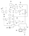
図1は第1の実施の形態による眼底カメラの構成図である。被検眼Eの前方には対物レンズ1が配置され、その後方の光路上には孔開きミラー2、この孔開きミラー2の孔に配置された撮影絞り3、蛍光撮影時に光路に挿入されるバリアフィルタ4、一部をフォーカスのために移動可能な撮影レンズ5、可動ミラー6、撮像器7が配列されている。また、可動ミラー6の反射方向にはミラー8、接眼レンズ9が配置されている。また、孔あきミラー2への照明光の入射方向には、ハロゲンランプ等の可視光を発する観察光源10、コンデンサレンズ11、蛍光撮影時に光路に挿入されるエキサイタフィルタ12、可視光の閃光を発するストロボ光源13、リング状開口を有する絞り14、レンズ15が配列されている。
【0022】
撮像器7の出力はフレームメモリを含む画像処理器21に接続され、画像処理器21はシステムコントローラ22に接続されている。システムコントローラ22には眼底カメラの左右眼スイッチ23が接続され、システムコントローラ22の出力はストロボ発光コントローラ24を介してストロボ光源13に接続されている。また、画像処理器21には入力デバイス25、表示メディアであるディスプレイ26、メモリ装置27が接続されている。なお、画像処理器21の例としてビデオキャプチャボードを内蔵したコンピュータを用いてもよい。なお、表示メディアとしてディスプレイ26の他にプリンタを付加してもよい。
【0023】
対物レンズ1、撮影絞り3、バリアフィルタ3、撮影レンズ5により、眼底撮影光学系が構成され、撮像器7と共に被検眼Eの眼底Erを撮像する眼底撮像器が構成されている。更に、可動ミラー6、ミラー8、接眼レンズ9により観察光学系が構成され、観察眼eに眼底像を提示するようになっている。更に観察光源10から穴開きミラー2の光路によって照明光学系が構成されている。
【0024】
先ず、オペレータ(撮影者又は診断者)は、撮影前に被検者のID番号、氏名、生年月目、性別等の患者情報を入力デバイス25から画像処理器21に入力する。次に、オペレータは対物レンズ1の正面に被検眼Eを位置させ、眼底撮影のためのアライメントを行う。
【0025】
観察光源10を点灯すると、その光はコンデンサレンズ11により集光され、ストロボ光源13、絞り14、レンズ15を通り、孔開きミラー2のミラー部により左方に反射され、対物レンズ1を通り被検眼Eの瞳Epを介して眼底Erを照明する。そして、観察光で照明された眼底Erの像は、再び対物レンズ1、孔開きミラー2の孔の中の撮影絞り3、撮影レンズ5を通り可動ミラー6により上方に反射され、更にミラー8により右方に反射され接眼レンズ9を介して観察眼eに達する。オペレータは眼底像を見ながら、被検眼Eと眼底カメラとの精密な位置合わせ、ピント合わせ及び撮影範囲の確認を行う。
【0026】
オペレータは撮影範囲、位置、ピント合わせが良好であることを確認した後に、図示しない撮影スイッチを操作し静止画撮影を行う。撮影スイッチの入力を検知したシステムコントローラ22は、可動ミラー6を跳ね上げて光路外に退避させると同時に、画像処理器21に撮影開始信号を出力した後に、画像処理器21からのストロボ光源13に対する発光タイミング信号を待つ。
【0027】
ここで、撮像器7と同期を取ったストロボ光源13による発光タイミング信号について説明する。ストロボ発光で静止画像を撮影する場合に、眼底像のように比較的動きの無い画像を対象とする際には、なるべくは高解像度で撮影するために、通常ではCCD等の撮像素子のフレーム蓄積モードによりテレビカメラを駆動する。
【0028】
図2に示すように、フレーム蓄積モードの場合に、1フレームは第1、第2の2つのフィールドで構成され、その各フィールド画像の光蓄積期間は、各フィールド画像出力の直前の1フレーム期間になる。つまり、2つのフィールドの蓄積期間は1フィールド分ずれている。そのため、1回のストロボ発光で1フレーム画像を取得するためには、1フレームを構成する2フィールドに共通の蓄積期間中にストロボ光源13を発光させなければならない。画像処理器21は図2のAに示すタイミングでストロボ発光をシステムコントローラ22に指示する。
【0029】
撮像器7としてCCDを用いたディジタルカメラの場合は、画像処理器21はシステムコントローラ22から撮影開始信号を受け取ると、撮像器7に対し光蓄積開始信号を出力する。同時に、システムコントローラ22に対しストロボ光源13の発光タイミング信号を出力する。
【0030】
システムコントローラ22は画像処理器21からストロボ光源13の発光タイミング信号を受け取ると、遅延なくストロボ発光コントローラ24に発光信号を送り、ストロボ光源13を発光する。ストロボ光源13から発した光束は、観察光と同様に絞り14のリング状開口を通過し、レンズ15を通り、孔開きミラー2の周辺のミラー部により左方に反射され、対物レンズ1を介して被検眼Eの瞳孔Epから眼底Erを照明する。このように照明された眼底像は、再び対物レンズ1、孔開きミラー2の孔の中の撮影絞り3、撮影レンズ5を通り、撮像器7の撮像面に結像し、撮像器7がテレビカメラの場合はテレビ信号、撮像器7がディジタルカメラの場合は画像信号となって画像処理器21に出力される。
【0031】
画像処理器21は撮像器7が出力する1フレーム分のテレビ信号又は画像信号をストロボ発光と同期をとり、フレームメモリに取り込む。続いて、画像処理器21は撮影後の撮影機器から左右眼情報等の撮影情報を読み込み、先の患者情報と合わせて、フレームメモリの撮影画像と関連付けられた付帯情報として扱う。そのとき、この付帯情報を画像データと分けてテキスト情報として扱ってもよいし、画像フォーマットのタグ領域に書き込むこともできる。なお、左右眼情報等の撮影情報は、オペレータが入力デバイス25から画像処理器21に入力することもできる。
【0032】
画像処理器21はフレームメモリの画像データを画像表示メモリに書き込む。
そのときの付帯情報の内容により、画像データを書き込む表示メモリ上のアドレスを変更する。表示メモリに書き込まれた画像データは、D/A変換後にディスプレイ26に出力される。これは撮影後に直ちに行われるため、オペレータは画像付帯情報に基づいた所定のレイアウトで表示された画像を確認しながら撮影を進めることができる。撮影後は撮影画像が直ちに表示される。
【0033】
また、画像処理器21はメモリ装置27を介して、MO、MD、DVD−RAM、VTRテープ、ハードディスク等の記憶保持可能な記録媒体Dへの書き込み又は読み出しを行う。
【0034】
付帯情報の内容により、画像メモリ上のアドレスが決定されるまでの判断例を説明すると、蛍光撮影のように同一の患者について複数枚の撮影を行う場合には、一連の撮影画像が一覧できるようにサムネイル画像で表示される。本実施例では、先の付帯情報に含まれる左右眼情報により、サムネイル画像の表示位置が決定される。
【0035】
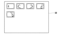
図3はディスプレイ26上のサムネイル画像の表示レイアウトを示す。画面左半分が左眼表示エリアLEFT、右半分が右眼表示エリアRIGHTとされている。左側に複数の左眼画像をサムネイル画像として提示し、右側に前記複数の左眼画像に対応する複数の右眼画像をサムネイル画像として提示している。左眼表示エリアLEFTでの変数i、右眼表示エリアRIGHTでの変数jは表示位置を示すパラメータであり、撮影開始時の初期値i、jは共に「0」である。図4はディスプレイ26上にサムネイルの眼底像が表示されている例を示している。
【0036】
図5は蛍光撮影時の判断フローチャート図を示す。蛍光タイマが起動し蛍光撮影が開始されると、先ずサムネイル画像を表示させる位置を示すパラメータのi、jが共にi=0、j=0にクリアされる。撮影後に、画像の付帯情報により左右眼を判別する。右眼の画像の場合は、jの位置にサムネイル画像を表示しパラメータjをインクリメントする。同様に、左眼の場合はiの位置にサムネイル画像を表示しパラメータiをインクリメントする。
【0037】
また、健康診断のように左右眼について各1枚撮影する場合は、ディスプレイ26の画面を2分割し、各画像を表示できる範囲で大きく表示する方法が適している。
【0038】
図6はディスプレイ26の画面上の画像表示位置を示し、画面左半分が左眼表示エリアLEFT、右半分が右眼表示エリアRIGHTである。図7はこれらのエリアに左右眼の眼底像がそれぞれ表示されている例を示している。ディスプレイ26に表示される最終的な画像は、同一のレイアウトで図示しないプリンタにプリントアウトするようにしてもよい。
【0039】
図8は第2の実施の形態の構成図であり、パノラマ撮影が可能な無散瞳眼底カメラの例を示している。これは複数の眼底撮影画像を基にパノラマ画像を表示する。図1と同一の符号は同一の部材を示している。近年行われているテレビカメラを撮影媒体に用いた撮影では、被検眼Eを照明する撮影光量が従来のフィルム撮影に比べて十分に低光量のため、無散瞳眼底カメラでも複数枚の撮影が可能である。
【0040】
ここで、照明光学系のフィルタ12の位置に、可視カットフィルタ31が挿入されている。また、ミラー8の代りにハーフミラー8’ が配置され、その反射方向にリレーレンズ32、赤外波長領域に感度を有するテレビカメラ33に配置され、テレビカメラ33の出力はディスプレイ34に接続されている。ハーフミラー8’の透過方向には眼底Erと共役にした固視灯35が配置され、被検眼Eに固視目標を提示するようにされており、この固視灯35にはシステムコントローラ22の出力が接続されている。
【0041】
固視灯35はドットマトリクス状に並んだLEDアレイ、又はLED等のバックライトとドットマトリクスの液晶シャッタにより構成され、二次元の任意の位置のドットを透過/不透過制御することにより、被検眼Eに対し任意の位置に、システムコントローラ22からの指示により固視目標を提示することができる。また、図では省略しているが、固視位置の変動がない外部固視灯を、撮影光学系と独立して固視灯として用いてもよい。
【0042】
被検眼Eの眼底Erを観察する際に、観察光源10を発した光は、可視カットフィルタ31を通過し赤外光のみにされた後は、第1の実施の形態と同様に、コンデンサレンズ11により集光され、ストロボ光源13、絞り14、レンズ15を通り、孔開きミラー2のミラ一部により左方に反射され、対物レンズ1を通り被検眼瞳Epを介して眼底Erを赤外光として照明する。
【0043】
眼底Erの像は再び対物レンズ1、孔開きミラー2の孔の中の撮影絞り3、撮影レンズ5を通り、可動ミラー6により上方に反射され、更にハーフミラー8’により左方に反射され、リレーレンズ32を通りテレビカメラ33に達する。赤外光に感度を有するテレビカメラ33は、受光した眼底像をテレビ信号に変換してディスプレイ34に出力する。
【0044】
オペレータはディスプレイ34の眼底像を見ながら、目的の撮影部位が画面中央に位置するように、固視灯35の位置を変化させて眼底撮影に必要なアライメント及びフォーカス調整を行った後に、撮影スイッチを押して撮影を行う。
【0045】
画像処理器21が画像データをフレームメモリに取り込むまでは、その動作は第1の実施の形態と同様である。続いて、画像処理器21はシステムコントローラ22から、固視灯35により被検眼Eに提示された固視目標の位置を読み取り、第1の実施の形態と同様に固視目標位置を画像の付帯情報として扱う。
【0046】
画像データの付帯情報の固視灯35の位置の変位により、画像メモリ上のアドレスが決定されるまでの判断を図9により説明する。ここで、1枚目の撮影画像は乳頭、黄斑が撮影できる位置に固視灯35を提示するのが通常であり、表示メモリの上方略中央部に画像データを書き込めばよい。2枚目の撮影画像以降は、固視灯35の提示位置を変化させた場合について説明する。
【0047】
固視灯35は眼底Erと共役位置にあり、固視灯35の提示位置により、眼底Erの黄斑の位置を誘導する。固視灯35の変位と撮影画像の部位の変位は画角を共通パラメータと考えると分かり易い。つまり変位を画角で考えると、図9(a)の固視灯35の変位(Δp,Δq)は、そのまま(b)に示す眼底画像の変位(ΔP,ΔQ)に相当する。結像倍率により画角1度当たりの表示メモリ上でのピクセル数が求まるので、画角1度を表示メモリのkピクセルに対応させて、(c)に示す表示メモリに書き込む場合を考える。
【0048】
固視灯35の提示位置を画角(Δp,Δq)相当分だけ変位させると、撮影される眼底像も画角で(ΔP,ΔQ)=(Δp,Δq)変位したことになる。従って、表示メモリ上の変位(ΔX,ΔY)は、(ΔX,ΔY)=(kΔP,kΔQ)で求めることができる。
【0049】
また、複数の眼底画像を1枚の表示メモリに書き込む場合には、輪郭のアパーチャマスクを削除して書き込むことが適している。アパーチャマスクの削除方法はここでは詳しく説明はしないが、通常ではアパーチャマスクは位置が固定しているため、フレームメモリからアパーチャマスクの位置に相当するアドレスのデータを読み飛ばす方法、画像データの輝度、色成分が、ほぼ「0」を読み飛ばす方法により達成できる。
【0050】
固視灯35の位置に基づいたレイアウトにより、撮影後直ちに表示される画像をオペレータが確認するので、撮影の取り残しがない。更に、オペレータは画像毎に撮影光量が適性であったかどうか、全体での撮影光量にばらつきはないか、フレアは入っていないか等を各画像を重ね合わせたパノラマ画像として撮影中に確認することができる。また、固視灯35の位置情報により表示メモリ上に格納する画像データのアドレスを決定する方法は、複雑な画像処理が不要なため処理時間が短時間で済む。なお、ディスプレイに表示される最終的な画像は、同一のレイアウトで図示しないプリンタにプリントアウトするようにしてもよい。
【0051】
図10はパノラマ撮影が可能な眼底カメラの第3の実施の形態の構成図である。複数の眼底撮影画像を基にパノラマ画像を表示する。図1の第1の実施の形態に対して、パンニング機構による眼底カメラ本体の位置の角度変位を検知するポテンショメータ41、チルティング機構による眼底カメラ本体の位置の角度変位を検知するポテンショメータ42の出力がシステムコントローラ22に接続されている。
【0052】
オペレータは接眼レンズ9を介して眼底像を観察しながら、目的の撮影部位が画面中央に位置するように眼底カメラ本体をチルト操作、パンニング操作及び眼底撮影に必要なアライメント及びフォーカス調整を行った後に、図示しない撮影スイッチを押して撮影を行う。画像処理器21が画像データをフレームメモリに取り込むまでは、第1の実施の形態と同様の動作がなされる。
【0053】
フレームメモリに画像を取り込んだ後に、画像処理器21はポテンショメータ41からパンニング機構による眼底カメラ本体の位置の変位、ポテンショメータ42からチルティング機構による眼底カメラ本体の位置の変位を読み取り、フレームメモリに取り込んだ画像データの付帯情報として扱う。パンニング、チルティング機構は被検眼Eの瞳孔中心を軸に行われ、眼底カメラ本体の角度変位はそのまま眼底上の角度変位に相当するため、画像データを表示メモリに書き込む位置を決定する判断は、第2の実施の形態と同様である。
【0054】
図11はディスプレイ26上に複数の撮影画像を合成したパノラマ画像のレイアウトを示している。撮影時には、それまでに合成したパノラマ画像が表示され、オペレータはそれを見て撮影部位を確認した上で撮影を行うことができる。そして、撮影した新たな部分画像は、ディスプレイ上に直ちに合成表示され、新たなパノラマ画像として表示される。ディスプレイに表示される最終的な画像は、同一のレイアウトで図示しないプリンタにプリントアウトするようにしてもよい。
【0055】
【発明の効果】
本発明に係る眼科装置によれば、ユーザビリティに優れた表示レイアウトで、撮影後に直ちに撮影画像が表示されるので、オペレータにとって直感的で極めて使い勝手の良い眼科装置が実現できる。また、撮影直後に必要な画像を撮影されたか否かが判断し易く、撮影漏れなどのミスを防ぐことができる。
【図面の簡単な説明】
【図1】第1の実施の形態の説明図である。
【図2】ストロボ露光による画像取込みタイミングの説明図である。
【図3】サムネイル表示のレイアウトの説明図である。
【図4】ディスプレイ上の眼底像表示例である。
【図5】画像表示位置を判断するフローチャート図である。
【図6】ディスプレイ上の撮影画像表示レイアウトの説明図である。
【図7】ディスプレイ上の眼底像表示の正面図である。
【図8】第2の実施の形態の構成図である。
【図9】第2の実施の形態による撮影画像表示レイアウトの説明図である。
【図10】第3の実施の形態の構成図である。
【図11】第3の実施の形態による撮影画像のパノラマ表示レイアウトの説明図である。
【図12】画像表示の従来例の説明図である。
【図13】画像表示の従来例の説明図である。
【符号の説明】
1 対物レンズ
5 撮影レンズ
6 可動ミラー
7 撮像器
10 観察光源
11 コンデンサレンズ
12 エキサイタフィルタ
13 ストロボ光源
14 絞り
15 レンズ
21 画像処理器
22 コントローラ
23 左右眼スイッチ
24 ストロボ発光コントローラ
25 入力デバイス
26、34 ディスプレイ
27 メモリ装置
33 テレビカメラ
35 固視灯
41、42 ポテンショメータ[0001]
BACKGROUND OF THE INVENTION
The present invention is, for example, relates to ophthalmic devices, such as a fundus camera and medical filing apparatus used in ophthalmic clinics and the like.
[0002]
[Prior art]
A form of managing an image of an eye to be inspected with a fundus camera as an electronic file by a personal computer with a built-in video capture board is increasing. Here, the layout for displaying the photographed image on the display is such that thumbnail images reduced in order of photographing are arranged in order as shown in FIG. 12, or one photographed image is displayed alone as shown in FIG. It is generally done.
[0003]
[Problems to be solved by the invention]
However, the above example has the following points to be improved.
[0004]
(1) In shooting methods that take multiple images of both the left and right eyes, such as during fluorescent shooting, shooting is performed while frequently changing the left and right eyes of the subject's eye during shooting, but the display is in order of shooting. There is a case where it is not readable by looking at whether the displayed image is the right eye or the left eye.
[0005]
(2) When photographing a wide range of the fundus and performing the pasting process, the operator makes a judgment by observing the image and determines the position to be pasted for each image, so that the work is very difficult.
[0006]
(3) In recent years, a criterion for photographing a plurality of parts of the same eye has been proposed for the determination of diabetic retinopathy. However, in the conventional ophthalmologic photographing apparatus, all necessary photographing parts are left to the operator. In addition, the operator is burdened, and there are problems such as insufficient imaging and multiple imaging of the same part.
[0007]
(4) A panoramic display in which the captured images can be overlaid and a wide range of parts can be listed is possible only after the imaging, and cannot be confirmed during the imaging.
[0008]
An object of the present invention is to further improve the conventional ophthalmic apparatus, and one of the specific objects is to provide an ophthalmic apparatus that achieves excellent usability by improving the display layout of the eye image displayed on the display. There is to do.
[0010]
Still other objects of the present invention will become apparent in the following detailed description.
[0011]
[Means for Solving the Problems]
To achieve the above object, the ophthalmologic apparatus according to the present invention is an image output from imaging means for imaging the eye to be examined, which is an image of either the left or right eye based on the incidental information of the image. And when the image output from the photographing means is determined to be a left-eye image by the determining means, the image output from the photographing means is displayed on the left-eye display area of the display screen. And when the image output from the imaging unit is determined to be a right-eye image by the determination unit, the image output from the imaging unit is displayed in the right-eye display area of the display screen. And processing means for displaying the plurality of images in each of the left eye display area and the right eye display area.
[0012]
Further, the ophthalmologic apparatus according to the present invention obtains the position of the screen of the display on which the image output from the photographing means for photographing the eye to be examined is based on the position of the fixation target presented to the eye to be examined. And a processing means for displaying the image at the position.
[0013]
Furthermore, the ophthalmologic apparatus according to the present invention is provided at a position of a screen of a display on which an image output from the imaging unit is displayed corresponding to a position by panning and tilting of the imaging unit for imaging the eye to be examined. It has a processing means for displaying an image.
[0021]
DETAILED DESCRIPTION OF THE INVENTION
The present invention will be described in detail based on the embodiment shown in FIGS.
FIG. 1 is a configuration diagram of a fundus camera according to the first embodiment. The
[0022]
The output of the
[0023]
The
[0024]
First, an operator (photographer or diagnostician) inputs patient information such as a subject's ID number, name, birth date, and sex from the
[0025]
When the
[0026]
After confirming that the shooting range, position, and focusing are good, the operator operates a shooting switch (not shown) to take a still image. The
[0027]
Here, a light emission timing signal by the
[0028]
As shown in FIG. 2, in the frame accumulation mode, one frame is composed of first and second fields, and the light accumulation period of each field image is one frame period immediately before each field image output. become. That is, the accumulation periods of the two fields are shifted by one field. Therefore, in order to acquire one frame image with one flash emission, the
[0029]
In the case of a digital camera using a CCD as the
[0030]
When the
[0031]
The
[0032]
The
The address on the display memory to which the image data is written is changed according to the contents of the accompanying information at that time. The image data written in the display memory is output to the
[0033]
Further, the
[0034]
An example of determination until the address on the image memory is determined according to the contents of the incidental information will be described. When a plurality of images are taken for the same patient as in fluorescence imaging, a series of captured images can be listed. Are displayed as thumbnail images. In this embodiment, the display position of the thumbnail image is determined based on the left and right eye information included in the previous incidental information.
[0035]
FIG. 3 shows a display layout of thumbnail images on the
[0036]
FIG. 5 shows a flowchart of determination at the time of fluorescent photographing. When the fluorescence timer is activated and fluorescence imaging is started, parameters i and j indicating the position for displaying the thumbnail image are first cleared to i = 0 and j = 0. After photographing, the left and right eyes are discriminated based on the accompanying information of the image. In the case of the right eye image, the thumbnail image is displayed at the position j and the parameter j is incremented. Similarly, in the case of the left eye, a thumbnail image is displayed at the position i and the parameter i is incremented.
[0037]
In addition, when taking one image for each of the left and right eyes as in a health checkup, a method of dividing the screen of the
[0038]
FIG. 6 shows the image display position on the screen of the
[0039]
FIG. 8 is a block diagram of the second embodiment, showing an example of a non-mydriatic fundus camera capable of panoramic photography. This displays a panoramic image based on a plurality of fundus images. The same reference numerals as those in FIG. 1 denote the same members. In recent photographing using a television camera as a photographing medium, the amount of photographing light for illuminating the eye E is sufficiently low compared to conventional film photographing, so even a non-mydriatic fundus camera can shoot a plurality of images. Is possible.
[0040]
Here, a
[0041]
The
[0042]
When observing the fundus Er of the eye E, the light emitted from the observation
[0043]
The image of the fundus Er passes again through the
[0044]
The operator changes the position of the
[0045]
Until the
[0046]
The determination until the address on the image memory is determined by the displacement of the position of the
[0047]
The
[0048]
If the presentation position of the
[0049]
In addition, when writing a plurality of fundus images to a single display memory, it is suitable to delete the contour aperture mask. The method for deleting the aperture mask will not be described in detail here.However, since the position of the aperture mask is usually fixed, a method of skipping the data at the address corresponding to the position of the aperture mask from the frame memory, the brightness of the image data, The color component can be achieved by a method of skipping almost “0” .
[0050]
With the layout based on the position of the
[0051]
FIG. 10 is a configuration diagram of a third embodiment of a fundus camera capable of panoramic photography. A panoramic image is displayed based on a plurality of fundus images. Compared to the first embodiment of FIG. 1, there are outputs of a
[0052]
After the operator performs tilt operation, panning operation, and alignment and focus adjustment necessary for fundus imaging so that the target imaging region is located at the center of the screen while observing the fundus image through the
[0053]
After capturing the image in the frame memory, the
[0054]
FIG. 11 shows a panoramic image layout obtained by combining a plurality of captured images on the
[0055]
【The invention's effect】
According to the ophthalmologic apparatus of the present invention, a captured image is displayed immediately after shooting with a display layout excellent in usability, so that an ophthalmic apparatus that is intuitive for the operator and extremely easy to use can be realized. In addition, it is easy to determine whether or not a necessary image has been shot immediately after shooting, and mistakes such as omission of shooting can be prevented.
[Brief description of the drawings]
FIG. 1 is an explanatory diagram of a first embodiment.
FIG. 2 is an explanatory diagram of image capture timing by strobe exposure.
FIG. 3 is an explanatory diagram of a thumbnail display layout;
FIG. 4 is a display example of a fundus image on a display.
FIG. 5 is a flowchart for determining an image display position.
FIG. 6 is an explanatory diagram of a captured image display layout on a display.
FIG. 7 is a front view of fundus image display on a display.
FIG. 8 is a configuration diagram of a second embodiment.
FIG. 9 is an explanatory diagram of a captured image display layout according to the second embodiment.
FIG. 10 is a configuration diagram of a third embodiment.
FIG. 11 is an explanatory diagram of a panorama display layout of a captured image according to the third embodiment.
FIG. 12 is an explanatory diagram of a conventional example of image display.
FIG. 13 is an explanatory diagram of a conventional example of image display.
[Explanation of symbols]
DESCRIPTION OF
Claims (2)
前記撮影手段から出力された画像が前記判別手段によって左眼の画像であると判別された場合に、前記撮影手段から出力された画像をディスプレイの画面の左眼表示エリアに表示させ、前記撮影手段から出力された画像が前記判別手段によって右眼の画像であると判別された場合に、前記撮影手段から出力された画像を前記ディスプレイの画面の右眼表示エリアに表示させる処理を行う処理手段と、を有し、前記処理手段は前記左眼表示エリア及び前記右眼表示エリアのそれぞれに複数の画像を表示させることを特徴とする眼科装置。Discriminating means for discriminating whether the image output from the imaging means for imaging the eye to be examined is an image of the left or right eye based on the incidental information of the image;
When the image output from the imaging unit is determined to be a left-eye image by the determination unit, the image output from the imaging unit is displayed in a left-eye display area of a display screen, and the imaging unit Processing means for performing processing for displaying the image output from the photographing means in the right eye display area of the display screen when the determination means determines that the image output from the imaging means is a right-eye image; And the processing means displays a plurality of images in each of the left eye display area and the right eye display area .
Priority Applications (2)
| Application Number | Priority Date | Filing Date | Title |
|---|---|---|---|
| JP2001047293A JP4731703B2 (en) | 2001-02-22 | 2001-02-22 | Ophthalmic equipment |
| US09/955,187 US20020113939A1 (en) | 2001-02-22 | 2001-09-19 | Ophthalmologic apparatus and displaying method for ophthalmic image |
Applications Claiming Priority (1)
| Application Number | Priority Date | Filing Date | Title |
|---|---|---|---|
| JP2001047293A JP4731703B2 (en) | 2001-02-22 | 2001-02-22 | Ophthalmic equipment |
Related Child Applications (1)
| Application Number | Title | Priority Date | Filing Date |
|---|---|---|---|
| JP2010256307A Division JP2011031077A (en) | 2010-11-16 | 2010-11-16 | Ophthalmologic apparatus |
Publications (3)
| Publication Number | Publication Date |
|---|---|
| JP2002238860A JP2002238860A (en) | 2002-08-27 |
| JP2002238860A5 JP2002238860A5 (en) | 2008-04-17 |
| JP4731703B2 true JP4731703B2 (en) | 2011-07-27 |
Family
ID=18908755
Family Applications (1)
| Application Number | Title | Priority Date | Filing Date |
|---|---|---|---|
| JP2001047293A Expired - Fee Related JP4731703B2 (en) | 2001-02-22 | 2001-02-22 | Ophthalmic equipment |
Country Status (2)
| Country | Link |
|---|---|
| US (1) | US20020113939A1 (en) |
| JP (1) | JP4731703B2 (en) |
Families Citing this family (8)
| Publication number | Priority date | Publication date | Assignee | Title |
|---|---|---|---|---|
| JP2002325731A (en) * | 2001-04-27 | 2002-11-12 | Nidek Co Ltd | Ophthalmic photographing device |
| JP4533028B2 (en) * | 2004-07-20 | 2010-08-25 | キヤノン株式会社 | Ophthalmic image recording apparatus, method, and program |
| JP4865257B2 (en) * | 2004-09-29 | 2012-02-01 | キヤノン株式会社 | Fundus photographing apparatus and program |
| JP5084594B2 (en) * | 2008-04-22 | 2012-11-28 | キヤノン株式会社 | Ophthalmic imaging device |
| US20150002812A1 (en) * | 2013-06-27 | 2015-01-01 | Nidek Co., Ltd. | Image processing apparatus and storage medium |
| JP6685125B2 (en) * | 2015-12-22 | 2020-04-22 | 株式会社トプコン | Ophthalmic imaging device |
| JP7304508B2 (en) * | 2019-02-19 | 2023-07-07 | 株式会社シンクアウト | Information processing system and information processing program |
| WO2021255779A1 (en) * | 2020-06-15 | 2021-12-23 | 株式会社ニコン | Information display method, information display device, and program |
Citations (7)
| Publication number | Priority date | Publication date | Assignee | Title |
|---|---|---|---|---|
| JPH06296587A (en) * | 1993-04-16 | 1994-10-25 | Shinzo Sawada | Remote monitoring system for testing eye |
| JPH06304139A (en) * | 1993-04-21 | 1994-11-01 | Canon Inc | Eye examination device |
| JPH07184863A (en) * | 1993-12-28 | 1995-07-25 | Topcon Corp | Ophthalmologic image processing system |
| JPH09173298A (en) * | 1995-12-22 | 1997-07-08 | Canon Inc | Ophthalmological camera |
| JPH10262931A (en) * | 1997-03-28 | 1998-10-06 | Topcon Corp | Ophthalmologic image processor |
| JPH11128169A (en) * | 1997-08-29 | 1999-05-18 | Topcon Corp | Optometrical device |
| JP2001014444A (en) * | 1999-06-29 | 2001-01-19 | Topcon Corp | Medical picture synthesizing processor and recording medium |
Family Cites Families (15)
| Publication number | Priority date | Publication date | Assignee | Title |
|---|---|---|---|---|
| US4715703A (en) * | 1982-10-12 | 1987-12-29 | Rodenstock Instrument Corporation | Ocular-fundus analyzer |
| US5037194A (en) * | 1988-05-31 | 1991-08-06 | Canon Kabushiki Kaisha | Ophthalmologic apparatus and method of compounding the image of an eye to be examined |
| JPH0357081A (en) * | 1989-07-26 | 1991-03-12 | Canon Inc | Picture processor |
| US5291231A (en) * | 1990-11-29 | 1994-03-01 | Kabushiki Kaisha Topcon | Opthalmological image processing system |
| JP3058680B2 (en) * | 1990-11-30 | 2000-07-04 | 株式会社トプコン | Fundus image processing device |
| DE4326716B4 (en) * | 1992-08-04 | 2005-03-03 | Kabushiki Kaisha Topcon | Arrangement for processing an ophthalmological image |
| GB9607541D0 (en) * | 1996-04-11 | 1996-06-12 | Discreet Logic Inc | Processing image data |
| JP3832895B2 (en) * | 1996-05-28 | 2006-10-11 | キヤノン株式会社 | Image composition apparatus and image composition system |
| US5993001A (en) * | 1997-06-05 | 1999-11-30 | Joslin Diabetes Center, Inc. | Stereoscopic imaging system for retinal examination with remote examination unit |
| US6097854A (en) * | 1997-08-01 | 2000-08-01 | Microsoft Corporation | Image mosaic construction system and apparatus with patch-based alignment, global block adjustment and pair-wise motion-based local warping |
| IL125483A (en) * | 1998-07-23 | 2006-08-20 | Talia Technologia Ltd | System and method for acquiring, analyzing and imaging of three dimensional retinal data |
| JP4231146B2 (en) * | 1999-04-05 | 2009-02-25 | 株式会社トプコン | Fundus camera |
| US6585374B2 (en) * | 2000-03-22 | 2003-07-01 | Canon Kabushiki Kaisha | Ophthalmologic apparatus |
| US6964025B2 (en) * | 2001-03-20 | 2005-11-08 | Microsoft Corporation | Auto thumbnail gallery |
| US20020186257A1 (en) * | 2001-06-08 | 2002-12-12 | Cadiz Jonathan J. | System and process for providing dynamic communication access and information awareness in an interactive peripheral display |
-
2001
- 2001-02-22 JP JP2001047293A patent/JP4731703B2/en not_active Expired - Fee Related
- 2001-09-19 US US09/955,187 patent/US20020113939A1/en not_active Abandoned
Patent Citations (7)
| Publication number | Priority date | Publication date | Assignee | Title |
|---|---|---|---|---|
| JPH06296587A (en) * | 1993-04-16 | 1994-10-25 | Shinzo Sawada | Remote monitoring system for testing eye |
| JPH06304139A (en) * | 1993-04-21 | 1994-11-01 | Canon Inc | Eye examination device |
| JPH07184863A (en) * | 1993-12-28 | 1995-07-25 | Topcon Corp | Ophthalmologic image processing system |
| JPH09173298A (en) * | 1995-12-22 | 1997-07-08 | Canon Inc | Ophthalmological camera |
| JPH10262931A (en) * | 1997-03-28 | 1998-10-06 | Topcon Corp | Ophthalmologic image processor |
| JPH11128169A (en) * | 1997-08-29 | 1999-05-18 | Topcon Corp | Optometrical device |
| JP2001014444A (en) * | 1999-06-29 | 2001-01-19 | Topcon Corp | Medical picture synthesizing processor and recording medium |
Also Published As
| Publication number | Publication date |
|---|---|
| US20020113939A1 (en) | 2002-08-22 |
| JP2002238860A (en) | 2002-08-27 |
Similar Documents
| Publication | Publication Date | Title |
|---|---|---|
| JP4865257B2 (en) | Fundus photographing apparatus and program | |
| JP3408308B2 (en) | Fundus camera | |
| JP4244160B2 (en) | Fundus camera | |
| US20100309431A1 (en) | Fundus camera | |
| JP2008035944A (en) | System for ophthalmologic imaging | |
| JPH05192299A (en) | Fundus camera | |
| JP4731703B2 (en) | Ophthalmic equipment | |
| JP3024790B2 (en) | Fundus camera | |
| JP5354831B2 (en) | Ophthalmic imaging equipment | |
| JP5050128B2 (en) | Image processing apparatus and method | |
| JPH1075932A (en) | Eyeground photographing device | |
| JP2003210409A (en) | Fundus camera | |
| JP5465210B2 (en) | Fundus photographing device | |
| KR100690404B1 (en) | Ophthalmologic photographing apparatus | |
| JP4570238B2 (en) | Fundus image capturing device | |
| JP5508140B2 (en) | Fundus imaging apparatus and processing method thereof | |
| JP2003230540A (en) | Ophthalmic imaging system | |
| JP2011031077A (en) | Ophthalmologic apparatus | |
| JP2005124879A (en) | Ocular fundus image processing unit | |
| JP2003204939A (en) | Ophthalmic imaging system | |
| JP4503377B2 (en) | Fundus camera | |
| JP2001258846A (en) | Ophthalmic photographic device | |
| JP3073510B2 (en) | Ophthalmic imaging equipment | |
| JP2005087301A (en) | Ophthalmologic photographing apparatus | |
| JPH07327931A (en) | Eye ground camera |
Legal Events
| Date | Code | Title | Description |
|---|---|---|---|
| A521 | Request for written amendment filed |
Free format text: JAPANESE INTERMEDIATE CODE: A523 Effective date: 20080221 |
|
| A621 | Written request for application examination |
Free format text: JAPANESE INTERMEDIATE CODE: A621 Effective date: 20080221 |
|
| A521 | Request for written amendment filed |
Free format text: JAPANESE INTERMEDIATE CODE: A523 Effective date: 20080225 |
|
| RD01 | Notification of change of attorney |
Free format text: JAPANESE INTERMEDIATE CODE: A7421 Effective date: 20100218 |
|
| RD01 | Notification of change of attorney |
Free format text: JAPANESE INTERMEDIATE CODE: A7421 Effective date: 20100630 |
|
| A977 | Report on retrieval |
Free format text: JAPANESE INTERMEDIATE CODE: A971007 Effective date: 20101014 |
|
| A131 | Notification of reasons for refusal |
Free format text: JAPANESE INTERMEDIATE CODE: A131 Effective date: 20101019 |
|
| A521 | Request for written amendment filed |
Free format text: JAPANESE INTERMEDIATE CODE: A523 Effective date: 20101116 |
|
| TRDD | Decision of grant or rejection written | ||
| A01 | Written decision to grant a patent or to grant a registration (utility model) |
Free format text: JAPANESE INTERMEDIATE CODE: A01 Effective date: 20110419 |
|
| A01 | Written decision to grant a patent or to grant a registration (utility model) |
Free format text: JAPANESE INTERMEDIATE CODE: A01 |
|
| A61 | First payment of annual fees (during grant procedure) |
Free format text: JAPANESE INTERMEDIATE CODE: A61 Effective date: 20110420 |
|
| FPAY | Renewal fee payment (event date is renewal date of database) |
Free format text: PAYMENT UNTIL: 20140428 Year of fee payment: 3 |
|
| R150 | Certificate of patent or registration of utility model |
Ref document number: 4731703 Country of ref document: JP Free format text: JAPANESE INTERMEDIATE CODE: R150 Free format text: JAPANESE INTERMEDIATE CODE: R150 |
|
| LAPS | Cancellation because of no payment of annual fees |