JP4728792B2 - IP communication apparatus, IP communication system including the same, and IP address setting method of IP communication apparatus - Google Patents
IP communication apparatus, IP communication system including the same, and IP address setting method of IP communication apparatus Download PDFInfo
- Publication number
- JP4728792B2 JP4728792B2 JP2005357599A JP2005357599A JP4728792B2 JP 4728792 B2 JP4728792 B2 JP 4728792B2 JP 2005357599 A JP2005357599 A JP 2005357599A JP 2005357599 A JP2005357599 A JP 2005357599A JP 4728792 B2 JP4728792 B2 JP 4728792B2
- Authority
- JP
- Japan
- Prior art keywords
- address
- network
- network device
- communication
- space
- Prior art date
- Legal status (The legal status is an assumption and is not a legal conclusion. Google has not performed a legal analysis and makes no representation as to the accuracy of the status listed.)
- Expired - Fee Related
Links
- 238000004891 communication Methods 0.000 title claims description 106
- 238000000034 method Methods 0.000 title claims description 21
- 238000012545 processing Methods 0.000 description 12
- 238000010586 diagram Methods 0.000 description 6
- 125000001033 ether group Chemical group 0.000 description 4
- 238000007689 inspection Methods 0.000 description 4
- 238000001514 detection method Methods 0.000 description 3
- 230000005540 biological transmission Effects 0.000 description 2
- 238000003745 diagnosis Methods 0.000 description 2
- 238000013519 translation Methods 0.000 description 2
- 238000006243 chemical reaction Methods 0.000 description 1
- 238000007796 conventional method Methods 0.000 description 1
- 238000012937 correction Methods 0.000 description 1
- 230000001934 delay Effects 0.000 description 1
- 230000000977 initiatory effect Effects 0.000 description 1
- 238000005316 response function Methods 0.000 description 1
- 238000012546 transfer Methods 0.000 description 1
Images


Classifications
-
- H—ELECTRICITY
- H04—ELECTRIC COMMUNICATION TECHNIQUE
- H04L—TRANSMISSION OF DIGITAL INFORMATION, e.g. TELEGRAPHIC COMMUNICATION
- H04L61/00—Network arrangements, protocols or services for addressing or naming
- H04L61/50—Address allocation
- H04L61/5007—Internet protocol [IP] addresses
- H04L61/5014—Internet protocol [IP] addresses using dynamic host configuration protocol [DHCP] or bootstrap protocol [BOOTP]
-
- H—ELECTRICITY
- H04—ELECTRIC COMMUNICATION TECHNIQUE
- H04L—TRANSMISSION OF DIGITAL INFORMATION, e.g. TELEGRAPHIC COMMUNICATION
- H04L61/00—Network arrangements, protocols or services for addressing or naming
- H04L61/50—Address allocation
- H04L61/5046—Resolving address allocation conflicts; Testing of addresses
-
- H—ELECTRICITY
- H04—ELECTRIC COMMUNICATION TECHNIQUE
- H04L—TRANSMISSION OF DIGITAL INFORMATION, e.g. TELEGRAPHIC COMMUNICATION
- H04L61/00—Network arrangements, protocols or services for addressing or naming
- H04L61/50—Address allocation
- H04L61/5061—Pools of addresses
Landscapes
- Engineering & Computer Science (AREA)
- Computer Networks & Wireless Communication (AREA)
- Signal Processing (AREA)
- Small-Scale Networks (AREA)
Description
本発明は、インターネットなどのIP(internet protocol)網を介して通信を行うIP通信装置およびIP通信システムならびにIP通信装置のIPアドレス設定方法に関し、特に、DHCP(Dynamic Host Configuration Protocol)サーバ機能等のルータ機能を有するIP通信装置およびこれを備えたIP通信システムならびにIP通信装置のIPアドレス設定方法に関する。 The present invention relates to an IP communication apparatus and an IP communication system that perform communication via an IP (internet protocol) network such as the Internet, and an IP address setting method of the IP communication apparatus, and in particular, a DHCP (Dynamic Host Configuration Protocol) server function and the like. The present invention relates to an IP communication device having a router function, an IP communication system including the same, and an IP address setting method for the IP communication device.
従来、IP電話装置等のIP通信装置を使用してIP網を介して通信を行う場合、それらの装置を識別するための一意な番号としてIPアドレスを割り当てておく必要がある。例えば、所定のLAN(local area network)に設けられたIP通信装置が、ルータ装置等の中継機器を介してインターネット等に接続される場合、IP通信装置のユーザ(またはネットワーク管理者)は、各装置のIPアドレスをLAN内の他の装置のIPアドレスと重複しないように手動で設定することが可能である。また、そのようなユーザの手動設定によらずに、DHCPによって自動的にIPアドレスを設定する方法が知られている。この場合、ネットワークに接続されるIP通信装置は、所定のDHCPサーバにおいて予め準備されたIPアドレスを利用することができる。このときDHCPサーバは、例えば、各装置の起動時にその要求に応じて動的にIPアドレスを割り当てる一方、通信を終えた装置のIPアドレスを回収して再び他の装置に割り当てを行うことが可能である。 Conventionally, when communication is performed via an IP network using an IP communication device such as an IP telephone device, it is necessary to assign an IP address as a unique number for identifying these devices. For example, when an IP communication device provided in a predetermined LAN (local area network) is connected to the Internet or the like via a relay device such as a router device, each user (or network administrator) of the IP communication device It is possible to manually set the IP address of the device so that it does not overlap with the IP address of other devices in the LAN. There is also known a method of automatically setting an IP address by DHCP without using such manual setting by the user. In this case, an IP communication apparatus connected to the network can use an IP address prepared in advance in a predetermined DHCP server. At this time, for example, the DHCP server dynamically assigns an IP address in response to a request at the time of starting each device, while collecting the IP address of the device that has finished communication and assigning it to another device again. It is.
ところで、上記のようにIP通信装置に割り当てられるIPアドレスは、例えば、ユーザが所定のIP通信装置に対して固定的にIPアドレスを割り当てる際に誤って他の装置と同一のIPアドレスを割り当てた場合や、既にネットワークに接続されている装置のIPアドレスと同一のIPアドレスを割り当てたIP通信装置を新たに起動した場合などにおいて、他の装置のIPアドレスと重複してしまうことがある。このようなIPアドレスの重複は、パケットの送受信が適切に行われずに通信を正常に行えなくなるというトラブルを招く可能性がある。 By the way, as for the IP address assigned to the IP communication device as described above, for example, when a user assigns a fixed IP address to a predetermined IP communication device, the same IP address as that of another device is mistakenly assigned. In some cases, or when an IP communication device that is assigned the same IP address as the IP address of a device already connected to the network is newly activated, the IP address of another device may be duplicated. Such duplication of the IP address may cause a trouble that communication cannot be normally performed without packet transmission / reception properly.
そこで、そのようなIPアドレスの重複を検出する従来技術が存在する。例えば、IPアドレス重複診断検出ホストと複数の検査対象ホストとが同一LANに接続されたネットワークシステムにおいて、IPアドレス重複診断検出ホストが、それと同一のサブネットの検査対象IPアドレスを含むARPリクエストパケットを各検査対象ホストに対してLANを介して送出し、それら各検査対象ホストからのARPリプライパケットがIPアドレス重複診断検出ホストに対してLANを介して応答されたか否かに基づいてIPアドレスの重複を検出する方法が知られている(特許文献1参照)。
しかしながら、上記特許文献1に記載のような従来技術は、IPアドレスの重複を検出すると、ユーザが手動で各装置のIPアドレスの設定を変更するなどしてその重複を解消する必要があった。また、IPアドレスの変更によって重複が一旦解消されても、上述のようなDHCPサーバを利用して各装置のIPアドレスの割り当てを実施している場合には、変更後のIPアドレスがDHCPサーバにおいて予め準備されたIPアドレスの範囲内にあると、再び同一のIPアドレスがDHCPサーバから付与されてIPアドレスの重複が生じてしまう場合があった。
However, in the related art as described in
さらに、例えば、DHCPサーバ機能などのルータ機能を備えたIP通信装置では、PC(personal computer)など複数のネットワーク機器を接続可能なLAN側のIPアドレスが属するアドレス空間が、DHCPサーバ等を利用して取得するWAN(wide area network)側のIPアドレスが属するアドレス空間と重複しないようにIPアドレスを割り当てる必要がある。 Further, for example, in an IP communication device having a router function such as a DHCP server function, an address space to which a LAN side IP address to which a plurality of network devices such as a PC (personal computer) can be connected uses a DHCP server or the like. It is necessary to assign an IP address so that it does not overlap with the address space to which the IP address on the WAN (wide area network) side to be acquired belongs.
本発明は、このような従来技術の問題点を解消するべく案出されたものであり、その第1の目的は、ユーザに煩雑な設定操作を要求することなしに、同一ネットワーク内の他の装置とのIPアドレスの重複を回避しつつ自らのIPアドレスを適切に設定することができるIP通信装置およびこれを備えたIP通信システムならびにIP通信装置のIPアドレス設定方法を提供することにある。また、本発明の第2の目的は、ユーザに煩雑な設定操作を要求することなしに、自らのWAN側のIPアドレスとのアドレス空間の重複を回避しつつ自らのLAN側のIPアドレスを適切に設定することができるIP通信装置およびこれを備えたIP通信システムならびにIP通信装置のIPアドレス設定方法を提供することにある。 The present invention has been devised to solve such problems of the prior art. The first object of the present invention is to make another setting within the same network without requiring the user to perform complicated setting operations. An object of the present invention is to provide an IP communication device capable of appropriately setting its own IP address while avoiding duplication of the IP address with the device, an IP communication system including the same, and an IP address setting method for the IP communication device. In addition, the second object of the present invention is to appropriately set the IP address on the LAN side while avoiding duplication of the address space with the IP address on the WAN side without requiring a complicated setting operation from the user. It is an object to provide an IP communication device that can be set to the above, an IP communication system including the same, and an IP address setting method for the IP communication device.
本発明のIP通信装置は、一または複数のネットワーク機器が接続され、当該ネットワーク機器のIP網を介した通信を中継するとともに、当該ネットワーク機器からの要求に応じて付与するために予め準備したリース可能なIPアドレスの範囲内から選択したIPアドレスを当該ネットワーク機器に動的に付与するIP通信装置であって、自己のLAN側のIPアドレスを設定するアドレス設定手段と、前記ネットワーク機器に対する問い合わせ結果に基づき、前記自己のIPアドレスが前記ネットワーク機器のIPアドレスと重複するか否かを判定するアドレス重複判定手段とを備え、前記アドレス設定手段は、前記自己のIPアドレスが前記ネットワーク機器のIPアドレスと重複する場合、前記自己のIPアドレスを前記予め準備したリース可能なIPアドレスの範囲外から選択したIPアドレスに変更することを特徴とする。
The IP communication apparatus according to the present invention is a lease prepared in advance for one or a plurality of network devices to be connected, relay communication of the network devices via the IP network, and be granted in response to a request from the network devices. An IP communication device that dynamically assigns an IP address selected from a range of possible IP addresses to the network device, an address setting means for setting an IP address on its own LAN side, and an inquiry result for the network device And an address duplication determination unit that determines whether or not the own IP address overlaps with the IP address of the network device, and the address setting unit includes the IP address of the network device. The IP address of the self is prepared in advance. And changing the IP address selected from the range of leasable IP address.
このように本発明によれば、他の装置の通信を中継するルータ機能を有するIP通信装置において、ユーザに煩雑な設定操作を要求することなしに、同一ネットワーク内の他の装置とのIPアドレスの重複を回避しつつ自らのIPアドレスを適切に設定することができるという優れた効果を奏する。また、他の装置の通信を中継するルータ機能を有するIP通信装置において、ユーザに煩雑な設定操作を要求することなしに、自らのWAN側のIPアドレスとのアドレス空間の重複を回避しつつ自らのLAN側のIPアドレスを適切に設定することができるという優れた効果を奏する。 As described above, according to the present invention, in an IP communication device having a router function for relaying communication of another device, an IP address with another device in the same network without requiring a complicated setting operation from the user. It is possible to appropriately set the IP address of the user while avoiding duplication. In addition, in an IP communication device having a router function for relaying communication of other devices, it avoids duplication of address space with its own WAN side IP address without requiring a complicated setting operation from the user. The LAN side IP address can be appropriately set.
上記課題を解決するためになされた第1の発明は、一または複数のネットワーク機器が接続され、当該ネットワーク機器のIP網を介した通信を中継するとともに、当該ネットワーク機器からの要求に応じて付与するために予め準備したリース可能なIPアドレスの範囲内から選択したIPアドレスを当該ネットワーク機器に動的に付与するIP通信装置であって、自己のLAN側のIPアドレスを設定するアドレス設定手段と、前記ネットワーク機器に対する問い合わせ結果に基づき、前記自己のIPアドレスが前記ネットワーク機器のIPアドレスと重複するか否かを判定するアドレス重複判定手段とを備え、前記アドレス設定手段は、前記自己のIPアドレスが前記ネットワーク機器のIPアドレスと重複する場合、前記自己のIPアドレスを前記予め準備したリース可能なIPアドレスの範囲外から選択したIPアドレスに変更する構成とする。
First invention which has been made to solve the above problems, is connected to one or more network devices, along with relays communication via the IP network of the network device in response to a request from the network device imparting An IP communication device that dynamically assigns an IP address selected from a range of leasable IP addresses prepared in advance to the network device, and an address setting unit that sets an IP address on its own LAN side ; Address duplication determining means for determining whether or not the own IP address is duplicated with the IP address of the network equipment based on a result of inquiry to the network equipment, and the address setting means includes the own IP address. Is the same as the IP address of the network device, Less the a configuration for changing the IP address selected from the outside of the leasable IP address the previously prepared.
これによると、ルータ機能を有するIP通信装置において、設定されたIPアドレスが同一LAN内の他のネットワーク機器(例えば、IP通信機能を有するPCやIP電話等)のIPアドレスと重複する場合でも、ユーザに煩雑な設定操作を要求することなしに、他のネットワーク機器とのIPアドレスの重複を回避しつつ適切なIPアドレスを設定することが可能となる。 According to this, in the IP communication device having the router function, even when the set IP address overlaps with the IP address of another network device (for example, a PC or IP phone having the IP communication function) in the same LAN, It is possible to set an appropriate IP address while avoiding duplication of IP addresses with other network devices without requiring a complicated setting operation from the user.
ここで、IPアドレスの重複が生じた場合に変更するIPアドレスは、ネットワーク機器に動的に付与するために予め準備したIPアドレス(DHCPサーバ機能によってリース可能なIPアドレス)の範囲外から選択されるので、IP通信装置のIPアドレスの変更後にネットワーク機器に対して同一のIPアドレスが新たに付与されて事後的にIPアドレス重複が生じることはない。 Here, the IP address to be changed when IP address duplication occurs is selected from outside the range of IP addresses (IP addresses that can be leased by the DHCP server function) prepared in advance to be dynamically assigned to network devices. Therefore, after the IP address of the IP communication device is changed, the same IP address is newly assigned to the network device, and there is no subsequent IP address duplication.
上記課題を解決するためになされた第2の発明は、前記アドレス設定手段は、前記変更したIPアドレスが前記ネットワーク機器のIPアドレスと重複する場合、前記変更したIPアドレスを、その属するアドレス空間内から選択した別のIPアドレスに更に変更し、一方、当該アドレス空間内の全てのIPアドレスが選択済みのときは異なるアドレス空間内から選択したIPアドレスに更に変更する構成とすることができる。
According to a second aspect of the present invention for solving the above-mentioned problem, the address setting means, when the changed IP address overlaps with the IP address of the network device, the changed IP address is stored in the address space to which the changed IP address belongs. Further, the IP address can be changed to another IP address selected, and when all the IP addresses in the address space have been selected, the IP address can be further changed to a selected IP address.
これによると、他のネットワーク機器とのIPアドレスの重複をより確実に回避することが可能となる。特に、同一アドレス空間内の全てのアドレスが、他のネットワーク機器のIPアドレスまたはネットワーク機器に動的に付与するために予め準備したIPアドレスと重複する場合であっても、変更するIPアドレスを異なるアドレス空間から容易に選択することができる。 According to this, it becomes possible to more reliably avoid duplication of IP addresses with other network devices. In particular, even when all addresses in the same address space overlap with IP addresses of other network devices or IP addresses prepared in advance for dynamically assigning to network devices, the IP addresses to be changed are different. You can easily select from the address space.
上記課題を解決するためになされた第3の発明は、一または複数のネットワーク機器が接続され、当該ネットワーク機器のIP網を介した通信を中継するとともに、当該ネットワーク機器からの要求に応じて付与するために予め準備したリース可能なIPアドレスの範囲内から選択したIPアドレスを当該ネットワーク機器に動的に付与するIP通信装置のIPアドレス設定方法であって、前記IP通信装置のLAN側のIPアドレスを設定するアドレス設定ステップと、前記ネットワーク機器に対する問い合わせ結果に基づき、前記IP通信装置のIPアドレスが前記ネットワーク機器のIPアドレスと重複するか否かを判定するアドレス重複判定ステップとを有し、前記アドレス設定ステップは、前記IP通信装置のIPアドレスが前記ネットワーク機器のIPアドレスと重複する場合、前記IP通信装置のIPアドレスを前記予め準備したリース可能なIPアドレスの範囲外から選択したIPアドレスに変更するステップを含む構成とする。
A third invention made to solve the above-described problem is that one or a plurality of network devices are connected, relays communication via the IP network of the network device, and is granted in response to a request from the network device. An IP address setting method for an IP communication device that dynamically assigns an IP address selected from a range of leasable IP addresses prepared in advance to the network device, the IP address on the LAN side of the IP communication device An address setting step for setting an address; and an address duplication determination step for determining whether or not an IP address of the IP communication device is duplicated with an IP address of the network device based on an inquiry result to the network device; In the address setting step, an IP address of the IP communication device is May overlap with the IP address of Ttowaku device, a configuration including a step of changing the IP address of the IP communication device IP address selected from the outside of the leasable IP address the previously prepared.
上記課題を解決するためになされた第4の発明は、前記アドレス設定ステップは、前記変更したIPアドレスが前記ネットワーク機器のIPアドレスと重複する場合、前記変更したIPアドレスを、その属するアドレス空間内から選択した別のIPアドレスに更に変更し、一方、当該アドレス空間内の全てのIPアドレスが選択済みのときは異なるアドレス空間内から選択したIPアドレスに更に変更するステップを含む構成とすることができる。
According to a fourth aspect of the present invention for solving the above-mentioned problems, in the address setting step, when the changed IP address overlaps with the IP address of the network device, the changed IP address is stored in the address space to which the changed IP address belongs. The IP address is further changed to another IP address selected on the other hand, and when all the IP addresses in the address space have been selected, the IP address is further changed to a selected IP address from a different address space. it can.
上記課題を解決するためになされた第5の発明は、一または複数のネットワーク機器と、前記ネットワーク機器のIP網を介した通信を中継するとともに、当該ネットワーク機器からの要求に応じて付与するために予め準備したリース可能なIPアドレスの範囲内から選択したIPアドレスを当該ネットワーク機器に動的に付与するIP通信装置とを有するIP通信システムであって、前記IP通信装置は、自己のLAN側のIPアドレスを設定するアドレス設定手段と、前記ネットワーク機器に対する問い合わせ結果に基づき、前記自己のIPアドレスが前記ネットワーク機器のIPアドレスと重複するか否かを判定するアドレス重複判定手段とを備え、前記ネットワーク機器は、自己のIPアドレスと前記IP通信装置のIPアドレスが重複する場合にのみ、前記IP通信装置からの問い合わせに応答する応答手段を備え、前記アドレス設定手段は、前記IP通信装置のIPアドレスが前記ネットワーク機器のIPアドレスと重複する場合、前記IP通信装置のIPアドレスを前記予め準備したリース可能なIPアドレスの範囲外から選択したIPアドレスに変更する構成とする。
In order to solve the above-mentioned problem, the fifth invention is to relay the communication of one or a plurality of network devices and the network devices via the IP network, and to grant them in response to a request from the network devices. the IP address selected from previously prepared within the scope of the leasable IP address an IP communication system comprising an IP communication device for dynamically given to the network equipment, the IP communication device, its own LAN side and address setting means for setting an IP address, based on the inquiry result for the network equipment, the own IP address and a determining address duplication determination unit that determines whether overlaps the IP address of the network device, wherein The network device has its own IP address and the IP address of the IP communication device. Response means for responding to an inquiry from the IP communication device only when there are multiple addresses, and the address setting means, when the IP address of the IP communication device overlaps with the IP address of the network device, configured to change the IP address to IP address selected from the outside of the leasable IP address the previously prepared.
上記課題を解決するためになされた第6の発明は、自己のWAN側のIPアドレスを所定のDHCPサーバから取得するアドレス取得手段と、前記LAN側のIPアドレスが属するアドレス空間が前記WAN側のIPアドレスが属するアドレス空間と重複するか否かを判定するWAN/LANアドレス重複判定手段とを備え、前記アドレス設定手段は、前記LAN側のIPアドレスが属するアドレス空間が前記WAN側のIPアドレスが属するアドレス空間と重複する場合、前記LAN側のIPアドレスをその属するアドレス空間とは異なるアドレス空間内から選択したIPアドレスに変更する構成とする。
A sixth invention made to solve the above-mentioned problem is that an address acquisition means for acquiring an IP address on its own WAN side from a predetermined DHCP server, and an address space to which the IP address on the LAN side belongs is on the WAN side. WAN / LAN address duplication judgment means for judging whether or not the IP address overlaps with the address space to which the IP address belongs, wherein the address setting means is configured such that the address space to which the LAN side IP address belongs is the IP address on the WAN side. When overlapping with the address space to which it belongs, the IP address on the LAN side is changed to an IP address selected from an address space different from the address space to which it belongs.
これによると、ルータ機能を有するIP通信装置において、設定されたLAN側のIPアドレスの属するアドレス空間がDHCPサーバによって付与されるWAN側のIPアドレスの属するアドレス空間と重複する場合でも、ユーザに煩雑な設定操作を要求することなしに、WAN側のIPアドレスとのIPアドレス空間の重複を回避しつつ適切なLAN側のIPアドレスを設定することが可能となる。 According to this, in an IP communication device having a router function, even if the address space to which the set LAN-side IP address belongs overlaps with the address space to which the WAN-side IP address assigned by the DHCP server belongs, it is complicated for the user. It is possible to set an appropriate IP address on the LAN side while avoiding duplication of the IP address space with the IP address on the WAN side without requiring an appropriate setting operation.
アドレス空間の重複が生じた場合には、LAN側のIPアドレス(即ち、他のネットワーク機器の接続)よりもWAN側のIPアドレス(即ち、IP通信装置自体の接続)が優先されるので、例えば、IP電話装置において通話可能な状態を安定的に維持する必要がある場合などに特に有効である。
上記課題を解決するためになされた第7の発明は、自己のWAN側のIPアドレスを所定のDHCPサーバから取得するアドレス取得ステップと、前記LAN側のIPアドレスが属するアドレス空間が前記WAN側のIPアドレスが属するアドレス空間と重複するか否かを判定するWAN/LANアドレス重複判定ステップとを有し、前記アドレス設定ステップは、前記LAN側のIPアドレスが属するアドレス空間が前記WAN側のIPアドレスが属するアドレス空間と重複する場合、前記LAN側のIPアドレスをその属するアドレス空間とは異なるアドレス空間内から選択したIPアドレスに変更するステップを含む構成とする。
If address space overlaps, the WAN side IP address (that is, the connection of the IP communication device itself) is given priority over the LAN side IP address (that is, the connection of other network devices). This is particularly effective when it is necessary to stably maintain a call-capable state in the IP telephone apparatus.
The seventh invention made to solve the above-mentioned problems is an address acquisition step of acquiring an IP address of its own WAN side from a predetermined DHCP server, and an address space to which the IP address of the LAN side belongs is on the WAN side. A WAN / LAN address duplication determination step for determining whether or not the IP address overlaps with an address space to which the IP address belongs, wherein the address setting step includes: the address space to which the LAN side IP address belongs is the IP address on the WAN side In the case of overlapping with the address space to which the IP address belongs, the IP address on the LAN side is changed to an IP address selected from an address space different from the address space to which the IP address belongs.
以下、本発明の実施の形態を、図面を参照しながら説明する。 Hereinafter, embodiments of the present invention will be described with reference to the drawings.
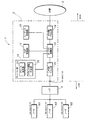
図1は、本発明の第1の実施形態に係るIP通信システムの概略を示す構成図である。このIP通信システム1は、IP網2を介した音声データの送受によって図示しない相手装置との音声通話を行うIP電話装置3と、このIP電話装置3にハブ4を介して接続されるノードN1〜N3とによって主として構成される。
FIG. 1 is a configuration diagram showing an outline of an IP communication system according to the first embodiment of the present invention. The
IP電話装置3は、ノードN1〜N3のIP網2を介した通信を中継するルータ機能を有しており、VoIP制御部11、コーデック制御部12、IP/PPP処理部13、サーバ部14、LAN側Ether部15およびWAN側Ether部16を備える。
The
VoIP制御部11は、IP網2を介して音声通話を実現するための各種制御を実行する。例えば、VoIP制御部11は、SIP(Session Initiation Protocol)に基づくIP網2上での通話制御や、音声データをリアルタイムで転送するためのRTP(Real-time Transport Protocol)に基づくデータ転送制御など行う。
The
コーデック(CODEC)制御部12は、IP網2を介して相手装置との間で送受信される音声データの符号化および復号化の制御や、音声データを通信する際の遅延や揺らぎを吸収して通話音声を安定的に再生するためのジッタバッファの制御を実行する。
The codec (CODEC)
IP/PPP処理部13は、データの伝送経路の選択やパケットサイズの変換などレイヤ3の制御を行う。
The IP /
サーバ部14は、ルータ機能を実現することでネットワーク制御を実行する。例えば、サーバ部14は、DHCP(Dynamic Host Configuration Protocol)に基づきノードN1〜N3に対するIPアドレスの割り当てや回収(DHCPサーバ機能)を実行するための制御や、NAT(Network Address Translation)またはNAPT(Network Address Port Translation)によってローカルIPアドレスが割り当てられたノードN1〜N3を透過的にIP網2にアクセス可能とするための制御を行う。
The
詳細は後述するが、サーバ部14は、IP電話装置3のLAN側のIPアドレスを設定するためのアドレス設定部21と、そのLAN側のIPアドレスがノードN1〜N3のいずれかのIPアドレスと重複するか否かを判定するアドレス重複判定部22とを有する。アドレス設定部21は、アドレス重複判定部22によってIP電話装置3のLAN側のIPアドレスがノードN1〜N3のIPアドレスと重複すると判定された場合、LAN側のIPアドレスを適当なIPアドレスに変更して当該重複を回避する。
As will be described in detail later, the
LAN側Ether部15は、LAN側のネットワークにおける電気信号の誤り訂正や再送要求などのレイヤ2の制御を実行する。同様に、WAN側Ether部16は、WAN側のネットワークにおけるレイヤ2の制御を実行する。
The LAN-
また、ノードN1〜N3は、LANに接続されるPC(personal computer)その他のIP通信機能を備えた任意のネットワーク機器を示すものであり、それらのネットワーク機器は、IP電話装置3をデフォルトゲートウェイとし、そのルータ機能を利用してIP網2を介した通信を行うことが可能である。なお、IP電話装置3に接続されるノードの数は、図1に示したものに限定されるものではなく、必要に応じて適宜変更できる。
Nodes N1 to N3 indicate a PC (personal computer) connected to the LAN or any other network device having an IP communication function. These network devices use the
IPアドレスの設定を行っていないノードN1〜N3がIP電話装置3に接続された場合、各ノードN1〜N3は、IP電話装置3のDHCPサーバ機能を利用してIPアドレス(ここでは、LANにおけるローカルIPアドレス)を取得することができる。このとき、IP電話装置3のサーバ部14は、予め準備されたリース可能なIPアドレスの中から選択したIPアドレスを各ノードN1〜N3に動的に割り当てることが可能である。
When nodes N1 to N3 for which no IP address has been set are connected to the
上記構成のIP通信システム1では、説明の便宜上、LANにおいて使用するアドレス空間(即ち、管理単位となる所定のネットワークにおけるホストアドレスの範囲)として「192.168.0.0〜192.168.0.255」(ネットマスクは、「255.255.255.0」。以下、「/24」と表す。)が予め設定されており、また、IP電話装置3のサーバ部14がノードN1〜N3に対してリース可能なIPアドレスとして「192.168.0.10〜192.168.0.50/24」が予め設定されているものとする。図1には、ノードN1に「192.168.0.10/24」、ノードN2に「192.168.0.11/24」、ノードN3に「192.168.0.12/24」がそれぞれ割り当てられた例が示されている。これらのIPアドレスは、IPv4に基づく32ビットの数値としているが、これに限らず他のプロトコル(IPv6等)を用いてIPアドレスを規定することも可能である。
In the
また、IP電話装置3のLAN側のIPアドレス(図1では、「192.168.0.1/24」)は、その初期値として、例えば、ユーザが図示しない操作キーによって手動で設定した値や工場出荷時の設定値が割り当てられている。一方、IP電話装置3のWAN側のIPアドレス(ここでは、グローバルIPアドレス)については、例えば、IP/PPP処理部13のPPPoE(Point to Point Protocol over Ethernet(登録商標))機能によってIP電話装置3がPPPoEクライアントとして動作することで、所定のISP(Internet Service Provider)等から動的に割り当てることができる。或いは、IP電話装置3のWAN側のIPアドレスとして、図示しないDHCPサーバから動的に割り当てられたIPアドレスや、ユーザが手動で設定した固定のIPアドレスを使用する構成も可能である。
Further, the IP address on the LAN side of the IP telephone apparatus 3 (“192.168.0.1/24” in FIG. 1) is, for example, a value manually set by the user using an operation key (not shown) as an initial value. And factory default values are assigned. On the other hand, for the IP address on the WAN side of the IP telephone apparatus 3 (here, the global IP address), for example, the IP telephone apparatus is configured by the PPPoE (Point to Point Protocol over Ethernet (registered trademark)) function of the IP /
上記IP電話装置3のLAN側のIPアドレスは、各ノードN1〜N3のIPアドレスとは異なる値とする必要があるが、例えば、ノードN1〜N3のIPアドレスが手動設定された場合などにおいて、その手動設定されたIPアドレスと同一の値のIPアドレスがIP電話装置3のLAN側に設定されてしまう可能性がある。そこで、IP電話装置3は、そのようなIPアドレスの重複が生じ得る装置起動時やハブ4との通信の接続時(例えば、通信ケーブルの抜けやハブ4の電源オフ等によって接続が遮断された後の再接続時)において、それらのIPアドレスの重複を判定し、重複が生じていると判定された場合には、LAN側のIPアドレスを適切な値に変更して設定を行う機能を備えている。
The IP address on the LAN side of the
次に、IP電話装置3がそのLAN側のIPアドレスの重複を回避するための動作の詳細について説明する。
Next, details of the operation for the
図2は、図1に示したIP電話装置におけるLAN側のIPアドレスの設定動作を示すフロー図である。装置起動時やハブ4との通信の接続時においてIPアドレスの設定制御が開始されると、まず、アドレス重複判定部22は、現在自IP電話装置に設定されている(或いは、設定候補となっている)LAN側のIPアドレスの値(例えば、「192.168.0.1/24」)を取得し(ST101)、各ノードN1〜N3のIPアドレスとの重複判定処理を実行する(ST102)。この重複判定処理においては、図3ついて後述するように、IP電話装置3は、各ノードN1〜N3に対してIPアドレスが重複するか否かの問合せを行い、その問い合わせ結果に基づき重複判定を行う。
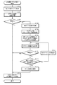
FIG. 2 is a flowchart showing the setting operation of the IP address on the LAN side in the IP telephone apparatus shown in FIG. When IP address setting control is started at the time of starting the apparatus or at the time of communication connection with the hub 4, first, the address
ST102における重複判定処理の結果、IPアドレスが重複していないと判定された場合(ST103:YES)、アドレス設定部21は、現在設定されているLAN側のIPアドレスの値を使用可能であると認識し、IP/PPP処理部13におけるネットワークスタックに設定し(ST104)、IPアドレスの設定制御は終了する。
As a result of the duplication determination process in ST102, when it is determined that the IP address is not duplicated (ST103: YES), the
一方、IPアドレスが重複していると判定された場合(ST103:NO)、アドレス設定部21は、現在設定されているLAN側のIPアドレスが属するアドレス空間の情報(例えば、「192.168.0.0〜192.168.0.255/24」)を取得する。続いて、アドレス設定部21は、サーバ部14がリース可能なIPアドレスの範囲の情報(例えば、「192.168.0.10〜192.168.0.50/24」)を取得する。そこで、アドレス設定部21は、現在設定されているLAN側のIPアドレスと同一のアドレス空間内かつサーバ部14がリース可能なIPアドレスの範囲外から一のIPアドレス(例えば、「192.168.0.2/24」)を選択し(ST107)、この選択したIPアドレスとノードN1〜N3のIPアドレスとの重複判定処理をST102と同様に実行する(ST108)。なお、ここで選択されるIPアドレスは、ブロードキャスト等の特殊な用途で使用されるアドレスは除かれる。
On the other hand, when it is determined that the IP addresses are duplicated (ST103: NO), the
ST108における重複判定処理の結果、IPアドレスが重複していないと判定された場合(ST109:YES)、ST104に進み、IPアドレスの設定制御は終了する。一方、再びIPアドレスが重複していると判定された場合(ST109:NO)、現在設定されているLAN側のIPアドレスが属するアドレス空間における全てのIPアドレスが選択済みである(即ち、現在のアドレス空間における全てのIPアドレスが、ノードN1〜N3のIPアドレスと重複する可能性がある)か否かを判定する(ST110)。そこで、現在のアドレス空間に選択可能なIPアドレスがある場合には、ST107と同様にして未だ選択されていない別のIPアドレス(例えば、「192.168.0.3/24」)を選択し(ST111)、再びST108に戻る。このようにアドレス設定部21は、IPアドレスが重複する間は、新たなIPアドレスの選択を繰り返すことになる。
As a result of the duplication determination process in ST108, when it is determined that the IP addresses are not duplicated (ST109: YES), the process proceeds to ST104, and the IP address setting control ends. On the other hand, if it is determined that the IP addresses are duplicated again (ST109: NO), all IP addresses in the address space to which the currently set IP address on the LAN side belongs have already been selected (ie, the current It is determined whether or not all IP addresses in the address space may overlap with the IP addresses of the nodes N1 to N3 (ST110). Therefore, when there is a selectable IP address in the current address space, another IP address (for example, “192.168.0.3/24”) that has not been selected is selected in the same manner as ST 107. (ST111), the process returns to ST108 again. As described above, the
最終的に、現在のアドレス空間における全てのIPアドレスが選択済みと判定された場合(ST110:YES)、アドレス設定部21は、現在のアドレス空間内を別のアドレス空間(例えば、「192.168.1.0〜192.168.1.255/24」、「10.0.0.0〜10.255.255.255/8」、「172.16.0.0〜172.16.255.255/16」等)に変更して、当該アドレス空間内における一のIPアドレスを選択する(ST112)。そこで、アドレス設定部21は、その変更されたアドレス空間内において選択されたIPアドレスの値を、ネットワークスタックに設定し(ST104)、IPアドレスの設定制御は終了する。
Finally, when it is determined that all IP addresses in the current address space have been selected (ST110: YES), the
次に、図2に示したIPアドレスの設定動作におけるIPアドレスの重複判定処理(ST102、ST108)の詳細について説明する。 Next, details of IP address duplication determination processing (ST102, ST108) in the IP address setting operation shown in FIG. 2 will be described.
図3は、図2に示したIPアドレスの設定動作における重複判定処理の詳細を示すシーケンス図である。ここでは、図1に示した場合とは異なり、ノードN2のIPアドレスが、手動で「192.168.0.1/24」に設定され、IP電話装置3のLAN側のIPアドレスと重複した場合を一例として示す。
FIG. 3 is a sequence diagram showing details of the duplication determination process in the IP address setting operation shown in FIG. Here, unlike the case shown in FIG. 1, the IP address of the node N2 is manually set to “192.168.0.1/24” and is duplicated with the IP address on the LAN side of the
重複判定処理が開始されると、アドレス重複判定部22は、各ノードN1〜N3に対してIPアドレスの重複を問い合わせるために、IP/PPP処理部13からARP(Address Resolution Protocol)リクエストメッセージをブロードキャストで送信させる。このARPリクエストメッセージは、通常は所定のIPアドレスが設定されているノードN1〜N3に対してMAC(Media Access Control)アドレスの情報を要求するために使用されるものでり、ここでは、所定のIPアドレス(即ち、当該メッセージに対して応答すべき装置のIPアドレス)として、現在のIP電話装置3のLAN側のIPアドレス情報(「192.168.0.1/24」)が付加されている。
When the duplication determination process is started, the address
各ノードN1〜N3は、IP電話装置3からARPリクエストメッセージを受信する一方、必要に応じてARPリプライメッセージを返信する応答機能を有している。これにより、各ノードN1〜N3は、自らのIPアドレスが、ARPリクエストメッセージに含まれるIPアドレスと一致する場合にのみ、自らのMACアドレスやIPアドレス等の情報を含むARPリプライメッセージを返信する。
Each of the nodes N1 to N3 has a response function of receiving an ARP request message from the
図3において、IP電話装置3からARPリクエストメッセージを受信したノードN2は、IP電話装置3に対してARPリプライメッセージを返信する。IP電話装置3は、そのARPリプライメッセージを受信することで、現在のLAN側のIPアドレスがノードN2のIPアドレスと重複していることを認識する。
In FIG. 3, the node N2 that has received the ARP request message from the
なお、IP電話装置3は、ARPリクエストメッセージを送信した後に、所定の時間が経過してもいずれのノードN1〜N3からもARPリプライメッセージを受信しない場合、LAN側のIPアドレスはノードN1〜N3のいずれのIPアドレスとも重複していないと認識する。
If the
このように、IP電話装置3は、ARPメッセージの送受により、そのLAN側のIPアドレスが各ノードN1〜N3のIPアドレスと重複するか否かを判定することができる。
In this way, the
図4は、本発明の第2の実施形態に係るIP通信システムの概略を示す構成図である。このIP通信システム101は、IP電話装置3が所定の中継機器(ここでは、ルータ装置105)を介してIP網2に接続される点において図1に示したIP通信システム1とは異なる。図4に示すIP通信システム101において、図1に示したIP通信システム1と同様の構成要素については同一の符号が付してあり、以下で特に言及しない事項についてはIP通信システム1の場合と同様である。
FIG. 4 is a configuration diagram showing an outline of an IP communication system according to the second embodiment of the present invention. This
ルータ装置105は、IP電話装置3のIP網2を介した通信を中継し、また、IP電話装置3の要求に応じてそのWAN側のIPアドレス(ここでは、ローカルIPアドレス)を動的に割り当てるDHCPサーバ機能を有している。
The
IP電話装置103は、図1に示したIP電話装置3と同様に、LAN側のIPアドレスが各ノードN1〜N3のIPアドレスと重複することを回避する機能を有する。その一方で、IP電話装置103では、LAN側のIPアドレス(例えば、「192.168.0.1/24」)が属するアドレス空間(例えば、「192.168.0.0〜192.168.0.255/24」)が、ルータ装置105によって動的に割り当てられたWAN側のIPアドレス(例えば、「192.168.0.15/25」)が属するアドレス空間(例えば、「192.168.0.0〜192.168.0.127/25」)と重複する場合が生じ得る。そこで、IP電話装置103は、そのようなLAN側のアドレス空間とWAN側のアドレス空間との重複を回避する機能を更に有する。
Similar to the
サーバ部114は、図1に示したサーバ部14と同様の機能を有しており、IP電話装置103のLAN側のIPアドレスを設定するためのアドレス設定部121と、そのLAN側のIPアドレスがIP電話装置103に接続されるノードN1〜N3のいずれかのIPアドレスと重複するか否かを判定するアドレス重複判定部122とを有する。さらに、本実施形態においては、アドレス重複判定部122は、IP電話装置103のLAN側のIPアドレスが属するアドレス空間が、ルータ装置105によって動的に割り当てられたWAN側のIPアドレスが属するアドレス空間と重複するか否かを判定する。また、アドレス設定部121は、IP電話装置103のLAN側のアドレス空間がWAN側のアドレス空間と重複する場合、LAN側のIPアドレスを当該LAN側のアドレス空間とは異なるアドレス空間内から選択したIPアドレスに変更して重複を回避する。重複の回避に際しては、IP網からの着信を可能とするため、WAN側のIPアドレスを優先してLAN側のIPアドレスの方を変更するものとする。
The
図5は、図4に示したIP電話装置におけるIPアドレスの設定動作を示すフロー図である。このIPアドレスの設定動作は、ルータ装置105によって割り当てられたWAN側のアドレスのリース期間が過ぎて再度IPアドレスを取得した場合などにおいて実行される。IPアドレスの設定制御が開始されると、まず、アドレス重複判定部122は、現在設定されている(或いは、設定候補となっている)WAN側のIPアドレスの値を取得し(ST201)、WAN側のIPアドレスが属するアドレス空間とLAN側のIPアドレスが属するアドレス空間との重複判定処理を実行する(ST202)。この場合、それらのアドレス空間は、完全に一致しない場合であっても、少なくとも一部が重複している場合には重複していると判定される。
FIG. 5 is a flowchart showing an IP address setting operation in the IP telephone apparatus shown in FIG. This IP address setting operation is executed when the WAN address assigned by the
その重複判定処理の結果としてそれらのアドレス空間が重複していないと判定された場合(ST203:YES)、アドレス設定部121は、現在設定されているWAN側のIPアドレスの値を、IP/PPP処理部13におけるネットワークスタックに設定し(ST204)、IPアドレスの設定制御は終了する。 When it is determined that the address spaces do not overlap as a result of the duplication determination process (ST203: YES), the address setting unit 121 sets the IP address value on the WAN side currently set to IP / PPP. The network stack is set in the processing unit 13 (ST204), and the IP address setting control ends.
一方、それらのアドレス空間が重複していると判定された場合(ST203:NO)、アドレス設定部121は、現在設定されているLAN側のIPアドレス(例えば、「192.168.0.1/24」)が属するアドレス空間(例えば、「192.168.0.0〜192.168.0.255」)と重複しないアドレス空間(例えば、「192.168.1.0〜192.168.1.255」)を検索し、当該アドレス空間における一のIPアドレス(例えば、「192.168.1.1/24」)をLAN側のIPアドレスとして選択する(ST205)。続いて、アドレス設定部121は、その選択されたLAN側のIPアドレスの値を、IP/PPP処理部13におけるネットワークスタックに設定し(ST206)、さらに、現在のWAN側のIPアドレスの値をネットワークスタックに設定し(ST204)、IPアドレスの設定制御は終了する。 On the other hand, when it is determined that the address spaces overlap (ST203: NO), the address setting unit 121 determines that the currently set IP address on the LAN side (for example, “192.168.0.1/ 24 ") to which the address space (for example," 192.168.0.0 to 192.168.0.0.255 ") belongs, for example," 192.168.1.0 to 192.168.8.1 ". .255 ") and one IP address in the address space (for example," 192.168.1.1/24 ") is selected as the IP address on the LAN side (ST205). Subsequently, the address setting unit 121 sets the selected LAN-side IP address value in the network stack in the IP / PPP processing unit 13 (ST206), and further sets the current WAN-side IP address value. The network stack is set (ST204), and the IP address setting control ends.
なお、ST205、ST206でIP電話装置のLAN側のIPアドレスが変更された場合、配下にあるノードN1〜N3は、IP電話装置のDHCPサーバ機能により新しいIPアドレスを配布されることになる。 When the IP address on the LAN side of the IP telephone apparatus is changed in ST205 and ST206, the subordinate nodes N1 to N3 are distributed with new IP addresses by the DHCP server function of the IP telephone apparatus.
本発明を特定の実施形態に基づいて詳細に説明したが、これらの実施形態はあくまでも例示であって本発明はこれらの実施形態によって限定されるものではない。例えば、本発明におけるIP通信装置は、上述のIP電話装置に限らず、同様のルータ機能を有する種々の装置に適用することが可能である。 Although the present invention has been described in detail based on specific embodiments, these embodiments are merely examples, and the present invention is not limited to these embodiments. For example, the IP communication device according to the present invention is not limited to the above-described IP telephone device, and can be applied to various devices having a similar router function.
本発明にかかるIP通信装置およびこれを備えたIP通信システムならびにIP通信装置のIPアドレス設定方法は、ユーザに煩雑な設定操作を要求することなしに、同一ネットワーク内の他の装置とのIPアドレスの重複を回避しつつ自らのIPアドレスを適切に設定することができ、また、ユーザに煩雑な設定操作を要求することなしに、自らのWAN側のIPアドレスとのアドレス空間の重複を回避しつつ自らのLAN側のIPアドレスを適切に設定することができるので、インターネットなどのIP網を介して通信を行うIP通信装置およびIP通信システムならびにIP通信装置のIPアドレス設定方法として有用である。 An IP communication apparatus according to the present invention, an IP communication system including the same, and an IP address setting method for the IP communication apparatus include: an IP address with another apparatus in the same network without requiring a complicated setting operation from the user; The IP address can be set appropriately while avoiding duplication of IP addresses, and address space duplication with the IP address on the WAN side can be avoided without requiring complicated setting operations from the user. However, since the IP address on its own LAN side can be set appropriately, it is useful as an IP communication apparatus and an IP communication system that perform communication via an IP network such as the Internet, and an IP address setting method for the IP communication apparatus.
1,101 IP通信システム
2 IP網
3,103 IP電話装置
14 サーバ部
21,121 アドレス設定部(アドレス設定手段)
22,122 アドレス重複判定部(アドレス重複判定手段)
N1〜N3 ノード(ネットワーク機器)
DESCRIPTION OF SYMBOLS 1,101
22, 122 Address duplication judgment section (address duplication judgment means)
N1-N3 nodes (network equipment)
Claims (7)
自己のLAN側のIPアドレスを設定するアドレス設定手段と、
前記ネットワーク機器に対する問い合わせ結果に基づき、前記自己のIPアドレスが前記ネットワーク機器のIPアドレスと重複するか否かを判定するアドレス重複判定手段とを備え、
前記アドレス設定手段は、前記自己のIPアドレスが前記ネットワーク機器のIPアドレスと重複する場合、前記自己のIPアドレスを前記予め準備したリース可能なIPアドレスの範囲外から選択したIPアドレスに変更することを特徴とするIP通信装置。 It is connected one or more network devices, along with relays communication via the IP network of the network devices, from a range of pre-prepared leasable IP addresses to impart in response to a request from the network device An IP communication device that dynamically assigns a selected IP address to the network device ,
An address setting means for setting an IP address on its own LAN side ;
An address duplication determination unit that determines whether or not the IP address of the network device overlaps with the IP address of the network device based on a result of an inquiry to the network device;
The address setting means, when the own IP address is overlapped with the IP address of the network device, changing the IP address of the self to the IP address selected from the outside of the leasable IP address the previously prepared An IP communication apparatus characterized by the above.
前記IP通信装置のLAN側のIPアドレスを設定するアドレス設定ステップと、
前記ネットワーク機器に対する問い合わせ結果に基づき、前記IP通信装置のIPアドレスが前記ネットワーク機器のIPアドレスと重複するか否かを判定するアドレス重複判定ステップと
を有し、
前記アドレス設定ステップは、前記IP通信装置のIPアドレスが前記ネットワーク機器のIPアドレスと重複する場合、前記IP通信装置のIPアドレスを前記予め準備したリース可能なIPアドレスの範囲外から選択したIPアドレスに変更するステップを含むことを特徴とするIP通信装置のIPアドレス設定方法。 It is connected one or more network devices, along with relays communication via the IP network of the network devices, from a range of pre-prepared leasable IP addresses to impart in response to a request from the network device An IP address setting method for an IP communication device that dynamically assigns a selected IP address to the network device ,
An address setting step for setting an IP address on the LAN side of the IP communication device;
An address duplication determination step of determining whether or not an IP address of the IP communication device is duplicated with an IP address of the network device based on an inquiry result to the network device;
The address setting step, the IP when the IP address of the communication device overlaps the IP address of the network device, IP address select the IP address of the IP communication device from outside the leasable IP address the previously prepared A method for setting an IP address of an IP communication device, comprising the step of:
前記ネットワーク機器のIP網を介した通信を中継するとともに、当該ネットワーク機器からの要求に応じて付与するために予め準備したリース可能なIPアドレスの範囲内から選択したIPアドレスを当該ネットワーク機器に動的に付与するIP通信装置と
を有するIP通信システムであって、
前記IP通信装置は、
自己のLAN側のIPアドレスを設定するアドレス設定手段と、
前記ネットワーク機器に対する問い合わせ結果に基づき、前記自己のIPアドレスが前記ネットワーク機器のIPアドレスと重複するか否かを判定するアドレス重複判定手段とを備え、
前記ネットワーク機器は、自己のIPアドレスと前記IP通信装置のIPアドレスが重複する場合にのみ、前記IP通信装置からの問い合わせに応答する応答手段を備え、
前記アドレス設定手段は、前記IP通信装置のIPアドレスが前記ネットワーク機器のIPアドレスと重複する場合、前記IP通信装置のIPアドレスを前記予め準備したリース可能なIPアドレスの範囲外から選択したIPアドレスに変更することを特徴とするIP通信システム。 One or more network devices;
With relays communication via the IP network of the network devices, dynamic IP addresses selected from a range of pre-prepared leasable IP addresses to impart in response to a request from the network device to the network device An IP communication system having an IP communication device to be assigned,
The IP communication device
An address setting means for setting an IP address on its own LAN side ;
An address duplication determination unit that determines whether or not the IP address of the network device overlaps with the IP address of the network device based on a result of an inquiry to the network device;
The network device includes response means for responding to an inquiry from the IP communication device only when the IP address of the network device and the IP address of the IP communication device overlap.
The address setting means, the IP when the IP address of the communication device overlaps the IP address of the network device, IP address select the IP address of the IP communication device from outside the leasable IP address the previously prepared An IP communication system characterized by changing to:
前記LAN側のIPアドレスが属するアドレス空間が前記WAN側のIPアドレスが属するアドレス空間と重複するか否かを判定するWAN/LANアドレス重複判定手段と
を備え、
前記アドレス設定手段は、前記LAN側のIPアドレスが属するアドレス空間が前記WAN側のIPアドレスが属するアドレス空間と重複する場合、前記LAN側のIPアドレスをその属するアドレス空間とは異なるアドレス空間内から選択したIPアドレスに変更することを特徴とする請求項1または請求項2に記載のIP通信装置。 Address acquisition means for acquiring the IP address of the own WAN side from a predetermined DHCP server;
WAN / LAN address duplication determination means for judging whether or not the address space to which the LAN side IP address belongs overlaps with the address space to which the WAN side IP address belongs,
When the address space to which the IP address on the LAN side belongs overlaps with the address space to which the IP address on the WAN side belongs, the address setting means determines that the IP address on the LAN side is from an address space different from the address space to which the LAN side belongs. The IP communication apparatus according to claim 1, wherein the IP communication apparatus is changed to the selected IP address.
前記LAN側のIPアドレスが属するアドレス空間が前記WAN側のIPアドレスが属するアドレス空間と重複するか否かを判定するWAN/LANアドレス重複判定ステップと
を有し、
前記アドレス設定ステップは、前記LAN側のIPアドレスが属するアドレス空間が前記WAN側のIPアドレスが属するアドレス空間と重複する場合、前記LAN側のIPアドレスをその属するアドレス空間とは異なるアドレス空間内から選択したIPアドレスに
変更するステップを含むことを特徴とする請求項3または請求項4に記載のIP通信装置のIPアドレス設定方法。 An address acquisition step of acquiring an IP address of the own WAN side from a predetermined DHCP server;
A WAN / LAN address duplication determination step for judging whether or not an address space to which the LAN side IP address belongs overlaps with an address space to which the WAN side IP address belongs,
In the address setting step, when the address space to which the IP address on the LAN side belongs overlaps with the address space to which the IP address on the WAN side belongs, the IP address on the LAN side is retrieved from an address space different from the address space to which the LAN side belongs. 5. The method for setting an IP address of an IP communication apparatus according to claim 3 , further comprising a step of changing to the selected IP address.
Priority Applications (2)
| Application Number | Priority Date | Filing Date | Title |
|---|---|---|---|
| JP2005357599A JP4728792B2 (en) | 2005-12-12 | 2005-12-12 | IP communication apparatus, IP communication system including the same, and IP address setting method of IP communication apparatus |
| US11/608,930 US8098659B2 (en) | 2005-12-12 | 2006-12-11 | Communication apparatus, communication system including the same, and method for setting IP address of communication apparatus |
Applications Claiming Priority (1)
| Application Number | Priority Date | Filing Date | Title |
|---|---|---|---|
| JP2005357599A JP4728792B2 (en) | 2005-12-12 | 2005-12-12 | IP communication apparatus, IP communication system including the same, and IP address setting method of IP communication apparatus |
Publications (3)
| Publication Number | Publication Date |
|---|---|
| JP2007166069A JP2007166069A (en) | 2007-06-28 |
| JP2007166069A5 JP2007166069A5 (en) | 2010-06-03 |
| JP4728792B2 true JP4728792B2 (en) | 2011-07-20 |
Family
ID=38139257
Family Applications (1)
| Application Number | Title | Priority Date | Filing Date |
|---|---|---|---|
| JP2005357599A Expired - Fee Related JP4728792B2 (en) | 2005-12-12 | 2005-12-12 | IP communication apparatus, IP communication system including the same, and IP address setting method of IP communication apparatus |
Country Status (2)
| Country | Link |
|---|---|
| US (1) | US8098659B2 (en) |
| JP (1) | JP4728792B2 (en) |
Families Citing this family (28)
| Publication number | Priority date | Publication date | Assignee | Title |
|---|---|---|---|---|
| US20060174314A1 (en) * | 2004-07-21 | 2006-08-03 | Jacobs Paul E | Methods and apparatus for hybrid multimedia presentations |
| CN1881924B (en) * | 2005-06-16 | 2011-05-25 | 松下电器产业株式会社 | Group communication safety distribution media recording and retaking method and device |
| US8429642B1 (en) * | 2006-06-13 | 2013-04-23 | Trend Micro Incorporated | Viral updating of software based on neighbor software information |
| JP2008131601A (en) * | 2006-11-24 | 2008-06-05 | Matsushita Electric Ind Co Ltd | Communication terminal apparatus, communication system, communication method and program |
| WO2008061364A1 (en) * | 2006-11-24 | 2008-05-29 | Imris Inc. | Sterile draping for the bore of a medical imaging system |
| JP2008259094A (en) * | 2007-04-09 | 2008-10-23 | Matsushita Electric Ind Co Ltd | Wireless lan telephone communication method and system |
| US8495224B2 (en) * | 2007-06-29 | 2013-07-23 | Apple Inc. | Network management |
| EP2023545B1 (en) * | 2007-08-08 | 2009-10-28 | PacketFront Systems AB | VLAN data framing and transmission |
| CN100495992C (en) * | 2007-08-30 | 2009-06-03 | 华为技术有限公司 | Duplicated address detection method used for address conflict and network node equipment |
| DE602007005946D1 (en) * | 2007-10-12 | 2010-05-27 | Packetfront Systems Ab | Configure routers for DHCP service requests |
| EP2048848B1 (en) | 2007-10-12 | 2013-12-18 | PacketFront Network Products AB | Optical data communications |
| JP5029381B2 (en) * | 2008-01-21 | 2012-09-19 | セイコーエプソン株式会社 | Control device for controlling setting of setting information for network device |
| US9497067B2 (en) | 2008-02-19 | 2016-11-15 | Nec Corporation | Address determination apparatus, communication system, address determination method, and program |
| JP2010028604A (en) * | 2008-07-23 | 2010-02-04 | Hitachi Kokusai Electric Inc | Network system |
| TWI387289B (en) * | 2009-02-18 | 2013-02-21 | Giga Byte Tech Co Ltd | Router and method for avoiding a domain name conflict |
| WO2010150374A1 (en) * | 2009-06-24 | 2010-12-29 | 三菱電機株式会社 | Power conversion system and communication address setting method |
| JP5338597B2 (en) * | 2009-09-29 | 2013-11-13 | ブラザー工業株式会社 | IP address determination device, terminal device, and computer program |
| KR20120113740A (en) * | 2009-11-27 | 2012-10-15 | 코닌클리즈케 필립스 일렉트로닉스 엔.브이. | Wireless network system with enhanced address conflict resolving functionality |
| JP2011124695A (en) * | 2009-12-09 | 2011-06-23 | Seiko Epson Corp | Network-connected apparatus and network connection method |
| US20120131197A1 (en) * | 2010-11-23 | 2012-05-24 | Sensormatic Electronics, LLC | Method and apparatus for automatically resolving conflicting devices on a network |
| US20130182651A1 (en) * | 2012-01-13 | 2013-07-18 | Amol Dhananjay Kelkar | Virtual Private Network Client Internet Protocol Conflict Detection |
| US8868784B2 (en) * | 2012-06-28 | 2014-10-21 | Alcatel Lucent | Sticky IP prioritization based on IP pool and subnet by DHCP |
| CN103813296B (en) * | 2012-11-14 | 2018-07-24 | 南京中兴新软件有限责任公司 | The method and device of internet protocol multimedia subsystem accessing terminal to network |
| US9143929B1 (en) * | 2012-12-14 | 2015-09-22 | Western Digital Technologies, Inc. | Methods and devices configured for IP address conflict detection and resolution upon assignment of WAN IP address |
| JP6036568B2 (en) | 2013-06-18 | 2016-11-30 | 富士ゼロックス株式会社 | Information processing apparatus and program |
| US9537819B2 (en) | 2013-09-30 | 2017-01-03 | Sonos, Inc. | Facilitating the resolution of address conflicts in a networked media playback system |
| JP5696805B1 (en) * | 2014-03-20 | 2015-04-08 | 富士ゼロックス株式会社 | Information processing apparatus and program |
| CN110475315B (en) * | 2019-08-19 | 2021-05-14 | Oppo广东移动通信有限公司 | Network connection control method and related product |
Citations (2)
| Publication number | Priority date | Publication date | Assignee | Title |
|---|---|---|---|---|
| JP2004253843A (en) * | 2003-02-18 | 2004-09-09 | Canon Inc | Information processing apparatus, method of controlling the same, and control program thereof |
| JP2005327075A (en) * | 2004-05-14 | 2005-11-24 | Matsushita Electric Ind Co Ltd | Network configuration establishment method, host apparatus corresponding to network, and target apparatus corresponding to network |
Family Cites Families (8)
| Publication number | Priority date | Publication date | Assignee | Title |
|---|---|---|---|---|
| JP3534305B2 (en) * | 2000-02-29 | 2004-06-07 | 日本電気株式会社 | IP address duplication detection method using address resolution protocol |
| US6957276B1 (en) * | 2000-10-23 | 2005-10-18 | Microsoft Corporation | System and method of assigning and reclaiming static addresses through the dynamic host configuration protocol |
| JP4567233B2 (en) * | 2001-04-26 | 2010-10-20 | 富士通株式会社 | COMMUNICATION DEVICE AND ITS CONTROL METHOD |
| US7185079B1 (en) * | 2001-08-08 | 2007-02-27 | Cisco Technology, Inc. | Automated management of network addresses in a broadband managed access environment |
| US7440440B1 (en) * | 2003-12-12 | 2008-10-21 | 3Com Corporation | Method and system for device-based call park and pick-up |
| US20060221955A1 (en) * | 2005-04-05 | 2006-10-05 | Mark Enright | IP addressing in joined private networks |
| US7633855B2 (en) * | 2005-11-03 | 2009-12-15 | Cisco Technology, Inc. | System and method for resolving address conflicts in a network |
| US20070248098A1 (en) * | 2006-04-23 | 2007-10-25 | Essence Technology . Solution, Inc. | Device and method of multi-service IP-phone |
-
2005
- 2005-12-12 JP JP2005357599A patent/JP4728792B2/en not_active Expired - Fee Related
-
2006
- 2006-12-11 US US11/608,930 patent/US8098659B2/en not_active Expired - Fee Related
Patent Citations (2)
| Publication number | Priority date | Publication date | Assignee | Title |
|---|---|---|---|---|
| JP2004253843A (en) * | 2003-02-18 | 2004-09-09 | Canon Inc | Information processing apparatus, method of controlling the same, and control program thereof |
| JP2005327075A (en) * | 2004-05-14 | 2005-11-24 | Matsushita Electric Ind Co Ltd | Network configuration establishment method, host apparatus corresponding to network, and target apparatus corresponding to network |
Also Published As
| Publication number | Publication date |
|---|---|
| US20070133544A1 (en) | 2007-06-14 |
| US8098659B2 (en) | 2012-01-17 |
| JP2007166069A (en) | 2007-06-28 |
Similar Documents
| Publication | Publication Date | Title |
|---|---|---|
| JP4728792B2 (en) | IP communication apparatus, IP communication system including the same, and IP address setting method of IP communication apparatus | |
| EP2055046B1 (en) | Method and device for identifying and selecting an interface to access a network | |
| JP4723653B2 (en) | IP address assignment method and use thereof | |
| US6768743B1 (en) | Method and system for address server redirection for multiple address networks | |
| EP2364543B1 (en) | Broadband network access | |
| US7010585B2 (en) | DNS server, DHCP server, terminal and communication system | |
| EP2645679B1 (en) | Method and apparatus for message transmission | |
| US9191362B2 (en) | Determining the type of upstream network address translation from a home gateway | |
| JP2007520970A (en) | Tunneling service method and system | |
| WO2009117963A1 (en) | Address configuring method, apparatus and system | |
| KR20160131935A (en) | Method for allocating internet protocol addresses to clients of a network and corresponding apparatus | |
| JP2006086800A (en) | Communication apparatus for selecting source address | |
| JP6558492B2 (en) | Network address translation device, setting request device, communication system, communication method, and program | |
| US9497067B2 (en) | Address determination apparatus, communication system, address determination method, and program | |
| WO2015127751A1 (en) | Method for processing nat64 prefix, network device and dhcpv6 server | |
| WO2008011776A1 (en) | An address assignment realizing method and the system, the relay agent, the server thereof | |
| JP2002217941A (en) | Network address reallocating method and router | |
| US7085836B1 (en) | System and method for automatic private IP address selection | |
| JP2007081456A (en) | Converter | |
| JP2008227663A (en) | Ip communication device, ip communication system equipped with the same, and ip address setting method | |
| WO2015139397A1 (en) | Nat64 resource acquisition method and acquisition/distribution apparatus | |
| JP3589445B2 (en) | Method and apparatus for setting network address | |
| JP2010157857A (en) | Vpn connection device, packet control method, and program | |
| KR102340268B1 (en) | Method and apparatus for recognizing the network environment and determining the operation mode automatically in a home gateway | |
| JP4289075B2 (en) | Aggregate address space allocation method and system for ARCP |
Legal Events
| Date | Code | Title | Description |
|---|---|---|---|
| A621 | Written request for application examination |
Free format text: JAPANESE INTERMEDIATE CODE: A621 Effective date: 20080930 |
|
| A521 | Request for written amendment filed |
Free format text: JAPANESE INTERMEDIATE CODE: A523 Effective date: 20100419 |
|
| A131 | Notification of reasons for refusal |
Free format text: JAPANESE INTERMEDIATE CODE: A131 Effective date: 20101124 |
|
| A521 | Request for written amendment filed |
Free format text: JAPANESE INTERMEDIATE CODE: A523 Effective date: 20110112 |
|
| TRDD | Decision of grant or rejection written | ||
| A01 | Written decision to grant a patent or to grant a registration (utility model) |
Free format text: JAPANESE INTERMEDIATE CODE: A01 Effective date: 20110329 |
|
| A61 | First payment of annual fees (during grant procedure) |
Free format text: JAPANESE INTERMEDIATE CODE: A61 Effective date: 20110415 |
|
| R150 | Certificate of patent or registration of utility model |
Free format text: JAPANESE INTERMEDIATE CODE: R150 Ref document number: 4728792 Country of ref document: JP Free format text: JAPANESE INTERMEDIATE CODE: R150 |
|
| FPAY | Renewal fee payment (event date is renewal date of database) |
Free format text: PAYMENT UNTIL: 20140422 Year of fee payment: 3 |
|
| LAPS | Cancellation because of no payment of annual fees |