JP4728560B2 - Electrosurgical electrode - Google Patents
Electrosurgical electrode Download PDFInfo
- Publication number
- JP4728560B2 JP4728560B2 JP2002560716A JP2002560716A JP4728560B2 JP 4728560 B2 JP4728560 B2 JP 4728560B2 JP 2002560716 A JP2002560716 A JP 2002560716A JP 2002560716 A JP2002560716 A JP 2002560716A JP 4728560 B2 JP4728560 B2 JP 4728560B2
- Authority
- JP
- Japan
- Prior art keywords
- electrosurgical electrode
- electrode
- electrosurgical
- patient
- pad
- Prior art date
- Legal status (The legal status is an assumption and is not a legal conclusion. Google has not performed a legal analysis and makes no representation as to the accuracy of the status listed.)
- Expired - Lifetime
Links
Images


Classifications
-
- A—HUMAN NECESSITIES
- A61—MEDICAL OR VETERINARY SCIENCE; HYGIENE
- A61B—DIAGNOSIS; SURGERY; IDENTIFICATION
- A61B18/00—Surgical instruments, devices or methods for transferring non-mechanical forms of energy to or from the body
- A61B18/04—Surgical instruments, devices or methods for transferring non-mechanical forms of energy to or from the body by heating
- A61B18/12—Surgical instruments, devices or methods for transferring non-mechanical forms of energy to or from the body by heating by passing a current through the tissue to be heated, e.g. high-frequency current
- A61B18/14—Probes or electrodes therefor
- A61B18/16—Indifferent or passive electrodes for grounding
-
- A—HUMAN NECESSITIES
- A61—MEDICAL OR VETERINARY SCIENCE; HYGIENE
- A61B—DIAGNOSIS; SURGERY; IDENTIFICATION
- A61B50/00—Containers, covers, furniture or holders specially adapted for surgical or diagnostic appliances or instruments, e.g. sterile covers
- A61B50/10—Furniture specially adapted for surgical or diagnostic appliances or instruments
- A61B50/13—Trolleys, e.g. carts
-
- A—HUMAN NECESSITIES
- A61—MEDICAL OR VETERINARY SCIENCE; HYGIENE
- A61B—DIAGNOSIS; SURGERY; IDENTIFICATION
- A61B18/00—Surgical instruments, devices or methods for transferring non-mechanical forms of energy to or from the body
- A61B2018/00005—Cooling or heating of the probe or tissue immediately surrounding the probe
- A61B2018/00011—Cooling or heating of the probe or tissue immediately surrounding the probe with fluids
- A61B2018/00023—Cooling or heating of the probe or tissue immediately surrounding the probe with fluids closed, i.e. without wound contact by the fluid
-
- A—HUMAN NECESSITIES
- A61—MEDICAL OR VETERINARY SCIENCE; HYGIENE
- A61B—DIAGNOSIS; SURGERY; IDENTIFICATION
- A61B18/00—Surgical instruments, devices or methods for transferring non-mechanical forms of energy to or from the body
- A61B18/04—Surgical instruments, devices or methods for transferring non-mechanical forms of energy to or from the body by heating
- A61B18/12—Surgical instruments, devices or methods for transferring non-mechanical forms of energy to or from the body by heating by passing a current through the tissue to be heated, e.g. high-frequency current
- A61B18/14—Probes or electrodes therefor
- A61B18/16—Indifferent or passive electrodes for grounding
- A61B2018/167—Passive electrodes capacitively coupled to the skin
-
- A—HUMAN NECESSITIES
- A61—MEDICAL OR VETERINARY SCIENCE; HYGIENE
- A61B—DIAGNOSIS; SURGERY; IDENTIFICATION
- A61B90/00—Instruments, implements or accessories specially adapted for surgery or diagnosis and not covered by any of the groups A61B1/00 - A61B50/00, e.g. for luxation treatment or for protecting wound edges
- A61B90/08—Accessories or related features not otherwise provided for
- A61B2090/0813—Accessories designed for easy sterilising, i.e. re-usable
-
- A—HUMAN NECESSITIES
- A61—MEDICAL OR VETERINARY SCIENCE; HYGIENE
- A61B—DIAGNOSIS; SURGERY; IDENTIFICATION
- A61B46/00—Surgical drapes
- A61B46/10—Surgical drapes specially adapted for instruments, e.g. microscopes
-
- A—HUMAN NECESSITIES
- A61—MEDICAL OR VETERINARY SCIENCE; HYGIENE
- A61B—DIAGNOSIS; SURGERY; IDENTIFICATION
- A61B46/00—Surgical drapes
- A61B46/40—Drape material, e.g. laminates; Manufacture thereof
-
- A—HUMAN NECESSITIES
- A61—MEDICAL OR VETERINARY SCIENCE; HYGIENE
- A61F—FILTERS IMPLANTABLE INTO BLOOD VESSELS; PROSTHESES; DEVICES PROVIDING PATENCY TO, OR PREVENTING COLLAPSING OF, TUBULAR STRUCTURES OF THE BODY, e.g. STENTS; ORTHOPAEDIC, NURSING OR CONTRACEPTIVE DEVICES; FOMENTATION; TREATMENT OR PROTECTION OF EYES OR EARS; BANDAGES, DRESSINGS OR ABSORBENT PADS; FIRST-AID KITS
- A61F7/00—Heating or cooling appliances for medical or therapeutic treatment of the human body
- A61F2007/0054—Heating or cooling appliances for medical or therapeutic treatment of the human body with a closed fluid circuit, e.g. hot water
-
- A—HUMAN NECESSITIES
- A61—MEDICAL OR VETERINARY SCIENCE; HYGIENE
- A61F—FILTERS IMPLANTABLE INTO BLOOD VESSELS; PROSTHESES; DEVICES PROVIDING PATENCY TO, OR PREVENTING COLLAPSING OF, TUBULAR STRUCTURES OF THE BODY, e.g. STENTS; ORTHOPAEDIC, NURSING OR CONTRACEPTIVE DEVICES; FOMENTATION; TREATMENT OR PROTECTION OF EYES OR EARS; BANDAGES, DRESSINGS OR ABSORBENT PADS; FIRST-AID KITS
- A61F7/00—Heating or cooling appliances for medical or therapeutic treatment of the human body
- A61F7/02—Compresses or poultices for effecting heating or cooling
-
- Y—GENERAL TAGGING OF NEW TECHNOLOGICAL DEVELOPMENTS; GENERAL TAGGING OF CROSS-SECTIONAL TECHNOLOGIES SPANNING OVER SEVERAL SECTIONS OF THE IPC; TECHNICAL SUBJECTS COVERED BY FORMER USPC CROSS-REFERENCE ART COLLECTIONS [XRACs] AND DIGESTS
- Y10—TECHNICAL SUBJECTS COVERED BY FORMER USPC
- Y10S—TECHNICAL SUBJECTS COVERED BY FORMER USPC CROSS-REFERENCE ART COLLECTIONS [XRACs] AND DIGESTS
- Y10S128/00—Surgery
- Y10S128/908—Patient protection from electric shock
Landscapes
- Health & Medical Sciences (AREA)
- Surgery (AREA)
- Life Sciences & Earth Sciences (AREA)
- Engineering & Computer Science (AREA)
- Biomedical Technology (AREA)
- Public Health (AREA)
- Nuclear Medicine, Radiotherapy & Molecular Imaging (AREA)
- Veterinary Medicine (AREA)
- General Health & Medical Sciences (AREA)
- Heart & Thoracic Surgery (AREA)
- Medical Informatics (AREA)
- Molecular Biology (AREA)
- Animal Behavior & Ethology (AREA)
- Physics & Mathematics (AREA)
- Otolaryngology (AREA)
- Plasma & Fusion (AREA)
- Surgical Instruments (AREA)
- Artificial Filaments (AREA)
- Accommodation For Nursing Or Treatment Tables (AREA)
Description
【0001】
(発明の背景)
(発明の分野)
本発明は、電気外科電極上に載る患者に対して褥瘡の発症を防止するための電気外科電極に関し、特に、電気外科パッドと褥瘡(pressure sore;床擦れ)パッドの両方に関する。より詳細には、褥瘡性潰瘍(decubitus ulcer)又は褥瘡(pressure sore)の発症が最小となるように患者の身体に適合するとともに、導電性ゲル又は誘電体ゲルを必要とせずに効果的かつ安全な電気外科エネルギーリターンとして動作することができる褥瘡パッドに関する。
【0002】
(関連技術)
患者が長期間固定されている間、褥瘡としても知られる褥瘡性潰瘍を発症する可能性があることは、医学分野で周知である。一般に褥瘡は、寝たきりになっている、または動きが限定されている高齢の患者に発症する。褥瘡は、長期にわたって患者の組織に圧力が加えられる患者の身体領域、通常は下になる、骨が隆起している領域で発症する。この長期にわたる圧力により、正常毛細管圧32mmHgを超える血圧が維持されるために、虚血性の損傷および組織の壊死が引き起こされる。褥瘡は通常、長期にわたってある姿勢のままでいる患者に発症するが、様々な外科処置の間などの短い期間、約2時間にわたって、局所的な領域に強い圧力が加えられることによって発症する可能性もある。
【0003】
一般に、褥瘡を防止するには、患者の姿勢を頻繁に変更して患者の組織を緩和させる。加えて、下になる、骨の隆起を覆う組織などの患者の身体の敏感な領域に加えられる圧力を低減する、フォームパッド、羊皮層、空気充填マットレス、ウォーターマットレスなどの様々なマットレスまたはパッドのうちの1つに患者が載せられることがある。圧力を低減するマットレスまたはパッド上に患者が載っているかどうかに関わらず、2時間ごとに患者の姿勢を変更することが望ましいが、電気外科処置など様々な外科処置中にはこれを行うのが難しいことがしばしばある。
【0004】
電気外科処置中には、組織を切断し、外科処置を実行する際に遭遇する出血を凝固させるために、無線周波数(RF)出力が利用される。このような技法の歴史的な観点および詳細については、D′Amelio他の「Electrosurgical Probe Apparatus」の米国特許第4936842号明細書に具体的に開示されているので参照されたい。
【0005】
医学分野の技術者にとって周知であるように、電気外科療法は広範に使用されており、切断と凝固のどちらに対しても単一の外科器具を使用することを含む、多くの利点がもたらされる。しかし、あらゆる単極電気外科発電器システムは、外科手術を行う手術室で外科医によって患者に印加される活性電極と、患者から発電器に戻るリターンパス(return path)とを有さなければならない。患者との接点での活性電極は、高電流密度を生成し、組織を切断または凝固する外科的効果を生み出すために小サイズでなければならない。活性電極と同じ電流を搬送するリターン電極(return electrode)は、低密度電流が患者からリターン電極に流れるように、患者との伝達点で十分大きい実効表面積を有さなければならない。比較的高い電流密度がリターン電極で生成される場合、患者の皮膚および組織の温度がこの領域で上昇し、望ましくない患者の熱傷が生じる可能性がある。周知の医学検査機関の緊急医療研究会によると、壊死の閾値に至るまでの体組織の加熱は、電流密度が100ミリアンペア/cm2を超過したときに発生する。さらに、医療器具開発協会(「AAMI」)は、電気外科リターン電極に隣接する最大患者表面組織温度が指定のテスト条件下で摂氏6度(6°)よりも上昇してはならないことを要求する規格を発表した。
【0006】
過去20年にわたって、産業界は、より安全なリターン電極に対する医療上の必要に応えて、主に2つの方法で製品を開発してきた。まず、患者の臀部、大腿、肩、または重力によって十分な接触領域を保証することができる任意の位置の下に配置された、約12×7インチ(約30×18cm)の小型の導電性ゲルで被覆された平坦なステンレス鋼板から、柔軟な電極に変更された。この柔軟な電極は、一般にステンレス鋼板とほぼ同サイズのものであり、導電性ポリマーまたは誘電体ポリマーで被覆され、かつその上に、重力がなくても患者に取り付けておくように粘着性の縁を有する。電気外科処置の完了時に、この平坦で柔軟な電極は処分される。1980年代の初期までには、米国のほとんどの病院は、このタイプのリターン電極に切り換えた。このリターン電極は、旧型の鋼板より優れており、患者のリターン電極による熱傷が減少したが、このリターン電極により米国では、毎年数千万ドルの追加の外科的な費用がかかることになった。この改良品を用いても、依然として病院では、誤って落とされる電極、または手術中に患者から部分的に分離される電極によって患者の熱傷が生じている。
【0007】
その後、患者と接触している電極の接触領域を監視し、不十分な接触領域があるときはいつでも電気手術発電器をオフにする、さらに改良された電極接触品質監視システムが提案された。このような回路についは、例えば、Newton「Safety Monitoring Circuit for Electrosurgical Unit」の米国特許第4231372号明細書に記載されている。このシステムにより、患者のリターン電極熱傷がさらに減少したが、このシステムは、特別な使い捨て電極と発電器に追加の回路を必要とし、処置あたりのコストがずっと高価になる。このシステムが最初に発表されてから15年後には、このシステムが高コストであるために、このシステムが使用されたのは米国で実施された全外科手術の40パーセント未満であった。
【0008】
先に論じたように電気外科の分野で様々な進歩があったものの、電気外科的処置中、および他の外科的処置中に褥瘡の発症を防止することに関連する問題が依然として残っている。
【0009】
上述したように、一般には、外科的処置中、患者は、組織が下になる、骨の隆起を覆っているところの身体の敏感な領域に加えられる力を低減または実質上解消するために、減圧マットレスまたは減圧パッドの上に置かれる。手術の状況で褥瘡を防止するのに使用することができる1つの装置は、手術台と患者との間に配置される、高さ約3〜4インチ(約8〜10cm)のフォームパッドである。フォームパッドは安価で軽量であることなど多くの利点を有するが、患者が得られる緩和は最小であり、それとともに褥瘡の生成を助長する可能性のある体熱を閉じ込めてしまう。さらにフォームパッドは、熱を閉じ込めることによって患者の組織温度の上昇を助長する可能性があり、その結果、電気外科処置中に組織温度がAAMIによって要求されている摂氏6度(6°)の温度上昇を超えて上昇する可能性がある。加えて、フォームパッドは滅菌および浄化が難しいので、一般に外科的処置の後に廃棄される。さらに、フォームパッドを形成する材料は、燃焼中に致死的なガスを放出する可能性がある。
【0010】
代替の減圧マットレスまたは減圧パッドは、手術台上に配置された羊皮の層である。遺憾ながら、羊皮によって実現される患者に対する保護は不十分であり、患者の圧力は、患者が載っている面全体にわたって効率的に分散されない。上述したフォームパッドと同じく、羊皮は、外科的処置に続いて滅菌および浄化するのが難しい。
【0011】
さらに別のタイプの減圧装置は、所望の圧力まで空気を充填したビニルスリーブを含む空気膨張マットレスである。遺憾ながら、マットレスが配置される底面に患者が触れるのを防止するために、空気マットレスをかなり加圧しなければならない。患者が底面に触れる場合、褥瘡が発症する可能性がある。加えて、必要な圧力を維持するためには、一般にポンプをマットレスに接続して、マットレス内に含まれる空気の圧力を監視し、必要に応じて追加の空気をマットレス内に注入する。可動空気マットレス上に置かれ、手術台上に載っている患者の場合、患者は2つの柔軟な表面上に置かれている。それによってこの患者は、外科的処置中に不安定かつ危険な位置に置かれる。加えて空気タイプマットレスは、必要な空気圧を維持するためのポンプが必要であるので、維持するのに費用がかかる。さらに、空気マットレスは容易に穴があきやすく、それによって空気が漏れ、マットレスが配置される表面から患者を離しておくというマットレスの有効性が低下する。
【0012】
空気充填マットレスと類似の圧力低減装置は、ウォータタイプマットレスである。ウォータタイプマットレスは空気マットレスと類似の形を有する。しかし、空気ではなく、水がマットレスに注入される。遺憾ながらウォータタイプマットレスも、空気タイプマットレスに課される制限の多くを受ける。加えて、ウォーターマットレスが漏れた場合、大量の水が患者の周囲の床に放出され、それによって歩行することが危険となり、患者の近くで作業することが危険となる。
【0013】
上述した制限の多くは、病院内で一般的に使用する上では緩和されるが、列挙した各褥瘡装置は、電気外科処置中に使用することに関して様々な欠点を有する。例えば、フォームタイプマットレスを電気外科処置中に使用する場合、フォームパッドに着火する可能性があり、それによって患者が熱傷を負い、さらには手術室内に致死的なガスが放出される可能性もある。
【0014】
空気タイプマットレスやウォータタイプマットレスに関しては、長期間にわたって所望の圧力を維持するのに必要なポンプを含めることにより、手術室内に格納する必要のある装置の量が増大する。したがって、限られたスペース内に多くの装置があると、外科医が移動しにくくなる。ウォーターマットレスから水が漏れた場合、電気外科リターン電極が短絡する可能性があるだけではなく、手術室内の患者、および/または医師および看護士が感電死する可能性もある。
【0015】
したがって、褥瘡の発症を低減すると同時に自己規制型である電気外科電極を提供することは、現在の電気外科技術における進歩となることになる。
【0016】
(発明の概要)
本発明は、高価な使い捨て電極や、特別なRF発電器内の監視回路の必要なしに、患者の熱傷をなくするリターン電極を提供し、同時に電気外科処置を有する患者の褥瘡の発症を最小にする褥瘡パッドも提供することによって従来技術の問題点を解決することである。
【0017】
すなわち、本発明の好ましい実施形態による改良型のリターン電極は、これまでに開示され、または手術で使用された他のリターン電極よりも大きい実効表面積を含むものである。この有効表面積は大きく、かつ患者の身体に対して位置決めされるように適合されているので、導電性ゲルまたは誘電体ゲルの必要がなくなる。さらに、露出表面は、容易に洗浄可能、殺菌可能、かつ/または消毒可能な材料で作られ、それによって繰り返し再利用するために調整することが容易かつ迅速となる。露出表面では、電極の作用表面の実効領域が普通なら望ましいレベル未満に減少する場合に、一般に使用される電気外科周波数でのインピーダンス特性が電流密度(および対応する温度上昇)を安全な閾値に自己規制するような幾何形状および材料が使用される。したがって、上述した特別なRF発電器内の高価な監視回路が不要となる。さらに、この改良型のリターン電極は、患者とリターン電極間の電流移送の助けとなるとともに、褥瘡の形成を防止する褥瘡パッドを組み込んだものである。
【0018】
本発明の上述した利点及び特徴、並びに他の利点及び特徴が得られるように、これまで簡潔に述べてきた本発明のより具体的な説明を、添付した図面に示されている本発明の特定の実施形態を参照しながら行う。これらの図面は単に本発明の代表的な実施形態を示したものであって、この実施形態によって、本発明の技術的な範囲を限定するものでないことを踏まえて、添付した図面に基づいて本発明をより具体的かつ詳細に説明する。
【0019】
(発明の詳細な説明)
本発明の様々な態様、具体的な実施形態、および特徴を理解する助けとなるように、まず、単体で、あるいは褥瘡パッドと組み合わせて使用することができる自己規制型電気外科電極の新規な構造および特徴について説明する。このような説明に続いて、本発明のこの新規な褥瘡パッドの様々な具体的な実施形態について説明する。電気外科電極が一体的に形成された褥瘡パッドにより、1つの装置が、限定はしないが電気外科処置を含む様々な外科的処置中に褥瘡が発症することを防止する褥瘡パッドの減圧特性を組み込むとともに、電気外科処置に必要な自己規制特性も含むことが可能となる。このようにして、本発明のこの新規な電気外科電極は、電気外科処置中の熱傷から患者を保護し、褥瘡が発症することを阻止する。
【0020】
次に、図1には、手術中に電気手術発電器に与えられる無線周波数電流の動作経路中に実質上含まれる典型的なインピーダンスを示す、簡略化した電気構成図が示されている。図1には、限定はしないが一定の電力、電圧、および/または電流、あるいは可変の電力、電圧、および/または電流などの従来型無線周波数発電器10が示されている。従来型の導線11および12が発電器10に接続され、それぞれ、インピーダンスz1によって表される外科医の器具と、インピーダンスz3によって表される電気外科リターン電極とに発電器10を接続する。手術部位とリターン電極との間に存在する患者の組織によって与えられるインピーダンスを表すため、インピーダンスz2を与える。導線11および12は、シートに対して電気的接続を行う接続手段の機能を果たすことができる1つの例示的構造を表す。しかし、他の様々な構造も適切であり、所望の機能を果たすことができることを当業者は理解されたい。
【0021】
図1は、簡略化した回路図であり、手術器具、患者の身体、およびリターン電極によって与えられるリアクタントを含む主要な抵抗の点から回路要素を一般に考慮し、それによって本発明の原理をはっきりと、かつ簡潔に示すようにしているが、実際には、分布インダクタンスおよび分布キャパシタンスなど、ある種の他のパラメータも発生する。このパラメータは、本明細書の原理の例示をわかりやすくするために比較的小さいと見なし、この説明のこの時点では考慮しない。しかし、以下で述べるように、電極と患者の身体との間に絶縁スリーブを置くときの一実施形態では、容量性リアクタンスのかなりの要素がz3のインピーダンス内に含まれる可能性がある。本発明の原理を簡潔に提示するように、図1〜図10は意図的に簡略化してあり、より厳密かつ完全な説明を図11〜図17に関連して提示していることにも留意されたい。
【0022】
本明細書の最初の実施形態は、組合せ抵抗性モードおよび/または容量性モードで動作する電極の実施形態である。したがって、比較的小さい漂遊容量性リアクタントおよび誘導性リアクタントを無視した場合、回路の合計実効インピーダンスは、個々のインピーダンスz1、z2、およびz3の和に等しくなり、本質的に同じ電流がこの3つすべてを通過するので、RF発電器10によって生成される電圧は、インピーダンスz1、z2、およびz3にわたって、それぞれの値に正比例して分布することになる。したがって、このような各成分内に解放されるエネルギーもまた、その値に正比例することになる。
【0023】
外科医の器具が患者の組織に接触する領域に、発生したエネルギーを集中させることが望ましいので、z1によって表されるインピーダンスの抵抗性成分がかなりのものとなり、かつそこを通過する電流(およびその結果生じるエネルギー解放)が非常に小さい領域に集中することが望ましい。後者は、手術部位での患者との接触領域を非常に小さくすることによって実施される。
【0024】
前述の直列回路とは対照的に、組合せ抵抗性リアクタンスおよび容量性リアクタンスの成分は、並列に接続したときに以下の式によって与えられる合計実効インピーダンスを与える。
【0025】
【数1】

したがって、それぞれ100オームの100個の類似のインピーダンスが並列に接続される場合、実効インピーダンスZeffは1オームに等しくなる。このようなインピーダンスの半分が実質上切断された場合、残りの実効インピーダンスは2オームとなり、各インピーダンスのうち1つだけが回路内で活性である場合、残りの実効インピーダンスは100オームとなる。これらを考慮することの意義と、それを利用して本明細書の電極を自己規制型かつフェイルセイフにすることは、図2A、図2B、図2C及び図3に示す要素についての以下の説明から明らかとなる。
【0027】
次に図2Aを参照すると、本発明の原理を示す広域分散電気外科リターン電極20の上面図が示されている。図2Aの右側には、図1の導体12などの電気リターン導体への接続を容易にする電気接続端子22が示されている。
【0028】
好ましくは、リターン電極20の表面20aは平滑かつ均質であり、薄い抵抗性層および/または誘電体層21a(図2C)を含む。あるいは、リターン電極20の表面20aは、リターン電極20の特定の動作に応じて、容量性層および/または誘導性層を含むこともできる。この説明の教育的見地から、かつリターン電極20の数値モデル化の助けとするため、領域21、21a、21b、21c、...、21nによって表される、複数の一様なサイズの領域またはセグメントを電極20が含むものとみなすことができる。しかし、リターン電極は不連続な領域またはセグメントを含むことも、含まないこともあり、好ましくは、電極20は連続的セグメントを有することを当業者は理解されよう。
【0029】
領域/セグメント21が表す抵抗性インピーダンスz3′と同じ寸法で表すために、領域/セグメント21を図2Bにより大きく示す。本質的に、セグメント21...21nに対応する電極20の各セグメントは、インピーダンスz3′のインピーダンスと同様のインピーダンスを与える能力を有する。しかし、回路内で並列で、実質的に活性なこのようなセグメントの数は、電極の上に載る患者の表面積に係る直接の関数である。したがって、身体が実質上電極の上面の50パーセント(50%)と接触している、ほぼ仰臥位の患者の場合、セグメント21〜21nに対応するセグメントの50パーセントが回路内で実質上並列になり、図1のインピーダンスz3によって表されるインピーダンスを形成することになる。したがって、それぞれ100オームの100個のセグメントを電極20が含む場合、電極要素の実質上50パーセントによって実質上与えられる実効インピーダンスは2オームとなる。2オームは要素z1およびz2′によって表されるインピーダンスと比べて非常に小さいので、患者と電極との間の接触領域でほとんどエネルギーは失われず、また、電極の実効作用領域も比較的大きいので、電流密度および温度上昇は、前述の危険な閾値より低く維持される。
【0030】
次に、何らかの理由のために、患者と電極との間の実効接触領域をセグメント21〜21nのうちの1つの表面だけに減らすべき場合、実効インピーダンス(考慮中の例では容量性リアクタンスと抵抗の組合せ)は100オームに増加することになる。接触領域が減少したある時点で、実効インピーダンスは、電気外科器具のところで与えられるインピーダンスに対するレベルまで増加し、それによって外科器具の電気外科効果が減少し、あるいは外科医が器具を使用することが実質上防止され、したがって、リターン電極との接触表面積が広くなるように患者を動かすべきであることが外科医に知らされる。同時に、合計回路インピーダンスが増加し、その結果、患者を動かさずに外科医が自分の器具を使用しようと試みた場合に流れる合計電流が、患者に望ましくない外傷を引き起こす値未満に減少することになる。したがって、上述した別々の回路監視および制御回路の必要なしに、使用時に安全性を向上する自己規制機能が提供される。
【0031】
図2Cは、図2Bの断面線2C−2Cに沿った断面図であり、図2Bのセグメント21によって表される実効回路インピーダンスz3′を示す。図2Cには、上面が端子23によって電気的に表される患者接触面24であり、電気端子22aによって表される表面25が下面である小セグメント21が示されている。この説明では(この実施形態の原理をはっきりと示すために)、インピーダンスz3′は、端子23と22aとの間に存在すると見なすことができる。もちろん、薄型であるが高導電性の層が電極20の底面に沿って含まれる実施形態では、残りのセグメントによって表されるインピーダンスはそれぞれ、その下端で端子22と並列に接続されることは当業者には明らかであろう。一方、このような高導電層が存在しない場合、各セグメントの上部領域と下部領域の間に存在する材料によって表されるインピーダンスに加えて、電流が端子22にたどり着くために、電極を通じて横方向または縦方向に通過しなければならない材料によって表される追加のインピーダンス(図示せず)が存在することになる。
【0032】
横方向インピーダンスが前述の薄型導電層を設けることによって最小となる場合、またはそうではなく、領域21の材料の下側部分での実効導電率が増加する場合、リターン電極によって与えられる実効インピーダンスは、患者と接触する電極の上側の実効面に反比例することになることは明らかである。
【0033】
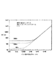
図3は、リターン電極の実効表面積と、電極で発生する実効無線周波数電流密度との間の関係をグラフに示す図である。しかし、このようなグラフを考慮する前に、このグラフは、本発明の原理を示すように簡略化してあり、実際のデータを表すものではないことに留意されたい。実際のデータは、かなり変動する可能性がある。図3には、RF電流密度を電極実効表面積に対してプロットしたものを示す。電極実効表面積は(今や当業者には明らかであるように)、患者の身体と実質上電気的接触を行う、リターン電極の表面の部分である。前述の説明から予想されるように、実効領域が広いとき、外科医の器具での電流は大きく(グラフの破線30)、対応するリターン電極間の電流密度は非常に低い(グラフの実線31)。これはもちろん、手術を実施するのに望ましい状態である。しかし、回路全体にわたって一定の電流が流れるものと仮定すると、実効表面積が減少するにつれて、リターン電極の両端間の電流密度(グラフの実線31)は増加し、それに対応して外科医の器具での電流(グラフの破線30)は減少する。実効表面積がある所定のところまで減少したとき、手術器具での電流は、手術を効果的に実施するには不十分なままとなる。
【0034】
電流密度の変化と、外科医の利用可能な電流の変化とは、実効表面積の変化と同時に生じることもあり、生じないこともあることを当業者は理解されたい。本発明の様々な実施形態は、電流密度と利用可能な電流がほぼ同時に変化するが、本発明の他の実施形態は、両者の間に遅れ期間を含むことがある。
【0035】
材料および電極の寸法に関して選択されるパラメータは、電流密度と、対応するリターン電極に隣接する組織温度の上昇とが、本明細書の冒頭で述べた制限を超過しないように選ばれる。このようなパラメータを適切に選択することによって、リターン電極を自己規制型とし、それによって上記で参照した追加の監視回路が不要となる。
【0036】
本発明の原理の説明を容易にするために、これまでは、主要な成分が抵抗性リアクタントおよび容量性リアクタントであるインピーダンスによって説明した。しかし、本発明の原理は、インピーダンスが抵抗性インピーダンス、容量性インピーダンス、および/または誘導性インピーダンスの任意の組合せを含む他の実施形態にも適用可能である。
【0037】
次に、実効誘電体層が電極の上面の物理誘電体層、患者が着用する手術衣の材料、ベッドシーツ、患者とリターン電極との間に置かれる他の手術室リネン、リターン電極を覆うように取り付けられた保護スリーブの材料、あるいはそれらの任意の組合せによって表される応用例に関連して、本明細書の発明をさらに説明する。
【0038】
図4は、本発明による電気外科リターン電極41が上面に配置された手術台40の斜視図である。手術台40の縁部は符号42で識別される。この手術台は、図示するようなホイールまたはローラを装着することができる従来型の脚部44a−44dを有するものとして示されている。テーブル40は、治療中に患者を支持する支持手段の機能を果たすことができる一構造である。しかし、他の様々な支持手段の構成も可能であり、必要な機能を果たすことができることを当業者は理解されたい。例えば、支持手段には限定はしないが、椅子、平板、ベッド、カートなどを含めることができる。
【0039】
図4では、テーブルの上面全体がリターン電極41で覆われているものとして示されているが、決して本発明の原理を実施するために全体を覆う必要があるわけではないことを理解されたい。したがって、従来型の電気手術発電器と共に使用するとき、リターン電極が与える必要があるのは、一般に使用するRF周波数で、十分な抵抗結合、容量結合、または誘導結合を提供するのに十分な実効作用表面積だけであり、それによって外科医の手術の実施が妨害されず、同時に望ましくない組織傷害が回避される。このことにより、従来の電気外科周波数では、必要なのは手術台上に載る成人の患者に関する胴、または図5に示すような椅子に座る患者の臀部の約半分の射影線以下であるということがわかった。しかし、実効作用表面積は、使用する材料、幾何学的構成、ならびに手術室のリネンの様々な層が電極を覆って配置される実例に応じて変動する。本明細書の原理をうまく利用して、そのような環境でリターン電極の実効作用表面積を定型的実験によって決定することができる。ある条件の下では、実効作用表面はわずか約7平方インチ(すなわち約45平方センチメートル)である。
【0040】
さらに、図6〜図8及び図10に示すリターン電極は長方形として示されているが、楕円形、あるいは例えば胴または患者の身体の他の主要部分のシルエットに従う輪郭にすることもできることは明らかであろう。このことから、電極を使用するときに、(1)患者の体表上のリターン電流密度が十分小さく、(2)電極と患者との間の電気インピーダンスが十分に小さく、それによって電気リターンパス中のどこかの位置で患者の皮膚が摂氏6度(6°)を超えて加熱されないように電気的エネルギーが集中せず、かつ(3)材料および幾何形状の特性が、選択した閾値レベル未満に電極の実効領域が減少した場合、外科医の器具で放散されるエネルギーが器具の電気手術モードで外科医が器具を効果的に引き続き使用するには不十分となるようなものとなるように、電極を構成することが重要である。
【0041】
当業者は理解するであろうが、電極が一般に上記の説明に従って動作するのに、患者の皮膚と本明細書のリターン電極との間に直接のオーム接触が存在する必要はない。手術衣などによって容量性リアクタンス(患者の身体と電極との間の間隔によって表される)が導入されるが、このような容量性リアクタンスにより、z3で識別されるインピーダンスが消滅するのではなく、変更されるからである。
【0042】
当業者には周知であるように、(例えば、電気外科で使用されるような)交流回路では、インピーダンスの容量性リアクタンスは、キャパシタンスと、リアクタンスに与えられる交流電気信号の周波数の両方の関数である。したがって、(オーム単位の)容量性リアクタンスは次式で示され、
【0043】
【数2】
![]()
上式で、Xcはオーム単位のリアクタンスであり、(π)は3.14159であり、fはヘルツ単位の周波数であり、Cはファラッド単位のキャパシタンスである。
【0045】
平行板コンデンサ中のキャパシタンスについては次式で示され、
【0046】
【数3】
![]()
上式で、Cはファラッド単位のキャパシタンスであり、κはコンデンサの実効平行板間にある材料の比誘電率であり、Aは、コンデンサの実効平行板のうち最も小さいものの平方メートル単位の領域であり、tは、実効平行板間の表面の、メートル単位の距離であり、ε0は、ファラッド/メートル単位の空気の誘電率である。したがって、電極回路キャパシタンスがかなりのものとなる実施形態で最大許容温度上昇基準を満たすためには、発電器源の周波数、患者の身体と電極との間隔、および電極の実効導電領域と隣接する身体表面との間にある材料に応じて、様々な電極の最小サイズが必要となる可能性がある。したがって、本発明の原理は、電気外科エネルギーの広範な周波数に対して適用可能であるが、リターン電極の最小サイズに関して本明細書で述べるように、従来の電気外科エネルギー発生器で一般的に利用される周波数が用いられる。
【0048】
電極の実効サイズを約3平方インチ(約19平方センチメートル)まで縮小する、現在使用されている使い捨てリターン電極が、外科医が手術を実施することを妨げるレベルまでRF電流を減少させず、かつ患者が外傷を負うレベルまでRF電流を集中させないことは当業者に周知である。しかし、患者の身体と電極との間にある程度の間隔を与えるには、本明細書の発明によるリターン電極は、手術衣によって実現されるような比較的小さい患者の皮膚との分離を用いる場合、または介在する手術衣を全く用いない場合、約7から約11平方インチ(約45cm2から70cm2)の間の最小実効領域を必要とする。患者が患者の胴上部のサイズ以上の電極上に置かれる場合、このような実効領域を得ることは容易である。
【0049】
この実施形態に対して望まれる誘電体の特性は、選択されるゴム、プラスチック、およびリターン電極用の材料として十分に使用することができる他の関係する材料の特性に十分に匹敵する。前述のように、このようなリターン電極では、インピーダンスを必要な限り小さくするために十分なだけのリターン電極が患者に接近して配置されない場合、電気手術発電器からの電流は、外科医が手術を実施することが難しくなるレベルまで減少することになる。したがって、この実施形態では、手術衣によって表されるある追加のキャパシタンスが挿入されても、前述の特徴は引き続き生じることになる。
【0050】
前述のように、図5は、本発明による電気外科リターン電極51が座部の上面に配置された手術椅子50の正面図である。したがって、患者が座部に座っているとき、臀部および大腿の上部が載り、リターン電極と十分に接近し、その結果それらの間の結合により、前述の基準を満たすインピーダンスが与えられる。すなわち、リターン電極と患者との間の電気インピーダンスが十分に小さく、外科医が処置を実施することが可能となり、同時に、電流密度が十分低く、電気的リターンパス中の任意の位置で患者の皮膚を摂氏6度(6°)よりも高い温度に加熱するには不十分な電気的エネルギーがリターンインピーダンスの両端間に発生することが実現される。
【0051】
図6は、本発明による他の電気外科リターン電極の上面図である。電極の上部に露出する表面、すなわち作用表面はやはり、低インピーダンスに関する前述の基準を満たすように大きい。電極が手術台の表面全体、あるいは歯科用椅子または他の患者用椅子の座部表面全体を覆うことは必要ではないが、ある場合には患者の臀部または胴の射影領域の表面積よりも広い表面積を設け、それによって患者が処置中に位置を移動した場合に、患者の十分な部分が電極表面と依然として重なり、その結果実効インピーダンスが依然として前述のレベル未満となるようにすることが有利であることがわかった。
【0052】
この時点で、本発明の特徴を理解することに特に関係すると考えられる、本明細書の発明による改良型の電極の特性を強調することが助けになるかもしれない。まず、前述のように、直接的に、または介在する導電性または非導電性ゲルによって電極が患者と直接接触する必要がない。加えて、この電極のサイズは大きいので、電極を患者の身体の輪郭に適合するように調整する必要がない。これに関連して、選択される材料および幾何形状を用いて、本明細書の自己補正型および自己規制型の原理を、わずか約7平方インチ(すなわち約45平方センチメートル)の作用表面積の電極で達成することができるが、電極の露出上面の作用表面積の好ましい範囲は、約11から1500平方インチ(すなわち約70から9680平方センチメートル)である。以前に行った提案よりも作用表面積で電極を何倍か大きく(一般には少なくともより大きい桁に)作成することによって、患者の皮膚に直接的に装着するか、またはゲルを用いて身体に装着することによって直接的に身体に装着する必要がなくなる。
【0053】
図6に示す本明細書の発明による電極は、電極で使用するときに作用表面の各平方センチメートルごとに与えられる実効dc抵抗が約8000Ωよりも大きくなる導電性プラスチック、ゴム、または他の柔軟な材料で作成することができる。シリコーンまたはブチルゴムは柔軟で、容易に洗浄可能かつ消毒可能であるので、特に魅力的な材料であることがわかった。あるいは、必要な導電率を与えるように変質した、本質的に比較的高抵抗で柔軟な材料でリターン電極の本体を作成することもできる。この材料の好ましい例は、炭素繊維などの導電性繊維が浸透したシリコーンゴム材料、あるいはカーボンブラックなどの他の導電性物質が多数分散し、金、銀、ニッケル、銅、鋼、鉄、ステンレス鋼、黄銅、アルミニウム、または他の導体が多数分散したシリコーンゴム材料である。
【0054】
図6をさらに参照すると、電極41に取り付けられ、従来型の電気的リターンを電気外科無線周波数エネルギー源(図示せず)に供給する従来型の電気コネクタ54が存在することがわかる。コネクタ54は、シートに電気的接続を行う接続手段の機能を果たすことができる別の構造である。コネクタ54は、所望の機能を果たすために可能な構造の一例に過ぎない。他の様々な構造も、必要な機能を果たすことができることを当業者は理解されたい。
【0055】
図7は、図6の線7−7に沿った断面である。図7は、電極46を示し、これは、電流が外側に端子54まで伝導することを促進するための薄型高導電性下部層46cを含むことを除き、図2A〜図2Cの電極20と同様である。1つの好ましい形態では、電極の厚さは、約1/32インチから1/4インチ(約0.08mmから0.64mm)の範囲にある。この範囲と、上述した材料本体のインピーダンスの範囲、および上部誘電体層の容量性リアクタンスの範囲により、必要なインピーダンスとともに、使用および扱いが容易となる所望の物理的柔軟性が得られる。
【0056】
図8は、図7の断面と類似の断面であるが、本明細書の発明による患者の手術衣によって与えられる分離を示す複数層の実施形態を示す。図8では、層46a(図7の層46と同様)と、その上に載る、絶縁誘電体層、患者の手術衣、手術室のリネン、保護スリーブまたはシース、あるいはそれらの任意の組合せを表す実質上容量性の層47が示されている。図6及び図7の電極と類似の構造に加えて、図8の導電層47aは、金、黄銅、アルミニウム、銅、銀、ニッケル、鋼、ステンレス鋼、導電性カーボン、導電性流体、ゲル、食塩水などのシートまたはスクリーンを含むことができる。さらに図8を参照すると、層46aの底面を覆う別の誘電体層47bがあるのがわかる。
【0057】
図9は、図6〜図8の実施形態のいずれか1つを囲むように適合されたスリーブ50の斜視図である。したがって、不浸透性材料のスリーブを使用して電極を汚染から保護することによって電極自体を洗浄する必要をなくすることが望ましい状況で、保護エンベロープ内に前述のリターン電極形の電極を囲むことが任意選択で実現される。使用後に、電極をスリーブから単に引き抜き、スリーブを廃棄することができる。当業者には明らかであろうが、このようなスリーブはビニルプラスチック、ポリエステル、またはポリエチレンなどの様々な周知の材料のいずれからも作成することができることが好ましい。
【0058】
図10は、図9に示したスリーブ内に囲まれた、図6〜図8に示した実施形態のうちの1つを示す図である。図10からわかるように、スリーブ50の外面50aがあり、図6に示した電極41がスリーブ50内に囲まれることが例示的に示されている。
【0059】
(合計電極設置パッドインピーダンスおよび自己規制機能)
図11は、導電性金属裏当て61および半絶縁性層62からなる電気外科電極60を示す図である。電極60、より具体的には半絶縁性層62は、その上の患者を表す別の導電層63と接触する。電気外科リターン電極60の自己規制機能(電流密度を閾値レベル未満に維持する)は、電極60のインピーダンスが半絶縁性層62だけから生じるか、それとも導電性金属裏当て61および/または導電層63の組合せで生じるかに関わらず、電極60の合計インピーダンスによって生じる。さらに、合計インピーダンスは、導電性金属裏当て61、半絶縁性層62、および/または導電層63の様々な抵抗性、誘導性、および/または容量性成分から生じる可能性がある。
【0060】
電極60は、バルク固有抵抗ρおよび厚さtを有する半絶縁性材料62の単一層を含んでいる。導電面と患者との間に配置された領域Aは、コンデンサ(C)と並列の抵抗器(R)としてモデル化することができる。
【0061】
説明を簡単にするために、電極60がコンデンサに並列に接続された抵抗器としてモデル化される純粋に抵抗性の状況で自己規制するための、電極60の抵抗の要件を決定する。純粋に抵抗性のケースで自己規制するための最小要件の計算に続いて、任意のインピーダンスに対して、抵抗性、容量性、および/または誘導性成分のいずれかに関わらずこの分析を一般化する。
【0062】
したがって、コンデンサの組合せと並列の抵抗器と同等な合成された合計インピーダンスの大きさは次式で示され、
【0063】
【数4】
上式で、jはリアクタンスの虚数成分であり、ωは角周波数でω=2πfと定義される。ただしfは電気手術発電器の周波数である。インピーダンスの大きさは、次式で示される。
【0065】
【数5】
領域A、厚さt、バルク固有抵抗ρ、および材料の比誘電率κに対する、RおよびCの依存性は、
【0067】
【数6】
![]()
および
【0069】
【数7】
![]()
によって定義される。上式では誘電率ε0=8.85×10⁻¹²F/mである。これによってRおよびCを置き換えると、合計インピーダンスの大きさは、
【0071】
【数8】
によって与えられる。AAMI規格によれば、電気外科電極の合計インピーダンスは、通常の動作条件の下で75Ω未満であるべきである。したがって、
【0073】
【数9】
であることが好ましい。βを、
【0075】
【数10】
![]()
と定義する。β<<1である場合、電極は、AAMI規格に比べて非常に小さいインピーダンスを有することになり、外科医が、電極による電気外科切断能力の劣化に気付くことがなくなる。β>>1である場合、電気外科電極は、外科医が電気外科手術を実施することができなくなるほど大きなインピーダンスを有することになる。βを上記の不等式で用いると、式は等式になる。
【0077】
【数11】
患者と接触する広い電極領域を電極が有するとき(図15)に自己規制が行われることが好ましい。しかし、患者が全電極領域のうちの小部分だけに接触するとき(図11)にも自己規制を行うことが必要である。自己規制を適切に動作させるためには、電気外科リターン電極の接触領域Aを通る全電流をIとして、電流密度(I/A)が基準値
【0079】
【数12】
を超えないことが必要である。AAMI規格は、通常の電気外科電流が500−700mA程度であることを示している。平均を超える出力を用いる外科手術に対して予想される電流に関して1000mA=Imaxを安全な上限として設定した場合、Icriticalを超えることなく電極に電流を戻すためには、伝統的な電気外科リターン電極に関する接触領域Acontact(min)が有さなければならない最小サイズは次式で示される。
【0081】
【数13】
電極が患者と接触する時間、患者の皮膚(すなわち固有抵抗など)の電気的特性、患者が導通する熱量、患者の初期皮膚温度などの変化のために、Imaxが患者によって変動する可能性があることを理解されたい。従来技術に従って設計された電気外科リターン電極では、Imaxが維持されるとともに、患者との接触領域がAcontact(min)未満に減少した場合、(I/A)critial>100mA/cm2となるので熱傷が生じる可能性がある。100mA/cm2は熱傷の閾値である。一方、本発明は、接触領域がAcontact(min)に減少することによって引き起こされる熱傷の可能性を制限するとともに、接触領域が著しく減少したときの電気外科処置も防止する。したがって、電極60の適切なインピーダンスを選択することによって、A<Acontact(min)のとき、電流Iは常にImax未満となる。
【0083】
したがって、領域Acontact(min)を有する小さい電極と、より大きい金属はくとの間のインピーダンスは単に、
【0084】
【数14】
とはならない。電流は、患者の接触領域Acontact(min)の直下にはない領域を通じて流れることできるからである(図12)。絶縁層の全領域がAcontact(min)である場合に予想される電流よりも約10〜20%大きい電流が患者の接触領域Acontactを通じて流れる。換言すれば、電極の実効インピーダンスは、追加の電流を引き起こすこの縁効果が存在しない場合に通常予想される電極の実効インピーダンスよりも10〜20%小さい。
【0086】
前述のように図12は、上側の患者との接触領域が全電極表面積よりもずっと小さいとき、電極の半絶縁性部分を通る電流分布を示す図である。電流は接触領域の周囲の平行な経路を流れ、したがって、電流に対する全インピーダンスが減少し、それによって実効領域が約10〜20パーセント増加する。この図12で、不透明な領域、すなわち濃く陰影を付けた領域は電流密度が高いことを示し、より明るい領域、すなわち薄く陰影を付けた領域は電流密度が低いことを示す。
【0087】
電極を自己規制型にし、かつAAMI規格によって定義されるのと同様に有効なものとするために、Acontact(min)が約7cm2から約22cm2までの値を有することが好ましく、100mAから約2000mAの間の電気外科電流に対しては、約10cm2であることがより好ましい。同様に、βは約10から約50までの範囲にあることが好ましく、約10の値を有することがより好ましい。Acontact(min)およびβに対して様々な値を使用して、前述の縁効果を補償するための因子1.2を挿入しながら、様々な電気手術発電器周波数ωで、式(11)を厚さtについてバルク固有抵抗ρの関数として解くことが好ましい。本明細書で説明する特定の具体的な実施形態では、因子1.2は、式の固有抵抗の項とリアクタンスの項の中に含まれている。しかし、因子1.2は、抵抗の項とリアクタンスの項の両方に対して幾何形状依存であり、変動する可能性があることを当業者は理解されたい。加えて、値1.2は、現在説明している自己規制型電極の例示的幾何形状に基づいており、電極の幾何形状が変動するとともに、様々な縁効果を補償するために変動する可能性がある。
【0088】
得られる式(自己規制に影響を及ぼすパラメータの相互関係を識別し、定義する式)は次式で示される。
【0089】
【数15】
式(15)を使用して、図13に、κ=5として、電極の厚さに伴う最小バルク固有抵抗の変化を示す。考えられる最大電極厚は、約0.5から約4インチ(約1.3cmから約10.2cm)の範囲となり、より好ましくは厚さ約1インチ(約2.5cm)である。この厚さを超えると電極は扱いにくくなり、患者にとって使い心地が悪くなることがある。したがって、自己規制型にするには、このような厚さの電極に対する最小バルク固有抵抗を約4000Ω・cmとする。
【0091】
式(15)およびその説明は、電極60(図11)を自己規制型にするのに必要なバルク固有抵抗の代表例である。しかし、これまでの分析を繰り返して、主に容量性または誘導性の成分、あるいは抵抗性、容量性、および/または誘導性の成分の組合せを使用してモデル化される電極に対して、必要な自己規制型インピーダンスを得ることができることを理解されたい。したがって以下では、このようなインピーダンスがインピーダンスの抵抗性、容量性、および/または誘導性成分から生じるかに関わらず、電極60のバルクインピーダンスに対する自己規制要件について説明する。
【0092】
本発明の電気外科電極の自己規制挙動は、十分なリターンインピーダンスが存在することにより得られ、患者と電気外科リターン電極との間の接触領域が実質上減少するとき、電極部位での熱傷が不可能となる。上述したように、最大電気外科電流1000mAと、電流密度を100mA/cm2未満に保つという要件とを組み合わせることにより、最小の安全接触領域10cm2が得られる。
【0093】
一般にこの要件は、コンデンサ、抵抗器、さらにはインダクタの直列または並列の組合せを含む様々な構成でつながれた任意の数の電子構成要素に適合させることができる。ただし、接触領域が10cm2に減少するときに、得られる回路によって与えられる合計インピーダンスが約75β以上であることを条件とする。
【0094】
電気手術発電器のリターン電極と患者との間の回路の合計インピーダンスをZTOTと定義する。このインピーダンスは、患者とリターン電極の間に挿入された材料の容量性、抵抗性、および誘導性特性によって生成される。材料のインピーダンスの体積に独立な指標である、材料の「バルクインピーダンス」ηを以下のように定義する。このηは周波数に依存する。
【0095】
【数16】
![]()
上式でAは材料の領域であり、tは厚さである。これは、初めに述べた、体積依存オーム抵抗Rと、関係する「バルク固有抵抗」ρと呼ばれる、抵抗性材料の体積に独立な特性との間の関係と同様である。
【0097】
自己規制要件を記述する1つの方法は、ηによって表される。
【0098】
【数17】
![]()
したがって、
【0100】
【数18】
![]()
(最小バルク固有抵抗の指定する)先のケースについて、A=Acontact(min)=10cm2(約1.55インチ2)、β=10、およびt=tmax=1インチ(約2.5cm)を使用し、縁効果(edge effect)を補償するために因子1.2を使用して、純粋な抵抗性電気外科電極に対するηを求める。
【0102】
【数19】
![]()
したがって、純粋に抵抗性の場合、バルクインピーダンス(η)は、電極の導電性材料のバルク固有抵抗(ρ)として識別される。しかし、式(19)の結果は、すべての材料と、抵抗性、容量性、および誘導性成分、ならびにそれらの組合せを含む電気的成分とに対して一般化される。電気外科電極のバルクインピーダンスが4000Ω・cmよりも大きい限り、自己規制挙動が抵抗性インピーダンス、容量性インピーダンス、誘導性インピーダンス、またはこれらのインピーダンスの何らかの組合せであるかに関わらず、電極は自己規制型となる。
【0104】
代替例として、絶縁(誘電体)材料で被覆された導電性/抵抗性リターンプレートを使用して自己規制型電気外科電極を構築することができ、または誘電体材料から患者の手術衣を構成し、金属製または抵抗性リターン電極を使用することができる。これらの装置の全体の効果により、容量性インピーダンスと直列の抵抗性インピーダンスが生み出される。
【0105】
抵抗性および容量性インピーダンスによってリターン電極をモデル化する、上述で定義した例の場合、電気外科電極の合計インピーダンスは、抵抗性インピーダンスと容量性インピーダンスの和である。
【0106】
【数20】
![]()
材料バルク固有抵抗、比誘電率、領域、および厚さによって表すと、合計インピーダンスは、次式で示される。
【0108】
【数21】
![]()
上式の両辺に領域Aを掛け、厚さtで割ることによって、バルクインピーダンスηを導出することができる。
【0110】
【数22】
![]()
バルクインピーダンスの大きさは、次式で示される。
【0112】
【数23】
【数24】
![]()
を要求した場合、
【0115】
【数25】
となる。
【0117】
したがって、縁効果は、電極のバルクインピーダンスを約10〜20パーセント減少させ、それに対応して、自己規制型電極の実効領域が約10〜20パーセント増加し、望ましくない電気外科的熱傷の可能性が低減する。
【0118】
図14は、様々な電気外科周波数に関して、バルクインピーダンスηに対してA/tをプロットした図である。y軸は、バルクインピーダンスの関数として、自己規制型挙動を有するためのA/tの最小比を有する。バルクインピーダンスは常に4000Ω・mよりも大きくなることが必要であることに留意されたい。プロットの右側では、曲線のすべてが1つに収束する。この状況では、回路の合計インピーダンスは抵抗性成分が優勢であり、したがって周波数に無関係である。左側では、回路インピーダンスは、電流の容量性伝導が優勢である。この領域において低オーム抵抗で十分な合計インピーダンスを提供するためには、数百から約10000の領域対厚さ比が必要である。
【0119】
したがって、得られる可能な最低のバルクインピーダンスは、Twentierの米国特許第4088133号明細書によって予想されるバルクインピーダンスよりも大きい。したがって本明細書の発明による自己規制型電極は、周知の従来技術によって開示も提案もされていないことがわかる。本明細書の発明による製品は、電極領域または電極の厚さとは無関係に、絶縁材料のバルク固有抵抗などのバルクインピーダンスの単純なテストによって、従来の技術と容易に識別することができる。
【0120】
(材料の幾何形状と電源の相互関係)
図11〜図17は、上述した自己規制型動作を得るために使用する材料の幾何形状および特性を定義するための図である。以下では、容量性伝導を利用する電気外科処置に使用することができるとともに、依然として自己規制型の電極に関係する例示的情報および例を提示するための説明を行う。本明細書では、容量性伝導の下で機能する電気外科電極に関して説明を行うが、当業者には周知の通り、抵抗性伝導および誘導性伝導に対して同様な例示的情報および例を提供することができる。
【0121】
図15に、導電性金属裏当て61と、バルク固有抵抗ρ、厚さt、および領域Aを有する材料の半絶縁性層62とからなる電気外科電極60を示す図である。この電極は、電極の上の患者を表す別の導電層63と接触している。この回路は、コンデンサCと並列な抵抗器Rとしてモデル化することができる(図16)。抵抗Rは、以下の式によりバルク固有抵抗ρ、領域A、および厚さtと関係付けられる。
【0122】
【数26】
![]()
キャパシタンスCはほぼ、領域A、厚さt、誘電率ε0=8.85×10⁻¹²F/m、および材料の比誘電率κと関係付けられる。
【0124】
【数27】
![]()
コンデンサのインピーダンスの大きさは、
【0126】
【数28】
![]()
となる。
【0128】
容量性経路による電流と、抵抗性経路による電流との比Yは、
【0129】
【数29】
となる。
【0131】
この比Yは、電極領域および厚さには無関係であり、κおよびρだけに依存する。主に容量性結合の場合Y>>1であり、一方、主に抵抗性電流の場合Y<<1であり、容量性電流と抵抗性電流との間の境界はY=1である。
【0132】
【数30】
![]()
これをε0の値と共に使用して、所与の定格値κおよびω=2πfについて、容量性伝導に関して、必要な値ρを求めることができる。ただしfは電気外科発電器の周波数である。
【0134】
【数31】
![]()
ほとんどの絶縁材料に対して、κは3から5の範囲にある。市販の電気手術発電器は現在、200kHzから4MHzの範囲の動作周波数を有する。κ=5かつf=4MHzの場合、電気外科電極がその電流のほとんどを容量性結合を介して戻すために、ρ≧1×10⁵Ω・cmであることが好ましい。κ=3かつf=200kHzである場合、ρ≧3×10Ω・cmであることが必要である。
【0136】
容量性結合を介して導出された合計電流の割合は、以下によって与えられる。
【0137】
【数32】
図17は、様々な周波数電気手術発電器についての容量性結合の割合(%)を示す図である。極限(4MHz)では、電流の大部分が容量性結合を介して通過するためには最小バルクインピーダンス105Ω・cmが必要となる。
【0139】
(減圧機能を有する電極)
次に図18〜図23を参照すると、本発明の様々な他の代替実施形態が示されている。図18〜図23に示されている電気外科電極は、電気外科処置中に患者の熱傷を防止する目的で自己規制型であり、長期の外科的処置中に発症することのある褥瘡性潰瘍または褥瘡の発症の可能性を低減する助けになるパッドを含むことができる。自己規制型特性と褥瘡低減特性とを組み合わせることによって、本発明の電気外科電極は、すべてのタイプの外科的処置中に、患者が褥瘡を発症することから保護するとともに、本明細書で述べるような自己規制型電気外科電極の利点を提供する。任意選択で、本発明の電気外科電極は、電気外科電極が外科的処置中に患者を加熱および/または冷却することが可能となる、加熱および/または冷却する機能または特性を含むことができる。任意選択で、このような加熱および/または冷却特性は、長期の外科的処置中に褥瘡性潰瘍または褥瘡の発症を制限する電気外科電極および/またはパッドと組み合わせることができる。
【0140】
具体的には図18及び図19を参照すると、電気外科電極80が示されている。一実施形態では、電気外科電極80は、導電要素すなわち電極82と、パッド84とを含む。一構成では、電極82は、導電要素として使用するときに電気外科電極80の作用表面(患者と接触または近接する表面)の各平方センチメートルごとに与えられる実効DC抵抗が約8000オームよりも大きくなるか、または4000Ω・cmよりも大きいバルクインピーダンスを与える導電性プラスチック、ゴム、または他の柔軟な材料で作成される。必要なインピーダンスを与えるのに様々な材料が適している。例えば、シリコーンまたはブチルゴムは柔軟で、容易に洗浄可能、殺菌可能、かつ消毒可能であるので、特に魅力的な電極82用の材料であることがわかった。あるいは、別の実施形態では、必要な導電率を与えるように変質した、本質的に比較的高抵抗で柔軟な材料で電極82を作成することもできる。この材料の例は、カーボンブラックなどの導電性繊維、多数の金、銀、ニッケル、銅、鋼、鉄、ステンレス鋼、黄銅、アルミニウム、または他の導体が浸透したシリコーンゴム材料である。
【0141】
さらに別の代替構成では、電極82は、限定はしないがマイクロ波放射、赤外線(IR)放射、紫外線放射(UV)放射、X線放射、無線周波数(RF)などの1つまたは複数の電磁放射波長に対してほぼ透過性の材料から製造することができる。これにより、特定の波長の電磁放射を使用してある医療処置を実施する間、電気外科電極80の他の構成要素が1つまたは複数の電磁放射波長に対して透過的であるとき、電極82および電気外科電極80を定位置に維持することが可能となる。
【0142】
電極82が電極の機能を果たすことができる限り、すなわち電極82を通じて電流を流すことができる限り、電極82は他の様々な構成を有することができることを当業者は理解されたい。例えば、別の実施形態では、電極82は、電気外科電極80を電気外科無線周波数エネルギー源(図示せず)に接続することを容易にする薄い高導電性下部層を含む。他の実施形態では、電極82は、複数の層の導体から構成される。さらに他の実施形態では、電極82は、先に述べた電気外科電極と同様の、内部導電層を実質上囲む外部誘電体層を含む。
【0143】
再び図18を参照すると、電極82がパッド84に取り付けられている。図19に示すように、パッド84は、内部室92を形成する上面86および下面88を有する。上面86は、患者の体表に向かうように構成され(それによって電気外科電極80の作用表面として働く)、下面88は電極82に接続される。このようにして、パッド84は、パッド84上に位置する患者の重量および下方向の力をパッド全体にわたって支持および分散し、褥瘡が発症する可能性を低減する。他の方法として、下面88が患者の上に載るように適合することもでき、あるいは下面88が手術台、椅子など患者が載る構造上に載るように適合することもできる。同様に、上面86が電極82と接続するように構成することもできる。
【0144】
パッド84の内部室92には材料94が充填される。材料94により、減圧特性を有するパッド84が実現する。より具体的には、材料94で規定された体積が内部室92内に保持されるので、個人がパッド84上に載るとき、材料94は患者の下方の力を材料94全体にわたって分散し、それによって骨の隆起が位置するところの患者組織の部分に加えられるポイントフォース(point force)が減少する。このようにして、パッド84は患者に加えられる圧力を低減し、それによって褥瘡の発症を制限する。任意選択で、減圧特性を実現する材料94だけを用いる代わりに、材料94、パッド84を形成する材料、および/または電極82を形成する材料の組合せによって、本発明の減圧特性を実現することもできる。
【0145】
本発明の他の実施態様によれば、材料94は、パッド84を通じて流れる電流を低減する誘電体層として働くことができる。あるいは、材料94は、材料94を通って電流が伝達する助けとなるように、導電性材料の形態を取ることもできる。加えて、材料94は、電気外科処置中に熱の拡散のためのある熱質量を提供することができる。上述したように、AAMIは、電気外科処置中、患者の組織の温度上昇が摂氏6度(6℃)未満のままであるべきであることを要求している。材料94によって供給される熱質量は、患者の身体全体にわたって熱を拡散する助けになり、かつ電気外科電極80の自己規制型特性とあいまって、患者が熱傷を負う可能性のある熱点の可能性を実質上なくする。したがって、材料94用に使用される物質は、電気外科処置中に複数の機能を果たすことができる。
【0146】
一般には、材料94は、電気外科電極80に対して必要な減圧特性、誘電体特性、および/または導電特性に応じて、1つまたは複数の固体、液体、気体、またはそれらの組合せの形態を取ることができる。例えば、この実施形態では、材料94は、ソルベタン(sorbethane)などの低デュロメータレベルを有する弾性ゲルである。限定はしないが、ソルベタンに加えて、ウレタン、シリコーン、親水性エラストマーまたはヒドロゲル、ビニル、またはビニルアルコールの高分子化学、または他の類似の材料および技術に基づくような、様々な他の弾性ゲルを使用することができる。加えて、材料94は、水、食塩水、水ベースの材料、導電性油などの形態を取ることができる。
【0147】
所望の機能を果たすことができるパッド84の様々な他の構成が存在することを当業者は理解されたい。例えば他の実施形態では、パッド84には材料94がなく、固体であるが柔軟なフォームタイプ材料から形成される。したがって、パッド84は全体として、減圧特性を実現することができる。
【0148】
パッド84は、洗浄、消毒、殺菌などを行うことができる様々な材料から製造することができる。したがってパッド84は、限定はしないが、ビニルプラスチック、ポリエステル、ポリエチレン、ポリウレタン、柔軟性のあるシートポリマーなど様々なタイプの材料から製造することができる。一般に、パッド84は約0.5から約4インチ(約1.3から約10cm)の厚さを有する。好ましくは、パッド84は約0.5から約3インチ(約1.3から約7.6cm)の厚さを有する。さらに好ましくは、パッド84は約1から約2インチ(約2.5から約5.1cm)の厚さを有する。
【0149】
電気外科電極80、電極82、パッド84、および材料94を形成する材料により、電極82から患者への電流の通過が制御される。したがって一実施形態では、パッド84および材料94は絶縁体であり、他の構成では、パッド84および/または材料94は導電性であり、患者を流れる電流が通過する助けとなることができる。電気外科電極80の合計インピーダンスが本明細書で定義される制限内にある限り、すなわち作用表面の各平方センチメートルが8000オームよりも大きいか、またはバルクインピーダンスが4000Ω・cmよりも大きい限り、電気外科電極80の様々な要素、すなわち電極82、パッド84、および材料94は、1つまたは複数の抵抗性、誘導性、および/または容量性インダクタンス成分をバルクインピーダンスに与えることができる。このようにして、電気外科電極80は自己規制型となり、同時に減圧特性も実現する。
【0150】
電気外科電極80の様々な他の構成も適切であることを当業者は理解されたい。例えば、他の構成では、手術台内、あるいは手術台クッション内に電気外科電極80を構築し、それによって手術台が電気外科処置中に褥瘡低減機能および自己規制型機能を有することができる。他の構成では、電気外科処置に対して電気外科電極80を使用する必要はなく、単に絶縁パッドまたは褥瘡パッドとして使用することができる。このようにすることで、本明細書で説明した電気外科電極80および他の関係する電極を作成することによって、医療機関が複数の異なる褥瘡パッドおよび電気外科リターン電極を購入し、備えておく必要が軽減される。加えて、この電気外科電極は消毒可能、浄化可能、洗浄可能、かつ殺菌可能であるので、複数回使用することができる。前述のように他の褥瘡装置はいくつかの欠点を有するものの、本発明の他の構成では、他の褥瘡装置と共に電気外科電極80を使用することができる。
【0151】
一般に、電気外科電極80の構成により、臨床家が電気外科電極80上、またはその下に患者を配置することが可能となる。電気外科電極80の重量により、外科的処置中に電気外科電極80が定位置に維持される。他の褥瘡装置は様々な欠点を有するが、電気外科電極80を患者の上に配置するとき、臨床家は、電気外科電極80を他の褥瘡装置と組み合わせることができる。褥瘡パッドと電気外科電極の組合せを作成することにより、バルクインピーダンスを定義することができ、それによって、バルクインピーダンスが未知の他の褥瘡装置と、このような電気外科電極とを組み合わせるときに、電気外科電極の効率が低下する可能性がなくなる。
【0152】
次に図20を参照すると、電気外科電極100の他の構成が示されている。本明細書で説明した他の電気外科リターン電極に関して先に論じた特徴のほとんどが、電気外科電極100にも当てはまる。電気外科電極100は、材料106で充填された内部室104を有するパッド102と、導電要素すなわち電極108とを有する。パッド102は一般に、患者がパッド102上に座るべきか、仰臥位になるべきか、あるいは他のある姿勢になるべきかに関わらず、患者と協働するように構成される。この実施形態では、パッド102は、限定はしないが、ポリウレタン、ポリエチレン、ビニル、または内部室104内に材料106を含むことになる類似の材料などの薄い誘電体供給材料から形成される。
【0153】
内部室104を充填する材料106により、外科的処置中に患者が電気外科電極100上に載るときに患者によって加えられる下方向の力に対向する上方向の力が与えられる。このようにして、電気外科電極100は、患者が褥瘡性潰瘍または褥瘡を発症する可能性を制限する減圧特性を有する。任意選択で、材料106、パッド102を形成する材料、および/または電極108を形成する材料の組合せによって、本発明の減圧特性を実現することもできる。
【0154】
この構成では、材料106は、様々な電気外科処置中に、患者と、活性電極と、電気外科装置(図示せず)との間で電流を移送する導体として働く。任意選択で、材料106は、材料94、および本明細書で説明した他の材料と同様の構成を有し、同様の機能を果たすことができる。
【0155】
電極108は、パッド102および材料106と連絡する。電極108、したがって電気外科電極100が電気外科無線周波数エネルギー源または電気外科装置(図示せず)と電気的に結合することを可能にする接触110を電極108は含む。この実施形態では、電極108がパッド102の内部室104内に配設される。電極108は、パッド102の内部室104の底面に対して配置することができ、内部室104内部の中心に配置、すなわち自由浮遊することができ、パッド102の内部室104の上面に対して配置することができ、内部室104の内部表面上に形成することができ、あるいはそれらの任意の組合せで配置することができる。この実施形態では、電極108は、内部室104のかなりの部分を横切る。しかし点線で示したように、電極108は内部室104に部分的に進入し、内部室104を充填する材料106と電気的に連絡することができる。したがって、電極108は、内部室104内にかなりの距離だけ延在することができ、内部室104内に部分的に延在することができ、内部室104の内部表面と連絡することができ、あるいはこれらの任意の組合せとすることができる。
【0156】
この具体的な実施形態では、電極108は、限定はしないが、銅被覆ポリエステルファブリック材料などの導電性材料の薄いシートとすることができる。あるいは、電極108は、電極108が電流を導通することができると共に所望の柔軟性を有する限り、他の様々な材料のうちの1つでよい。したがって、電極108は、導電性または含浸プラスチック、ゴム、または他の柔軟な材料、金属、複合材料、2つ以上の金属の混合などでよい。さらに他の実施形態では、電極108は、先に説明した電気外科リターン電極と類似の2つのポリマーシートの間に挟まれた導電性材料を含む。
【0157】
次に図21を参照すると、電気外科電極120の他の構成が示されている。本明細書で説明した他の電気外科リターン電極に関して先に論じた特徴のほとんどが、電気外科電極120にも当てはまる。したがって図示するように、電気外科電極120は、導電要素すなわち電極122と、バフルドパッド(baffled pad)124とを含む。
【0158】
この実施形態では、バフルドパッド124は、長期の外科的処置の間に発症する褥瘡性潰瘍または褥瘡の発症を低減する助けとなるように構成される。図示するように、バフルドパッド124は、一般に長方形のボディを有するが、本明細書に含まれる教示の点から当業者には周知であるように、バフルドパッド124は様々な他の構成および断面形状を有することもできる。
【0159】
この構成では、バフルドパッド124は、患者と接触するように構成された上面126と、手術台、カートなど、患者を載せるべき表面と接触するように構成された、上面126から離れた下面128とを有する。上面126と下面128との間には、材料132で充填された内部室130が配置される。一実施形態では、内部室130は、実質上バフルドパッド124の長さ(あるいは幅)方向に沿って延在する1つまたは複数のバフル136a〜136nによって連結される、いくつかの別々の小室134a〜134nに分割される。各バフル136a〜136nは、開口138a〜138nにより、隣接する小室134a〜134nが互いに連通することが可能となると共に、実質上バフルドパッド124の長さ(または幅)方向に沿って延在するように構成される。このようにして、患者がバフルドパッド124上に載るとき、材料132が小室134a〜134nの間を充填し、その間を移動することができる。
【0160】
この構成では、バフルドパッド124は、縫い合わせることができ、熱ボンドすることができ、あるいはスリーブタイプ構成を作成するように接合または処理することができる材料の1つまたは複数のシートから製造することができる。さらに、バフルドパッド124およびバフル136a〜136nは、限定はしないが、ビニルプラスチック、ポリエステル、ポリエチレン、ポリウレタン、または類似の材料など様々な材料から製造することができる。ボディおよびバフル136a〜136nを接合または接着することができ、あるいはバフルドパッド124を作成するように協働することができる限り、バフルドパッド124のボディは、バフル136a〜136nとは異なる材料から製造することができることを理解されたい。
【0161】
さらに、バフルドパッド124の構成は、当業者には周知のように、様々な他の構成を有することができる。例えば他の構成では、患者か、あるいは患者および電気外科電極120を載せるべき表面と接触するように上面126または下面128を構成することができる。さらに他の構成では、各小室134a〜134nは独立した室であり、他の小室134a〜134nと連通せず、それによって別々に材料132で充填することが必要となる。さらに他の構成では、小室134a〜134nのうち1つまたは複数が、バフルドパッド124の縦方向に沿って位置し、一方、小室134a〜134nのうち1つまたは複数が、バフルドパッド124の縦方向とほぼ垂直に位置し、かつバフルドパッド124の縦方向に沿って位置する1つまたは複数の小室134a〜134nと連通する。本発明の別の構成では、バフルドパッド124は、内部室130またはその個々の小室134a〜134nと連通する、バフルドパッド124のボディを貫く1つまたは複数の開口を含むことができる。したがって、ユーザは、内部室130にアクセスすることができ、その中に必要な量の材料132を入れることができる。一般に、各小室134a〜134nの向きおよび構成は、電気外科電極120のユーザの必要に応じて変化する。
【0162】
上述したように、各小室134a〜134nを材料132で充填することができる。材料132は、電気外科電極100上に載る患者の下方向の力に対向する力を与えるように構成される。したがって、材料132単独、または材料132とバフルドパッド124を形成する材料との組合せ、および/または電極122を形成する材料は、本発明の減圧特性を実現することができる。さらに材料132は、固体、液体、気体、およびそれらの組合せにわたって様々な構成を有することができる。したがって材料132は、本明細書で説明した他の材料と同様の構成を有することができ、同様に機能することができる。
【0163】
図21に図示する構成では、電気外科電極120の使用中、内部室130は、材料132で充填されて患者へのクッションがもたらされ、褥瘡の発症が防止される。バフルドパッド124が常に内部室130内に材料132を含む必要はなく、バフルドパッド124の出荷中および保管中に、必要な材料132がなくてもよく、バフルドパッド124に1つまたは複数の開口が構成されて、後続のある時に、材料132またはその成分がすべて追加されることを理解されたい。例えば、この構成では、材料132は、液体が1つまたは複数の開口を通じて固体材料に導入されるときに、液体、流体、気体、またはゼラチン状の材料に変化する1つまたは複数の小室内134a〜134nに格納された固体材料である。
【0164】
本発明の他の実施態様によれば、材料132は、電極122の構成に応じて絶縁材料または導電性材料とすることができる。したがって、材料132は絶縁性または導電性とすることができ、それによって任意選択で、抵抗性、誘導性、および/または容量性インピーダンスが電気外科電極120に与えられる。材料132は、ソルベタン、弾性ゲルベースの高分子化学のウレタン、シリコーン、親水性エラストマーまたはヒドロゲル、ビニル、ビニルアルコール、あるいは他の類似の材料および技術などの、低デュロメータレベルを有する弾性ゲルや、水、食塩水、水ベースの材料、導電性油などでよい。
【0165】
図21に示すように、バフルドパッド124には電極122が取り付けられる。電極122は、本明細書で先に論じた、当業者に周知の様々な構成のうちの1つまたは複数を有することができる。例えば、電極122は、内部室130の表面上に形成することができ、電気外科装置(図示せず)と連絡するために、バフルドパッド124のボディを貫いて延在する導体138を含む。あるいは、電極122は、本明細書で説明したのと同様に、全体的または部分的にバフルドパッド124内に保持することもできる。本発明のさらに他の実施形態では、電極122がバフルドパッド124の上面126または下面128のいずれかに取り付けられるように、電極122が電極82の形を有することができる。
【0166】
次に図22を参照すると、電気外科電極140の他の構成が示されている。本明細書で説明した他の電気外科電極に関して先に論じたほとんどの機能が電気外科電極140にも当てはまる。この実施形態では、電気外科電極140は、スリーブ142、電極144、およびポンプアセンブリ146を含む。
【0167】
スリーブ142は、本明細書で説明したパッドと同様の機能を果たすように構成される。すなわち、スリーブ142単独、またはスリーブ142と電極144との組合せ、および/またはスリーブ142内に含まれる材料が、長期の外科的処置中に発症する可能性のある褥瘡性潰瘍または褥瘡の発症を制限する助けになる。さらに、スリーブ142は、加熱および冷却する特性または機能を実現することができ、それによって外科的処置中に患者を加熱および/または冷却することができる電極を提供する電気外科電極の一構成例を示す。
【0168】
図示するように、スリーブ142は、互いに分離し、間に内部室152を形成する上面148および下面150を含む。この実施形態では、上面148は、患者がその上に載ることを可能にするように構成され、一方下面150は、電気外科手術中に電気外科電極140がその上に配置される手術台などの支持プラットフォーム上に載るように構成される。上面148および下面150の機能および構成を逆転することができ、一方、電気外科電極140を電気外科手術中にもっぱら使用する必要はなく、患者を緩衝する必要のある時に使用できることを理解されたい。
【0169】
図22に示すように、内部室152は材料156で充填することができる。材料156は、本明細書で説明し、かつ本明細書の開示から当業者に周知である、他の材料のうちの1つまたは複数と同様の構成を有することができる。
【0170】
ポンプアセンブリ146と連通するように適合された入口コネクタ158および出口コネクタ160が、スリーブ142から延びる。入口コネクタ158は、内部室152の第1端162と連通し、出口コネクタ160は、曲がりくねった内部室152の第2端164と連通し、それによって入口コネクタ158を通じて材料156を入れ、出口コネクタ160を通じてスリーブ142および内部室152から出すことが可能となる。
【0171】
入口コネクタ158および出口コネクタ160の数および構成はスリーブ142の特定の構成に応じて変化する可能性があることを当業者は理解されたい。例えば他の構成では、スリーブ142は、複数の曲がりくねった室152を含むことができ、1つまたは複数の入口コネクタ158と、1つまたは複数の出口コネクタ160とを含むことができる。さらに他の構成では、内部室152は、スリーブ142の内部室152を単に部分的に充填することもできる。
【0172】
電極144は内部室152と電気的に連絡する。電極144は、本明細書で先に説明し、当業者に周知である様々な構成のうちの1つまたは複数を有することができる。例えば、図22に図示するように、電極144は、内部室152内に延在するとともに、スリーブ142のボディを貫いて延び、電気外科装置154と連絡することができる。他の構成では、電極144は、スリーブ142の上面148または下面150のいずれかに取り付けることができる。
【0173】
この構成では、ポンプアセンブリ146は、入口パイプ168および出口パイプ170を介してスリーブ142と連通するポンプ166を含む。ポンプ166は、格納コンテナ(図示せず)からスリーブ142を通じて受ける材料156を循環するのに使用する水ポンプ、空気ポンプ、液体ポンプ、流体ポンプなどでよい。格納コンテナ(図示せず)内に格納され、スリーブ142を通じて循環する材料156は、本明細書で説明した他の材料と同様の構成を有することができ、同様の機能を果たす。
【0174】
本発明の他の実施態様によれば、任意選択で、ポンプ166は、材料156がポンプ166を通過するときに材料156を加熱および/または冷却することができる。したがって任意選択で、電気外科電極140は、外科的処置中にスリーブ142に載る患者を加熱および/または冷却することができる。ポンプアセンブリ146および電気外科電極140の他の要素は、本明細書に含まれる教示の点から当業者に周知である他の様々な構成を有することができることを当業者は理解されたい。
【0175】
上述したように、本明細書で開示される電気外科電極はいずれも、本明細書で説明した加熱および/または冷却機能を組み込むことができる。したがって、このような電気外科電極は、この電気外科電極が褥瘡性潰瘍または褥瘡の発症を制限するかどうかに関わらず、外科的処置中に患者を加熱および/または冷却することができる。
【0176】
次に図23を参照すると、電気外科電極180の他の構成が示されている。本明細書で述べた電気外科電極に関して先に論じたほとんどの機能が、電気外科電極180にも当てはまる。
【0177】
この構成では、電気外科電極180は電極182およびパッド184を含む。この構成では、電極182は、電極の作用表面の各平方センチメートルごとに与えられる実効DC抵抗が約8000オームよりも大きくなる導電性プラスチック、ゴム、または他の柔軟な材料から作成される。電気外科電極180のパッド184は、本明細書に含まれる他のパッドおよび開示と整合する、任意の構成を有することができる。例えば、パッド184は、長期の外科的処置の間に発症することのある褥瘡性潰瘍または褥瘡が発生する可能性を低減する助けになる材料で充填された内部室を有することができる。加えて、パッド184は、外科的処置中にパッド184上に載る患者を加熱または冷却することを可能にする加熱および冷却機能を提供することができる。
【0178】
加えてこの構成では、電極182およびパッド184は、電気外科電極180が格子タイプ構造を有するように、その中に1つまたは複数の穴186を有することができる。1つまたは複数の穴186を含むことにより、電気外科電極180の柔軟性が向上する。柔軟性を向上することにより、より容易に患者の身体の輪郭や、患者が載っているどんな表面にも電気外科電極180を適合させることができる。電気外科電極180に関連する機能および構造は、本明細書で述べた他の電気外科電極のいずれにも組み込むことができることを理解されたい。さらに、電極182を柔軟に構成する様々な方法がある。例えば、必要な柔軟性を実現するメッシュ材料から電極182を形成することができる。さらに別の構成では、電極182を導電性材料の柔軟な固体片とすることができる。
【0179】
以上本発明において、一般に電極形状であり、共形可能なパッドを含むことを特徴とする改良型の電気外科電極が説明されたことは明らかであろう。この改良型の電気外科電極は自己規制型であるという特徴を明らかにするとともに、再利用可能で、容易に浄化可能であり、かつ導電性ゲルまたは補助回路監視装置が不要であり、しかも褥瘡の発症を低減する、患者がその上に載る共形可能なプラットフォームを提供する。さらに、この改良型の電気外科電極は、加熱および/または冷却機能を提供し、それによって外科的処置中、または患者の回復中、患者を加熱および/または冷却する。同様に、本発明の電気外科電極は、どんな外科的処置中にも、外科的処置からの患者の回復中にも、患者の入院中などにも利用することができる。
【0180】
本発明は、本発明の精神または不可欠の特徴から逸脱することなく他の特定の形態で実施することができる。記載された実施形態は、すべての点で単なる例とみなすべきであり、限定的なものとみなすべきではない。したがって、本発明の技術的な範囲は、上述した説明に基づくのではなく、添付した特許請求の範囲によって解釈されるべきである。また、この特許請求の範囲と均等な意味および範囲内にあるすべての変更は、この特許請求の範囲内に包含されるべきである。
【図面の簡単な説明】
【図1】 手術中に電気手術発電器に与えられる無線周波数電流の動作経路内に実質上含まれる典型的なインピーダンスを示す、簡略化した電気的構成図である。
【図2A】 本発明の原理を示す広域分散電気外科リターン電極の上面図である。
【図2B】 図2Aに示した電気外科リターン電極のセグメントの拡大図である。
【図2C】 図2Bの断面線2C−2Cに沿った断面図であり、図2Bのセグメントによって表される実効回路インピーダンスを示す図である。
【図3】 リターン電極の実効表面積と電極で発生する実効無線周波数電流密度との間の関係をグラフに示す図である。
【図4】 本発明による電気外科リターン電極が上面に配置された手術台の斜視図である。
【図5】 本発明による電気外科リターン電極が座部の上面に配置された手術椅子の正面図である。
【図6】 本発明による電気外科リターン電極の上面図である。
【図7】 図6の線7−7に沿った断面図である。
【図8】 図7の断面と類似の断面図であるが、患者の手術衣によって与えられるキャパシタンスを示す図である。
【図9】 図6〜図8の実施形態のいずれか1つを囲むように適合されたカバーの斜視図である。
【図10】 図9のカバー内に囲まれた、図6〜図8の実施形態のうちの1つを示す図である。
【図11】 患者との実効接触領域が実質上物理的電極サイズ未満である模擬条件を示す、本発明による電極の斜視図である。
【図12】 実効患者接触領域が全電極領域よりもずっと小さいときの電極内の電流密度を示す図である。
【図13】 様々な電気手術発電器周波数について、抵抗層のバルク固有抵抗の変動を電極厚の関数としてグラフに示す図である。
【図14】 様々な電気外科周波数で、バルク固有抵抗を本発明による電気外科リターン電極の厚さで領域を割ったものの関数としてグラフに示す図である。
【図15】 分析のために、本発明による電極のオーム領域および容量領域と動作的に関連する患者と等価な回路を示す斜視図である。
【図16】 図15と等価な、単純な電子回路図である。
【図17】 様々な電気外科動作周波数について、容量性電力の伝導の割合を抵抗層のバルク固有抵抗の関数としてグラフに示す図である。
【図18】 本発明の原理を示す自己規制型電気外科リターン電極を含む褥瘡/潰瘍パッドの斜視図である。
【図19】 図18の線19−19に沿った断面の側面図である。
【図20】 図19と同様の断面図であるが、患者の手術衣によって与えられるキャパシタンスを示す図である。
【図21】 本発明の原理を示す自己規制型電気外科リターン電極を含む褥瘡/潰瘍パッドの他の実施形態の斜視図である。
【図22】 本発明の原理を示す自己規制型電気外科リターン電極を含む褥瘡/潰瘍パッドの他の実施形態の側面図である。
【図23】 本発明の原理を示す自己規制型電気外科リターン電極を含む褥瘡/潰瘍パッドのさらに他の実施形態の斜視図である。[0001]
(Background of the Invention)
(Field of Invention)
The present invention With regard to an electrosurgical electrode for preventing the development of pressure ulcers on a patient resting on an electrosurgical electrode It relates to both electrosurgical pads and pressure sore pads. More specifically, it fits the patient's body to minimize the onset of decubitus ulcer or pressure sore, and is effective and safe without the need for conductive or dielectric gels A pressure ulcer pad that can be operated as an electrosurgical energy return.
[0002]
(Related technology)
It is well known in the medical field that a patient can develop pressure ulcers, also known as pressure ulcers, for a long period of time. In general, pressure ulcers occur in elderly patients who are bedridden or have limited movement. Pressure sores develop in areas of the patient's body where pressure is applied to the patient's tissues over a long period of time, usually the area below which bones are raised. This prolonged pressure causes ischemic damage and tissue necrosis because blood pressure above normal capillary pressure of 32 mmHg is maintained. Pressure ulcers usually develop in patients who remain in a posture for a long time, but can develop by applying strong pressure to the local area over a short period of time, such as during various surgical procedures, for about 2 hours There is also.
[0003]
In general, to prevent pressure ulcers, the patient's tissue is relaxed by frequently changing the patient's posture. In addition, various mattresses or pads, such as foam pads, sheep skin layers, air-filled mattresses, water mattresses, reduce the pressure applied to sensitive areas of the patient's body, such as underlying tissue overlying bone ridges. Patients may be placed on one of them. Regardless of whether the patient is on a mattress or pad that reduces pressure, it is desirable to change the patient's posture every two hours, but this may be done during various surgical procedures such as electrosurgery. Often difficult.
[0004]
During electrosurgical procedures, radio frequency (RF) power is utilized to cut tissue and coagulate the bleeding that is encountered when performing the surgical procedure. Reference is made to the historical aspects and details of such techniques as they are specifically disclosed in U.S. Pat. No. 4,936,842 of D'Amelio et al. “Electrosurgical Probe Apparatus”.
[0005]
As is well known to medical technicians, electrosurgery is widely used and provides many advantages, including the use of a single surgical instrument for both cutting and coagulation. . However, every monopolar electrosurgical generator system must have an active electrode applied to the patient by the surgeon in the operating room performing the surgery and a return path from the patient back to the generator. The active electrode at the point of contact with the patient must be small in size to produce a high current density and create a surgical effect that cuts or coagulates tissue. A return electrode carrying the same current as the active electrode must have a sufficiently large effective surface area at the point of transmission with the patient so that a low density current flows from the patient to the return electrode. If a relatively high current density is generated at the return electrode, the temperature of the patient's skin and tissue can rise in this area, which can cause undesirable patient burns. According to a well-known medical laboratory emergency medical study group, heating of the body tissue up to the necrosis threshold has a current density of 100 mA / cm2. 2 Occurs when the limit is exceeded. In addition, the Medical Instrument Development Association (“AAMI”) requires that the maximum patient surface tissue temperature adjacent to the electrosurgical return electrode must not rise above 6 degrees Celsius (6 °) under specified test conditions. Announced the standard.
[0006]
Over the past 20 years, the industry has developed products in two main ways in response to the medical need for safer return electrodes. First, a small conductive gel of about 12 x 7 inches (about 30 x 18 cm) placed under the patient's hips, thighs, shoulders, or any location where sufficient contact area can be ensured by gravity. The flat stainless steel plate coated with is changed to a flexible electrode. This flexible electrode is generally about the same size as a stainless steel plate, is coated with a conductive polymer or dielectric polymer, and has an adhesive rim on it to keep it attached to the patient without gravity. Have Upon completion of the electrosurgical procedure, the flat and flexible electrode is discarded. By the early 1980s, most hospitals in the United States switched to this type of return electrode. The return electrode outperforms older steel plates and reduces the burns caused by the patient's return electrode, but this return electrode incurs additional surgical costs of tens of millions of dollars annually in the United States. Even with this improvement, hospitals still cause patient burns due to electrodes that are accidentally dropped or partially separated from the patient during surgery.
[0007]
Subsequently, a further improved electrode contact quality monitoring system was proposed that monitors the contact area of the electrode in contact with the patient and turns off the electrosurgical generator whenever there is insufficient contact area. Such a circuit is described, for example, in US Pat. No. 4,231,372 of Newton “Safety Monitoring Circuit for Electrical Unit”. Although this system further reduced patient return electrode burns, this system requires additional circuitry for special disposable electrodes and generators, making the cost per procedure much more expensive. Fifteen years after the system was first announced, it was used in less than 40 percent of all surgeries performed in the United States due to the high cost of the system.
[0008]
Although various advances have been made in the field of electrosurgery as discussed above, problems remain associated with preventing the development of pressure sores during electrosurgical procedures and other surgical procedures.
[0009]
As mentioned above, during a surgical procedure, generally, a patient is required to reduce or substantially eliminate the force applied to a sensitive area of the body overlying a bone bulge where tissue is down. Place on a vacuum mattress or vacuum pad. One device that can be used to prevent pressure ulcers in a surgical situation is a foam pad that is about 3-4 inches (about 8-10 cm) in height, placed between the operating table and the patient. . While foam pads have many advantages, such as being cheap and light, they provide minimal relief and confine body heat that can help generate pressure ulcers. In addition, the foam pad may help increase the patient's tissue temperature by trapping heat, resulting in a temperature of 6 degrees Celsius (6 °) where the tissue temperature is required by AAMI during electrosurgical procedures. There is a possibility to rise beyond the rise. In addition, foam pads are generally discarded after surgical procedures because they are difficult to sterilize and clean. In addition, the material forming the foam pad can release lethal gases during combustion.
[0010]
An alternative vacuum mattress or vacuum pad is a layer of sheepskin placed on the operating table. Unfortunately, the patient protection provided by sheepskin is inadequate and patient pressure is not efficiently distributed across the surface on which the patient rests. Like the foam pad described above, sheep skin is difficult to sterilize and cleanse following surgical procedures.
[0011]
Yet another type of decompression device is an air expansion mattress that includes a vinyl sleeve filled with air to a desired pressure. Unfortunately, the air mattress must be significantly pressurized to prevent the patient from touching the bottom surface on which the mattress is placed. If the patient touches the bottom, pressure ulcers can develop. In addition, to maintain the required pressure, a pump is typically connected to the mattress to monitor the pressure of the air contained within the mattress and inject additional air into the mattress as needed. In the case of a patient placed on a moving air mattress and resting on an operating table, the patient is placed on two flexible surfaces. This places the patient in an unstable and dangerous position during the surgical procedure. In addition, air type mattresses are expensive to maintain because they require a pump to maintain the required air pressure. In addition, air mattresses are easily pierced, thereby reducing the effectiveness of the mattress to leak air and keep the patient away from the surface on which the mattress is placed.
[0012]
A pressure reducing device similar to an air filled mattress is a water type mattress. Water type mattresses have a similar shape to air mattresses. However, rather than air, water is injected into the mattress. Unfortunately, water-type mattresses are also subject to many of the restrictions imposed on air-type mattresses. In addition, if the water mattress leaks, a large amount of water is released into the patient's surrounding floor, which makes it dangerous to walk and work near the patient.
[0013]
Although many of the limitations described above are mitigated for general use in hospitals, each listed pressure ulcer device has various drawbacks with respect to its use during electrosurgical procedures. For example, if a foam-type mattress is used during an electrosurgical procedure, the foam pad can ignite, which can burn the patient and even release lethal gas into the operating room .
[0014]
For air and water type mattresses, the inclusion of the pumps necessary to maintain the desired pressure over an extended period increases the amount of equipment that needs to be stored in the operating room. Therefore, when there are many devices in a limited space, it is difficult for the surgeon to move. If water leaks from the water mattress, not only can the electrosurgical return electrode be short-circuited, but patients in the operating room and / or doctors and nurses can be electrocuted.
[0015]
Thus, providing an electrosurgical electrode that is self-regulating while reducing the incidence of pressure ulcers would be an advance in current electrosurgical technology.
[0016]
(Summary of Invention)
The present invention provides a return electrode that eliminates patient burns without the need for expensive disposable electrodes or special monitoring circuitry within the RF generator, while minimizing the occurrence of pressure ulcers in patients with electrosurgical procedures. It also solves the problems of the prior art by providing a pressure ulcer pad that does.
[0017]
That is, an improved return electrode according to a preferred embodiment of the present invention includes a larger effective surface area than other return electrodes previously disclosed or used in surgery. This effective surface area is large and is adapted to be positioned relative to the patient's body, eliminating the need for a conductive or dielectric gel. Further, the exposed surface is made of a material that can be easily cleaned, sterilized, and / or disinfectable, thereby making it easy and quick to adjust for repeated reuse. On the exposed surface, the impedance characteristics at commonly used electrosurgical frequencies will self-activate the current density (and corresponding temperature rise) to a safe threshold when the effective area of the working surface of the electrode decreases below a normally desirable level. Regulating geometries and materials are used. Therefore, the expensive monitoring circuit in the special RF generator mentioned above becomes unnecessary. In addition, this improved return electrode incorporates a pressure ulcer pad that aids in current transfer between the patient and the return electrode and prevents the formation of pressure ulcers.
[0018]
In order to obtain the above-mentioned advantages and features of the invention, as well as other advantages and features, a more specific description of the invention, briefly described so far, will be given to identify the invention as shown in the accompanying drawings. This is done with reference to the embodiment. These drawings merely show typical embodiments of the present invention, and are not intended to limit the technical scope of the present invention by these embodiments. The invention will be described more specifically and in detail.
[0019]
(Detailed description of the invention)
To assist in understanding various aspects, specific embodiments, and features of the present invention, a novel structure of self-regulating electrosurgical electrode that can be used first or in combination with a pressure ulcer pad The features will be described. Following such description, various specific embodiments of this novel pressure ulcer pad of the present invention will be described. With pressure ulcer pads integrally formed with electrosurgical electrodes, one device incorporates the pressure-reducing properties of pressure ulcer pads that prevent pressure ulcers from developing during various surgical procedures, including but not limited to electrosurgical procedures. At the same time, self-regulating properties necessary for electrosurgical procedures can be included. In this way, the novel electrosurgical electrode of the present invention protects the patient from burns during electrosurgical procedures and prevents pressure ulcers from developing.
[0020]
Referring now to FIG. 1, there is shown a simplified electrical block diagram showing typical impedances substantially contained in the operating path of radio frequency current provided to the electrosurgical generator during surgery. FIG. 1 illustrates a conventional
[0021]
FIG. 1 is a simplified circuit diagram that generally considers circuit elements in terms of primary resistance, including the surgical instrument, the patient's body, and the reactant provided by the return electrode, thereby demonstrating the principles of the present invention. In practice, some other parameters are also generated, such as distributed inductance and distributed capacitance. This parameter is considered relatively small for clarity of illustrating the principles herein and is not considered at this point in the description. However, as described below, in one embodiment when placing an insulating sleeve between the electrode and the patient's body, a significant component of the capacitive reactance is z Three May be included in the impedance. It should also be noted that FIGS. 1-10 are intentionally simplified so as to briefly present the principles of the present invention, and that a more rigorous and complete description is presented in connection with FIGS. I want to be.
[0022]
The first embodiment herein is an embodiment of an electrode operating in a combined resistive mode and / or capacitive mode. Thus, ignoring relatively small stray capacitive and inductive reactants, the total effective impedance of the circuit is the individual impedance z 1 , Z 2 , And z Three So that essentially the same current passes through all three, the voltage generated by the
[0023]
Because it is desirable to concentrate the generated energy in the area where the surgeon's instrument contacts the patient's tissue, z 1 It is desirable that the resistive component of the impedance represented by is significant and the current passing therethrough (and the resulting energy release) is concentrated in a very small area. The latter is performed by making the contact area with the patient at the surgical site very small.
[0024]
In contrast to the series circuit described above, the combined resistive reactance and capacitive reactance components provide the total effective impedance given by the following equation when connected in parallel:
[0025]
[Expression 1]
Thus, if 100 similar impedances of 100 ohms each are connected in parallel, the effective impedance Z eff Is equal to 1 ohm. If half of such impedance is substantially cut, the remaining effective impedance is 2 ohms, and if only one of each impedance is active in the circuit, the remaining effective impedance is 100 ohms. The significance of taking these into account and the use of it to make the electrodes herein self-regulating and fail-safe are described below for the elements shown in FIGS. 2A, 2B, 2C and 3. It becomes clear from
[0027]
Referring now to FIG. 2A, a top view of a broadly distributed
[0028]
Preferably, the
[0029]
Resistive impedance z represented by region /
[0030]
Next, if for some reason the effective contact area between the patient and the electrode should be reduced to only one surface of the segments 21-21n, the effective impedance (capacitive reactance and resistance The combination) will increase to 100 ohms. At some point when the contact area is reduced, the effective impedance increases to a level for the impedance provided at the electrosurgical instrument, thereby reducing the electrosurgical effect of the surgical instrument or substantially allowing the surgeon to use the instrument. The surgeon is informed that the patient should be moved so that the surface area of contact with the return electrode is increased and thus prevented. At the same time, the total circuit impedance increases, so that the total current that flows when the surgeon attempts to use his instrument without moving the patient is reduced below a value that causes undesirable trauma to the patient. . Thus, a self-regulating function is provided that improves safety during use without the need for separate circuit monitoring and control circuitry described above.
[0031]
2C is a cross-sectional view taken along section line 2C-2C in FIG. 2B, and represents the effective circuit impedance z represented by
[0032]
If the lateral impedance is minimized by providing the aforementioned thin conductive layer, or otherwise the effective conductivity in the lower portion of the material in
[0033]
FIG. 3 is a graph showing the relationship between the effective surface area of the return electrode and the effective radio frequency current density generated at the electrode. However, before considering such a graph, it should be noted that this graph has been simplified to illustrate the principles of the present invention and does not represent actual data. Actual data can vary considerably. FIG. 3 shows a plot of RF current density versus electrode effective surface area. The electrode effective surface area (as will now be apparent to those skilled in the art) is the portion of the surface of the return electrode that makes substantial electrical contact with the patient's body. As expected from the above description, when the effective area is wide, the current in the surgeon's instrument is large (graph dashed line 30) and the current density between the corresponding return electrodes is very low (graph solid line 31). This is, of course, a desirable condition for performing surgery. However, assuming that a constant current flows throughout the circuit, as the effective surface area decreases, the current density across the return electrode (
[0034]
It should be understood by those skilled in the art that changes in current density and surgers' available current may or may not coincide with changes in effective surface area. While various embodiments of the present invention change current density and available current almost simultaneously, other embodiments of the present invention may include a lag period between the two.
[0035]
The parameters selected for the material and electrode dimensions are selected such that the current density and the increase in tissue temperature adjacent to the corresponding return electrode do not exceed the limits set forth at the beginning of this specification. By appropriately selecting such parameters, the return electrode is made self-regulating, thereby eliminating the additional monitoring circuit referred to above.
[0036]
To facilitate the explanation of the principles of the present invention, so far it has been described by impedances whose main components are resistive and capacitive reactants. However, the principles of the present invention are applicable to other embodiments in which the impedance includes any combination of resistive impedance, capacitive impedance, and / or inductive impedance.
[0037]
Next, the effective dielectric layer covers the physical dielectric layer on the top of the electrode, the material of the surgical gown worn by the patient, the bed sheet, other operating room linen placed between the patient and the return electrode, and the return electrode The invention herein will be further described in connection with an application represented by the material of the protective sleeve attached to, or any combination thereof.
[0038]
FIG. 4 is a perspective view of an operating table 40 having an
[0039]
In FIG. 4, although the entire top surface of the table is shown as being covered by the
[0040]
Furthermore, although the return electrodes shown in FIGS. 6-8 and 10 are shown as rectangular, it is obvious that they can be elliptical or contoured, for example, according to the silhouette of the torso or other major parts of the patient's body. I will. From this, when using the electrode, (1) the return current density on the patient's body surface is sufficiently small, and (2) the electrical impedance between the electrode and the patient is sufficiently small, thereby in the electrical return path The electrical energy is not concentrated so that the patient's skin is not heated more than 6 degrees Celsius (6 °) at any location in (3), and (3) the material and geometric properties are below the selected threshold level If the effective area of the electrode is reduced, the electrode should be placed so that the energy dissipated by the surgeon's instrument is insufficient for the surgeon to continue to use the instrument effectively in the electrosurgical mode of the instrument. It is important to configure.
[0041]
As those skilled in the art will appreciate, in order for an electrode to generally operate in accordance with the above description, there need not be a direct ohmic contact between the patient's skin and the return electrode herein. Capacitive reactance (represented by the distance between the patient's body and the electrode) is introduced by a surgical garment or the like, and such capacitive reactance allows z Three This is because the impedance identified by (2) is changed instead of disappearing.
[0042]
As is well known to those skilled in the art, in an AC circuit (such as used in electrosurgery), the capacitive reactance of the impedance is a function of both the capacitance and the frequency of the AC electrical signal applied to the reactance. is there. Therefore, the capacitive reactance (in ohms) is given by
[0043]
[Expression 2]
![]()
Where X c Is the reactance in ohms, (π) is 3.14159, f is the frequency in hertz, and C is the capacitance in farads.
[0045]
The capacitance in the parallel plate capacitor is shown by the following equation:
[0046]
[Equation 3]
![]()
Where C is the capacitance in farads, κ is the relative permittivity of the material between the effective parallel plates of the capacitor, and A is the area in square meters of the smallest of the effective parallel plates of the capacitor. , T is the distance in meters between the surfaces between the effective parallel plates and ε 0 Is the dielectric constant of air in units of farads / meter. Thus, to meet the maximum allowable temperature rise criteria in embodiments where the electrode circuit capacitance is substantial, the frequency of the generator source, the distance between the patient's body and the electrode, and the body adjacent to the effective conductive area of the electrode Depending on the material between the surface, various electrode minimum sizes may be required. Thus, the principles of the present invention are applicable to a wide range of frequencies of electrosurgical energy, but are generally utilized in conventional electrosurgical energy generators as described herein with respect to the minimum size of the return electrode. Frequency is used.
[0048]
Currently used disposable return electrodes that reduce the effective size of the electrode to about 3 square inches (about 19 square centimeters) do not reduce the RF current to a level that would prevent the surgeon from performing the surgery, and can cause trauma to the patient It is well known to those skilled in the art to not concentrate the RF current to a level that bears However, to provide some spacing between the patient's body and the electrode, the return electrode according to the invention herein uses a relatively small patient skin separation as realized by a surgical garment, Or about 7 to about 11 square inches (about 45 cm) if no intervening surgical gown is used. 2 To 70cm 2 ) Is required. It is easy to obtain such an effective area when the patient is placed on an electrode that is larger than the size of the patient's upper torso.
[0049]
The desired dielectric properties for this embodiment are well comparable to the properties of the selected rubber, plastic, and other related materials that can be used satisfactorily as the material for the return electrode. As mentioned above, with such a return electrode, the current from the electrosurgical generator will cause the surgeon to perform surgery if not enough return electrodes are placed close to the patient to minimize the impedance as necessary. It will be reduced to a level where it becomes difficult to implement. Thus, in this embodiment, the aforementioned characteristics will continue to occur even if some additional capacitance represented by the surgical gown is inserted.
[0050]
As described above, FIG. 5 is a front view of the
[0051]
FIG. 6 is a top view of another electrosurgical return electrode according to the present invention. The surface exposed at the top of the electrode, i.e. the working surface, is still large so as to meet the aforementioned criteria for low impedance. It is not necessary for the electrode to cover the entire surface of the operating table or the entire seating surface of a dental chair or other patient chair, but in some cases a surface area greater than the surface area of the projected area of the patient's buttocks or torso It is advantageous that when the patient moves position during the procedure, a sufficient part of the patient still overlaps the electrode surface so that the effective impedance is still below the aforementioned level. I understood.
[0052]
At this point, it may be helpful to emphasize the characteristics of the improved electrode according to the invention herein, which is considered particularly relevant to understanding the features of the invention. First, as described above, the electrode need not be in direct contact with the patient, either directly or by an intervening conductive or non-conductive gel. In addition, because of the large size of this electrode, it is not necessary to adjust the electrode to fit the contours of the patient's body. In this regard, using the materials and geometries selected, the self-correcting and self-regulating principles herein are achieved with an electrode having an active surface area of only about 7 square inches (ie, about 45 square centimeters). However, a preferred range of working surface area on the exposed top surface of the electrode is about 11 to 1500 square inches (ie, about 70 to 9680 square centimeters). Wear the electrode directly on the patient's skin by making the electrode several times larger (generally at least on the order of magnitude) than the previous proposal, or attach it to the body using a gel This eliminates the need for direct attachment to the body.
[0053]
The electrode according to the present invention shown in FIG. 6 is a conductive plastic, rubber, or other flexible material in which the effective dc resistance provided for each square centimeter of the working surface when used with the electrode is greater than about 8000Ω. Can be created. Silicone or butyl rubber has been found to be a particularly attractive material because it is flexible, easily washable and disinfectable. Alternatively, the body of the return electrode can be made of an inherently relatively high resistance and flexible material that has been modified to provide the required conductivity. Preferred examples of this material include silicone rubber materials infiltrated with conductive fibers such as carbon fibers, or many other conductive substances such as carbon black, and are dispersed in gold, silver, nickel, copper, steel, iron, stainless steel. It is a silicone rubber material in which a large number of brass, aluminum, or other conductors are dispersed.
[0054]
With further reference to FIG. 6, it can be seen that there is a conventional
[0055]
FIG. 7 is a cross section taken along line 7-7 of FIG. FIG. 7 shows
[0056]
FIG. 8 shows a multi-layer embodiment that is similar to the cross-section of FIG. 7 but shows the separation provided by the patient's surgical gown according to the invention herein. 8 represents
[0057]
FIG. 9 is a perspective view of a
[0058]
FIG. 10 shows one of the embodiments shown in FIGS. 6 to 8 enclosed in the sleeve shown in FIG. As can be seen from FIG. 10, there is an
[0059]
(Total electrode installation pad impedance and self-regulating function)
FIG. 11 shows an electrosurgical electrode 60 composed of a
[0060]
Electrode 60 includes a single layer of
[0061]
For simplicity of explanation, the resistance requirements of electrode 60 are determined to self-regulate in a purely resistive situation where electrode 60 is modeled as a resistor connected in parallel with a capacitor. Following the calculation of the minimum requirements to self-regulate in the purely resistive case, generalize this analysis for any impedance, whether resistive, capacitive, and / or inductive components To do.
[0062]
Therefore, the combined total impedance magnitude equivalent to a capacitor combination and a resistor in parallel is given by
[0063]
[Expression 4]
In the above equation, j is an imaginary component of reactance, and ω is an angular frequency and is defined as ω = 2πf. Where f is the frequency of the electrosurgical generator. The magnitude of the impedance is expressed by the following equation.
[0065]
[Equation 5]
The dependence of R and C on region A, thickness t, bulk resistivity ρ, and relative dielectric constant κ of the material is
[0067]
[Formula 6]
![]()
and
[0069]
[Expression 7]
![]()
Defined by In the above equation, dielectric constant ε 0 = 8.85 × 10 -12 F / m. By replacing R and C by this, the magnitude of the total impedance is
[0071]
[Equation 8]
Given by. According to the AAMI standard, the total impedance of the electrosurgical electrode should be less than 75Ω under normal operating conditions. Therefore,
[0073]
[Equation 9]
It is preferable that β
[0075]
[Expression 10]
![]()
It is defined as If β << 1, the electrode will have a very small impedance compared to the AAMI standard, and the surgeon will not be aware of the degradation of the electrosurgical cutting ability by the electrode. If β >> 1, the electrosurgical electrode will have an impedance that is so great that the surgeon will not be able to perform electrosurgery. If β is used in the above inequality, the equation becomes an equation.
[0077]
[Expression 11]
Self-regulation is preferably performed when the electrode has a large electrode area in contact with the patient (FIG. 15). However, self-regulation is also required when the patient contacts only a small portion of the total electrode area (FIG. 11). In order to operate the self-regulation appropriately, the total current passing through the contact area A of the electrosurgical return electrode is I, and the current density (I / A) is the reference value.
[0079]
[Expression 12]
It is necessary not to exceed. The AAMI standard indicates that the normal electrosurgical current is on the order of 500-700 mA. 1000 mA = I for the current expected for surgery with output above average max Is set as a safe upper limit, I critical In order to return current to the electrode without exceeding the contact area A for a traditional electrosurgical return electrode contact (min) The minimum size that must have is given by
[0081]
[Formula 13]
Due to changes in the time the electrode contacts the patient, the electrical properties of the patient's skin (ie, resistivity), the amount of heat that the patient conducts, the patient's initial skin temperature, etc., I max It should be understood that can vary from patient to patient. For electrosurgical return electrodes designed according to the prior art, I max And the contact area with the patient is A contact (min) If it decreases to less than (I / A) critial > 100 mA / cm 2 This can cause burns. 100 mA / cm 2 Is the burn threshold. On the other hand, in the present invention, the contact area is A. contact (min) While limiting the potential for burns caused by the reduction of the contact, and also prevents electrosurgical procedures when the contact area is significantly reduced. Therefore, by selecting the appropriate impedance of electrode 60, A <A contact (min) The current I is always I max Less than.
[0083]
Therefore, region A contact (min) The impedance between a small electrode with a larger metal foil is simply
[0084]
[Expression 14]
It will not be. The current is applied to the patient contact area A contact (min) This is because it can flow through a region that is not directly underneath (FIG. 12). The whole area of the insulating layer is A contact (min) A current about 10-20% greater than the current expected if the patient contact area A contact Flowing through. In other words, the effective impedance of the electrode is 10-20% less than the expected effective impedance of the electrode in the absence of this edge effect causing additional current.
[0086]
As mentioned above, FIG. 12 shows the current distribution through the semi-insulating part of the electrode when the contact area with the upper patient is much smaller than the total electrode surface area. The current flows in parallel paths around the contact area, thus reducing the total impedance to the current, thereby increasing the effective area by about 10-20 percent. In FIG. 12, an opaque area, ie, a darkly shaded area, indicates that the current density is high, and a brighter area, ie, a thinly shaded area, indicates that the current density is low.
[0087]
In order to make the electrodes self-regulating and as effective as defined by the AAMI standard, A contact (min) Is about 7cm 2 About 22cm from 2 Preferably about 10 cm for electrosurgical currents between 100 mA and about 2000 mA. 2 It is more preferable that Similarly, β is preferably in the range of about 10 to about 50, and more preferably has a value of about 10. A contact (min) Using various values for and β and inserting the factor 1.2 to compensate for the aforementioned edge effect, Equation (11) for thickness t at various electrosurgical generator frequencies ω It is preferable to solve as a function of the bulk resistivity ρ. In certain specific embodiments described herein, the factor 1.2 is included in the resistivity and reactance terms of the equation. However, those skilled in the art will appreciate that factor 1.2 is geometric dependent and can vary for both resistance and reactance terms. In addition, the value 1.2 is based on the presently described exemplary self-regulating electrode geometry, and may vary to compensate for various edge effects as the electrode geometry varies. There is.
[0088]
The resulting formula (the formula that identifies and defines the interrelationship of parameters affecting self-regulation) is given by:
[0089]
[Expression 15]
Using equation (15), FIG. 13 shows the change in minimum bulk resistivity with electrode thickness, with κ = 5. Possible maximum electrode thicknesses range from about 0.5 to about 4 inches (about 1.3 cm to about 10.2 cm), more preferably about 1 inch (about 2.5 cm) thick. Beyond this thickness, the electrode becomes unwieldy and may be uncomfortable for the patient. Therefore, for the self-regulating type, the minimum bulk resistivity for the electrode having such a thickness is set to about 4000 Ω · cm.
[0091]
Equation (15) and its description are representative examples of the bulk resistivity necessary to make the electrode 60 (FIG. 11) self-regulating. However, it is necessary for an electrode that is modeled using a combination of resistive, capacitive, and / or inductive components, mainly through capacitive or inductive components, or by repeating the previous analysis. It should be understood that a self-regulating impedance can be obtained. Accordingly, the following describes self-regulating requirements for the bulk impedance of electrode 60, regardless of whether such impedance arises from the resistive, capacitive, and / or inductive components of the impedance.
[0092]
The self-regulating behavior of the electrosurgical electrode of the present invention is obtained by the presence of sufficient return impedance so that there is no burn at the electrode site when the contact area between the patient and the electrosurgical return electrode is substantially reduced. It becomes possible. As mentioned above, the maximum electrosurgical current is 1000 mA and the current density is 100 mA / cm. 2 Combined with the requirement of keeping below a minimum safe contact area of 10 cm 2 Is obtained.
[0093]
In general, this requirement can be adapted to any number of electronic components connected in a variety of configurations, including series or parallel combinations of capacitors, resistors and even inductors. However, the contact area is 10cm 2 When the total impedance provided by the resulting circuit is greater than or equal to about 75β.
[0094]
The total impedance of the circuit between the return electrode of the electrosurgical generator and the patient is Z TOT It is defined as This impedance is generated by the capacitive, resistive, and inductive properties of the material inserted between the patient and the return electrode. The “bulk impedance” η of the material, which is an index independent of the volume of the material impedance, is defined as follows. This η depends on the frequency.
[0095]
[Expression 16]
![]()
Where A is the material region and t is the thickness. This is similar to the relationship between the volume-dependent ohmic resistance R and the volume-independent property of the resistive material, referred to as the associated “bulk resistivity” ρ, described earlier.
[0097]
One way to describe self-regulatory requirements is represented by η.
[0098]
[Expression 17]
![]()
Therefore,
[0100]
[Expression 18]
![]()
For the previous case (specifying the minimum bulk resistivity), A = A contact (min) = 10cm 2 (About 1.55 inches 2 ), Β = 10, and t = t max = 1 inch (about 2.5 cm) is used and a factor of 1.2 is used to compensate for the edge effect to determine η for a pure resistive electrosurgical electrode.
[0102]
[Equation 19]
![]()
Thus, if purely resistive, the bulk impedance (η) is identified as the bulk resistivity (ρ) of the conductive material of the electrode. However, the result of equation (19) is generalized for all materials and electrical components including resistive, capacitive, and inductive components, and combinations thereof. As long as the bulk impedance of the electrosurgical electrode is greater than 4000 Ω · cm, the electrode is self-regulating, regardless of whether the self-regulating behavior is resistive impedance, capacitive impedance, inductive impedance, or some combination of these impedances. It becomes.
[0104]
As an alternative, a self-regulating electrosurgical electrode can be constructed using a conductive / resistive return plate coated with an insulating (dielectric) material, or a patient's surgical gown can be constructed from a dielectric material. Metal or resistive return electrodes can be used. The overall effect of these devices creates a resistive impedance in series with the capacitive impedance.
[0105]
For the example defined above, where the return electrode is modeled by resistive and capacitive impedances, the total impedance of the electrosurgical electrode is the sum of the resistive and capacitive impedances.
[0106]
[Expression 20]
![]()
Expressed by the material bulk resistivity, dielectric constant, region, and thickness, the total impedance is given by:
[0108]
[Expression 21]
![]()
Bulk impedance η can be derived by multiplying both sides of the above equation by region A and dividing by thickness t.
[0110]
[Expression 22]
![]()
The magnitude of the bulk impedance is expressed by the following equation.
[0112]
[Expression 23]
[Expression 24]
![]()
If you request
[0115]
[Expression 25]
It becomes.
[0117]
Thus, the edge effect reduces the bulk impedance of the electrode by about 10 to 20 percent, correspondingly increasing the effective area of the self-regulating electrode by about 10 to 20 percent, potentially causing undesirable electrosurgical burns. To reduce.
[0118]
FIG. 14 is a plot of A / t versus bulk impedance η for various electrosurgical frequencies. The y-axis has a minimum A / t ratio to have self-regulating behavior as a function of bulk impedance. Note that the bulk impedance must always be greater than 4000 Ω · m. On the right side of the plot, all of the curves converge to one. In this situation, the total impedance of the circuit is dominated by the resistive component and is therefore independent of frequency. On the left side, the circuit impedance is dominated by capacitive conduction of current. In order to provide sufficient total impedance with low ohmic resistance in this region, a region to thickness ratio of several hundred to about 10,000 is required.
[0119]
Thus, the lowest possible bulk impedance obtained is greater than the bulk impedance expected by Twentier US Pat. No. 4,088,133. Therefore, it can be seen that the self-regulating electrode according to the invention of the present specification has not been disclosed or proposed by the well-known prior art. The products according to the invention herein can be easily distinguished from the prior art by a simple test of the bulk impedance, such as the bulk resistivity of the insulating material, regardless of electrode area or electrode thickness.
[0120]
(Correlation between material geometry and power supply)
FIGS. 11 to 17 are diagrams for defining the geometry and characteristics of the material used to obtain the above-described self-regulating operation. The following is provided to provide exemplary information and examples that can be used in electrosurgical procedures that utilize capacitive conduction and still relate to self-regulating electrodes. Although the present description describes electrosurgical electrodes that function under capacitive conduction, similar illustrative information and examples are provided for resistive and inductive conduction, as is well known to those skilled in the art. be able to.
[0121]
FIG. 15 shows an electrosurgical electrode 60 comprising a
[0122]
[Equation 26]
![]()
Capacitance C is approximately region A, thickness t, dielectric constant ε 0 = 8.85 × 10 -12 It is related to F / m and the relative dielectric constant κ of the material.
[0124]
[Expression 27]
![]()
The magnitude of the capacitor impedance is
[0126]
[Expression 28]
![]()
It becomes.
[0128]
The ratio Y between the current through the capacitive path and the current through the resistive path is
[0129]
[Expression 29]
It becomes.
[0131]
This ratio Y is independent of the electrode area and thickness and depends only on κ and ρ. In the case of mainly capacitive coupling, Y >> 1, while in the case of mainly resistive current, Y << 1, the boundary between the capacitive current and the resistive current is Y = 1.
[0132]
[30]
![]()
Ε 0 Can be used to determine the required value ρ for capacitive conduction for a given rated value κ and ω = 2πf. Where f is the frequency of the electrosurgical generator.
[0134]
[31]
![]()
For most insulating materials, κ is in the range of 3 to 5. Commercial electrosurgical generators currently have an operating frequency in the range of 200 kHz to 4 MHz. For κ = 5 and f = 4 MHz, ρ ≧ 1 × 10 because the electrosurgical electrode returns most of its current via capacitive coupling. Five It is preferably Ω · cm. When κ = 3 and f = 200 kHz, it is necessary that ρ ≧ 3 × 10 Ω · cm.
[0136]
The percentage of the total current derived via capacitive coupling is given by:
[0137]
[Expression 32]
FIG. 17 is a diagram showing the percentage of capacitive coupling for various frequency electrosurgical generators. In the limit (4 MHz), a minimum bulk impedance of 10 is required for most of the current to pass through capacitive coupling. Five Ω · cm is required.
[0139]
(Electrode with decompression function)
Referring now to FIGS. 18-23, various other alternative embodiments of the present invention are shown. The electrosurgical electrodes shown in FIGS. 18-23 are self-regulating for the purpose of preventing patient burns during electrosurgical procedures, or pressure ulcers that may develop during long-term surgical procedures or A pad can be included to help reduce the likelihood of developing pressure sores. By combining self-regulating properties and pressure ulcer reducing properties, the electrosurgical electrode of the present invention protects the patient from developing pressure ulcers during all types of surgical procedures and is described herein. Provides the advantages of a self-regulating electrosurgical electrode. Optionally, the electrosurgical electrode of the present invention can include a heating and / or cooling function or characteristic that allows the electrosurgical electrode to heat and / or cool the patient during the surgical procedure. Optionally, such heating and / or cooling characteristics can be combined with electrosurgical electrodes and / or pads that limit the development of decubitus ulcers or decubitus during long-term surgical procedures.
[0140]
Specifically referring to FIGS. 18 and 19, an
[0141]
In yet another alternative configuration,
[0142]
It should be understood by those skilled in the art that electrode 82 can have a variety of other configurations as long as
[0143]
Referring again to FIG. 18, the
[0144]
The
[0145]
In accordance with other embodiments of the present invention,
[0146]
Generally,
[0147]
Those skilled in the art will appreciate that there are various other configurations of the pad 84 that can perform the desired function. For example, in other embodiments, the pad 84 is free of
[0148]
The pad 84 can be manufactured from a variety of materials that can be cleaned, disinfected, sterilized, and the like. Thus, the pad 84 can be made from various types of materials including, but not limited to, vinyl plastic, polyester, polyethylene, polyurethane, flexible sheet polymer. Generally, the pad 84 has a thickness of about 0.5 to about 4 inches (about 1.3 to about 10 cm). Preferably, the pad 84 has a thickness of about 0.5 to about 3 inches (about 1.3 to about 7.6 cm). More preferably, the pad 84 has a thickness of about 1 to about 2 inches (about 2.5 to about 5.1 cm).
[0149]
The material forming
[0150]
Those skilled in the art will appreciate that various other configurations of
[0151]
In general, the configuration of
[0152]
Referring now to FIG. 20, another configuration of
[0153]
The material 106 that fills the
[0154]
In this configuration, material 106 serves as a conductor that transfers current between the patient, the active electrode, and an electrosurgical device (not shown) during various electrosurgical procedures. Optionally, material 106 can have a similar configuration and perform similar functions as
[0155]
[0156]
In this particular embodiment, the
[0157]
Referring now to FIG. 21, another configuration of
[0158]
In this embodiment, the
[0159]
In this configuration, the
[0160]
In this configuration, the
[0161]
Further, the configuration of the
[0162]
As described above, each of the
[0163]
In the configuration illustrated in FIG. 21, during use of the
[0164]
According to other embodiments of the present invention, the
[0165]
As shown in FIG. 21, the
[0166]
Referring now to FIG. 22, another configuration of
[0167]
The
[0168]
As shown, the
[0169]
As shown in FIG. 22, the
[0170]
Extending from the
[0171]
Those skilled in the art will appreciate that the number and configuration of the
[0172]
[0173]
In this configuration, the
[0174]
According to other embodiments of the present invention, optionally, pump 166 can heat and / or
[0175]
As mentioned above, any of the electrosurgical electrodes disclosed herein can incorporate the heating and / or cooling functions described herein. Thus, such an electrosurgical electrode can heat and / or cool a patient during a surgical procedure regardless of whether the electrosurgical electrode limits the development of decubitus ulcers or pressure ulcers.
[0176]
Referring now to FIG. 23, another configuration of
[0177]
In this configuration,
[0178]
In addition, in this configuration,
[0179]
It will be apparent from the foregoing that an improved electrosurgical electrode has been described in the present invention that is generally electrode-shaped and includes a conformable pad. This improved electrosurgical electrode is characterized by being self-regulating, reusable, easily cleanable, does not require a conductive gel or auxiliary circuit monitoring device, and it is Provide a conformable platform on which a patient rests, which reduces the onset. In addition, this improved electrosurgical electrode provides a heating and / or cooling function, thereby heating and / or cooling the patient during a surgical procedure or during patient recovery. Similarly, the electrosurgical electrode of the present invention can be utilized during any surgical procedure, during patient recovery from a surgical procedure, during patient hospitalization, and the like.
[0180]
The present invention may be embodied in other specific forms without departing from the spirit or essential characteristics of the invention. The described embodiments are to be considered in all respects only as illustrative and not restrictive. Accordingly, the technical scope of the present invention should not be based on the above description, but should be construed according to the claims that follow. All changes that come within the meaning and range of equivalency of the claims are to be embraced within the scope of the claims.
[Brief description of the drawings]
FIG. 1 is a simplified electrical block diagram illustrating a typical impedance substantially contained within the operating path of radio frequency current applied to an electrosurgical generator during surgery.
2A is a top view of a widely distributed electrosurgical return electrode illustrating the principles of the present invention. FIG.
2B is an enlarged view of a segment of the electrosurgical return electrode shown in FIG. 2A.
2C is a cross-sectional view taken along section line 2C-2C in FIG. 2B, showing the effective circuit impedance represented by the segment in FIG. 2B.
FIG. 3 is a graph showing the relationship between the effective surface area of a return electrode and the effective radio frequency current density generated at the electrode.
FIG. 4 is a perspective view of an operating table with an electrosurgical return electrode according to the present invention disposed on an upper surface thereof.
FIG. 5 is a front view of a surgical chair in which an electrosurgical return electrode according to the present invention is disposed on an upper surface of a seat portion.
FIG. 6 is a top view of an electrosurgical return electrode according to the present invention.
7 is a cross-sectional view taken along line 7-7 of FIG.
8 is a cross-sectional view similar to that of FIG. 7, but showing capacitance provided by the patient's surgical gown. FIG.
9 is a perspective view of a cover adapted to enclose any one of the embodiments of FIGS. 6-8. FIG.
FIG. 10 shows one of the embodiments of FIGS. 6 to 8 enclosed in the cover of FIG. 9;
FIG. 11 is a perspective view of an electrode according to the present invention showing simulated conditions where the effective contact area with the patient is substantially less than the physical electrode size.
FIG. 12 shows the current density in the electrode when the effective patient contact area is much smaller than the total electrode area.
FIG. 13 graphically illustrates the variation of the bulk resistivity of the resistive layer as a function of electrode thickness for various electrosurgical generator frequencies.
FIG. 14 graphically illustrates bulk resistivity as a function of area divided by electrosurgical return electrode thickness according to the present invention at various electrosurgical frequencies.
FIG. 15 is a perspective view showing a patient equivalent circuit operatively associated with the ohmic and capacitive regions of an electrode according to the present invention for analysis.
FIG. 16 is a simple electronic circuit diagram equivalent to FIG. 15;
FIG. 17 graphically illustrates the percentage of capacitive power conduction as a function of the bulk resistivity of the resistive layer for various electrosurgical operating frequencies.
FIG. 18 is a perspective view of a pressure ulcer / ulcer pad including a self-regulating electrosurgical return electrode illustrating the principles of the present invention.
19 is a cross-sectional side view taken along line 19-19 of FIG.
FIG. 20 is a cross-sectional view similar to FIG. 19 but showing capacitance provided by the patient's surgical garment.
FIG. 21 is a perspective view of another embodiment of a pressure ulcer / ulcer pad including a self-regulating electrosurgical return electrode illustrating the principles of the present invention.
FIG. 22 is a side view of another embodiment of a pressure ulcer / ulcer pad including a self-regulating electrosurgical return electrode illustrating the principles of the present invention.
FIG. 23 is a perspective view of yet another embodiment of a pressure ulcer / ulcer pad including a self-regulating electrosurgical return electrode illustrating the principles of the present invention.
Claims (44)
(a)前記患者を載せる上面と電極に接する下面とによって形成され、前記患者の下方の力が全体にわたって分散し、前記患者組織の部分に加えられるポイントフォースが減少する減圧特性を有する弾性ゲルで充填された内部室を有し、前記患者を載せるように構成されたパッドと、
(b)前記パッドと電気的に接続するように構成され、かつ電流を導通するように構成された導電要素を備え、
前記パッド及び前記導電要素が、全体として約4000Ω・cm以上の実効バルクインピーダンスを有することを特徴とする電気外科電極。An electrosurgical electrode for preventing the development of pressure ulcers on a patient resting on the electrosurgical electrode,
(A) an elastic gel having a decompression characteristic formed by an upper surface on which the patient is placed and a lower surface in contact with an electrode, wherein a force below the patient is dispersed throughout and a point force applied to a portion of the patient tissue is reduced; and has a filled inner chamber, configured to place the patient pad,
(B) comprising a conductive element configured to electrically connect to the pad and configured to conduct current;
The electrosurgical electrode, wherein the pad and the conductive element as a whole have an effective bulk impedance of about 4000 Ω · cm or more.
(a)(i)電気伝導性を有する第1層と、
(ii)容量性リアクタンスを有する誘電体材料の第2層であって、前記第1層に接触し、かつその上に載る第2層と
を有する電極を備えることを特徴とする請求項1に記載の電気外科電極。The conductive element is
(A) (i) a first layer having electrical conductivity;
(Ii) a second layer of dielectric material having capacitive reactance, wherein the second layer is in contact with and overlies the first layer. The electrosurgical electrode as described.
(a)前記患者を載せる上面と電極に接する下面とによって形成され、前記患者の下方の力が全体にわたって分散し、前記患者組織の部分に加えられるポイントフォースが減少する減圧特性を有する弾性ゲルで充填される内部室を有し、前記患者を載せるように構成されたパッドと、
(b)前記パッドに結合され、前記パッドを通じて電流を導通するように構成され、電気伝導性を有する第1層と、該第1層上に接触して設けられ、インピーダンスを有する誘電体材料の第2層とを有する導電要素とを備え、
前記パッド及び前記導電要素の全バルク抵抗が約4000Ω・cm以上であることを特徴とする電気外科電極。An electrosurgical electrode for preventing the development of pressure ulcers on a patient resting on the electrosurgical electrode,
(A) an elastic gel having a decompression characteristic formed by an upper surface on which the patient is placed and a lower surface in contact with an electrode, wherein the force below the patient is dispersed throughout and the point force applied to the portion of the patient tissue is reduced and have a inner chamber to be filled, is configured to place the patient pad,
(B) a first layer coupled to the pad and configured to conduct current through the pad and having electrical conductivity; and a dielectric material having an impedance provided in contact with the first layer. A conductive element having a second layer,
An electrosurgical electrode, wherein the pad and the conductive element have a total bulk resistance of about 4000 Ω · cm or more.
Applications Claiming Priority (3)
| Application Number | Priority Date | Filing Date | Title |
|---|---|---|---|
| US09/773,282 US6544258B2 (en) | 1996-10-30 | 2001-01-31 | Pressure sore pad having self-limiting electrosurgical return electrode properties and optional heating/cooling capabilities |
| US09/773,282 | 2001-01-31 | ||
| PCT/US2001/010003 WO2002060526A1 (en) | 2001-01-31 | 2001-03-28 | Pressure sore pad having self-limiting electrosurgical return electrode properties and optional heating/cooling capabilities |
Publications (2)
| Publication Number | Publication Date |
|---|---|
| JP2004518469A JP2004518469A (en) | 2004-06-24 |
| JP4728560B2 true JP4728560B2 (en) | 2011-07-20 |
Family
ID=25097750
Family Applications (1)
| Application Number | Title | Priority Date | Filing Date |
|---|---|---|---|
| JP2002560716A Expired - Lifetime JP4728560B2 (en) | 2001-01-31 | 2001-03-28 | Electrosurgical electrode |
Country Status (14)
| Country | Link |
|---|---|
| US (1) | US6544258B2 (en) |
| EP (1) | EP1265672A4 (en) |
| JP (1) | JP4728560B2 (en) |
| KR (1) | KR20030076230A (en) |
| CN (1) | CN1297240C (en) |
| AU (1) | AU2001255201B2 (en) |
| BR (1) | BR0112779A (en) |
| CA (1) | CA2408657C (en) |
| HK (2) | HK1047716A1 (en) |
| IL (1) | IL153401A0 (en) |
| MX (1) | MXPA03005063A (en) |
| NZ (1) | NZ521998A (en) |
| WO (1) | WO2002060526A1 (en) |
| ZA (1) | ZA200208241B (en) |
Cited By (1)
| Publication number | Priority date | Publication date | Assignee | Title |
|---|---|---|---|---|
| US11433658B2 (en) | 2017-07-26 | 2022-09-06 | 3M Innovative Properties Company | Method of making a physical object by additive manufacturing |
Families Citing this family (93)
| Publication number | Priority date | Publication date | Assignee | Title |
|---|---|---|---|---|
| US7141049B2 (en) * | 1999-03-09 | 2006-11-28 | Thermage, Inc. | Handpiece for treatment of tissue |
| US7229436B2 (en) * | 1996-01-05 | 2007-06-12 | Thermage, Inc. | Method and kit for treatment of tissue |
| US7166102B2 (en) * | 1996-10-30 | 2007-01-23 | Megadyne Medical Products, Inc. | Self-limiting electrosurgical return electrode |
| US7137980B2 (en) | 1998-10-23 | 2006-11-21 | Sherwood Services Ag | Method and system for controlling output of RF medical generator |
| US7013179B2 (en) | 2000-01-07 | 2006-03-14 | Biowave Corporation | Percutaneous electrode array |
| US20080033492A1 (en) * | 2000-01-07 | 2008-02-07 | Biowave Corporation | Electro-therapy method |
| WO2002099442A2 (en) * | 2001-06-01 | 2002-12-12 | Sherwood Services Ag | Return pad cable connector |
| US6796828B2 (en) * | 2001-06-01 | 2004-09-28 | Sherwood Services Ag | Return pad cable connector |
| US6860881B2 (en) | 2002-09-25 | 2005-03-01 | Sherwood Services Ag | Multiple RF return pad contact detection system |
| US20040115477A1 (en) * | 2002-12-12 | 2004-06-17 | Bruce Nesbitt | Coating reinforcing underlayment and method of manufacturing same |
| US7722601B2 (en) | 2003-05-01 | 2010-05-25 | Covidien Ag | Method and system for programming and controlling an electrosurgical generator system |
| EP1676108B1 (en) | 2003-10-23 | 2017-05-24 | Covidien AG | Thermocouple measurement circuit |
| WO2005048809A1 (en) * | 2003-10-23 | 2005-06-02 | Sherwood Services Ag | Redundant temperature monitoring in electrosurgical systems for safety mitigation |
| DE10350709A1 (en) | 2003-10-30 | 2005-08-18 | Erbe Elektromedizin Gmbh | Device for coagulation of tissue |
| US7396336B2 (en) | 2003-10-30 | 2008-07-08 | Sherwood Services Ag | Switched resonant ultrasonic power amplifier system |
| DE102008046300A1 (en) * | 2008-09-09 | 2010-03-18 | Erbe Elektromedizin Gmbh | Neutral electrode device, electrosurgical instrument with corresponding neutral electrode device, contact means and use of a latent heat storage for cooling an electrode |
| US7169145B2 (en) * | 2003-11-21 | 2007-01-30 | Megadyne Medical Products, Inc. | Tuned return electrode with matching inductor |
| DE102004010940B4 (en) * | 2004-03-05 | 2012-01-26 | Erbe Elektromedizin Gmbh | Neutral electrode for HF surgery |
| WO2005110263A2 (en) * | 2004-05-11 | 2005-11-24 | Wisconsin Alumni Research Foundation | Radiofrequency ablation with independently controllable ground pad conductors |
| WO2006041648A2 (en) * | 2004-10-04 | 2006-04-20 | Peerlead Medical, Inc. | A capacitive medical electrode |
| CA2541037A1 (en) * | 2005-03-31 | 2006-09-30 | Sherwood Services Ag | Temperature regulating patient return electrode and return electrode monitoring system |
| US7803156B2 (en) * | 2006-03-08 | 2010-09-28 | Aragon Surgical, Inc. | Method and apparatus for surgical electrocautery |
| US8728072B2 (en) | 2005-05-12 | 2014-05-20 | Aesculap Ag | Electrocautery method and apparatus |
| US9339323B2 (en) | 2005-05-12 | 2016-05-17 | Aesculap Ag | Electrocautery method and apparatus |
| US7862565B2 (en) | 2005-05-12 | 2011-01-04 | Aragon Surgical, Inc. | Method for tissue cauterization |
| US8696662B2 (en) | 2005-05-12 | 2014-04-15 | Aesculap Ag | Electrocautery method and apparatus |
| US8814861B2 (en) | 2005-05-12 | 2014-08-26 | Innovatech, Llc | Electrosurgical electrode and method of manufacturing same |
| US7147634B2 (en) * | 2005-05-12 | 2006-12-12 | Orion Industries, Ltd. | Electrosurgical electrode and method of manufacturing same |
| US7947039B2 (en) | 2005-12-12 | 2011-05-24 | Covidien Ag | Laparoscopic apparatus for performing electrosurgical procedures |
| US7736359B2 (en) * | 2006-01-12 | 2010-06-15 | Covidien Ag | RF return pad current detection system |
| US20070167942A1 (en) * | 2006-01-18 | 2007-07-19 | Sherwood Services Ag | RF return pad current distribution system |
| CA2574934C (en) | 2006-01-24 | 2015-12-29 | Sherwood Services Ag | System and method for closed loop monitoring of monopolar electrosurgical apparatus |
| US20090204189A1 (en) * | 2006-04-05 | 2009-08-13 | Tuchiyagomu Co., Ltd. | Living-Tissue Normalization Method |
| US20070244478A1 (en) * | 2006-04-18 | 2007-10-18 | Sherwood Services Ag | System and method for reducing patient return electrode current concentrations |
| US8574229B2 (en) | 2006-05-02 | 2013-11-05 | Aesculap Ag | Surgical tool |
| US20080009846A1 (en) * | 2006-07-06 | 2008-01-10 | Sherwood Services Ag | Electrosurgical return electrode with an involuted edge |
| US7909819B2 (en) * | 2006-09-01 | 2011-03-22 | Applied Medical Resources Corporation | Monopolar electrosurgical return electrode |
| US7927329B2 (en) * | 2006-09-28 | 2011-04-19 | Covidien Ag | Temperature sensing return electrode pad |
| US7722603B2 (en) * | 2006-09-28 | 2010-05-25 | Covidien Ag | Smart return electrode pad |
| US10363082B2 (en) * | 2006-10-05 | 2019-07-30 | Ttumed Llc | Electrosurgical device |
| CL2008000705A1 (en) * | 2007-03-12 | 2008-08-22 | Lma Medical Innovations Ltd | APPARATUS FOR THE MANAGEMENT OF THE TEMPERATURE CONSISTING IN A THERMAL CUSHION THAT INCLUDES A HEATING ELEMENT COUPLED TO THE HEATING SURFACE OF THE THERMAL CUSHION, A UNIT OF OPERATING POWER, A PLURALITY OF SUPERFICIAL SENSORS OF TEMPER |
| US10201935B2 (en) | 2007-03-19 | 2019-02-12 | Augustine Temperature Management LLC | Electric heating pad |
| US20150366367A1 (en) * | 2007-03-19 | 2015-12-24 | Augustine Temperature Management LLC | Electric heating pad with electrosurgical grounding |
| US8283602B2 (en) | 2007-03-19 | 2012-10-09 | Augustine Temperature Management LLC | Heating blanket |
| US8777940B2 (en) * | 2007-04-03 | 2014-07-15 | Covidien Lp | System and method for providing even heat distribution and cooling return pads |
| US8021360B2 (en) * | 2007-04-03 | 2011-09-20 | Tyco Healthcare Group Lp | System and method for providing even heat distribution and cooling return pads |
| US20080249524A1 (en) * | 2007-04-03 | 2008-10-09 | Tyco Healthcare Group Lp | System and method for providing even heat distribution and cooling return pads |
| US8080007B2 (en) * | 2007-05-07 | 2011-12-20 | Tyco Healthcare Group Lp | Capacitive electrosurgical return pad with contact quality monitoring |
| US8777941B2 (en) * | 2007-05-10 | 2014-07-15 | Covidien Lp | Adjustable impedance electrosurgical electrodes |
| US8231614B2 (en) | 2007-05-11 | 2012-07-31 | Tyco Healthcare Group Lp | Temperature monitoring return electrode |
| US8388612B2 (en) * | 2007-05-11 | 2013-03-05 | Covidien Lp | Temperature monitoring return electrode |
| US20080312651A1 (en) * | 2007-06-15 | 2008-12-18 | Karl Pope | Apparatus and methods for selective heating of tissue |
| US8100898B2 (en) | 2007-08-01 | 2012-01-24 | Tyco Healthcare Group Lp | System and method for return electrode monitoring |
| US8801703B2 (en) | 2007-08-01 | 2014-08-12 | Covidien Lp | System and method for return electrode monitoring |
| US20090171341A1 (en) * | 2007-12-28 | 2009-07-02 | Karl Pope | Dispersive return electrode and methods |
| US8523853B2 (en) * | 2008-02-05 | 2013-09-03 | Covidien Lp | Hybrid contact quality monitoring return electrode |
| US8870867B2 (en) | 2008-02-06 | 2014-10-28 | Aesculap Ag | Articulable electrosurgical instrument with a stabilizable articulation actuator |
| US8486059B2 (en) * | 2008-02-15 | 2013-07-16 | Covidien Lp | Multi-layer return electrode |
| US20090306647A1 (en) * | 2008-06-05 | 2009-12-10 | Greg Leyh | Dynamically controllable multi-electrode apparatus & methods |
| US8172835B2 (en) | 2008-06-05 | 2012-05-08 | Cutera, Inc. | Subcutaneous electric field distribution system and methods |
| US20100022999A1 (en) * | 2008-07-24 | 2010-01-28 | Gollnick David A | Symmetrical rf electrosurgical system and methods |
| US8262652B2 (en) | 2009-01-12 | 2012-09-11 | Tyco Healthcare Group Lp | Imaginary impedance process monitoring and intelligent shut-off |
| US8211097B2 (en) | 2009-02-13 | 2012-07-03 | Cutera, Inc. | Optimizing RF power spatial distribution using frequency control |
| US20100211060A1 (en) * | 2009-02-13 | 2010-08-19 | Cutera, Inc. | Radio frequency treatment of subcutaneous fat |
| US8876812B2 (en) * | 2009-02-26 | 2014-11-04 | Megadyne Medical Products, Inc. | Self-limiting electrosurgical return electrode with pressure sore reduction and heating capabilities |
| US20100288291A1 (en) * | 2009-05-15 | 2010-11-18 | Friedman Michelle A | Method for preventing or treating pressure sores |
| US9586038B1 (en) * | 2009-09-14 | 2017-03-07 | Tomasz Andrzej Kosierkiewicz | System and method for a dry elastomer electrode |
| EP2459093B1 (en) | 2010-02-04 | 2013-09-11 | Aesculap AG | Laparoscopic radiofrequency surgical device |
| US8827992B2 (en) | 2010-03-26 | 2014-09-09 | Aesculap Ag | Impedance mediated control of power delivery for electrosurgery |
| US8419727B2 (en) | 2010-03-26 | 2013-04-16 | Aesculap Ag | Impedance mediated power delivery for electrosurgery |
| US8548557B2 (en) * | 2010-08-12 | 2013-10-01 | Covidien Lp | Medical electrodes |
| US9173698B2 (en) | 2010-09-17 | 2015-11-03 | Aesculap Ag | Electrosurgical tissue sealing augmented with a seal-enhancing composition |
| CA2815963A1 (en) * | 2010-10-28 | 2012-05-03 | Enhanced Surface Dynamics, Inc. | Pressure sensor assembly and associated method for preventing the development of pressure injuries |
| US9339327B2 (en) | 2011-06-28 | 2016-05-17 | Aesculap Ag | Electrosurgical tissue dissecting device |
| US20130237983A1 (en) * | 2012-03-08 | 2013-09-12 | Andrew Giles | Patient-Warming Apparatus Including an Electrosurgical Return Electrode |
| US20140074086A1 (en) * | 2012-09-11 | 2014-03-13 | Pintler Medical | Patient Warming/Electro-surgical Grounding Pad |
| KR102210195B1 (en) | 2012-09-26 | 2021-01-29 | 아에스쿨랍 아게 | Apparatus for tissue cutting and sealing |
| US9408939B2 (en) | 2013-03-15 | 2016-08-09 | Medline Industries, Inc. | Anti-microbial air processor for a personal patient warming apparatus |
| CN103211650B (en) * | 2013-05-10 | 2015-03-11 | 赵光华 | Capacitive type operation electrode circuit pad |
| WO2014194224A2 (en) * | 2013-05-30 | 2014-12-04 | Prime Medical, LLC | Operating room table pad |
| US9872719B2 (en) | 2013-07-24 | 2018-01-23 | Covidien Lp | Systems and methods for generating electrosurgical energy using a multistage power converter |
| US9636165B2 (en) | 2013-07-29 | 2017-05-02 | Covidien Lp | Systems and methods for measuring tissue impedance through an electrosurgical cable |
| US9867650B2 (en) * | 2013-12-26 | 2018-01-16 | Megadyne Medical Products, Inc. | Universal self-limiting electrosurgical return electrode |
| US10085791B2 (en) | 2013-12-26 | 2018-10-02 | Megadyne Medical Products, Inc. | Universal self-limiting electrosurgical return electrode |
| WO2015157684A1 (en) | 2014-04-10 | 2015-10-15 | Augustine Biomedical And Design, Llc | Underbody warming systems with core temperature monitoring |
| EP3217906B1 (en) * | 2014-11-13 | 2022-03-02 | Augustine Temperature Management, LLC | Heated underbody warming systems with electrosurgical grounding |
| US11283213B2 (en) | 2016-06-17 | 2022-03-22 | Megadyne Medical Products, Inc. | Cable connection systems for electrosurgical systems |
| US10478250B2 (en) * | 2016-06-17 | 2019-11-19 | Megadyne Medical Products, Inc. | Electrosurgical return electrode and RFID system |
| US20190298445A1 (en) * | 2018-03-27 | 2019-10-03 | Biosense Webster (Israel) Ltd. | Liquid cooling system for neutral electrode |
| US10765580B1 (en) | 2019-03-27 | 2020-09-08 | Augustine Biomedical And Design, Llc | Patient securement system for the surgical trendelenburg position |
| US11944375B2 (en) * | 2019-09-23 | 2024-04-02 | Megadyne Medical Products, Inc. | Electrosurgical return electrodes having fabric conductive elements |
| US11364076B2 (en) * | 2019-12-12 | 2022-06-21 | Covidien Lp | Monopolar return pad |
| US11844733B1 (en) | 2022-06-23 | 2023-12-19 | Augustine Biomedical And Design, Llc | Patient securement system for the surgical Trendelenburg position |
Citations (4)
| Publication number | Priority date | Publication date | Assignee | Title |
|---|---|---|---|---|
| US4088133A (en) * | 1976-09-13 | 1978-05-09 | Products International Company | Electrode for electrosurgical procedure |
| US6053910A (en) * | 1996-10-30 | 2000-04-25 | Megadyne Medical Products, Inc. | Capacitive reusable electrosurgical return electrode |
| US6083221A (en) * | 1996-10-30 | 2000-07-04 | Megadyne Medical Products, Inc. | Resistive reusable electrosurgical return electrode |
| JP2000337644A (en) * | 1999-05-25 | 2000-12-08 | Matsushita Electric Ind Co Ltd | Hot water floor heating device |
Family Cites Families (31)
| Publication number | Priority date | Publication date | Assignee | Title |
|---|---|---|---|---|
| US3089496A (en) | 1959-08-19 | 1963-05-14 | Code Inc | Control system for surgical apparatus |
| US3543760A (en) | 1968-03-11 | 1970-12-01 | Medical Plastic Inc | Disposable ground plate electrode |
| US3720209A (en) | 1968-03-11 | 1973-03-13 | Medical Plastics Inc | Plate electrode |
| US3848600A (en) | 1972-02-03 | 1974-11-19 | Ndm Corp | Indifferent electrode in electrosurgical procedures and method of use |
| GB1480736A (en) | 1973-08-23 | 1977-07-20 | Matburn Ltd | Electrodiathermy apparatus |
| US4231372A (en) | 1974-11-04 | 1980-11-04 | Valleylab, Inc. | Safety monitoring circuit for electrosurgical unit |
| US4092985A (en) | 1974-11-25 | 1978-06-06 | John George Kaufman | Body electrode for electro-medical use |
| US4237887A (en) | 1975-01-23 | 1980-12-09 | Valleylab, Inc. | Electrosurgical device |
| US4117846A (en) | 1976-05-07 | 1978-10-03 | Consolidated Medical Equipment | Skin conducting electrode and electrode assembly |
| US4094320A (en) | 1976-09-09 | 1978-06-13 | Valleylab, Inc. | Electrosurgical safety circuit and method of using same |
| US4207904A (en) | 1977-01-28 | 1980-06-17 | Greene Ronald W | Constant power density electrode adapted to be useful in bio-medical applications |
| CA1111503A (en) | 1977-04-02 | 1981-10-27 | Isoji Sakurada | Biomedical electrode |
| US4166465A (en) | 1977-10-17 | 1979-09-04 | Neomed Incorporated | Electrosurgical dispersive electrode |
| US4200104A (en) | 1977-11-17 | 1980-04-29 | Valleylab, Inc. | Contact area measurement apparatus for use in electrosurgery |
| US4226247A (en) | 1978-08-21 | 1980-10-07 | Hauser Laboratories | Biological electrode |
| CA1105565A (en) | 1978-09-12 | 1981-07-21 | Kaufman (John G.) Hospital Products Ltd. | Electrosurgical electrode |
| US4267840A (en) | 1979-01-08 | 1981-05-19 | Johnson & Johnson | Electrosurgical grounding pad |
| US4669468A (en) | 1979-06-15 | 1987-06-02 | American Hospital Supply Corporation | Capacitively coupled indifferent electrode |
| EP0040658A3 (en) | 1980-05-28 | 1981-12-09 | Drg (Uk) Limited | Patient plate for diathermy apparatus, and diathermy apparatus fitted with it |
| US4387714A (en) | 1981-05-13 | 1983-06-14 | Purdue Research Foundation | Electrosurgical dispersive electrode |
| JPS57188250A (en) * | 1981-05-15 | 1982-11-19 | Mochida Pharm Co Ltd | Reference electrode plate of electric knife |
| DE3623293C2 (en) | 1986-07-10 | 1995-09-07 | Hagen Uwe | Multi-part flat electrode, especially for HF surgery |
| US4936842A (en) | 1987-05-08 | 1990-06-26 | Circon Corporation | Electrosurgical probe apparatus |
| US4799480A (en) | 1987-08-04 | 1989-01-24 | Conmed | Electrode for electrosurgical apparatus |
| US5143071A (en) * | 1989-03-30 | 1992-09-01 | Nepera, Inc. | Non-stringy adhesive hydrophilic gels |
| WO1993000857A1 (en) | 1991-07-12 | 1993-01-21 | Ludlow Corporation | Biomedical electrode |
| US5520683A (en) | 1994-05-16 | 1996-05-28 | Physiometrix, Inc. | Medical electrode and method |
| US5836942A (en) * | 1996-04-04 | 1998-11-17 | Minnesota Mining And Manufacturing Company | Biomedical electrode with lossy dielectric properties |
| US5966763A (en) * | 1996-08-02 | 1999-10-19 | Hill-Rom, Inc. | Surface pad system for a surgical table |
| US6582424B2 (en) * | 1996-10-30 | 2003-06-24 | Megadyne Medical Products, Inc. | Capacitive reusable electrosurgical return electrode |
| CN2337989Y (en) * | 1998-05-08 | 1999-09-15 | 陈长青 | Operation table mat for patient lying on his (her) Stomach |
-
2001
- 2001-01-31 US US09/773,282 patent/US6544258B2/en not_active Expired - Lifetime
- 2001-03-28 CN CNB01809595XA patent/CN1297240C/en not_active Expired - Lifetime
- 2001-03-28 MX MXPA03005063A patent/MXPA03005063A/en active IP Right Grant
- 2001-03-28 NZ NZ52199801A patent/NZ521998A/en not_active IP Right Cessation
- 2001-03-28 BR BR0112779-9A patent/BR0112779A/en not_active Application Discontinuation
- 2001-03-28 JP JP2002560716A patent/JP4728560B2/en not_active Expired - Lifetime
- 2001-03-28 AU AU2001255201A patent/AU2001255201B2/en not_active Expired
- 2001-03-28 KR KR1020027016773A patent/KR20030076230A/en not_active Application Discontinuation
- 2001-03-28 CA CA2408657A patent/CA2408657C/en not_active Expired - Lifetime
- 2001-03-28 WO PCT/US2001/010003 patent/WO2002060526A1/en active IP Right Grant
- 2001-03-28 IL IL15340101A patent/IL153401A0/en unknown
- 2001-03-28 EP EP01928330A patent/EP1265672A4/en not_active Withdrawn
-
2002
- 2002-10-14 ZA ZA200208241A patent/ZA200208241B/en unknown
- 2002-12-20 HK HK02109263.9A patent/HK1047716A1/en unknown
-
2004
- 2004-02-25 HK HK04101370A patent/HK1058491A1/en not_active IP Right Cessation
Patent Citations (4)
| Publication number | Priority date | Publication date | Assignee | Title |
|---|---|---|---|---|
| US4088133A (en) * | 1976-09-13 | 1978-05-09 | Products International Company | Electrode for electrosurgical procedure |
| US6053910A (en) * | 1996-10-30 | 2000-04-25 | Megadyne Medical Products, Inc. | Capacitive reusable electrosurgical return electrode |
| US6083221A (en) * | 1996-10-30 | 2000-07-04 | Megadyne Medical Products, Inc. | Resistive reusable electrosurgical return electrode |
| JP2000337644A (en) * | 1999-05-25 | 2000-12-08 | Matsushita Electric Ind Co Ltd | Hot water floor heating device |
Cited By (1)
| Publication number | Priority date | Publication date | Assignee | Title |
|---|---|---|---|---|
| US11433658B2 (en) | 2017-07-26 | 2022-09-06 | 3M Innovative Properties Company | Method of making a physical object by additive manufacturing |
Also Published As
| Publication number | Publication date |
|---|---|
| US6544258B2 (en) | 2003-04-08 |
| CA2408657C (en) | 2010-05-11 |
| JP2004518469A (en) | 2004-06-24 |
| NZ521998A (en) | 2004-12-24 |
| CN1297240C (en) | 2007-01-31 |
| KR20030076230A (en) | 2003-09-26 |
| AU2001255201B2 (en) | 2005-09-08 |
| CA2408657A1 (en) | 2002-08-08 |
| EP1265672A1 (en) | 2002-12-18 |
| ZA200208241B (en) | 2003-10-09 |
| HK1058491A1 (en) | 2004-05-21 |
| EP1265672A4 (en) | 2009-11-25 |
| US20010029367A1 (en) | 2001-10-11 |
| MXPA03005063A (en) | 2003-09-05 |
| HK1047716A1 (en) | 2003-03-07 |
| IL153401A0 (en) | 2003-07-06 |
| CN1450921A (en) | 2003-10-22 |
| WO2002060526A1 (en) | 2002-08-08 |
| BR0112779A (en) | 2003-09-09 |
Similar Documents
| Publication | Publication Date | Title |
|---|---|---|
| JP4728560B2 (en) | Electrosurgical electrode | |
| US8876812B2 (en) | Self-limiting electrosurgical return electrode with pressure sore reduction and heating capabilities | |
| US7367971B2 (en) | Self-limiting electrosurgical return electrode | |
| JP2020072970A (en) | Universal self-limiting electrosurgical return electrode | |
| US20230149063A1 (en) | Universal self-limiting electrosurgical return electrode |
Legal Events
| Date | Code | Title | Description |
|---|---|---|---|
| A621 | Written request for application examination |
Free format text: JAPANESE INTERMEDIATE CODE: A621 Effective date: 20071029 |
|
| A131 | Notification of reasons for refusal |
Free format text: JAPANESE INTERMEDIATE CODE: A131 Effective date: 20100402 |
|
| A521 | Request for written amendment filed |
Free format text: JAPANESE INTERMEDIATE CODE: A523 Effective date: 20100701 |
|
| A02 | Decision of refusal |
Free format text: JAPANESE INTERMEDIATE CODE: A02 Effective date: 20100917 |
|
| A521 | Request for written amendment filed |
Free format text: JAPANESE INTERMEDIATE CODE: A523 Effective date: 20110117 |
|
| RD13 | Notification of appointment of power of sub attorney |
Free format text: JAPANESE INTERMEDIATE CODE: A7433 Effective date: 20110118 |
|
| A521 | Request for written amendment filed |
Free format text: JAPANESE INTERMEDIATE CODE: A821 Effective date: 20110119 |
|
| A911 | Transfer to examiner for re-examination before appeal (zenchi) |
Free format text: JAPANESE INTERMEDIATE CODE: A911 Effective date: 20110208 |
|
| TRDD | Decision of grant or rejection written | ||
| A01 | Written decision to grant a patent or to grant a registration (utility model) |
Free format text: JAPANESE INTERMEDIATE CODE: A01 Effective date: 20110325 |
|
| A61 | First payment of annual fees (during grant procedure) |
Free format text: JAPANESE INTERMEDIATE CODE: A61 Effective date: 20110415 |
|
| R150 | Certificate of patent or registration of utility model |
Ref document number: 4728560 Country of ref document: JP Free format text: JAPANESE INTERMEDIATE CODE: R150 Free format text: JAPANESE INTERMEDIATE CODE: R150 |
|
| FPAY | Renewal fee payment (event date is renewal date of database) |
Free format text: PAYMENT UNTIL: 20140422 Year of fee payment: 3 |
|
| R250 | Receipt of annual fees |
Free format text: JAPANESE INTERMEDIATE CODE: R250 |
|
| R250 | Receipt of annual fees |
Free format text: JAPANESE INTERMEDIATE CODE: R250 |
|
| R250 | Receipt of annual fees |
Free format text: JAPANESE INTERMEDIATE CODE: R250 |
|
| R250 | Receipt of annual fees |
Free format text: JAPANESE INTERMEDIATE CODE: R250 |
|
| R250 | Receipt of annual fees |
Free format text: JAPANESE INTERMEDIATE CODE: R250 |
|
| R250 | Receipt of annual fees |
Free format text: JAPANESE INTERMEDIATE CODE: R250 |
|
| R250 | Receipt of annual fees |
Free format text: JAPANESE INTERMEDIATE CODE: R250 |
|
| EXPY | Cancellation because of completion of term |