JP4724747B2 - CDMA receiving apparatus and CDMA receiving method - Google Patents
CDMA receiving apparatus and CDMA receiving method Download PDFInfo
- Publication number
- JP4724747B2 JP4724747B2 JP2008509639A JP2008509639A JP4724747B2 JP 4724747 B2 JP4724747 B2 JP 4724747B2 JP 2008509639 A JP2008509639 A JP 2008509639A JP 2008509639 A JP2008509639 A JP 2008509639A JP 4724747 B2 JP4724747 B2 JP 4724747B2
- Authority
- JP
- Japan
- Prior art keywords
- timing
- received data
- path
- interpolation
- correlation value
- Prior art date
- Legal status (The legal status is an assumption and is not a legal conclusion. Google has not performed a legal analysis and makes no representation as to the accuracy of the status listed.)
- Active
Links
Images


Classifications
-
- H—ELECTRICITY
- H04—ELECTRIC COMMUNICATION TECHNIQUE
- H04B—TRANSMISSION
- H04B1/00—Details of transmission systems, not covered by a single one of groups H04B3/00 - H04B13/00; Details of transmission systems not characterised by the medium used for transmission
- H04B1/69—Spread spectrum techniques
- H04B1/707—Spread spectrum techniques using direct sequence modulation
- H04B1/7097—Interference-related aspects
- H04B1/711—Interference-related aspects the interference being multi-path interference
- H04B1/7115—Constructive combining of multi-path signals, i.e. RAKE receivers
- H04B1/7117—Selection, re-selection, allocation or re-allocation of paths to fingers, e.g. timing offset control of allocated fingers
-
- H—ELECTRICITY
- H04—ELECTRIC COMMUNICATION TECHNIQUE
- H04B—TRANSMISSION
- H04B2201/00—Indexing scheme relating to details of transmission systems not covered by a single group of H04B3/00 - H04B13/00
- H04B2201/69—Orthogonal indexing scheme relating to spread spectrum techniques in general
- H04B2201/707—Orthogonal indexing scheme relating to spread spectrum techniques in general relating to direct sequence modulation
- H04B2201/70707—Efficiency-related aspects
- H04B2201/7071—Efficiency-related aspects with dynamic control of receiver resources
Description
本発明は、送信データ列を拡散符号列で拡散した信号を受信し、その受信信号を所定のサンプル速度の受信データ列でディジタル信号に変換した後に、拡散符号列と同一の符号列を用いて受信信号に逆拡散処理を施し、受信信号を復調するCDMA通信方式におけるCDMA受信装置及びCDMA受信方法に関する。特に本発明は、CDMA受信装置及びCDMA受信方法において受信データ列に逆拡散処理を行う逆拡散タイミングを最適化するための技術に関する。 The present invention receives a signal obtained by spreading a transmission data sequence with a spreading code sequence, converts the received signal into a digital signal with a reception data sequence having a predetermined sample rate, and then uses the same code sequence as the spreading code sequence. The present invention relates to a CDMA receiving apparatus and a CDMA receiving method in a CDMA communication system that despreads a received signal and demodulates the received signal. In particular, the present invention relates to a technique for optimizing a despreading timing for performing a despreading process on a received data string in a CDMA receiving apparatus and a CDMA receiving method.
近年、移動体通信において、所定の周波数帯域における受信電界強度が落ち込んでも、その他の帯域から情報を復元できる直接拡散符号分割多元接続(DS−CDMA:Direct Sequence Code Division Multiple Access)技術が採用されている。
図1は、下記特許文献1に示された従来のCDMA受信部の概略構成図を示すブロック図である。
無線部12は、アンテナ11により受信した無線周波数の高周波信号を中間周波数のベースバンド信号へと周波数変換する。直交検波部13はベースバンド信号を直交検波し、同相成分(Iチャネル成分)データと直交成分(Qチャネル成分)データを出力する。ローパスフィルタ(LPF)14は直交検波部13の出力信号の帯域を制限し、AD変換部(ADC)15は、Iチャネル成分信号及びQチャネル成分信号をそれぞれ所定のサンプリング周波数、例えばチップレートでサンプリングして、ディジタル形式の受信データ列に変換する。この受信データ列は必要に応じてオーバサンプリングされた後に、パスサーチ部20及び各フィンガー30a〜30dへ入力する。
なお、以下の説明において、特に説明を行わずに「サンプリング速度」、「サンプリング周波数」及び「サンプリング周期」の用語を使用した場合には、パスサーチ部20へ入力される受信データ列のサンプリング速度、及びサンプリング周波数及びサンプリング周期を示す。In recent years, in mobile communication, direct sequence code division multiple access (DS-CDMA) technology that can restore information from other bands even when the received electric field strength in a predetermined frequency band drops has been adopted. Yes.
FIG. 1 is a block diagram showing a schematic configuration diagram of a conventional CDMA receiver shown in
The
In the following description, when the terms “sampling rate”, “sampling frequency”, and “sampling period” are used without any particular description, the sampling rate of the received data string input to the
パスサーチ部20は、当該受信装置1に割り当てられた拡散符号を参照符号列として発生する参照符号列発生器21と、入力した受信データ列と参照符号列との所定タイミングの相関値の演算を行う相関演算部22と、相関電力値又は相関値の絶対値を算出する電力演算部23と、マルチパスの各パスそれぞれについてパスタイミングを決定するタイミング決定部24とを備えて構成される。このパスタイミングは、各フィンガー30a〜30dにおける後述の逆拡散部31が、受信データ列の逆拡散処理のために受信データ列に逆拡散符号を乗ずるべき逆拡散タイミングを決定するために使用される。
The
Iチャネル成分の参照符号列をIn(n=1,2,…)とし、Qチャネル成分の参照符号列をQnとし、AD変換部15から出力されるIチャネル成分の受信データ列をa(tn)とし、AD変換部15から出力されるQチャネル成分の受信データ列をb(tn)とすれば、相関演算部22は次式(1)により相関値をサンプリング周期ごとに演算する。
The reference code string of the I channel component is In (n = 1, 2,...), The reference code string of the Q channel component is Qn, and the received data string of the I channel component output from the

また電力演算部23は、次式(2)により相関電力値をサンプリング周期ごとに演算する。
The
相関演算部22は、図2に示すマッチドフィルタMFで構成することが可能である。マッチドフィルタMFにおいて、シフトレジスタSFR(S0〜Sn)がAD変換部より出力する受信データ列をサンプリング周波数で順次シフトする一方で、参照符号レジスタRSF(C0〜Cn)は参照符号を保持する。
乗算器(M0〜Mn)は、シフトレジスタSFR(S0〜Sn)に順次シフトされる受信データ列と参照符号レジスタRSF(C0〜Cn)に保持される参照符号列の対応データを乗算し、加算器Aは各乗算器M0〜Mnの出力を加算して出力する。
このマッチドフィルタMFによれば、1サンプリング周期で所定タイミングにおける受信データ列と参照符号列との間の相関値を演算でき、1サンプリング周期後の次のタイミングで1サンプリング周期だけ位相をずらした受信データ列と参照符号列との間の相関値を演算できる。以下同様にして、送信データの1ビット期間において順次1サンプリング周期ずつずらした場合の全相関値を演算する。このマッチドフィルタMFによれば、受信データ列と参照符号列の位相が一致した時点において相関値が大きくなる。The
Multipliers (M0 to Mn) multiply the received data string sequentially shifted to the shift register SFR (S0 to Sn) and the corresponding data of the reference code string held in the reference code register RSF (C0 to Cn), and add The unit A adds the outputs of the multipliers M0 to Mn and outputs the result.
According to this matched filter MF, a correlation value between a received data string and a reference code string at a predetermined timing can be calculated in one sampling period, and reception is performed with a phase shifted by one sampling period at the next timing after one sampling period. A correlation value between the data string and the reference code string can be calculated. In the same manner, all correlation values are calculated when the sampling data is sequentially shifted by one sampling period in one bit period of transmission data. According to the matched filter MF, the correlation value increases at the time when the phase of the received data string and the reference code string match.
パスサーチ20にマルチパスの直接拡散信号(DS信号)が入力すると各パスの遅延時間(位相遅れ)に応じたタイミングで相関値が各々大きくなり、これらのタイミングにおいて各パスの受信電界強度に応じたピーク値を有する相関電力値が、電力演算部23からタイミング決定部24へと出力される。
相関電力値を入力したタイミング決定部24は、所定の閾値より大きなピーク値を検出して、マルチパスのそれぞれのパスについて、受信データ列に逆拡散符号列を乗ずるべき逆拡散タイミングを決定して、対応するフィンガー30a〜30dに出力する。When a multi-path direct spread signal (DS signal) is input to the
The
各パスに対応するフィンガー30a〜30dは同一構成になっている。
逆拡散回路31は、AD変換部15から入力した受信コード列に対して、受信復調用の逆拡散符号列を、パスサーチ部20から指示されたパスタイミングで乗算することによって逆拡散処理を行う。また、同期検波部32はチャネル推定を行うことにより検波信号からフェージングの影響を取り除く。各フィンガー30a〜30dに検波された信号は、レイク部16によりレイク合成される。
The despreading
上述の通り、パスサーチ部20では逆拡散を行うパスタイミングを検出する。ここで、パスサーチ部20により検出される各タイミングは、受信データ列のサンプリング時刻に対応する離散的な時刻であり、到来した受信信号本来パスタイミングに対してタイミング誤差を有する。このタイミング誤差の大きさは、最大でサンプリング周期の半分となる。
As described above, the
通常の環境、すなわち他のセルからの電波の干渉やマルチパス干渉などがある環境では、このタイミング誤差による劣化量はそれほど大きくないが、受信品質が良く速いデータ転送速度が実現できる環境下では、このタイミング誤差が目立つことになる。
例えば、HSDPA(High Speed Downlink Packet Access:高速ダウンリンクパケットアクセス)規格における受信品質測定(SIR測定)において使用される受信品質の良否を示すCQI値が、最も高い受信品質を示す30程度の環境下で、AD変換部15がチップレートの4倍でオーバサンプリングしてアナログディジタル変換を行った場合を想定すると、パスサーチ部20で検出したパスタイミングが本来のパスタイミングと一致したときと半サンプリング周期ずれた場合とで5dB以上の違いが生じる。In a normal environment, that is, in an environment where there is radio wave interference or multipath interference from other cells, the amount of degradation due to this timing error is not so great, but in an environment where the reception quality is good and a high data transfer rate can be realized, This timing error is noticeable.
For example, under an environment where the CQI value indicating the quality of reception quality used in reception quality measurement (SIR measurement) in the HSDPA (High Speed Downlink Packet Access) standard is about 30 indicating the highest reception quality. Assuming that the
パスサーチ部20が検出するパスタイミングと、本来のパスタイミングとの間のタイミング誤差をできるだけ小さくする方法として、受信データ列をオーバサンプリングする倍率を増大する方法が考えられる。しかしながら、サンプリング速度の増大は回路規模の増大を伴い製品デザインに対する影響が大きいため、現在のW−CDMAシステムでは、チップレートの4倍が限度と考えられている。
またタイミング誤差をできるだけ小さくするために、遅延ロックループ(DLL:Delayed locked loop)を用いて、パスサーチ部20によるパスタイミングをアナログ的に追従させる方式も考え得るがシステムが複雑になる。さらにAD変換部15のサンプルレートを増大するという手法も考えられるが、コストや消費電力が大きく増加する。As a method for reducing the timing error between the path timing detected by the
Further, in order to minimize the timing error as much as possible, a method of analogly following the path timing by the
上記問題に鑑み本発明は、簡易な構成を用いて、パスサーチ部20が検出する離散的なパスタイミングと、実際の受信時刻に応じて定まる最適なパスタイミングとの間のタイミング誤差を低減することを目的とする。
In view of the above problems, the present invention reduces a timing error between a discrete path timing detected by the
本願発明者らは、最適なパスタイミングが離散的なサンプルタイミングとサンプルタイミングの間にある場合には、受信データ列と参照符号列との間の相関値が最も大きいパスタイミングにおける相関値と、このパスタイミングに隣接するサンプルタイミングにおける相関値と、の間の差が小さくなり、最適なパスタイミングがサンプルタイミングに近い場合には、これらの相関値間の差が大きくなる事実に着目した。 When the optimum path timing is between discrete sample timing and sample timing, the inventors of the present application have a correlation value at a path timing at which the correlation value between the received data sequence and the reference code sequence is the largest, We focused on the fact that the difference between the correlation value at the sample timing adjacent to this path timing is small, and that the difference between these correlation values is large when the optimum path timing is close to the sample timing.
このため、本発明ではパスタイミングにおける相関値に加えて、その隣接するサンプルタイミングにおける相関値を算出し、これらの相関値間の比較結果に基づいて最適なパスタイミングがサンプルタイミング間にあるか否かを判断し、サンプルタイミング間にある場合には、受信データ列の補間値のデータ列に対して逆拡散処理を行うこととした。 Therefore, in the present invention, in addition to the correlation value at the path timing, the correlation value at the adjacent sample timing is calculated, and whether the optimum path timing is between the sample timings based on the comparison result between these correlation values. If it is between the sample timings, the despreading process is performed on the data string of the interpolation value of the received data string.
すなわち、本発明の第1形態に係るCDMA受信装置は、拡散符号列と同一の符号列を用いて受信信号に逆拡散処理を施すことによって受信信号を復調するCDMA受信装置であって、受信データ列を入力して受信データ列と参照符号列の相関値がピークとなるサンプルタイミングであるパスタイミングを出力するとともにこのパスタイミングに隣接したサンプルタイミングにおける相関値を隣接タイミング相関値として出力するパスサーチ部と、補間調整部と、上記パスタイミングで補間調整部の出力を逆拡散する逆拡散部と、を備える。そしてこの補間調整部に、受信データ列より1サンプル時間未満の時間である所定サンプル時間分時間をずらした補間受信データ列を生成する補間部を設け、補間調整部は、パスタイミングにおける相関値と隣接タイミング相関値との比較結果に基づき、受信データ列または補間受信データ列のいずれかを切り替えて出力する。 That is, the CDMA receiving apparatus according to the first embodiment of the present invention is a CDMA receiving apparatus that demodulates a received signal by performing despreading processing on the received signal using the same code sequence as the spreading code sequence. A path search that inputs a sequence and outputs a path timing that is a sample timing at which a correlation value between a received data sequence and a reference code sequence peaks, and outputs a correlation value at a sample timing adjacent to this path timing as an adjacent timing correlation value Unit, an interpolation adjusting unit, and a despreading unit that despreads the output of the interpolation adjusting unit at the path timing. The interpolation adjusting unit is provided with an interpolating unit that generates an interpolated received data sequence shifted by a predetermined sample time, which is a time less than one sample time from the received data sequence. Based on the comparison result with the adjacent timing correlation value, either the reception data string or the interpolation reception data string is switched and output.
また、本発明の第2形態に係るCDMA受信方法は、拡散符号列と同一の符号列を用いて受信信号に逆拡散処理を施すことによって受信信号を復調するCDMA受信方法であって、受信データ列を入力して受信データ列と参照符号列の相関値がピークとなるサンプルタイミングであるパスタイミングを出力するとともにこのパスタイミングに隣接したサンプルタイミングにおける相関値を隣接タイミング相関値として出力するパスサーチステップと、受信データ列より1サンプル時間未満の時間である所定サンプル時間分時間をずらした補間受信データ列を生成し上記パスタイミングにおける相関値と隣接タイミング相関値との比較結果に基づき受信データ列または補間受信データ列のいずれかを切り替えて出力する補間調整ステップと、補間調整ステップにより切り替えて出力されたデータ列を上記パスタイミングにより逆拡散する逆拡散ステップと、を有する。 A CDMA reception method according to the second embodiment of the present invention is a CDMA reception method for demodulating a received signal by applying a despreading process to the received signal using the same code sequence as the spreading code sequence, and receiving data A path search that inputs a sequence and outputs a path timing that is a sample timing at which a correlation value between a received data sequence and a reference code sequence peaks, and outputs a correlation value at a sample timing adjacent to this path timing as an adjacent timing correlation value An interpolated received data sequence in which a time and a predetermined sample time that is less than one sample time is shifted from the received data sequence is generated, and the received data sequence is based on the comparison result between the correlation value at the path timing and the adjacent timing correlation value Or an interpolation adjustment step for switching and outputting one of the interpolation received data strings, The data sequence output by switching the adjustment step; and a despreading step of despreading by the path timing.
上記の受信データ列と補間受信データ列との間の切り替え制御は、パスサーチの際に検出したマルチパスに対応する複数のパスタイミングについてそれぞれ行ってもよく、これらパスタイミングのうち、少なくともパスタイミング相関値が最大となるパスタイミングについて行ってもよい。
なお、補間受信データ列及び元の受信データ列のうち逆拡散処理を施すべきデータ列として選択されたデータ列を、受信データ列としてフィードバックして、参照符号列との間の相関値を算出してパスタイミングを決定してもよい。
または、補間受信データ列及び元の受信データ列のうち逆拡散処理を施すべきデータ列として選択されたデータ列は逆拡散に用いて、パスタイミング決定は元のデータ列に基づいて行ってもよい。The switching control between the received data sequence and the interpolated received data sequence may be performed for each of a plurality of path timings corresponding to the multipath detected during the path search, and at least the path timing among these path timings may be performed. You may carry out about the path timing in which a correlation value becomes the maximum.
Note that a data sequence selected as a data sequence to be subjected to despreading processing among the interpolation received data sequence and the original received data sequence is fed back as a received data sequence to calculate a correlation value with the reference code sequence. The path timing may be determined.
Alternatively, a data sequence selected as a data sequence to be subjected to despreading processing among the interpolated received data sequence and the original received data sequence may be used for despreading, and path timing determination may be performed based on the original data sequence. .
補間受信データ列は、ディジタルフィルタを用いて受信データ列の各値の間の補間値を算出して生成することができる。このときディジタルフィルタのタップ係数を変更することにより、ディジタルフィルタからの出力データ列を補間受信データ列及び受信データ列のうち何れかを切り替えて逆拡散を施してもよい。 The interpolation reception data sequence can be generated by calculating an interpolation value between each value of the reception data sequence using a digital filter. At this time, by changing the tap coefficient of the digital filter, the output data string from the digital filter may be despread by switching either the interpolated reception data string or the reception data string.
受信データ列をずらして補間受信データ列を生成した方向と反対の方向に、パスタイミングをずらして逆拡散部に出力することとしてもよい。このようにパスタイミングをずらすことにより、補間受信データ列を生成した方向と反対方向に1サンプル時間未満の時間分だけずらしたタイミングで、受信データ列に逆拡散処理を行うことが可能となる。 The received data sequence may be shifted and the path timing may be shifted in the direction opposite to the direction in which the interpolated received data sequence is generated and output to the despreading unit. By shifting the path timing in this manner, it is possible to perform the despreading process on the received data sequence at a timing shifted by a time less than one sample time in the direction opposite to the direction in which the interpolation received data sequence is generated.
本発明によって、簡易な構成を用いて、パスサーチ部20が検出する離散的なパスタイミングと、実際の受信時刻に応じて定まる最適なパスタイミングとの間のタイミング誤差が低減される。これによって精度の高いタイミングで、受信データ列に逆拡散符号列を乗ずることが可能となる。
According to the present invention, the timing error between the discrete path timing detected by the
1 CDMA受信装置
15 ディジタルアナログ変換部
20 パスサーチ部
31 逆拡散部
40 補間調整部
60 補間部DESCRIPTION OF
以下、本発明の好適な実施例を説明する前に、本発明の基本原理を説明する。図3は本発明によるCDMA受信装置の基本構成を示すブロック図であり、図4は本発明によるCDMA受信方法を説明するフローチャートであり、図5A及び図5Bは本発明によるCDMA受信方法の説明図である。
図3に示すようにCDMA受信装置1は、受信信号のディジタルデータ列である受信データ列と前記拡散符号列に対応する参照符号列との間の相関値(又は相関電力値でもよい。以下同様)を算出してその相関値がピークとなるサンプルタイミングであるパスタイミングを、前記逆拡散処理の逆拡散タイミングとして決定するパスサーチ部20と、パスサーチ部20から指示されたパスタイミングで受信復調用の逆拡散符号列を受信コード列に対して乗算することによって逆拡散処理を行う逆拡散回路31と、を備える。
ここで受信データは、前段で受信信号をディジタルアナログ変換したままのサンプリング周期のデータ列でもよく、またそれをオーバサンプリングして、オーバサンプリングした後のサンプリング周期を有するデータ列でもよい。またパスサーチに使用する受信信号は、例えば従来どおりCPICH(共通パイロット)信号としてよい。Before describing the preferred embodiments of the present invention, the basic principle of the present invention will be described below. FIG. 3 is a block diagram showing a basic configuration of a CDMA receiving apparatus according to the present invention, FIG. 4 is a flowchart explaining a CDMA receiving method according to the present invention, and FIGS. 5A and 5B are explanatory diagrams of the CDMA receiving method according to the present invention. It is.
As shown in FIG. 3, the
Here, the received data may be a data string having a sampling period in which the received signal is digital-to-analog converted in the previous stage, or may be a data string having a sampling period after oversampling the signal. The received signal used for the path search may be, for example, a CPICH (common pilot) signal as usual.
ここで、パスサーチ部20は、逆拡散回路31へ出力したパスタイミングにおける相関値(パスタイミング相関値)と、このパスタイミングに隣接する隣接タイミングにおける相関値(隣接タイミング相関値)を補間調整部40へ出力する(図4のステップS1、S2)。ここでパスタイミングに隣接する隣接タイミングとは、例えば、パスタイミングがn番目のサンプルであった場合には、その1サンプル前のタイミングであるn−1番目のタイミング、及び/又は1サンプル後のタイミングであるn+1番目のタイミングとしてよい。
Here, the
また、このパスタイミングに隣接するタイミングにおける相関値(及び相関電力値)は、パスタイミングにおける相関値の算出の際に乗算される受信データ列のサンプルと参照符号列のサンプルとの組合せを、前及び/又は後に1サンプルずつずらしたサンプル同士を乗算して算出した、相関値(及び相関電力値)としてよい。
例えば、受信データ列を{S(t):t=…、−1、0、1、2、…、i―1、i、…}と順次続くサンプルの列とし、参照符号列を{C0、C1、C2、…Cn−1、Cn}とすることとし、このとき次式(3)にて算出される相関値CL(0)が所定の閾値よりも大きなピークとなり、サンプルt=0がパスタイミングであると決定するとする。Further, the correlation value (and correlation power value) at the timing adjacent to the path timing is obtained by calculating the combination of the received data sequence sample and the reference code sequence sample multiplied when calculating the correlation value at the path timing. And / or a correlation value (and correlation power value) calculated by multiplying samples shifted by one sample later.
For example, the received data string is a sequence of samples that sequentially follows {S (t): t =..., −1, 0, 1, 2,..., I−1, i,. C1, C2,... Cn−1, Cn}. At this time, the correlation value CL (0) calculated by the following equation (3) becomes a peak larger than a predetermined threshold, and the sample t = 0 is passed. Assume that it is time.
このとき、このパスタイミングに隣接する、1つ前及び後のタイミングにおけるそれぞれの相関値CL(−1)及びCL(1)は、次式(4)及び次式(5)により算出される相関値となる。 At this time, the correlation values CL (−1) and CL (1) at the immediately preceding and succeeding timings adjacent to this path timing are the correlations calculated by the following expressions (4) and (5). Value.
補間調整部40は、パスサーチ部20から入力したパスタイミング相関値と、隣接タイミング相関値との差を算出する(図4のステップS3)。このとき図5Aに示すように、パスタイミング相関値が十分に大きく隣接タイミングとの差が大きければ、パスサーチ部20が検出したパスタイミングが実際のパスタイミングに十分近いことが予定される。
反対に、図5Bに示すようにパスタイミング相関値が小さく、このために隣接タイミングとの差が小さければ、実際のパスタイミングはサンプルタイミング間に存在していると推測される。The
On the other hand, as shown in FIG. 5B, if the path timing correlation value is small, and therefore the difference from the adjacent timing is small, it is assumed that the actual path timing exists between the sample timings.
そこで、CDMA受信装置1は、受信データ列の各サンプルタイミング間における補間値のデータ列である補間受信データ列を生成する補間部60を備える。このような補間部60は、ディジタルフィルタ(補間フィルタ)により実現可能である。そして、補間調整部40は、パスタイミング相関値と隣接タイミング相関値との間の比較結果に従って、元の受信データ列及びこれを補間した補間受信データ列のいずれに対して逆拡散処理を施すかを選択し、これらデータ列を切り替えて逆拡散部31へ出力する(図4のステップS4)。
Therefore, the
図3の構成では、例えば補間調整部40は、パスタイミング相関値と隣接タイミング相関値との間の差、または比(パスタイミング相関値/隣接タイミング相関値)が所定閾値以上となる場合には、補間が必要ないと判断し元の受信データ列を逆拡散部31へ出力する。反対に上記差又は比が所定閾値未満である場合には、実際のパスタイミングがサンプルタイミング間に存在すると判断して、補間部60が出力する補間受信データ列を逆拡散部31へ出力する。
In the configuration of FIG. 3, for example, the
逆拡散部31に入力する補間受信データ列を、元の受信データ列に対して1サンプリング間隔未満だけ進めた補間受信データ列とするか遅らせた補間受信データ列とするかの選択、すなわちパスサーチ部20が検出した元のパスタイミングとその1つ前の隣接タイミングとの間の補間値、及び元のパスタイミングとその1つ後の隣接タイミングとの後の補間値のいずれを、新たなパスタイミングとするかの選択は、前後の隣接タイミングにおける相関値のうちいずれの相関値がパスタイミングの相関値に近いかにより決定することとしてよい。
Selection of whether the interpolation reception data string input to the
上述したCDMA受信装置及びCDMA受信方法によって、実際のパスタイミングが、受信信号をサンプリングしたサンプルタイミング間にある場合には、サンプルタイミング間を補完したデータ列に対して逆拡散を施すため、離散的なサンプルタイミングにおける受信信号のデータ列である受信データ列に逆拡散を施す場合に生じる、本来のパスタイミングとのタイミング誤差を低減することが可能となる。 When the actual path timing is between the sample timings obtained by sampling the received signal by the above-described CDMA receiver and CDMA reception method, the data sequence complemented between the sample timings is subjected to despreading. It is possible to reduce a timing error from the original path timing, which occurs when despreading is performed on a received data sequence that is a data sequence of a received signal at a simple sample timing.
以下、添付する添付する図面を参照して本発明の実施例を説明する。
図6は、本発明の第1実施例によるCDMA受信装置の概略構成を示すブロック図である。図1に示す従来のCDMA受信装置の各構成要素と同様の構成要素に対して、同じ参照符号を付す。また同様の機能については説明を省略する。
本実施例における相関演算部22では、それぞれ従来と各サンプルタイミングにおける受信データ列と参照符号列との間の相関値を算出するのに加えて、その1つ前のタイミングにおける相関値と1つ後のタイミングにおける相関値も併せて算出する。電力演算部23もまた各サンプルタイミングにおける相関電力値に加えて、その1つ前のタイミングにおける相関電力値と1つ後のタイミングにおける相関電力値も合わせて算出する。Hereinafter, embodiments of the present invention will be described with reference to the accompanying drawings.
FIG. 6 is a block diagram showing a schematic configuration of the CDMA receiver according to the first embodiment of the present invention. Constituent elements similar to those of the conventional CDMA receiver shown in FIG. Explanation of similar functions is omitted.
In the
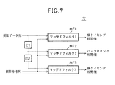
図7は、図6に示す相関演算部22の第1構成例を示すブロック図である。相関演算部22には、受信データ列を1サンプルタイミング遅らせる遅延素子D1と、この遅れた受信データ列をさらに1サンプルタイミング遅らせる遅延素子D2が設けられる。
そして、元の受信データ列、1サンプルタイミング遅れた受信データ列、及び2サンプルタイミング遅れた受信データ列に対して、同じ参照符号列との相関値を算出するマッチドフィルタMF1〜MF3を備えて構成してよい。
このようにして、あるタイミングにおける相関値と、このタイミングより1サンプル前のタイミングにおける相関値と、1サンプル後のタイミングにおける相関値を同時に算出することが可能となる。FIG. 7 is a block diagram illustrating a first configuration example of the
And it comprises the matched filters MF1 to MF3 for calculating the correlation value with the same reference code sequence for the original received data sequence, the received data sequence delayed by one sample timing, and the received data sequence delayed by 2 sample timings You can do it.
In this way, a correlation value at a certain timing, a correlation value at a timing one sample before this timing, and a correlation value at a timing after one sample can be calculated simultaneously.
図8は、図6に示す相関演算部の第2構成例を示すブロック図である。図2のマッチドフィルタと同様のマッチドフィルタの加算器Aの出力を1サンプルタイミング遅らせる遅延素子D1と、この遅れた出力をさらに1サンプルタイミング遅らせる遅延素子D2が設けられる。
加算器Aからは、参照符号列と受信データ列との間のタイミングを順次1サンプリング周期ずつずらした場合の相関値が出力されるので、遅延素子D1及びD2によって、あるタイミングにおける相関値と、このタイミングより1サンプル前のタイミングにおける相関値と、1サンプル後のタイミングにおける相関値を同時に出力することが可能となる。FIG. 8 is a block diagram illustrating a second configuration example of the correlation calculation unit illustrated in FIG. 6. A delay element D1 for delaying the output of the adder A of the matched filter similar to the matched filter of FIG. 2 by one sample timing and a delay element D2 for further delaying the delayed output by one sample timing are provided.
Since the adder A outputs the correlation value when the timing between the reference code string and the received data string is sequentially shifted by one sampling period, the correlation value at a certain timing is output by the delay elements D1 and D2. It is possible to simultaneously output the correlation value at the timing one sample before the timing and the correlation value at the timing one sample later.
図6に戻り、タイミング決定部24は、当該タイミングの相関電力値及び前後タイミングにおける相関電力値のうち、当該タイミングの相関電力値が所定閾値よりも大きなピーク値となるタイミングをパスタイミングとして決定し、そのときの当該タイミングの相関電力値をパスタイミング相関電力値とし、前及び後のタイミングにおける相関電力値を、それぞれ前タイミング相関電力値及び後タイミング相関電力値とする。なお以下の説明において、これら前タイミング相関電力値及び後タイミング相関電力値を総称して「隣接タイミング相関電力値」と記すことがある。
そしてタイミング決定部24は、フィンガー30a〜30dの逆拡散部にパスタイミングを出力するとともに、パスタイミング相関電力値、前タイミング相関電力値及び後タイミング相関電力値を補完調整部40へ出力する。Returning to FIG. 6, the
Then, the
補完調整部40は、受信データ列中の隣接するそれぞれのサンプルタイミングにおける信号値を補間して、各サンプルタイミングの中間の時刻における補間値、すなわち各サンプルタイミングから0.5サンプルずれた時刻における補間値を算出する前補間部62及び後補間部63とを備える。ここで前補間部62は受信データ列に対して0.5サンプル進んだ補間受信データ列を算出するために設けられ、後補間部62は受信データ列に対して0.5サンプル遅れた補間受信データ列を算出するために設けられる。
各補間部62及び63には、既知の補間フィルタのようなディジタルフィルタを使用してよい。このとき受信データ列のオーバサンプル数が充分大きければ、ディジタルフィルタのタップ数は小さくても良い。例えば2タップのディジタルフィルタを用いて、前後のタイミングの受信データを平均値をその間の時刻における補間としてもよい。The
Each
補完調整部40では、パスタイミング相関電力値と、前タイミング相関電力値及び後タイミング相関電力値との間を比較する。その比較結果に基づいてセレクタ61を制御して、元の受信データ列、元の受信データ列と比べて0.5サンプル進めた補間受信データ列、及び0.5サンプル遅らせた補間受信データ列のいずれを選択し、これらデータ列を切り替えてフィンガー30a〜30dへ出力する。
The
例えば補完調整部40は、前タイミング及び後タイミング相関電力値のいずれかのうちの一方である前タイミング相関電力値と、パスタイミング相関電力値との間の差、または、その比(パスタイミング相関電力値/前タイミング相関電力値)が所定閾値Th1よりも小さくなったとき、前補間部62を介して0.5サンプル進めた補間受信データ列をフィンガー30a〜30dへ出力することとしてよい。
または、前タイミング及び後タイミング相関電力値のいずれかのうちの他方である後タイミング相関電力値と、パスタイミング相関電力値との間の差、または、その比(パスタイミング相関電力値/後タイミング相関電力値)が所定閾値Th1よりも小さくなったとき、後補間部63を介して0.5サンプル遅らせた補間受信データ列をフィンガー30a〜30dへ出力することとしてよい。For example, the
Alternatively, the difference between the subsequent timing correlation power value, which is the other of the previous timing and the subsequent timing correlation power value, and the path timing correlation power value, or the ratio thereof (path timing correlation power value / post timing) When the correlation power value becomes smaller than the predetermined threshold Th1, the interpolated reception data sequence delayed by 0.5 samples may be output to the
そして、前タイミング及び後タイミング相関電力値のいずれについても、パスタイミング相関電力値との間の差、またはその比(パスタイミング相関電力値/前又は後タイミング相関電力値)が所定閾値Th1以上であるとき、元の受信データ列をフィンガー30a〜30dへ出力することとしてよい。
The difference between the path timing correlation power value and the ratio (path timing correlation power value / previous or subsequent timing correlation power value) of both the previous timing and the subsequent timing correlation power value is equal to or greater than the predetermined threshold Th1. In some cases, the original received data string may be output to the
閾値Th1は、実験、シミュレーションや理論値によって予め定めておく。ここで0.5サンプルだけずらした補間受信データ列は、受信信号を実際に受信した時刻に対応する最適なパスタイミングとタイミング決定部24が決定した離散的なパスタイミングとが、前後いずれかの方向に0.25〜0.5サンプル分ずれているときに、元の受信データ列よりも、参照符号との間の相関が高くなり、パスタイミングのずれが0.25サンプル分より小さい場合には、元の受信データ列の方が参照符号との間の相関は高い。
The threshold value Th1 is determined in advance by experiments, simulations, or theoretical values. Here, the interpolated received data sequence shifted by 0.5 samples has either an optimum path timing corresponding to the time when the received signal is actually received or a discrete path timing determined by the
したがって、例えば、パスタイミング相関電力値と隣接タイミング相関電力値との間の比較の際に、隣接タイミング相関電力値とパスタイミング相関電力値との差と比較される閾値Th1を定める場合には、予め実験等により逆拡散を行うタイミングを最適なパスタイミング(すなわち相関値が最大となるタイミング)から0.25サンプル分ずらせた相関値を算出し、これと最大相関値との差を閾値Th1として決定する。
また、隣接タイミング相関電力値とパスタイミング相関電力値との比と比較される閾値Th1を定める場合には、逆拡散を行うタイミングを最適パスタイミングから0.25サンプル分ずらせた相関値を算出し、これと最大相関値との比を閾値Th1として決定する。Therefore, for example, when the threshold Th1 to be compared with the difference between the adjacent timing correlation power value and the path timing correlation power value is determined in the comparison between the path timing correlation power value and the adjacent timing correlation power value, A correlation value is calculated in advance by deriving the despreading timing by 0.25 samples from the optimal path timing (that is, the timing at which the correlation value is maximized) by experiment or the like, and the difference between this and the maximum correlation value is set as a threshold Th1 decide.
In addition, when the threshold Th1 to be compared with the ratio between the adjacent timing correlation power value and the path timing correlation power value is determined, a correlation value obtained by dividing the despreading timing by 0.25 samples from the optimum path timing is calculated. The ratio between this and the maximum correlation value is determined as the threshold Th1.
このように閾値Th1を決定することによって、最適パスタイミングとタイミング決定部24が決定したパスタイミングとが、0.25〜0.5サンプル分ずれているときに補間受信データ列に逆拡散が施されることになる。この様子を図9を参照して説明する。
図9では、横軸にタイミング決定部24が決定したパスタイミングと最適なパスタイミングとのタイミング差を示し、縦軸に逆拡散部31が入力データ列を逆拡散するタイミングと最適なパスタイミングとのタイミング差を示している。
図示するように、最適なパスタイミングとタイミング決定部24が決定したパスタイミングとが、前方向に0〜0.25サンプル分及び後方向に0〜0.25サンプル分ずれた場合を除いた、ずれ量が0.25〜0.75サンプル分である場合に、逆拡散部31に補間受信データ列が入力されることにより、逆拡散タイミングと最適パスタイミングとの差が0.25サンプル分以下となり、補間なしの場合に比べて低減される。By determining the threshold value Th1 in this way, despreading is performed on the interpolated received data sequence when the optimum path timing and the path timing determined by the
In FIG. 9, the horizontal axis indicates the timing difference between the path timing determined by the
As shown in the figure, except for the case where the optimum path timing and the path timing determined by the
このとき元の受信データ列と、0.5サンプル進めた補間受信データ列、及び0.5サンプル遅らせた補間受信データ列との間のいずれを選択して逆拡散部31に入力するかの切替制御は、最大パス、すなわち受信強度が最も強いパスに関するパスタイミングにおける相関電力値と及びその隣接タイミング相関電力値だけについてのみ行ってもよい。これにより回路構成を小さくすることが可能となる。
そして、このように選択されたデータ列を、検出されたマルチパスの各パスについて逆拡散を行うフィンガー30a〜30dの全てに入力してもよい。この場合には最大パスの以外のパスタイミングでは、補完されたタイミングが実際のパスタイミングから遠くなる可能性もある。最大パスについて逆拡散を行うフィンガーにのみ選択されたデータ列を用い、他のパスについては元の受信データ列に対して逆拡散を行うこととしてもよい。At this time, switching between selecting the original received data sequence, the interpolated received data sequence advanced by 0.5 samples, and the interpolated received data sequence delayed by 0.5 samples to input to the
Then, the data string selected in this way may be input to all the
図10は、図6に示すCDMA受信装置の受信品質が向上したことを示すシミュレーション結果のグラフである。本グラフは、HSPDA方式におけるCQI用のSIR測定結果であり、静的な1つのパスについて、Ior/Ioc=30dBの受信状況において、受信データ列を4倍オーバーサンプルしたデータを用いて逆拡散した場合を想定している。図示するとおり、実際のパスタイミングがサンプルタイミング間にある場合におけるSIRが向上していることが分かる。 FIG. 10 is a graph of a simulation result indicating that the reception quality of the CDMA receiver shown in FIG. 6 is improved. This graph shows the SIR measurement results for CQI in the HSPDA system. In a static path, the received data string was despread using data that was oversampled four times in a reception situation of Ior / Ioc = 30 dB. Assume the case. As shown in the figure, it can be seen that the SIR is improved when the actual path timing is between the sample timings.
前補間部62及び後補間部63が作成する補間受信データ列と元の受信データ列とのずれ量は、0.5サンプル時間に限らず1サンプル時間よりも小さい他のサンプル時間(例えば0.4サンプル時間)としてもよい。
また前補間部62及び後補間部63は、パスタイミング相関電力値と隣接タイミング相関電力値との間の比較結果に応じて、元受信データ列から0.5サンプル時間及び0.25サンプル時間といった複数の時間分だけ段階的にずらした補間受信データ列を生成できるように構成してもよい。The amount of deviation between the interpolated reception data sequence created by the
Further, the
このとき、パスタイミング相関電力値と隣接タイミング相関電力値との間の比較の際に、隣接タイミング相関電力値とパスタイミング相関電力値との差や比と比較される閾値もまた、段階的に複数設定してもよい。
そして前補間部62及び後補間部63は、隣接タイミング相関電力値とパスタイミング相関電力値との間で比較したこれらの間の差や比が、段階的に設定された各閾値のいずれを超えるかにしたがって、段階的にタイミングをずらして補間受信データ列を生成することとしてよい。At this time, when comparing between the path timing correlation power value and the adjacent timing correlation power value, the threshold value to be compared with the difference or ratio between the adjacent timing correlation power value and the path timing correlation power value is also stepwise. A plurality may be set.
Then, the
例えば前補間部62及び後補間部63が、元受信データ列からタイミングを0.5サンプル時間及び0.25サンプル時間の2段階にずらして補間受信データ列を生成する場合を考える。このとき、補完調整部40がパスタイミング相関電力値と隣接タイミング相関電力値との間で比較する際に使用する閾値もまた、閾値Th2及びTh3の2段階に複数設定する。
このような閾値Th2及びTh3は、例えば、上記説明したように逆拡散を行うタイミングを最適パスタイミングからそれぞれ0.125及び0.375サンプル分ずらせた相関値と、最大相関値とを実験などにより導出して、これらの差や比を求めることにより決定する。For example, consider a case where the
Such thresholds Th2 and Th3 are obtained by, for example, experimenting with a correlation value obtained by shifting the despreading timing by 0.125 and 0.375 samples from the optimum path timing, respectively, and the maximum correlation value as described above. Derived and determined by obtaining these differences and ratios.
このとき図11A及び図11Bに示すように、パスタイミング相関電力値と隣接タイミング相関電力値との差ΔCは、最適パスタイミングから逆拡散を行うタイミングをからそれぞれ0.375サンプル時間だけずらせた場合よりも、0.125サンプル時間だけずらせた場合の方が大きい。したがって閾値Th2及びTh3の大小関係は、Th2<Th3となる。
したがって補完調整部40は、隣接タイミング相関電力値とパスタイミング相関電力値との間の差、または、その比(パスタイミング相関電力値/隣接タイミング相関電力値)が所定閾値Th2以下となったとき、前補間部62や後補間部63を介して0.5サンプルだけ前方や後方にずらせた補間受信データ列をフィンガー30a〜30dへ出力することとしてよい。At this time, as shown in FIGS. 11A and 11B, the difference ΔC between the path timing correlation power value and the adjacent timing correlation power value is obtained by shifting the despreading timing from the optimum path timing by 0.375 sample times, respectively. It is greater when shifted by 0.125 sample time. Therefore, the magnitude relationship between the threshold values Th2 and Th3 is Th2 <Th3.
Accordingly, the
また補完調整部40は、隣接タイミング相関電力値とパスタイミング相関電力値との間の差、または、その比が所定閾値Th2よりも大きくTh3以下のとき、前補間部62や後補間部63を介して0.25サンプルだけ前方や後方にずらせた補間受信データ列をフィンガー30a〜30dへ出力することとしてよい。
そして、隣接タイミング相関電力値とパスタイミング相関電力値との間の差、またはその比が所定閾値Th3以上であるとき、元の受信データ列をフィンガー30a〜30dへ出力することとしてよい。Further, when the difference between the adjacent timing correlation power value and the path timing correlation power value, or the ratio thereof is greater than the predetermined threshold Th2 and equal to or less than Th3, the
Then, when the difference between the adjacent timing correlation power value and the path timing correlation power value, or the ratio thereof is equal to or greater than the predetermined threshold Th3, the original received data sequence may be output to the
このように閾値Th2、Th3を決定することによって、最適パスタイミングとタイミング決定部24が決定したパスタイミングとが、0.125〜0.375サンプル分ずれているときに0.25サンプルだけずれた補間受信データ列に逆拡散が施され、0.375〜0.5サンプル分ずれているときに0.5サンプルだけずれた補間受信データ列に逆拡散が施されることになる。この様子を図12を参照して説明する。
By determining the threshold values Th2 and Th3 in this way, the optimal path timing and the path timing determined by the
図12では、横軸にタイミング決定部24が決定したパスタイミングと最適なパスタイミングとのタイミング差を示し、縦軸に逆拡散部31が入力データ列を逆拡散するタイミングと最適なパスタイミングとのタイミング差を示している。
1段階(0.5サンプル)のずれ量の補間受信データ列だけを使用した場合(図9を参照)と対比すると、2段階(0.25及び0.5サンプル)のずれ量の補間受信データ列を使用することによって、逆拡散タイミングと最適パスタイミングとの差を0.125サンプル分以下に低減することが可能になり、逆拡散タイミングを最適パスタイミングにより近づけることが可能となる。
また、閾値及び補間受信データ列のずらし量の段階数は、2段階に限られずさらに増やすことが可能である。段階数を増やすことによって逆拡散タイミングの補正精度をさらに上げることが可能となる。In FIG. 12, the horizontal axis indicates the timing difference between the path timing determined by the
Compared with the case of using only one stage (0.5 samples) of the amount of deviation reception data (see FIG. 9), two stages (0.25 and 0.5 samples) of the amount of interpolation reception data. By using a column, the difference between the despread timing and the optimum path timing can be reduced to 0.125 samples or less, and the despread timing can be made closer to the optimum path timing.
Further, the number of steps of the threshold value and the amount of shift of the interpolation received data string is not limited to two and can be further increased. By increasing the number of stages, it is possible to further improve the despread timing correction accuracy.
図13は、本発明の第2実施例によるCDMA受信装置の概略構成を示すブロック図である。本実施例では、パスサーチ部20が検出したマルチパスすべてのパスタイミングについて、パスサーチ検出タイミングの前後の相関電力値を用いて、逆拡散処理を施すデータ列を、元の受信データ列と補間受信データ列との間で切り替える。
このため全てのフィンガー部30a〜30dのそれぞれに対して、図6と同様の補間調整部40を設ける。そして補間調整部40による判定結果に従って、各パスごとに、逆拡散を施すデータ列を、元の受信データ列、その前後の補間受信データ列の間で切り替える。
なお、図においてタイミング決定部24から、各フィンガー部30a〜30dにそれぞれ設けられた補間調整部40に至る信号線を省略して示しているが、各補間調整部40は、図6を参照して上記説明した補間調整部40と同様に、タイミング決定部24から、パスタイミング相関電力値、前タイミング相関電力値及び後タイミング相関電力値を受信する。
本実施例は、図6の実施例に比べて回路規模が大きくなるが、特性改善量は大きい。FIG. 13 is a block diagram showing a schematic configuration of a CDMA receiver according to the second embodiment of the present invention. In the present embodiment, for all the multi-path timings detected by the
For this reason, the same
In the figure, signal lines from the
The circuit scale of this embodiment is larger than that of the embodiment of FIG. 6, but the characteristic improvement amount is large.
図14は、本発明の第3実施例によるCDMA受信装置の概略構成を示すブロック図である。本実施例では、補間調整部40による判定結果に従って、元の受信データ列及びその前後の補間受信データ列からセレクタ61により選択されたデータ列を、パスサーチ部20へフィードバック入力し、このデータ列を用いてパスサーチを行う。本構成によって補間されたデータ列を用いてパスタイミングを検出することが可能となり、参照符号列と間の相関値のピークを検出することを容易にする効果が期待できる。
FIG. 14 is a block diagram showing a schematic configuration of a CDMA receiver according to the third embodiment of the present invention. In this embodiment, the data sequence selected by the
図15は、本発明の第4実施例によるCDMA受信装置の概略構成を示すブロック図である。本実施例では、受信データ列を濾過するディジタルフィルタ42を用いて、受信データ列から補間受信データ列を生成する。そして、ディジタルフィルタ42のタップ係数を変更することによって、ディジタルフィルタ42からフィンガー30a〜30dへ出力するデータ列を、元の受信データ列、その前後にタイミングをずらせた補間受信データ列のいずれかから選択する。このためCDMA受信装置1は、補間調整部40による判定結果に従ってタップ係数を変更するタップ係数変更部41を備える。ディジタルフィルタのタップ係数を変えることにより、タイミングを変える手法自体は既知である。なお、CDMA受信装置1では、受信帯域を制限するために予め帯域制限フィルタを実装する場合があり、この場合には予め実装された帯域制限フィルタを、本構成のディジタルフィルタ42として使用することによって、簡易に本発明を実現することができる。
FIG. 15 is a block diagram showing a schematic configuration of a CDMA receiver according to the fourth embodiment of the present invention. In the present embodiment, an interpolated reception data string is generated from the reception data string using a digital filter 42 that filters the reception data string. Then, by changing the tap coefficient of the digital filter 42, the data sequence output from the digital filter 42 to the
図16は、本発明の第5実施例によるCDMA受信装置の概略構成を示すブロック図である。
本構成では、逆拡散部31への入力データ列を前方にずらす場合には前補間部62のみによる補間を行うが、後方にずらす処理を行う場合には、前補間部62によって逆拡散部31へ入力する受信データ列を1サンプル時間未満の所定時間だけ前方にずらすとともに、逆拡散タイミングを、パスサーチ部20が設定したタイミングよりも1サンプル遅らせる。
このために、CDMA受信装置1は、補間調整部40による判定結果に従って逆拡散部31へ入力するパスタイミングを変更するパスタイミング補正部43を備える。FIG. 16 is a block diagram showing a schematic configuration of a CDMA receiver according to the fifth embodiment of the present invention.
In this configuration, when the input data string to the
For this purpose, the
図6の構成では2つの補間部62及び63があるために、逆拡散部31による逆拡散タイミングは、パスサーチ部20によって検出された1つのパスタイミングに対して、前0.5サンプル及び後0.5サンプルの計1サンプル分だけ変動する可能性がある。
したがって、逆拡散タイミングがサンプルタイミングt1とt2の間の(t1+t2)/2であった場合に、同じパスタイミングに対してパスサーチ部20から異なるサンプルタイミングt1及びt2が入力されることが考えられるため、タイミングに係わる処理(例えば受信装置1が同じパスを継続した信号を受信しているか否かなど判断処理)が複雑化する。In the configuration of FIG. 6, since there are two
Therefore, when the despreading timing is (t1 + t2) / 2 between the sample timings t1 and t2, it is considered that different sample timings t1 and t2 are input from the
本実施例によれば、補間部による逆拡散タイミングの補正幅は0.5サンプルに低減されるので、同じパスタイミングに対して異なるサンプルタイミングが逆拡散部31に入力される可能性がなくなるのでタイミングに係わる処理を行うとき複雑性が減る。また、後補間部63を省略することができ回路規模面でも有利である。
なお、本実施例に代えて、0.5サンプル後ろにずらすための後補間部を備え、0.5サンプル前にずらす処理を行う場合には、後補間部によって逆拡散部31へ入力する受信データ列を0.5サンプル後にずらすとともに、パスタイミング補正部43を用いて、逆拡散タイミングを、パスサーチ部20が設定したタイミングよりも1サンプル早めてもよい。According to the present embodiment, since the correction width of the despreading timing by the interpolation unit is reduced to 0.5 samples, there is no possibility that different sample timings are input to the
Note that, instead of this embodiment, a post-interpolation unit for shifting 0.5 samples behind is provided, and when the process of shifting 0.5 samples before is performed, reception input to the
また図13〜図16に示した各実施例においても、前補間部62及び後補間部63は、図11及び図12を参照して説明したように、受信データ列からのずらし量を段階的に変更した補間受信データ列を生成してもよい。
Also, in each of the embodiments shown in FIGS. 13 to 16, the
以上、説明のみを目的として選択した好適な実施例を参照しながら、本発明を説明したが、当業者には本発明の趣旨および範囲から逸脱することなく、これら実施例の様々な変形、省略、および逸脱を、行なうことが可能であることは明らかである。また、クレームに使用される各用語は、明細書にて説明された実施例に記載された特定の意味に限定されるものではない。 Although the present invention has been described above with reference to preferred embodiments selected for purposes of illustration only, various modifications and omissions of these embodiments will occur to those skilled in the art without departing from the spirit and scope of the present invention. Obviously, and deviations can be made. The terms used in the claims are not limited to the specific meanings described in the embodiments described in the specification.
本発明は、直接拡散符号分割多元接続方式のようなCDMA通信方式を利用するCDMA受信装置及びCDMA受信方法に利用可能である。特に本発明は、このようなCDMA受信装置及びCDMA受信方法において受信データ列に逆拡散処理を行う逆拡散タイミングを最適化するための技術に好適に履行可能である。 The present invention can be applied to a CDMA receiving apparatus and a CDMA receiving method that use a CDMA communication method such as a direct spreading code division multiple access method. In particular, the present invention can be suitably implemented in a technique for optimizing the despreading timing for performing the despreading process on the received data string in such a CDMA receiving apparatus and CDMA receiving method.
Claims (7)
受信データ列を入力し、前記受信データ列と参照符号列の相関値がピークとなるサンプルタイミングであるパスタイミングを出力するとともに、前記パスタイミングに隣接したサンプルタイミングにおける前記相関値を隣接タイミング相関値として出力するパスサーチ部と、
前記受信データ列より、1サンプル時間未満の時間である所定サンプル時間分、時間をずらした補間受信データ列を生成する補間部を有し、前記パスタイミングにおける相関値と前記隣接タイミング相関値との比較結果に基づき、前記受信データ列または前記補間受信データ列のいずれかを切り替えて出力する補間調整部と、
前記パスタイミングにより前記補間調整部の出力を逆拡散する逆拡散部と、
を備えることを特徴とするCDMA受信装置。In a CDMA receiver that demodulates a received signal by applying a despreading process to the received signal using the same code string as the spreading code string,
A received data string is input, a path timing that is a sample timing at which a correlation value between the received data string and a reference code string reaches a peak, and the correlation value at a sample timing adjacent to the path timing is set as an adjacent timing correlation value A path search unit that outputs as
An interpolator that generates an interpolated received data sequence shifted by a predetermined sample time that is less than one sample time from the received data sequence, and a correlation value between the path timing and the adjacent timing correlation value An interpolation adjustment unit that switches and outputs either the received data string or the interpolated received data string based on the comparison result;
A despreading unit that despreads the output of the interpolation adjustment unit according to the path timing;
A CDMA receiving apparatus comprising:
受信データ列を入力し、前記受信データ列と参照符号列の相関値がピークとなるサンプルタイミングであるパスタイミングを出力するとともに、前記パスタイミングに隣接したサンプルタイミングにおける前記相関値を隣接タイミング相関値として出力するパスサーチ部と、
前記受信データ列より、1サンプル時間未満の時間である所定サンプル時間分、時間をずらした補間受信データ列を生成する補間部と、を有し、前記パスタイミングにおける相関値と前記隣接タイミング相関値との比較結果に基づき、補間が必要ない場合には、前記受信データ列を出力し、それ以外は、前記補間部によって前記補間受信データ列を出力することを特徴とする補間調整部と、
前記パスタイミングにより前記補間調整部の出力を逆拡散する逆拡散部と、
を備えることを特徴とするCDMA受信装置。In a CDMA receiver that demodulates a received signal by applying a despreading process to the received signal using the same code string as the spreading code string,
A received data string is input, a path timing that is a sample timing at which a correlation value between the received data string and a reference code string reaches a peak, and the correlation value at a sample timing adjacent to the path timing is set as an adjacent timing correlation value A path search unit that outputs as
An interpolator that generates an interpolated received data sequence shifted by a predetermined sample time that is a time less than one sample time from the received data sequence, and a correlation value at the path timing and the adjacent timing correlation value Based on the comparison result, and when the interpolation is not necessary, the received data sequence is output, otherwise, the interpolation adjustment unit characterized in that the interpolation received data sequence is output by the interpolation unit;
A despreading unit that despreads the output of the interpolation adjustment unit according to the path timing;
A CDMA receiving apparatus comprising:
該パスサーチ部が、このフィードバック入力されたデータ列を前記受信データ列として用いて前記パスタイミングを決定することを特徴とする請求項1又は2に記載のCDMA受信装置。The data string switched and output by the interpolation adjustment unit is fed back and input to the path search unit,
3. The CDMA receiving apparatus according to claim 1, wherein the path search unit determines the path timing using the data sequence input as feedback as the received data sequence. 4.
該ディジタルフィルタのタップ係数を変更して前記受信データ列と前記補間受信データ列との間の切り替え制御を行うタップ係数変更部と、を備えることを特徴とする請求項1又は2に記載のCDMA受信装置。A digital filter as the interpolation unit;
The CDMA according to claim 1, further comprising: a tap coefficient changing unit that changes a tap coefficient of the digital filter to perform switching control between the received data string and the interpolated received data string. Receiver device.
受信データ列を入力し、前記受信データ列と参照符号列の相関値がピークとなるサンプルタイミングであるパスタイミングを出力するとともに、前記パスタイミングに隣接したサンプルタイミングにおける前記相関値を隣接タイミング相関値として出力するパスサーチステップと、
前記受信データ列より、1サンプル時間未満の時間である所定サンプル時間分、時間をずらした補間受信データ列を生成し、前記パスタイミングにおける相関値と前記隣接タイミング相関値との比較結果に基づき、前記受信データ列または前記補間受信データ列を切り替えて出力する補間調整ステップと、
該補間調整ステップにより、切り替えて出力されたデータ列を、前記パスタイミングにより逆拡散する逆拡散ステップと、
を備えることを特徴とするCDMA受信方法。In a CDMA receiving method for demodulating a received signal by applying a despreading process to the received signal using the same code string as the spreading code string,
A received data string is input, a path timing that is a sample timing at which a correlation value between the received data string and a reference code string reaches a peak, and the correlation value at a sample timing adjacent to the path timing is set as an adjacent timing correlation value Path search step to output as
From the received data sequence, an interpolated received data sequence shifted by a predetermined sample time which is a time less than one sample time is generated, and based on a comparison result between the correlation value at the path timing and the adjacent timing correlation value, An interpolation adjustment step of switching and outputting the received data string or the interpolation received data string;
A despreading step of despreading the data sequence switched and output by the interpolation adjustment step according to the path timing;
A CDMA reception method comprising:
受信データ列を入力し、前記受信データ列と参照符号列の相関値がピークとなるサンプルタイミングであるパスタイミングを出力するとともに、前記パスタイミングに隣接したサンプルタイミングにおける前記相関値を隣接タイミング相関値として出力するパスサーチステップと、
前記パスタイミングにおける相関値と前記隣接タイミング相関値との比較結果に基づき、補間が必要ない場合には、前記受信データ列を出力し、それ以外は、前記受信データ列を1サンプル時間未満の時間である所定サンプル時間分、時間をずらした補間受信データ列を生成し、前記補間受信データ列を出力することを特徴とする補間調整ステップと、
該補間調整ステップにより出力されたデータ列を、前記パスタイミングにより逆拡散する逆拡散ステップと、
を備えることを特徴とするCDMA受信方法。In a CDMA receiving method for demodulating a received signal by applying a despreading process to the received signal using the same code string as the spreading code string,
A received data string is input, a path timing that is a sample timing at which a correlation value between the received data string and a reference code string reaches a peak, and the correlation value at a sample timing adjacent to the path timing is set as an adjacent timing correlation value Path search step to output as
Based on the comparison result between the correlation value at the path timing and the adjacent timing correlation value, the output of the received data string is output when interpolation is not necessary, and the received data string is set to a time shorter than one sample time otherwise. An interpolation adjustment step characterized by generating an interpolation reception data sequence shifted in time by a predetermined sample time, and outputting the interpolation reception data sequence;
A despreading step of despreading the data sequence output by the interpolation adjustment step according to the path timing;
A CDMA reception method comprising:
Applications Claiming Priority (1)
| Application Number | Priority Date | Filing Date | Title |
|---|---|---|---|
| PCT/JP2006/306897 WO2007116488A1 (en) | 2006-03-31 | 2006-03-31 | Cdma receiver and cdma receiving method |
Publications (2)
| Publication Number | Publication Date |
|---|---|
| JPWO2007116488A1 JPWO2007116488A1 (en) | 2009-08-20 |
| JP4724747B2 true JP4724747B2 (en) | 2011-07-13 |
Family
ID=38580797
Family Applications (1)
| Application Number | Title | Priority Date | Filing Date |
|---|---|---|---|
| JP2008509639A Active JP4724747B2 (en) | 2006-03-31 | 2006-03-31 | CDMA receiving apparatus and CDMA receiving method |
Country Status (4)
| Country | Link |
|---|---|
| US (1) | US8265123B2 (en) |
| EP (1) | EP2003789B1 (en) |
| JP (1) | JP4724747B2 (en) |
| WO (1) | WO2007116488A1 (en) |
Families Citing this family (25)
| Publication number | Priority date | Publication date | Assignee | Title |
|---|---|---|---|---|
| US8275082B2 (en) * | 2006-12-01 | 2012-09-25 | Broadcom Corporation | Method and system for delay locked loop for rake receiver |
| US8312551B2 (en) | 2007-02-15 | 2012-11-13 | Harris Corporation | Low level sequence as an anti-tamper Mechanism |
| US8170087B2 (en) * | 2007-05-10 | 2012-05-01 | Texas Instruments Incorporated | Correlation coprocessor |
| US8611530B2 (en) | 2007-05-22 | 2013-12-17 | Harris Corporation | Encryption via induced unweighted errors |
| US20090104357A1 (en) * | 2007-10-17 | 2009-04-23 | Dattilo Vincent P | Mutli-layer composite coloring coating process |
| US8363830B2 (en) | 2008-02-07 | 2013-01-29 | Harris Corporation | Cryptographic system configured to perform a mixed radix conversion with a priori defined statistical artifacts |
| US8320557B2 (en) | 2008-05-08 | 2012-11-27 | Harris Corporation | Cryptographic system including a mixed radix number generator with chosen statistical artifacts |
| US8325702B2 (en) | 2008-08-29 | 2012-12-04 | Harris Corporation | Multi-tier ad-hoc network in which at least two types of non-interfering waveforms are communicated during a timeslot |
| US8406276B2 (en) | 2008-12-29 | 2013-03-26 | Harris Corporation | Communications system employing orthogonal chaotic spreading codes |
| US8351484B2 (en) | 2008-12-29 | 2013-01-08 | Harris Corporation | Communications system employing chaotic spreading codes with static offsets |
| US8457077B2 (en) | 2009-03-03 | 2013-06-04 | Harris Corporation | Communications system employing orthogonal chaotic spreading codes |
| US8428102B2 (en) * | 2009-06-08 | 2013-04-23 | Harris Corporation | Continuous time chaos dithering |
| US8509284B2 (en) * | 2009-06-08 | 2013-08-13 | Harris Corporation | Symbol duration dithering for secured chaotic communications |
| US8428103B2 (en) | 2009-06-10 | 2013-04-23 | Harris Corporation | Discrete time chaos dithering |
| JP2011003970A (en) * | 2009-06-16 | 2011-01-06 | Fujitsu Ltd | Receiving apparatus, base station apparatus, and synchronization timing detection method |
| US8406352B2 (en) | 2009-07-01 | 2013-03-26 | Harris Corporation | Symbol estimation for chaotic spread spectrum signal |
| US8379689B2 (en) * | 2009-07-01 | 2013-02-19 | Harris Corporation | Anti-jam communications having selectively variable peak-to-average power ratio including a chaotic constant amplitude zero autocorrelation waveform |
| US8385385B2 (en) | 2009-07-01 | 2013-02-26 | Harris Corporation | Permission-based secure multiple access communication systems |
| US8369376B2 (en) | 2009-07-01 | 2013-02-05 | Harris Corporation | Bit error rate reduction in chaotic communications |
| US8428104B2 (en) | 2009-07-01 | 2013-04-23 | Harris Corporation | Permission-based multiple access communications systems |
| US8363700B2 (en) * | 2009-07-01 | 2013-01-29 | Harris Corporation | Rake receiver for spread spectrum chaotic communications systems |
| US8340295B2 (en) * | 2009-07-01 | 2012-12-25 | Harris Corporation | High-speed cryptographic system using chaotic sequences |
| US8848909B2 (en) | 2009-07-22 | 2014-09-30 | Harris Corporation | Permission-based TDMA chaotic communication systems |
| US8369377B2 (en) | 2009-07-22 | 2013-02-05 | Harris Corporation | Adaptive link communications using adaptive chaotic spread waveform |
| US8345725B2 (en) * | 2010-03-11 | 2013-01-01 | Harris Corporation | Hidden Markov Model detection for spread spectrum waveforms |
Citations (4)
| Publication number | Priority date | Publication date | Assignee | Title |
|---|---|---|---|---|
| JPH0964857A (en) * | 1995-08-25 | 1997-03-07 | Oki Electric Ind Co Ltd | Maximum correlation timing estimate circuit and receiver |
| JPH1032523A (en) * | 1996-07-15 | 1998-02-03 | Nec Corp | Receiving timing detection circuit for cdma receiver |
| JPH1141141A (en) * | 1997-05-21 | 1999-02-12 | Mitsubishi Electric Corp | Spread spectrum signal receiving method and device therefor |
| JP2001016136A (en) * | 1999-06-30 | 2001-01-19 | Nec Corp | Direct spread cdma receiver |
Family Cites Families (10)
| Publication number | Priority date | Publication date | Assignee | Title |
|---|---|---|---|---|
| GB2340352B (en) * | 1998-07-31 | 2003-05-07 | Roke Manor Research | Sampling means for use with rake receiver |
| JP3816684B2 (en) | 1999-02-24 | 2006-08-30 | 三菱電機株式会社 | Spread spectrum receiver |
| JP3322246B2 (en) * | 1999-07-21 | 2002-09-09 | 日本電気株式会社 | Path search apparatus and method |
| US6879623B2 (en) * | 2001-03-28 | 2005-04-12 | Motorola, Inc. | Method and apparatus for timing recovery in a communication device |
| JP3443113B2 (en) | 2001-08-08 | 2003-09-02 | 松下電器産業株式会社 | Wireless receiving apparatus and wireless receiving method |
| US7058369B1 (en) * | 2001-11-21 | 2006-06-06 | Pmc-Sierra Inc. | Constant gain digital predistortion controller for linearization of non-linear amplifiers |
| JP2003198427A (en) | 2001-12-28 | 2003-07-11 | Fujitsu Ltd | Cdma receiver |
| US7254185B2 (en) * | 2002-03-14 | 2007-08-07 | Mediatek Incorporation | Method for recovering a digital data content in a communication system and apparatus for performing the same |
| EP1376886A1 (en) * | 2002-06-17 | 2004-01-02 | Agilent Technologies, Inc. - a Delaware corporation - | Rake receiver delay line design |
| US7206335B2 (en) * | 2002-10-02 | 2007-04-17 | Interdigital Technology Corporation | Optimum interpolator method and apparatus for digital timing adjustment |
-
2006
- 2006-03-31 WO PCT/JP2006/306897 patent/WO2007116488A1/en active Application Filing
- 2006-03-31 JP JP2008509639A patent/JP4724747B2/en active Active
- 2006-03-31 EP EP06730845.2A patent/EP2003789B1/en not_active Expired - Fee Related
-
2008
- 2008-09-29 US US12/239,974 patent/US8265123B2/en active Active
Patent Citations (4)
| Publication number | Priority date | Publication date | Assignee | Title |
|---|---|---|---|---|
| JPH0964857A (en) * | 1995-08-25 | 1997-03-07 | Oki Electric Ind Co Ltd | Maximum correlation timing estimate circuit and receiver |
| JPH1032523A (en) * | 1996-07-15 | 1998-02-03 | Nec Corp | Receiving timing detection circuit for cdma receiver |
| JPH1141141A (en) * | 1997-05-21 | 1999-02-12 | Mitsubishi Electric Corp | Spread spectrum signal receiving method and device therefor |
| JP2001016136A (en) * | 1999-06-30 | 2001-01-19 | Nec Corp | Direct spread cdma receiver |
Also Published As
| Publication number | Publication date |
|---|---|
| WO2007116488A1 (en) | 2007-10-18 |
| EP2003789A1 (en) | 2008-12-17 |
| US8265123B2 (en) | 2012-09-11 |
| US20090022212A1 (en) | 2009-01-22 |
| EP2003789A4 (en) | 2011-06-01 |
| EP2003789B1 (en) | 2016-05-18 |
| JPWO2007116488A1 (en) | 2009-08-20 |
Similar Documents
| Publication | Publication Date | Title |
|---|---|---|
| JP4724747B2 (en) | CDMA receiving apparatus and CDMA receiving method | |
| EP1105977B1 (en) | Adaptive receiver for multipath propagation in a cdma communication system | |
| JP3831229B2 (en) | Propagation path characteristic estimation device | |
| EP1774670B1 (en) | Use of adaptive filters in cdma wireless systems employing pilot signals | |
| US7715463B2 (en) | Simple and robust digital code tracking loop for wireless communication systems | |
| JP4253703B2 (en) | Receiver | |
| JP3443113B2 (en) | Wireless receiving apparatus and wireless receiving method | |
| US20080095217A1 (en) | Correlation detection method, correlation detection apparatus, transmission diversity detection method and transmission diversity detection circuit | |
| KR101506747B1 (en) | Method and apparatus for efficient signal interpolation | |
| JP3386738B2 (en) | Frame synchronization circuit and frame timing extraction method | |
| JP3322243B2 (en) | Direct spread CDMA receiver | |
| JP3884218B2 (en) | Spread spectrum receiver | |
| JP3816684B2 (en) | Spread spectrum receiver | |
| US6959035B2 (en) | Post-correlation interpolation for delay locked loops | |
| JP2991236B1 (en) | Error estimation apparatus for direct-sequence reception data and direct-sequence reception apparatus | |
| JP2000091973A (en) | Rake synthesis circuit | |
| US20030231703A1 (en) | Rake receiver delay line design | |
| US6865219B2 (en) | Apparatus and method of circular group-wise parallel interference cancellation for multi-rate DS-CDMA system | |
| WO2005013505A1 (en) | Reception device | |
| JP2009239977A (en) | Communication control device and method based on moving speed | |
| JP2007116732A (en) | Communication control apparatus and method based on moving speed | |
| US20070041430A1 (en) | Reception device | |
| JP2000353981A (en) | Device for estimating direct spread received data and direct spread receiver | |
| JP2002237765A (en) | Receiving circuit |
Legal Events
| Date | Code | Title | Description |
|---|---|---|---|
| A131 | Notification of reasons for refusal |
Free format text: JAPANESE INTERMEDIATE CODE: A131 Effective date: 20100824 |
|
| A521 | Written amendment |
Free format text: JAPANESE INTERMEDIATE CODE: A523 Effective date: 20101025 |
|
| A131 | Notification of reasons for refusal |
Free format text: JAPANESE INTERMEDIATE CODE: A131 Effective date: 20110104 |
|
| A521 | Written amendment |
Free format text: JAPANESE INTERMEDIATE CODE: A523 Effective date: 20110307 |
|
| TRDD | Decision of grant or rejection written | ||
| A01 | Written decision to grant a patent or to grant a registration (utility model) |
Free format text: JAPANESE INTERMEDIATE CODE: A01 Effective date: 20110405 |
|
| A01 | Written decision to grant a patent or to grant a registration (utility model) |
Free format text: JAPANESE INTERMEDIATE CODE: A01 |
|
| A61 | First payment of annual fees (during grant procedure) |
Free format text: JAPANESE INTERMEDIATE CODE: A61 Effective date: 20110411 |
|
| FPAY | Renewal fee payment (event date is renewal date of database) |
Free format text: PAYMENT UNTIL: 20140415 Year of fee payment: 3 |
|
| R150 | Certificate of patent or registration of utility model |
Ref document number: 4724747 Country of ref document: JP Free format text: JAPANESE INTERMEDIATE CODE: R150 Free format text: JAPANESE INTERMEDIATE CODE: R150 |