JP4723507B2 - RFID security algorithm - Google Patents
RFID security algorithm Download PDFInfo
- Publication number
- JP4723507B2 JP4723507B2 JP2006539517A JP2006539517A JP4723507B2 JP 4723507 B2 JP4723507 B2 JP 4723507B2 JP 2006539517 A JP2006539517 A JP 2006539517A JP 2006539517 A JP2006539517 A JP 2006539517A JP 4723507 B2 JP4723507 B2 JP 4723507B2
- Authority
- JP
- Japan
- Prior art keywords
- tag
- reader
- signal
- antennas
- tags
- Prior art date
- Legal status (The legal status is an assumption and is not a legal conclusion. Google has not performed a legal analysis and makes no representation as to the accuracy of the status listed.)
- Expired - Fee Related
Links
Images


Classifications
-
- G—PHYSICS
- G06—COMPUTING; CALCULATING OR COUNTING
- G06K—GRAPHICAL DATA READING; PRESENTATION OF DATA; RECORD CARRIERS; HANDLING RECORD CARRIERS
- G06K17/00—Methods or arrangements for effecting co-operative working between equipments covered by two or more of main groups G06K1/00 - G06K15/00, e.g. automatic card files incorporating conveying and reading operations
-
- G—PHYSICS
- G06—COMPUTING; CALCULATING OR COUNTING
- G06K—GRAPHICAL DATA READING; PRESENTATION OF DATA; RECORD CARRIERS; HANDLING RECORD CARRIERS
- G06K7/00—Methods or arrangements for sensing record carriers, e.g. for reading patterns
- G06K7/08—Methods or arrangements for sensing record carriers, e.g. for reading patterns by means detecting the change of an electrostatic or magnetic field, e.g. by detecting change of capacitance between electrodes
-
- G—PHYSICS
- G06—COMPUTING; CALCULATING OR COUNTING
- G06K—GRAPHICAL DATA READING; PRESENTATION OF DATA; RECORD CARRIERS; HANDLING RECORD CARRIERS
- G06K7/00—Methods or arrangements for sensing record carriers, e.g. for reading patterns
- G06K7/10—Methods or arrangements for sensing record carriers, e.g. for reading patterns by electromagnetic radiation, e.g. optical sensing; by corpuscular radiation
- G06K7/10009—Methods or arrangements for sensing record carriers, e.g. for reading patterns by electromagnetic radiation, e.g. optical sensing; by corpuscular radiation sensing by radiation using wavelengths larger than 0.1 mm, e.g. radio-waves or microwaves
- G06K7/10019—Methods or arrangements for sensing record carriers, e.g. for reading patterns by electromagnetic radiation, e.g. optical sensing; by corpuscular radiation sensing by radiation using wavelengths larger than 0.1 mm, e.g. radio-waves or microwaves resolving collision on the communication channels between simultaneously or concurrently interrogated record carriers.
- G06K7/10029—Methods or arrangements for sensing record carriers, e.g. for reading patterns by electromagnetic radiation, e.g. optical sensing; by corpuscular radiation sensing by radiation using wavelengths larger than 0.1 mm, e.g. radio-waves or microwaves resolving collision on the communication channels between simultaneously or concurrently interrogated record carriers. the collision being resolved in the time domain, e.g. using binary tree search or RFID responses allocated to a random time slot
- G06K7/10039—Methods or arrangements for sensing record carriers, e.g. for reading patterns by electromagnetic radiation, e.g. optical sensing; by corpuscular radiation sensing by radiation using wavelengths larger than 0.1 mm, e.g. radio-waves or microwaves resolving collision on the communication channels between simultaneously or concurrently interrogated record carriers. the collision being resolved in the time domain, e.g. using binary tree search or RFID responses allocated to a random time slot interrogator driven, i.e. synchronous
-
- G—PHYSICS
- G08—SIGNALLING
- G08B—SIGNALLING OR CALLING SYSTEMS; ORDER TELEGRAPHS; ALARM SYSTEMS
- G08B13/00—Burglar, theft or intruder alarms
- G08B13/22—Electrical actuation
- G08B13/24—Electrical actuation by interference with electromagnetic field distribution
- G08B13/2402—Electronic Article Surveillance [EAS], i.e. systems using tags for detecting removal of a tagged item from a secure area, e.g. tags for detecting shoplifting
- G08B13/2451—Specific applications combined with EAS
- G08B13/2462—Asset location systems combined with EAS
-
- G—PHYSICS
- G08—SIGNALLING
- G08B—SIGNALLING OR CALLING SYSTEMS; ORDER TELEGRAPHS; ALARM SYSTEMS
- G08B13/00—Burglar, theft or intruder alarms
- G08B13/22—Electrical actuation
- G08B13/24—Electrical actuation by interference with electromagnetic field distribution
- G08B13/2402—Electronic Article Surveillance [EAS], i.e. systems using tags for detecting removal of a tagged item from a secure area, e.g. tags for detecting shoplifting
- G08B13/2465—Aspects related to the EAS system, e.g. system components other than tags
- G08B13/2468—Antenna in system and the related signal processing
- G08B13/2474—Antenna or antenna activator geometry, arrangement or layout
-
- G—PHYSICS
- G08—SIGNALLING
- G08B—SIGNALLING OR CALLING SYSTEMS; ORDER TELEGRAPHS; ALARM SYSTEMS
- G08B13/00—Burglar, theft or intruder alarms
- G08B13/22—Electrical actuation
- G08B13/24—Electrical actuation by interference with electromagnetic field distribution
- G08B13/2402—Electronic Article Surveillance [EAS], i.e. systems using tags for detecting removal of a tagged item from a secure area, e.g. tags for detecting shoplifting
- G08B13/2465—Aspects related to the EAS system, e.g. system components other than tags
- G08B13/248—EAS system combined with another detection technology, e.g. dual EAS and video or other presence detection system
-
- G—PHYSICS
- G08—SIGNALLING
- G08B—SIGNALLING OR CALLING SYSTEMS; ORDER TELEGRAPHS; ALARM SYSTEMS
- G08B13/00—Burglar, theft or intruder alarms
- G08B13/22—Electrical actuation
- G08B13/24—Electrical actuation by interference with electromagnetic field distribution
- G08B13/2402—Electronic Article Surveillance [EAS], i.e. systems using tags for detecting removal of a tagged item from a secure area, e.g. tags for detecting shoplifting
- G08B13/2465—Aspects related to the EAS system, e.g. system components other than tags
- G08B13/2485—Simultaneous detection of multiple EAS tags
-
- G—PHYSICS
- G08—SIGNALLING
- G08B—SIGNALLING OR CALLING SYSTEMS; ORDER TELEGRAPHS; ALARM SYSTEMS
- G08B13/00—Burglar, theft or intruder alarms
- G08B13/22—Electrical actuation
- G08B13/24—Electrical actuation by interference with electromagnetic field distribution
- G08B13/2402—Electronic Article Surveillance [EAS], i.e. systems using tags for detecting removal of a tagged item from a secure area, e.g. tags for detecting shoplifting
- G08B13/2465—Aspects related to the EAS system, e.g. system components other than tags
- G08B13/2488—Timing issues, e.g. synchronising measures to avoid signal collision, with multiple emitters or a single emitter and receiver
-
- G—PHYSICS
- G08—SIGNALLING
- G08C—TRANSMISSION SYSTEMS FOR MEASURED VALUES, CONTROL OR SIMILAR SIGNALS
- G08C17/00—Arrangements for transmitting signals characterised by the use of a wireless electrical link
Landscapes
- Physics & Mathematics (AREA)
- Engineering & Computer Science (AREA)
- General Physics & Mathematics (AREA)
- Automation & Control Theory (AREA)
- Electromagnetism (AREA)
- Computer Security & Cryptography (AREA)
- Theoretical Computer Science (AREA)
- Health & Medical Sciences (AREA)
- Toxicology (AREA)
- Artificial Intelligence (AREA)
- Computer Vision & Pattern Recognition (AREA)
- Computer Networks & Wireless Communication (AREA)
- Multimedia (AREA)
- General Health & Medical Sciences (AREA)
- Signal Processing (AREA)
- Burglar Alarm Systems (AREA)
- Radar Systems Or Details Thereof (AREA)
- Variable-Direction Aerials And Aerial Arrays (AREA)
- Near-Field Transmission Systems (AREA)
Abstract
Description
本発明は、防御領域内の物品管理を行なう無線周波数識別システムの利用に関し、より具体的には、防御領域からの物品の無許可持ち出しを検知する技術に関する。 The present invention relates to the use of a radio frequency identification system that manages articles in a defense area, and more specifically to a technique for detecting unauthorized removal of articles from the defense area.
無線周波数識別(RFID)技術は、輸送、製造、廃棄物管理、郵便物追跡、航空手荷物照合、および高速道路通行料管理を含むような実質的にあらゆる産業において広く利用されている。RFIDシステムは往々にして、図書館や小売店等の防御領域からの物品の無許可持ち出しを予防すべく利用される。 Radio frequency identification (RFID) technology is widely used in virtually every industry, including transportation, manufacturing, waste management, mail tracking, air baggage verification, and highway toll management. RFID systems are often used to prevent unauthorized removal of items from defense areas such as libraries and retail stores.
RFIDシステムは往々にして、防御対象である物品に取付けられたRFIDタグを検知するために防御領域の出口の近くに設置された検問ゾーンまたは通路を含んでいる。各々のタグは通常、タグが添付されている物品を一意に識別する情報を含んでいる。物品は、書籍、製造物、車両、動物または個人、あるいは、実質的に他の任意の有形物であってよい。特定の用途により必要に応じて、追加的なデータを物品に提供してもよい。 RFID systems often include an interrogation zone or passage located near the exit of the defense area to detect RFID tags attached to the item being protected. Each tag typically includes information that uniquely identifies the item to which the tag is attached. The article may be a book, product, vehicle, animal or individual, or virtually any other tangible object. Additional data may be provided to the article as required by the particular application.
タグを検知するために、RFリーダーはアンテナを介してRF信号を出力して、検問通路内に電磁場を生成する。電磁場は、通路内のタグを活性化する。これにより、タグは特性応答を生成する。特に、一度タグが活性化されると、所定のプロトコルを用いて各タグが通信することにより、RFIDリーダーは通路内の1個以上のタグから識別情報を受信することができる。通信により、物品の持ち出しが許可を得ていないことが示されるとき、RFIDシステムは、音響警報を鳴らす、出口ゲートを閉鎖する等、何らかの適切なセキュリティ措置を起動する。 In order to detect the tag, the RF reader outputs an RF signal through the antenna to generate an electromagnetic field in the interrogation path. The electromagnetic field activates the tag in the passage. This causes the tag to generate a characteristic response. In particular, once a tag is activated, each tag communicates using a predetermined protocol, allowing the RFID reader to receive identification information from one or more tags in the passage. When the communication indicates that the taking of the item is not authorized, the RFID system activates any appropriate security measures such as sounding an audible alarm or closing the exit gate.
検問通路内に存在する物品がチェックアウトされているか否かを判定する大部分の方法は、第一に検問フィールド内の各タグを個別に検知して識別し、次いで識別されたタグに付随する物品の状態を調べて判定することにより決まる。いくつかの方法は、例えば、各タグの連続番号を判定し、次いで識別された連続番号に付随する物品の状態を判定するために、データベースにアクセスする。他の技術では、一度連続番号が判定されると、識別されたタグに対しコマンドを発行することが必要となる。 Most methods for determining whether an article that is present in an inspection passage is checked out first detects and identifies each tag in the inspection field individually, and then accompanies the identified tag This is determined by examining the state of the article. Some methods, for example, determine the serial number of each tag and then access the database to determine the state of the article associated with the identified serial number. Other techniques require that a command be issued for the identified tag once the serial number is determined.
この処理は、特にいくつかのタグが検問フィールド内に存在する場合、時間を要する場合がある。例えば、完全なタグ連続番号を得ようとするために、一度に1個のタグしか応答することができなくなる。複数のタグが一度に応答すると、衝突が起き、受信したデータは無効となり、どのタグの連続番号も得ることができなくなる。これを解決すべく、いくつかのシステムは、全てのタグから応答があるまで、各タグに対し異なるタイムスロットで応答することを要求する衝突防止処理を用いる。この処理で追加される遅延時間は、客が極めて短い時間しか検問通路内にいないため、出口制御システムでは好ましくない。また、各々の客が複数の書籍を抱えている可能性がある。書籍のすべてがチェックアウトされたか否かを判定するために要する時間は往々にして、客が通路で費やす時間よりはるかに長い。 This process can be time consuming, especially if several tags are present in the query field. For example, in order to obtain a complete tag sequence number, only one tag can respond at a time. If a plurality of tags respond at the same time, a collision occurs, the received data becomes invalid, and the serial number of any tag cannot be obtained. To solve this, some systems use an anti-collision process that requires each tag to respond in a different time slot until there is a response from all tags. The delay time added by this process is undesirable in the exit control system because the customer is only in the interrogation path for a very short time. In addition, each customer may have a plurality of books. The time required to determine whether all of a book has been checked out is often much longer than the time a customer spends in the aisle.
一般に、本発明は無線周波識別タグを検知する無線周波数識別(RFID)システムに関する。より具体的に、本発明は、例えば図書館から書籍その他の物品を持ち出すような、防御施設からの物品の無許可持ち出しを検知するRF出口制御システムに関する。一連のアンテナを設置して、防御領域の出口の付近に位置する検問通路を生成する。RFIDタグは、防御対象の物品に取り付けられる。ある例証的なシステムにおいて、各々のタグは、タグが添付されている物品を一意に識別する情報および当該物品を施設から持ち出す許可が与えられているか否かに関するステータス情報を含んでいる。タグを検知するために、RFリーダーはアンテナを介してRF信号を出力して検問通路内に電磁場を生成する。RFリーダーは、単一のポートから分配器/結合器経由で複数のアンテナへRF電波を出力する。このようにして、送受信器ポートを1個だけ備えた単一RFリーダーは、同時に複数のアンテナを介して尋問する。電磁場がタグを活性化させ、順々にタグが特性応答を生成する。RFリーダーは単一の送受信器ポート経由でタグ情報を受信し、物品の持ち出しが許可されているか否かをRF出口制御システムが判定する。物品の持ち出しが許可されていないとき、出口制御システムは、音響警報の出力、出口ゲートの閉鎖等、何らかの適切なセキュリティ措置を起動する。 In general, the present invention relates to a radio frequency identification (RFID) system that detects radio frequency identification tags. More specifically, the present invention relates to an RF exit control system that detects unauthorized removal of items from a defensive facility, such as taking books or other items from a library. Install a series of antennas to create an interrogation passage located near the exit of the defense area. The RFID tag is attached to an article to be protected. In one illustrative system, each tag includes information that uniquely identifies the item to which the tag is attached and status information regarding whether the item is authorized to be taken out of the facility. In order to detect the tag, the RF reader outputs an RF signal through the antenna to generate an electromagnetic field in the interrogation path. The RF reader outputs RF radio waves from a single port to a plurality of antennas via a distributor / coupler. In this way, a single RF reader with only one transceiver port interrogates via multiple antennas simultaneously. The electromagnetic field activates the tag, which in turn generates a characteristic response. The RF reader receives the tag information via a single transceiver port and the RF exit control system determines whether the item is allowed to be taken out. When the item is not allowed to be taken out, the exit control system activates any appropriate security measures, such as outputting an audible alarm, closing the exit gate, etc.
本発明の一実施形態における出口制御システムは、1個以上の検問通路を提供すべく設置された複数の無線周波数(RF)アンテナと、当該複数のアンテナに接続されたRFリーダーとを含み、当該RFリーダーが、各々のアンテナRF電波を提供して、当該検問通路内に検問フィールドを生成する送受信器(T/R)ポートを備えている。システムは更に、上記RFリーダーから上記RF電波を受信して、上記複数のアンテナの各々へ上記RF電波を複数のアンテナ駆動信号の形で配信する分配器を含んでいる。 An exit control system in one embodiment of the present invention includes a plurality of radio frequency (RF) antennas installed to provide one or more interrogation paths, and an RF reader connected to the plurality of antennas, The RF reader includes a transceiver (T / R) port that provides each antenna RF radio wave and generates an interrogation field within the interrogation path. The system further includes a distributor that receives the RF radio waves from the RF reader and distributes the RF radio waves to each of the plurality of antennas in the form of a plurality of antenna drive signals.
別の実施形態における方法は、RFリーダーの単一の送受信器(T/R)ポートから、
無線周波数(RF)出力信号を生成するステップと、当該RF出力信号を複数のアンテナ
駆動信号に分割するステップと、1個以上の検問通路内に検問フィールドを生成するため
に、上記アンテナ駆動信号を複数のアンテナへ配信するステップとを含んでいる。本方法は更に、上記検問フィールド内に存在する少なくとも1個のタグに応答して、上記アンテナを介して1個以上の入力信号を生成するステップと、当該入力信号を結合入力信号に結合させるステップと、当該結合入力信号を上記RFリーダーのT/Rポートに提供するステップとを含むことができる。
In another embodiment, the method includes: From a single transceiver (T / R) port of the RF reader,
Generating a radio frequency (RF) output signal; dividing the RF output signal into a plurality of antenna drive signals; and generating an interrogation field in one or more interrogation paths. Delivering to a plurality of antennas. The method further includes generating one or more input signals via the antenna in response to at least one tag present in the interrogation field, and combining the input signal with a combined input signal. And providing the combined input signal to a T / R port of the RF reader.
別の実施形態におけるコンピュータ可読媒体は、プロセッサに、複数の検問通路のいずれかの内に少なくとも1個のタグが存在することを示すタグ検知信号を単一のリーダーから受信させ、上記いずれかの検問通路内に少なくとも1人の客が存在することを示す客信号を受信させ、一定時間内にタグ検知信号および客信号を受信すると警報信号を出力させる命令を含む。当該コンピュータ可読媒体は更に、プロセッサに、上記タグ検知信号または上記客信号のいずれかを受信するとタイマーを始動させ、タイマーの終了前に上記タグ検知信号または上記客信号のもう一方を受信すると、警報信号を出力させる命令を含むことができる。 In another embodiment, a computer-readable medium causes a processor to receive a tag detection signal from a single reader indicating that there is at least one tag in any of the plurality of interrogation paths, and any of the above A command for receiving a customer signal indicating that there is at least one customer in the inspection passage and outputting a warning signal when the tag detection signal and the customer signal are received within a predetermined time is included. The computer readable medium further causes the processor to start a timer upon receiving either the tag detection signal or the customer signal and to receive an alarm when receiving the other of the tag detection signal or the customer signal before the timer expires. Instructions for outputting signals can be included.
本発明の一つ以上の実施形態の詳細を、添付図面および下記の記述により説明する。本発明の他の特徴、目的および利点は、下記の記述および図面、並びに請求項から明らかになる。 The details of one or more embodiments of the invention are set forth in the accompanying drawings and the description below. Other features, objects, and advantages of the invention will be apparent from the description and drawings, and from the claims.
一般に、本明細書において、無線周波数識別(RFID)タグを検知する技術について記載している。より具体的に、本記載は、防御領域からの物品の無許可の持ち出しを検知するRF出口制御システムに利用する技術を対象としている。防御領域とは通常、例えば図書館における書籍または小売店における商品のように、物品の持ち出しに許可が必要な種類のエリアである。施設内の各物品はRFIDタグを含んでいて、このタグが添付された物品を一意に識別することができる。また、本発明の目的から、RFIDタグは、物品の持ち出しが許可されているか否かを示すステータス情報も含んでいる。RFIDタグは、改ざん防止に役立つべく、実質的にタグが見えないように物品内部に埋め込むことができる。出口制御システムは、施設からの物品の持ち出しが許可されている(例えば、書籍が図書館の客またはスタッフ担当者により適切にチェックアウトされている)か否かを判定し、適切でないとき、警報を動作させる。 In general, this specification describes techniques for detecting radio frequency identification (RFID) tags. More specifically, the present description is directed to a technique used in an RF exit control system that detects unauthorized removal of an article from a defense area. A defensive area is usually the type of area that requires permission to take out an item, such as a book in a library or a product in a retail store. Each item in the facility includes an RFID tag, and the item to which the tag is attached can be uniquely identified. For the purposes of the present invention, the RFID tag also includes status information indicating whether or not the item is allowed to be taken out. The RFID tag can be embedded inside the article so that the tag is substantially invisible to help prevent tampering. The exit control system determines if the item is allowed to be taken out of the facility (eg, the book is properly checked out by a library customer or staff member) and alerts when it is not appropriate Make it work.
図1は、無線周波数識別(RFID)システム10を示すブロック図である。出口制御システム5は、防御領域7からの物品の無許可持ち出しを検知する。説明の都合上、防御領域は図書館、物品はチェックアウト対象である書籍その他の物品であると仮定する。本システムは、施設からの無許可持ち出しを防止すべくチェックイン状態タグを検知することに関して記載されているが、本発明がこれに限定されず、本明細書に記載する技術がRFIDシステムを用いる特定のアプリケーションに依存しない点を理解されたい。例えば、本システムを他の種類のステータスまたは種別情報を検査するために用いても本発明の範囲から逸脱しない。
FIG. 1 is a block diagram illustrating a radio frequency identification (RFID)
出口制御システム5は、防御領域7の出口付近に配置された検問ゾーンまたは通路を規定する格子9Aおよび9Bを含んでいる。格子9Aおよび9Bは、タグが取り付けられた物品の持ち出しが許可されているか否かを決定するために、RFIDタグが通路を通過する際に尋問するためのアンテナを含んでいる。以下に詳述するように、出口制御システム5は、単一のRFリーダーを利用して複数のアンテナを駆動する。タグを検知するために、RFリーダーは、アンテナからRF電波を出力して検問通路内に電磁場を生成する。RFリーダーは、単一のポートから分配器/結合器経由で複数のアンテナへRF電波を出力する。このようにして、送受信器ポートを1個だけ備えた単一のRFリーダーが複数のアンテナを使って通路へ同時に尋問する。アンテナからの電磁場がタグを活性化させ、順々にタグが特性応答を生成する。RFリーダーが単一の送受信器ポート経由でタグ情報を受信し、物品の持ち出しが許可されているか否かをRF出口制御システムが判定する。物品の持ち出しが許可されていない場合、出口制御システムは、音響警報を鳴らす、出口ゲートを閉鎖する等、何らかの適切なセキュリティ措置を起動する。
The
また、全体的なRFIDシステム10は、防御領域7内に多数の「スマート保管領域」12を含むことができる。例えば、開放棚12A、スマートカート12C、デスクトップ・リーダー12Eその他の領域がある。各々のスマート保管領域12は、施設全体にわたって物品の追跡を可能にするタグ尋問機能を含んでいる。例えば、図書館の設定において、書籍は、チェックイン後スマートカート12Cに搭載されて棚12Aへ向かうまで追跡することができる。
The
RFIDタグ自体は、本発明の範囲から逸脱することなく、任意の形状をとることができる。市販のRFIDタグの例として、ミネソタ州セントポール(St.Paul,MN)のスリーエム(3M)社から販売されている3M(商標)RFIDタグ、あるいはテキサス州ダラス(Dallas,TX)のテキサス・インスツルメンツ(Texas Instruments)社から販売されている「タグイット(Tag−it)」RFIDトランスポンダがある。RFIDタグは通常、当分野では公知の方法で、ソース源からのRFエネルギーと後方散乱するRFエネルギーとを受信するアンテナに動作可能に接続される集積回路を含んでいる。後方散乱するRFエネルギーは、RFIDタグとこれに付随する物品に関する情報を得るために、RFIDシステム10内の検問装置が受信可能な信号を出力する。
The RFID tag itself can take any shape without departing from the scope of the present invention. Examples of commercially available RFID tags include 3M ™ RFID tags sold by 3M (St. Paul, MN) or Texas Instruments, Dallas, TX. There is a “Tag-it” RFID transponder sold by (Texas Instruments). An RFID tag typically includes an integrated circuit that is operatively connected to an antenna that receives RF energy from a source source and backscattered RF energy in a manner known in the art. The backscattered RF energy outputs a signal that can be received by an interrogator in the
物品管理システム14は、施設内の各々の物品に関するタグ情報の集中データベースを提供する。物品管理システム14は、ネットワークを構成するか、または1台以上のコンピュータに別途接続されていて、図書館司書等の個人がさまざまな場所で、これらの物品に関するデータにアクセスすることができる。例えば、ユーザは書籍等、特定の物品の所在地およびステータス情報を要求することができる。物品管理システム14は、データベースから物品情報を取り出して、当該物品がスマート保管領域の一ヶ所に置かれた最後の位置をユーザに報告することができる。状況に応じて、本システムは、データベースが示す場所に物品が存在することを確認すべく、物品の現在位置を再ポーリングまたは別途再取得することができる。
The
図2に、RFID出口制御システム5の例証的な実施形態のより詳細なブロック図を示す。図に示すように、出口制御システム5は、本明細書に記載する技術に従い、RFリーダー20の1個のポートと複数のアンテナとの間でデータを送信及び/又は受信すべく構成される。
FIG. 2 shows a more detailed block diagram of an exemplary embodiment of the RFID
より具体的に、出口制御システム5は、複数の検問ゾーン40Aおよび40Bを提供すべく配置されたアンテナ8A、8B、および8C(集合的に「アンテナ8」と称する)を含んでいる。各々のアンテナ8A〜Cには、当該アンテナがRFリーダー20および最終的にコントローラ14に接続される付随チューナ18A〜Cを含んでいる。図2は、システム10が3個のアンテナ8A〜8Cおよび2個の検問ゾーン40A、40Bを含むように示しているが、施設の必要に応じて出口制御システム5は任意の個数の検問ゾーンを提供すべく設定された任意の個数のアンテナを含むことができることを理解されたい。
More specifically, the
出口制御システム5は、許容周波数変動が±7kHzである13.56MHz等の電磁スペクトルの周波数範囲で動作する。この周波数範囲は、産業、科学、および医療(ISM)用途で多く用いられる。しかし、RFID用途で他の周波数を用いてもよく、また本発明はこれに限定されない。
The
アンテナ8は、検問通路40内の少なくとも特定の強さの電磁場を生成すべく設計することができる。これには一つ以上の理由で利点があり、所望のステータスを有するタグ、例えば図書館用途でチェックイン状態タグを検知できる可能性を向上させることも含まれる。一実施形態において、アンテナ8が生成する電磁場は、通路40のRFタグにエネルギーを与えることに使用される。各々のRFタグで誘導されるエネルギー量は、タグ・ループを通過する磁場の強さに比例する。従って、アンテナ8は、115dBuA/m等、RFタグにエネルギーを付与するための閾値の強さを上回る強さを有する電磁場を生成することができる。また、この強さは好適には、検問通路の相当大きい空間的広がりにわたり閾値の強さに合致するか、またはこれを上回っている。例えば、生成された電磁場は、検問通路の空間的広がりの50%、75%、90%、99%以上の閾値の強さを超える強さを有していてよく、従って、通路における無許可(すなわち未だチェックイン状態であるタグ)RFタグが首尾よく検知される可能性が高まる。 The antenna 8 can be designed to generate an electromagnetic field of at least a specific strength in the inspection passage 40. This is advantageous for one or more reasons, including improving the possibility of detecting a tag having a desired status, such as a check-in status tag for library applications. In one embodiment, the electromagnetic field generated by the antenna 8 is used to energize the RF tag in the passage 40. The amount of energy induced in each RF tag is proportional to the strength of the magnetic field passing through the tag loop. Therefore, the antenna 8 can generate an electromagnetic field having a strength that exceeds the strength of the threshold for applying energy to the RF tag, such as 115 dBuA / m. Also, this strength preferably meets or exceeds the threshold strength over a fairly large spatial extent of the interrogation passage. For example, the generated electromagnetic field may have a strength that exceeds the threshold strength of 50%, 75%, 90%, 99% or more of the spatial extent of the interrogation passage, and thus unauthorized ( That is, the tag that is still in the checked-in state) is more likely to be successfully detected.
出口制御システム5のRFリーダー20はまた、RFIDタグとの間でデータを読み書きすることができる。RFリーダー20は、1個の送受信器ポート21から分配器/結合器42経由で複数のアンテナ8へRF電波を出力する。このようにして、単一の送受信器ポート21だけを備えた単一のRFリーダー20が、複数のアンテナを同時に用いてRFタグに尋問することができる。図2の示す実施形態において、分配器/結合器42は、システムが容易に拡張可能であるように、RFリーダー20の外部にある。このように、異なる個数の尋問アンテナに対応するには、分配器/結合器42だけを変更すればよい。
The
RFリーダー20は、同一の分配器/結合器42および送受信器ポート21を介してRFIDタグからの応答を受信する。受信信号はシステムにより解析されて、検問通路40にチェックイン状態(例えばチェックアウトされていない)の物品が存在するか否かを判定する。
The
RFリーダー20を備えた各々のアンテナに、RF電波が提供されることにより、各々のアンテナ8はRF電波を受信し、アンテナ8のいずれも電波を得るために駆動アンテナへの電磁的結合に依存する必要がない。これにより、効率的な結合が可能なほどアンテナが充分大きくないか、または互いに充分近くない場合のように電磁的結合が不充分な状況下で、出口制御システム5の検知能力を大幅に向上させる。
Each antenna 8 equipped with the
RFリーダー20は同一の分配器/結合器42を介してRFIDタグからの応答を受信するので、通路内の任意のRFタグからの帰還信号は、分配器/結合器42を介してRFリーダー送受信器ポート21へ帰還し、結合される。このようにして、例えば、弱いタグ信号がアンテナ8Aにより受信され、同一タグの弱い信号もまたアンテナ8Bにより受信された場合、アンテナ8Aおよび8Bからの二つの弱い信号は分配器/結合器42で結合される。結合信号は次いで、送受信器ポート21を介してRFリーダー20へ入力される。これにより、極めて弱いタグ信号でも検知できる可能性が大幅に高まる。
Since the
例証的な実施形態において、出口制御システム5は、通路内に少なくとも1個のチェックイン状態タグが存在するか否かだけを検知する。通路内に複数のタグが存在し得るいくつかの状況がある。例えば、1人の客が、複数の物品を抱えて通路を通る場合がある。あるいは、各々の少なくとも1個の物品を抱えた複数の客が、同時に同一または異なる通路を通過する場合がある。さらに、客が通路を通過するのに要する時間が比較的短いため、通常は、通路内に存在し得るあらゆるタグの個々の情報を受信して解析する時間が充分にはない。システム内の各々のアンテナからの個々の信号を結合することにより、RFリーダーが受信した信号は、単に少なくとも1個のチェックイン状態タグが通路内に存在するか否かだけを示す。現行の出口制御システムはこのように、多数のタグが通路内に存在する場合でも、これらの少なくとも1個がチェックイン・ステータスを有するとき、システムが警報を指示するように設計されている。同様に、多数のタグが通路内に存在していて、これら複数がチェックイン・ステータスを有するとき、システムは警報を指示する。そして、図書館司書または他の指定された従業員は、システムが警報を指示した時に存在していた物品のうちどれが適切にチェックアウトされていなかったかを判定するために、物品を点検することことができる。システムがチェックイン状態タグ(すなわち、適切にチェックアウトされておらず、従って、施設から持ち出す許可を与えられないもの)の存在を判定することができる方法を、図7〜14に関して以下により詳しく述べる。本システムは、施設からの無許可持ち出しを防止すべくためにチェックイン状態タグの存在を検知することに関して記載されているが、本発明がこの点で限定されないことを理解されたい。例えば、本システムはまた、本発明の範囲から逸脱することなく他の種類のステータスまたは種別情報に利用することができる。
In the illustrative embodiment, the
検問通路40A、40Bの各々に1個ずつ備えられたフォトセル24A、24Bは、各々の通路における客の存在を通知する。相互接続部16A、16B、および16Cは、警報器12およびフォトセル24をコントローラ14に接続する。フォトセル24の1個が通路における客を検知するたびに、カウントアップするカウンタ22もまた含むことができる。
The
一実施形態において、各アンテナ8は名目的には、RFリーダー20から同じ量のRF電波を受信するが、以下に詳しく述べるように、この隣接するアンテナに対し90度位相がずれるように駆動される。位相シフトは、アンテナ間に回転磁界を生成することにより、タグの向きに関わらずシステムがタグを検知できる能力を強化する。このように、出口制御システム5は、1個のRFリーダー送受信器ポート21から分配器/結合器42経由で複数のアンテナ8へ送受信する。アンテナ8は名目的には、RFリーダーから同じ強さだが互いに位相が90°ずれるよう駆動された電波を受信する。
In one embodiment, each antenna 8 nominally receives the same amount of RF radio waves from the
一実施形態において、チェックイン状態タグに対する応答が受信されて、RFリーダー20がコントローラ14と通信し、当該コントローラは警報器12を起動することができる。図2において、警報器12は、視覚警報器12A、12Cおよび音響警報器12Bを含んでいるが、チェックイン状態RFタグの存在を通知する視覚、音響、または他の方法の任意の組合せを用いることができる。
In one embodiment, a response to the check-in status tag is received and the
図3は、各アンテナ8A〜8C(図2)に対するRF駆動信号43A〜Cの結果的に得られる位相シフトを各々示すグラフである。図3に示すように、アンテナ8Bに対するRF駆動信号43Bは、アンテナ8Aに対するRF駆動信号43Aとは位相が90°ずれており、アンテナ8Cに対するRF駆動信号43Cは、アンテナ8Aとは180°位相がずれていて、以下同様である。
FIG. 3 is a graph showing the resulting phase shift of the RF drive signals 43A-C for each
位相シフトにより、システムは、アンテナ間に回転磁界を生成することにより、あらゆる向きのRFタグを検知することができる。このように、RFタグが検問通路を通過する際の向きに関わらず、検知の可能性が増大する。 The phase shift allows the system to detect RF tags in any orientation by generating a rotating magnetic field between the antennas. Thus, the possibility of detection increases regardless of the direction when the RF tag passes through the inspection passage.
各種の方法を用いて、隣接するアンテナ間で90°の位相シフトを実現することができる。一実施形態において、アンテナは、所望の90°位相シフトを実現すべく隣接するアンテナ間で波長の1/4の長さが異なる伝送線路を用いて接続される。例えば、再び図2を参照するに、アンテナ8A、8B、および8Cを分配器/結合器42に接続する導線32A、32B、および32Cは、図3に示すように連続する各々のアンテナの位相を90°ずらせるように適宜駆動すべく波長の1/4となる伝送線路の長さを結合することにより、実装可能である。
Various methods can be used to achieve a 90 ° phase shift between adjacent antennas. In one embodiment, the antennas are connected using transmission lines that differ in length by a quarter of the wavelength between adjacent antennas to achieve the desired 90 ° phase shift. For example, referring again to FIG. 2,
別の実施形態において、図3に示すように結果的に得られる位相シフトの位相が90°ずれるように、補償回路は、各アンテナ8A〜Cにおいて伝送線路32A〜Cにより誘導される位相シフトを調整するのに使用することができる。
In another embodiment, the compensation circuit may introduce a phase shift induced by
このように出口制御システム5は、いくつかの利点をもたらす。送信/受信ポートを1個だけ備えた単一のRFリーダーを用いて、複数のアンテナを同時に利用することができる。制御された振幅および位相で各アンテナにRF電波を提供することにより、電波をアンテナに配信し、各アンテナの相対位相を制御するため、磁気結合に依存することがない。また、検問フィールドを駆動して回転する検問フィールドを生成するため、検問通路における到達範囲が増大する。さらに、システムが拡張可能である、すなわちRF分配器を変更するだけで、任意の特定システムで利用される尋問アンテナの個数に対応可能である。複数のアンテナからの弱い信号を結合して充分強い信号を生成し、従って、信号を検知する可能性も高まる。さらに、90°の位相シフトでアンテナを駆動することにより、180°ずらして駆動された任意のアンテナの遠距離場が相殺されるため、EM放射が減少する。
Thus, the
図4は、コントローラ14をより詳細に示すブロック図である。図に示すように、図2に示す実施形態において、コントローラ14は、相互接続部16Aから、通路40において客が検知されたことを示す入力信号45を受信する。また、コントローラ14は、RFリーダー20から、当該RFリーダーが通路40内で少なくとも1個の信号を検知したことを示す入力信号47を受信する。一実施形態において、以下により詳しく述べるように、コントローラ14が入力信号45、47を連続的に監視する。入力信号45、47が、客とチェックイン状態タグの両方が検知されたことを示す場合、コントローラ14が警報を始動する。
FIG. 4 is a block diagram showing the
図5は、コントローラ14の更に例証的な動作を示すフロー図50である。図に示すように、コントローラ14は、通路内にチェックイン状態タグが存在するか、あるいは客が通路内に入ったかを監視する連続的なループを実行し、検問通路内で客とチェックイン状態RFタグの両方を検知した場合にのみ警報を起動する。このように、コントローラ14は、チェックイン状態RFタグ(52)または客(54)が通路40A、40Bのいずれかに存在するか否かを判定すべく常時入力信号45、47を監視している。これらの条件のいずれの一方が満たされたならば、コントローラ14はタイマーを始動する(各々56および58)。タイマーの目的は、通路内に客とチェックイン状態RFタグの両方がほぼ同時に、例えば0.5秒以内、またはその他適当な時間内に存在することを保証することである。
FIG. 5 is a flow diagram 50 illustrating further exemplary operation of the
次にコントローラ14は他の基準、すなわち客(60)またはチェックイン状態RFタグ(62)のいずれかが存在するか否かを判定する。存在しない場合、コントローラ14はタイマーが時間切れ(各々64または66)であるか否かを検査する。時間切れである場合、客およびチェックイン状態RFタグは割り当てられた時間枠内に存在しておらず、コントローラ14はループの最初に戻る。割り当てられた時間枠内に客とチェックイン状態タグの両方が通路内に存在する場合、コントローラ14は警報を起動する(68)。
The
通路内に無許可タグが存在するか否かを出口制御システムが判定するための各種の技術について以下に述べる。一実施形態において、本明細書に記載する技術により、適切にチェックアウトされていない物品(換言すれば、チェックイン・ステータスを有し、従って施設からの持ち出し許可が与えられていない物品)が検問通路内に存在するか否かをRFリーダー20が迅速に判定することができる。本技術により、RFリーダー20は、通路内にチェックイン・ステータスを有する物品が存在することを迅速且つ正確に判定することができ、システム性能を劣化させかねないタグ衝突の悪影響を最小限に抑える。
Various techniques are described below for the exit control system to determine whether an unauthorized tag is present in the passage. In one embodiment, the techniques described herein check for items that have not been properly checked out (in other words, items that have a check-in status and are therefore not authorized to be taken out of the facility). The
上記のように、チェックイン・ステータスを有するタグの存在を迅速に判定することは、各々の客が検問通路内にいる時間が比較的短く、また複数の客が同時に検問通路内にいる可能性があるという事実から重要である。後述する本技術は、何通りかの仕方でこれを可能にする。第一、RFリーダー20は、タグのステータスを判定するために通路内にある各々のタグについて必ずしも全てのタグ連続番号を受信する必要があるわけではない。例えば、いくつかの実施形態において、通路内のチェックイン状態タグの全てが同時に応答する場合がある。換言すれば、本技術では、各々のタグを個別に識別するために、通路内の各々のタグが別々の時間枠で応答することを必ずしも要求しない。実際、いくつかの実施形態において、タグのステータスを判定するために通路内の各々のタグを個別に識別する必要さえない。後述するいくつかの実施形態において、完全且つ単一の通信フレームの送信を必要としない。
As mentioned above, quickly determining the presence of a tag with check-in status means that each customer is in the checkpoint for a relatively short time, and multiple customers may be in the checkpoint at the same time. Important from the fact that there is. The technology described below enables this in several ways. First, the
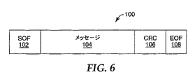
RFリーダー20およびRFタグは、所定フォーマットの1個以上のフレーム内に各々のメッセージが埋め込まれている公知のプロトコルを用いて通信する。例証的RFID送信フレーム100のフォーマットを図6に示す。フレーム100は、フレーム開始(SOF)102、メッセージ104、巡回冗長検査(CRC)106、およびファイル終了(EOF)108を含んでいる。SOF102は、フレームの開始を示す。同様に、EOF108はフレーム全体が送信されたことを示す。任意の非固定されたデータがフレーム100のメッセージ104部分に埋め込められていて、CRC106はメッセージ104内のデータを反映する。
The
CRC106を用いてデータの完全性を検査する。CRC106を計算するために、データの全てのビットが所定のアルゴリズムの処理を受ける。フレームが送信されたならば、受信器は受信データを用いてCRC106を復号化し、メッセージ104が適切に送信されたか否かを判定する。受信データから生成されたCRCが、フレーム自身の内部に含まれるCRCと合致しないとき、エラーが発生する。
ここに記載している技術の一態様は、チェックアウトされていない(すなわち依然としてチェックイン状態の)タグだけが検問通路を通過する際に応答することを保証することを目的とする。これは、アプリケーション群識別子(AFI)バイトと呼ばれる特徴を利用して実現することができる。この特徴について、RFIDシステムのISO15693標準に記載されている。AFIバイトは、8ビット値を含むRFIDタグ内のメモリの一部である。AFIは通常、書籍、CD、ビデオテープ等、タグが取り付けられた物品の種類を識別するために用いる。AFI位置に格納された値は、ISO15693標準に記載されている一連の規定されたコマンドにより変更することができる。RFリーダーがAFIコマンドを発行したとき、AFI値を送信する。ISO15693標準に規定されているように、コマンドに含めて送信されたAFI値が0x00(16進表示)であるとき、検問域内の全てのタグが応答する。RFリーダーが0x00以外の任意の値を送信したとき、合致するAFI値をメモリ内に有するタグだけがコマンドに応答する。 One aspect of the technology described herein is aimed at ensuring that only unchecked (ie, still checked-in) tags respond as they pass through the interrogation path. This can be achieved using a feature called application group identifier (AFI) bytes. This feature is described in the ISO 15693 standard for RFID systems. The AFI byte is the portion of memory in the RFID tag that contains an 8-bit value. AFI is typically used to identify the type of article to which a tag is attached, such as a book, CD, video tape or the like. The value stored at the AFI location can be changed by a series of defined commands described in the ISO 15693 standard. When the RF reader issues an AFI command, the AFI value is transmitted. As specified in the ISO 15693 standard, when the AFI value transmitted in the command is 0x00 (hexadecimal display), all tags in the check area respond. When the RF reader sends any value other than 0x00, only tags that have matching AFI values in memory respond to the command.
本明細書に記載する技術はAFIバイトを用いて、物品のステータス、例えば物品がチェックアウト状態にあるか否かを示す。従って、AFI域をチェックイン状態/チェックアウト状態のステータスバイトとして用いる。書籍その他の物品が棚の上にある場合、AFIバイトは指定された「チェックイン状態」値に設定される。司書が書籍をチェックアウトしたか、または客が自己チェックステーションでチェックアウトしたとき、AFI値は異なる「チェックアウト状態」値に変更される。 The techniques described herein use AFI bytes to indicate the status of an article, for example, whether the article is in a checked out state. Therefore, the AFI area is used as a check-in / check-out status byte. If a book or other item is on the shelf, the AFI byte is set to the specified “check-in state” value. When a librarian checks out a book or a customer checks out at a self-check station, the AFI value is changed to a different “checkout state” value.
RFリーダーは、チェックイン状態値をAFIメモリ位置に含んでいるタグをスキャンする。これにより、AFIバイトが「チェックイン状態」に設定されている全てのタグに応答させる。RFリーダーがタグから応答を受信したとき、当該物品は適切にチェックアウトされていない。この理由は、適切にチェックアウトされた物品は全て自身のAFIバイトにチェックイン状態値を有しておらず、従って応答しないからである。 The RF reader scans for tags that contain a check-in status value in an AFI memory location. As a result, all tags whose AFI byte is set to the “check-in state” are made to respond. When the RF reader receives a response from the tag, the item is not properly checked out. This is because all properly checked out articles do not have a check-in status value in their AFI byte and therefore do not respond.
AFIバイトをチェックイン状態/チェックアウト状態のステータスバイトとして使用する技術の例について以下に述べる。客が、自動図書返却口へ物品を返却する。図書返却口は、連続番号を読み、AFIバイトを「チェックイン状態」に設定する。物品が棚に戻され、次いで他の客が物品を持って退出しようとする。新しい客は、うっかり図書のチェックアウトを行なわずに退出する。当該客は呼掛け通路を歩くが、そこでは「チェックイン状態」値を有するタグを探索している。システムが通路内にチェックイン状態タグを発見したら、システムは警報を起動する。 An example of a technique that uses the AFI byte as the status byte in the check-in / check-out state is described below. The customer returns the item to the automatic book return port. The book return port reads the serial number and sets the AFI byte to “check-in state”. The article is returned to the shelf and then another customer tries to leave with the article. New customers leave without checking out the books inadvertently. The customer walks through the interrogation passage where he is searching for a tag having a “checked in” value. If the system finds a check-in status tag in the aisle, the system will trigger an alarm.
逆に、客が物品を適切にチェックアウトした場合、AFIバイトは「チェックアウト状態」に設定される。客が通路を通る際に、システムはチェックイン状態タグにしか応答を求めないため、タグはシステムのコマンドに応答しない。このように、客は通路を歩くことができ、警戒を鳴らすことなく物品を持ち出すことができる。 Conversely, when the customer properly checks out the item, the AFI byte is set to the “checked out state”. The tag does not respond to system commands because the system only asks for a check-in status tag as the customer passes through the aisle. In this way, the customer can walk along the aisle and take out the goods without sounding alert.
本明細書に記載する第二の技術は、受信したタグとの通信内容が実際にタグが生成した応答であって、ノイズにより生成されたものではないことを検証することを目的とする。すなわち、一実施形態において、システムは検問フィールド内にある全てのタグに同時に応答するよう求める。通常の状況下において、検問フィールド内に一度に1個のタグが存在する状況でしかこれは行なわれない。同一タイムスロットに2個以上のタグが応答した場合に、「衝突」と呼ばれる状況が生じる。通常、衝突が生じたとき、応答するタグのメッセージ104を適切に受信することができない。多くのシステムにおいて、衝突防止と呼ばれる方法が実装されていて、全てのタグが識別されるまで、タグは異なるタイムスロットに応答するよう指示される。しかし、このプロセスは往々にして、タグが素早く通路を通り抜ける出口制御アプリケーションで多くの時間を消費する。
The second technique described in the present specification aims to verify that the communication content with the received tag is a response actually generated by the tag and not generated by noise. That is, in one embodiment, the system asks to respond to all tags in the query field at the same time. Under normal circumstances, this is done only in situations where there is one tag at a time in the check field. A situation called “collision” occurs when two or more tags respond to the same time slot. Normally, when a collision occurs, the
これに対して、本明細書に記載する技術は、衝突が起きるのは複数の未チェックアウト(チェックイン状態)タグが通路内に存在する場合であるとの知識に基づき、全てのタグに、同一タイムスロット内に応答するよう求める。本実施形態は、衝突が起きた場合でもSOFが依然として正常に受信可能な一つの情報である事実を利用する。SOFとは、コマンドに応答してタグから送られた最初の送信である。何個のタグがコマンドに応答するかに関わらず、これらは全て同時に同一SOFを以って応答する。SOFを検知することにより、システムは少なくとも1個のチェックイン状態タグが実際に検問フィールド内に存在することを検証する。 On the other hand, the technique described in the present specification is based on the knowledge that a plurality of unchecked (checked-in) tags exist in the passage based on the knowledge that a collision occurs in all tags. Ask to respond within the same time slot. This embodiment uses the fact that even if a collision occurs, the SOF is still one information that can be normally received. SOF is the first transmission sent from a tag in response to a command. Regardless of how many tags respond to the command, they all respond at the same time with the same SOF. By detecting the SOF, the system verifies that at least one check-in status tag is actually present in the query field.
図7に、2個のタグ信号、すなわち第一のタグ信号110および第二のタグ信号112の例を示す。信号110および112は共に同一SOFを送信するが、メッセージフィールドには異なるデータを有する。両方のタグが同時に応答し、且つデータがRFリーダーへ帰還する分配器/結合器で結合されるため、RFリーダーが受信したメッセージフィールドのデータは衝突する恐れがある。しかし、SOFは、検問フィールド内に何個のタグが存在しようと衝突しない。
FIG. 7 shows an example of two tag signals, that is, a
図8は、ステータスバイトとしてAFIバイトを、および未チェックタグが検問フィールド内に存在することの確証としてSOFを用いて、検問通路における未チェックタグの存在を検証する本技術のフロー図130である。最初に、RFリーダーは、AFI値がチェックイン状態に設定されているAFIコマンドを送信する(134)。合致するチェックイン状態AFIバイトを有する各タグが応答し、チェックイン状態タグ応答であり得る内容が受信される(136)。次に、当該応答が実際のタグ応答であって、ノイズにより生成されたものではないことを検証すべく、システムはSOFを検査する(138)。正常なSOFを受信した場合、少なくとも1個のチェックイン状態タグが検問通路内に存在し(140)、警報が出される(142)。警報は、所定の持続期間にわたり出される。一方、有効なSOFを受信しなかった場合、システムはノイズにより応答が生じたものであり、従って通路内にチェックイン状態タグが存在しない(146)と見なす。ループは次いで、AFIコマンドを送信(134)することにより再開する。 FIG. 8 is a flow diagram 130 of the present technology for verifying the presence of an unchecked tag in an inspection path using an AFI byte as a status byte and SOF as confirmation that an unchecked tag is present in the inspection field. . First, the RF reader transmits an AFI command in which the AFI value is set to the check-in state (134). Each tag that has a matching check-in status AFI byte responds, and content that can be a check-in status tag response is received (136). Next, the system checks the SOF to verify that the response is an actual tag response and not generated by noise (138). If a normal SOF is received, at least one check-in status tag is present in the interrogation path (140) and an alarm is issued (142). The alarm is issued for a predetermined duration. On the other hand, if a valid SOF is not received, the system assumes that there was a response due to noise and therefore there is no check-in status tag in the path (146). The loop then resumes by sending (134) an AFI command.
他の実施形態において、SOFの有効性を確実にする技術が用いられている。特に、受信信号の強度インジケータを用いて、実際にタグが生成した応答をノイズが生成した応答から分離する。図9に、ノイズが存在する場合のタグ信号フレームの例を示す。タグ信号114は、ノイズフロア120上に示される。このノイズフロアは、後述するように、測定され、かつ有効なSOFを検証するために解析される。
In other embodiments, techniques are used to ensure the effectiveness of the SOF. In particular, the received signal strength indicator is used to separate the response actually generated by the tag from the response generated by the noise. FIG. 9 shows an example of a tag signal frame in the presence of noise.
図10は、本技術を示すフロー図170である。図10は、AFIバイトをチェックイン状態/チェックアウト状態のステータスバイトとして利用し、タグが生成した信号を確認するためにSOFを用いる点で図8に類似している。また、図10のフロー図は受信信号強度技術を用いてSOFを確認する。最初に、AFIバイトがチェックイン状態(166)に設定された状態でAFIコマンドが送られる。次いで、タグ応答が来る前に通路のノイズフロアが測定される(164)。AFIバイトがチェックイン状態に設定されたタグはいずれもコマンドに応答し、この応答が受信されて信号強度が測定される(168)。システムは次に、SOFを検査する(170)。SOFが検知されたとき、応答信号強度がノイズフロア(172)と比較される。この理由は、SOFを受信したことは検問フィールド内にタグが存在するとの徴候ではあるが、SOFは長さが8ビットに過ぎないため、時折ノイズがSOFシーケンスを生成する恐れがあるからである。応答信号強度とノイズフロアとの差が、信号が真正である(174)ことを示すのに充分であるとき、システムは検問フィールド内にチェックイン状態タグが存在することを確認する(176)。システムは次いで、警報を発信する(178)。一方、差が充分でない(174)とき、システムはノイズが応答を生成したものであり、従って、通路内にチェックイン状態タグが存在しないと見なす(182)。次いで、上記ループは再開される。 FIG. 10 is a flow diagram 170 illustrating the present technology. FIG. 10 is similar to FIG. 8 in that the AFI byte is used as the status byte in the check-in / check-out state and SOF is used to confirm the signal generated by the tag. Also, the flowchart of FIG. 10 confirms the SOF using the received signal strength technique. First, an AFI command is sent with the AFI byte set to the check-in state (166). The aisle noise floor is then measured (164) before the tag response comes. Any tag with the AFI byte set to the checked-in state responds to the command, and the response is received and the signal strength is measured (168). The system then examines the SOF (170). When SOF is detected, the response signal strength is compared with the noise floor (172). This is because receiving SOF is a sign that there is a tag in the query field, but since SOF is only 8 bits long, noise can occasionally generate SOF sequences. . When the difference between the response signal strength and the noise floor is sufficient to indicate that the signal is authentic (174), the system verifies that a check-in status tag is present in the interrogation field (176). The system then issues an alarm (178). On the other hand, if the difference is not sufficient (174), the system assumes that the noise has generated a response, and therefore there is no check-in status tag in the path (182). The loop is then resumed.
図11A、11Bは、受信されたタグ応答の可能性があるものとノイズフロア(図10の172)を比較する方法の二つの実施形態を示す。図11Aにおいて、方法172Aは最初に、測定されたノイズフロアと測定された信号強度の差異を求めるが、ここに、信号強度測定は、受信信号が真正(202)であることを示すのに充分な信号応答期間内に行なわれる。信号強度の差異が、信号が真正(204)であることを示すのに充分である場合、RFリーダーは未チェックアウト(すなわちチェックイン状態)タグが通路内に存在することを示唆する(208)。信号強度差が、受信信号が真正であることを示すのに充分でない場合、RFリーダーはノイズが応答を生成し、従って通路内にチェックイン状態タグが存在しないと見なす(206)。
FIGS. 11A and 11B show two embodiments of a method for comparing the possible tag response received and the noise floor (172 in FIG. 10). In FIG. 11A,
図11Bにおいて、本方法はSOFの前だけでなく、予想されるタグ応答が終了した後でもノイズフロアに着目する。EOFを受信した後でノイズフロアを確認することは、当該応答が実際にタグが生成した応答であって、ノイズが生成した応答ではないことの更に別の確認である。方法172Bは最初に、SOFの前に測定されたノイズフロアと信号強度との差異を求める(220)。この差異が、信号が真正(222)であることを示すには充分でない場合、本システムは、これはノイズが生成した応答および信号であって、通路内にチェックイン状態タグ存在しないものと仮定する(226)。差異が充分である場合(222)、システムは次に、予想されるタグ応答のEOFの後で測定された信号強度とノイズフロアの差異を求める(228)。この差異もまた充分(230)である場合、システムは通路内にチェックイン状態タグが存在することを通知する(232)。
In FIG. 11B, the method focuses on the noise floor not only before the SOF but also after the expected tag response has ended. Confirming the noise floor after receiving the EOF is yet another confirmation that the response is actually a response generated by the tag and not a response generated by noise.
図10、11に示す技術はいくつかの利点をもたらす。全てのタグを同一タイムスロット内で応答させることにより、検問フィールド内にチェックイン状態タグが存在するか否かを判定するために要する時間が大幅に短縮される。最短走査時間が約60msから約20msへ短縮される。また、全てのチェックイン状態タグが同時に応答した場合、RF受信器へ帰還する信号が結合されるため、チェックイン状態タグを検知する可能性が増大する。また、システムはSOFだけを探すため、チェックイン状態しているか否かを判定するために全でのタグ送信を受信する必要はない。これが起こり得るのは、タグが検問フィールドのより弱い部位へ移動して、送信の途中でエネルギーが失われた場合である。このようにして、タグが自身の連続番号の一部を送信するのに充分なエネルギーしか有しない場合であっても、システムは確実に警報を出力することができる。実際、チェックイン状態タグは、その存在をシステムが検知するために、自身そのSOFを送信するだけで済む。さらに、複数のタグが同時に応答した場合でもシステムに障害が起きない。事実、本システムはこのようなケースを想定して設計されている。同時に生起する複数のタグ応答により、実際にチェックイン状態タグが検知される可能性が高まる。 The techniques shown in FIGS. 10 and 11 provide several advantages. By making all tags respond within the same time slot, the time required to determine whether there is a check-in status tag in the check field is greatly reduced. The shortest scanning time is reduced from about 60 ms to about 20 ms. Also, if all the check-in status tags respond simultaneously, the signal returning to the RF receiver is combined, increasing the possibility of detecting the check-in status tag. Also, since the system looks for only SOF, it is not necessary to receive all tag transmissions to determine if it is in a check-in state. This can happen when the tag moves to a weaker part of the interrogation field and energy is lost during transmission. In this way, the system can reliably output an alarm even if the tag has enough energy to transmit a portion of its sequence number. In fact, the check-in status tag only needs to send its SOF itself in order for the system to detect its presence. Furthermore, even if a plurality of tags respond simultaneously, the system does not fail. In fact, the system is designed for such cases. A plurality of tag responses that occur at the same time increases the likelihood that a checked-in tag is actually detected.
信号強度インジケータは、各種の実施形態を利用して実装することができる。一実施形態において、信号強度インジケータは、回路により実現され、受信信号強度の徴候を与える。この情報は、増幅されてコントローラ(図2の参照番号14)へ送られる。コントローラ14はアナログ/デジタル変換器を用いて、図11A、11Bを参照しつつ上述のように信号を解析する。
The signal strength indicator can be implemented using various embodiments. In one embodiment, the signal strength indicator is implemented by a circuit and provides an indication of received signal strength. This information is amplified and sent to the controller (
図12に、検問通路内にチェックイン状態タグが存在するか否かをRFリーダーが判定できる方法の別の実施形態を示す。本プロセス(250)は、上記で述べたテキサス・インスツルメンツ社から販売されている「Tag−it」タイプのタグが使用される。Tag−itプロトコルには、検問フィールド内の全てのタグが規定されたブロックに格納されたデータを以って応答し、且つそれらが全て同時に応答するコマンドがある。本技術は、タグ内のデータの1ブロックを「チェックアウト・ステータスブロック」として設定する。このコマンドは次いで、少なくとも1個の未チェックアウト(チェックイン状態)タグが検問フィールド内に存在するか否かを判定するために用いる。 FIG. 12 illustrates another embodiment of a method by which an RF reader can determine whether a check-in status tag is present in an inspection passage. This process (250) uses a tag of the “Tag-it” type sold by Texas Instruments, Inc. as described above. In the Tag-it protocol, there is a command in which all tags in the inquiry field respond with data stored in a specified block, and they all respond simultaneously. The present technology sets one block of data in the tag as a “checkout / status block”. This command is then used to determine whether at least one unchecked out (checked in) tag is present in the query field.
例えば、チェックアウト状態の書籍のチェックアウト・ステータスブロックが、
00000001
に設定されると、チェックイン状態の書籍のデータは、
00000000
に設定される。
For example, a checkout / status block for a book that is in the
00000001
If set to, data for checked-in books is
00000000
Set to
タグが検問フィールド内を移動するにつれて、「無アドレスブロック読み取り」コマンドがRFリーダーにより送られる。検問フィールド内の全てのタグが同時に応答する。タグが応答するに従い、RFリーダーは上記のようにSOFを受信する。各々のタグのチェックアウト・ステータスブロックは、チェックアウト状態タグとチェックイン状態タグの両方が存在するとき、最終ビットおよびCRCを除いて同一である。本方法は、チェックアウト・ステータスブロックおよびCRCの最終ビットに衝突があるかを調べて、検問フィールド内に少なくとも1個のチェックイン状態タグが存在するか否かを判定する。例えば、以下の表は起こり得る可能性を示し、ここに「クリア」は衝突が検知されなかったことを示す。 As the tag moves through the query field, a “read no address block” command is sent by the RF reader. All tags in the check field respond at the same time. As the tag responds, the RF reader receives the SOF as described above. The checkout status block for each tag is identical except for the last bit and CRC when both a checkout status tag and a checkin status tag are present. The method checks if there is a collision in the checkout status block and the last bit of the CRC to determine if there is at least one check-in status tag in the query field. For example, the following table shows the possibilities, where “clear” indicates that no collision was detected.

図12を参照するに、RFリーダーは、「無アドレスブロック読み取り」コマンド(252)を送る。タグ応答であり得る内容が受信される(254)。システムは、図8、図10及び/又は図11に関する上記の技術を用いてSOFについて検査する。SOFが検知されなかった(256)場合、リーダーは検査を続ける(252)。SOFが検知された場合、システムはチェックアウト・ステータスバイト(258)の最後のビットにおける衝突の有無を検査する。衝突が検知された(260)とき、リーダーは次にCRCを検査する(262)。CRCにおいて衝突が検知されたとき、システムは、通路内に当該少なくとも1個のチェックイン状態タグが存在する(264)ことを通知して、警報を起動する(266)。これは、上記の表の第3行に示す状況である。 Referring to FIG. 12, the RF reader sends a “read no address block” command (252). Content that may be a tag response is received (254). The system tests for SOF using the techniques described above with respect to FIG. 8, FIG. 10 and / or FIG. If no SOF is detected (256), the reader continues with the test (252). If SOF is detected, the system checks for a collision in the last bit of the checkout status byte (258). When a collision is detected (260), the reader next checks the CRC (262). When a collision is detected in the CRC, the system notifies the presence of the at least one checked-in tag in the aisle (264) and activates an alarm (266). This is the situation shown in the third row of the above table.
チェックアウト・ステータスビットにおいて衝突が起きなかった(260)とき、リーダーはチェックアウト・ステータスビットがチェックイン状態に設定されているか否かを判定する(268)。設定されているとき、リーダーはCRCにおける衝突について検査する(270)。衝突が起きていないとき、通路内の全てのタグはチェックイン状態タグ(272)であり、コントローラは警報を出力する(266)。これは、上記の表の第2行に示す状況である。 When no collision has occurred in the checkout status bit (260), the reader determines whether the checkout status bit is set to the checked-in state (268). When set, the reader checks for collisions in the CRC (270). When no collision has occurred, all tags in the passage are checked-in tags (272) and the controller outputs an alarm (266). This is the situation shown in the second row of the above table.
チェックアウト・ステータスビット(260)において衝突が起きず、チェックアウト・ステータスビットがチェックインされていないとき、当該書籍はチェックアウト状態でなければならず、通路内にチェックイン状態タグが存在せず(274)、次の応答が調べられる(276)。これは、上記の表の第1行に示す状況である。 When there is no collision at the checkout status bit (260) and the checkout status bit is not checked in, the book must be in a checked out state and there is no checked in status tag in the passage. (274) The next response is examined (276). This is the situation shown in the first row of the above table.
他の実施形態を用いても、検問通路におけるチェックイン状態タグの存在を判定することができる。これらの実施形態の一つを図13に示す。本フロー図は、RFリーダー内で連続的に動作するアルゴリズムを表わすことができる。RFリーダーが警報(320)を指示したとき、チェックイン状態の書籍が検問通路を通過したことを通知するメッセージが、コントローラへ送られる。図13に示すこのアルゴリズムは、タグを最初に走査する間、衝突およびエネルギーが過剰なタグを無視する。本アルゴリズムは、可能な限り迅速かつ可能な限り多くのタグを読むことに集中する。 Other embodiments can also be used to determine the presence of a check-in status tag in an inspection passage. One of these embodiments is shown in FIG. The flow diagram can represent an algorithm that operates continuously within an RF reader. When the RF reader issues an alarm (320), a message is sent to the controller notifying that the checked-in book has passed the check passage. The algorithm shown in FIG. 13 ignores collisions and over-energy tags during the initial scanning of the tags. The algorithm focuses on reading as many tags as possible and as quickly as possible.
図13に示すアルゴリズムにより、大幅に性能が低下することなく現行のTI社製の「Tag−it」およびTI社製のISO15693−3タグを出口制御システムに用いることができる。TI社製のタイプのタグがチェックイン状態であるか否かを判定する一つの従来方式として、検問フィールド内の全てのタグに対してSID(同時識別)ポーリング実行し、次いでチェックイン状態/チェックアウト状態のコードが保存されている特定のブロックから読み出すことである。この技術における一つの潜在的な課題は、全ての衝突が解決される(複数のタグが同時に通信する場合)まで、SIDポーリングが継続し続ける点であり、また、本アルゴリズム実行中に1個のタグが検問フィールドから離れたとき、プロセスは停止し、データが戻らないことである。これは、客が(タグを備えた)書籍を抱えて出口制御システムを歩いて通過する場合のように、タグが常に検問フィールドに出入りする検知環境において極めて容易に起こり得る。 With the algorithm shown in FIG. 13, the current “Tag-it” manufactured by TI and ISO 15693-3 tag manufactured by TI can be used in the exit control system without significantly degrading performance. As one conventional method for determining whether or not a TI type tag is in a check-in state, SID (simultaneous identification) polling is executed for all tags in the check field, and then a check-in state / check It is to read out from a specific block in which the code in the out state is stored. One potential problem with this technology is that SID polling continues until all collisions are resolved (when multiple tags communicate simultaneously), and one When the tag leaves the query field, the process stops and no data is returned. This can happen very easily in a detection environment where the tag always enters and exits the interrogation field, such as when a customer carries a book (with a tag) and walks through the exit control system.
図13に示すアルゴリズムは、修正されたSIDポーリング(302)を用いて、アルゴリズム(304および310)を通じて、可能な限り第1回に迅速且つ可能な限り多くのタグを解決しよう試みるものである。チェックイン状態コードが設定されたタグが見つかった(312)とき、警報が起動される(320)。まだ時間が残っている(304)(タグが依然として検問フィールドに存在する)とき、本アルゴリズムは可能な限り多くの衝突を解決しようとする(308)。解決に充分な時間がないとき、マスク化されていないSIDポーリングを発行するだけで、衝突を無視するため、本アルゴリズムが検問フィールド内における未チェックアウトタグを識別できる速度が向上する。 The algorithm shown in FIG. 13 attempts to resolve as many tags as quickly and as much as possible through the algorithms (304 and 310) using the modified SID polling (302). When a tag with a check-in status code is found (312), an alarm is activated (320). When time remains (304) (the tag is still in the query field), the algorithm tries to resolve as many conflicts as possible (308). When there is not enough time to resolve, simply issuing an unmasked SID poll and ignoring the collision increases the speed at which the algorithm can identify unchecked out tags in the query field.
本方法の統計値を以下に記載する。括弧内に与える第一の数の組は、SIDコードで最下位桁の例である。これは、16タイムスロットのSIDアルゴリズムに基づいている。括弧内の第二の数の組は、第一パスの後で確認されたタグの個数である。
タグ0個 100.00%
タグ1個 100.00%
タグ2個:15/16の読み取り確率 93.75%
タグ3個:衝突無し(012)210/256の確率(82.03%)
衝突1回(011)45/256の確率(17.57%)
衝突2回(111)1/256の確率(0.39%)
全体確率:
衝突無し+1/3×衝突1回+0×衝突2回 87.89%
タグ4個:衝突無し(0123)2730/4096の確率(66.65%)
衝突1回(0012)1260/4096の確率(30.76%)
衝突2回(0001)60/4096の確率(1.46%)
二重衝突(0011)45/4096の確率(1.10%)
衝突3回(0000)1/4096の確率(0.02%)
全体確率:
衝突無し+1/2×1回+1/4×2回+0×二重+0×3回 82.31%
タグ5個:衝突無し(01234)32760/65536(49.99%)
衝突1回(00123)27300/65536(41.66%)
衝突2回(00012)2145/65536(3.27%)
衝突3回(00001)1290/65536(1.97%)
衝突4回(00000)1/65536(0.00%)
2回/2回(00122)1890/65536(2.88%)
2回/3回(00111)150/65536(0.22%)
全体確率:
衝突無し+3/5×1回+2/5×2回+1/5×3回+1/5×(2回/2回) 77.26%
The statistics of this method are listed below. The first set of numbers given in parentheses is an example of the least significant digit in the SID code. This is based on a 16 time slot SID algorithm. The second set of numbers in parentheses is the number of tags identified after the first pass.
0 tags 100.00%
One tag 100.00%
2 tags: 15/16 read probability 93.75%
3 tags: No collision (012) 210/256 probability (82.03%)
1 collision (011) 45/256 probability (17.57%)
Probability of collision (111) 1/256 (0.39%)
Overall probability:
No collision + 1/3 x 1 collision + 0 x 2 collisions 87.89%
4 tags: No collision (0123) 2730/4096 probability (66.65%)
1 collision (0012) 1260/4096 probability (30.76%)
2 collisions (0001) probability of 60/4096 (1.46%)
Double collision (0011) 45/4096 probability (1.10%)
3 collisions (0000) 1/4096 probability (0.02%)
Overall probability:
No collision +1/2 x 1 time + 1/4 x 2 times + 0 x double + 0 x 3 times 82.31%
5 tags: No collision (01234) 32760/65536 (49.99%)
One collision (00123) 27300/65536 (41.66%)
2 collisions (00012) 2145/65536 (3.27%)
3 collisions (00001) 1290/65536 (1.97%)
4 collisions (00000) 1/65536 (0.00%)
Twice / 2 times (00122) 1890/65536 (2.88%)
2/3 times (00111) 150/65536 (0.22%)
Overall probability:
No collision + 3/5 x 1 + 2/5 x 2 + 1/5 x 3 + 1/5 x (2/2) 77.26%
3個のタグの場合、衝突がなければ、全てのタグが確認される点に注意されたい。1回の衝突がある場合、衝突しているタグは読まれない、しかし、合致しない1個のタグが読まれ、これが3個の可能なタグのうちの1個であるため、分数1/3を用いて、1回衝突に遭う百分率の確率に乗算する。この論理を、他のタグが4および5個ある場合の統計値全体にわたり続ける。また、これらの百分率が第一パスについてのみであり、他のタグは、時間とタグの位置が許すならば、後続のパスで解決されることを理解されたい。 Note that in the case of three tags, all tags are confirmed if there is no collision. If there is a single collision, the colliding tag is not read, but the one tag that does not match is read and this is one of three possible tags, so the fraction 1/3 Is used to multiply the percentage probability of encountering a single collision. This logic continues throughout the statistics when there are 4 and 5 other tags. It should also be understood that these percentages are for the first pass only, and that other tags are resolved in subsequent passes if time and tag location allow.
チェックイン状態タグ検知の別の実施形態を図14に示す。本アルゴリズムは、適切にチェックアウトされた物品のタグIDを含んでいるデータベースを参照する。このデータベースは出口制御システム内に存在してもよいが、本発明はこの方式に限定されない。 Another embodiment of check-in status tag detection is shown in FIG. The algorithm refers to a database containing the tag IDs of properly checked out items. This database may exist in the exit control system, but the invention is not limited to this scheme.
最初に、検問通路内のタグに対してSIFポーリングを実行する(352)。検問フィールド内でタグが検知された場合(354)、本アルゴリズムは、タグが検問通路から出る前に解決可能なタグIDだけを集める(360)。タグが検問通路から出るまでの時間の長さは、入口を通過する予想速度に基づく平均計算値、あるいは集められているタグの枚数により動的に決定することができる。 First, SIF polling is executed for the tag in the inspection passage (352). If a tag is detected in the interrogation field (354), the algorithm collects only resolvable tag IDs before the tag exits the interrogation path (360). The length of time it takes for a tag to leave the interrogation path can be dynamically determined by an average calculation based on the expected speed of passing through the entrance, or the number of tags collected.
各々の衝突が解決された後で、タグの追加的なポーリングを求めることもできる。このポーリングにより、最初のポーリングで得られたものと同じ重複タグIDが少なくとも1個得られなければ、新たな組のタグが検問通路内に入ったものと判定できる。これにより、タグの以前の組を求めるデータベース検索を生起させる。 It is also possible to ask for additional polling of tags after each collision is resolved. If at least one duplicate tag ID same as that obtained in the first polling is not obtained by this polling, it can be determined that a new set of tags has entered the inspection path. This causes a database search for the previous set of tags.
他の可能な方策としては、現在の衝突が解決できない場合は直ちにタグが通路から出たものと推測することがあげられる。これもまた、データベース検索を生起させる。 Another possible strategy is to immediately assume that the tag has left the passage if the current collision cannot be resolved. This also triggers a database search.
このように図14に示すアルゴリズムは特に、上記の時間が過ぎるまで、可能な限り多くのタグIDを集めて、セキュリティ情報について調べないことに注力する。その時点で、データベースに検索が実施されて、検知された全てのタグがセキュリティ・データベース内に存在するか否かを判定する。 In this way, the algorithm shown in FIG. 14 particularly focuses on collecting as many tag IDs as possible and not examining the security information until the above time has passed. At that point, a search is performed on the database to determine if all detected tags are present in the security database.
図14の実施形態がもたらす利点は、タグ検知に利用できる時間の長さと共に、不均一な電磁場の影響に関する。本アルゴリズムは、セキュリティ目的でサンプリングするタグの個数を最大化する手段を提供する。一旦タグIDが集められたならば、本システムはセキュリティ情報に関してタグと通信する必要がもはやないため、本アルゴリズムは不均一な電磁場があっても重大な影響を受けない。 The advantages provided by the embodiment of FIG. 14 relate to the effects of non-uniform electromagnetic fields, as well as the length of time available for tag detection. The algorithm provides a means to maximize the number of tags sampled for security purposes. Once the tag ID has been collected, the algorithm is no longer significantly affected by the presence of a non-uniform electromagnetic field because the system no longer needs to communicate with the tag for security information.
以下の議論は、新規な電子製品コード(EPC)で用いる方法に向けられている。EPCは、物品識別用にRFIDを用いることにより特定のアプリケーションにおける統一製品コード(UPC)に代わるべく設定されている。この新規な仕様の中に「破壊」コマンドがあり、これが実行された場合、RFIDタグを破壊するかまたは機能停止させる。本方法は、この破壊コマンド用にセキュリティ確保並びに検知が困難な「キー」を生成して、破壊コマンドを不正に使用してもRFIDタグの性能に影響を及ぼさないようにしている。 The following discussion is directed to a method for use with a new electronic product code (EPC). EPC is set to replace the Unified Product Code (UPC) in specific applications by using RFID for article identification. Within this new specification is a “destroy” command that, when executed, destroys or deactivates the RFID tag. This method generates a “key” that is difficult to ensure and detect security for the destruction command, and prevents the RFID tag performance from being affected even if the destruction command is used illegally.
破壊コマンドはRFIDタグを機能停止させる。破壊コードを設定するために、適切なコマンドをチップに与えてメモリをプログラムする。破壊コマンドを実行するために、破壊メモリ位置に置かれたパスワードを再びチップへ送信する必要があり、合致すればチップが破壊される。 The destroy command stops the RFID tag from functioning. To set the destruction code, the memory is programmed with the appropriate command given to the chip. In order to execute the destruction command, it is necessary to transmit the password placed at the destruction memory location to the chip again, and if it matches, the chip is destroyed.
本方法は、RFIDタグを破壊するためのセキュリティ保証された「キー」を生成する。あらゆる場所のあらゆるタグに1個のキーを用いた場合、何者かがキーを解読したならば、理論的にはその場所にある全てのRFIDを破壊することができる。例えば以下の通りである。 The method generates a secure “key” for destroying the RFID tag. If one key is used for every tag in every location, and if someone decrypts the key, theoretically, all RFIDs in that location can be destroyed. For example:
タグA タグB タグC
破壊コード:G G G
Tag A Tag B Tag C
Destruction code: G G G
破壊レジスタ内の同一コードにより、一箇所における全てのタグを危険にさらす恐れが生じる。 The same code in the destruction register creates a risk of putting all the tags in one place at risk.
しかし、本方法では、EPC識別コード(最大88ビットの情報)がアルゴリズムにより処理され、更に、破壊メモリ・レジスタ(24ビット)に置かれる。これにより、全ての破壊コマンドが各タグに対して一意となり、解読が困難な一意のキーが生成される。例えば以下の通りである。 However, in this method, the EPC identification code (up to 88 bits of information) is processed by the algorithm and further placed in the corrupted memory register (24 bits). As a result, all destruction commands are unique to each tag, and a unique key that is difficult to decipher is generated. For example:
タグA タグB タグC
破壊コード:U W L
Tag A Tag B Tag C
Destruction code: U W L
アルゴリズム「キー」は全てのタグおよび破壊コードに共通である。しかし、破壊コードをタグから読み込むことができないため、ここに記載する方法はアルゴリズムの解読をはるかに困難にし、従ってサイトの全体的なセキュリティが維持される。 The algorithm “key” is common to all tags and destruction codes. However, since the destructive code cannot be read from the tag, the method described here makes the algorithm much more difficult to decipher and thus maintains the overall security of the site.
EPC識別の例: 00000000 00 16進表示
11111111 FF
00000000 00
11111111 FF
00000000 00
11111111 FF
00000000 00
11111111 FF
00000000 00
11111111 FF
00000000 00
88ビットが、8ビットからなる11個のブロックに編成されている。
EPC identification example: 00000000 00 hexadecimal display
11111111 FF
00000000 00
11111111 FF
00000000 00
11111111 FF
00000000 00
11111111 FF
00000000 00
11111111 FF
00000000 00
88 bits are organized into 11 blocks of 8 bits.
アルゴリズムの例は、例えば、いくつかのメモリを選択して、関数(データまたは定数との加算、減算、乗算等)を実行し、出力破壊コマンドを生成することができる。 An example algorithm can, for example, select several memories and execute a function (addition, subtraction, multiplication, etc. with data or constants) to generate an output destruction command.
破壊コマンド 10001101 8D
(本例は無作為) 01111011 7B
00010110 16
Destruction command 10001101 8D
(This example is random) 01111011 7B
00010110 16
別のEPC値に本アルゴリズムを実行すれば、全く異なる破壊コマンド値が生成されよう。 If the algorithm is run on a different EPC value, a completely different destruction command value will be generated.
サイト間で、異なるアルゴリズムを用いて、異なるアルゴリズムによりタグが破壊されることが無いように、異なる店舗またはベンダーを識別することができる。出荷セキュリティの例において、ある小売業者へ販売された物品は、同一の小売業者しか販売することができない。異なるアルゴリズムを用いる2軒の店舗間で、同一のEPC値により異なる破壊コマンドコードが生成されるであろう。 Different sites can use different algorithms to identify different stores or vendors so that tags are not destroyed by different algorithms. In the shipping security example, an article sold to a retailer can only be sold by the same retailer. Different destruction command codes will be generated with the same EPC value between two stores using different algorithms.
本発明の各種の実施形態について記載してきた。これらおよび他の実施形態は、添付の請求項の範囲内にある。 Various embodiments of the invention have been described. These and other embodiments are within the scope of the appended claims.
Claims (2)
前記複数のアンテナに接続されたRFリーダーであって、前記検問通路内に検問フィールドを生成するために前記複数のアンテナの各々にRF電波を提供すると共に前記RFリーダーに結合入力信号を配信する単一の送受信器(T/R)ポートを有し、かつ前記検問通路内に少なくとも1個のタグが存在することを示すべくタグ検出信号を生成する、RFリーダーと、
前記RFリーダーからの前記RF電波を受信し、複数のアンテナ駆動信号の形で前記複数のアンテナの各々に前記RF電波を配信する分配器であって、前記複数のアンテナからの1個以上の信号を受信し、前記結合入力信号を形成するために前記1個以上のタグ信号を結合する、分配器と、
いずれかの前記検問通路において客を検出し、客信号を生成する複数のセンサと、
一定時間内に前記タグ検出信号および前記客信号を受信すると警報信号を出力するコントローラと、を含むシステム。A plurality of radio frequency (RF) antennas installed to provide one or more interrogation paths;
An RF reader connected to the plurality of antennas, which provides an RF radio wave to each of the plurality of antennas and generates a combined input signal to the RF reader in order to generate an inspection field in the inspection path. An RF reader having a transceiver (T / R) port and generating a tag detection signal to indicate that there is at least one tag in the interrogation path;
A distributor that receives the RF radio waves from the RF reader and distributes the RF radio waves to each of the plurality of antennas in the form of a plurality of antenna drive signals, wherein one or more signals from the plurality of antennas A distributor for combining the one or more tag signals to form the combined input signal;
A plurality of sensors for detecting a customer in any of the inspection passages and generating a customer signal;
A controller that outputs an alarm signal when receiving the tag detection signal and the customer signal within a predetermined time .
分配器を使用して、前記RF出力信号を複数のアンテナ駆動信号として分配するステップと、
1個以上の検問通路内において検問フィールドを生成するために、前記アンテナ駆動信号を複数のアンテナへ配信するステップと、
前記検問フィールド内に存在する少なくとも1個のタグに対応して、前記アンテナで1個以上の入力信号を発生するステップと、
前記分配器を使用して、前記入力信号を結合入力信号に結合させるステップと、
前記RFリーダーの前記T/Rポートに、前記結合入力信号を提供するステップと、
前記RFリーダーからの前記タグ検出信号をコントローラに出力するステップと、
いずれかの前記検問通路内に客が存在するか否かを示す客信号を受信するステップと、
一定時間内に前記タグ検出信号および前記客信号を受信すると警報信号を出力するステップと、を含む方法。Generating a radio frequency (RF) output signal from a single transceiver (T / R) port of the RF reader;
Distributing the RF output signal as a plurality of antenna drive signals using a distributor ;
Delivering the antenna drive signal to a plurality of antennas to generate an interrogation field in one or more interrogation paths;
Generating one or more input signals at the antenna corresponding to at least one tag present in the interrogation field;
Coupling the input signal to a combined input signal using the distributor;
Providing the combined input signal to the T / R port of the RF reader;
Outputting the tag detection signal from the RF reader to a controller;
Receiving a customer signal indicating whether a customer is present in any of the interrogation paths;
Outputting a warning signal when receiving the tag detection signal and the customer signal within a predetermined time .
Applications Claiming Priority (3)
| Application Number | Priority Date | Filing Date | Title |
|---|---|---|---|
| US10/705,677 | 2003-11-10 | ||
| US10/705,677 US7119692B2 (en) | 2003-11-10 | 2003-11-10 | System for detecting radio-frequency identification tags |
| PCT/US2004/034366 WO2005048211A2 (en) | 2003-11-10 | 2004-10-18 | System for detecting radio-frequency identification tags |
Publications (3)
| Publication Number | Publication Date |
|---|---|
| JP2007514215A JP2007514215A (en) | 2007-05-31 |
| JP2007514215A5 JP2007514215A5 (en) | 2007-12-06 |
| JP4723507B2 true JP4723507B2 (en) | 2011-07-13 |
Family
ID=34552421
Family Applications (1)
| Application Number | Title | Priority Date | Filing Date |
|---|---|---|---|
| JP2006539517A Expired - Fee Related JP4723507B2 (en) | 2003-11-10 | 2004-10-18 | RFID security algorithm |
Country Status (12)
| Country | Link |
|---|---|
| US (2) | US7119692B2 (en) |
| EP (2) | EP1852839B1 (en) |
| JP (1) | JP4723507B2 (en) |
| KR (1) | KR20060118474A (en) |
| AT (2) | ATE381752T1 (en) |
| AU (1) | AU2004289012B2 (en) |
| BR (1) | BRPI0416347A (en) |
| CA (1) | CA2545720A1 (en) |
| DE (2) | DE602004010838T2 (en) |
| HK (1) | HK1096188A1 (en) |
| TW (1) | TW200519759A (en) |
| WO (1) | WO2005048211A2 (en) |
Families Citing this family (54)
| Publication number | Priority date | Publication date | Assignee | Title |
|---|---|---|---|---|
| JP4019986B2 (en) * | 2003-03-20 | 2007-12-12 | セイコーエプソン株式会社 | Non-contact data communication system, position information management system, data communication apparatus, and data communication apparatus control program |
| US7372364B2 (en) * | 2003-11-10 | 2008-05-13 | 3M Innovative Properties Company | Algorithm for RFID security |
| US7119692B2 (en) * | 2003-11-10 | 2006-10-10 | 3M Innovative Properties Company | System for detecting radio-frequency identification tags |
| US7298264B1 (en) | 2004-01-20 | 2007-11-20 | Charles A. Eldering | RFID tag filtering and monitoring |
| US7420458B1 (en) | 2004-01-20 | 2008-09-02 | Charles A. Eldering | Secondary card reader |
| WO2005086072A1 (en) | 2004-03-03 | 2005-09-15 | Caducys, L.L.C. | Interrogator and interrogation system employing the same |
| ATE542186T1 (en) * | 2004-03-05 | 2012-02-15 | Seknion Inc | METHOD AND APPARATUS FOR IMPROVING THE PERFORMANCE AND ACCURACY OF RFID SYSTEMS |
| US20060173750A1 (en) * | 2004-12-30 | 2006-08-03 | Naley Martin R | System and method for controlling access to a local inventory storage system via a remote e-commerce application |
| DE102005018402B4 (en) * | 2005-04-20 | 2009-10-01 | Gea Westfaliasurge Gmbh | Diagnostic method and diagnostic device for an animal identification system, in particular an animal identification system of a milking installation and milking installation with an animal identification system |
| JP2006319710A (en) * | 2005-05-13 | 2006-11-24 | Brother Ind Ltd | Wireless tag communication system |
| US20070164865A1 (en) * | 2005-11-04 | 2007-07-19 | Gerald Giasson | Security sensor system |
| US7564354B2 (en) * | 2005-12-29 | 2009-07-21 | International Business Machines Corporation | Monitoring device for detecting opening of packaging |
| US7548165B2 (en) * | 2006-04-04 | 2009-06-16 | Pintey Bowes Inc. | Performance enhancement algorithm for radio frequency identification (RFID) systems |
| US7561044B2 (en) * | 2006-04-04 | 2009-07-14 | Pitney Bowes Inc. | Adaptive radio frequency identification control algorithm |
| US7663486B2 (en) * | 2006-06-16 | 2010-02-16 | Motorola, Inc. | RFID tag user memory indication |
| US20080065496A1 (en) * | 2006-08-29 | 2008-03-13 | Ncr Corporation | Methods and Apparatus for Managing RFID and Other Data |
| US8207826B2 (en) * | 2006-10-03 | 2012-06-26 | Ncr Corporation | Methods and apparatus for analyzing signal conditions affecting operation of an RFID communication device |
| KR100842958B1 (en) * | 2006-10-19 | 2008-07-01 | 한국정보통신대학교 산학협력단 | Query tree based tag identification method in rfid systems |
| KR100845666B1 (en) * | 2006-10-19 | 2008-07-10 | 한국정보통신대학교 산학협력단 | Bi-slotted tree based anti-collision protocols for fast tag identification in rfid systems |
| US20080120167A1 (en) * | 2006-11-17 | 2008-05-22 | Ac Technologies S.A. | Personal Inventory and Marketing Electronic System and Method |
| US7916022B2 (en) * | 2006-11-21 | 2011-03-29 | Deere & Company | Agricultural information gathering system |
| US20080204234A1 (en) * | 2007-02-28 | 2008-08-28 | Vijay Pillai | Systems and methods for increased memory capacity in a low-power environment |
| US20080278320A1 (en) * | 2007-05-07 | 2008-11-13 | Sensormatic Electronics Corporation | Method and system for reduction of electronic article surveillance system false alarms |
| CN101079111B (en) * | 2007-05-30 | 2010-08-11 | 上海复旦天臣新技术有限公司 | Intelligent rack and cargo monitoring method |
| US8330579B2 (en) | 2007-07-05 | 2012-12-11 | Baxter International Inc. | Radio-frequency auto-identification system for dialysis systems |
| KR101396430B1 (en) * | 2007-10-31 | 2014-05-20 | 삼성전자주식회사 | Apparatus and method for anti-collision tag in radio frequency identification system |
| NL2001161C2 (en) * | 2008-01-07 | 2009-01-27 | Nedap Nv | Articles e.g. library book, presence detecting system for library shelf, has scanning unit equipped in library shelf for detecting radio-frequency identification tags of library books, and write unit arranged at label |
| KR101204091B1 (en) * | 2008-01-23 | 2012-11-22 | 한양대학교 산학협력단 | RFID system preventing recognition error and communication method thereof |
| WO2009133527A2 (en) | 2008-04-30 | 2009-11-05 | Ecolab Inc. | Validated healthcare cleaning and sanitizing practices |
| US8639527B2 (en) | 2008-04-30 | 2014-01-28 | Ecolab Usa Inc. | Validated healthcare cleaning and sanitizing practices |
| JP5183501B2 (en) * | 2009-01-08 | 2013-04-17 | 三菱電機株式会社 | Determination apparatus, computer program, and determination method |
| PL2441063T3 (en) | 2009-06-12 | 2015-08-31 | Ecolab Usa Inc | Hand hygiene compliance monitoring |
| USRE48951E1 (en) | 2015-08-05 | 2022-03-01 | Ecolab Usa Inc. | Hand hygiene compliance monitoring |
| US8610574B2 (en) | 2009-06-15 | 2013-12-17 | Gerald Isaac Kestenbaum | Item storage and tracking system |
| US9007181B2 (en) * | 2010-01-08 | 2015-04-14 | Tyco Fire & Security Gmbh | Method and system for discovery and transparent status reporting for sensor networks |
| ES2381542B1 (en) * | 2010-02-04 | 2013-05-08 | Agotek Desarrollo Tecnologico, S.L. | SECURE PARKING SYSTEM FOR BICYCLES OR OTHER MOBILE OR TRANSPORTABLE OBJECTS BY THE HUMAN BEING |
| US8448072B1 (en) * | 2010-04-07 | 2013-05-21 | Sprint Communications Company L.P. | Interception of automatic status updates for a social networking system |
| DE102010054087A1 (en) * | 2010-12-10 | 2012-06-14 | Audi Ag | Method for wireless communication between a motor vehicle and at least one other communication subscriber and motor vehicle |
| US20140210620A1 (en) | 2013-01-25 | 2014-07-31 | Ultraclenz Llc | Wireless communication for dispenser beacons |
| DE102011005610A1 (en) * | 2011-03-16 | 2012-09-20 | Deutsche Post Ag | Method and system for monitoring objects |
| US8717165B2 (en) | 2011-03-22 | 2014-05-06 | Tassilo Gernandt | Apparatus and method for locating, tracking, controlling and recognizing tagged objects using RFID technology |
| US9311586B2 (en) | 2011-03-22 | 2016-04-12 | Jamie Robinette | Apparatus and method for locating, tracking, controlling and recognizing tagged objects using active RFID technology |
| US8536816B2 (en) | 2011-09-12 | 2013-09-17 | General Electric Company | Method and system for detecting faults in a brushless exciter |
| US8836197B2 (en) | 2012-03-23 | 2014-09-16 | General Electric Company | Brush holder having radio frequency identification (RFID)temperature monitoring system |
| EP2932477B1 (en) | 2012-12-12 | 2019-04-24 | Life Technologies Corporation | Self-locking door and product dispensing enclosure having a self-locking door |
| US10198604B2 (en) * | 2014-02-21 | 2019-02-05 | Sony Mobile Communications Inc. | Detection of unauthorized tags |
| WO2015174970A1 (en) * | 2014-05-13 | 2015-11-19 | Hewlett-Packard Development Company, L.P. | Wearable authentication |
| TWI650730B (en) * | 2014-07-21 | 2019-02-11 | 中國鋼鐵股份有限公司 | Carrier pallet mobile identification system |
| CA2965195A1 (en) | 2014-10-24 | 2016-04-28 | Life Technologies Corporation | Inventory management system and method of use |
| DK178276B1 (en) | 2014-12-19 | 2015-10-26 | Conpleks Innovation Aps | Method for recording and predicting position data for a selfpropelled wheeled vehicle, and delivery or pick up system comprising a self-propelled, self-guided wheeled vehicle |
| WO2018165107A1 (en) | 2017-03-07 | 2018-09-13 | Ecolab Usa Inc. | Monitoring modules for hand hygiene dispensers |
| JP6951912B2 (en) * | 2017-09-01 | 2021-10-20 | 東芝テック株式会社 | Reporting device |
| US10529219B2 (en) | 2017-11-10 | 2020-01-07 | Ecolab Usa Inc. | Hand hygiene compliance monitoring |
| EP3900307A1 (en) | 2018-12-20 | 2021-10-27 | Ecolab USA, Inc. | Adaptive route, bi-directional network communication |
Citations (4)
| Publication number | Priority date | Publication date | Assignee | Title |
|---|---|---|---|---|
| US4635041A (en) * | 1983-04-12 | 1987-01-06 | 2 M Security Systems Aps | Theft protection system particularly for shop areas |
| US4870391A (en) * | 1988-04-05 | 1989-09-26 | Knogo Corporation | Multiple frequency theft detection system |
| US5126749A (en) * | 1989-08-25 | 1992-06-30 | Kaltner George W | Individually fed multiloop antennas for electronic security systems |
| US6094173A (en) * | 1997-04-18 | 2000-07-25 | Motorola, Inc. | Method and apparatus for detecting an RFID tag signal |
Family Cites Families (44)
| Publication number | Priority date | Publication date | Assignee | Title |
|---|---|---|---|---|
| US4281321A (en) * | 1980-06-09 | 1981-07-28 | Sensormatic Electronics Corporation | Surveillance system employing a floor mat radiator |
| US4739328A (en) * | 1986-07-14 | 1988-04-19 | Amtech Corporation | System for identifying particular objects |
| US5103234A (en) * | 1987-08-28 | 1992-04-07 | Sensormatic Electronics Corporation | Electronic article surveillance system |
| FR2623311B1 (en) | 1987-11-18 | 1991-05-17 | Izadnegahdar Ali | IDENTIFICATION SYSTEM WITH CONTACTLESS QUERYING OF AN ELECTRONIC LABEL |
| US4864158A (en) * | 1988-01-28 | 1989-09-05 | Amtech Corporation | Rapid signal validity checking apparatus |
| US4888591A (en) * | 1988-10-06 | 1989-12-19 | Amtech Technology Corporation | Signal discrimination system |
| US5030941A (en) * | 1989-12-27 | 1991-07-09 | Checkpoint Systems, Inc. | Electronic article surveillance system incorporating an auxiliary sensor |
| US5055659A (en) * | 1990-02-06 | 1991-10-08 | Amtech Technology Corp. | High speed system for reading and writing data from and into remote tags |
| JPH0676185A (en) | 1990-12-26 | 1994-03-18 | W Karutoner George | Individual power-feeding multiplex loop antenna for electronic guard system |
| US5387900A (en) * | 1992-11-19 | 1995-02-07 | Sensormatic Electronics Corporation | EAS system with improved processing of antenna signals |
| US5353011A (en) * | 1993-01-04 | 1994-10-04 | Checkpoint Systems, Inc. | Electronic article security system with digital signal processing and increased detection range |
| NL9300124A (en) | 1993-01-22 | 1994-08-16 | Nedap Nv | Improved antenna configuration in supermarket shoplifting detection systems. |
| CN101398871B (en) | 1995-02-13 | 2011-05-18 | 英特特拉斯特技术公司 | Systems and methods for secure transaction management and electronic rights protection |
| DE19513203A1 (en) | 1995-04-11 | 1996-10-17 | Bayer Ag | Fumigation device for rotary kilns |
| CN1185865A (en) * | 1995-05-30 | 1998-06-24 | 传感电子公司 | EAS system antenna configuration for providing improved interrogation field distribution |
| US5929779A (en) | 1996-05-31 | 1999-07-27 | Lucent Technologies Inc. | Read/write protocol for radio frequency identification tags |
| JP3457816B2 (en) | 1996-11-27 | 2003-10-20 | 東芝テック株式会社 | Commodity sales data registration processing device having data rewriting function of non-contact communication type storage medium |
| US6104333A (en) * | 1996-12-19 | 2000-08-15 | Micron Technology, Inc. | Methods of processing wireless communication, methods of processing radio frequency communication, and related systems |
| US5841350A (en) | 1997-06-27 | 1998-11-24 | Checkpoint Systems, Inc. | Electronic security tag useful in electronic article indentification and surveillance system |
| US5926093A (en) * | 1997-08-15 | 1999-07-20 | Checkpoint Systems, Inc. | Drive circuit for reactive loads |
| US6037879A (en) * | 1997-10-02 | 2000-03-14 | Micron Technology, Inc. | Wireless identification device, RFID device, and method of manufacturing wireless identification device |
| US5909178A (en) | 1997-11-28 | 1999-06-01 | Sensormatic Electronics Corporation | Signal detection in high noise environments |
| US6487395B1 (en) * | 1998-03-16 | 2002-11-26 | Motorola, Inc. | Radio frequency electronic switch |
| US6388628B1 (en) | 1998-05-18 | 2002-05-14 | Db Tag, Inc. | Systems and methods for wirelessly projecting power using in-phase current loops |
| US6028518A (en) | 1998-06-04 | 2000-02-22 | Checkpoint Systems, Inc. | System for verifying attachment of an EAS marker to an article after tagging |
| EP1298573A3 (en) * | 1998-08-14 | 2003-09-17 | 3M Innovative Properties Company | Radio frequency identification system comprising a plurality of antennas |
| CN1158636C (en) | 1998-08-14 | 2004-07-21 | 3M创新有限公司 | Applications for radio frequency identification systems |
| US6069564A (en) * | 1998-09-08 | 2000-05-30 | Hatano; Richard | Multi-directional RFID antenna |
| US6307517B1 (en) | 2000-06-13 | 2001-10-23 | Applied Wireless Identifications Group, Inc. | Metal compensated radio frequency identification reader |
| US6696954B2 (en) * | 2000-10-16 | 2004-02-24 | Amerasia International Technology, Inc. | Antenna array for smart RFID tags |
| WO2002033511A2 (en) | 2000-10-16 | 2002-04-25 | Amerasia International Technology, Inc. | Article tracking system and method |
| US7253717B2 (en) | 2000-11-29 | 2007-08-07 | Mobile Technics Llc | Method and system for communicating with and tracking RFID transponders |
| US6396341B1 (en) * | 2000-12-29 | 2002-05-28 | Ericsson Inc. | Class E Doherty amplifier topology for high efficiency signal transmitters |
| US7100052B2 (en) | 2001-02-01 | 2006-08-29 | Loran Technologies, Inc. | Electronic vehicle product and personal monitoring |
| CA2437801C (en) | 2001-02-08 | 2010-06-01 | Sensormatic Electronics Corporation | Differentially coherent combining for electronic article surveillance systems |
| US20020180587A1 (en) | 2001-03-05 | 2002-12-05 | Datamars Sa | Method for communication with multiple transponders |
| AUPR850501A0 (en) * | 2001-10-29 | 2001-11-29 | Tagsys Australia Pty. Ltd. | Electronic label interrogation through incidental electromagnetic radiation |
| US6703935B1 (en) * | 2001-05-14 | 2004-03-09 | Amerasia International Technology, Inc. | Antenna arrangement for RFID smart tags |
| US7347379B2 (en) | 2001-11-02 | 2008-03-25 | Avid Identification Systems, Inc. | Dual antenna coil transponder system |
| US6816538B2 (en) | 2002-06-26 | 2004-11-09 | Elster Electricity, Llc | Frequency hopping spread spectrum decoder |
| JP3565217B2 (en) | 2002-10-29 | 2004-09-15 | オムロン株式会社 | Article management system, non-contact electronic tag, and article management program |
| US7333001B2 (en) | 2002-11-23 | 2008-02-19 | Kathleen Lane | Secure personal RFID documents and method of use |
| US7119692B2 (en) | 2003-11-10 | 2006-10-10 | 3M Innovative Properties Company | System for detecting radio-frequency identification tags |
| US7372364B2 (en) | 2003-11-10 | 2008-05-13 | 3M Innovative Properties Company | Algorithm for RFID security |
-
2003
- 2003-11-10 US US10/705,677 patent/US7119692B2/en not_active Expired - Fee Related
-
2004
- 2004-10-18 BR BRPI0416347-8A patent/BRPI0416347A/en not_active IP Right Cessation
- 2004-10-18 WO PCT/US2004/034366 patent/WO2005048211A2/en active IP Right Grant
- 2004-10-18 DE DE602004010838T patent/DE602004010838T2/en active Active
- 2004-10-18 KR KR1020067009094A patent/KR20060118474A/en active IP Right Grant
- 2004-10-18 AU AU2004289012A patent/AU2004289012B2/en not_active Ceased
- 2004-10-18 CA CA002545720A patent/CA2545720A1/en not_active Abandoned
- 2004-10-18 JP JP2006539517A patent/JP4723507B2/en not_active Expired - Fee Related
- 2004-10-18 DE DE602004025995T patent/DE602004025995D1/en active Active
- 2004-10-18 EP EP07113593A patent/EP1852839B1/en not_active Not-in-force
- 2004-10-18 EP EP04795513A patent/EP1683122B1/en not_active Not-in-force
- 2004-10-18 AT AT04795513T patent/ATE381752T1/en not_active IP Right Cessation
- 2004-10-18 AT AT07113593T patent/ATE460718T1/en not_active IP Right Cessation
- 2004-11-04 TW TW093133693A patent/TW200519759A/en unknown
-
2006
- 2006-10-09 US US11/539,716 patent/US7405663B2/en not_active Expired - Fee Related
- 2006-12-29 HK HK06114306A patent/HK1096188A1/en not_active IP Right Cessation
Patent Citations (4)
| Publication number | Priority date | Publication date | Assignee | Title |
|---|---|---|---|---|
| US4635041A (en) * | 1983-04-12 | 1987-01-06 | 2 M Security Systems Aps | Theft protection system particularly for shop areas |
| US4870391A (en) * | 1988-04-05 | 1989-09-26 | Knogo Corporation | Multiple frequency theft detection system |
| US5126749A (en) * | 1989-08-25 | 1992-06-30 | Kaltner George W | Individually fed multiloop antennas for electronic security systems |
| US6094173A (en) * | 1997-04-18 | 2000-07-25 | Motorola, Inc. | Method and apparatus for detecting an RFID tag signal |
Also Published As
| Publication number | Publication date |
|---|---|
| EP1683122B1 (en) | 2007-12-19 |
| US20050099302A1 (en) | 2005-05-12 |
| KR20060118474A (en) | 2006-11-23 |
| WO2005048211A3 (en) | 2005-09-15 |
| EP1683122A2 (en) | 2006-07-26 |
| DE602004010838D1 (en) | 2008-01-31 |
| CA2545720A1 (en) | 2005-05-26 |
| DE602004025995D1 (en) | 2010-04-22 |
| EP1852839A1 (en) | 2007-11-07 |
| WO2005048211A2 (en) | 2005-05-26 |
| AU2004289012A1 (en) | 2005-05-26 |
| JP2007514215A (en) | 2007-05-31 |
| EP1852839B1 (en) | 2010-03-10 |
| BRPI0416347A (en) | 2007-03-13 |
| US7119692B2 (en) | 2006-10-10 |
| TW200519759A (en) | 2005-06-16 |
| ATE460718T1 (en) | 2010-03-15 |
| AU2004289012B2 (en) | 2010-04-15 |
| DE602004010838T2 (en) | 2008-12-04 |
| US7405663B2 (en) | 2008-07-29 |
| HK1096188A1 (en) | 2007-05-25 |
| ATE381752T1 (en) | 2008-01-15 |
| US20070075836A1 (en) | 2007-04-05 |
Similar Documents
| Publication | Publication Date | Title |
|---|---|---|
| JP4723507B2 (en) | RFID security algorithm | |
| JP2007511006A (en) | RFID security algorithm | |
| KR100497558B1 (en) | Electronic article security system for store which uses intelligent security tags and transaction data | |
| US7079009B2 (en) | Anticollision protocol with fast read request and additional schemes for reading multiple transponders in an RFID system | |
| US7696882B1 (en) | Reading codes of RFID tags incoming at premises and removing them later as they exit | |
| US7602298B2 (en) | Security zones for casino gaming | |
| US7202784B1 (en) | Anti-jamming detector for radio frequency identification systems | |
| WO2010068407A2 (en) | Rogue rfid detector | |
| US8917179B2 (en) | System and method for detecting presence of an object | |
| US11704986B2 (en) | System and method for foil detection using millimeter wave for retail applications | |
| US20070046470A1 (en) | Hybrid Acousto-Magnetic Radio Frequency Transceiver Device | |
| US11735019B2 (en) | System and method for increased exit interrogation of RFID tags | |
| JP2005025691A (en) | Article management system and its method | |
| MX2007009643A (en) | Techniques to reduce false alarms, invalid security deactivation, and internal theft |
Legal Events
| Date | Code | Title | Description |
|---|---|---|---|
| A521 | Request for written amendment filed |
Free format text: JAPANESE INTERMEDIATE CODE: A523 Effective date: 20071018 |
|
| A621 | Written request for application examination |
Free format text: JAPANESE INTERMEDIATE CODE: A621 Effective date: 20071018 |
|
| A131 | Notification of reasons for refusal |
Free format text: JAPANESE INTERMEDIATE CODE: A131 Effective date: 20100406 |
|
| A521 | Request for written amendment filed |
Free format text: JAPANESE INTERMEDIATE CODE: A523 Effective date: 20100705 |
|
| A01 | Written decision to grant a patent or to grant a registration (utility model) |
Free format text: JAPANESE INTERMEDIATE CODE: A01 Effective date: 20110308 |
|
| A61 | First payment of annual fees (during grant procedure) |
Free format text: JAPANESE INTERMEDIATE CODE: A61 Effective date: 20110407 |
|
| FPAY | Renewal fee payment (event date is renewal date of database) |
Free format text: PAYMENT UNTIL: 20140415 Year of fee payment: 3 |
|
| R150 | Certificate of patent or registration of utility model |
Free format text: JAPANESE INTERMEDIATE CODE: R150 |
|
| LAPS | Cancellation because of no payment of annual fees |