JP4721524B2 - Leaf seal for gas turbine stator shroud and nozzle band - Google Patents
Leaf seal for gas turbine stator shroud and nozzle band Download PDFInfo
- Publication number
- JP4721524B2 JP4721524B2 JP2001005839A JP2001005839A JP4721524B2 JP 4721524 B2 JP4721524 B2 JP 4721524B2 JP 2001005839 A JP2001005839 A JP 2001005839A JP 2001005839 A JP2001005839 A JP 2001005839A JP 4721524 B2 JP4721524 B2 JP 4721524B2
- Authority
- JP
- Japan
- Prior art keywords
- seal
- shroud
- leaf
- leaf seal
- spring
- Prior art date
- Legal status (The legal status is an assumption and is not a legal conclusion. Google has not performed a legal analysis and makes no representation as to the accuracy of the status listed.)
- Expired - Fee Related
Links
Images


Classifications
-
- F—MECHANICAL ENGINEERING; LIGHTING; HEATING; WEAPONS; BLASTING
- F01—MACHINES OR ENGINES IN GENERAL; ENGINE PLANTS IN GENERAL; STEAM ENGINES
- F01D—NON-POSITIVE DISPLACEMENT MACHINES OR ENGINES, e.g. STEAM TURBINES
- F01D9/00—Stators
- F01D9/02—Nozzles; Nozzle boxes; Stator blades; Guide conduits, e.g. individual nozzles
- F01D9/04—Nozzles; Nozzle boxes; Stator blades; Guide conduits, e.g. individual nozzles forming ring or sector
-
- F—MECHANICAL ENGINEERING; LIGHTING; HEATING; WEAPONS; BLASTING
- F01—MACHINES OR ENGINES IN GENERAL; ENGINE PLANTS IN GENERAL; STEAM ENGINES
- F01D—NON-POSITIVE DISPLACEMENT MACHINES OR ENGINES, e.g. STEAM TURBINES
- F01D11/00—Preventing or minimising internal leakage of working-fluid, e.g. between stages
- F01D11/005—Sealing means between non relatively rotating elements
-
- F—MECHANICAL ENGINEERING; LIGHTING; HEATING; WEAPONS; BLASTING
- F16—ENGINEERING ELEMENTS AND UNITS; GENERAL MEASURES FOR PRODUCING AND MAINTAINING EFFECTIVE FUNCTIONING OF MACHINES OR INSTALLATIONS; THERMAL INSULATION IN GENERAL
- F16J—PISTONS; CYLINDERS; SEALINGS
- F16J15/00—Sealings
- F16J15/02—Sealings between relatively-stationary surfaces
- F16J15/06—Sealings between relatively-stationary surfaces with solid packing compressed between sealing surfaces
- F16J15/08—Sealings between relatively-stationary surfaces with solid packing compressed between sealing surfaces with exclusively metal packing
- F16J15/0887—Sealings between relatively-stationary surfaces with solid packing compressed between sealing surfaces with exclusively metal packing the sealing effect being obtained by elastic deformation of the packing
-
- F—MECHANICAL ENGINEERING; LIGHTING; HEATING; WEAPONS; BLASTING
- F05—INDEXING SCHEMES RELATING TO ENGINES OR PUMPS IN VARIOUS SUBCLASSES OF CLASSES F01-F04
- F05D—INDEXING SCHEME FOR ASPECTS RELATING TO NON-POSITIVE-DISPLACEMENT MACHINES OR ENGINES, GAS-TURBINES OR JET-PROPULSION PLANTS
- F05D2240/00—Components
- F05D2240/10—Stators
- F05D2240/11—Shroud seal segments
-
- F—MECHANICAL ENGINEERING; LIGHTING; HEATING; WEAPONS; BLASTING
- F05—INDEXING SCHEMES RELATING TO ENGINES OR PUMPS IN VARIOUS SUBCLASSES OF CLASSES F01-F04
- F05D—INDEXING SCHEME FOR ASPECTS RELATING TO NON-POSITIVE-DISPLACEMENT MACHINES OR ENGINES, GAS-TURBINES OR JET-PROPULSION PLANTS
- F05D2240/00—Components
- F05D2240/55—Seals
-
- F—MECHANICAL ENGINEERING; LIGHTING; HEATING; WEAPONS; BLASTING
- F05—INDEXING SCHEMES RELATING TO ENGINES OR PUMPS IN VARIOUS SUBCLASSES OF CLASSES F01-F04
- F05D—INDEXING SCHEME FOR ASPECTS RELATING TO NON-POSITIVE-DISPLACEMENT MACHINES OR ENGINES, GAS-TURBINES OR JET-PROPULSION PLANTS
- F05D2260/00—Function
- F05D2260/30—Retaining components in desired mutual position
Landscapes
- Engineering & Computer Science (AREA)
- General Engineering & Computer Science (AREA)
- Mechanical Engineering (AREA)
- Turbine Rotor Nozzle Sealing (AREA)
Abstract
Description
【0001】
【発明の属する技術分野】
本発明は、ガスタービンを通る高温ガス通路の一部を画成する、ステータシュラウドとノズルセグメントの外側バンドに沿ったノズル壁前端縁との間をシールするためのシールに関する。
【0002】
【従来の技術】
産業用のガスタービンでは、シュラウドセグメントはタービンハウジングのフックに環状列に固定され、半径方向外方にかつタービンロータの一部を構成するバケットの先端に隣接して、環状シュラウドを形成する。シュラウドの内壁はガス通路の一部を画成する。一般的に、ノズルはシュラウドセグメントの半径方向溝にフック係合される。しかし、シュラウドセグメントの前方及び後方の空洞はガス通路の圧力より高圧であり、高温ガス通路中への著しい漏れがしばしば起きる。これらの空洞は一般に圧縮機排出空気により加圧されており、この空気の漏れはタービン性能とエミッションのために好ましくない。漏れは非連続性のノズル前端縁フックをもつそれらのノズル段で度合いが増す。すなわち、フックと隣接するシュラウドの端縁との間の隙間が、高温ガス流路に流入する圧縮機排出空気の大きな漏れ通路となる。
【0003】
【発明が解決しようとする課題】
それ故に、特に非連続性のノズルフックをもつタービンにおいて、ステータシュラウドセグメントとノズル壁との間で効果のあるシールを提供し、高温ガス通路への漏れを最小にすることが要望されている。
【0004】
【課題を解決するための手段】
本発明の好ましい実施形態によると、シュラウドセグメントとノズルバンド側壁、特にノズルバンドの前端縁側壁、との間の効果的なシールを行なうシュラウド装置が提供される。具体的には、内側及び外側シュラウドは、各々のシュラウドの前端縁及び後端縁に隣接する相補的な関係にあるフック及びグルーブを備え、内側及び外側シュラウドを相互に結合している。次いで、外側シュラウドはタービンハウジングのフックに固定される。好ましい実施形態では、各々のシュラウドセグメントは1つの外側シュラウドと2つの内側シュラウドをもつ。シュラウドセグメントはタービンロータ軸線の周りに、それらによる環状列を形成し、シュラウドセットを構成する。さらに具体的には、隣接するノズルバンド側壁の前端縁は前方突起あるいは「ノブ」をもち、シュラウドセグメントの後端縁に隣接するシュラウドリーフシールと接合する。リーフシールは2つの内側シュラウドのいずれかあるいは外側シュラウドに取り付けることができる。リーフシールはシュラウドセグメントの円周方向に延びており、一対のばねクリップによって後方にばね荷重をかけられている。リーフシール及びばねクリップは、シュラウドセグメントに沿った半径方向外方に延びる溝部の中でシュラウドセグメントにピン止めされる。ノズルの外側バンド前端縁側壁のノブあるいはフランジに係合するリーフシールを使用して最小の漏れを可能にするために、リーフシールは、作動中のタービンの中心線に対し垂直に延びるように、シュラウドセグメントに支点支持される。シールはまたオーバラップを備え、各々のオーバラップは隣接するセグメントの隣接するリーフシール間をシールする。
【0005】
本発明の好ましい実施形態によると、シールの一方側の加圧空洞と、シールの他方側のガスタービンの高温ガス通路の高温ガスとの間の漏れを実質的に防止するための、前記ガスタービンのステータシュラウドとノズルとの間をシールするためのシールが提供され、そのシールは、高温ガス通路の一部を画成し、タービンロータの一部を構成するバッケットの先端を覆って位置する表面をもつシュラウドセグメントと、高温ガス通路の一部を画成し、タービンのノズルの一部を構成する外側バンドと、シュラウドセグメントとノズル外側バンドとの間のリーフシールと、シュラウドセグメント及びリーフシールに係合し、リーフシールをノズル外側バンドとシール係合するように付勢するスプリングと、を含む。
【0006】
本発明のさらに好ましい実施形態によると、シールの一方側の加圧空洞と、シールの他方側のガスタービンの高温ガス通路の高温ガスとの間の漏れを実質的に防止するための、前記ガスタービンのステータシュラウドとノズルとの間をシールするためのシールが提供され、そのシールは、高温ガス通路の一部を画成し、タービンロータの一部を構成するバッケットの先端を覆って位置する表面をもち、また前端縁及び後端縁をもつシュラウドセグメントと、高温ガス通路の一部を画成し、タービンのノズルの一部を構成する外側バンドと、シュラウドセグメントの後端縁とノズル外側バンドの前端縁側壁との間に位置し、シュラウドセグメントの座部に受け入れられるリーフシールと、シュラウドセグメント及びリーフシールに係合し、リーフシールの部分をノズル外側バンドの前端縁側壁とシール係合するように付勢するスプリングと、を含む。
【0007】
【発明の実施の形態】
図面、特に図1には、その全体を10で示すシュラウドセグメントが図示されている。シュラウドセグメント10は、外側シュラウド12と、外側シュラウド12に固定される一対の内側シュラウド14を備えている。内側シュラウドは、最終の組立体において外側シュラウド12のグルーブ20及び22に円周方向に摺動可能に係合するための、前端縁17及び後端縁19にそれぞれ隣接するフック16及び18をもつ。また、内側及び外側シュラウドは、本発明の部分を構成するものではないが、例えば蒸気インピンジメント冷却により、シュラウドセグメントの壁面26をインピンジメント冷却するためのインピンジメント冷却板24をシュラウド間に支持する。外側シュラウド12は、固定されたタービンハウジングの一部を構成するフック32を受け入れる、半径方向外側のダブテール溝30をもち、このダブテール溝30でシュラウドセグメント10をハウジングに固定する。シュラウドセグメント10の環状列が、ガスタービンのロータの周り及びロータ上のバッケット35の先端の周りに形成され、それによってガスタービンの高温ガス通路33に沿った高温ガス流のための外壁あるいは境界31を構成することが理解されよう。
【0008】
特に図1及び図3において、その全体を40で示すリーフシール組立体が、シュラウドセグメント10の後端縁に沿って設けられ、ノズル段外側バンド45の前端縁側壁44の前方フランジあるいはノブ42と接合される。シール組立体40は、高温ガス通路33とタービンハウジング側の空洞37との間をシールする。図1及び図3において、リーフシール組立体40は外側シュラウド12に取り付けられている。具体的には、外側シュラウド12の後端縁は、リーフシール組立体を受け入れるための半径方向外方かつ円周方向に延びるフランジ48をもつ座部、例えば溝部46を含む。具体的には、リーフシール組立体40は、溝部46の中に受け入れられる、円周方向に細長い平らなプレート50を含む。プレート50は半径方向外方に延びており、その後面沿いでノズルバンド45の前端縁側壁44のフランジ42と係合する。リーフシールプレート50は両端に隣接した一対の孔54(図1)を含む。一対の全体がU字形のばねクリップ56は、同様にそれを貫通する孔58をもつ。ばねクリップ56は、基部と一対の脚部をもち、その孔58をリーフシールプレート50の孔54と位置合わせされて、溝部46の両端に配置される。ピン60は、プレート50とばねクリップ56を貫通して延び、外側シュラウドの後端縁面上及び溝部46中の孔に係合している。ピン60は、リーフシール50を固定するために所定位置にタック溶接されるのが好ましい。
【0009】
図4に示されるプレート50は、その後面に沿って、ピン60とばねクリップ56の外側端との間の位置でフランジ48と接触するバンプあるいは突起57を有する。突起57は、作動中、シールがロータの中心線に垂直に位置し、そのことによりシールを通過する漏れを最小にすることを確実にする、支軸としての機能を果たす。また図1に示すように、シールプレート50の1つの端は隣接するシュラウドセグメント間をシールするためのオーバラップ66を含む。これらのオーバラップ66には、オーバラップが効果的なシールを創り出すことを確実にする「吸引」穴も含まれる。
【0010】
リーフシール組立体を組み込むために、外側及び内側シュラウドは、それぞれの相補的関係にあるフック16,18及びグルーブ20,22を用いて、インピンジメントプレートをその間に挟んで互いに結合される。次いでリーフシール用ばねクリップ56が溝部46に組み込まれ、その後リーフシールプレート50が組み込まれる。シールプレートはフランジ48とU字形クリップ56の後脚部との間に配置される。次いでピン60が、位置合わせされた孔54及び58を貫通し外側シュラウド12中に挿入され、所定の場所にタック溶接される。次いでシュラウドセグメントが、タービンハウジングのフック32上に円周方向に受け入れられ、所定の場所にピン固定される。
【0011】
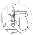
図2において、類似のリーフシール組立体が内側シュラウドに取り付けられている。この形の場合は、ステータシュラウドセグメント68は、それぞれの前端縁及び後端縁に沿った一対のグルーブ72及び73をもつ外側シュラウド70を含む。内部シュラウド74は、外側シュラウド70のそれぞれグルーブ72及び73に係合するための一対のフランジ76及び78をもつ。全体を80で示すリーフシール組立体は、内側シュラウド74の後端縁に沿って形成される座部、例えば溝部に固定される。先の実施形態と同様に、シール組立体80は、シールプレート84及び一対のばねクリップ86を含み、ばねクリップ及びシールプレート84は、溝部の両端に隣接した、シール組立体を内側シュラウド74の溝部82の中に固定するためのピン89を受け入れる位置合わされた孔をもつ。また先の実施形態と同様に、バンプ83が、プレート84の後面に沿って形成され、プレートがタービンロータ軸線に垂直になり、ノズルバンド90の前端縁側壁88のフランジに対して効果的なシール係合をするようにするための支点としての機能を果たす。
【0012】
現在最も実用的で好ましい実施例と考えられるものに関連して本発明を記述してきたが、本発明は、開示した実施例に限定されるものではなく、逆に、特許請求の範囲の技術思想と技術的範囲に含まれる様々な変更及び均等構成を網羅するものと理解されたい。
【図面の簡単な説明】
【図1】 本発明の好ましい実施形態により構成されたリーフシール組立体をもつシュラウドセグメントの、分り易くするために部品を引き離して示す斜視図。
【図2】 シュラウドセグメントの内側シュラウドと共に使用するリーフシール組立体の破断側面図。
【図3】 図1及び図3に示すシュラウドセグメントの外側シュラウドと共に使用するリーフシール組立体を示す図2と類似の側面図。
【図4】 図1及び図3のリーフシール組立体の拡大側面図。
【符号の説明】
10,68 シュラウドセグメント
12,70 外側シュラウド
14,74 内側シュラウド
16,18 フック
20,22,72,73 グルーブ
32 タービンハウジングのフック
33 高温ガス通路
35 バケット
37 空洞
40,80 リーフシール組立体
42,88 フランジ
45,90 ノズル外側バンド
46,82 溝部
50,84 リーフシールプレート
54 リーフシールプレートの孔
56,86 ばねクリップ
57,83 突起
58 ばねクリップの孔
60,89 ピン
76,78 フランジ[0001]
BACKGROUND OF THE INVENTION
The present invention relates to a seal for sealing between a stator shroud and a nozzle wall leading edge along an outer band of a nozzle segment that defines a portion of a hot gas path through a gas turbine.
[0002]
[Prior art]
In industrial gas turbines, the shroud segments are secured in an annular row to the hooks of the turbine housing and form an annular shroud radially outward and adjacent the tip of a bucket that forms part of the turbine rotor. The inner wall of the shroud defines part of the gas passage. Generally, the nozzle is hooked into the radial groove of the shroud segment. However, the front and rear cavities of the shroud segment are higher than the pressure in the gas passage, and significant leakage into the hot gas passage often occurs. These cavities are generally pressurized by compressor exhaust air, and this air leakage is undesirable for turbine performance and emissions. Leakage is increased in those nozzle stages with discontinuous nozzle leading edge hooks. That is, the gap between the hook and the edge of the adjacent shroud becomes a large leakage passage for the compressor exhaust air flowing into the hot gas flow path.
[0003]
[Problems to be solved by the invention]
Therefore, it is desirable to provide an effective seal between the stator shroud segment and the nozzle wall and minimize leakage into the hot gas path, particularly in turbines with discontinuous nozzle hooks.
[0004]
[Means for Solving the Problems]
According to a preferred embodiment of the present invention, a shroud device is provided that provides an effective seal between the shroud segment and the nozzle band sidewall, particularly the front edge wall of the nozzle band. Specifically, the inner and outer shrouds include hooks and grooves in complementary relationship adjacent to the front and rear edges of each shroud, joining the inner and outer shrouds together. The outer shroud is then secured to the hook of the turbine housing. In a preferred embodiment, each shroud segment has one outer shroud and two inner shrouds. The shroud segments form an annular row around them about the turbine rotor axis and constitute a shroud set. More specifically, the front edge of the adjacent nozzle band sidewall has a forward protrusion or “knob” that joins the shroud leaf seal adjacent the rear edge of the shroud segment. The leaf seal can be attached to either the two inner shrouds or the outer shroud. The leaf seal extends in the circumferential direction of the shroud segment and is spring loaded rearward by a pair of spring clips. The leaf seal and spring clip are pinned to the shroud segment in a radially outwardly extending groove along the shroud segment. In order to allow for minimal leakage using a leaf seal that engages a knob or flange on the nozzle's outer band leading edge sidewall, the leaf seal extends perpendicular to the centerline of the operating turbine. The fulcrum is supported by the shroud segment. The seal also includes an overlap, each overlap sealing between adjacent leaf seals of adjacent segments.
[0005]
According to a preferred embodiment of the present invention, said gas turbine for substantially preventing leakage between the pressurized cavity on one side of the seal and the hot gas in the hot gas passage of the gas turbine on the other side of the seal A seal is provided for sealing between the stator shroud of the turbine and the nozzle, the seal defining a portion of the hot gas passage and a surface located over the tip of the bucket that forms part of the turbine rotor A shroud segment, an outer band defining a portion of a hot gas path, forming a portion of a turbine nozzle, a leaf seal between the shroud segment and the nozzle outer band, and a shroud segment and a leaf seal A spring that engages and biases the leaf seal into sealing engagement with the nozzle outer band.
[0006]
According to a further preferred embodiment of the invention, said gas for substantially preventing leakage between the pressurized cavity on one side of the seal and the hot gas in the hot gas passage of the gas turbine on the other side of the seal A seal is provided for sealing between the turbine stator shroud and the nozzle, the seal defining a portion of the hot gas passage and positioned over the tip of a bucket that forms part of the turbine rotor. A shroud segment having a surface and having a leading edge and a trailing edge; an outer band defining part of the hot gas path and forming part of the turbine nozzle; and the trailing edge of the shroud segment and the nozzle outer A leaf seal located between the front edge of the band and received in the seat of the shroud segment, engaging the shroud segment and the leaf seal, The portion of the seal including a spring biasing to the front edge wall and sealing engagement of the nozzle outer band.
[0007]
DETAILED DESCRIPTION OF THE INVENTION
In the drawing, and in particular in FIG. 1, a shroud segment, generally indicated at 10, is shown. The
[0008]
1 and 3, a leaf seal assembly, generally indicated at 40, is provided along the rear edge of the
[0009]
The
[0010]
To incorporate the leaf seal assembly, the outer and inner shrouds are joined together with
[0011]
In FIG. 2, a similar leaf seal assembly is attached to the inner shroud. In this form, the
[0012]
Although the present invention has been described in connection with what is presently considered to be the most practical and preferred embodiments, the invention is not limited to the disclosed embodiments, but conversely, the technical spirit of the claims It should be understood that the invention covers various modifications and equivalent configurations included in the technical scope.
[Brief description of the drawings]
FIG. 1 is a perspective view of a shroud segment having a leaf seal assembly constructed in accordance with a preferred embodiment of the present invention, with parts separated for ease of understanding.
FIG. 2 is a cutaway side view of a leaf seal assembly for use with an inner shroud of a shroud segment.
3 is a side view similar to FIG. 2 showing a leaf seal assembly for use with the outer shroud of the shroud segment shown in FIGS. 1 and 3; FIG.
4 is an enlarged side view of the leaf seal assembly of FIGS. 1 and 3. FIG.
[Explanation of symbols]
10, 68
Claims (8)
前記高温ガス通路の一部を画成するシュラウドセグメント(10)であって、タービンロータの一部を構成するバッケット(35)の先端を覆って位置する表面(31)を有し、前端縁と後端縁とを有するシュラウドセグメント(10)と、
前記高温ガス通路の一部を画成し、前記タービンのノズル(45)の一部を構成する外側バンド(45)と、
前記シュラウドセグメント(10)の後端縁と前記ノズル外側バンド(45)の前端縁側壁との間に位置するリーフシール(50)であって、同シュラウドセグメント(10)の後縁端の溝の座部(46)に受け入れられるリーフシール(50)と、
前記シュラウドセグメント(10)の前記溝に保持され、同シュラウドセグメント(10)及び前記リーフシール(50)に係合して、同リーフシール(50)の一部を前記ノズル外側バンド(45)の前端縁側壁とシール係合するように付勢するスプリング(56)と、
を含む、シール。Seal between the gas turbine stator shroud (10) and the nozzle (45) to leak between the pressurized cavity on one side of the seal and the hot gas in the hot gas passage of the gas turbine on the other side of the seal. the a seal for prevention (40),
A shroud segment (10) defining a portion of the hot gas passage, having a surface (31) located over the tip of a bucket (35) forming a portion of the turbine rotor; A shroud segment (10) having a trailing edge;
An outer band (45) defining a portion of the hot gas path and forming a portion of the nozzle (45) of the turbine;
A leaf seal (50) positioned between a rear end edge of the shroud segment (10) and a front end edge side wall of the nozzle outer band (45), the groove of the rear end edge of the shroud segment (10) A leaf seal (50) received in the seat (46);
A portion of the leaf seal (50) is held in the groove of the shroud segment (10) and engaged with the shroud segment (10) and the leaf seal (50). A spring (56) biasing into sealing engagement with the front edge sidewall;
Including, seal.
Applications Claiming Priority (2)
| Application Number | Priority Date | Filing Date | Title |
|---|---|---|---|
| US09/571814 | 2000-05-16 | ||
| US09/571,814 US6402466B1 (en) | 2000-05-16 | 2000-05-16 | Leaf seal for gas turbine stator shrouds and a nozzle band |
Publications (3)
| Publication Number | Publication Date |
|---|---|
| JP2001323804A JP2001323804A (en) | 2001-11-22 |
| JP2001323804A5 JP2001323804A5 (en) | 2008-02-28 |
| JP4721524B2 true JP4721524B2 (en) | 2011-07-13 |
Family
ID=24285177
Family Applications (1)
| Application Number | Title | Priority Date | Filing Date |
|---|---|---|---|
| JP2001005839A Expired - Fee Related JP4721524B2 (en) | 2000-05-16 | 2001-01-15 | Leaf seal for gas turbine stator shroud and nozzle band |
Country Status (7)
| Country | Link |
|---|---|
| US (1) | US6402466B1 (en) |
| EP (1) | EP1156188B1 (en) |
| JP (1) | JP4721524B2 (en) |
| KR (1) | KR20010105147A (en) |
| AT (1) | ATE398229T1 (en) |
| CZ (1) | CZ200143A3 (en) |
| DE (1) | DE60134360D1 (en) |
Families Citing this family (72)
| Publication number | Priority date | Publication date | Assignee | Title |
|---|---|---|---|---|
| US6464457B1 (en) * | 2001-06-21 | 2002-10-15 | General Electric Company | Turbine leaf seal mounting with headless pins |
| US6752592B2 (en) | 2001-12-28 | 2004-06-22 | General Electric Company | Supplemental seal for the chordal hinge seals in a gas turbine |
| US6659472B2 (en) | 2001-12-28 | 2003-12-09 | General Electric Company | Seal for gas turbine nozzle and shroud interface |
| US6764081B2 (en) * | 2001-12-28 | 2004-07-20 | General Electric Company | Supplemental seal for the chordal hinge seals in a gas turbine and methods of installation |
| JP3840556B2 (en) * | 2002-08-22 | 2006-11-01 | 川崎重工業株式会社 | Combustor liner seal structure |
| US6733234B2 (en) | 2002-09-13 | 2004-05-11 | Siemens Westinghouse Power Corporation | Biased wear resistant turbine seal assembly |
| US6883807B2 (en) | 2002-09-13 | 2005-04-26 | Seimens Westinghouse Power Corporation | Multidirectional turbine shim seal |
| US7093837B2 (en) | 2002-09-26 | 2006-08-22 | Siemens Westinghouse Power Corporation | Turbine spring clip seal |
| US6939106B2 (en) * | 2002-12-11 | 2005-09-06 | General Electric Company | Sealing of steam turbine nozzle hook leakages using a braided rope seal |
| US6832892B2 (en) | 2002-12-11 | 2004-12-21 | General Electric Company | Sealing of steam turbine bucket hook leakages using a braided rope seal |
| US6814538B2 (en) | 2003-01-22 | 2004-11-09 | General Electric Company | Turbine stage one shroud configuration and method for service enhancement |
| DE10306915A1 (en) * | 2003-02-19 | 2004-09-02 | Alstom Technology Ltd | Seal for use between segments of gas turbine shrouds comprises strip with apertures for passage of gas in pattern designed so that when strip shifts sideways their free cross-section remains constant |
| US6869082B2 (en) * | 2003-06-12 | 2005-03-22 | Siemens Westinghouse Power Corporation | Turbine spring clip seal |
| US7086829B2 (en) | 2004-02-03 | 2006-08-08 | General Electric Company | Film cooling for the trailing edge of a steam cooled nozzle |
| EP1718890B1 (en) * | 2004-02-25 | 2015-09-16 | BUCKNELL, John Wentworth | Seals for hydraulic assemblies |
| FR2868125B1 (en) * | 2004-03-26 | 2006-07-21 | Snecma Moteurs Sa | TURBOMACHINE COMPRISING TWO SUBASSEMBLIES ASSEMBLED WITH AXIAL CONSTRAINTS |
| US7217089B2 (en) * | 2005-01-14 | 2007-05-15 | Pratt & Whitney Canada Corp. | Gas turbine engine shroud sealing arrangement |
| US7374395B2 (en) * | 2005-07-19 | 2008-05-20 | Pratt & Whitney Canada Corp. | Turbine shroud segment feather seal located in radial shroud legs |
| US7338253B2 (en) * | 2005-09-15 | 2008-03-04 | General Electric Company | Resilient seal on trailing edge of turbine inner shroud and method for shroud post impingement cavity sealing |
| DE102006017377A1 (en) * | 2006-04-11 | 2007-11-08 | Rolls-Royce Deutschland Ltd & Co Kg | Flap seal for a turbomachine |
| US7524167B2 (en) * | 2006-05-04 | 2009-04-28 | Siemens Energy, Inc. | Combustor spring clip seal system |
| US7811054B2 (en) | 2007-05-30 | 2010-10-12 | General Electric Company | Shroud configuration having sloped seal |
| US20090110546A1 (en) * | 2007-10-29 | 2009-04-30 | United Technologies Corp. | Feather Seals and Gas Turbine Engine Systems Involving Such Seals |
| FR2923525B1 (en) * | 2007-11-13 | 2009-12-18 | Snecma | SEALING A ROTOR RING IN A TURBINE FLOOR |
| US8469656B1 (en) | 2008-01-15 | 2013-06-25 | Siemens Energy, Inc. | Airfoil seal system for gas turbine engine |
| US8500394B2 (en) | 2008-02-20 | 2013-08-06 | United Technologies Corporation | Single channel inner diameter shroud with lightweight inner core |
| US8118548B2 (en) * | 2008-09-15 | 2012-02-21 | General Electric Company | Shroud for a turbomachine |
| US20100072710A1 (en) * | 2008-09-22 | 2010-03-25 | General Electric Company | Gas Turbine Seal |
| US8075255B2 (en) * | 2009-03-31 | 2011-12-13 | General Electric Company | Reducing inter-seal gap in gas turbine |
| US20110031704A1 (en) * | 2009-05-15 | 2011-02-10 | Lehr Brian C | Segmented Gaskets |
| FR2949810B1 (en) * | 2009-09-04 | 2013-06-28 | Turbomeca | DEVICE FOR SUPPORTING A TURBINE RING, TURBINE WITH SUCH A DEVICE AND TURBOMOTOR WITH SUCH A TURBINE |
| US8398090B2 (en) | 2010-06-09 | 2013-03-19 | General Electric Company | Spring loaded seal assembly for turbines |
| US9206904B2 (en) * | 2010-07-08 | 2015-12-08 | Siemens Energy, Inc. | Seal including flexible seal strips |
| EP2508713A1 (en) * | 2011-04-04 | 2012-10-10 | Siemens Aktiengesellschaft | Gas turbine comprising a heat shield and method of operation |
| US9115585B2 (en) * | 2011-06-06 | 2015-08-25 | General Electric Company | Seal assembly for gas turbine |
| US9016695B2 (en) * | 2011-08-02 | 2015-04-28 | United Technologies Corporation | Gas turbine exhaust nozzle divergent flap seal |
| US9726043B2 (en) | 2011-12-15 | 2017-08-08 | General Electric Company | Mounting apparatus for low-ductility turbine shroud |
| US9145789B2 (en) * | 2012-09-05 | 2015-09-29 | General Electric Company | Impingement plate for damping and cooling shroud assembly inter segment seals |
| US9416671B2 (en) * | 2012-10-04 | 2016-08-16 | General Electric Company | Bimetallic turbine shroud and method of fabricating |
| US9863264B2 (en) * | 2012-12-10 | 2018-01-09 | General Electric Company | Turbine shroud engagement arrangement and method |
| US10087771B2 (en) * | 2013-02-20 | 2018-10-02 | United Technologies Corporation | Gas turbine engine seal assembly |
| US10100737B2 (en) | 2013-05-16 | 2018-10-16 | Siemens Energy, Inc. | Impingement cooling arrangement having a snap-in plate |
| JP6114878B2 (en) | 2013-05-17 | 2017-04-12 | ゼネラル・エレクトリック・カンパニイ | CMC shroud support system |
| WO2014189873A2 (en) | 2013-05-21 | 2014-11-27 | Siemens Energy, Inc. | Gas turbine ring segment cooling apparatus |
| WO2015009392A2 (en) * | 2013-07-19 | 2015-01-22 | General Electric Comapny | Turbine nozzle with impingement baffle |
| JP6529013B2 (en) | 2013-12-12 | 2019-06-12 | ゼネラル・エレクトリック・カンパニイ | CMC shroud support system |
| US9856737B2 (en) * | 2014-03-27 | 2018-01-02 | United Technologies Corporation | Blades and blade dampers for gas turbine engines |
| CN106460543B (en) | 2014-06-12 | 2018-12-21 | 通用电气公司 | Multi-piece type shield hangs device assembly |
| EP3155231B1 (en) | 2014-06-12 | 2019-07-03 | General Electric Company | Shroud hanger assembly |
| CN106460560B (en) | 2014-06-12 | 2018-11-13 | 通用电气公司 | Shield hanging holder set |
| EP2960439A1 (en) * | 2014-06-26 | 2015-12-30 | Siemens Aktiengesellschaft | Turbomachine with an outer sealing and use of the turbomachine |
| US10161259B2 (en) * | 2014-10-28 | 2018-12-25 | General Electric Company | Flexible film-riding seal |
| US9845696B2 (en) * | 2014-12-15 | 2017-12-19 | Pratt & Whitney Canada Corp. | Turbine shroud sealing architecture |
| US10280777B2 (en) | 2014-12-19 | 2019-05-07 | General Electric Company | System and method including a circumferential seal assembly to facilitate sealing in a turbine |
| KR101584156B1 (en) | 2014-12-22 | 2016-01-22 | 주식회사 포스코 | Seal for gas turbine and seal assembly having the same |
| US9874104B2 (en) | 2015-02-27 | 2018-01-23 | General Electric Company | Method and system for a ceramic matrix composite shroud hanger assembly |
| US10260364B2 (en) | 2015-03-09 | 2019-04-16 | United Technologies Corporation | Sliding seal |
| US10202862B2 (en) * | 2015-04-08 | 2019-02-12 | United Technologies Corporation | Sliding seal |
| EP3091188B1 (en) * | 2015-05-08 | 2018-08-01 | MTU Aero Engines GmbH | Flow engine with a sealing arrangement |
| US10393147B2 (en) * | 2015-07-23 | 2019-08-27 | Unison Industries, Llc | Fan casing assemblies and method of mounting a cooler to a fan casing |
| US11473437B2 (en) * | 2015-09-24 | 2022-10-18 | General Electric Company | Turbine snap in spring seal |
| US10036269B2 (en) * | 2015-10-23 | 2018-07-31 | General Electric Company | Leaf seal reach over spring with retention mechanism |
| US10087768B2 (en) * | 2015-12-07 | 2018-10-02 | General Electric Company | Steam turbine rotor seal key member, related assembly and steam turbine |
| US10450883B2 (en) | 2016-10-31 | 2019-10-22 | United Technologies Corporation | W-seal shield for interrupted cavity |
| US10408090B2 (en) | 2016-11-17 | 2019-09-10 | United Technologies Corporation | Gas turbine engine article with panel retained by preloaded compliant member |
| DE102016223867A1 (en) | 2016-11-30 | 2018-05-30 | MTU Aero Engines AG | Turbomachinery sealing arrangement |
| US11008894B2 (en) | 2018-10-31 | 2021-05-18 | Raytheon Technologies Corporation | BOAS spring clip |
| US10934877B2 (en) * | 2018-10-31 | 2021-03-02 | Raytheon Technologies Corporation | CMC laminate pocket BOAS with axial attachment scheme |
| US11136896B2 (en) | 2019-04-24 | 2021-10-05 | Raytheon Technologies Corporation | Rotating leaf spring seal |
| FR3095830B1 (en) * | 2019-05-10 | 2021-05-07 | Safran Aircraft Engines | TURBOMACHINE MODULE EQUIPPED WITH A SEALING FLAP HOLDING DEVICE |
| CN110284929B (en) * | 2019-07-19 | 2021-10-22 | 中国航发沈阳发动机研究所 | Turbine cartridge receiver structure of obturaging |
| US11761342B2 (en) * | 2020-10-26 | 2023-09-19 | General Electric Company | Sealing assembly for a gas turbine engine having a leaf seal |
Citations (7)
| Publication number | Priority date | Publication date | Assignee | Title |
|---|---|---|---|---|
| JPS5376207A (en) * | 1976-12-16 | 1978-07-06 | Gen Electric | Nozzle of turbine |
| JPH0351578A (en) * | 1989-07-10 | 1991-03-05 | General Electric Co <Ge> | Leaf seal |
| US5330321A (en) * | 1992-05-19 | 1994-07-19 | Rolls Royce Plc | Rotor shroud assembly |
| JPH09112206A (en) * | 1995-10-23 | 1997-04-28 | United Technol Corp <Utc> | Shroud for rotor assembly |
| US5797723A (en) * | 1996-11-13 | 1998-08-25 | General Electric Company | Turbine flowpath seal |
| JPH1162509A (en) * | 1997-08-18 | 1999-03-05 | Ishikawajima Harima Heavy Ind Co Ltd | Turbine shroud support structure of jet engine |
| JPH11343809A (en) * | 1998-06-02 | 1999-12-14 | Ishikawajima Harima Heavy Ind Co Ltd | Sealing structure of turbine shroud part for gas turbine |
Family Cites Families (14)
| Publication number | Priority date | Publication date | Assignee | Title |
|---|---|---|---|---|
| US4184689A (en) * | 1978-10-02 | 1980-01-22 | United Technologies Corporation | Seal structure for an axial flow rotary machine |
| US4314793A (en) * | 1978-12-20 | 1982-02-09 | United Technologies Corporation | Temperature actuated turbine seal |
| US5118120A (en) * | 1989-07-10 | 1992-06-02 | General Electric Company | Leaf seals |
| GB2239678B (en) * | 1989-12-08 | 1993-03-03 | Rolls Royce Plc | Gas turbine engine blade shroud assembly |
| US5211407A (en) * | 1992-04-30 | 1993-05-18 | General Electric Company | Compressor rotor cross shank leak seal for axial dovetails |
| US5333992A (en) * | 1993-02-05 | 1994-08-02 | United Technologies Corporation | Coolable outer air seal assembly for a gas turbine engine |
| FR2728016B1 (en) * | 1994-12-07 | 1997-01-17 | Snecma | NON-SECTORIZED MONOBLOCK DISTRIBUTOR OF A TURBOMACHINE TURBINE STATOR |
| US5562408A (en) * | 1995-06-06 | 1996-10-08 | General Electric Company | Isolated turbine shroud |
| GB9612441D0 (en) * | 1996-06-14 | 1996-08-14 | Guest John D | Improvements in or relating to tube coupling bodies |
| US6076835A (en) * | 1997-05-21 | 2000-06-20 | Allison Advanced Development Company | Interstage van seal apparatus |
| US5971703A (en) * | 1997-12-05 | 1999-10-26 | Pratt & Whitney Canada Inc. | Seal assembly for a gas turbine engine |
| FR2780443B1 (en) * | 1998-06-25 | 2000-08-04 | Snecma | HIGH PRESSURE TURBINE STATOR RING OF A TURBOMACHINE |
| US6126389A (en) * | 1998-09-02 | 2000-10-03 | General Electric Co. | Impingement cooling for the shroud of a gas turbine |
| US6164656A (en) * | 1999-01-29 | 2000-12-26 | General Electric Company | Turbine nozzle interface seal and methods |
-
2000
- 2000-05-16 US US09/571,814 patent/US6402466B1/en not_active Expired - Lifetime
-
2001
- 2001-01-04 CZ CZ200143A patent/CZ200143A3/en unknown
- 2001-01-12 KR KR1020010001724A patent/KR20010105147A/en not_active Application Discontinuation
- 2001-01-15 JP JP2001005839A patent/JP4721524B2/en not_active Expired - Fee Related
- 2001-01-16 AT AT01300367T patent/ATE398229T1/en not_active IP Right Cessation
- 2001-01-16 DE DE60134360T patent/DE60134360D1/en not_active Expired - Lifetime
- 2001-01-16 EP EP01300367A patent/EP1156188B1/en not_active Expired - Lifetime
Patent Citations (7)
| Publication number | Priority date | Publication date | Assignee | Title |
|---|---|---|---|---|
| JPS5376207A (en) * | 1976-12-16 | 1978-07-06 | Gen Electric | Nozzle of turbine |
| JPH0351578A (en) * | 1989-07-10 | 1991-03-05 | General Electric Co <Ge> | Leaf seal |
| US5330321A (en) * | 1992-05-19 | 1994-07-19 | Rolls Royce Plc | Rotor shroud assembly |
| JPH09112206A (en) * | 1995-10-23 | 1997-04-28 | United Technol Corp <Utc> | Shroud for rotor assembly |
| US5797723A (en) * | 1996-11-13 | 1998-08-25 | General Electric Company | Turbine flowpath seal |
| JPH1162509A (en) * | 1997-08-18 | 1999-03-05 | Ishikawajima Harima Heavy Ind Co Ltd | Turbine shroud support structure of jet engine |
| JPH11343809A (en) * | 1998-06-02 | 1999-12-14 | Ishikawajima Harima Heavy Ind Co Ltd | Sealing structure of turbine shroud part for gas turbine |
Also Published As
| Publication number | Publication date |
|---|---|
| DE60134360D1 (en) | 2008-07-24 |
| ATE398229T1 (en) | 2008-07-15 |
| EP1156188A2 (en) | 2001-11-21 |
| JP2001323804A (en) | 2001-11-22 |
| KR20010105147A (en) | 2001-11-28 |
| EP1156188B1 (en) | 2008-06-11 |
| US6402466B1 (en) | 2002-06-11 |
| EP1156188A3 (en) | 2003-09-24 |
| CZ200143A3 (en) | 2002-01-16 |
Similar Documents
| Publication | Publication Date | Title |
|---|---|---|
| JP4721524B2 (en) | Leaf seal for gas turbine stator shroud and nozzle band | |
| JP5154788B2 (en) | Seal assembly and turbine nozzle assembly | |
| KR100681560B1 (en) | Seal for gas turbine nozzle and shroud interface | |
| JP4268800B2 (en) | Auxiliary seal for string hinge seal in gas turbine | |
| JP4130581B2 (en) | Auxiliary seal for string hinge seal in gas turbine | |
| JP3912935B2 (en) | High-pressure turbine stator ring for turbine engines | |
| JP4205421B2 (en) | Auxiliary seal for string hinge seal in gas turbine | |
| JP4315320B2 (en) | Auxiliary seal for string hinge seal in gas turbine | |
| JP4960065B2 (en) | Method and apparatus for assembling a turbine engine | |
| JP5905676B2 (en) | Transition piece sealing shim | |
| US9506374B2 (en) | Component of a turbine with leaf seals and method for sealing against leakage between a vane and a carrier element | |
| JP2009108857A (en) | Gas turbine including flexible chordal hinge seal | |
| JP2007513281A (en) | Peristaltic joint between combustor wall and nozzle platform | |
| JP4130580B2 (en) | Auxiliary seal for string hinge seal in gas turbine | |
| US8888445B2 (en) | Turbomachine seal assembly | |
| JP4293419B2 (en) | Auxiliary seal for string hinge seal in gas turbine | |
| US6637753B2 (en) | Supplemental seal for the chordal hinge seals in a gas turbine | |
| JP4248871B2 (en) | Auxiliary seal for string hinge seal in gas turbine | |
| JP2003222030A (en) | Supplemental seal for chordal hinge seal in gas turbine and method of installation | |
| JPH09133003A (en) | Integral shroud blade | |
| JP2600955B2 (en) | Double-flow steam turbine | |
| JP2000274261A (en) | Gas turbine | |
| JP2001303907A (en) | Shroud support structure for gas turbine engine |
Legal Events
| Date | Code | Title | Description |
|---|---|---|---|
| A521 | Request for written amendment filed |
Free format text: JAPANESE INTERMEDIATE CODE: A523 Effective date: 20080115 |
|
| A621 | Written request for application examination |
Free format text: JAPANESE INTERMEDIATE CODE: A621 Effective date: 20080115 |
|
| A131 | Notification of reasons for refusal |
Free format text: JAPANESE INTERMEDIATE CODE: A131 Effective date: 20100427 |
|
| A601 | Written request for extension of time |
Free format text: JAPANESE INTERMEDIATE CODE: A601 Effective date: 20100727 |
|
| RD02 | Notification of acceptance of power of attorney |
Free format text: JAPANESE INTERMEDIATE CODE: A7422 Effective date: 20100727 |
|
| RD04 | Notification of resignation of power of attorney |
Free format text: JAPANESE INTERMEDIATE CODE: A7424 Effective date: 20100727 |
|
| A521 | Request for written amendment filed |
Free format text: JAPANESE INTERMEDIATE CODE: A523 Effective date: 20100826 |
|
| A601 | Written request for extension of time |
Free format text: JAPANESE INTERMEDIATE CODE: A601 Effective date: 20100827 |
|
| A602 | Written permission of extension of time |
Free format text: JAPANESE INTERMEDIATE CODE: A602 Effective date: 20100816 |
|
| A602 | Written permission of extension of time |
Free format text: JAPANESE INTERMEDIATE CODE: A602 Effective date: 20100901 |
|
| A521 | Request for written amendment filed |
Free format text: JAPANESE INTERMEDIATE CODE: A523 Effective date: 20101027 |
|
| A521 | Request for written amendment filed |
Free format text: JAPANESE INTERMEDIATE CODE: A523 Effective date: 20101111 |
|
| TRDD | Decision of grant or rejection written | ||
| A01 | Written decision to grant a patent or to grant a registration (utility model) |
Free format text: JAPANESE INTERMEDIATE CODE: A01 Effective date: 20110308 |
|
| A61 | First payment of annual fees (during grant procedure) |
Free format text: JAPANESE INTERMEDIATE CODE: A61 Effective date: 20110405 |
|
| FPAY | Renewal fee payment (event date is renewal date of database) |
Free format text: PAYMENT UNTIL: 20140415 Year of fee payment: 3 |
|
| R150 | Certificate of patent or registration of utility model |
Ref document number: 4721524 Country of ref document: JP Free format text: JAPANESE INTERMEDIATE CODE: R150 Free format text: JAPANESE INTERMEDIATE CODE: R150 |
|
| R250 | Receipt of annual fees |
Free format text: JAPANESE INTERMEDIATE CODE: R250 |
|
| R250 | Receipt of annual fees |
Free format text: JAPANESE INTERMEDIATE CODE: R250 |
|
| R250 | Receipt of annual fees |
Free format text: JAPANESE INTERMEDIATE CODE: R250 |
|
| R250 | Receipt of annual fees |
Free format text: JAPANESE INTERMEDIATE CODE: R250 |
|
| R250 | Receipt of annual fees |
Free format text: JAPANESE INTERMEDIATE CODE: R250 |
|
| LAPS | Cancellation because of no payment of annual fees |