JP4721418B2 - Imaging apparatus and control method thereof - Google Patents

Imaging apparatus and control method thereof Download PDF

Info

Publication number
JP4721418B2
JP4721418B2 JP2005264436A JP2005264436A JP4721418B2 JP 4721418 B2 JP4721418 B2 JP 4721418B2 JP 2005264436 A JP2005264436 A JP 2005264436A JP 2005264436 A JP2005264436 A JP 2005264436A JP 4721418 B2 JP4721418 B2 JP 4721418B2
Authority
JP
Japan
Prior art keywords
image
image data
imaging
communication
unit
Prior art date
Legal status (The legal status is an assumption and is not a legal conclusion. Google has not performed a legal analysis and makes no representation as to the accuracy of the status listed.)
Expired - Fee Related
Application number
JP2005264436A
Other languages
Japanese (ja)
Other versions
JP2007081585A5 (en
JP2007081585A (en
Inventor
洋一 山岸
Current Assignee (The listed assignees may be inaccurate. Google has not performed a legal analysis and makes no representation or warranty as to the accuracy of the list.)
Canon Inc
Original Assignee
Canon Inc
Priority date (The priority date is an assumption and is not a legal conclusion. Google has not performed a legal analysis and makes no representation as to the accuracy of the date listed.)
Filing date
Publication date
Application filed by Canon Inc filed Critical Canon Inc
Priority to JP2005264436A priority Critical patent/JP4721418B2/en
Publication of JP2007081585A publication Critical patent/JP2007081585A/en
Publication of JP2007081585A5 publication Critical patent/JP2007081585A5/ja
Application granted granted Critical
Publication of JP4721418B2 publication Critical patent/JP4721418B2/en
Expired - Fee Related legal-status Critical Current
Anticipated expiration legal-status Critical

Links

Images

Landscapes

  • Television Signal Processing For Recording (AREA)
  • Studio Devices (AREA)
  • Signal Processing For Digital Recording And Reproducing (AREA)

Description

本発明は、静止画像や動画像を撮像し、撮像した画像を記憶、通信、記録、再生可能な撮像装置及びその制御方法に関する。   The present invention relates to an imaging apparatus capable of capturing still images and moving images and storing, communicating, recording, and reproducing the captured images, and a control method thereof.

従来、固体メモリ素子を有するメモリカードを記録媒体として、静止画像や動画像を記録再生する電子カメラ等の撮像装置は既に市販されている。更に、音声データや画像データを通信・保存するパソコン等の画像処理装置も販売されている。   Conventionally, an imaging device such as an electronic camera that records and reproduces still images and moving images using a memory card having a solid-state memory element as a recording medium is already on the market. Furthermore, image processing apparatuses such as personal computers that communicate and store audio data and image data are also on the market.

これらの電子カメラやパソコンからなる撮像システムを携行することにより、事務所や家庭等の屋内での作業に拘束されずに、屋外において機動的な業務推進を行うことが可能となっている。   By carrying an imaging system composed of these electronic cameras and personal computers, it is possible to perform flexible business promotion outdoors without being constrained by indoor work such as offices and homes.

特に、通信機能を備えた電子カメラにより撮影した画像データを、通信機能を備えたパソコンに無線通信を用いて転送するなど、電子カメラとパソコンを協調して動作させることにより、利便性の良い撮像システムを構築することが可能となっている。   In particular, image data captured by an electronic camera equipped with a communication function is transferred to a personal computer equipped with a communication function using wireless communication. It is possible to build a system.

特開2000−115669号公報JP 2000-115669 A

しかしながら、特に電子カメラとパソコンが無線通信により接続される場合、次のような問題があった。即ち、電子カメラの使用者がシャッターボタンを押して撮影した画像が確実に保存されることを期待しているにも関わらず、転送が完了する前に無線状況が悪化して無線通信が切断されてしまい、画像データが転送できなくなってしまうことがあった。その場合、撮影した画像が記録媒体に記録されず、また、無線切断のために画像処理装置にも転送・保存されずに消失してしまう。   However, particularly when the electronic camera and the personal computer are connected by wireless communication, there are the following problems. In other words, even though the user of the electronic camera expects that the image captured by pressing the shutter button will be saved reliably, the wireless situation will deteriorate and the wireless communication will be disconnected before the transfer is completed. As a result, the image data may not be transferred. In that case, the photographed image is not recorded on the recording medium, and is lost without being transferred or stored in the image processing apparatus due to wireless disconnection.

また、記憶媒体を使用可能な電子カメラも存在するが、記憶媒体の空き容量が足りなくなったり、記憶媒体が電子カメラから外された時など、何らかの理由で記録媒体が使用できない状態にある場合には、同様の問題が生じていた。   In addition, there are electronic cameras that can use storage media, but the recording media cannot be used for some reason, such as when there is not enough free space on the storage media or when the storage media is removed from the electronic camera. Had a similar problem.

本発明は上記問題点を鑑みてなされたものであり、撮影した画像を無線通信により転送する場合に、撮影した画像の消失をできるだけ少なくすることを目的とする。   The present invention has been made in view of the above problems, and an object of the present invention is to minimize the disappearance of a photographed image when the photographed image is transferred by wireless communication.

上記目的を達成するために、本発明の撮像装置は、画像を撮影して該画像の画像データを出力する撮像手段と、前記撮像手段から出力された画像データを一時的に記憶する記憶手段と、前記記憶手段に画像データが残っているか否かを判断する第1の判断手段と、前記記憶手段に記憶した画像データを記録媒体に記録する記録手段と、前記記録手段が使用可能か否かを判断する第2の判断手段と、前記記憶手段に記憶された画像データまたは前記記録手段に記録された画像データを、通信により外部処理装置に転送するための通信手段と、前記記憶手段に記憶された画像データを前記通信手段により前記外部処理装置に転送する転送モードにおいて、前記第2の判断手段により前記記録手段が使用不可能であると判断され、且つ、前記第1の判断手段により前記記憶手段に画像データが残っていると判断された場合に、前記撮像手段による撮影を禁止する制御手段とを有する。 In order to achieve the above object, an imaging apparatus of the present invention includes an imaging unit that captures an image and outputs image data of the image , and a storage unit that temporarily stores the image data output from the imaging unit. First determination means for determining whether or not image data remains in the storage means, recording means for recording the image data stored in the storage means on a recording medium, and whether or not the recording means can be used Second determination means for determining the image data, communication means for transferring image data stored in the storage means or image data recorded in the recording means to an external processing device by communication, and storage in the storage means in the transfer mode for transferring image data to the external processing apparatus by the communication means, the second of said recording means by determining means is determined to be unusable, and the first If it is determined that image data remains in the memory means by the disconnection means, and a control means for prohibiting photography by the imaging means.

また、画像を撮影して該画像の画像データを出力する撮像手段と、前記撮像手段から出力された画像データを一時的に記憶する記憶手段と、該記憶手段に記憶した画像データを記録媒体に記録する記録手段と、外部処理装置と通信するための通信手段とを有する撮像装置の本発明の制御方法は、前記記録手段が使用可能か否かを判断する第1の判断ステップと、前記記憶手段に画像データが残っているか否かを判断する第2の判断ステップと、前記記憶手段に記憶された画像データを前記外部処理装置に転送する転送ステップと、前記転送ステップの実行中に、前記第1の判断ステップにより前記記録手段が使用不可能であると判断され、且つ、前記第2の判断ステップにより前記記憶手段に画像データが残っていると判断された場合に、前記撮像手段による撮影を禁止する制御ステップ
有する。
In addition, an imaging unit that captures an image and outputs the image data of the image, a storage unit that temporarily stores the image data output from the imaging unit , and image data stored in the storage unit are stored in a recording medium. According to the control method of the present invention for an imaging apparatus having a recording means for recording and a communication means for communicating with an external processing device, a first determination step for determining whether or not the recording means can be used, and the storage A second determination step for determining whether image data remains in the means, a transfer step for transferring the image data stored in the storage means to the external processing device, and during the execution of the transfer step, If it is determined in the first determination step that the recording means is unusable, and it is determined in the second determination step that image data remains in the storage means, A control step for prohibiting photography by the imaging means
Having.

本発明によれば、撮影した画像を無線通信により転送する場合に、撮影した画像の消失をできるだけ少なくすることができる。   ADVANTAGE OF THE INVENTION According to this invention, when the image | photographed image is transferred by radio | wireless communication, the loss | disappearance of the image | photographed image can be minimized.

以下、添付図面を参照して本発明を実施するための最良の形態を詳細に説明する。ただし、本形態において例示される構成部品の寸法、形状、それらの相対配置などは、本発明が適用される装置の構成や各種条件により適宜変更されるべきものであり、本発明がそれらの例示に限定されるものではない。   The best mode for carrying out the present invention will be described below in detail with reference to the accompanying drawings. However, the dimensions, shapes, relative arrangements, and the like of the components exemplified in the present embodiment should be changed as appropriate according to the configuration of the apparatus to which the present invention is applied and various conditions. It is not limited to.

図1は、本発明の実施の形態のシステムの全体構成を示す図である。   FIG. 1 is a diagram showing an overall configuration of a system according to an embodiment of the present invention.

図1において、100は撮像装置、200は記録媒体、300は画像処理装置である。   In FIG. 1, 100 is an imaging device, 200 is a recording medium, and 300 is an image processing device.

撮像装置100は通信回路110、アンテナ112を介して、画像処理装置300は通信回路330、アンテナ332を介して、無線通信により相互にコマンド、撮影画像を含むデータを送受している。   The imaging device 100 transmits and receives data including commands and captured images to each other by wireless communication via the communication circuit 110 and the antenna 112, and the image processing device 300 via the communication circuit 330 and the antenna 332.

撮像装置100と画像処理装置300間の無線通信は、IEEE802.11b、IEEE802.11g等の無線LAN通信、Bluetooth等のスペクトラム拡散方式等により行われている。   Wireless communication between the imaging apparatus 100 and the image processing apparatus 300 is performed by wireless LAN communication such as IEEE802.11b and IEEE802.11g, spread spectrum method such as Bluetooth, and the like.

撮像装置100は、レンズ310を通して撮像した画像データを通信回路110、アンテナ112、アンテナ332、通信回路330を介して、画像処理装置300に送信する。画像処理装置300は受信した画像データを着脱可能な記録媒体200に記録すると共に、通信回路326、アンテナ328を介して、他の画像処理装置或いは通信基地局に送信することができる。   The imaging apparatus 100 transmits image data captured through the lens 310 to the image processing apparatus 300 via the communication circuit 110, the antenna 112, the antenna 332, and the communication circuit 330. The image processing apparatus 300 can record the received image data on the detachable recording medium 200 and can transmit the image data to another image processing apparatus or a communication base station via the communication circuit 326 and the antenna 328.

<撮像装置100の構成説明>
図2は、本発明の実施の形態における画像処理機能を有する撮像装置100の構成を示すブロック図である。なお撮像装置100としては、デジタルカメラ、デジタルビデオカメラ、カメラ付き携帯端末(カメラ付き携帯電話を含む)等があり、何れであってもよい。
<Description of Configuration of Imaging Device 100>
FIG. 2 is a block diagram illustrating a configuration of the imaging apparatus 100 having an image processing function according to the embodiment of the present invention. Examples of the imaging apparatus 100 include a digital camera, a digital video camera, a camera-equipped mobile terminal (including a camera-equipped mobile phone), and the like.

図2において、10は撮影レンズ、12は絞り機能を備えるシャッター、14は光学像を電気信号に変換する撮像素子、16は撮像素子14のアナログ信号出力をディジタル信号に変換するA/D変換器である。   In FIG. 2, 10 is a photographing lens, 12 is a shutter having a diaphragm function, 14 is an image sensor that converts an optical image into an electric signal, and 16 is an A / D converter that converts an analog signal output from the image sensor 14 into a digital signal. It is.

18は撮像素子14、A/D変換器16、D/A変換器26にそれぞれクロック信号や制御信号を供給するタイミング発生回路であり、メモリ制御回路22及びシステム制御回路50により制御される。   A timing generation circuit 18 supplies a clock signal and a control signal to the image sensor 14, the A / D converter 16, and the D / A converter 26, respectively, and is controlled by the memory control circuit 22 and the system control circuit 50.

20は画像処理回路であり、A/D変換器16からのデータ或いはメモリ制御回路22からのデータに対して所定の画素補間処理や色変換処理を行う。また、画像処理回路20は、A/D変換器16から出力される画像データを用いて所定の演算処理を行う。そして、得られた演算結果に基づいてシステム制御回路50が露光制御部40、測距制御部42に対して、TTL(スルー・ザ・レンズ)方式のオートフォーカス(AF)処理、自動露出(AE)処理、フラッシュプリ発光(EF)処理を行っている。さらに、画像処理回路20は、A/D変換器16から出力される画像データを用いて所定の演算処理を行い、得られた演算結果に基づいてTTL方式のオートホワイトバランス(AWB)処理も行っている。   An image processing circuit 20 performs predetermined pixel interpolation processing and color conversion processing on the data from the A / D converter 16 or the data from the memory control circuit 22. Further, the image processing circuit 20 performs a predetermined calculation process using the image data output from the A / D converter 16. Then, based on the obtained calculation result, the system control circuit 50 performs TTL (through the lens) type autofocus (AF) processing, automatic exposure (AE) on the exposure control unit 40 and the distance measurement control unit 42. ) Processing and flash pre-emission (EF) processing. Further, the image processing circuit 20 performs predetermined arithmetic processing using the image data output from the A / D converter 16, and also performs TTL auto white balance (AWB) processing based on the obtained arithmetic result. ing.

22はメモリ制御回路であり、A/D変換器16、タイミング発生回路18、画像処理回路20、画像表示メモリ24、D/A変換器26、メモリ30、圧縮・伸長回路32を制御する。A/D変換器16から出力される画像データは、画像処理回路20、メモリ制御回路22を介して、或いはメモリ制御回路22のみを介して、画像表示メモリ24或いはメモリ30に書き込まれる。   A memory control circuit 22 controls the A / D converter 16, the timing generation circuit 18, the image processing circuit 20, the image display memory 24, the D / A converter 26, the memory 30, and the compression / decompression circuit 32. Image data output from the A / D converter 16 is written into the image display memory 24 or the memory 30 via the image processing circuit 20, the memory control circuit 22, or only through the memory control circuit 22.

24は画像表示メモリ、26はD/A変換器、28はTFT LCD等から成る画像表示部であり、画像表示メモリ24に書き込まれた表示用の画像データはD/A変換器26を介して画像表示部28により表示される。画像表示部28を用いて、撮像した画像データを逐次表示することで、電子ビューファインダー(EVF)機能を実現することができる。また、画像表示部28は、システム制御回路50の指示により任意に表示をON/OFFすることが可能であり、表示をOFFにした場合には撮像装置100の電力消費を大幅に低減することができる。   Reference numeral 24 denotes an image display memory, 26 denotes a D / A converter, 28 denotes an image display unit including a TFT LCD, and the image data for display written in the image display memory 24 passes through the D / A converter 26. Displayed by the image display unit 28. An electronic viewfinder (EVF) function can be realized by sequentially displaying captured image data using the image display unit 28. Further, the image display unit 28 can arbitrarily turn on / off the display according to an instruction from the system control circuit 50. When the display is turned off, the power consumption of the imaging apparatus 100 can be significantly reduced. it can.

30は撮影した静止画像や動画像を格納するための揮発性メモリ及び或いは不揮発性メモリからなるメモリであり、所定枚数の静止画像や所定時間の動画像を格納するのに十分な記憶容量を備えている。これにより、複数枚の静止画像を連続して撮影する連写撮影やパノラマ撮影の場合にも、高速かつ大量の画像書き込みをメモリ30に対して行うことが可能となる。また、メモリ30はシステム制御回路50の作業領域としても使用することが可能である。   Reference numeral 30 denotes a memory composed of a volatile memory and / or a nonvolatile memory for storing captured still images and moving images, and has a storage capacity sufficient to store a predetermined number of still images and a predetermined time of moving images. ing. Thereby, even in the case of continuous shooting or panoramic shooting in which a plurality of still images are continuously shot, a large amount of image writing can be performed on the memory 30 at high speed. The memory 30 can also be used as a work area for the system control circuit 50.

32は適応離散コサイン変換(ADCT)等、公知の圧縮方法を用いて画像データを圧縮・伸長する圧縮・伸長回路である。圧縮・伸長回路32は、メモリ30に格納された画像を読み込んで圧縮処理或いは伸長処理を行い、処理を終えたデータを再びメモリ30に書き込む。   A compression / decompression circuit 32 compresses / decompresses image data using a known compression method such as adaptive discrete cosine transform (ADCT). The compression / decompression circuit 32 reads an image stored in the memory 30, performs a compression process or an expansion process, and writes the processed data to the memory 30 again.

40は露光制御部であり、絞り機能を備えるシャッター12を制御する。露光制御部40は、フラッシュ48と連携することによりフラッシュ調光機能も有する。42は撮影レンズ10のフォーカシングを制御する測距制御部、44は撮影レンズ10のズーミングを制御するズーム制御部、46はバリア102の動作を制御するバリア制御部である。48はフラッシュであり、AF補助光の投光機能、フラッシュ調光機能も有する。露光制御部40及び測距制御部42はTTL方式を用いて制御されている。上述の通り、A/D変換器16からの画像データを画像処理回路20によって演算した演算結果に基づき、システム制御回路50が露光制御部40及び測距制御部42を制御する。   Reference numeral 40 denotes an exposure control unit that controls the shutter 12 having an aperture function. The exposure control unit 40 also has a flash light control function in cooperation with the flash 48. Reference numeral 42 denotes a distance measurement control unit that controls focusing of the photographing lens 10, 44 denotes a zoom control unit that controls zooming of the photographing lens 10, and 46 denotes a barrier control unit that controls the operation of the barrier 102. A flash 48 has an AF auxiliary light projecting function and a flash light control function. The exposure control unit 40 and the distance measurement control unit 42 are controlled using the TTL method. As described above, the system control circuit 50 controls the exposure control unit 40 and the distance measurement control unit 42 based on the calculation result obtained by calculating the image data from the A / D converter 16 by the image processing circuit 20.

50は撮像装置100全体を制御するシステム制御回路、52はシステム制御回路50の動作用の定数、変数、プログラム等を記憶するメモリである。   Reference numeral 50 denotes a system control circuit that controls the entire imaging apparatus 100, and 52 denotes a memory that stores constants, variables, programs, and the like for operation of the system control circuit 50.

54はシステム制御回路50でのプログラムの実行に応じて、文字、画像、音声などを用いて動作状態やメッセージなどを外部に通知するための通知部である。通知部54としては、例えばLCDやLEDなどによる視覚的な表示を行う表示部や音声による通知を行う発音素子などが用いられるが、これらのうち1つ以上の組み合わせにより構成される。特に、表示部の場合には、撮像装置100の操作部70近辺の、視認しやすい、単数あるいは複数箇所に設置されている。また、通知部54は、その一部の機能が光学ファインダー104内に設置されている。   Reference numeral 54 denotes a notification unit for notifying the outside of an operation state, a message, and the like using characters, images, sounds, and the like in accordance with execution of a program in the system control circuit 50. As the notification unit 54, for example, a display unit that performs visual display using an LCD, an LED, or the like, or a sound generation element that performs voice notification, etc., is used, and the notification unit 54 is configured by a combination of one or more of these. In particular, in the case of the display unit, the display unit is installed at one or a plurality of locations near the operation unit 70 of the imaging apparatus 100 that are easily visible. In addition, the notification unit 54 has a part of its function installed in the optical viewfinder 104.

通知部54の表示内容の内、LCDなどに表示するものとしては以下のものがある。まず、シングルショット/連写撮影表示、セルフタイマー表示等、撮影モードに関する表示がある。また、圧縮率表示、記録画素数表示、記録枚数表示、残撮影可能枚数表示等の記録に関する表示がある。また、シャッタースピード表示、絞り値表示、露出補正表示、フラッシュ表示、赤目緩和表示等の撮影条件に関する表示がある。その他に、マクロ撮影表示、ブザー設定表示、時計用電池残量表示、電池残量表示、エラー表示、複数桁の数字による情報表示、記録媒体200の着脱状態表示、通信I/F動作表示、日付・時刻表示なども行われる。   Among the display contents of the notification unit 54, the following are displayed on the LCD or the like. First, there are displays related to the shooting mode such as single shot / continuous shooting display, self-timer display, and the like. In addition, there are displays relating to recording such as compression rate display, recording pixel number display, recording number display, and remaining image number display. In addition, there are displays relating to shooting conditions such as shutter speed display, aperture value display, exposure correction display, flash display, and red-eye reduction display. In addition, macro shooting display, buzzer setting display, battery remaining amount display for clock, battery remaining amount display, error display, information display with multiple digits, display / detachment status display of recording medium 200, communication I / F operation display, date・ Time display is also performed.

また、通知部54の表示内容の内、光学ファインダー104内に表示するものとしては、合焦表示、手ぶれ警告表示、フラッシュ充電表示、シャッタースピード表示、絞り値表示、露出補正表示などがある。   Among the display contents of the notification unit 54, what is displayed in the optical viewfinder 104 includes in-focus display, camera shake warning display, flash charge display, shutter speed display, aperture value display, exposure correction display, and the like.

56は電気的に消去・記録可能な不揮発性メモリであり、例えばEEPROM等が用いられる。   Reference numeral 56 denotes an electrically erasable / recordable nonvolatile memory such as an EEPROM.

58は識別情報を記憶した識別情報記憶部で、通信回路110、アンテナ112を介して画像処理装置300と通信を行う際に、通信に先立って認証を行うための各種識別情報が格納されている。なお、識別情報記憶部58は不揮発性メモリ56や他のメモリの一部として構成しても良い。   58 is an identification information storage unit that stores identification information, and stores various types of identification information for performing authentication prior to communication when communicating with the image processing apparatus 300 via the communication circuit 110 and the antenna 112. . The identification information storage unit 58 may be configured as a part of the nonvolatile memory 56 or another memory.

60、62、64、66、70及び72は、システム制御回路50の各種の動作指示を入力するための操作手段であり、スイッチやダイアル、タッチパネル、視線検知によるポインティング、音声認識装置等の単数或いは複数の組み合わせで構成される。   Reference numerals 60, 62, 64, 66, 70, and 72 denote operation means for inputting various operation instructions of the system control circuit 50. A single unit such as a switch, a dial, a touch panel, pointing by line-of-sight detection, a voice recognition device, or the like Consists of multiple combinations.

ここで、これらの操作手段の具体的な説明を行う。   Here, a specific description of these operating means will be given.

60はモードダイアルスイッチで、少なくとも動画を記録する動画記録モードと、静止画を撮影する静止画記録モードと、PC接続モード等の各機能モードを設定可能な、記録された動画または静止画を再生する再生モードとを含む各機能モードを切り替え設定することができる。   Reference numeral 60 denotes a mode dial switch that plays back recorded moving images or still images that can be set at least in a moving image recording mode for recording moving images, a still image recording mode for capturing still images, and a PC connection mode. Each function mode including the playback mode to be switched can be set.

62はシャッタースイッチSW1で、不図示のシャッターボタンの第1ストローク(例えば半押し)によりONとなり、AF処理、AE処理、AWB処理、EF処理等の動作開始を指示する。   Reference numeral 62 denotes a shutter switch SW1, which is turned on by a first stroke (for example, half-press) of a shutter button (not shown), and instructs to start operations such as AF processing, AE processing, AWB processing, and EF processing.

64はシャッタースイッチSW2で、不図示のシャッターボタンの第2ストローク(例えば全押し)によりONとなり、露光処理、現像処理、及び記録処理からなる一連の処理の動作開始を指示する。まず、露光処理では、撮像素子14から読み出した信号をA/D変換器16、メモリ制御回路22を介して画像データをメモリ30に書き込み、更に、画像処理回路20やメモリ制御回路22での演算を用いた現像処理が行われる。更に、メモリ30から画像データを読み出し、圧縮・伸張回路32で圧縮を行い、記録媒体200に画像データを書き込む記録処理が行われる。   A shutter switch SW2 64 is turned on by a second stroke (for example, full press) of a shutter button (not shown), and instructs the start of a series of processing operations including exposure processing, development processing, and recording processing. First, in the exposure process, the signal read from the image sensor 14 is written into the memory 30 via the A / D converter 16 and the memory control circuit 22, and further the calculation in the image processing circuit 20 and the memory control circuit 22 is performed. Development processing using is performed. Further, a recording process is performed in which the image data is read from the memory 30, compressed by the compression / decompression circuit 32, and written to the recording medium 200.

66は単写/連写スイッチで、シャッタースイッチSW2を押した場合に1駒の撮影を行って待機状態とする単写モードと、シャッタースイッチSW2を押している間は連続して撮影を行い続ける連写モードを設定することができる。   Reference numeral 66 denotes a single-shot / continuous-shot switch. When the shutter switch SW2 is pressed, a single-shot mode is set in which one frame is shot and the camera is in a standby state, and continuous shooting is performed while the shutter switch SW2 is pressed. The mode can be set.

70は各種ボタンやタッチパネルなどから成る操作部である。一例として、メニューボタン、セットボタン、マクロボタン、マルチ画面再生改ページボタン、フラッシュ設定ボタン、セルフタイマボタン、メニュー移動+(プラス)ボタン、メニュー移動−(マイナス)ボタンを含む。また、再生画像移動+(プラス)ボタン、再生画像移動−(マイナス)ボタン、撮影画質選択ボタン、露出補正ボタン、日付/時間設定ボタン、マルチ画面再生・消去モード設定スイッチなども含む。更に、ワンショットAFモードとサーボAFモードのいずれかを設定するためのAFモード設定スイッチを有する。ワンショットAFモードでは、シャッタースイッチSW1が押されるとオートフォーカス動作を開始し、一旦合焦したならばその合焦状態を保ち続ける。サーボAFモードでは、シャッタースイッチSW1を押している間は連続してオートフォーカス動作を続ける。更に、画像表示部28のON/OFFを設定する画像表示ON/OFFスイッチ、撮影直後に撮影した画像データを自動再生するクイックレビュー機能を設定するクイックレビューON/OFFスイッチ等がある。更に、JPEG圧縮の圧縮率を選択するため或いは撮像素子の信号をそのままディジタル化して記録媒体に記録するCCDRAWモードを選択する圧縮モードスイッチ等がある。また、画像処理装置300との通信開始を指示する通信開始ボタン、終了を指示する通信終了ボタン、接続先の登録(ペアリング)ボタンなども含む。また、上記プラスボタン及びマイナスボタンの各機能は、回転ダイアルスイッチを備えることによって、より軽快に数値や機能を選択することが可能となる。   An operation unit 70 includes various buttons and a touch panel. Examples include a menu button, a set button, a macro button, a multi-screen playback page break button, a flash setting button, a self-timer button, a menu movement + (plus) button, and a menu movement-(minus) button. Also included are a playback image movement + (plus) button, a playback image movement-(minus) button, a shooting image quality selection button, an exposure correction button, a date / time setting button, a multi-screen playback / erase mode setting switch, and the like. Furthermore, an AF mode setting switch for setting either the one-shot AF mode or the servo AF mode is provided. In the one-shot AF mode, when the shutter switch SW1 is pressed, an autofocus operation is started, and once focused, the focused state is maintained. In the servo AF mode, the autofocus operation is continued while the shutter switch SW1 is pressed. Further, there are an image display ON / OFF switch for setting ON / OFF of the image display unit 28, a quick review ON / OFF switch for setting a quick review function for automatically reproducing image data captured immediately after shooting. Further, there is a compression mode switch for selecting a compression rate for JPEG compression or for selecting a CCDRAW mode in which a signal from an image sensor is directly digitized and recorded on a recording medium. Further, a communication start button for instructing start of communication with the image processing apparatus 300, a communication end button for instructing end, a connection destination registration (pairing) button, and the like are also included. In addition, the functions of the plus button and the minus button can be selected more easily by providing a rotary dial switch.

72はメインスイッチで、電源オン及び電源オフを切り替え設定することができる。   Reference numeral 72 denotes a main switch, which can be switched between power-on and power-off.

80は電源制御部で、電池検出回路、DC−DCコンバータ、通電するブロックを切り替えるスイッチ回路等により構成されている。電池の装着の有無、電池の種類、電池残量の検出を行い、検出結果及びシステム制御回路50の指示に基づいてDC−DCコンバータを制御し、必要な電圧を必要な期間、記録媒体を含む各部へ供給する。   A power control unit 80 includes a battery detection circuit, a DC-DC converter, a switch circuit that switches a block to be energized, and the like. The presence / absence of the battery, the type of battery, and the remaining battery level are detected, and the DC-DC converter is controlled based on the detection result and the instruction of the system control circuit 50, and the necessary voltage is included for the necessary period. Supply to each part.

82、84はコネクタ、86はアルカリ電池やリチウム電池等の一次電池やNiCd電池やNiMH電池、Li−ion電池、Liポリマー電池等の二次電池、ACアダプター等からなる電源部である。   Reference numerals 82 and 84 denote connectors, 86 denotes a primary battery such as an alkaline battery or a lithium battery, a secondary battery such as a NiCd battery, NiMH battery, Li-ion battery or Li polymer battery, an AC adapter, or the like.

90はメモリカードやハードディスク等の記録媒体とのインタフェース、92はメモリカードやハードディスク等の記録媒体と接続を行うコネクタである。   Reference numeral 90 denotes an interface with a recording medium such as a memory card or hard disk, and reference numeral 92 denotes a connector for connecting to a recording medium such as a memory card or hard disk.

なお、本実施の形態では、記録媒体を取り付けるインタフェース及びコネクタを1系統持つものとして説明しているが、記録媒体を取り付けるインタフェース及びコネクタは、単数或いは複数、いずれの系統数を備える構成としても構わない。また、異なる規格のインタフェース及びコネクタを組み合わせて備える構成としても構わない。   In this embodiment, the description has been made assuming that the interface and connector to which the recording medium is attached have one system. However, the interface and connector to which the recording medium is attached may be a single or a plurality of systems. Absent. Moreover, it is good also as a structure provided with combining the interface and connector of a different standard.

インタフェース及びコネクタとしては、PCMCIA(Personal Computer Memory Card International Association)カードやCF(コンパクトフラッシュ(登録商標))カード等の規格に準拠したものを用いて構成することが可能である。また、SD(セキュアデジタル)メモリーカード、MMC(マルチメディアカード)を用いて構成しても構わない。インタフェース90及びコネクタ92をPCMCIAカードやCF(登録商標)カード、SDカード等の規格に準拠したものを用いて構成した場合、各種通信カードを接続することが可能になる。通信カードとしては、例えば、LANカードやモデムカード、US(Universal Serial Bus)2カード、IEEE(Institute of Electrical and Electronic Engineers)1394カード、P1284カード等がある。更に、例えば、SCSI(Small Computer System Interface)カード、PHS等の通信カード等であってもよい。これら通信カードを接続することで、他のコンピュータやプリンタ等の周辺機器との間で画像データや画像データに付属した管理情報を転送し合うことができる。   The interface and connector can be configured using a PCMCIA (Personal Computer Memory Card International Association) card, a CF (Compact Flash (registered trademark)) card, or the like. Further, an SD (Secure Digital) memory card or an MMC (Multimedia Card) may be used. When the interface 90 and the connector 92 are configured using a PCMCIA card, a CF (registered trademark) card, an SD card or the like that conforms to a standard, various communication cards can be connected. Examples of the communication card include a LAN card, a modem card, a US (Universal Serial Bus) 2 card, an IEEE (Institute of Electrical and Electronic Engineers) 1394 card, a P1284 card, and the like. Furthermore, for example, a communication card such as a SCSI (Small Computer System Interface) card or PHS may be used. By connecting these communication cards, image data and management information attached to the image data can be transferred to and from other computers and peripheral devices such as a printer.

94はコネクタ92に記録媒体200が装着されているか否かを検知する記録媒体着脱検知回路である。   A recording medium attachment / detachment detection circuit 94 detects whether or not the recording medium 200 is attached to the connector 92.

102は、撮像装置100のレンズ10を含む撮像部を覆う事により、撮像部の汚れや破損を防止する保護装置であるバリアである。   Reference numeral 102 denotes a barrier that is a protective device that prevents the imaging unit from being soiled or damaged by covering the imaging unit including the lens 10 of the imaging device 100.

104は光学ファインダであり、画像表示部28による電子ファインダー機能を使用すること無しに、光学ファインダーのみを用いて撮影を行うことが可能である。また、光学ファインダー104内には、通知部54の一部の機能、例えば、合焦状態、手振れ警告、フラッシュ充電、シャッタースピード、絞り値、露出補正などが表示される。   Reference numeral 104 denotes an optical viewfinder, which can take an image using only the optical viewfinder without using the electronic viewfinder function of the image display unit 28. In addition, in the optical viewfinder 104, some functions of the notification unit 54, for example, in-focus state, camera shake warning, flash charging, shutter speed, aperture value, exposure correction, and the like are displayed.

110は通信回路で、IEEE802.11b、IEEE802.11g等の無線LAN通信、Bluetooth等のスペクトラム拡散通信、IrDA等の赤外線通信等の各種近距離高速データ通信機能を有する。   A communication circuit 110 has various short-range high-speed data communication functions such as wireless LAN communication such as IEEE802.11b and IEEE802.11g, spread spectrum communication such as Bluetooth, and infrared communication such as IrDA.

112は通信回路110により撮像装置100を他の機器と接続するアンテナである。   Reference numeral 112 denotes an antenna that connects the imaging apparatus 100 to another device via the communication circuit 110.

<記録媒体200の構成説明>
200はメモリカードやハードディスク等の記録媒体である。
<Description of Configuration of Recording Medium 200>
Reference numeral 200 denotes a recording medium such as a memory card or a hard disk.

記録媒体200は、半導体メモリや磁気ディスク等から構成される記録部202、撮像装置100や画像処理装置300とのインタフェース204や接続を行うコネクタ206、識別情報を記憶する識別情報記憶部208を備えている。   The recording medium 200 includes a recording unit 202 composed of a semiconductor memory, a magnetic disk, and the like, an interface 204 with the imaging device 100 and the image processing device 300, a connector 206 for connection, and an identification information storage unit 208 for storing identification information. ing.

なお、記録媒体200としては、PCMCIAカードやCF(コンパクトフラッシュ(登録商標))カード、SD(セキュアデジタル)メモリーカード、MMC(マルチメディアカード)等のメモリカード、ハードディスク等を用いることができる。他に、マイクロDAT、光磁気ディスク、CD-RやCD-WR等の光ディスク、DVD等の相変化型光ディスク等で構成されていても勿論問題無い。   As the recording medium 200, a PCMCIA card, a CF (Compact Flash (registered trademark)) card, an SD (Secure Digital) memory card, a memory card such as an MMC (Multimedia Card), a hard disk, or the like can be used. In addition, there is no problem even if it is constituted by a micro DAT, a magneto-optical disk, an optical disk such as a CD-R or CD-WR, a phase change optical disk such as a DVD.

また、記録媒体200はメモリカードとハードディスク等が一体となった複合媒体であっても勿論問題無い。さらに、その複合媒体から一部が着脱可能な構成としても勿論問題無い。   Of course, there is no problem even if the recording medium 200 is a composite medium in which a memory card and a hard disk are integrated. Further, there is no problem even if a part of the composite medium is detachable.

<画像処理装置300の構成説明>
図3は、本発明の実施の形態における画像処理装置300の構成を示すブロック図である。
<Description of Configuration of Image Processing Device 300>
FIG. 3 is a block diagram showing the configuration of the image processing apparatus 300 according to the embodiment of the present invention.

図3において、310は音声を電気信号に変換するマイク、312はマイクのアナログ出力信号をディジタル信号に変換するA/D変換器である。   In FIG. 3, reference numeral 310 denotes a microphone that converts sound into an electrical signal, and 312 denotes an A / D converter that converts an analog output signal of the microphone into a digital signal.

314はメモリ制御回路であり、A/D変換器312の出力データがメモリ制御回路314を介してメモリ320に書き込まれ、また、メモリ320から読み出されたデータがD/A変換器316に入力される。   Reference numeral 314 denotes a memory control circuit in which output data of the A / D converter 312 is written to the memory 320 via the memory control circuit 314, and data read from the memory 320 is input to the D / A converter 316. Is done.

316はディジタル信号をアナログ信号に変換するD/A変換器、318は電気信号を音声信号に変換するスピーカーである。   A D / A converter 316 converts a digital signal into an analog signal, and a speaker 318 converts an electrical signal into an audio signal.

320はマイク310で入力した音声及び或いは撮像装置100から送信された静止画像や動画像を格納するためのメモリであり、所定時間の音声及び或いは所定枚数の静止画像、所定時間の動画像を格納するのに十分な記憶容量を備えている。   Reference numeral 320 denotes a memory for storing audio input from the microphone 310 and / or still images and moving images transmitted from the imaging apparatus 100, and stores audio for a predetermined time, or a predetermined number of still images, and a moving image for a predetermined time. It has enough storage capacity to do.

322はメモリ320に格納された静止画像データや動画データをアナログ信号に変換するD/A変換器、324はD/A変換器322の出力画像信号を表示する画像表示部である。   A D / A converter 322 converts still image data or moving image data stored in the memory 320 into an analog signal, and an image display unit 324 displays an output image signal of the D / A converter 322.

326は通信回路で、TDMA、CDMA、W−CDMA等の各種遠距離無線通信機能を有する。328は通信回路326により画像処理装置300を他の画像処理装置及び或いは通信基地局と回線接続するアンテナである。   A communication circuit 326 has various long-distance wireless communication functions such as TDMA, CDMA, and W-CDMA. An antenna 328 connects the image processing apparatus 300 to another image processing apparatus and / or a communication base station via the communication circuit 326.

330は通信回路で、IEEE802.11b、IEEE802.11g等の無線LAN通信、Bluetooth等のスペクトラム拡散通信、IrDA等の赤外線通信等の各種近距離高速データ通信機能を有する。332は通信回路330により画像処理装置300を他の機器と接続するアンテナである。   A communication circuit 330 has various short-range high-speed data communication functions such as wireless LAN communication such as IEEE802.11b and IEEE802.11g, spread spectrum communication such as Bluetooth, and infrared communication such as IrDA. Reference numeral 332 denotes an antenna that connects the image processing apparatus 300 to other devices via the communication circuit 330.

350は画像処理装置300全体を制御するシステム制御回路、352はシステム制御回路350の動作用の定数、変数、プログラム等を記憶するメモリである。354は電気的に消去・記録可能な不揮発性メモリであり、例えばEEPROM等が用いられる。   A system control circuit 350 controls the entire image processing apparatus 300, and a memory 352 stores constants, variables, programs, and the like for operation of the system control circuit 350. Reference numeral 354 denotes an electrically erasable / recordable non-volatile memory, such as an EEPROM.

356は識別情報を記憶した識別情報記憶部で、通信回路330、アンテナ332を介して撮像装置100と通信を行う際に、通信に先立って認証を行うための各種識別情報が格納されている。なお、識別情報記憶部356は不揮発性メモリ354や他のメモリの一部として構成しても良い。   Reference numeral 356 denotes an identification information storage unit that stores identification information, and stores various types of identification information for performing authentication prior to communication when communicating with the imaging apparatus 100 via the communication circuit 330 and the antenna 332. Note that the identification information storage unit 356 may be configured as a part of the nonvolatile memory 354 or another memory.

360はシステム制御回路350でのプログラムの実行に応じて、文字、画像、音声等を用いて動作状態やメッセージなどを外部に通知するための通知部である。通知部360としては、例えばLCDやLEDなどによる視覚的な表示を行う表示部や音声による通知を行う発音素子などが用いられるが、これらのうち1つ以上の組み合わせにより構成される。特に、表示部の場合には、画像処理装置300の操作部362近辺の、視認しやすい、単数あるいは複数箇所に設置されている。   Reference numeral 360 denotes a notification unit for notifying the outside of an operation state, a message, and the like using characters, images, sounds, and the like in accordance with execution of a program in the system control circuit 350. As the notification unit 360, for example, a display unit that performs visual display using an LCD, an LED, or the like, or a sound generation element that performs notification by voice is used. The notification unit 360 includes one or more combinations thereof. In particular, in the case of the display unit, the display unit is installed at one or a plurality of locations in the vicinity of the operation unit 362 of the image processing apparatus 300 that are easily visible.

362はシステム制御回路350の各種の動作指示を入力するための操作部であり、スイッチやダイアル、タッチパネル、視線検知によるポインティング、音声認識装置等の単数或いは複数の組み合わせで構成される。   Reference numeral 362 denotes an operation unit for inputting various operation instructions of the system control circuit 350. The operation unit 362 includes one or a plurality of combinations such as a switch, a dial, a touch panel, pointing by eye-gaze detection, and a voice recognition device.

操作部362によれば、画像処理装置300の電源オン/オフ、通話の実行(オフフック)/停止(オンフック)、電話番号入力、電話番号検索、通信モード切り替え、等の操作を行うことができる。   The operation unit 362 can perform operations such as power on / off of the image processing apparatus 300, execution (off hook) / stop (on hook) of a call, telephone number input, telephone number search, and communication mode switching.

364は着信通知部で、他の画像処理装置や通信基地局から通話の着信があった場合に、呼出し音、発声音、音楽等の音声及び或いはアイコン、動画、静止画、発光等の画像及び或いは振動等により画像処理装置300の使用者に着信を通知することができる。   364 is an incoming call notification unit, and when there is an incoming call from another image processing apparatus or communication base station, a sound such as a ringing tone, utterance sound, music, etc., or an icon, a moving image, a still image, a light emitting image, etc. Alternatively, an incoming call can be notified to the user of the image processing apparatus 300 by vibration or the like.

366はコネクタ392に記録媒体200が装着されているか否かを検知する記録媒体着脱検知回路である。   A recording medium attachment / detachment detection circuit 366 detects whether or not the recording medium 200 is attached to the connector 392.

380は電源制御部で、電池検出回路、DC−DCコンバータ、通電するブロックを切り替えるスイッチ回路等により構成されている。電池の装着の有無、電池の種類、電池残量の検出を行い、検出結果及びシステム制御回路350の指示に基づいてDC-DCコンバータを制御し、必要な電圧を必要な期間、記録媒体を含む各部へ供給する。   A power supply control unit 380 includes a battery detection circuit, a DC-DC converter, a switch circuit that switches a block to be energized, and the like. Detects whether battery is installed, battery type, remaining battery level, controls DC-DC converter based on detection result and instructions from system control circuit 350, includes necessary voltage for required period, including recording medium Supply to each part.

382、384はコネクタ、386はアルカリ電池やリチウム電池等の一次電池やNiCd電池やNiMH電池、Li−ion電池、Liポリマー電池等の二次電池、ACアダプター等からなる電源部である。   382 and 384 are connectors, 386 is a primary battery such as an alkaline battery and a lithium battery, a secondary battery such as a NiCd battery, a NiMH battery, a Li-ion battery, and a Li polymer battery, and a power supply unit including an AC adapter.

390はメモリカードやハードディスク等の記録媒体とのインタフェース、392はメモリカードやハードディスク等の記録媒体と接続を行うコネクタである。   Reference numeral 390 denotes an interface with a recording medium such as a memory card or hard disk, and reference numeral 392 denotes a connector for connecting to a recording medium such as a memory card or hard disk.

なお、本実施の形態では記録媒体を取り付けるインタフェース及びコネクタを1系統持つものとして説明している。もちろん、記録媒体を取り付けるインタフェース及びコネクタは、単数或いは複数、いずれの系統数を備える構成としても構わない。また、異なる規格のインタフェース及びコネクタを組み合わせて備える構成としても構わない。   In the present embodiment, it is assumed that there is one interface and connector for attaching a recording medium. Of course, the interface and the connector for attaching the recording medium may have a single or a plurality of systems, any number of systems. Moreover, it is good also as a structure provided with combining the interface and connector of a different standard.

インタフェース及びコネクタとしては、PCMCIAカードやCF(登録商標)カード、SDカード、MMCカード等の規格に準拠したものを用いて構成することが可能である。なお、本発明はこれらの規格に限られるものではなく、その他の規格に準拠するようにしても構わない。インタフェース390及びコネクタ392をPCMCIAカードやCF(登録商標)カード、SDメモリーカード等の規格に準拠したものを用いて構成した場合、各種通信カードを接続することが可能になる。通信カードとしては、例えば、LANカードやモデムカード、US2カード、IEEE1394カード、P1284カード、SCSIカード、PHS等の通信カード等であってもよい。これら通信カードを接続することで、他のコンピュータやプリンタ等の周辺機器との間で画像データや画像データに付属した管理情報を転送し合うことができる。   As the interface and the connector, it is possible to use a PCMCIA card, a CF (registered trademark) card, an SD card, an MMC card, or the like that conforms to a standard. The present invention is not limited to these standards, and may conform to other standards. When the interface 390 and the connector 392 are configured using a PCMCIA card, a CF (registered trademark) card, an SD memory card or the like that conforms to a standard, various communication cards can be connected. The communication card may be, for example, a LAN card, a modem card, a US2 card, an IEEE 1394 card, a P1284 card, a SCSI card, a PHS communication card, or the like. By connecting these communication cards, image data and management information attached to the image data can be transferred to and from other computers and peripheral devices such as a printer.

<撮像装置100の動作説明>
次に、図4乃至図10を参照して、本実施の形態の上記構成を有する撮像装置100の動作について説明する。
<Description of Operation of Imaging Device 100>
Next, with reference to FIG. 4 to FIG. 10, the operation of the imaging apparatus 100 having the above-described configuration of the present embodiment will be described.

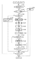
図4は本実施の形態の撮像装置100の主ルーチンのフローチャートを示す。   FIG. 4 shows a flowchart of the main routine of the imaging apparatus 100 of the present embodiment.

図4において、メインスイッチ72によるON操作や電池交換等の電源投入により、システム制御回路50はフラグや制御変数等を初期化すると共に、撮像装置100各部の初期化処理を行う(ステップS101)。   In FIG. 4, the system control circuit 50 initializes flags, control variables, and the like and initializes each part of the imaging apparatus 100 by turning on the main switch 72 and turning on power such as battery replacement (step S101).

次に、システム制御回路50はメインスイッチ72の状態を確認する(ステップS102)。電源OFFに設定されていたならば、各表示部の表示を終了状態に変更し、バリア102を閉じて撮像部を保護し、フラグや制御変数等を含む必要なパラメータや設定値、設定モードを不揮発性メモリ56に記録する。更に、システム制御回路50は、電源制御部80により画像表示部28を含む撮像装置100各部の不要な電源を遮断する等の所定の終了処理を行った後(ステップS103)、ステップS102に戻る。   Next, the system control circuit 50 checks the state of the main switch 72 (step S102). If the power has been set to OFF, the display of each display unit is changed to the end state, the barrier 102 is closed to protect the imaging unit, and necessary parameters, setting values, and setting modes including flags and control variables are set. Record in the nonvolatile memory 56. Further, the system control circuit 50 performs a predetermined end process such as shutting off unnecessary power of each part of the imaging apparatus 100 including the image display unit 28 by the power control unit 80 (step S103), and then returns to step S102.

ステップS102でメインスイッチ72が電源ONに設定されていたならば、ステップS104に進む。ステップS104において、システム制御回路50は、電源制御部80により電池等により構成される電源86の残容量や動作情況が撮像装置100の動作に問題があるか否かを判断する。問題があるならば(ステップS104でNO)、通知部54や画像表示部28を用いて画像や音声により所定の警告を行った後に(ステップS105)、上述したステップS103の処理を行い、ステップS102に戻る。   If the main switch 72 is set to ON in step S102, the process proceeds to step S104. In step S <b> 104, the system control circuit 50 determines whether there is a problem in the operation of the imaging apparatus 100 due to the remaining capacity and operation status of the power supply 86 configured by a battery or the like by the power supply control unit 80. If there is a problem (NO in step S104), after giving a predetermined warning by an image or sound using the notification unit 54 or the image display unit 28 (step S105), the process of step S103 described above is performed, and step S102 is performed. Return to.

一方、電源86に問題が無いならば(ステップS104でYES)、ステップS106に進む。そして、システム制御回路50は、通知部54及び或いは画像表示部28を用いて画像や音声により電池残容量やメモリ30の状態を含む撮像装置100の各種設定状態の表示を行い、ステップS107に進む。   On the other hand, if there is no problem with the power supply 86 (YES in step S104), the process proceeds to step S106. Then, the system control circuit 50 uses the notification unit 54 and / or the image display unit 28 to display various setting states of the imaging device 100 including the remaining battery capacity and the state of the memory 30 using images and sounds, and proceeds to step S107. .

ステップS107において、システム制御回路50は、操作部70に含まれる接続先の登録(ペアリング)ボタンが押されているかどうかを判断する。押されていれば、システム制御回路50は、通信回路110、アンテナ112、アンテナ332、通信回路330を介して、画像処理装置300との間で接続先の登録処理を実行し(ステップS108)、押されていないならばステップS109に進む。   In step S <b> 107, the system control circuit 50 determines whether the connection destination registration (pairing) button included in the operation unit 70 is pressed. If pressed, the system control circuit 50 executes connection destination registration processing with the image processing apparatus 300 via the communication circuit 110, the antenna 112, the antenna 332, and the communication circuit 330 (step S108). If not, the process proceeds to step S109.

接続先の登録処理(ステップS108)においては、撮像装置100が画像処理装置300等の無線機能を備える機器と無線接続するために必要な接続相手の無線パラメータを事前に取得する。そして、取得した無線パラメータを撮像装置100内部のシステム制御回路50の内部メモリ及び或いはメモリ52及び或いは不揮発性メモリ56に記憶する。無線パラメータの取得に際しては、記録媒体200を介して情報のやりとりをすることが可能である。また、US等の有線インターフェースにより、撮像装置100と画像処理装置300をケーブルを用いて接続し、無線パラメータの取得のやりとりを行うことも可能である。記憶した無線パラメータは、撮像装置100が、画像処理装置300等の無線機能を備える機器と無線接続を行う場合に使用する。接続先の登録処理を終えたならば、ステップS102に戻る。 In the connection destination registration process (step S108), the wireless parameter of the connection partner necessary for the imaging apparatus 100 to wirelessly connect to a device having a wireless function such as the image processing apparatus 300 is acquired in advance. The acquired wireless parameters are stored in the internal memory of the system control circuit 50 in the imaging apparatus 100 and / or the memory 52 and / or the nonvolatile memory 56. When acquiring the wireless parameters, information can be exchanged via the recording medium 200. Further, the wired interface, such as US B, an imaging apparatus 100 and the image processing apparatus 300 is connected with a cable, it is possible to perform acquisition of the exchange of radio parameters. The stored wireless parameters are used when the imaging apparatus 100 makes a wireless connection with a device having a wireless function such as the image processing apparatus 300. When the connection destination registration process is completed, the process returns to step S102.

ステップS109において、システム制御回路50は、無線接続を開始するために、操作部70に含まれる通信開始ボタンが押されているか否かを判断する。押されていればステップS114に進み、押されていなければ、ステップS110に進んでシステム制御回路50は、無線接続を行わずに撮像装置100の各種動作を実行する。なお、ステップS110で行う処理は、従来の撮像装置で行われる処理と同様であるため、ここでは説明を省略する。各種動作を終了すると、ステップS102に戻る。   In step S109, the system control circuit 50 determines whether or not the communication start button included in the operation unit 70 is pressed in order to start the wireless connection. If the button is pressed, the process proceeds to step S114. If the button is not pressed, the process proceeds to step S110, and the system control circuit 50 executes various operations of the imaging apparatus 100 without performing wireless connection. Note that the processing performed in step S110 is the same as the processing performed in the conventional imaging apparatus, and thus description thereof is omitted here. When the various operations are completed, the process returns to step S102.

一方、ステップS114において、システム制御回路50は、モードダイアルスイッチ60の設定状態を判断する。動画撮影モードに設定されていたならば、システム制御回路50は、通知部54及び或いは画像表示部28を用いて画像や音声により所定の警告を行い(ステップS115)、ステップS102に戻る。この処理は、以下の理由による。即ち、通信回路110、アンテナ112、アンテナ332、通信回路330を介して撮像装置100から画像処理装置300に撮影中の動画を無線伝送するには伝送レートが不足することがある。そのため、動画撮影モードで無線接続を行おうとした時に所定の警告を行う。このように制御することにより、動画転送できないにも関わらず撮像装置100の使用者が誤って動画モードで無線接続を行い、動画撮影を行うことを防止することができる。これにより、フレーム落ちしたり、途中で打ち切られたり、或いは一時停止したりする不完全な動画データの転送を行うことを防止することができる。   On the other hand, in step S <b> 114, the system control circuit 50 determines the setting state of the mode dial switch 60. If the moving image shooting mode has been set, the system control circuit 50 issues a predetermined warning by an image or sound using the notification unit 54 and / or the image display unit 28 (step S115), and returns to step S102. This process is for the following reason. That is, the transmission rate may be insufficient to wirelessly transmit a moving image being shot from the imaging apparatus 100 to the image processing apparatus 300 via the communication circuit 110, the antenna 112, the antenna 332, and the communication circuit 330. Therefore, a predetermined warning is given when trying to establish a wireless connection in the moving image shooting mode. By controlling in this way, it is possible to prevent the user of the imaging apparatus 100 from erroneously making a wireless connection in the moving image mode and performing moving image shooting even though the moving image cannot be transferred. As a result, it is possible to prevent incomplete moving image data from being transferred, such as dropping frames, being interrupted, or being temporarily stopped.

一方、モードダイヤルスイッチ60が静止画撮影モード或いは再生モードに設定されていたならば(ステップS114でNO)、以下の動作を行う。即ち、システム制御回路50は、通信回路110、アンテナ112、アンテナ332、通信回路330を介して、画像処理装置300との間の通信状態を確立するための接続確立処理を行う(ステップS116)。接続確立処理を実行した結果、撮像装置100と画像処理装置300との間で通信が確立しなかったならば(ステップS117でNO)、ステップS118に進む。そして、システム制御回路50は、通知部54及び或いは画像表示部28を用いて画像や音声により所定の警告を行った後、ステップS125に進む。   On the other hand, if the mode dial switch 60 is set to the still image shooting mode or the playback mode (NO in step S114), the following operation is performed. That is, the system control circuit 50 performs a connection establishment process for establishing a communication state with the image processing apparatus 300 via the communication circuit 110, the antenna 112, the antenna 332, and the communication circuit 330 (step S116). If communication is not established between the imaging apparatus 100 and the image processing apparatus 300 as a result of executing the connection establishment process (NO in step S117), the process proceeds to step S118. Then, the system control circuit 50 issues a predetermined warning by an image or sound using the notification unit 54 and / or the image display unit 28, and then proceeds to step S125.

接続確立処理を実行した結果、撮像装置100と画像処理装置300との間で通信が確立したならば(ステップS117でYES)、システム制御回路50は、モードダイアルスイッチ60の設定状態を判断する(ステップS119)。   If communication is established between the imaging device 100 and the image processing device 300 as a result of executing the connection establishment processing (YES in step S117), the system control circuit 50 determines the setting state of the mode dial switch 60 ( Step S119).

モードダイアルスイッチ60が静止画撮影モードに設定されていたならば(ステップS119でYES)、以下の処理を行う。即ち、システム制御回路50は、通信回路110、アンテナ112、アンテナ332、通信回路330を介して、画像処理装置300に動作モードが静止画撮影モードであることを通知し、撮影同時転送処理(ステップS120)を実行する。なお、この撮影同時転送処理(ステップS120)の詳細は、図5及び図6を用いて後述する。   If the mode dial switch 60 is set to the still image shooting mode (YES in step S119), the following processing is performed. That is, the system control circuit 50 notifies the image processing apparatus 300 that the operation mode is the still image shooting mode via the communication circuit 110, the antenna 112, the antenna 332, and the communication circuit 330, and performs the simultaneous shooting transfer process (step S120) is executed. The details of the simultaneous photographing transfer process (step S120) will be described later with reference to FIGS.

撮影同時転送処理を終えたならば、ステップS125に進む。   If the simultaneous photographing transfer process is completed, the process proceeds to step S125.

一方、モードダイアルスイッチ60が再生モードに設定されていたならば(ステップS119でNO)、以下の処理を行う。即ち、システム制御回路50は、通信回路110、アンテナ112、アンテナ332、通信回路330を介して、画像処理装置300に動作モードが再生モードであることを通知する。そして、画像処理装置300にPC制御モードの問い合わせを行う(ステップS121)。   On the other hand, if the mode dial switch 60 is set to the reproduction mode (NO in step S119), the following processing is performed. That is, the system control circuit 50 notifies the image processing apparatus 300 that the operation mode is the reproduction mode via the communication circuit 110, the antenna 112, the antenna 332, and the communication circuit 330. Then, an inquiry about the PC control mode is made to the image processing apparatus 300 (step S121).

問い合わせの結果、画像処理装置300において、PCダイレクト転送モード(DT)が選択されていたならば(ステップS122でDT)、システム制御回路50は、PCダイレクト転送処理(ステップS123)を実行する。なお、このPCダイレクト転送処理(ステップS123)の詳細は、図7を用いて後述する。   As a result of the inquiry, if the PC direct transfer mode (DT) is selected in the image processing apparatus 300 (DT in step S122), the system control circuit 50 executes PC direct transfer processing (step S123). Details of the PC direct transfer process (step S123) will be described later with reference to FIG.

PCダイレクト転送処理を終えたならば、ステップS125に進む。   If the PC direct transfer process is completed, the process proceeds to step S125.

ステップS121の問い合わせの結果、画像処理装置300において、リモートキャプチャーモード(RC)が選択されていたならば(ステップS122でRC)、システム制御回路50は、リモートキャプチャー処理(ステップS124)を実行する。なお、このリモートキャプチャー処理(ステップS124)の詳細は、図8を用いて後述する。   As a result of the inquiry in step S121, if the remote capture mode (RC) is selected in the image processing apparatus 300 (RC in step S122), the system control circuit 50 executes the remote capture process (step S124). Details of the remote capture process (step S124) will be described later with reference to FIG.

リモートキャプチャー処理を終えたならば、ステップS125に進む。   If the remote capture process is completed, the process proceeds to step S125.

ステップS125において、システム制御回路50は、無線接続を切断するために、操作部70に含まれる通信終了ボタンが押されているか否かを判断する。通信終了ボタンが押されていなければ、ステップS102に戻る。   In step S125, the system control circuit 50 determines whether or not the communication end button included in the operation unit 70 is pressed in order to disconnect the wireless connection. If the communication end button has not been pressed, the process returns to step S102.

通信終了ボタンが押されていたならば、システム制御回路50は、通信回路110、アンテナ112、アンテナ332、通信回路330を介して、画像処理装置300との間の無線を切断する処理を行う(ステップS126)。そして、ステップS102に戻る。   If the communication end button has been pressed, the system control circuit 50 performs a process of disconnecting radio from the image processing apparatus 300 via the communication circuit 110, the antenna 112, the antenna 332, and the communication circuit 330 ( Step S126). Then, the process returns to step S102.

図5及び図6は、図4のステップS120における撮影同時転送処理の詳細を示すフローチャートである。   5 and 6 are flowcharts showing details of the simultaneous photographing transfer process in step S120 of FIG.

ステップS131において、システム制御回路50は、通信回路110、アンテナ112、アンテナ332、通信回路330を介して、画像処理装置300との間の通信状態を確認する。電波の状態が悪くなったり、操作部70に含まれる通信終了ボタンの押下などの理由により確立していた接続が切断され、画像処理装置300との無線接続がされていなかったならば、ステップS132に進む。そして、システム制御回路50は、通知部54及び/或いは画像表示部28を用いて画像や音声により所定の警告を行ってから、撮影同時転送処理ルーチン(ステップS120)を終了する。   In step S <b> 131, the system control circuit 50 confirms a communication state with the image processing apparatus 300 via the communication circuit 110, the antenna 112, the antenna 332, and the communication circuit 330. If the connection established for a reason such as the deterioration of the radio wave state or the depression of the communication end button included in the operation unit 70 is disconnected and the wireless connection with the image processing apparatus 300 is not established, step S132 is performed. Proceed to The system control circuit 50 issues a predetermined warning by an image or sound using the notification unit 54 and / or the image display unit 28, and then ends the simultaneous photographing transfer processing routine (step S120).

画像処理装置300との無線接続がされていればステップS133に進み、シャッタースイッチSW1の状態を確認する。シャッタースイッチSW1が押されていなければ、撮影同時転送処理ルーチン(ステップS120)を終了する。   If the wireless connection with the image processing apparatus 300 is established, the process proceeds to step S133, and the state of the shutter switch SW1 is confirmed. If the shutter switch SW1 is not pressed, the photographing simultaneous transfer processing routine (step S120) is terminated.

シャッタースイッチSW1が押されたならば(ステップS133でON)、メモリ30に確保したバッファ領域に、少なくとも1枚分の画像データを記憶する容量が残されているかどうかを判断する(ステップS134)。空き容量が無ければ、システム制御回路50は、表示部54及び或いは画像表示部28を用いて画像や音声により所定の警告を行う(ステップS137)。そして、メモリ30に確保したバッファ領域から通信回路110、アンテナ112を介して画像処理装置300に向けて未転送画像データの転送を開始し(ステップS138)、撮影同時転送処理ルーチン(ステップS120)を終了する。なお、OVF撮影状態においては画像表示部28がOFFに設定されているため、画像表示部28をONにしてから画像表示部28に文字やアイコンや画像による所定の警告を行うことになる。   If the shutter switch SW1 is pressed (ON in step S133), it is determined whether or not a capacity for storing at least one image data is left in the buffer area secured in the memory 30 (step S134). If there is no free space, the system control circuit 50 issues a predetermined warning by an image or sound using the display unit 54 and / or the image display unit 28 (step S137). Then, transfer of untransferred image data is started from the buffer area secured in the memory 30 to the image processing apparatus 300 via the communication circuit 110 and the antenna 112 (step S138), and a photographing simultaneous transfer processing routine (step S120) is executed. finish. Since the image display unit 28 is set to OFF in the OVF shooting state, a predetermined warning by characters, icons, or images is given to the image display unit 28 after the image display unit 28 is turned on.

メモリ30に確保したバッファ領域に空き容量があれば、記録媒体200が装着されているかどうかの判断、記録媒体200に記録された画像データの管理情報の取得をする。更に、記録媒体200の動作状態が撮像装置100の動作、特に記録媒体に対する画像データの記録再生動作に問題があるか否かの判断を行う(ステップS135)。問題が無いならばステップS139に進む。   If there is free space in the buffer area secured in the memory 30, it is determined whether or not the recording medium 200 is loaded, and management information of image data recorded on the recording medium 200 is acquired. Further, it is determined whether or not the operation state of the recording medium 200 has a problem with the operation of the imaging apparatus 100, particularly with respect to the recording / reproducing operation of the image data on the recording medium (step S135). If there is no problem, the process proceeds to step S139.

一方、問題があるならば、ステップS136に進み、システム制御回路50は、メモリ30に確保したバッファ領域に、撮像装置100から画像処理装置300に向けて未転送の画像データが有るかどうかを判断する。未転送画像データが無いならば(ステップS136でNO)、ステップS139に進む。   On the other hand, if there is a problem, the process proceeds to step S136, and the system control circuit 50 determines whether there is untransferred image data from the imaging apparatus 100 to the image processing apparatus 300 in the buffer area secured in the memory 30. To do. If there is no untransferred image data (NO in step S136), the process proceeds to step S139.

未転送画像データがあるならば(ステップS136でYES)、ステップS137で上述した警告を行ってから、ステップS138で未転送画像データの転送を開始し、撮影同時転送処理ルーチン(ステップS120)を終了する。なお、OVF撮影状態においては画像表示部28がOFFに設定されているため、画像表示部28をONにしてから画像表示部28に文字やアイコンや画像による所定の警告を行うことになる。   If there is untransferred image data (YES in step S136), the warning described above is given in step S137, transfer of untransferred image data is started in step S138, and the photographing simultaneous transfer processing routine (step S120) is ended. To do. Since the image display unit 28 is set to OFF in the OVF shooting state, a predetermined warning by characters, icons, or images is given to the image display unit 28 after the image display unit 28 is turned on.

以上のように、画像処理装置300との間で無線接続状態であり、かつ、記録媒体200が使用できない状態であり、かつ、メモリ30に確保したバッファー領域に画像処理装置300に未転送の画像があったならば、撮影を禁止して警告を行う。そして、未転送画像を画像処理装置300に転送する。このように、記録媒体200が使用できない場合には、前回までに撮影した画像の転送が終了するまでは撮影を禁止する。これにより、撮影した画像の保存が不確実であるにも関わらず、撮像装置100の使用者が、撮影した画像が全て確実に保存できると勘違いして、撮影を継続してしまうことを防止することができる。   As described above, an image that is wirelessly connected to the image processing apparatus 300 and that the recording medium 200 cannot be used, and an image that has not been transferred to the image processing apparatus 300 in the buffer area secured in the memory 30. If there is a warning, prohibit shooting and give a warning. Then, the untransferred image is transferred to the image processing apparatus 300. As described above, when the recording medium 200 cannot be used, photographing is prohibited until the transfer of the images photographed up to the previous time is completed. This prevents the user of the imaging apparatus 100 from mistakenly assuming that all of the captured images can be reliably stored despite the uncertain storage of the captured images and continuing the shooting. be able to.

ステップS139において、システム制御回路50は、測距処理を行って撮影レンズ10の焦点を被写体に合わせ、測光処理を行って絞り値及びシャッタ時間を決定し、ホワイトバランス処理を行って色温度を合わせる。測光の結果、必要であればフラッシュの設定も行う。なお、この測距・測光処理では、システム制御回路50の内部メモリ或いはメモリ52に記憶された撮影開始フラグ及び/或いはAEロックフラグ及び/或いはホワイトバランスモード設定フラグを確認する。そして、その状態に応じて、AE制御及び/或いはAWB制御の実行の可否を判断し、判断結果に応じて各々の処理を行う。なお、ここで行われる測距・測光処理の詳細は、図9を参照して後述する。   In step S139, the system control circuit 50 performs a distance measurement process to focus the photographing lens 10 on the subject, performs a photometry process to determine an aperture value and a shutter time, performs a white balance process, and adjusts the color temperature. . As a result of photometry, the flash is set if necessary. In this distance measurement / photometry process, the photographing start flag and / or AE lock flag and / or white balance mode setting flag stored in the internal memory of the system control circuit 50 or the memory 52 are confirmed. Then, according to the state, it is determined whether or not the AE control and / or the AWB control can be executed, and each process is performed according to the determination result. Details of the distance measurement / photometry processing performed here will be described later with reference to FIG.

測距・測光処理(ステップS139)を終えたならば、システム制御回路50は、システム制御回路50の内部メモリ或いはメモリ52に記憶されたフラッシュフラグの状態を判断する(ステップS140)。フラッシュフラグが設定されていたならば、フラッシュ48の充電を行い(ステップS141)、ステップS142に進む。フラッシュフラグが解除されていたならば、直接ステップS142に進む。   After completing the distance measurement / photometry processing (step S139), the system control circuit 50 determines the state of the flash flag stored in the internal memory of the system control circuit 50 or the memory 52 (step S140). If the flash flag has been set, the flash 48 is charged (step S141), and the process proceeds to step S142. If the flash flag has been canceled, the process proceeds directly to step S142.

システム制御回路50は、シャッタースイッチSW2が押されずに(ステップS142でOFF)、更にシャッタースイッチSW1も解除されたならば(ステップS143でOFF)、撮影同時転送処理ルーチン(ステップS120)を終了する。シャッタースイッチSW1が押されたままであったならば(ステップS143でON)、再びステップS142に戻る。   If the shutter switch SW2 is not pressed (OFF in step S142) and the shutter switch SW1 is also released (OFF in step S143), the system control circuit 50 ends the photographing simultaneous transfer processing routine (step S120). If the shutter switch SW1 remains pressed (ON in step S143), the process returns to step S142 again.

シャッタースイッチSW2が押されたならば(ステップS142でON)、メモリ30に確保したバッファ領域に、少なくとも1枚分の画像データを記憶する容量が残されているかどうかを判断する(ステップS144)。空き容量が無ければ、システム制御回路50は、表示部54及び或いは画像表示部28を用いて画像や音声により所定の警告を行う(ステップS147)。そして、メモリ30に確保したバッファ領域から通信回路110、アンテナ112を介して画像処理装置300に向けて未転送画像データの転送を開始し(ステップS148)、撮影同時転送処理ルーチン(ステップS120)を終了する。なお、OVF撮影状態においては画像表示部28がOFFに設定されているため、画像表示部28をONにしてから画像表示部28に文字やアイコンや画像による所定の警告を行うことになる。   If the shutter switch SW2 is pressed (ON in step S142), it is determined whether or not a capacity for storing at least one image data is left in the buffer area secured in the memory 30 (step S144). If there is no free space, the system control circuit 50 issues a predetermined warning by an image or sound using the display unit 54 and / or the image display unit 28 (step S147). Then, transfer of untransferred image data is started from the buffer area secured in the memory 30 to the image processing apparatus 300 via the communication circuit 110 and the antenna 112 (step S148), and a photographing simultaneous transfer processing routine (step S120) is executed. finish. Since the image display unit 28 is set to OFF in the OVF shooting state, a predetermined warning by characters, icons, or images is given to the image display unit 28 after the image display unit 28 is turned on.

メモリ30に確保したバッファ領域に空き容量があれば、記録媒体200が装着されているかどうかの判断、記録媒体200に記録された画像データの管理情報の取得をする。更に、記録媒体200の動作状態が撮像装置100の動作、特に記録媒体に対する画像データの記録再生動作に問題があるか否かの判断を行う(ステップS145)。問題がなければ、図6のステップS151に進む。   If there is free space in the buffer area secured in the memory 30, it is determined whether or not the recording medium 200 is loaded, and management information of image data recorded on the recording medium 200 is acquired. Further, it is determined whether or not the operation state of the recording medium 200 has a problem in the operation of the imaging apparatus 100, particularly in the recording / reproducing operation of the image data with respect to the recording medium (step S145). If there is no problem, the process proceeds to step S151 in FIG.

一方、問題があるならば、ステップS146に進み、システム制御回路50は、メモリ30に確保したバッファ領域に、撮像装置100から画像処理装置300に向けて未転送の画像データが有るかどうかを判断する。未転送画像データが無いならば(ステップS146でNO)、図6のステップS151に進む。   On the other hand, if there is a problem, the process proceeds to step S146, and the system control circuit 50 determines whether there is untransferred image data from the imaging apparatus 100 to the image processing apparatus 300 in the buffer area secured in the memory 30. To do. If there is no untransferred image data (NO in step S146), the process proceeds to step S151 in FIG.

未転送画像データがあるならば(ステップS146でYES)、ステップS147で上述した警告を行ってから、ステップS148で未転送画像データの転送を開始し、撮影同時転送処理ルーチン(ステップS120)を終了する。なお、OVF撮影状態においては画像表示部28がOFFに設定されているため、画像表示部28をONにしてから画像表示部28に文字やアイコンや画像による所定の警告を行うことになる。   If there is untransferred image data (YES in step S146), the warning described above is performed in step S147, transfer of untransferred image data is started in step S148, and the photographing simultaneous transfer processing routine (step S120) is ended. To do. Since the image display unit 28 is set to OFF in the OVF shooting state, a predetermined warning by characters, icons, or images is given to the image display unit 28 after the image display unit 28 is turned on.

以上のように、画像処理装置300との間で無線接続状態であり、かつ、記録媒体200が使用できない状態であり、かつ、メモリ30に確保したバッファー領域に画像処理装置300に未転送の画像があったならば、撮影を禁止して警告を行う。そして、未転送画像を画像処理装置300に転送する。このように、記録媒体200が使用できない場合には、撮像装置100の使用者がシャッタースイッチSW2(64)を押した場合であっても、前回までに撮影した画像の転送が終了するまでは撮影を禁止する。これにより、画像の保存が不確実な場合に撮影を行わないようにするとともに、撮像装置100の使用者が、撮影した画像が全て確実に保存できると勘違いして、撮影を継続してしまうことを防止することができる。   As described above, an image that is wirelessly connected to the image processing apparatus 300 and that the recording medium 200 cannot be used, and an image that has not been transferred to the image processing apparatus 300 in the buffer area secured in the memory 30. If there is a warning, prohibit shooting and give a warning. Then, the untransferred image is transferred to the image processing apparatus 300. As described above, when the recording medium 200 cannot be used, even when the user of the imaging apparatus 100 presses the shutter switch SW2 (64), the shooting is performed until the transfer of the previously captured image is completed. Is prohibited. As a result, shooting is not performed when image storage is uncertain, and the user of the imaging apparatus 100 misunderstands that all captured images can be stored reliably, and continues shooting. Can be prevented.

図6のステップS151において、システム制御回路50は撮影処理を実行する。この撮影処理では、撮像素子14、A/D変換器16、画像処理回路20、メモリ制御回路22を介して、或いはA/D変換器から直接メモリ制御回路22を介して、メモリ30に撮影した画像データを書き込む。なお、ここで行われる撮影処理の詳細は、図10を参照して後述する。   In step S151 in FIG. 6, the system control circuit 50 executes a photographing process. In this photographing process, the image is taken in the memory 30 via the image sensor 14, the A / D converter 16, the image processing circuit 20, the memory control circuit 22, or directly from the A / D converter via the memory control circuit 22. Write image data. The details of the photographing process performed here will be described later with reference to FIG.

次に、システム制御回路50は、メモリ制御回路22そして必要に応じて画像処理回路20を用いて、メモリ30に書き込まれた画像データを読み出して各種処理を行う現像処理を実行する(ステップS152)。更に、必要に応じて、圧縮・伸長回路32を用いて設定したモードに応じた画像圧縮処理を行った後(ステップS153)、画像表示部28によりステップS152で現像処理を行った撮影画像のレビュー表示を行う(ステップS154)。そして、ステップS155に進む。   Next, the system control circuit 50 uses the memory control circuit 22 and, if necessary, the image processing circuit 20 to execute development processing for reading the image data written in the memory 30 and performing various processes (step S152). . Furthermore, if necessary, after performing image compression processing corresponding to the mode set using the compression / decompression circuit 32 (step S153), the image display unit 28 reviews the photographed image that has been developed in step S152. Display is performed (step S154). Then, the process proceeds to step S155.

ステップS155において、システム制御回路50は、システム制御回路50は、記録媒体200が装着されているかどうかの判断、記録媒体200に記録された画像データの管理情報の取得をする。更に、記録媒体200の動作状態が撮像装置100の動作、特に記録媒体200に対する画像データの記録再生動作に問題があるか否かの判断を行う。   In step S <b> 155, the system control circuit 50 determines whether or not the recording medium 200 is loaded, and acquires management information of image data recorded on the recording medium 200. Further, it is determined whether or not the operation state of the recording medium 200 has a problem in the operation of the imaging apparatus 100, particularly in the recording / reproducing operation of the image data with respect to the recording medium 200.

記録媒体200の動作状態に問題が無いならば(ステップS155でYES)、メモリ30に確保したバッファ領域に、現像処理、圧縮処理等の所定の処理を行った画像データを記憶する(ステップS158)。更に、バッファ領域に記憶した画像データを、インターフェース90、コネクタ92を介して、記録媒体200に記録し、ステップS161に進む。   If there is no problem in the operation state of the recording medium 200 (YES in step S155), image data that has undergone predetermined processing such as development processing and compression processing is stored in the buffer area secured in the memory 30 (step S158). . Further, the image data stored in the buffer area is recorded on the recording medium 200 via the interface 90 and the connector 92, and the process proceeds to step S161.

一方、判断の結果、記録媒体200の動作状態に問題があるならば(ステップS155でNO)、ステップS156に進む。ステップS156では、システム制御回路50は、メモリ30に確保したバッファ領域に、撮像装置100から画像処理装置300に向けて未転送の画像データが有るかどうかを判断する。未転送画像データが無いならば(ステップS156でNO)、バッファに撮影した画像データを記憶し(ステップS159)、ステップS161に進む。   On the other hand, as a result of the determination, if there is a problem in the operation state of the recording medium 200 (NO in step S155), the process proceeds to step S156. In step S <b> 156, the system control circuit 50 determines whether there is untransferred image data from the imaging apparatus 100 to the image processing apparatus 300 in the buffer area secured in the memory 30. If there is no untransferred image data (NO in step S156), the captured image data is stored in the buffer (step S159), and the process proceeds to step S161.

ステップS161では、バッファ領域に記憶されている画像データの転送を開始する。   In step S161, transfer of image data stored in the buffer area is started.

一方、未転送画像データがあるならば(ステップS156でYES)、システム制御回路50は、表示部54及び或いは画像表示部28を用いて画像や音声により所定の警告を行い(ステップS157)、ステップS161に進む。この場合、ステップS151で新たに撮影された画像データはバッファに記憶されないので、ステップS161ではバッファに残ってる未転送の画像データの転送を開始し、撮影同時転送処理ルーチン(ステップS120)を終了する。なお、OVF撮影状態においては画像表示部28がOFFに設定されているため、画像表示部28をONにしてから画像表示部28に文字やアイコンや画像による所定の警告を行うことになる。   On the other hand, if there is untransferred image data (YES in step S156), the system control circuit 50 issues a predetermined warning by image or sound using the display unit 54 and / or the image display unit 28 (step S157), The process proceeds to S161. In this case, since the image data newly photographed in step S151 is not stored in the buffer, transfer of untransferred image data remaining in the buffer is started in step S161, and the photographing simultaneous transfer processing routine (step S120) is ended. . Since the image display unit 28 is set to OFF in the OVF shooting state, a predetermined warning by characters, icons, or images is given to the image display unit 28 after the image display unit 28 is turned on.

以上のように、画像処理装置300との間で無線接続状態であり、かつ、記録媒体200が使用できない状態であり、かつ、メモリ30に確保したバッファ領域に画像処理装置300に未転送の画像があったならば、以下のように制御する。即ち、空撮り撮影を行った後に、レビュー表示を行い、更に警告を行う。このように、記録媒体200が使用できない場合には、撮像後であっても、前回までに撮影した画像の転送が終了するまではバッファへの記憶を禁止する。これにより、画像の転送が不確実な場合に撮影した画像の記憶を行わないようにするとともに、撮像装置100の使用者が、撮影した画像が全て確実に保存できると勘違いして、撮影を継続してしまうことを防止することができる。   As described above, the image is wirelessly connected to the image processing apparatus 300 and the recording medium 200 cannot be used, and the image that has not been transferred to the image processing apparatus 300 in the buffer area secured in the memory 30. If there is, control as follows. In other words, after taking a sky shot, a review is displayed and a warning is given. As described above, when the recording medium 200 cannot be used, storage in the buffer is prohibited until the transfer of the image captured up to the previous time is completed even after imaging. As a result, when the transfer of the image is uncertain, the captured image is not stored, and the user of the imaging apparatus 100 misunderstands that all the captured images can be reliably stored, so that the shooting is continued. Can be prevented.

次に、ステップS162において、システム制御回路50は、シャッタースイッチSW1の状態を確認し、シャッタースイッチSW1が押されていたならば、ステップS131に戻る。シャッタースイッチSW1が押されていないならば、撮影同時転送処理ルーチン(ステップS120)を終了する。   Next, in step S162, the system control circuit 50 confirms the state of the shutter switch SW1, and if the shutter switch SW1 has been pressed, returns to step S131. If the shutter switch SW1 is not pressed, the photographing simultaneous transfer processing routine (step S120) is terminated.

図7は、図4のステップS123におけるPCダイレクト転送処理の詳細なフローチャートを示す。   FIG. 7 shows a detailed flowchart of the PC direct transfer process in step S123 of FIG.

ステップ123において、システム制御回路50は、通信回路110、アンテナ112、アンテナ332、通信回路330を介して、画像処理装置300との間の通信状態を確認する。電波の状態が悪くなったり、操作部70に含まれる通信終了ボタンの押下などの理由により確立していた接続が切断され、画像処理装置300との無線接続がされていなかったならば、ステップS172に進む。そして、システム制御回路50は、通知部54及び/或いは画像表示部28を用いて画像や音声により所定の警告を行ってから、PCダイレクト転送処理ルーチン(ステップS123)を終了する。   In step 123, the system control circuit 50 confirms the communication state with the image processing apparatus 300 via the communication circuit 110, the antenna 112, the antenna 332, and the communication circuit 330. If the connection established for a reason such as the deterioration of the radio wave state or the depression of the communication end button included in the operation unit 70 is disconnected and the wireless connection with the image processing apparatus 300 is not established, step S172 is performed. Proceed to The system control circuit 50 issues a predetermined warning by an image or sound using the notification unit 54 and / or the image display unit 28, and then ends the PC direct transfer processing routine (step S123).

画像処理装置300との無線接続がされているならば、ステップS173に進む。   If a wireless connection with the image processing apparatus 300 is established, the process proceeds to step S173.

ステップS173において、システム制御回路50は、記録媒体200及び/或いはメモリ30に確保したバッファ領域に、撮像装置100から画像処理装置300に向けて転送する画像データ等のファイルが有るかどうかを判断する。転送する画像データ等のファイルが無いならば、PCダイレクト転送処理ルーチン(ステップS123)を終了する。一方、転送する画像データ等のファイルがあるならば、ステップS174に進む。   In step S <b> 173, the system control circuit 50 determines whether a file such as image data to be transferred from the imaging apparatus 100 to the image processing apparatus 300 exists in the buffer area secured in the recording medium 200 and / or the memory 30. . If there is no file such as image data to be transferred, the PC direct transfer processing routine (step S123) is terminated. On the other hand, if there is a file such as image data to be transferred, the process proceeds to step S174.

ステップS174において、システム制御回路50は、記録媒体200及び/或いは、メモリ30に確保したバッファ領域から画像処理装置300に向けて転送すべき画像データ等のファイルの転送を行い、ステップS175に進む。記録媒体200からは、コネクタ92、インターフェース90、通信回路110、アンテナ112を介して、また、メモリ30のバッファ領域からは通信回路110、アンテナ112を介して、ファイルが転送される。   In step S174, the system control circuit 50 transfers a file such as image data to be transferred to the image processing apparatus 300 from the buffer area secured in the recording medium 200 and / or the memory 30, and the process proceeds to step S175. Files are transferred from the recording medium 200 via the connector 92, the interface 90, the communication circuit 110, and the antenna 112, and from the buffer area of the memory 30 via the communication circuit 110 and the antenna 112.

転送が終了するまで(即ち、ステップS175でNOの間)、ステップS174に戻って転送を続け、終了したならば(ステップS175でYES)、PCダイレクト転送処理ルーチン(ステップS120)を終了する。   Until the transfer ends (that is, during NO in step S175), the process returns to step S174 to continue the transfer. If the transfer ends (YES in step S175), the PC direct transfer processing routine (step S120) ends.

図8は、図4のステップS124におけるリモートキャプチャー処理の詳細なフローチャートを示す。   FIG. 8 shows a detailed flowchart of the remote capture process in step S124 of FIG.

ステップS181において、システム制御回路50は、通信回路110、アンテナ112、アンテナ332、通信回路330を介して、画像処理装置300との間の通信状態を確認する。電波の状態が悪くなったり、操作部70に含まれる通信終了ボタンの押下などの理由により確立していた接続が切断され、画像処理装置300との無線接続がされていなかったならば、ステップS182に進む。そして、システム制御回路50は、通知部54及び/或いは画像表示部28を用いて画像や音声により所定の警告を行ってから、リモートキャプチャー処理ルーチン(ステップS124)を終了する。   In step S <b> 181, the system control circuit 50 confirms a communication state with the image processing apparatus 300 via the communication circuit 110, the antenna 112, the antenna 332, and the communication circuit 330. If the connection established for a reason such as the deterioration of the radio wave state or the depression of the communication end button included in the operation unit 70 is disconnected and the wireless connection with the image processing apparatus 300 is not established, step S182 is performed. Proceed to Then, the system control circuit 50 gives a predetermined warning by an image or sound using the notification unit 54 and / or the image display unit 28, and then ends the remote capture processing routine (step S124).

画像処理装置300との無線接続がされていればステップS183に進み、システム制御回路50は、通信回路330、アンテナ332、アンテナ112、通信回路110を介して、画像処理装置300からコマンドを受信したかどうかを判断する。   If the wireless connection with the image processing apparatus 300 is established, the process proceeds to step S183, and the system control circuit 50 receives a command from the image processing apparatus 300 via the communication circuit 330, the antenna 332, the antenna 112, and the communication circuit 110. Determine whether or not.

画像処理装置300からコマンドを受信していなかったならば(ステップS183でNO)、ステップS195に進む。画像処理装置300からコマンドを受信したならば(ステップS183でYES)、システム制御回路50はコマンドの内容を判断する。受信したコマンドが撮影に関するコマンド以外であったならば(ステップS184でNO)、システム制御回路50は、コマンドに応じた処理を実行し(ステップS185)、ステップS195に進む。一方、受信したコマンドが撮影コマンドであったならば(ステップS184でYES)、ステップS186に進む。   If a command has not been received from the image processing apparatus 300 (NO in step S183), the process proceeds to step S195. If a command is received from image processing apparatus 300 (YES in step S183), system control circuit 50 determines the content of the command. If the received command is not a command related to shooting (NO in step S184), the system control circuit 50 executes a process corresponding to the command (step S185), and proceeds to step S195. On the other hand, if the received command is a shooting command (YES in step S184), the process proceeds to step S186.

システム制御回路50は、測距処理を行って撮影レンズ10の焦点を被写体に合わせ、測光処理を行って絞り値及びシャッタ時間を決定し、ホワイトバランス処理を行って色温度を合わせる(ステップS186)。測光の結果、必要であればフラッシュの設定も行う。なお、この測距・測光処理では、システム制御回路50の内部メモリ或いはメモリ52に記憶された撮影開始フラグ及び/或いはAEロックフラグ及び/或いはホワイトバランスモード設定フラグを確認する。そして、その状態に応じて、AE制御及び/或いはAWB制御の実行の可否を判断し、判断結果に応じて各々の処理を行う。なお、ここで行われる測距・測光処理の詳細は、図9を参照して後述する。   The system control circuit 50 performs a distance measurement process to focus the photographing lens 10 on the subject, performs a photometry process to determine an aperture value and a shutter time, performs a white balance process, and adjusts the color temperature (step S186). . As a result of photometry, the flash is set if necessary. In this distance measurement / photometry process, the photographing start flag and / or AE lock flag and / or white balance mode setting flag stored in the internal memory of the system control circuit 50 or the memory 52 are confirmed. Then, according to the state, it is determined whether or not the AE control and / or the AWB control can be executed, and each process is performed according to the determination result. Details of the distance measurement / photometry processing performed here will be described later with reference to FIG.

測距・測光処理(ステップS186)を終えたならば、システム制御回路50は、撮影処理を実行する(ステップS187)。この撮影処理では、撮像素子14、A/D変換器16、画像処理回路20、メモリ制御回路22を介して、或いはA/D変換器から直接メモリ制御回路22を介して、メモリ30に撮影した画像データを書き込む。なお、ここで行われる撮影処理の詳細は、図10を参照して後述する。   When the distance measurement / photometry process (step S186) is completed, the system control circuit 50 executes a photographing process (step S187). In this photographing process, the image is taken in the memory 30 via the image sensor 14, the A / D converter 16, the image processing circuit 20, the memory control circuit 22, or directly from the A / D converter via the memory control circuit 22. Write image data. The details of the photographing process performed here will be described later with reference to FIG.

次に、システム制御回路50は、メモリ制御回路22そして必要に応じて画像処理回路20を用いて、メモリ30に書き込まれた画像データを読み出して各種処理を行う現像処理を実行する(ステップS188)。更に、必要に応じて、圧縮・伸長回路32を用いて設定したモードに応じた画像圧縮処理を行った後(ステップS189)、ステップS190に進む。   Next, the system control circuit 50 uses the memory control circuit 22 and, if necessary, the image processing circuit 20 to read out the image data written in the memory 30 and execute development processing for performing various processes (step S188). . Furthermore, if necessary, image compression processing corresponding to the mode set using the compression / decompression circuit 32 is performed (step S189), and then the process proceeds to step S190.

ステップS190において、システム制御回路50は、メモリ30に確保したバッファ領域に、現像処理及び圧縮処理等の所定の処理を行った画像データを記憶して、ステップS191に進む。   In step S190, the system control circuit 50 stores image data that has undergone predetermined processing such as development processing and compression processing in the buffer area secured in the memory 30, and proceeds to step S191.

ステップS191では、システム制御回路50は、記録媒体200が装着されているかどうかの判断を行い、記録媒体200に記録された画像データの管理情報の取得する。そして、記録媒体200の動作状態が撮像装置100の動作、特に記録媒体に対する画像データの記録再生動作に問題があるか否かの判断を行う。問題があるならば、直接ステップS193に進む。問題が無いならば、メモリ30に確保したバッファ領域からインターフェース90、コネクタ92を介して記録媒体200に対して画像データの記録を開始し(ステップS192)、ステップS193に進む。   In step S191, the system control circuit 50 determines whether or not the recording medium 200 is loaded, and acquires management information of image data recorded on the recording medium 200. Then, it is determined whether or not the operation state of the recording medium 200 has a problem in the operation of the imaging apparatus 100, particularly in the recording / reproducing operation of the image data with respect to the recording medium. If there is a problem, the process proceeds directly to step S193. If there is no problem, image data recording is started on the recording medium 200 from the buffer area secured in the memory 30 via the interface 90 and the connector 92 (step S192), and the process proceeds to step S193.

ステップS193では、システム制御回路50は、メモリ30に確保したバッファ領域から通信回路110、アンテナ112を介して画像処理装置300に向けて撮影してバッファに記憶した画像データの転送を行う。画像処理装置300への画像転送が確実に終了したならば(ステップS194でYES)、ステップS195に進む。   In step S193, the system control circuit 50 transfers the image data captured from the buffer area secured in the memory 30 to the image processing apparatus 300 via the communication circuit 110 and the antenna 112 and stored in the buffer. If the image transfer to the image processing apparatus 300 has been completed (YES in step S194), the process proceeds to step S195.

以上のように、画像処理装置300との間で無線接続状態であり、かつ、リモートキャプチャー撮影動作状態であり、かつ、記録媒体200が使用できない状態である場合、以下のように制御する。即ち、画像処理装置300へのリモートキャプチャー静止画の画像1枚の画像転送が完了しないと、新たなリモートキャプチャー静止画の画像撮影を開始できない仕組みとする。リモートキャプチャー撮影時は無線接続での撮影であっても撮影禁止にしないと共に警告も行わないようにすることが可能となり、リモートキャプチャー時の操作性が煩雑になることを防止して使い易くすることが可能となる。   As described above, when the wireless connection state is established with the image processing apparatus 300, the remote capture photographing operation state, and the recording medium 200 cannot be used, the following control is performed. In other words, the image capturing of a new remote capture still image cannot be started unless the image transfer of one remote capture still image to the image processing apparatus 300 is completed. During remote capture shooting, even when shooting wirelessly, it is possible not to prohibit shooting and not to issue warnings, so that the ease of use during remote capture is prevented and it is easy to use Is possible.

システム制御回路50は、撮像装置100側の都合でリモートキャプチャー処理を中断する必要が発生した場合は(ステップS195でYES)、リモートキャプチャー処理ルーチン(ステップS124)を終了する。   When it is necessary to interrupt the remote capture process due to the convenience of the imaging apparatus 100 (YES in step S195), the system control circuit 50 ends the remote capture process routine (step S124).

撮像装置100側の都合でリモートキャプチャー処理を中断する必要が発生していないならば(ステップS195でNO)、ステップS181に戻り、無線接続中であればステップS183において画像処理装置300から新たなコマンドによる指示を待つ。   If it is not necessary to interrupt the remote capture process for the convenience of the imaging apparatus 100 (NO in step S195), the process returns to step S181. If the wireless connection is established, a new command is issued from the image processing apparatus 300 in step S183. Wait for instructions.

図9は、図5のステップS137及び図8のステップS186で行われる測距・測光処理の詳細なフローチャートを示す。   FIG. 9 shows a detailed flowchart of the distance measurement / photometry processing performed in step S137 of FIG. 5 and step S186 of FIG.

システム制御回路50は、撮像素子14から電荷信号を読み出し、A/D変換器16を介して画像処理回路20に画像データを逐次読み込む(ステップS201)。この逐次読み込まれた画像データを用いて、画像処理回路20はTTL方式のAE処理、EF処理、AF処理に用いる所定の演算を行う。
なお、ここでの各処理は、撮影した全画素数のうちの必要に応じた特定の部分を必要個所分切り取って抽出し、演算に用いる。これにより、TTL方式のAE、EF、AWB、AFの各処理において、中央重点モード、平均モード、評価モードの各モード等の異なるモード毎に最適な演算を行うことが可能となる。
The system control circuit 50 reads the charge signal from the image sensor 14 and sequentially reads the image data into the image processing circuit 20 via the A / D converter 16 (step S201). Using the sequentially read image data, the image processing circuit 20 performs predetermined calculations used for TTL AE processing, EF processing, and AF processing.
In each process here, a specific part of the total number of captured pixels is extracted according to necessity and extracted and used for calculation. As a result, in each of the TTL method AE, EF, AWB, and AF processes, it is possible to perform optimum calculation for each different mode such as the center-weighted mode, the average mode, and the evaluation mode.

システム制御回路50は、画像処理回路20での演算結果を用いて露出(AE)が適正と判断されるまで(ステップS202でYESとなるまで)、露光制御部40を用いてAE制御を行う(ステップS203)。そしてステップS204に進み、システム制御回路50は、AE制御で得られた測定データを用いてフラッシュが必要か否かを判断する。フラッシュが必要ならば(ステップS204でYES)フラッシュ・フラグをセットし、フラッシュ48を充電する(ステップS205)。   The system control circuit 50 performs AE control using the exposure control unit 40 until the exposure (AE) is determined to be appropriate using the calculation result in the image processing circuit 20 (until YES in step S202) ( Step S203). In step S204, the system control circuit 50 determines whether or not flashing is necessary using measurement data obtained by AE control. If flash is necessary (YES in step S204), the flash flag is set and the flash 48 is charged (step S205).

露出(AE)が適正と判断したならば(ステップS202でYES)、測定データ及び/或いは設定パラメータをシステム制御回路50の内部メモリ或いはメモリ52に記憶する。   If it is determined that the exposure (AE) is appropriate (YES in step S202), the measurement data and / or setting parameters are stored in the internal memory or the memory 52 of the system control circuit 50.

次に、画像処理回路20での演算結果及びAE制御で得られた測定データを用いて、システム制御回路50はホワイトバランス(AWB)が適正かどうか判断する。適正であると判断されるまで(ステップS206でYESとなるまで)、画像処理回路20を用いて色処理のパラメータを調節してAWB制御を行う(ステップS207)。   Next, the system control circuit 50 determines whether the white balance (AWB) is appropriate using the calculation result in the image processing circuit 20 and the measurement data obtained by the AE control. Until it is determined to be appropriate (until YES in step S206), the image processing circuit 20 is used to adjust color processing parameters and perform AWB control (step S207).

AWBが適正と判断したならば(ステップS206でYES)、測定データ及び/或いは設定パラメータをシステム制御回路50の内部メモリ或いはメモリ52に記憶する。   If it is determined that the AWB is appropriate (YES in step S206), the measurement data and / or setting parameters are stored in the internal memory or the memory 52 of the system control circuit 50.

次に、画像処理回路20での演算結果及びAE制御及びAWB制御で得られた測定データを用いて、システム制御回路50は測距(AF)を行う。そして、その結果が合焦と判断されるまで(ステップS208でNOの間)、測距制御部42を用いてAF制御を行う(ステップS209)。   Next, the system control circuit 50 performs distance measurement (AF) using the calculation result in the image processing circuit 20 and the measurement data obtained by the AE control and the AWB control. Then, until it is determined that the result is in focus (NO in step S208), AF control is performed using the distance measurement control unit 42 (step S209).

測距(AF)の結果、合焦と判断したならば(ステップS208でYES)、測定データ及び/或いは設定パラメータをシステム制御回路50の内部メモリ或いはメモリ52に記憶し、測距・測光処理ルーチンを終了する。   If it is determined that the subject is in focus as a result of the distance measurement (AF) (YES in step S208), the measurement data and / or setting parameters are stored in the internal memory of the system control circuit 50 or the memory 52, and the distance measurement / photometry processing routine is performed. Exit.

図10は、図6のステップS151及び図187における撮影処理の詳細なフローチャートを示す。   FIG. 10 shows a detailed flowchart of the photographing process in steps S151 and 187 of FIG.

システム制御回路50は、ステップS301において、システム制御回路50の内部メモリ或いはメモリ52に記憶される測光データを読み出す。そして、露光制御部40により、絞り機能を有するシャッター12を読み出した測光データに対応する絞り値に応じて開放して、撮像素子14の露光を開始する(ステップS302)。   In step S301, the system control circuit 50 reads photometric data stored in the internal memory of the system control circuit 50 or the memory 52. Then, the exposure controller 40 opens the shutter 12 having the aperture function according to the aperture value corresponding to the read photometric data, and starts exposure of the image sensor 14 (step S302).

ステップS303で、フラッシュ・フラグがセットされているかをチェックしてフラッシュ48が必要か否かを判断し、必要な場合にはフラッシュ48を発光させる(ステップS304)。システム制御回路50は、測光データに従って撮像素子14の露光終了を待ち(ステップS305)、シャッター12を閉じて(ステップS306)、撮像素子14から電荷信号を読み出す。そして、A/D変換器16、画像処理回路20、メモリ制御回路22を介して、或いはA/D変換器16から直接メモリ制御回路22を介して、メモリ30に撮影画像のデータを書き込む(ステップS307)。   In step S303, it is checked whether or not the flash flag is set to determine whether or not the flash 48 is necessary. If necessary, the flash 48 is caused to emit light (step S304). The system control circuit 50 waits for the end of exposure of the image sensor 14 according to the photometric data (step S305), closes the shutter 12 (step S306), and reads out the charge signal from the image sensor 14. Then, the data of the photographed image is written in the memory 30 via the A / D converter 16, the image processing circuit 20, the memory control circuit 22, or directly from the A / D converter 16 via the memory control circuit 22 (step). S307).

一連の処理を終えたならば、撮影処理ルーチン(ステップS161)を終了する。   When the series of processing is finished, the photographing processing routine (step S161) is finished.

<画像処理装置300の動作説明>
次に、図11を参照して、本実施の形態における画像処理装置300の動作を説明する。
<Description of Operation of Image Processing Apparatus 300>
Next, the operation of the image processing apparatus 300 in the present embodiment will be described with reference to FIG.

図1において、電池交換等の電源投入により、システム制御回路350はフラグや制御変数等を初期化すると共に、画像処理装置300各部の初期化処理を行う(ステップS2001)。   In FIG. 1, the system control circuit 350 initializes flags, control variables, etc., and initializes each part of the image processing apparatus 300 when power is turned on such as battery replacement (step S2001).

次に、システム制御回路350は、操作部362に含まれる電源スイッチの状態を確認する(ステップS2002)。そして、電源OFFに設定されていたならば、システム制御回路350は、各表示部の表示を終了状態に変更し、フラグや制御変数等を含む必要なパラメータや設定値、設定モードを不揮発性メモリ354に記録する。システム制御回路350は、電源制御部380により画像表示部324を含む画像処理装置300各部の不要な電源を遮断する等の所定の終了処理を行った後(ステップS2003)、ステップS2002に戻る。ステップS2002で電源ONに設定されていたならば、ステップS2004に進む。   Next, the system control circuit 350 confirms the state of the power switch included in the operation unit 362 (step S2002). If the power is set to OFF, the system control circuit 350 changes the display of each display unit to the end state, and sets necessary parameters, setting values, and setting modes including flags and control variables to the nonvolatile memory. Record in 354. The system control circuit 350 performs predetermined end processing such as shutting off unnecessary power sources of the respective units of the image processing apparatus 300 including the image display unit 324 by the power source control unit 380 (step S2003), and then returns to step S2002. If the power is turned on in step S2002, the process proceeds to step S2004.

ステップS2004において、システム制御回路50は、電源制御部380により電池等により構成される電源386の残容量や動作情況が画像処理装置300の動作に問題があるか否かを判断する。問題があるならば(ステップS2004でNO)、通知部360及び或いは画像表示部324を用いて画像や音声により所定の警告を行った後に(ステップS2005)、上述したステップS2003の処理を行い、ステップS2002に戻る。   In step S <b> 2004, the system control circuit 50 determines whether or not the remaining capacity of the power supply 386 configured by a battery or the like or the operation status has a problem in the operation of the image processing apparatus 300 by the power supply control unit 380. If there is a problem (NO in step S2004), after giving a predetermined warning by an image or sound using the notification unit 360 and / or the image display unit 324 (step S2005), the processing of step S2003 described above is performed. Return to S2002.

一方、電源386に問題が無いならば(ステップS2004でYES)、ステップS2006に進む。そして、システム制御回路350は、通知部360及び或いは画像表示部324を用いて画像や音声により電池残容量やメモリ320の状態を含む画像処理装置300の各種設定状態の表示を行った後、ステップS2007に進む。   On the other hand, if there is no problem with the power source 386 (YES in step S2004), the process proceeds to step S2006. Then, the system control circuit 350 uses the notification unit 360 and / or the image display unit 324 to display various setting states of the image processing apparatus 300 including the remaining battery capacity and the state of the memory 320 using images and sounds, and then performs steps. The process proceeds to S2007.

システム制御回路350は、操作部362に含まれる接続先の登録(ペアリング)ボタンが押されているかどうかを判断する(ステップS2007)。接続先の登録(ペアリング)ボタンが押されていたならば、システム制御回路350は、通信回路330、アンテナ332、アンテナ112、通信回路110を介して、撮像装置100との間で、接続先の登録処理を実行する(ステップS2008)。   The system control circuit 350 determines whether the connection destination registration (pairing) button included in the operation unit 362 is pressed (step S2007). If the connection destination registration (pairing) button has been pressed, the system control circuit 350 communicates with the imaging apparatus 100 via the communication circuit 330, the antenna 332, the antenna 112, and the communication circuit 110. The registration process is executed (step S2008).

ステップS2008においては、画像処理装置300が撮像装置100等の無線機能を備える機器と無線接続するために必要な接続相手の無線パラメータを事前に取得する。そして、画像処置装置300内部のシステム制御回路350の内部メモリ及び或いはメモリ352及び或いは不揮発性メモリ354に記憶する。無線パラメータの取得に際しては、記録媒体200を介して情報のやりとりをすることが可能である。また、不図示のUS2等の有線インターフェースにより、画像処理装置300と撮像装置100をケーブルを用いて接続し、無線パラメータの取得のやりとりを行うことも可能である。記憶した無線パラメータは、画像処理装置300が撮像装置100等の無線機能を備える機器と無線接続を行う場合に使用する。   In step S2008, the wireless parameter of the connection partner necessary for the image processing apparatus 300 to wirelessly connect to a device having a wireless function such as the imaging apparatus 100 is acquired in advance. Then, the data is stored in the internal memory and / or the memory 352 and / or the nonvolatile memory 354 of the system control circuit 350 in the image processing apparatus 300. When acquiring the wireless parameters, information can be exchanged via the recording medium 200. It is also possible to connect the image processing apparatus 300 and the imaging apparatus 100 using a cable by a wired interface such as US2 (not shown) and exchange wireless parameters. The stored wireless parameters are used when the image processing apparatus 300 performs wireless connection with a device having a wireless function such as the imaging apparatus 100.

接続先の登録処理を終えたならば、ステップS2002に戻る。   When the connection destination registration process is completed, the process returns to step S2002.

一方、接続先の登録(ペアリング)ボタンが押されていないならば(ステップS2007でNO)、ステップS2009に進む。ステップS2009では、システム制御回路350は、無線接続を開始するために、操作部362に含まれる通信開始ボタンが押されているか否かを判断する。通信開始ボタンが押されていないならば、ステップS2002に戻る。   On the other hand, if the connection destination registration (pairing) button has not been pressed (NO in step S2007), the process proceeds to step S2009. In step S2009, the system control circuit 350 determines whether or not the communication start button included in the operation unit 362 is pressed in order to start wireless connection. If the communication start button has not been pressed, the process returns to step S2002.

通信開始ボタンが押されていたならば、システム制御回路350は、通信回路330、アンテナ332、アンテナ112、通信回路110を介して、撮像装置100との間の通信状態を確立するための接続確立処理を行う(ステップS2010)。撮像装置100との通信が確立しなかったならば(ステップS2011でNO)、システム制御回路350は、通知部360及び或いは画像表示部324を用いて画像や音声により所定の警告を行い(ステップS2012)、ステップS2020に進む。   If the communication start button has been pressed, the system control circuit 350 establishes a connection for establishing a communication state with the imaging apparatus 100 via the communication circuit 330, the antenna 332, the antenna 112, and the communication circuit 110. Processing is performed (step S2010). If communication with the imaging apparatus 100 has not been established (NO in step S2011), the system control circuit 350 issues a predetermined warning by image or sound using the notification unit 360 and / or the image display unit 324 (step S2012). ), And proceeds to step S2020.

一方、撮像装置100との通信が確立したならば(ステップS2011でYES)、システム制御回路350は、通信回路110、アンテナ112、アンテナ332、通信回路330を介して、撮像装置100の動作モードを受信する(ステップS2013)。   On the other hand, if communication with the imaging apparatus 100 is established (YES in step S2011), the system control circuit 350 changes the operation mode of the imaging apparatus 100 via the communication circuit 110, the antenna 112, the antenna 332, and the communication circuit 330. Receive (step S2013).

ステップS2014において、受信した撮像装置100の動作モードが静止画撮影モードであったならば、システム制御回路350は、撮影同時受信処理(ステップS2015)を実行する。なお、ステップS2015で行われる撮影同時受信処理の詳細は、図12を用いて後述する。撮影同時受信処理を終えたならば、ステップS2020に進む。   In step S2014, if the received operation mode of the imaging apparatus 100 is the still image shooting mode, the system control circuit 350 executes a shooting simultaneous reception process (step S2015). Details of the simultaneous photographing reception process performed in step S2015 will be described later with reference to FIG. If the simultaneous photographing reception process is completed, the process proceeds to step S2020.

一方、ステップS2014において、受信した撮像装置100の動作モードが再生モードであったならば、ステップS2016に進む。ステップS2016において、システム制御回路350は、通知部360により撮像装置100を操作するための表示(カメラウィンドウ)を行い、操作部362により撮像装置100を制御する制御モードの選択を受け付ける。   On the other hand, if the received operation mode of the imaging apparatus 100 is the playback mode in step S2014, the process proceeds to step S2016. In step S <b> 2016, the system control circuit 350 performs display (camera window) for operating the imaging apparatus 100 by the notification unit 360, and accepts selection of a control mode for controlling the imaging apparatus 100 by the operation unit 362.

そして、ステップS2017において、操作部362により入力された制御モードが「PCダイレクト転送モード(DT)」であったならば、システム制御回路350は、PCダイレクト受信処理(ステップS2018)を実行する。このステップS2018におけるPCダイレクト受信処理の詳細は、図13を用いて後述する。PCダイレクト受信処理を終えたならば、ステップS2020に進む。   If the control mode input by the operation unit 362 is “PC direct transfer mode (DT)” in step S2017, the system control circuit 350 executes PC direct reception processing (step S2018). Details of the PC direct reception processing in step S2018 will be described later with reference to FIG. When the PC direct reception process is completed, the process proceeds to step S2020.

一方、操作部362により入力された制御モードが「リモートキャプチャーモード(RC)」であったならば、システム制御回路350は、リモートキャプチャー制御処理(ステップS2019)を実行する。このステップS2019におけるリモートキャプチャー制御処理の詳細は、図14を用いて後述する。リモートキャプチャー制御処理を終えたならば、ステップS2020に進む。   On the other hand, if the control mode input by the operation unit 362 is “remote capture mode (RC)”, the system control circuit 350 executes a remote capture control process (step S2019). Details of the remote capture control processing in step S2019 will be described later with reference to FIG. If the remote capture control process is completed, the process proceeds to step S2020.

ステップS2020において、システム制御回路350は、無線接続を切断するために、操作部362に含まれる通信終了ボタンが押されているか否かを判断する。通信終了ボタンが押されていないならば、ステップS2002に戻る。通信終了ボタンが押されていたならば、システム制御回路350は、通信回路330、アンテナ332、アンテナ112、通信回路110を介して、撮像装置100との間の無線を切断する処理を行い(ステップS2021)、ステップ2002に戻る。   In step S2020, the system control circuit 350 determines whether or not the communication end button included in the operation unit 362 is pressed in order to disconnect the wireless connection. If the communication end button has not been pressed, the process returns to step S2002. If the communication end button has been pressed, the system control circuit 350 performs a process of disconnecting radio from the imaging device 100 via the communication circuit 330, the antenna 332, the antenna 112, and the communication circuit 110 (step). S2021), the process returns to step 2002.

図12は、図11のステップS2015における撮影同時受信処理の詳細なフローチャートを示す。   FIG. 12 shows a detailed flowchart of the simultaneous photographing reception process in step S2015 of FIG.

まず、システム制御回路350は、通信回路330、アンテナ332、アンテナ112、通信回路110を介して、撮像装置100との間の通信状態を確認する(ステップS2101)。撮像装置100との無線接続がされていなかったならば、システム制御回路350は、通知部360及び或いは画像表示部324を用いて画像や音声により所定の警告を行う(ステップS2102)。そして、撮影同時受信処理ルーチン(ステップS2015)を終了する。一方、撮像装置100との無線接続がされているならば(ステップS2101でYES)、ステップS2103に進む。   First, the system control circuit 350 confirms the communication state with the imaging device 100 via the communication circuit 330, the antenna 332, the antenna 112, and the communication circuit 110 (step S2101). If the wireless connection with the imaging apparatus 100 is not established, the system control circuit 350 issues a predetermined warning by an image or sound using the notification unit 360 and / or the image display unit 324 (step S2102). Then, the photographing simultaneous reception processing routine (step S2015) is ended. On the other hand, if wireless connection with the imaging device 100 is established (YES in step S2101), the process advances to step S2103.

ステップS2103では、システム制御回路350は、通信回路110、アンテナ112、アンテナ332、通信回路330を介して、撮像装置100から画像処置装置300に画像が送信されるかどうかを判断する。受信する画像が無いならば(ステップS2103でNO)、撮影同時受信処理ルーチン(ステップS2015)を終了する。   In step S2103, the system control circuit 350 determines whether an image is transmitted from the imaging apparatus 100 to the image treatment apparatus 300 via the communication circuit 110, the antenna 112, the antenna 332, and the communication circuit 330. If there is no image to be received (NO in step S2103), the simultaneous photographing reception processing routine (step S2015) is terminated.

受信する画像があるならば(ステップS2103でYES)、システム制御回路350は、通信回路110、アンテナ112、アンテナ332、通信回路330を介して、撮像装置100から画像を受信してメモリ320に保存する(ステップS2104)。撮像装置100からの画像受信が終了したならば(ステップS2105でYES)、ステップS2106に進む。そして、システム制御回路350は、メモリ320に記憶した撮像装置100から受信した画像を、インターフェース390、コネクタ392を介して、記録媒体200に記録し、記録を終えたならば、撮影同時受信処理ルーチン(ステップS2015)を終了する。   If there is an image to be received (YES in step S2103), the system control circuit 350 receives the image from the imaging apparatus 100 via the communication circuit 110, the antenna 112, the antenna 332, and the communication circuit 330 and stores the image in the memory 320. (Step S2104). If image reception from the imaging apparatus 100 is completed (YES in step S2105), the process advances to step S2106. Then, the system control circuit 350 records the image received from the imaging device 100 stored in the memory 320 on the recording medium 200 via the interface 390 and the connector 392. (Step S2015) is terminated.

次に、図11のステップS2018で行われるPCダイレクト受信処理の詳細について、図13のフローチャートを参照して説明する。   Next, details of the PC direct reception process performed in step S2018 of FIG. 11 will be described with reference to the flowchart of FIG.

まず、システム制御回路350は、通信回路330、アンテナ332、アンテナ112、通信回路110を介して、撮像装置100との間の通信状態を確認する(ステップS2201)。撮像装置100との無線接続がされていなかったならば、システム制御回路350は、通知部360及び或いは画像表示部324を用いて画像や音声により所定の警告を行う(ステップS2202)。そして、PCダイレクト受信処理(ステップS2018)を終了する。一方、撮像装置100との無線接続がされているならば、ステップS2203に進む。   First, the system control circuit 350 confirms the communication state with the imaging device 100 via the communication circuit 330, the antenna 332, the antenna 112, and the communication circuit 110 (step S2201). If the wireless connection with the imaging apparatus 100 is not established, the system control circuit 350 issues a predetermined warning by an image or sound using the notification unit 360 and / or the image display unit 324 (step S2202). Then, the PC direct reception process (step S2018) is terminated. On the other hand, if the wireless connection with the imaging apparatus 100 is established, the process advances to step S2203.

ステップS2203では、システム制御回路350は、通信回路110、アンテナ112、アンテナ332、通信回路330を介して、撮像装置100から画像処置装置300に画像データ等のファイルが送信されるかどうかを判断する。受信する画像データ等のファイルが無いならば(ステップS2103でNO)、PCダイレクト受信処理ルーチン(ステップS2018)を終了する。   In step S2203, the system control circuit 350 determines whether a file such as image data is transmitted from the imaging device 100 to the image treatment device 300 via the communication circuit 110, the antenna 112, the antenna 332, and the communication circuit 330. . If there is no file such as image data to be received (NO in step S2103), the PC direct reception processing routine (step S2018) is terminated.

受信する画像データ等のファイルがあるならば(ステップS2203でYES)、ステップS2204に進む。ステップS2204において、システム制御回路350は、通信回路110、アンテナ112、アンテナ332、通信回路330を介して、撮像装置100から画像データ等のファイルを受信してメモリ320に保存する。撮像装置100からの画像データ等のファイル受信が終了したならば(ステップS2205でYES)、ステップS2206に進む。ステップS2206において、システム制御回路350は、メモリ320に記憶した撮像装置100から受信した画像データ等のファイルを、インターフェース390、コネクタ392を介して、記録媒体200に記録する。記録を終えたならば、PCダイレクト受信処理ルーチン(ステップS2018)を終了する。   If there is a file such as image data to be received (YES in step S2203), the process advances to step S2204. In step S <b> 2204, the system control circuit 350 receives a file such as image data from the imaging device 100 via the communication circuit 110, the antenna 112, the antenna 332, and the communication circuit 330 and stores the file in the memory 320. If file reception such as image data from the imaging apparatus 100 is completed (YES in step S2205), the process advances to step S2206. In step S <b> 2206, the system control circuit 350 records a file such as image data received from the imaging apparatus 100 stored in the memory 320 on the recording medium 200 via the interface 390 and the connector 392. When the recording is finished, the PC direct reception processing routine (step S2018) is finished.

次に、図11のステップS2019で行われるリモートキャプチャー制御処理の詳細について、図14のフローチャートを参照して説明する。   Next, details of the remote capture control process performed in step S2019 of FIG. 11 will be described with reference to the flowchart of FIG.

まず、システム制御回路350は、通信回路330、アンテナ332、アンテナ112、通信回路110を介して、撮像装置100との間の通信状態を確認する(ステップS2301)。撮像装置100との無線接続がされていなかったならば、システム制御回路350は、通知部360及び或いは画像表示部324を用いて画像や音声により所定の警告を行う(ステップS2302)。そして、リモートキャプチャー制御処理(ステップS2019)を終了する。一方、撮像装置100との無線接続がされているならば、ステップS2303に進む。   First, the system control circuit 350 confirms the communication state with the imaging device 100 via the communication circuit 330, the antenna 332, the antenna 112, and the communication circuit 110 (step S2301). If the wireless connection with the imaging apparatus 100 is not established, the system control circuit 350 issues a predetermined warning by an image or sound using the notification unit 360 and / or the image display unit 324 (step S2302). Then, the remote capture control process (step S2019) ends. On the other hand, if a wireless connection with the imaging apparatus 100 is established, the process proceeds to step S2303.

ステップS2303では、システム制御回路350は、通知部360により撮像装置100を操作するための表示(カメラウィンドウ)を行い、操作部362により撮像装置100でリモートキャプチャー撮影を実行する指示が入力されたか否かを判断する。リモートキャプチャー撮影を実行する指示が入力されていなければ、ステップS2310に進む。   In step S <b> 2303, the system control circuit 350 performs a display (camera window) for operating the imaging apparatus 100 by the notification unit 360, and whether or not an instruction to perform remote capture shooting with the imaging apparatus 100 is input by the operation unit 362. Determine whether. If an instruction to execute remote capture shooting has not been input, the process proceeds to step S2310.

リモートキャプチャー撮影を行う指示が入力されたならば、通信回路330、アンテナ332、アンテナ112、通信回路110を介して、撮像装置100に撮影コマンドを送信して(ステップS2304)、ステップS2305に進む。   If an instruction to perform remote capture shooting is input, a shooting command is transmitted to the imaging apparatus 100 via the communication circuit 330, the antenna 332, the antenna 112, and the communication circuit 110 (step S2304), and the process proceeds to step S2305.

ステップS2305では、システム制御回路350は、通信回路110、アンテナ112、アンテナ332、通信回路330を介して、撮像装置100から画像処置装置300に画像が送信されるかどうかを判断する。受信する画像が無いならば(ステップS2305でNO)、ステップS2310に進む。   In step S <b> 2305, the system control circuit 350 determines whether an image is transmitted from the imaging apparatus 100 to the image treatment apparatus 300 via the communication circuit 110, the antenna 112, the antenna 332, and the communication circuit 330. If there is no image to be received (NO in step S2305), the process advances to step S2310.

受信する画像があるならば(ステップS2305でYES)、システム制御回路350は、通信回路110、アンテナ112、アンテナ332、通信回路330を介して、撮像装置100から画像を受信してメモリ320に保存する(ステップS2306)。撮像装置100からの画像受信が終了したならば(ステップS2307でYES)、システム制御回路350は、メモリ320に記憶した撮像装置100から受信した画像を、画像表示部324に表示する(ステップS2308)。   If there is an image to be received (YES in step S2305), the system control circuit 350 receives the image from the imaging apparatus 100 via the communication circuit 110, the antenna 112, the antenna 332, and the communication circuit 330 and stores the image in the memory 320. (Step S2306). If the image reception from the imaging device 100 is completed (YES in step S2307), the system control circuit 350 displays the image received from the imaging device 100 stored in the memory 320 on the image display unit 324 (step S2308). .

更に、システム制御回路350は、メモリ320に記憶した撮像装置100から受信した画像を、インターフェース390、コネクタ392を介して、記録媒体200に記録し(ステップS2309)、記録を終えたならば、ステップS2310に進む。   Further, the system control circuit 350 records the image received from the imaging device 100 stored in the memory 320 on the recording medium 200 via the interface 390 and the connector 392 (step S2309). The process proceeds to S2310.

ステップS2310では、システム制御回路350は、操作部362によりリモートキャプチャー処理を終了する指示が入力されたかどうかを判断する。入力されていなければステップS2301に戻り、入力されたならば、リモートキャプチャー制御処理ルーチン(ステップS2019)を終了する。   In step S2310, system control circuit 350 determines whether an instruction to end remote capture processing is input from operation unit 362 or not. If it is not input, the process returns to step S2301, and if it is input, the remote capture control processing routine (step S2019) is ended.

上記の通り、画像処理装置300との間で無線接続状態であり、かつ、リモートキャプチャー撮影動作状態であり、かつ、記録媒体200が使用できない状態である場合に以下のように制御する。即ち、画像処理装置300へのリモートキャプチャー静止画の画像1枚の画像転送が完了しないと、新たなリモートキャプチャー静止画の画像撮影を開始できない仕組みとする。これにより、リモートキャプチャー撮影時は無線接続での撮影であっても撮影禁止にしないと共に警告も行わないようにすることが可能となり、リモートキャプチャー時の操作性が煩雑になることを防止して使い易くすることが可能となる。   As described above, control is performed as follows when the wireless connection state is established with the image processing apparatus 300, the remote capture photographing operation state is established, and the recording medium 200 cannot be used. In other words, the image capturing of a new remote capture still image cannot be started unless the image transfer of one remote capture still image to the image processing apparatus 300 is completed. As a result, even when shooting with remote capture, it is possible not to prohibit shooting and not to warn even when shooting with wireless connection. This can be facilitated.

(その他の実施形態)
なお、上記の説明に於いては、単数の撮像装置100と単数の画像処理装置300との組み合わせとして説明を行った。しかしながら、本発明はこれに限るものではなく、単数或いは複数の任意の数の撮像装置と、単数或いは複数の任意の数の画像処理装置を組み合わせた撮像システムとして構成しても問題無い。
(Other embodiments)
In the above description, the combination of the single imaging device 100 and the single image processing device 300 is described. However, the present invention is not limited to this, and there is no problem even if it is configured as an imaging system in which a single or a plurality of arbitrary imaging devices and a single or a plurality of arbitrary image processing devices are combined.

また、記録媒体200は画像処理装置300と分離していて任意に接続可能なものとして説明したが、記録媒体200が画像処理装置300に固定したままとなっていても勿論問題無い。   The recording medium 200 has been described as being separated from the image processing apparatus 300 and can be arbitrarily connected. However, there is of course no problem if the recording medium 200 remains fixed to the image processing apparatus 300.

また、本発明の目的は、以下の様にして達成することも可能である。まず、前述した実施形態の機能を実現するソフトウェアのプログラムコードを記録した記憶媒体(または記録媒体)を、システムあるいは装置に供給する。そして、そのシステムあるいは装置のコンピュータ(またはCPUやMPU)が記憶媒体に格納されたプログラムコードを読み出し実行する。この場合、記憶媒体から読み出されたプログラムコード自体が前述した実施形態の機能を実現することになり、そのプログラムコードを記憶した記憶媒体は本発明を構成することになる。   The object of the present invention can also be achieved as follows. First, a storage medium (or recording medium) that records a program code of software that implements the functions of the above-described embodiments is supplied to a system or apparatus. Then, the computer (or CPU or MPU) of the system or apparatus reads and executes the program code stored in the storage medium. In this case, the program code itself read from the storage medium realizes the functions of the above-described embodiments, and the storage medium storing the program code constitutes the present invention.

また、コンピュータが読み出したプログラムコードを実行することにより、前述した実施形態の機能が実現されるだけでなく、以下のようにして達成することも可能である。即ち、読み出したプログラムコードの指示に基づき、コンピュータ上で稼働しているオペレーティングシステム(OS)などが実際の処理の一部または全部を行い、その処理によって前述した実施形態の機能が実現される場合である。ここでプログラムコードを記憶する記憶媒体としては、例えば、フレキシブルディスク、ハードディスク、ROM、RAM、磁気テープ、不揮発性のメモリカード、CD−ROM、CD−R、DVD、光ディスク、光磁気ディスク、MOなどが考えられる。また、LAN(ローカル・エリア・ネットワーク)やWAN(ワイド・エリア・ネットワーク)などのコンピュータネットワークを、プログラムコードを供給するために用いることができる。   Further, by executing the program code read by the computer, not only the functions of the above-described embodiments are realized, but also the following can be achieved. That is, when the operating system (OS) running on the computer performs part or all of the actual processing based on the instruction of the read program code, the functions of the above-described embodiments are realized by the processing. It is. Examples of the storage medium for storing the program code include a flexible disk, hard disk, ROM, RAM, magnetic tape, nonvolatile memory card, CD-ROM, CD-R, DVD, optical disk, magneto-optical disk, MO, and the like. Can be considered. Also, a computer network such as a LAN (Local Area Network) or a WAN (Wide Area Network) can be used to supply the program code.

本発明の実施の形態におけるシステムの構成図である。1 is a configuration diagram of a system in an embodiment of the present invention. 本発明の実施の形態における撮像装置の構成を示すブロック図である。It is a block diagram which shows the structure of the imaging device in embodiment of this invention. 本発明の実施の形態における画像処理装置の構成を示すブロック図である。It is a block diagram which shows the structure of the image processing apparatus in embodiment of this invention. 本発明の実施の形態における撮像装置の主ルーチンを示すフローチャートである。It is a flowchart which shows the main routine of the imaging device in embodiment of this invention. 本発明の実施の形態における撮像装置の撮影同時転送処理ルーチンのフローチャートである。6 is a flowchart of a photographing simultaneous transfer processing routine of the imaging apparatus according to the embodiment of the present invention. 本発明の実施の形態における撮像装置の撮影同時転送処理ルーチンのフローチャートである。6 is a flowchart of a photographing simultaneous transfer processing routine of the imaging apparatus according to the embodiment of the present invention. 本発明の実施の形態における撮像装置のPCダイレクト転送処理ルーチンのフローチャートである。4 is a flowchart of a PC direct transfer processing routine of the imaging apparatus according to the embodiment of the present invention. 本発明の実施の形態における撮像装置のリモートキャプチャー処理ルーチンのフローチャートである。It is a flowchart of the remote capture processing routine of the imaging device in the embodiment of the present invention. 本発明の実施の形態における撮像装置の測距・測光ルーチンのフローチャートである。4 is a flowchart of a distance measurement / photometry routine of the imaging apparatus according to the embodiment of the present invention. 本発明の実施の形態における撮像装置の撮影ルーチンのフローチャートである。4 is a flowchart of a shooting routine of the imaging apparatus according to the embodiment of the present invention. 本発明の実施の形態における画像処理装置の主ルーチンのフローチャートである。It is a flowchart of the main routine of the image processing apparatus in the embodiment of the present invention. 本発明の実施の形態における画像処理装置の撮影同時受信処理ルーチンのフローチャートである。It is a flowchart of the imaging | photography simultaneous reception process routine of the image processing apparatus in embodiment of this invention. 本発明の実施の形態における画像処理装置のPCダイレクト受信処理ルーチンのフローチャートである。5 is a flowchart of a PC direct reception processing routine of the image processing apparatus in the embodiment of the present invention. 本発明の実施の形態における画像処理装置のリモートキャプチャー制御処理ルーチンのフローチャートである。It is a flowchart of the remote capture control processing routine of the image processing apparatus in the embodiment of the present invention.

符号の説明Explanation of symbols

10:撮影レンズ、12:シャッター、14:撮像素子、16:A/D変換器、18:タイミング発生回路、20:画像処理回路、22:メモリ制御回路、24:画像表示メモリ、26:D/A変換器、28:画像表示部、30:メモリ、32:圧縮・伸長回路、40:露光制御部、42:測距制御部、44:ズーム制御部、46:バリア制御部、48:フラッシュ、50,350:システム制御回路、52,352:メモリ、54,360:通知部、56:不揮発性メモリ、58:識別情報記憶部、60:モードダイアルスイッチ、62:シャッタースイッチSW1、64:シャッタースイッチSW2、66:単写/連写スイッチ、70,362:操作部、72:メインスイッチ、80,380:電源制御部、82,84,382,384:コネクタ、86,386:電源、90,390:入出力I/F、92,392:コネクタ、94,366:記録媒体着脱検知回路、100,500:撮像装置、102:バリア、104:光学ファインダ、110,326,330:通信回路、112,328,332:アンテナ、200:記録媒体、202:記録部、204:インタフェース、206:コネクタ、208:識別情報記憶部、300:画像処理装置、310:マイク、312:A/D変換器、314:メモリ制御回路、316:D/A変換器、318:スピーカー、320:メモリ、322:D/A変換器、324:画像表示部、354:不揮発性メモリ、356:識別情報記憶部、364:着信通知部 10: photographing lens, 12: shutter, 14: image sensor, 16: A / D converter, 18: timing generation circuit, 20: image processing circuit, 22: memory control circuit, 24: image display memory, 26: D / A converter, 28: image display unit, 30: memory, 32: compression / expansion circuit, 40: exposure control unit, 42: distance measurement control unit, 44: zoom control unit, 46: barrier control unit, 48: flash, 50, 350: System control circuit, 52, 352: Memory, 54, 360: Notification unit, 56: Non-volatile memory, 58: Identification information storage unit, 60: Mode dial switch, 62: Shutter switch SW1, 64: Shutter switch SW2, 66: single / continuous shooting switch, 70, 362: operation unit, 72: main switch, 80, 380: power control unit, 82, 84, 382, 384 Connector, 86, 386: Power supply, 90, 390: Input / output I / F, 92, 392: Connector, 94, 366: Recording medium attachment / detachment detection circuit, 100, 500: Imaging device, 102: Barrier, 104: Optical viewfinder, 110, 326, 330: communication circuit, 112, 328, 332: antenna, 200: recording medium, 202: recording unit, 204: interface, 206: connector, 208: identification information storage unit, 300: image processing device, 310: Microphone, 312: A / D converter, 314: Memory control circuit, 316: D / A converter, 318: Speaker, 320: Memory, 322: D / A converter, 324: Image display unit, 354: Non-volatile Memory, 356: Identification information storage unit, 364: Incoming call notification unit

Claims (14)

像を撮影して該画像の画像データを出力する撮像手段と、
前記撮像手段から出力された画像データを一時的に記憶する記憶手段と、
前記記憶手段に画像データが残っているか否かを判断する第1の判断手段と、
前記記憶手段に記憶した画像データを記録媒体に記録する記録手段と、
前記記録手段が使用可能か否かを判断する第2の判断手段と、
前記記憶手段に記憶された画像データまたは前記記録手段に記録された画像データを、通信により外部処理装置に転送するための通信手段と、
前記記憶手段に記憶された画像データを前記通信手段により前記外部処理装置に転送する転送モードにおいて、前記第2の判断手段により前記記録手段が使用不可能であると判断され、且つ、前記第1の判断手段により前記記憶手段に画像データが残っていると判断された場合に、前記撮像手段による撮影を禁止する制御手段と
を有することを特徴とする撮像装置。
Imaging means for outputting the image data of the image by capturing the images,
Storage means for temporarily storing image data output from the imaging means ;
First determination means for determining whether image data remains in the storage means;
Recording means for recording the image data stored in the storage means on a recording medium ;
Second judging means for judging whether or not the recording means can be used;
Communication means for transferring image data stored in the storage means or image data recorded in the recording means to an external processing device by communication;
In the transfer mode in which the image data stored in the storage unit is transferred to the external processing device by the communication unit, the second determination unit determines that the recording unit is unusable, and the first An image pickup apparatus comprising: a control unit that prohibits photographing by the image pickup unit when it is determined by the determination unit that image data remains in the storage unit.
前記制御手段により撮影を禁止した場合に、当該制御内容を通知する通知手段を更に有することを特徴とする請求項1に記載の撮像装置。   The imaging apparatus according to claim 1, further comprising notification means for notifying the control content when photographing is prohibited by the control means. 前記制御手段は、前記転送モードにおいて、前記第2の判断手段により前記記録手段が使用可能であると判断された場合に、前記第1の判断手段の判断結果に関わらず、前記撮像手段による撮影を許可することを特徴とする請求項1または2に記載の撮像装置。 In the transfer mode, when the recording unit is determined to be usable by the second determination unit, the control unit performs shooting by the imaging unit regardless of the determination result of the first determination unit. the imaging apparatus according to claim 1 or 2, characterized in that to allow the. 前記撮像装置は、前記通信手段により通信中の前記外部処理装置から制御可能であって、前記制御手段は、前記外部処理装置から撮影を指示された場合に、前記第2の判断手段による前記記録手段が使用可能か否かの判断結果に関わらず、前記撮像手段による撮影を許可し、前記通信手段は、該撮影した画像の画像データを前記外部処理装置に転送ることを特徴とする請求項1乃至のいずれか1項に記載の撮像装置。 The imaging device is controllable from the external processing device in communication by the communication means, and the control means records the recording by the second determination means when instructed to shoot from the external processing device. means regardless of the whether available or the determination result, to allow imaging by the imaging means, the communication means is characterized and Turkey to transfer image data of the image the imaging to the external processing device the imaging apparatus according to any one of claims 1 to 3. 前記撮像装置は、動画撮影が可能であって、
前記制御手段は、前記転送モードにおいて、前記動画撮影を禁止することを特徴とする請求項1乃至のいずれか1項に記載の撮像装置。
The imaging device is a possible moving image shooting,
Wherein, in the transfer mode, the imaging apparatus according to any one of claims 1 to 4, characterized in that prohibiting the movement eth shadow.
前記通信手段は、無線通信を行う手段であることを特徴とする請求項1乃至のいずれか1項に記載の撮像装置。 Said communication means, the image pickup apparatus according to any one of claims 1 to 5, characterized in that a means for performing wireless communication. 画像を撮影して該画像の画像データを出力する撮像手段と、前記撮像手段から出力された画像データを一時的に記憶する記憶手段と、該記憶手段に記憶した画像データを記録媒体に記録する記録手段と、外部処理装置と通信するための通信手段とを有する撮像装置の制御方法であって、
前記記録手段が使用可能か否かを判断する第1の判断ステップと、
前記記憶手段に画像データが残っているか否かを判断する第2の判断ステップと、
前記記憶手段に記憶された画像データを前記外部処理装置に転送する転送ステップと、
前記転送ステップの実行中に、前記第1の判断ステップにより前記記録手段が使用不可能であると判断され、且つ、前記第2の判断ステップにより前記記憶手段に画像データが残っていると判断された場合に、前記撮像手段による撮影を禁止する制御ステップ
有することを特徴とする制御方法。
Imaging means for taking an image and outputting the image data of the image, storage means for temporarily storing the image data output from the imaging means , and recording the image data stored in the storage means on a recording medium An image pickup apparatus control method comprising: a recording unit; and a communication unit for communicating with an external processing device,
A first determination step of determining whether or not the recording means is usable;
A second determination step of determining whether image data remains in the storage means;
A transfer step of transferring the image data stored in the storage means to the external processing device;
During execution of the transfer step, it is determined by the first determination step that the recording means is unusable, and it is determined by the second determination step that image data remains in the storage means. If the, a control step for prohibiting photography by the imaging means
Control method characterized by having a.
前記制御ステップで撮影を禁止した場合に、当該制御内容を通知する通知ステップを更に有することを特徴とする請求項に記載の制御方法。 The control method according to claim 7 , further comprising a notification step of notifying the control content when photographing is prohibited in the control step. 前記転送ステップの実行中に、前記第1の判断ステップにより前記記録手段が使用可能であると判断された場合に、前記第2の判断ステップの判断結果に関わらず、前記撮像手段による撮影を許可するステップを更に有することを特徴とする請求項7または8に記載の制御方法。 During execution of the transfer step, if it is determined by the first determination step that the recording unit is usable, photographing by the imaging unit is permitted regardless of the determination result of the second determination step. The control method according to claim 7 , further comprising a step of: 前記撮像装置は、前記通信手段により通信中の前記外部処理装置から制御可能であって、前記外部処理装置から撮影を指示された場合に、前記第1の判断ステップによる前記記録手段が使用可能か否かの判断結果に関わらず、前記撮像手段による撮影を許可するステップを更に有し、
前記転送ステップでは、該撮影した画像の画像データを前記外部処理装置に転送するように制御することを特徴とする請求項乃至のいずれか1項に記載の制御方法。
The imaging device is a controllable from said external processing device in the communication by the communication means, when instructed photographing before Kigaibu processing device, the first of said recording means by the determination step are available regardless of whether the determination result, further have a step of permitting the photographing by the imaging means,
Wherein the transfer step, the control method according to any one of claims 7 to 9, wherein the controller controls so as to transfer the image data of the image the imaging to the external processing device.
前記撮像装置は、動画撮影が可能であって、
前記転送ステップの実行中は、前記動画撮影を禁止するステップを更に有することを特徴とする請求項乃至10のいずれか1項に記載の制御方法。
The imaging device is a possible moving image shooting,
Wherein during execution of the transfer steps, the control method according to any one of claims 7 to 10, characterized by further comprising a step of prohibiting the movement eth shadow.
前記通信手段は、無線通信を行う手段であることを特徴とする請求項乃至11のいずれか1項に記載の制御方法。 Said communication means, the control method according to any one of claims 7 to 11, characterized in that the means for performing wireless communication. コンピュータに、請求項乃至12のいずれか1項に記載の制御方法の各工程を実行させるためのプログラム。 The computer program for executing the steps of the control method according to any one of claims 7 to 12. 請求項13に記載のプログラムを格納したことを特徴とするコンピュータが読み取り可能な記憶媒体。 A computer- readable storage medium storing the program according to claim 13 .
JP2005264436A 2005-09-12 2005-09-12 Imaging apparatus and control method thereof Expired - Fee Related JP4721418B2 (en)

Priority Applications (1)

Application Number Priority Date Filing Date Title
JP2005264436A JP4721418B2 (en) 2005-09-12 2005-09-12 Imaging apparatus and control method thereof

Applications Claiming Priority (1)

Application Number Priority Date Filing Date Title
JP2005264436A JP4721418B2 (en) 2005-09-12 2005-09-12 Imaging apparatus and control method thereof

Publications (3)

Publication Number Publication Date
JP2007081585A JP2007081585A (en) 2007-03-29
JP2007081585A5 JP2007081585A5 (en) 2008-10-30
JP4721418B2 true JP4721418B2 (en) 2011-07-13

Family

ID=37941449

Family Applications (1)

Application Number Title Priority Date Filing Date
JP2005264436A Expired - Fee Related JP4721418B2 (en) 2005-09-12 2005-09-12 Imaging apparatus and control method thereof

Country Status (1)

Country Link
JP (1) JP4721418B2 (en)

Families Citing this family (1)

* Cited by examiner, † Cited by third party
Publication number Priority date Publication date Assignee Title
JP5058132B2 (en) * 2008-11-10 2012-10-24 株式会社東芝 Electronics

Family Cites Families (4)

* Cited by examiner, † Cited by third party
Publication number Priority date Publication date Assignee Title
JP2000115669A (en) * 1998-10-08 2000-04-21 Canon Inc Image processor, control method for image processor and storage medium
JP2001275016A (en) * 2000-03-28 2001-10-05 Canon Inc Image pickup system, image pickup device, and image storage device
JP2002171434A (en) * 2000-12-04 2002-06-14 Nikon Corp Electronic camera
JP2002300450A (en) * 2001-04-03 2002-10-11 Canon Inc Imaging system, photographing operation mode setting method of the imaging system, imaging device, photographing operation mode setting method of the imaging device, communications equipment communication operation state information method of the communications equipment and storage medium

Also Published As

Publication number Publication date
JP2007081585A (en) 2007-03-29

Similar Documents

Publication Publication Date Title
US8159560B2 (en) Image sensing apparatus having a delete function of image data and control method thereof
US8731469B2 (en) Data receiving apparatus, data transmitting apparatus, method for controlling the same and program
US7098947B2 (en) Image sensing apparatus and operation method regarding file storage
US9131140B2 (en) Image pickup apparatus and image pickup method
JP5366584B2 (en) Imaging apparatus, image processing method, and program
JP4724512B2 (en) Imaging apparatus, control method, control program, and storage medium
US8045015B2 (en) Image pickup apparatus, white balance control method thereof, and storage medium
JP5213602B2 (en) Imaging apparatus, control method thereof, and program
JP3625371B2 (en) Image processing apparatus, control method for image processing apparatus, and storage medium
JP4721418B2 (en) Imaging apparatus and control method thereof
JP5836578B2 (en) IMAGING DEVICE, IMAGING DEVICE CONTROL METHOD, AND PROGRAM
JP4574077B2 (en) COMMUNICATION SYSTEM, RADIO COMMUNICATION DEVICE, AND IMAGING DEVICE
JP4724511B2 (en) Imaging apparatus, recording control method thereof, and program
JP2011130036A (en) Imaging device
JP4464143B2 (en) Image processing method and apparatus
JP2007081583A (en) Imaging apparatus and its control method
JP2006060409A (en) Imaging apparatus and control method thereof
JP4724510B2 (en) Imaging apparatus and control method thereof
JP2004193784A (en) Image processor
JP4991412B2 (en) Imaging apparatus, image recording method, and program
JP4533064B2 (en) Imaging apparatus and control method thereof
JP2007166024A (en) Imaging apparatus and control method thereof
JP2005045386A (en) Imaging device
JP3937689B2 (en) Imaging device, communication device, imaging system, and control method for controlling them
JP2020005142A (en) Imaging apparatus and method of controlling the same, program, and storage medium

Legal Events

Date Code Title Description
A521 Request for written amendment filed

Free format text: JAPANESE INTERMEDIATE CODE: A523

Effective date: 20080911

A621 Written request for application examination

Free format text: JAPANESE INTERMEDIATE CODE: A621

Effective date: 20080911

A977 Report on retrieval

Free format text: JAPANESE INTERMEDIATE CODE: A971007

Effective date: 20100910

TRDD Decision of grant or rejection written
A01 Written decision to grant a patent or to grant a registration (utility model)

Free format text: JAPANESE INTERMEDIATE CODE: A01

Effective date: 20110401

A01 Written decision to grant a patent or to grant a registration (utility model)

Free format text: JAPANESE INTERMEDIATE CODE: A01

A61 First payment of annual fees (during grant procedure)

Free format text: JAPANESE INTERMEDIATE CODE: A61

Effective date: 20110404

FPAY Renewal fee payment (event date is renewal date of database)

Free format text: PAYMENT UNTIL: 20140415

Year of fee payment: 3

R150 Certificate of patent or registration of utility model

Free format text: JAPANESE INTERMEDIATE CODE: R150

LAPS Cancellation because of no payment of annual fees