JP4718002B2 - Monitor device and system controller - Google Patents
Monitor device and system controller Download PDFInfo
- Publication number
- JP4718002B2 JP4718002B2 JP2000366210A JP2000366210A JP4718002B2 JP 4718002 B2 JP4718002 B2 JP 4718002B2 JP 2000366210 A JP2000366210 A JP 2000366210A JP 2000366210 A JP2000366210 A JP 2000366210A JP 4718002 B2 JP4718002 B2 JP 4718002B2
- Authority
- JP
- Japan
- Prior art keywords
- signal
- video
- level value
- input
- monitor device
- Prior art date
- Legal status (The legal status is an assumption and is not a legal conclusion. Google has not performed a legal analysis and makes no representation as to the accuracy of the status listed.)
- Expired - Fee Related
Links
Images


Landscapes
- Television Receiver Circuits (AREA)
- Details Of Television Systems (AREA)
- Processing Of Color Television Signals (AREA)
- Controls And Circuits For Display Device (AREA)
- Selective Calling Equipment (AREA)
Description
【0001】
【発明の属する技術分野】
本発明は、監視装置などに用いられるモニタ装置に関し、特に、モニタ装置に表示される映像および音声の調整、たとえば、映像の調整であれば、コントラストや色合い等の調整量を入力することにより、輝度、色差の調整を行うモニタ装置に関するものである。
【0002】
【従来の技術】
従来、モニタ装置では、表示情報は映像入力信号に応じて表示部に表示される。モニタ装置は、様々な環境下において使用され、また、モニタ装置に表示される映像入力信号も様々な環境の映像を表示するので、モニタ装置監視者は、モニタ装置の表示部に表示された情報の視認性を高めるため、表示される映像の輝度などを調整する。
【0003】
図13に、従来のモニタ装置の一例を示す。
【0004】
図13に示すように、従来のモニタ装置900は、映像入力部910、映像信号処理部920、画像表示デバイス930、モニタ制御部940および本体操作部980を備えている。
【0005】
映像入力部910は、外部から映像入力信号を入力し、モニタ装置900に取り込むものである。映像信号処理部920は、映像入力部910に入力された映像入力信号に、モニタ制御部940から入力する制御信号により映像処理を行い、表示出力信号を調整して出力するものである。画像表示デバイス930は、映像信号処理部920より表示出力信号を入力して、映像として出力するものである。
【0006】
モニタ制御部940は、映像信号処理部920が映像入力信号を表示出力信号に変換する信号変換量を、本体操作部980に入力された調整量により、制御するものである。本体操作部980は、モニタ装置900の外部に一部を露出させたつまみからなり、画像表示デバイス930から出力される映像の輝度や色差の調整量を、つまみが回された操作量に応じて、モニタ制御部940に伝達するものである。
【0007】
このようなモニタ装置900において、モニタ装置監視者が、表示される映像の輝度などを調整するには、映像入力部910から入力された映像入力信号を、映像表示デバイス930に表示させて、表示画面を見ながら、本体操作部980を操作して、所望の映像画面となるように調整を行っていた。
【0008】
【発明が解決しようとする課題】
しかしながら、このような従来のモニタ装置では、高所など装置本体が操作者の手のとどかないところに設置されている場合等、モニタ装置を監視している操作者が映像調節を行うことができないという問題があった。
【0009】
また、本体操作部により映像入力信号に合わせて調整を行わなければならないために、入力される映像、特に複数のカメラを接続させて表示する場合に、映像の入力元が切り換わるたびに、適した調整量が変わるので、その都度画面を見ながら調節を行わなければならないという問題があった。
【0010】
本発明はこのような問題を解決するためになされたもので、容易に表示映像の調整を行うことができるモニタ装置を提供するものである。
【0011】
【課題を解決するための手段】
本発明のモニタ装置は、映像信号を入力する映像入力手段と、前記映像入力手段に入力された映像信号に映像処理を行い、表示出力信号に変換する映像信号処理手段と、前記映像信号処理手段で変換された表示出力信号を出力する画像表示手段と、前記映像信号処理手段において前記映像信号を前記表示出力信号に変換する信号変換量を制御する制御手段とを備えたモニタ装置において、信号の設定レベル値を入力する信号設定値入力手段と、前記映像入力手段に入力された映像信号の信号レベル値を検出するレベル検出手段と、前記入力された設定レベル値を記憶する信号設定値記憶手段と、前記信号レベル値と前記設定レベル値との差を演算し、差分信号レベル値を算出する比較演算手段と、を備え、前記制御手段が、前記比較演算手段に演算された差分信号レベル値により、前記映像信号処理手段が変換する信号変換量を制御することを特徴とした構成を有している。
【0018】
この構成により、モニタ監視者が所望する信号設定レベル値を信号設定値入力手段によって入力し、信号設定値記憶手段に記憶させることができるので、モニタ監視者が所望する信号設定レベル値にしたがった画像状態に修正することができることとなる。
【0019】
さらに、本発明のモニタ装置は、前記設定レベル値を特定する設定レベル値識別情報を入力するレベル値識別情報入力手段を備え、前記信号設定値記憶手段が、前記信号設定値入力手段により入力された信号の設定レベル値を前記設定レベル値識別情報とともに記憶し、前記比較演算手段が、前記レベル検出手段に検出された信号レベル値と、前記レベル値識別情報入力手段に入力された設定レベル値識別情報により特定される設定レベル値との差を演算して、前記差分信号レベル値を算出することを特徴とした構成を有している。
【0020】
この構成により、映像信号の設定レベル値をこの設定レベル値を識別する設定レベル値識別情報とともに記憶するので、設定レベル値識別情報を指定することにより、設定した設定レベル値を呼び出して、この設定レベル値に応じた映像調整がされるので、映像の調整を行う際に、その都度調整量を入力せずに設定レベル値識別情報の入力だけであらかじめ設定した調整量に変更でき、簡単に素早く要求した調整量として、所望の画像状態に修正することができることとなる。
【0021】
さらに、本発明のモニタ装置は、前記信号設定値入力手段が、前記設定レベル値とともにパスワードを入力し、前記信号設定値記憶手段が、前記設定レベル値を前記パスワードとともに記録し、前記信号設定値入力手段から前記パスワードとともに新たな設定レベル値が入力されたときのみ前記記憶した設定レベル値を更新することを特徴とした構成を有している。
【0022】
この構成により、パスワードにより設定レベル値の記憶が保護されるので、登録者が意図せずに、設定値を変更や削除されることを防止することができることとなる。
【0023】
また、本発明のモニタ装置は、映像信号を入力する映像入力手段と、前記映像入力手段に入力された映像信号に映像処理を行い、表示出力信号に変換する映像信号処理手段と、前記映像信号処理手段で変換された表示出力信号を出力する画像表示手段と、前記映像信号処理手段において前記映像信号を前記表示出力信号に変換する信号変換量を制御する制御手段とを備えたモニタ装置において、信号の設定レベル値を入力する信号設定値入力手段と、前記映像入力手段に入力された映像信号の信号レベル値を検出するレベル検出手段と、前記映像入力手段に入力された映像信号の信号出力元の出力装置を識別する出力装置識別情報を入力する出力装置識別情報入力手段と、前記入力された設定レベル値を、前記出力装置識別情報と前記設定レベル値と関連づけて記憶する信号設定値記憶手段と、前記レベル検出手段が検出した信号レベル値と、前記出力装置識別情報入力手段に入力された出力装置識別情報に関連づけられた前記設定レベル値との差を演算し、前記差分信号レベル値を算出する比較演算手段とを備え、前記制御手段が、前記比較演算手段に演算された差分信号レベル値により、前記映像信号処理手段が変換する信号変換量を制御することを特徴とした構成を有している。
【0024】
この構成により、複数のカメラ等の映像出力装置を接続して画像表示を切り換える場合に、映像信号の信号出力元の出力装置識別情報と、前記設定レベル値を関連づけて記憶し、映像信号が入力された出力装置に応じた設定レベル値に切り換えるので、自動的に映像入力元の映像信号にあった最適な調整量とすることができることとなる。
【0025】
さらに、本発明のモニタ装置は、映像信号を入力する映像入力手段と、前記映像入力手段に入力された映像信号に映像処理を行い、表示出力信号に変換する映像信号処理手段と、前記映像信号処理手段で変換された表示出力信号を出力する画像表示手段と、前記映像信号処理手段において前記映像信号を前記表示出力信号に変換する信号変換量を制御する制御手段とを備えたモニタ装置において、信号の設定レベル値を入力する信号設定値入力手段と、前記映像入力手段に入力された映像信号の信号レベル値を検出するレベル検出手段と、前記入力された設定レベル値を記憶する信号設定値記憶手段と、モニタ装置の識別を行うモニタ装置識別情報と、前記信号設定値記憶手段に記憶された設定レベル値とを送信する設定レベル値送信手段と、前記信号レベル値と前記設定レベル値との差を演算し、差分信号レベル値を算出する比較演算手段とを備え、前記制御手段が、前記比較演算手段に演算された差分信号レベル値により、前記映像信号処理手段が変換する信号変換量を制御することを特徴とした構成を有している。
【0026】
この構成により、画像調整を行ったモニタ装置の調整情報を、モニタ装置識別情報により指定して他のモニタ装置に送信することができるので、複数台のモニタ装置を同じ設定にすることができ、画像を同じ絵柄にすることが簡単にできるとともに、他のモニタ装置の設定レベル値に調整にしてから調整し直すことができ、調整量が少なく、簡単に行うことができることとなる。
【0027】
また、本発明のモニタ装置は、映像信号を入力する映像入力手段と、前記映像入力手段に入力された映像信号に映像処理を行い、表示出力信号に変換する映像信号処理手段と、前記映像信号処理手段で変換された表示出力信号を出力する画像表示手段と、前記映像信号処理手段において前記映像信号を前記表示出力信号に変換する信号変換量を制御する制御手段とを備えたモニタ装置において、前記モニタ装置を制御する外部制御機器から制御信号を入力する制御信号入力手段と、他のモニタ装置との識別を行う自モニタ装置のモニタ装置識別情報と、前記制御信号入力手段が入力する前記制御信号に付随するモニタ装置識別情報を分離するモニタ装置識別情報分離手段と、前記モニタ装置識別情報分離手段に分離されたモニタ装置識別情報が、前記自モニタ装置のモニタ装置識別情報であるか否かを判断する判別手段とを備え、前記制御手段が、前記判別手段で入力されたモニタ装置識別情報が自モニタ装置のモニタ識別情報であると判断されたとき、前記制御信号入力手段に入力された制御信号により、前記映像信号処理手段が変換する信号量変換量を制御することを特徴とした構成を有している。
【0028】
この構成により、入力する制御情報に付随するモニタ装置識別情報が、自モニタのモニタ装置識別情報であるか否かを確認して、自モニタの制御情報だけを入力するので、複数のモニタ装置を接続しても、自モニタの制御情報を区別して入力することができ、正確にモニタ装置の制御を行うことができるとともに、複数のモニタ装置に対して、映像の調整を同時に行うことができることとなる。
【0037】
【発明の実施の形態】
以下、本発明の実施の形態について、図面を用いて説明する。
【0038】
本発明の第1の実施の形態のモニタ装置を図1に示す。図1に示すように、第1の実施の形態のモニタ装置100は、映像入力信号および音声入力信号を入力し、映像表示および音声出力を行うものであり、外部のシステムコントローラ2またはパソコン3等と接続される。システムコントローラ2およびパソコン3は、モニタ装置100と接続し、制御信号を送信してモニタ装置100を制御するものである。
【0039】
また、モニタ装置100は、映像入力部(映像入力手段)10、映像信号処理部(映像信号処理手段)20、画像表示デバイス(画像表示手段)30、音声入力部(音声入力手段)50、音声調節部(音声信号処理手段)60、音声出力デバイス(音声出力手段)70、本体操作部80、メニュー表示用キャラクタジェネレータ部90、通信制御部110およびモニタ制御部(制御手段)120を備えている。
【0040】
映像入力部10は、外部から映像入力信号を入力し、モニタ装置100に取り込むものである。映像信号処理部20は、映像入力部10に入力された映像入力信号を、モニタ制御部120からの制御信号により調整して映像処理を行い、表示出力信号に変換するものであり、Y/C分離部21、BPF(バンドパスフィルタ)部22、復調部23、色差信号処理部24、LPF(ローパスフィルタ)部25、輝度信号処理部26およびRGB信号処理部27を有している。画像表示デバイス30は、CRT、LCD、PDP等からなり、映像信号処理部20に変換された表示出力信号を映像として出力するものである。
【0041】
音声入力部50は、外部から音声入力信号を入力し、モニタ装置100に取り込むものである。音声調節部60は、音声入力部50に入力された音声入力信号を、モニタ制御部120からの制御信号により音量調整を行い、音声出力信号に変換するものである。音声出力デバイス70は、音声調節部60に調整された音声出力信号を出力するものである。
【0042】
本体操作部80は、画像表示デバイス30から出力される映像の輝度や色差を調整する信号をモニタ制御部120に伝達するもので、モニタ装置100の外部に一部を露出させた押しボタンからなるものである。また、本体操作部80は、音声出力デバイス70から出力される音量の調整を行う信号もモニタ制御部120に伝達するものである。メニュー表示用キャラクタジェネレータ部90は、モニタ制御部120から入力された制御信号をメニュー表示用の画像信号に変換して、映像信号処理部20に出力するものである。
【0043】
通信制御部110は、このモニタ装置100を制御する外部のシステムコントローラ2またはパソコン3等と接続し、制御信号を入力するものであり、通信インターフェース部111および通信回路部112を有している。
【0044】
モニタ制御部120は、映像信号処理部20が映像入力信号を表示出力信号に変換する信号変換量を、本体操作部80または通信制御部110に入力された制御信号により、制御するものである。また、モニタ制御部120は、本体操作部80または通信制御部110に入力された制御信号が音量制御信号の場合、音声調節部60が音声入力信号を音声出力信号に変換する信号変換量も制御するものである。
【0045】
このようなモニタ装置100にシステムコントローラ2を接続したシステムにおいて、モニタ装置100の映像および音声の調整を行う処理手順を、以下に説明する。
【0046】
システムコントローラ2によらず、本体操作部80によるモニタ装置100の映像および音声の調整を行う場合には、本体操作部80に配設された明るさ、コントラスト、音量等の押しボタンを操作することにより、制御情報がモニタ制御部120に入力され、モニタ制御部120が映像信号処理部20、音声調節部60を制御して、映像表示デバイス30、音声出力デバイス70から出力される映像および音量の調整を行う。
【0047】
次に、システムコントローラ2によるモニタ装置100の調節を行う場合を説明する。
【0048】
本体操作部80からの操作ではうまくいかない場合、たとえば、モニタ装置100が高所など、本体での操作が不可能な場所に設置されていると、モニタ装置100を監視している操作者が本体操作部80から直接調節ができないので、システムコントローラ2を用いて、モニタ装置100の調節を実現する。
【0049】
システムコントローラ2からモニタ装置100の映像および音声の調整を行うには、まず、システムコントローラ2とモニタ装置100を通信制御部110の通信インターフェース部111を介して接続する。通信制御部110では、通信インターフェース部111を介して入力されたシステムコントローラ2からの制御情報を通信回路部112により解釈し、モニタ制御部120に出力する。モニタ制御部120では、通信制御部110から入力した制御情報により、映像信号処理部20、音声調節部60を制御して、映像表示デバイス30、音声出力デバイス70から出力される映像および音量の調整を行う。
【0050】
以下に、システムコントローラ2からモニタ装置100の映像および音声の調整を行う処理手順を説明する。
【0051】
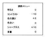
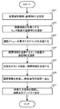
図2は、調整処理の処理手順を示すフローチャートであり、図3は、調整処理を行う際の調節メニュー画面を示すものである。
【0052】
映像および音声の調整を行うには、まず、システムコントローラ2からモニタ装置100に調節メニューの表示指示を行う。モニタ装置100では、システムコントローラ2から調節メニュー表示指示がきたら(S1)、映像表示デバイス30(以下、画面)上に調節メニューを表示する(S2)。調節メニュー表示後、システムコントローラ2より調節項目の選択(S3)があったら、選択項目の判定、すなわち、明るさの調節であるか(S11)、コントラストの調節であるか(S21)、色の濃さの調節であるか(S31)、・・・を判断する。
【0053】
明るさの調節であれば、調整値の変更入力の有無を判定し(S12)、調整値の入力があれば、映像信号処理部20に制御信号を送り(S13)、映像入力信号を映像信号処理部20で調整し、調整値を反映させた映像を画面に表示する(S14)。
【0054】
コントラストの調節であれば、上記と同様に、調整値の変更入力の有無を判定し(S22)、調整値の入力があれば、映像信号処理部20に制御信号を送り(S23)、映像信号処理部20で調整し、調整値を反映させた映像を画面に表示する(S24)。
【0055】
色の濃さの調節でも、上記同様、調整値の変更入力の有無を判定し(S32)、映像信号処理部20に制御信号を送り(S33)、調整値を反映させた映像を画面に表示する(S34)。
【0056】
他の項目においても同様であるが、音量調節の場合には、音声調節部60に制御信号を送り、音声出力信号を音声調節部60で調整し、調整値を反映させた音量で音声出力デバイス70(スピーカ)から出力する。
【0057】
上記処理が終了したら、調節メニュー終了指示であるかを判断し(S4)、さらに調整項目がある場合には、調節項目の選択待ち(S3)となり、終了の場合には、調節メニュー表示を終了して(S5)、映像および音声の調整処理を終了する。
【0058】
以上のように、本発明の第1の実施の形態のモニタ装置は、通信制御部を設け、システムコントローラやパソコンから制御情報を受信して、制御部が処理できる制御情報として制御部に入力させるので、本体操作部からの操作情報と同様に制御部で制御することができ、モニタ装置から離れた外部の制御端末から遠隔操作によりモニタ装置の映像および音声の調整を行うことができる。
【0059】
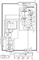
次に、本発明の第2の実施の形態のモニタ装置を、図4に示す。
【0060】
図4に示すように、第2の実施の形態のモニタ装置200は、システムコントローラ2と接続され、映像入力部(映像入力手段)10、映像信号処理部(映像信号処理手段)20、画像表示デバイス(画像表示手段)30、本体操作部80、通信制御部110およびモニタ制御部220を備え、さらに、モニタ制御部220は、レベル検出部(レベル検出手段)221、比較・演算部(比較演算手段)222、メモリ(信号設定値記憶手段)223、制御部(制御手段)224を備えている。
【0061】
映像入力部10、映像信号処理部20、画像表示デバイス30、本体操作部80および通信制御部110は、上記実施の形態で示した同一番号を付したものと同様のものである。
【0062】
レベル検出部221は、映像入力部10から映像入力信号を入力し、入力された映像入力信号の信号レベル値を検出するものである。比較・演算部222は、レベル検出部221に検出された信号レベル値と、メモリ223に記憶された基準設定レベル値または制御部224に選択された設定レベル値を比較して、前記信号レベル値と前記設定レベル値の差を演算し、差分信号レベル値を算出し、制御部224に出力するものである。
【0063】
メモリ223は、あらかじめ信号の設定レベル値を各項目ごとに記憶するものであり、各項目ごとに基準設定レベル値を指定した1つの基準設定レベル値情報、または、各項目をそれぞれ設定した設定レベル値情報を複数記憶するものである。
【0064】
制御部224は、比較・演算部222に演算された差分信号レベル値により、映像信号処理部20が変換する信号変換量を制御するものであり、また、メモリ223に記憶された複数の設定レベル値情報から、レベル検出部221に検出された信号レベル値に応じて、1つの設定レベル値情報を選択するものである。
【0065】
このようなモニタ装置200において、表示する映像をあらかじめ設定された最適状態に自動的に調節表示する処理手順を、以下に説明する。この場合、メモリ223は、各項目ごとに基準設定レベル値を指定した1つの基準設定レベル値情報を記憶している。
【0066】
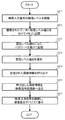
図5に、調節処理の処理手順を表すフローチャートを示す。
【0067】
まず、映像入力部10から映像入力信号を入力する。映像入力部10は、入力した映像入力信号を、映像信号処理部20とレベル検出部221に出力する(S211)。
【0068】
レベル検出部221に入力された映像入力信号は、Y(輝度)成分とC(色)成分のレベル情報が抜き取られ、それぞれの信号レベル値が検出され、比較・演算部222に出力される(S212)。
【0069】
ここで、メモリ223には、設計者が工場出荷前にあらかじめ一定の値を「基準設定レベル値」として設定してあるY成分とC成分のレベルが記録された「基準設定レベル値情報」が記録されている。
【0070】
制御部224は、上記メモリ223に記録された「基準設定レベル値情報」を呼び出し、比較・演算部222に送る(S214)。比較・演算部222では、上記レベル検出部221から出力された映像入力信号の各信号レベル値と、上記メモリ223から呼び出された「基準設定レベル値情報」の各信号レベル値を、比較・演算し、入力信号レベル情報と基準設定レベル値情報の各信号レベル値の差分情報(差分信号レベル値)を算出する。さらに、上記差分情報を画面上で実現させるための調節情報(Y成分の差分:明るさ、コントラスト、シャープネスで補完、C成分の差分:色の濃さ、色合いで補完)を演算して、演算結果を制御部224に送る(S215)。
【0071】
制御部224では、比較・演算部222で得られた調節情報を映像信号処理部20(輝度信号処理部26、色差信号処理部24)へ送る(S216)。映像信号処理部20では、制御部224から入力された調節情報により、映像信号入力部10から入力された映像入力信号を調節し、表示出力信号に変換して映像表示デバイス30へ出力する。映像表示デバイス30では、映像信号処理部20で最適に調節された表示出力信号を表示する(S217)。
【0072】
次に、表示する映像をあらかじめプリセットしておいて、登録された画像状態から選択して映像調節表示を行う処理手順を、以下に説明する。この場合、メモリ223は、各項目をそれぞれ設定した設定レベル値情報を複数記憶している。
【0073】
図6に、調節処理の処理手順を表すフローチャートを示す。
【0074】
まず、映像入力部10から映像入力信号を入力する。映像入力部10は、入力した映像入力信号を、映像信号処理部20とレベル検出部221に出力する(S221)。
【0075】
レベル検出部221に入力された映像入力信号は、Y(輝度)成分とC(色)成分のレベル情報が抜き取られ、それぞれの信号レベル値が検出され、比較・演算部222に出力される(S222)。
【0076】
ここで、メモリ223には、設計者が工場出荷前にあらかじめプリセットデータとして、様々な条件(明るくした映像、暗くした映像等)をもとにして設定してあるY成分とC成分のレベルが記録された「設定レベル値情報」が複数記録されている。
【0077】
次に、操作者はシステムコントローラ2もしくは本体操作部80から上記メモリ223に記憶されたプリセットデータから所望の設定レベル値情報を選択する。選択された設定レベル値情報は、比較・演算部222へ送られる(S224)。
【0078】
比較・演算部222では、上記レベル検出部221から出力された映像入力信号の各信号レベル値と、上記選択された設定レベル値情報の各信号レベル値を、比較・演算し、入力信号レベル情報と設定レベル値情報の各信号レベル値の差分情報(差分信号レベル値)を算出する。さらに、上記差分情報を画面上で実現させるための調節情報(Y成分の差分:明るさ、コントラスト、シャープネスで補完、C成分の差分:色の濃さ、色合いで補完)を演算して、演算結果を制御部224に送る(S225)。
【0079】
制御部224では、比較・演算部222で得られた調節情報を映像信号処理部20(輝度信号処理部26、色差信号処理部24)へ送る(S226)。映像信号処理部20では、制御部224から入力された調節情報により、映像信号入力部10から入力された映像入力信号を調節し、表示出力信号に変換して映像表示デバイス30へ出力する。映像表示デバイス30では、映像信号処理部20で最適に調節された表示出力信号を表示する(S227)。
【0080】
以上のように、本発明の第2の実施の形態のモニタ装置は、レベル検出部と比較・演算部とメモリを設け、制御部が、比較・演算部に演算された差分信号レベル値により、映像信号処理部が変換する信号変換量を制御するので、モニタ装置に入力された映像入力信号により自動的に調整量を制御でき、モニタ装置を監視する監視者がその都度調整を行わずとも、常に最適に調整された映像を見ることができる。
【0081】
また、メモリに複数のプリセットデータを記憶させ、レベル検出部に検出された信号レベル値に応じて調整量を選択させることにより、映像入力信号に応じた調整量に切り換えることができる。
【0082】
次に、本発明の第3の実施の形態のモニタ装置を、図7に示す。
【0083】
図7に示すように、第3の実施の形態のモニタ装置300は、システムコントローラ2と接続されるとともに、スイッチャー装置4と接続される。
【0084】
スイッチャー装置4は、複数の入力端子と映像出力端子および制御情報出力端子を備え、入力端子は複数のカメラ5a、5b、5c、5dをそれぞれ接続し、各カメラ5a、5b、5c、5dから入力される映像入力信号を切り換えて、映像信号を映像出力端子からモニタ装置300に出力するとともに、切り換えたカメラ5a、5b、5c、5dが接続される入力端子のチャネル番号情報を制御情報出力端子からモニタ装置300に出力する。
【0085】
また、モニタ装置300は、映像入力部(映像入力手段)10、映像信号処理部(映像信号処理手段)20、画像表示デバイス(画像表示手段)30、本体操作部80、通信制御部310およびモニタ制御部320を備え、さらに、モニタ制御部320は、メモリ(信号設定値記憶手段)323、制御部(制御手段)324を備えている。
【0086】
映像入力部10、映像信号処理部20、画像表示デバイス30および本体操作部80は、上記実施の形態で示した同一番号を付したものと同様のものである。
【0087】
通信制御部310は、このモニタ装置300を制御する外部のシステムコントローラ2および上記スイッチャー装置4と接続し、システムコントローラ2の制御信号およびスイッチャー装置4が切り換えたカメラ5a、5b、5c、5dが接続される入力端子のチャネル番号情報を入力するものであり、通信インターフェース部311および通信回路部312を有している。
【0088】
メモリ323は、本体操作部80もしくはシステムコントローラ2から通信制御部310を介して入力された映像レベルを調節した設定レベル値を記憶するものであり、各項目を設定した1組の設定レベル値を識別する設定レベル値IDとともに記憶するものである。
【0089】
制御部324は、本体操作部80もしくはシステムコントローラ2から通信制御部310を介して入力された映像レベルを調節した設定レベル値を、設定レベル値IDとともにメモリ323に記憶させるものであり、また、本体操作部80もしくはシステムコントローラ2から入力された設定レベル値、または、入力された設定レベル値IDからメモリ323に記憶された設定レベル値を呼び出して、映像信号処理部20が変換する信号変換量を制御するものである。
【0090】
このようなモニタ装置300において、表示する映像を調節表示する処理手順を、以下に説明する。
【0091】
図8に、調節処理の処理手順を表すフローチャートを示す。
【0092】
まず、本体操作部80もしくはシステムコントローラ2から、映像入力部10から入力された映像入力信号の映像レベル(明るさ、コントラスト、シャープネス、色の濃さ、色合い)を調節する(S311)。調節されたデータ、たとえば、明るさ:+5、コントラスト:−1、色の濃さ:+1、色合い:0、シャープネス:+10など、に設定レベル値IDを付けて、メモリ323に記憶する(S312)。
【0093】
ここで、設定レベル値を記憶する際に、設定レベル値IDごとにパスワードを設けて記憶(S313)することにより、登録者が意図せずに、他人が、または本人であっても、誤って設定値の変更や削除をしてしまうことを防止できる。
【0094】
以上の処理により、各項目の設定レベル値を登録することができる。
【0095】
次に、他人に設定レベル値を変更されてしまった、または、前に設定した設定レベル値に戻す場合の処理を説明する。
【0096】
本体操作部80もしくはシステムコントローラ2から設定レベル値IDを選択する(S314)。設定レベル値IDを選択すると、制御部324によりメモリ323に記憶された調節情報、設定レベル値の各項目が呼び出される(S315)。制御部324は、メモリ323より呼び出した調節情報を映像信号処理部20(輝度信号処理部26、色差信号処理部24)へ送る(S316)。映像信号処理部20では、制御部324から入力された調節情報により、映像信号入力部10から入力された映像入力信号を調節し、表示出力信号に変換して映像表示デバイス30へ出力する。映像表示デバイス30では、映像信号処理部20で調節された表示出力信号を表示する(S317)。
【0097】
次に、複数のカメラを切り換えて表示させるスイッチャー装置からの映像を、調節表示する処理手順を、以下に説明する。
【0098】
図9に、調節処理の処理手順を表すフローチャートを示す。
【0099】
まず、本体操作部80もしくはシステムコントローラ2から、スイッチャー装置4が切り換えるチャネル(スイッチャー装置4が出力する映像の入力元カメラ、入力端子番号)ごとに、監視者が見やすい映像レベル(明るさ、コントラスト、シャープネス、色の濃さ、色合い)を調節し(S321)、調節されたデータをそれぞれ設定レベル値IDを付けて、メモリ323に記憶する(S322)。必要ならば、上記と同様に、設定レベル値IDごとにパスワードを設けて記憶(S323)する。
【0100】
次に、カメラのチャネル(スイッチャー装置4の入力端子番号)と上記設定した設定レベル値IDをリンクさせる(S324)。したがって、上記チャネルごとの設定は全てのチャネルについて設定せずとも、1ch(チャネル)と2chの設定を同じとする場合には、1chの設定だけを行って、1chと2chに設定する設定レベル値IDを、1chで設定した設定レベル値IDとすれば良い。
【0101】
以上の処理により、各チャネルの設定レベル値を登録しておく。
【0102】
次に、スイッチャー装置4によりチャネルが切り換えられると、スイッチャー装置4が切り換えたチャネル番号を、通信制御部310により入力し、制御部324に入力させる(S325)。制御部324では、通信制御部310を介して入力したスイッチャー装置4のチャネル番号から、メモリ323に記憶したリンクしている設定レベル値IDの調節情報を呼び出す(326)。さらに、制御部324は、メモリ323より呼び出した調節情報を映像信号処理部20(輝度信号処理部26、色差信号処理部24)へ送る(S327)。映像信号処理部20では、制御部324から入力された調節情報により、映像信号入力部10から入力された映像入力信号を調節し、表示出力信号に変換して映像表示デバイス30へ出力する。映像表示デバイス30では、映像信号処理部20で調節された表示出力信号を表示する(S328)。
【0103】
以上のように、本発明の第3の実施の形態のモニタ装置は、通信制御部とメモリと制御部を設け、メモリに記憶する調整量をIDを付けて記憶し、制御部が、IDを指定することによりメモリ上の調整量を呼び出すので、映像の調整を行う際に、その都度調整量を入力せずにIDの入力だけであらかじめ設定した調整量に変更することができ、簡単に素早く要求した調整量として、所望の画像状態に修正することができる。
【0104】
また、複数のカメラを接続して画像表示を切り換える場合に、カメラの信号が入力される番号と調整量をリンクさせ、映像入力信号が入力されたカメラの識別情報を入力するので、カメラが切り換わるたびにその都度調整量を変更せずとも自動的にカメラにあった最適な調整量とすることができる。
【0105】
次に、本発明の第4の実施の形態のモニタ装置を、図10に示す。
【0106】
図10に示すように、第4の実施の形態のモニタ装置400は、システムコントローラ2と接続されるとともに、他のモニタ装置400と、たとえばディージーチェーンで接続される。システムコントローラ2は、直接、または、モニタ装置400を介して、複数のモニタ装置400と接続され、複数のモニタ装置400を制御するものである。
【0107】
また、モニタ装置400は、映像入力部(映像入力手段)10、映像信号処理部(映像信号処理手段)20、画像表示デバイス(画像表示手段)30、音声入力部(音声入力手段)50、音声調節部(音声信号処理手段)60、音声出力デバイス(音声出力手段)70、本体操作部80、メニュー表示用キャラクタジェネレータ部90、通信制御部410およびモニタ制御部(制御手段)420を備えている。
【0108】
映像入力部10、映像信号処理部20、画像表示デバイス30、音声入力部50、音声調節部60、音声出力デバイス70、本体操作部80およびメニュー表示用キャラクタジェネレータ部90は、上記実施の形態で示した同一番号を付したものと同様のものである。
【0109】
通信制御部410は、このモニタ装置400を制御する外部のシステムコントローラ2および他のモニタ装置400と接続し、システムコントローラ2の制御信号および他のモニタ装置400と制御情報の送受信を行うものであり、通信インターフェース部411および通信回路部412を有している。
【0110】
モニタ制御部420は、本体操作部80もしくは通信制御部410を介して入力された映像レベルを調節した設定レベル値を、設定レベル値IDとともに記憶させるものであり、また、本体操作部80もしくは通信制御部410を介して入力された設定レベル値、または、入力された設定レベル値IDから記憶された設定レベル値を呼び出して、映像信号処理部20が変換する信号変換量を制御するものである。さらに、モニタ制御部420は、上記設定レベル値を通信制御部410に受け渡して、他のモニタ装置400に送信させるものである。
【0111】
このようなシステムコントローラ2および複数のモニタ装置400を備えたシステムにおいて、複数のモニタ装置400に対して、表示する映像を同時に遠隔調整を行う処理手順を、以下に説明する。
【0112】
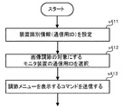
図11に、調節処理の処理手順を表すフローチャートを示す。
【0113】
調節処理に先立ち、各モニタ装置400に、個々のモニタ装置400を識別する装置識別情報(通信用ID)を設定する(S411)。この通信用IDの設定は、処理のたびに設定しても良いし、一度設定したものを次から使用するようにしても良いが、あらかじめ設定されている装置IDに対応したものを使用すると良い。設定されている装置IDをそのまま使用する場合には、わざわざ設定せずとも良い。
【0114】
調節処理では、システムコントローラ2から、画像調節の対象にするモニタ装置400の通信用IDを選択する(S412)。選択されなかったモニタ装置400は、選択待ちの状態が続く。次に、調節メニューを表示するコマンドをシステムコントローラ2から送信する(S413)。送信されたコマンドは、通信制御部410を介して、モニタ制御部420に入力され、以下、上記実施の形態と同様に、画像調節を行うことができる。
【0115】
次に、複数のモニタ装置の映像を同じ調整レベル値とする処理手順を、以下に説明する。
【0116】
図12に、調節処理の処理手順を表すフローチャートを示す。
【0117】
調節処理に先立ち、上記処理同様、各モニタ装置400に、個々のモニタ装置400を識別する装置識別情報(通信用ID)を設定する(S421)。
【0118】
調節処理では、システムコントローラ2から、画像調節の対象にするモニタ装置400aの通信用IDを選択する(S422)。調節メニューを表示するコマンドをシステムコントローラ2から送信する(S423)。送信されたコマンドは、通信制御部410を介して、モニタ制御部420に入力され、以下、上記実施の形態と同様に、画像調節を行う。
【0119】
次に、システムコントローラ2から調節したモニタ装置400aと画像設定を同じとしたいモニタ装置400bの通信用IDを選択する(S424)。この選択は、複数のモニタ装置400a、400bを同時に選択可能である。システムコントローラ2から「送信」のコマンドを画像調節したモニタ装置400aに対して送信する。
【0120】
モニタ装置400aは、通信制御部410を介して上記「送信」コマンドを受信する。モニタ制御部420は、上記設定した調節情報を通信制御部410に受け渡し、通信制御部410は、システムコントローラ2に選択された送信先のモニタ装置400bに、上記調節情報を送信する(S425)。複数のモニタ装置400bが選択されている場合には、それぞれに送信する。
【0121】
モニタ装置400bは、通信制御部410を介して上記調節情報を受信する。モニタ制御部420は、受信した調節情報を映像信号処理部20(輝度信号処理部26、色差信号処理部24)へ送る(S426)。映像信号処理部20では、モニタ制御部420から入力された調節情報により、映像信号入力部10から入力された映像入力信号を調節し、表示出力信号に変換して映像表示デバイス30へ出力する。映像表示デバイス30では、映像信号処理部20で調節された表示出力信号を表示する(S427)。
【0122】
以上のように、本発明の第4の実施の形態のモニタ装置およびシステムコントローラは、通信制御部と制御部を設け、複数のモニタ装置を接続し、各モニタ装置を識別する装置識別情報を送受信するので、複数のモニタ装置に対して、映像の調整を同時に遠隔調整を行うことができる。
【0123】
また、画像調整を行ったモニタ装置の調整情報を、他のモニタ装置に送信することができるので、複数台のモニタ装置を同じ設定にすることができ、画像を同じ絵柄にすることが簡単にできるとともに、他のモニタ装置の設定レベル値に調整にしてから調整し直すことができ、調整量を少なくし、簡単に行うことができる。
【0124】
【発明の効果】
以上説明したように、本発明によればモニタ装置を制御するシステムコントローラから制御信号を受信して、制御手段が処理できる制御情報として制御手段に入力させ、制御手段が前記制御信号により映像信号処理手段が変換する信号変換量を制御することにより、本体操作部からの操作情報と同様に制御手段で映像信号処理手段を制御でき、モニタ装置から離れた外部の制御端末から遠隔操作によりモニタ装置の映像の調整を行うことができるというすぐれた効果を有するモニタ装置を提供することができるものである。
【図面の簡単な説明】
【図1】本発明の第1の実施の形態のモニタ装置を示すブロック図
【図2】本発明の調整処理を示すフローチャート
【図3】本発明の調節メニュー画面
【図4】本発明の第2の実施の形態のモニタ装置を示すブロック図
【図5】本発明の調整処理を示すフローチャート
【図6】本発明の調整処理を示すフローチャート
【図7】本発明の第3の実施の形態のモニタ装置を示すブロック図
【図8】本発明の調整処理を示すフローチャート
【図9】本発明の調整処理を示すフローチャート
【図10】本発明の第4の実施の形態のモニタ装置を示すブロック図
【図11】本発明の調整処理を示すフローチャート
【図12】本発明の調整処理を示すフローチャート
【図13】従来のモニタ装置を示すブロック図
【符号の説明】
2 システムコントローラ
3 パソコン
4 スイッチャー装置
5a、5b、5c、5d カメラ
10 映像入力部
20 映像信号処理部
21 Y/C分離部
22 BPF部
23 復調部
24 色差信号処理部
25 LPF部
26 輝度信号処理部
27 RGB信号処理部
30 画像表示デバイス
50 音声入力部
60 音声調節部
70 音声出力デバイス
80 本体操作部
90 メニュー表示用キャラクタジェネレータ部
100、200、300、400 モニタ装置
110、310、410 通信制御部
111、311、411 通信インターフェース部
112、312、412 通信回路部
120、220、320、420 モニタ制御部
221 レベル検出部
222 比較・演算部
223、323 メモリ
224、324 制御部
900 モニタ装置
910 映像入力部
920 映像信号処理部
930 画像表示デバイス
940 モニタ制御部
980 本体操作部[0001]
BACKGROUND OF THE INVENTION
The present invention relates to a monitor device used for a monitoring device or the like, and in particular, adjustment of video and audio displayed on the monitor device, for example, if video adjustment is performed, by inputting an adjustment amount such as contrast and hue, The present invention relates to a monitor device that adjusts luminance and color difference.
[0002]
[Prior art]
Conventionally, in a monitor device, display information is displayed on a display unit in accordance with a video input signal. The monitor device is used in various environments, and the video input signal displayed on the monitor device also displays images of various environments. Therefore, the monitor device monitor can display information displayed on the display unit of the monitor device. In order to improve the visibility, the brightness of the displayed image is adjusted.
[0003]
FIG. 13 shows an example of a conventional monitor device.
[0004]
As shown in FIG. 13, the
[0005]
The
[0006]
The
[0007]
In such a
[0008]
[Problems to be solved by the invention]
However, in such a conventional monitor device, the operator who monitors the monitor device cannot adjust the image when the device main body is installed in a place such as a high place that cannot be reached by the operator's hand. There was a problem.
[0009]
In addition, since adjustments must be made in accordance with the video input signal using the main unit operation unit, this is suitable every time the input source of the video is switched, especially when multiple images are connected and displayed. Since the amount of adjustment changes, there is a problem that adjustment must be performed while looking at the screen each time.
[0010]
The present invention has been made to solve such a problem, and provides a monitor device capable of easily adjusting a display image.
[0011]
[Means for Solving the Problems]
The monitor apparatus of the present invention includes a video input means for inputting a video signal, a video signal processing means for performing video processing on the video signal input to the video input means and converting it into a display output signal, and the video signal processing means. In a monitor device comprising: an image display means for outputting a display output signal converted in step (a); and a control means for controlling a signal conversion amount for converting the video signal to the display output signal in the video signal processing means.Signal setting value input means for inputting the signal setting level value, level detection means for detecting the signal level value of the video signal input to the video input means, and signal setting value for storing the input setting level value A storage means, a calculation means for calculating a difference between the signal level value and the set level value, and calculating a difference signal level value;WithThe control means uses the differential signal level value calculated by the comparison calculation means,The video signal processing means controls the signal conversion amount to be converted.
[0018]
With this configuration, the signal setting level value desired by the monitor supervisor can be input by the signal setting value input means and stored in the signal setting value storage means, so that the monitor supervisor follows the signal setting level value desired by the monitor supervisor. The image state can be corrected.
[0019]
Furthermore, the monitoring apparatus of the present invention further includes level value identification information input means for inputting setting level value identification information for specifying the setting level value, and the signal setting value storage means is input by the signal setting value input means. The set level value of the received signal is stored together with the set level value identification information, and the comparison operation means detects the signal level value detected by the level detection means and the set level value input to the level value identification information input means. The difference signal level value is calculated by calculating a difference from a set level value specified by the identification information.
[0020]
With this configuration, the setting level value of the video signal is stored together with the setting level value identification information for identifying this setting level value. By specifying the setting level value identification information, the set setting level value is called and this setting level value is identified. Since the video is adjusted according to the level value, when adjusting the video, the adjustment level can be changed to the preset level just by inputting the set level value identification information without entering the adjustment level each time. The requested adjustment amount can be corrected to a desired image state.
[0021]
Further, in the monitor device of the present invention, the signal set value input means inputs a password together with the set level value, the signal set value storage means records the set level value together with the password, and the signal set value The stored setting level value is updated only when a new setting level value is input together with the password from the input means.
[0022]
With this configuration, since the storage of the setting level value is protected by the password, it is possible to prevent the setting value from being changed or deleted without the intention of the registrant.
[0023]
The monitor device of the present invention isVideo input means for inputting a video signal, video signal processing means for performing video processing on the video signal input to the video input means and converting it to a display output signal, and a display output signal converted by the video signal processing means A signal for inputting a set level value of a signal in a monitor device comprising: an image display means for outputting a signal; and a control means for controlling a signal conversion amount for converting the video signal into the display output signal in the video signal processing means. Setting value input means, level detection means for detecting the signal level value of the video signal input to the video input means, and output device for identifying the output device of the signal output source of the video signal input to the video input means Output device identification information input means for inputting identification information, and a signal for storing the input setting level value in association with the output device identification information and the setting level value. A difference between the set value storage means, the signal level value detected by the level detection means, and the set level value associated with the output device identification information input to the output device identification information input means; Comparison operation means for calculating a signal level value, and the control means controls the signal conversion amount converted by the video signal processing means according to the difference signal level value calculated by the comparison operation means. It has the structure.
[0024]
With this configuration, when a plurality of video output devices such as cameras are connected and image display is switched, output device identification information of the signal output source of the video signal is stored in association with the set level value, and the video signal is input. Since the setting level value is switched according to the output device, the optimum adjustment amount suitable for the video signal of the video input source can be automatically obtained.
[0025]
Furthermore, the monitor device of the present invention includes:Video input means for inputting a video signal, video signal processing means for performing video processing on the video signal input to the video input means and converting it to a display output signal, and a display output signal converted by the video signal processing means A signal for inputting a set level value of a signal in a monitor device comprising: an image display means for outputting a signal; and a control means for controlling a signal conversion amount for converting the video signal into the display output signal in the video signal processing means. The set value input means, the level detection means for detecting the signal level value of the video signal input to the video input means, the signal set value storage means for storing the input set level value, and the monitor device are identified. Setting level value transmitting means for transmitting the monitoring device identification information to be performed and the setting level value stored in the signal setting value storage means, the signal level value and the setting level And a comparison calculation means for calculating a difference signal level value and calculating a difference signal level value. The control means converts the video signal processing means according to the difference signal level value calculated by the comparison calculation means. Control the amount of signal conversionIt has the structure characterized by this.
[0026]
With this configuration, the adjustment information of the monitor device that performed the image adjustment can be designated by the monitor device identification information and transmitted to other monitor devices, so that a plurality of monitor devices can be set to the same setting, The images can be easily made the same pattern, and can be adjusted again after adjusting to the set level value of another monitor device, and the adjustment amount is small and can be easily performed.
[0027]
The monitor device of the present invention isVideo input means for inputting a video signal, video signal processing means for performing video processing on the video signal input to the video input means and converting it to a display output signal, and a display output signal converted by the video signal processing means An external display device for controlling the monitor device in a monitor device comprising: an image display means for outputting a signal; and a control means for controlling a signal conversion amount for converting the video signal into the display output signal in the video signal processing means. Control signal input means for inputting a control signal from the monitor apparatus, monitor apparatus identification information of the own monitor apparatus for identifying the other monitor apparatus, and monitor apparatus identification information associated with the control signal input by the control signal input means. The monitor device identification information separating means to be separated and the monitor device identification information separated by the monitor device identification information separating means Determining means for determining whether the identification information is position identification information, and when the control means determines that the monitor apparatus identification information input by the determination means is the monitor identification information of the own monitor apparatus, A signal amount conversion amount converted by the video signal processing means is controlled by a control signal input to the control signal input means.It has the structure characterized by this.
[0028]
With this configuration, it is confirmed whether or not the monitor device identification information accompanying the input control information is the monitor device identification information of the own monitor, and only the control information of the own monitor is input. Even if connected, the control information of the own monitor can be distinguished and input, the monitor device can be accurately controlled, and the image can be adjusted simultaneously for a plurality of monitor devices. Become.
[0037]
DETAILED DESCRIPTION OF THE INVENTION
Hereinafter, embodiments of the present invention will be described with reference to the drawings.
[0038]
A monitor device according to a first embodiment of the present invention is shown in FIG. As shown in FIG. 1, a
[0039]
The
[0040]
The
[0041]
The
[0042]
The main
[0043]
The
[0044]
The
[0045]
In the system in which the
[0046]
Regardless of the
[0047]
Next, a case where the
[0048]
If the operation from the main
[0049]
In order to adjust the video and audio of the
[0050]
Below, the process sequence which adjusts the image | video and audio | voice of the
[0051]
FIG. 2 is a flowchart showing a processing procedure of the adjustment processing, and FIG. 3 shows an adjustment menu screen when performing the adjustment processing.
[0052]
In order to adjust video and audio, first, the
[0053]
If the brightness is adjusted, it is determined whether or not there is an input for changing the adjustment value (S12). If there is an input for the adjustment value, a control signal is sent to the video signal processing unit 20 (S13). The image adjusted by the
[0054]
If the contrast is to be adjusted, the presence / absence of an adjustment value change input is determined (S22), and if the adjustment value is input, a control signal is sent to the video signal processing unit 20 (S23). The image adjusted by the
[0055]
Also in the adjustment of the color density, as described above, it is determined whether or not an adjustment value change is input (S32), a control signal is sent to the video signal processing unit 20 (S33), and an image reflecting the adjustment value is displayed on the screen. (S34).
[0056]
The same applies to other items, but in the case of volume adjustment, a control signal is sent to the
[0057]
When the above processing is completed, it is determined whether or not the adjustment menu is instructed (S4). If there are further adjustment items, the adjustment item selection waits (S3). Then, the video and audio adjustment process is finished (S5).
[0058]
As described above, the monitoring apparatus according to the first embodiment of the present invention includes a communication control unit, receives control information from a system controller or a personal computer, and causes the control unit to input control information that can be processed by the control unit. Therefore, it can be controlled by the control unit in the same manner as the operation information from the main body operation unit, and the video and audio of the monitor device can be adjusted by remote operation from an external control terminal remote from the monitor device.
[0059]
Next, a monitor device according to a second embodiment of the present invention is shown in FIG.
[0060]
As shown in FIG. 4, the
[0061]
The
[0062]
The level detection unit 221 receives a video input signal from the
[0063]
The
[0064]
The
[0065]
A processing procedure for automatically adjusting and displaying an image to be displayed in a preset optimum state in such a
[0066]
FIG. 5 is a flowchart showing the procedure of the adjustment process.
[0067]
First, a video input signal is input from the
[0068]
In the video input signal input to the level detection unit 221, the level information of the Y (luminance) component and the C (color) component is extracted, and the respective signal level values are detected and output to the comparison / calculation unit 222 ( S212).
[0069]
Here, in the
[0070]
The
[0071]
The
[0072]
Next, a processing procedure for presetting the video to be displayed and selecting the registered image state to perform video adjustment display will be described below. In this case, the
[0073]
FIG. 6 is a flowchart showing the procedure of the adjustment process.
[0074]
First, a video input signal is input from the
[0075]
In the video input signal input to the level detection unit 221, the level information of the Y (luminance) component and the C (color) component is extracted, and the respective signal level values are detected and output to the comparison / calculation unit 222 ( S222).
[0076]
Here, in the
[0077]
Next, the operator selects desired setting level value information from the preset data stored in the
[0078]
The comparison /
[0079]
The
[0080]
As described above, the monitor device according to the second embodiment of the present invention includes the level detection unit, the comparison / calculation unit, and the memory, and the control unit uses the difference signal level value calculated by the comparison / calculation unit, Since the signal conversion amount converted by the video signal processing unit is controlled, the adjustment amount can be automatically controlled by the video input signal input to the monitor device, and the monitor who monitors the monitor device does not adjust each time. You can always see the optimally adjusted video.
[0081]
Further, by storing a plurality of preset data in the memory and causing the level detection unit to select an adjustment amount according to the detected signal level value, it is possible to switch to the adjustment amount according to the video input signal.
[0082]
Next, a monitor device according to a third embodiment of the present invention is shown in FIG.
[0083]
As shown in FIG. 7, the
[0084]
The
[0085]
The
[0086]
The
[0087]
The
[0088]
The
[0089]
The
[0090]
A processing procedure for adjusting and displaying a video to be displayed in such a
[0091]
FIG. 8 is a flowchart showing the procedure of the adjustment process.
[0092]
First, the video level (brightness, contrast, sharpness, color density, hue) of the video input signal input from the
[0093]
Here, when storing the setting level value, by providing a password for each setting level value ID and storing it (S313), even if the registrant does not intend and another person or himself / herself is mistaken, It is possible to prevent the setting value from being changed or deleted.
[0094]
Through the above processing, the setting level value of each item can be registered.
[0095]
Next, a process in the case where the setting level value has been changed by another person or returned to the setting level value set previously will be described.
[0096]
A setting level value ID is selected from the main
[0097]
Next, a processing procedure for adjusting and displaying an image from the switcher device that switches and displays a plurality of cameras will be described below.
[0098]
FIG. 9 is a flowchart showing the procedure of the adjustment process.
[0099]
First, for each channel (switching
[0100]
Next, the camera channel (input terminal number of the switcher device 4) is linked to the set setting level value ID (S324). Therefore, even if the setting for each channel is not set for all channels, if the settings of 1ch (channel) and 2ch are the same, only the setting of 1ch is performed and the setting level value is set to 1ch and 2ch. The ID may be a set level value ID set in 1ch.
[0101]
Through the above processing, the setting level value of each channel is registered.
[0102]
Next, when the channel is switched by the
[0103]
As described above, the monitoring device according to the third embodiment of the present invention includes the communication control unit, the memory, and the control unit, stores the adjustment amount stored in the memory with an ID, and the control unit stores the ID. Since the adjustment amount in the memory is called by specifying, when adjusting the image, it can be changed to the adjustment amount set in advance just by entering the ID without inputting the adjustment amount each time, and it can be done quickly and easily. The requested adjustment amount can be corrected to a desired image state.
[0104]
Also, when switching the image display by connecting multiple cameras, the camera signal input number and the adjustment amount are linked and the identification information of the camera to which the video input signal is input is input. It is possible to automatically set the optimum adjustment amount suitable for the camera without changing the adjustment amount each time the switch is made.
[0105]
Next, a monitor device according to a fourth embodiment of the present invention is shown in FIG.
[0106]
As shown in FIG. 10, the monitor device 400 of the fourth embodiment is connected to the
[0107]
The monitor device 400 includes a video input unit (video input unit) 10, a video signal processing unit (video signal processing unit) 20, an image display device (image display unit) 30, an audio input unit (audio input unit) 50, an audio. An adjustment unit (audio signal processing unit) 60, an audio output device (audio output unit) 70, a main
[0108]
The
[0109]
The
[0110]
The
[0111]
In the system including such a
[0112]
FIG. 11 is a flowchart showing the procedure of the adjustment process.
[0113]
Prior to the adjustment processing, device identification information (communication ID) for identifying each monitor device 400 is set in each monitor device 400 (S411). The communication ID may be set every time processing is performed, or the once set ID may be used from the next time. However, the ID corresponding to the preset device ID may be used. . If the set device ID is used as it is, it does not have to be set.
[0114]
In the adjustment process, the communication ID of the monitor device 400 that is the object of image adjustment is selected from the system controller 2 (S412). The monitor device 400 that has not been selected continues to wait for selection. Next, a command for displaying the adjustment menu is transmitted from the system controller 2 (S413). The transmitted command is input to the
[0115]
Next, a processing procedure for setting the same adjustment level value for images from a plurality of monitor devices will be described below.
[0116]
FIG. 12 is a flowchart showing the procedure of the adjustment process.
[0117]
Prior to the adjustment process, device identification information (communication ID) for identifying each monitor device 400 is set in each monitor device 400 as in the above-described process (S421).
[0118]
In the adjustment process, the communication controller ID of the monitor device 400a to be subjected to image adjustment is selected from the system controller 2 (S422). A command for displaying the adjustment menu is transmitted from the system controller 2 (S423). The transmitted command is input to the
[0119]
Next, the communication ID of the
[0120]
The monitor device 400 a receives the “send” command via the
[0121]
The
[0122]
As described above, the monitor device and system controller according to the fourth embodiment of the present invention are provided with a communication control unit and a control unit, connect a plurality of monitor devices, and transmit / receive device identification information for identifying each monitor device. As a result, it is possible to remotely adjust the image simultaneously for a plurality of monitor devices.
[0123]
In addition, since the adjustment information of the monitor device that performed the image adjustment can be transmitted to other monitor devices, a plurality of monitor devices can be set to the same setting, and the image can be easily set to the same pattern. In addition, the adjustment can be made again after adjusting to the setting level value of another monitor device, and the adjustment amount can be reduced and the adjustment can be easily performed.
[0124]
【The invention's effect】
As described above, according to the present invention, a control signal is received from the system controller that controls the monitor device, and is input to the control unit as control information that can be processed by the control unit. By controlling the signal conversion amount converted by the means, the video signal processing means can be controlled by the control means in the same manner as the operation information from the main body operation unit, and the monitor device can be remotely controlled from an external control terminal remote from the monitor device. It is possible to provide a monitor device having an excellent effect of being able to adjust an image.
[Brief description of the drawings]
FIG. 1 is a block diagram showing a monitor device according to a first embodiment of the present invention.
FIG. 2 is a flowchart showing adjustment processing according to the present invention.
FIG. 3 is an adjustment menu screen of the present invention.
FIG. 4 is a block diagram showing a monitor device according to a second embodiment of the present invention.
FIG. 5 is a flowchart showing adjustment processing according to the present invention.
FIG. 6 is a flowchart showing adjustment processing according to the present invention.
FIG. 7 is a block diagram showing a monitor device according to a third embodiment of the present invention.
FIG. 8 is a flowchart showing adjustment processing according to the present invention.
FIG. 9 is a flowchart showing adjustment processing according to the present invention.
FIG. 10 is a block diagram showing a monitor device according to a fourth embodiment of the present invention.
FIG. 11 is a flowchart showing adjustment processing according to the present invention.
FIG. 12 is a flowchart showing adjustment processing according to the present invention.
FIG. 13 is a block diagram showing a conventional monitor device
[Explanation of symbols]
2 System controller
3 PC
4 Switcher device
5a, 5b, 5c, 5d camera
10 Video input section
20 Video signal processor
21 Y / C separator
22 BPF
23 Demodulator
24 Color difference signal processor
25 LPF section
26 Luminance signal processor
27 RGB signal processor
30 Image display device
50 Voice input part
60 Voice control unit
70 Audio output device
80 Control unit
90 Character generator for menu display
100, 200, 300, 400 Monitor device
110, 310, 410 Communication control unit
111, 311, 411 Communication interface
112, 312, 412 Communication circuit section
120, 220, 320, 420 Monitor control unit
221 Level detector
222 Comparison / Calculation Unit
223, 323 memory
224, 324 control unit
900 Monitor device
910 Video input section
920 Video signal processor
930 image display device
940 Monitor control unit
980 Operation unit
Claims (6)
前記映像入力手段に入力された映像信号に映像処理を行い、表示出力信号に変換する映像信号処理手段と、
前記映像信号処理手段で変換された表示出力信号を出力する画像表示手段と、
前記映像信号処理手段において前記映像信号を前記表示出力信号に変換する信号変換量を制御する制御手段とを備えたモニタ装置において、
信号の設定レベル値を入力する信号設定値入力手段と、
前記映像入力手段に入力された映像信号の信号レベル値を検出するレベル検出手段と、
前記入力された設定レベル値を記憶する信号設定値記憶手段と、
前記信号レベル値と前記設定レベル値との差を演算し、差分信号レベル値を算出する比較演算手段と、を備え、
前記制御手段が、前記比較演算手段に演算された差分信号レベル値により、前記映像信号処理手段が変換する信号変換量を制御することを特徴とするモニタ装置。Video input means for inputting a video signal;
Video signal processing means for performing video processing on the video signal input to the video input means and converting it to a display output signal;
Image display means for outputting a display output signal converted by the video signal processing means;
A monitor device comprising: control means for controlling a signal conversion amount for converting the video signal into the display output signal in the video signal processing means;
A signal set value input means for inputting a set level value of the signal;
Level detection means for detecting a signal level value of the video signal input to the video input means;
Signal setting value storage means for storing the inputted setting level value;
Comparing calculation means for calculating a difference between the signal level value and the set level value and calculating a differential signal level value ,
The monitor device , wherein the control means controls a signal conversion amount converted by the video signal processing means based on a difference signal level value calculated by the comparison calculation means .
前記信号設定値記憶手段が、前記信号設定値入力手段により入力された信号の設定レベル値を前記設定レベル値識別情報とともに記憶し、
前記比較演算手段が、前記レベル検出手段に検出された信号レベル値と、前記レベル値識別情報入力手段に入力された設定レベル値識別情報により特定される設定レベル値との差を演算して、前記差分信号レベル値を算出することを特徴とする請求項1に記載のモニタ装置。 Level value identification information input means for inputting setting level value identification information for specifying the setting level value;
The signal set value storage means stores the set level value of the signal input by the signal set value input means together with the set level value identification information;
The comparison calculation means calculates the difference between the signal level value detected by the level detection means and the set level value specified by the set level value identification information input to the level value identification information input means, The monitor apparatus according to claim 1, wherein the differential signal level value is calculated .
前記信号設定値記憶手段が、前記設定レベル値を前記パスワードとともに記録し、前記信号設定値入力手段から前記パスワードとともに新たな設定レベル値が入力されたときのみ前記記憶した設定レベル値を更新することを特徴とする請求項1または2に記載のモニタ装置。 The signal set value input means inputs a password together with the set level value,
The signal set value storage means records the set level value together with the password, and updates the stored set level value only when a new set level value is input together with the password from the signal set value input means. The monitor device according to claim 1 or 2.
前記映像入力手段に入力された映像信号に映像処理を行い、表示出力信号に変換する映像信号処理手段と、
前記映像信号処理手段で変換された表示出力信号を出力する画像表示手段と、
前記映像信号処理手段において前記映像信号を前記表示出力信号に変換する信号変換量を制御する制御手段とを備えたモニタ装置において、
信号の設定レベル値を入力する信号設定値入力手段と、
前記映像入力手段に入力された映像信号の信号レベル値を検出するレベル検出手段と、
前記映像入力手段に入力された映像信号の信号出力元の出力装置を識別する出力装置識別情報を入力する出力装置識別情報入力手段と、
前記入力された設定レベル値を、前記出力装置識別情報と前記設定レベル値と関連づけて記憶する信号設定値記憶手段と、
前記レベル検出手段が検出した信号レベル値と、前記出力装置識別情報入力手段に入力された出力装置識別情報に関連づけられた前記設定レベル値との差を演算し、前記差分信号レベル値を算出する比較演算手段とを備え、
前記制御手段が、前記比較演算手段に演算された差分信号レベル値により、前記映像信号処理手段が変換する信号変換量を制御することを特徴とするモニタ装置。 Video input means for inputting a video signal;
Video signal processing means for performing video processing on the video signal input to the video input means and converting it to a display output signal;
Image display means for outputting a display output signal converted by the video signal processing means;
A monitor device comprising: control means for controlling a signal conversion amount for converting the video signal into the display output signal in the video signal processing means;
A signal set value input means for inputting a set level value of the signal;
Level detection means for detecting a signal level value of the video signal input to the video input means;
Output device identification information input means for inputting output device identification information for identifying an output device of a signal output source of the video signal input to the video input means;
Signal setting value storage means for storing the input setting level value in association with the output device identification information and the setting level value;
The difference signal level value is calculated by calculating a difference between the signal level value detected by the level detection means and the set level value associated with the output device identification information input to the output device identification information input means. A comparison operation means,
The monitor device , wherein the control means controls a signal conversion amount converted by the video signal processing means based on a difference signal level value calculated by the comparison calculation means .
前記映像入力手段に入力された映像信号に映像処理を行い、表示出力信号に変換する映像信号処理手段と、
前記映像信号処理手段で変換された表示出力信号を出力する画像表示手段と、
前記映像信号処理手段において前記映像信号を前記表示出力信号に変換する信号変換量を制御する制御手段とを備えたモニタ装置において、
信号の設定レベル値を入力する信号設定値入力手段と、
前記映像入力手段に入力された映像信号の信号レベル値を検出するレベル検出手段と、
前記入力された設定レベル値を記憶する信号設定値記憶手段と、
モニタ装置の識別を行うモニタ装置識別情報と、前記信号設定値記憶手段に記憶された設定レベル値とを送信する設定レベル値送信手段と、
前記信号レベル値と前記設定レベル値との差を演算し、差分信号レベル値を算出する比較演算手段とを備え、
前記制御手段が、前記比較演算手段に演算された差分信号レベル値により、前記映像信号処理手段が変換する信号変換量を制御することを特徴とするモニタ装置。 Video input means for inputting a video signal;
Video signal processing means for performing video processing on the video signal input to the video input means and converting it to a display output signal;
Image display means for outputting a display output signal converted by the video signal processing means;
A monitor device comprising: control means for controlling a signal conversion amount for converting the video signal into the display output signal in the video signal processing means;
A signal set value input means for inputting a set level value of the signal;
Level detection means for detecting a signal level value of the video signal input to the video input means;
Signal setting value storage means for storing the inputted setting level value;
Setting level value transmitting means for transmitting monitoring apparatus identification information for identifying the monitoring apparatus and a setting level value stored in the signal setting value storage means;
Comparing calculation means for calculating a difference between the signal level value and the set level value and calculating a differential signal level value;
The monitor device , wherein the control means controls a signal conversion amount converted by the video signal processing means based on a difference signal level value calculated by the comparison calculation means .
前記映像入力手段に入力された映像信号に映像処理を行い、表示出力信号に変換する映像信号処理手段と、
前記映像信号処理手段で変換された表示出力信号を出力する画像表示手段と、
前記映像信号処理手段において前記映像信号を前記表示出力信号に変換する信号変換量を制御する制御手段とを備えたモニタ装置において、
前記モニタ装置を制御する外部制御機器から制御信号を入力する制御信号入力手段と、
他のモニタ装置との識別を行う自モニタ装置のモニタ装置識別情報と、
前記制御信号入力手段が入力する前記制御信号に付随するモニタ装置識別情報を分離するモニタ装置識別情報分離手段と、
前記モニタ装置識別情報分離手段に分離されたモニタ装置識別情報が、前記自モニタ装置のモニタ装置識別情報であるか否かを判断する判別手段とを備え、
前記制御手段が、前記判別手段で入力されたモニタ装置識別情報が自モニタ装置のモニタ識別情報であると判断されたとき、前記制御信号入力手段に入力された制御信号により、前記映像信号処理手段が変換する信号量変換量を制御することを特徴とするモニタ装置。 Video input means for inputting a video signal;
Video signal processing means for performing video processing on the video signal input to the video input means and converting it to a display output signal;
Image display means for outputting a display output signal converted by the video signal processing means;
A monitor device comprising: control means for controlling a signal conversion amount for converting the video signal into the display output signal in the video signal processing means;
Control signal input means for inputting a control signal from an external control device for controlling the monitor device;
Monitor device identification information of its own monitor device for identifying with other monitor devices;
Monitor device identification information separating means for separating monitor device identification information associated with the control signal input by the control signal input means;
Determining means for determining whether or not the monitor device identification information separated by the monitor device identification information separating means is the monitor device identification information of the own monitor device;
When the control means determines that the monitor apparatus identification information input by the determination means is the monitor identification information of the own monitor apparatus, the video signal processing means is determined by the control signal input to the control signal input means. A control device for controlling a signal amount conversion amount to be converted .
Priority Applications (1)
| Application Number | Priority Date | Filing Date | Title |
|---|---|---|---|
| JP2000366210A JP4718002B2 (en) | 2000-11-30 | 2000-11-30 | Monitor device and system controller |
Applications Claiming Priority (1)
| Application Number | Priority Date | Filing Date | Title |
|---|---|---|---|
| JP2000366210A JP4718002B2 (en) | 2000-11-30 | 2000-11-30 | Monitor device and system controller |
Publications (3)
| Publication Number | Publication Date |
|---|---|
| JP2002171459A JP2002171459A (en) | 2002-06-14 |
| JP2002171459A5 JP2002171459A5 (en) | 2007-12-13 |
| JP4718002B2 true JP4718002B2 (en) | 2011-07-06 |
Family
ID=18836866
Family Applications (1)
| Application Number | Title | Priority Date | Filing Date |
|---|---|---|---|
| JP2000366210A Expired - Fee Related JP4718002B2 (en) | 2000-11-30 | 2000-11-30 | Monitor device and system controller |
Country Status (1)
| Country | Link |
|---|---|
| JP (1) | JP4718002B2 (en) |
Families Citing this family (2)
| Publication number | Priority date | Publication date | Assignee | Title |
|---|---|---|---|---|
| EP1804232A4 (en) * | 2004-10-20 | 2012-03-28 | Fujitsu Ten Ltd | Display device, image quality adjustment method for display device, image quality adjustment device, and contrast adjustment device |
| TWI396467B (en) * | 2008-09-22 | 2013-05-11 | Acewell Internat Co Ltd | A regulating back light controller circuit and the same method for dashboard |
Citations (3)
| Publication number | Priority date | Publication date | Assignee | Title |
|---|---|---|---|---|
| JPH0410794A (en) * | 1990-04-27 | 1992-01-14 | Hitachi Ltd | Picture quality correcting circuit |
| JPH07295530A (en) * | 1994-04-27 | 1995-11-10 | Mitsubishi Electric Corp | Display monitor device and its adjusting method |
| JPH08242183A (en) * | 1995-03-01 | 1996-09-17 | Sanyo Electric Co Ltd | Display device |
-
2000
- 2000-11-30 JP JP2000366210A patent/JP4718002B2/en not_active Expired - Fee Related
Patent Citations (3)
| Publication number | Priority date | Publication date | Assignee | Title |
|---|---|---|---|---|
| JPH0410794A (en) * | 1990-04-27 | 1992-01-14 | Hitachi Ltd | Picture quality correcting circuit |
| JPH07295530A (en) * | 1994-04-27 | 1995-11-10 | Mitsubishi Electric Corp | Display monitor device and its adjusting method |
| JPH08242183A (en) * | 1995-03-01 | 1996-09-17 | Sanyo Electric Co Ltd | Display device |
Also Published As
| Publication number | Publication date |
|---|---|
| JP2002171459A (en) | 2002-06-14 |
Similar Documents
| Publication | Publication Date | Title |
|---|---|---|
| EP2493157B1 (en) | Image communication apparatus and its control method | |
| US5970162A (en) | Image input system having image pickup device capable of mirror-direction panning | |
| JPH09506217A (en) | Adaptive video conference system | |
| US20110115983A1 (en) | Image Display Apparatus to Which Multiple Image Sources Can Be Connected | |
| CN104956656A (en) | Imaging device, client device, imaging system, control method of imaging device, control method of client device, and control method of imaging system | |
| US5959686A (en) | Apparatus and method for controlling sub monitors in a video communication system | |
| JP4718002B2 (en) | Monitor device and system controller | |
| JP4580825B2 (en) | Display device | |
| JP3196806B2 (en) | Input signal switching device for video equipment | |
| JP2953280B2 (en) | Wide television receiver | |
| US5285285A (en) | Method of controlling first items that require prior CRT display and second items that require no prior display | |
| JPS63173478A (en) | Television display device | |
| JPH089282A (en) | Display device | |
| JPH07177496A (en) | Video communication equipment | |
| JPH08181958A (en) | Communication conference system, communication terminal equipment and camera operation device | |
| JPH06113306A (en) | Monitor television for interphone with camera | |
| JPH04183079A (en) | Electronic equipment | |
| KR100396682B1 (en) | Method and apparatus for processing PIP of video display device | |
| KR950007872B1 (en) | Apparatus and method for automatically switching audio/video | |
| JP3087349U (en) | Video signal display device | |
| JP3344041B2 (en) | Video display device | |
| WO2020016957A1 (en) | Video display device and video display method | |
| JPH0870448A (en) | Pan-tilt video doorphone system | |
| KR101276836B1 (en) | Image apparatus and controling method of input signal using it | |
| JPH0530507A (en) | Video conference system |
Legal Events
| Date | Code | Title | Description |
|---|---|---|---|
| A521 | Written amendment |
Free format text: JAPANESE INTERMEDIATE CODE: A523 Effective date: 20071026 |
|
| A621 | Written request for application examination |
Free format text: JAPANESE INTERMEDIATE CODE: A621 Effective date: 20071026 |
|
| A977 | Report on retrieval |
Free format text: JAPANESE INTERMEDIATE CODE: A971007 Effective date: 20101206 |
|
| A131 | Notification of reasons for refusal |
Free format text: JAPANESE INTERMEDIATE CODE: A131 Effective date: 20110111 |
|
| A521 | Written amendment |
Free format text: JAPANESE INTERMEDIATE CODE: A523 Effective date: 20110210 |
|
| A01 | Written decision to grant a patent or to grant a registration (utility model) |
Free format text: JAPANESE INTERMEDIATE CODE: A01 Effective date: 20110308 |
|
| A61 | First payment of annual fees (during grant procedure) |
Free format text: JAPANESE INTERMEDIATE CODE: A61 Effective date: 20110331 |
|
| R150 | Certificate of patent or registration of utility model |
Free format text: JAPANESE INTERMEDIATE CODE: R150 |
|
| FPAY | Renewal fee payment (event date is renewal date of database) |
Free format text: PAYMENT UNTIL: 20140408 Year of fee payment: 3 |
|
| LAPS | Cancellation because of no payment of annual fees |