JP4717455B2 - Image forming apparatus - Google Patents
Image forming apparatus Download PDFInfo
- Publication number
- JP4717455B2 JP4717455B2 JP2005026529A JP2005026529A JP4717455B2 JP 4717455 B2 JP4717455 B2 JP 4717455B2 JP 2005026529 A JP2005026529 A JP 2005026529A JP 2005026529 A JP2005026529 A JP 2005026529A JP 4717455 B2 JP4717455 B2 JP 4717455B2
- Authority
- JP
- Japan
- Prior art keywords
- cartridges
- closing member
- opening
- image forming
- forming apparatus
- Prior art date
- Legal status (The legal status is an assumption and is not a legal conclusion. Google has not performed a legal analysis and makes no representation as to the accuracy of the status listed.)
- Expired - Fee Related
Links
Images

Classifications
-
- G—PHYSICS
- G03—PHOTOGRAPHY; CINEMATOGRAPHY; ANALOGOUS TECHNIQUES USING WAVES OTHER THAN OPTICAL WAVES; ELECTROGRAPHY; HOLOGRAPHY
- G03G—ELECTROGRAPHY; ELECTROPHOTOGRAPHY; MAGNETOGRAPHY
- G03G21/00—Arrangements not provided for by groups G03G13/00 - G03G19/00, e.g. cleaning, elimination of residual charge
- G03G21/16—Mechanical means for facilitating the maintenance of the apparatus, e.g. modular arrangements
- G03G21/1604—Arrangement or disposition of the entire apparatus
- G03G21/1609—Arrangement or disposition of the entire apparatus for space saving, e.g. structural arrangements
-
- A—HUMAN NECESSITIES
- A01—AGRICULTURE; FORESTRY; ANIMAL HUSBANDRY; HUNTING; TRAPPING; FISHING
- A01G—HORTICULTURE; CULTIVATION OF VEGETABLES, FLOWERS, RICE, FRUIT, VINES, HOPS OR SEAWEED; FORESTRY; WATERING
- A01G9/00—Cultivation in receptacles, forcing-frames or greenhouses; Edging for beds, lawn or the like
- A01G9/12—Supports for plants; Trellis for strawberries or the like
- A01G9/122—Stakes
-
- G—PHYSICS
- G03—PHOTOGRAPHY; CINEMATOGRAPHY; ANALOGOUS TECHNIQUES USING WAVES OTHER THAN OPTICAL WAVES; ELECTROGRAPHY; HOLOGRAPHY
- G03G—ELECTROGRAPHY; ELECTROPHOTOGRAPHY; MAGNETOGRAPHY
- G03G21/00—Arrangements not provided for by groups G03G13/00 - G03G19/00, e.g. cleaning, elimination of residual charge
- G03G21/16—Mechanical means for facilitating the maintenance of the apparatus, e.g. modular arrangements
- G03G21/18—Mechanical means for facilitating the maintenance of the apparatus, e.g. modular arrangements using a processing cartridge, whereby the process cartridge comprises at least two image processing means in a single unit
- G03G21/1839—Means for handling the process cartridge in the apparatus body
- G03G21/1842—Means for handling the process cartridge in the apparatus body for guiding and mounting the process cartridge, positioning, alignment, locks
- G03G21/1853—Means for handling the process cartridge in the apparatus body for guiding and mounting the process cartridge, positioning, alignment, locks the process cartridge being mounted perpendicular to the axis of the photosensitive member
-
- G—PHYSICS
- G03—PHOTOGRAPHY; CINEMATOGRAPHY; ANALOGOUS TECHNIQUES USING WAVES OTHER THAN OPTICAL WAVES; ELECTROGRAPHY; HOLOGRAPHY
- G03G—ELECTROGRAPHY; ELECTROPHOTOGRAPHY; MAGNETOGRAPHY
- G03G2221/00—Processes not provided for by group G03G2215/00, e.g. cleaning or residual charge elimination
- G03G2221/16—Mechanical means for facilitating the maintenance of the apparatus, e.g. modular arrangements and complete machine concepts
- G03G2221/1603—Mechanical means for facilitating the maintenance of the apparatus, e.g. modular arrangements and complete machine concepts for multicoloured copies
-
- G—PHYSICS
- G03—PHOTOGRAPHY; CINEMATOGRAPHY; ANALOGOUS TECHNIQUES USING WAVES OTHER THAN OPTICAL WAVES; ELECTROGRAPHY; HOLOGRAPHY
- G03G—ELECTROGRAPHY; ELECTROPHOTOGRAPHY; MAGNETOGRAPHY
- G03G2221/00—Processes not provided for by group G03G2215/00, e.g. cleaning or residual charge elimination
- G03G2221/16—Mechanical means for facilitating the maintenance of the apparatus, e.g. modular arrangements and complete machine concepts
- G03G2221/1651—Mechanical means for facilitating the maintenance of the apparatus, e.g. modular arrangements and complete machine concepts for connecting the different parts
-
- G—PHYSICS
- G03—PHOTOGRAPHY; CINEMATOGRAPHY; ANALOGOUS TECHNIQUES USING WAVES OTHER THAN OPTICAL WAVES; ELECTROGRAPHY; HOLOGRAPHY
- G03G—ELECTROGRAPHY; ELECTROPHOTOGRAPHY; MAGNETOGRAPHY
- G03G2221/00—Processes not provided for by group G03G2215/00, e.g. cleaning or residual charge elimination
- G03G2221/16—Mechanical means for facilitating the maintenance of the apparatus, e.g. modular arrangements and complete machine concepts
- G03G2221/1678—Frame structures
- G03G2221/1687—Frame structures using opening shell type machines, e.g. pivoting assemblies
-
- G—PHYSICS
- G03—PHOTOGRAPHY; CINEMATOGRAPHY; ANALOGOUS TECHNIQUES USING WAVES OTHER THAN OPTICAL WAVES; ELECTROGRAPHY; HOLOGRAPHY
- G03G—ELECTROGRAPHY; ELECTROPHOTOGRAPHY; MAGNETOGRAPHY
- G03G2221/00—Processes not provided for by group G03G2215/00, e.g. cleaning or residual charge elimination
- G03G2221/16—Mechanical means for facilitating the maintenance of the apparatus, e.g. modular arrangements and complete machine concepts
- G03G2221/18—Cartridge systems
- G03G2221/183—Process cartridge
- G03G2221/1884—Projections on process cartridge for guiding mounting thereof in main machine
Landscapes
- Physics & Mathematics (AREA)
- General Physics & Mathematics (AREA)
- Engineering & Computer Science (AREA)
- Computer Vision & Pattern Recognition (AREA)
- Life Sciences & Earth Sciences (AREA)
- Environmental Sciences (AREA)
- Electrophotography Configuration And Component (AREA)
- Color Electrophotography (AREA)
Description
本発明は、複写機、プリンタ、ファクシミリ装置などの電子写真方式又は静電記録方式等を用いた画像形成装置に関し、特に装置本体に対して開閉する開閉手段を備えた画像形成装置に関するものである。 BACKGROUND OF THE INVENTION 1. Field of the Invention The present invention relates to an image forming apparatus using an electrophotographic system or an electrostatic recording system such as a copying machine, a printer, and a facsimile machine, and more particularly to an image forming apparatus provided with an opening / closing means that opens and closes the apparatus body. .
従来、特に電子写真方式を用いた画像形成装置には、像担持体である感光体とそれに作用する現像装置等の画像形成手段を一体にまとめたプロセスカートリッジや、画像が形成される紙等の転写材を収容する転写材収容部(紙カセット)等のような、ユーザが交換、補充を行うべき消耗品が含まれるユニットが備えられている。そして、プロセスカートリッジの交換時の操作性や紙カセットへの紙供給時の操作性を向上するために様々な提案が過去行われている。 2. Description of the Related Art Conventionally, in an image forming apparatus using an electrophotographic method in particular, a process cartridge in which image forming means such as a photoconductor as an image bearing member and a developing device acting on the photosensitive member are integrated, paper on which an image is formed, etc. A unit including a consumable item to be replaced or replenished by a user, such as a transfer material storage unit (paper cassette) for storing a transfer material, is provided. Various proposals have been made in the past in order to improve the operability when replacing the process cartridge and the operability when supplying paper to the paper cassette.
例えば、像担持体ユニット及び記録媒体カセットを着脱するためのそれぞれの着脱口を装置本体の同一側に配置し、且つそれぞれの着脱方向が同一であるものがある(例えば、特許文献1参照)。 For example, there is an apparatus in which the attachment / detachment openings for attaching / detaching the image carrier unit and the recording medium cassette are arranged on the same side of the apparatus main body and the attachment / detachment directions are the same (for example, see Patent Document 1).
しかしながらこの従来例は、垂直方向の軸(ヒンジ)を中心に前カバーが開く、言わゆる横開きタイプのものであり、前カバーはヒンジ側で片持ち支持されるため、装置本体に対する前カバーの位置精度を左右方向(ヒンジが有る側とヒンジが無い側)で同じにすることは困難であった。 However, this conventional example is a so-called laterally open type in which the front cover opens around a vertical axis (hinge), and the front cover is cantilevered on the hinge side. It was difficult to make the positional accuracy the same in the left-right direction (the side with the hinge and the side without the hinge).
特に前カバーに画像形成手段を取り付けた場合、画像形成手段の左右方向で位置精度が狂ってしまい良好な画像形成を行うことができないという問題があった。 In particular, when the image forming unit is attached to the front cover, there is a problem in that the position accuracy in the left and right direction of the image forming unit is out of order and good image formation cannot be performed.
そこで、水平方向の軸を中心にフロントカバーを下方へ開放(縦開きタイプ)してプロセスユニットの交換ができるものがある(例えば、特許文献2参照)。この装置によればフロントカバーの左右方向の位置精度は同じにすることができる。
ところで、従来の装置では、装置前面から用紙カセットの出し入れができることが記載されているが、フロントカバーの開放位置決め手段については記載されておらず、フロントカバーの開放位置によっては、プロセスユニットの交換はできるが、用紙カセットの出し入れの障害になる恐れがあった。 By the way, in the conventional apparatus, it is described that the paper cassette can be taken in and out from the front side of the apparatus, but there is no description about the opening positioning means of the front cover, and depending on the opening position of the front cover, the process unit can be replaced. Yes, but there was a risk of paper cassette insertion and removal.
特に、フルカラー画像形成装置では、それぞれ色毎に感光体を有するプロセスカートリッジが複数設けられており、交換頻度も増えることから用紙カセットを含めたメンテナンス性の向上が求められていた。又、複数のプロセスカートリッジを有すると装置が大型化しがちであるが、メンテナンス性を向上しても極力装置の大型化を抑えた装置が望まれていた。 In particular, in a full-color image forming apparatus, a plurality of process cartridges each having a photoconductor for each color are provided, and the frequency of replacement is increased. Therefore, improvement in maintainability including a paper cassette has been demanded. Further, the apparatus tends to increase in size when it has a plurality of process cartridges, but there has been a demand for an apparatus that suppresses the increase in the size of the apparatus as much as possible even if the maintainability is improved.
上記課題を解決するため本発明は、装置本体に対して開閉可能な開閉部材と、前記開閉部材を回転可能に支持する支持部材と、前記開閉部材を開放した状態の時、装置本体に対して着脱可能な複数のカートリッジと、前記開閉部材に保持され、前記開閉部材を閉じた状態の時に前記複数のカートリッジに対向し、前記開閉部材に連動して装置本体に対して開閉可能なベルトユニットと、記録材を収容し装置本体に対して着脱可能な記録材収容手段と、開放状態にある前記開閉部材を位置決めする位置決め手段と、を有し、前記複数のカートリッジの各々は、感光体と感光体に作用する少なくとも一つの画像形成部材とを一体的に備え、前記複数のカートリッジは、上下方向に並び、且つ記録材収容手段の上方に設けられており、前記複数のカートリッジの着脱と前記記録材収容手段の着脱は装置本体の同一面側から行われる画像形成装置において、前記複数のカートリッジの着脱を案内するガイド部材を有し、前記位置決め手段は、前記複数のカートリッジの着脱軌跡と前記記録材収容手段の着脱軌跡との間に形成される空間に、前記開閉部材及び前記ベルトユニットが位置するよう、前記開閉部材を位置決めし、前記開閉部材及び前記ベルトユニットが、前記複数のカートリッジの着脱軌跡と前記記録材収容手段の着脱軌跡との間に形成される空間に位置した状態で、前記複数のカートリッジは前記ガイド部材に案内されて斜め上方に引き抜き可能で、且つ、前記記録材収容手段は実質的に水平に引き抜き可能であることを特徴とするものである。 The present invention for solving the above problems, the opening and closing member capable of opening and closing with respect to the apparatus main body, a support member for rotatably supporting the opening and closing member, when in a state of opening the opening and closing member, the apparatus main body A plurality of detachable cartridges, and a belt unit that is held by the opening and closing member, faces the plurality of cartridges when the opening and closing member is closed, and can be opened and closed with respect to the apparatus main body in conjunction with the opening and closing member A recording material storing means for storing the recording material and detachable from the apparatus main body, and a positioning means for positioning the open / close member in an open state, wherein each of the plurality of cartridges includes a photosensitive member and a photosensitive member. integrally includes at least one of the imaging member acts on the body, the plurality of cartridges are aligned in the vertical direction and and provided above the recording material accommodating means, said plurality of Ca In the image forming apparatus removably detachable to the recording material containing unit cartridge is performed from the same side of the apparatus main body has a guide member for guiding the attachment and detachment of the plurality of cartridges, said positioning means, said plurality of cartridges of the space formed between the detachable locus and the detachable locus of said recording material accommodating means, such that the closing member and the belt unit is located, and positions the closing member, the closing member and the belt unit, The plurality of cartridges are guided by the guide member and can be withdrawn obliquely upward in a state where they are located in a space formed between the attachment / detachment locus of the plurality of cartridges and the attachment / detachment locus of the recording material storage means, and the recording material containing unit is characterized in capable der Rukoto pulling substantially horizontally.
前述した構成により本発明は、装置を大型化することなく着脱可能な複数の画像形成手段及び記録材収容手段の操作性を向上することができる。 With the above-described configuration, the present invention can improve the operability of a plurality of detachable image forming units and recording material accommodation units without increasing the size of the apparatus.
以下、図面に基づき本発明の実施例について説明する。 Embodiments of the present invention will be described below with reference to the drawings.
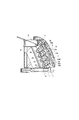
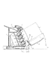
図1は本発明を実施した画像形成装置の一例である電子写真画像形成装置で、4色フルカラープリンタの概略構成を示す縦断面図である。 FIG. 1 is a longitudinal sectional view showing a schematic configuration of a four-color full-color printer as an electrophotographic image forming apparatus which is an example of an image forming apparatus embodying the present invention.
図1を用いて、この画像形成装置における画像形成動作について説明する。 An image forming operation in this image forming apparatus will be described with reference to FIG.
画像形成装置には、ブラック、シアン、マゼンタ、イエローのそれぞれの色毎に、画像形成手段であるプロセスカートリッジAa、Ab、Ac、Adが設けられている。プロセスカートリッジは、像担持体であるドラム状の電子写真感光体(感光体ドラム)1a、1b、1c、1dと、感光体ドラムに作用する少なくとも一つの画像形成部材とを一体的に備えている。そして、このプロセスカートリッジAa〜Adはそれぞれが個々に画像形成装置本体から着脱可能である。 The image forming apparatus is provided with process cartridges Aa, Ab, Ac, and Ad, which are image forming units, for each color of black, cyan, magenta, and yellow. The process cartridge is integrally provided with drum-shaped electrophotographic photosensitive members (photosensitive drums) 1a, 1b, 1c, and 1d that are image carriers, and at least one image forming member that acts on the photosensitive drum. . The process cartridges Aa to Ad can be individually attached to and detached from the image forming apparatus main body.
プロセスカートリッジAa〜Adはそれぞれ、感光体ドラムの他に、画像形成部材である帯電ローラ7a、7b、7c、7d、現像ローラ8a、8b、8c、8dを備えている。
Each of the process cartridges Aa to Ad is provided with charging rollers 7a, 7b, 7c, and 7d that are image forming members, and developing
それぞれのプロセスカートリッジAa〜Adにおいて、まず帯電工程において帯電ローラ7a〜7dにより、感光体ドラム1a〜1dの表面が均一に帯電され、潜像形成工程である露光工程にて、レーザー等の露光装置6によって画像を形成させたい部分が露光され、感光体ドラム1a〜1d上に静電潜像が形成される。そして、感光体ドラム1a〜1d上の静電潜像は、現像工程において現像ローラ8a〜8dによりそれぞれの色毎に現像剤(トナー)が付着され、静電潜像が現像される。このようにして感光体ドラム1a〜1d上に各色の現像剤像が形成される。
In each of the process cartridges Aa to Ad, first, in the charging process, the surfaces of the photosensitive drums 1a to 1d are uniformly charged by the charging rollers 7a to 7d, and an exposure device such as a laser is used in the exposure process as the latent image forming process. 6 is exposed to form an image, and electrostatic latent images are formed on the photosensitive drums 1a to 1d. Then, the electrostatic latent images on the photosensitive drums 1a to 1d are developed by developing agents (toners) for the respective colors by the developing
一方、このプロセスカートリッジAa〜Adにおける画像形成のタイミングに合わせて、記録材収容手段である用紙カセット11に収容された紙等の記録材(転写材)Sが給紙ローラ4等の送り出し手段によって搬送部材である搬送ベルト2上に送り出される。搬送ベルト2はプロセスカートリッジAa〜Ad、具体的には感光体ドラム1a〜1dと対向しており、駆動ローラ3aにより駆動され、搬送ベルト2上に担持された記録材は各感光体ドラム1a〜1dへと運ばれる。
On the other hand, in accordance with the timing of image formation in the process cartridges Aa to Ad, a recording material (transfer material) S such as paper accommodated in a
ここで、搬送ベルト2は、駆動ローラ3aと従動ローラ3bとで張架されており、このとき形成されるベルト面Tに沿って、ベルト面T側に感光体ドラム1a〜1dを向けて、プロセスカートリッジAa〜Adが一列に並んで配置されている。つまり図1から明かな様に、複数のプロセスカートリッジAa〜Adは、上下方向に並び、且つ用紙カセット11の上方に設けられている。
Here, the
この感光体ドラム1a〜1dとベルト面Tとの対向部を転写部とし、この転写部において、ベルト面Tの感光体ドラム1a〜1dと対向する面との反対側に転写部材である転写ローラ10a、10b、10c、10dが配置されている。 The transfer roller is a transfer roller on the opposite side of the surface of the belt surface T facing the photosensitive drums 1a to 1d. 10a, 10b, 10c, 10d are arranged.
そして、各プロセスカートリッジAa〜Adで形成されたトナー像は、転写工程にて、転写ローラ10a〜10dにバイアス電圧をかけることで、感光体ドラム1a〜1dから記録材上に画像が転写され、その後、未定着トナー像を担持した記録材は、定着工程にて、定着器5で熱と圧力を加えられて画像が記録材上に定着され、排紙部9に排出され、積載される。
The toner images formed by the process cartridges Aa to Ad are transferred onto the recording material from the photosensitive drums 1a to 1d by applying a bias voltage to the
次に、図1及び2を基に、本実施例のプロセスカートリッジAa〜Adの着脱動作について説明する。Bは装置本体に対して開閉可能な開閉手段であるドアであり、プロセスカートリッジの交換やジャム処理等のために開閉される。本実施例において、ドアBは装置本体正面側の面(実質的に鉛直方向の側面)に設けられ、下方に設けられた支持部材(軸)100を支点として回転運動により開閉される。つまりドアBは、少なくとも垂直方向の移動を伴って開閉されるもので、実質的に水平方向に設けられた軸100の回りに移動可能であり、上方から下方へ向けて開放されるものである。
Next, the attaching / detaching operation of the process cartridges Aa to Ad of this embodiment will be described with reference to FIGS. B is a door which is an opening / closing means that can be opened / closed with respect to the apparatus main body, and is opened / closed for replacement of a process cartridge, jam processing, or the like. In this embodiment, the door B is provided on the front surface (substantially vertical side surface) of the apparatus main body, and is opened and closed by a rotational motion with a support member (shaft) 100 provided below as a fulcrum. That is, the door B is opened and closed with at least vertical movement, is movable around the
また、搬送ベルト2、ローラ3a、3b及び転写ローラ10a〜10d等は転写搬送手段Fとしてユニット化され、支持部材(軸)101を支点として回転運動可能になっており、上部でドアBとリンクで結合されることで、ドアBを開くことで転写搬送手段Fも同時に開放される。つまり転写搬送手段FはドアBに保持されている。開放状態にて、搬送ベルト2のベルト面Tは上方に向いた状態となる。
Further, the
上記の画像形成装置では、プロセスカートリッジAa〜Ad及び用紙カセット11は、消耗品を含むユニットとして、装置本体に対して着脱自在であり、用紙カセット11は、用紙の補充や用紙の交換等のときに着脱される。ドアB、プロセスカートリッジAa〜Ad、用紙カセット11へのアクセス箇所は全て装置正面側に設けられ、同一方向からこれらドアB、プロセスカートリッジAa〜Ad、用紙カセット11へのアクセスが可能である。
In the above-described image forming apparatus, the process cartridges Aa to Ad and the
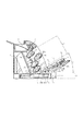
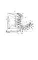
図2は、プロセスカートリッジAa〜Adの交換等のための着脱と用紙カセット11の用紙供給等のための着脱を示す図であり、搬送ベルト2や駆動ローラ3a、従動ローラ3bを保持するドアBを開くことでプロセスカートリッジAa〜Adにアクセス可能となり、プロセスカートリッジAa〜Adは着脱可能となる。
FIG. 2 is a view showing attachment / detachment for replacement of process cartridges Aa to Ad and attachment / detachment for paper supply of the
図2に示される様に、プロセスカートリッジAa〜Adは斜め上方(H方向)に引き抜かれ、用紙カセット11は実質的に水平方向(J方向)に引き抜かれる。つまりプロセスカートリッジAa〜Adの着脱と用紙カセット11の着脱は装置本体の同一面側から行われ、プロセスカートリッジAa〜Adの着脱方向と用紙カセット11の着脱方向は異なる。
As shown in FIG. 2, the process cartridges Aa to Ad are pulled out obliquely upward (H direction), and the
ここで、本実施例では、図1に示す様に、ベルト面Tが上下斜め方向、つまり鉛直方向に対して傾いて配置されている。ベルト面Tの傾きの方向は、下から上に向かってベルト面Tがプロセスカートリッジ側に倒れた方向である。従って、プロセスカートリッジAa〜Adも斜め方向に、感光体ドラム1a〜1dを上方に向けて並んでいる。つまり、複数のプロセスカートリッジAa〜Adの配列方向は、鉛直方向に対して傾いており、複数のプロセスカートリッジAa〜Adの上側のカートリッジ(例えばAc)は、下側のカートリッジ(例えばAd)よりドアBとは反対側に位置している。 Here, in this embodiment, as shown in FIG. 1, the belt surface T is arranged to be inclined with respect to the up and down diagonal direction, that is, the vertical direction. The direction of the inclination of the belt surface T is a direction in which the belt surface T falls to the process cartridge side from the bottom to the top. Accordingly, the process cartridges Aa to Ad are also arranged in the oblique direction with the photosensitive drums 1a to 1d facing upward. That is, the arrangement direction of the plurality of process cartridges Aa to Ad is inclined with respect to the vertical direction, and the upper cartridge (for example, Ac) of the plurality of process cartridges Aa to Ad is a door from the lower cartridge (for example, Ad). It is located on the opposite side of B.
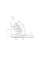
図3はプロセスカートリッジ及び用紙カセット11を着脱する際のガイドについて説明する概略図である。Ga、Gb、Gc、Gdはそれぞれ、プロセスカートリッジAa〜Adの移動を案内するカートリッジガイド部材であり、このガイド部材Ga〜Gdに沿ってプロセスカートリッジAa〜AdをH方向に移動することで、プロセスカートリッジAa〜Adは装置本体に対して着脱される。又、11aは用紙カセット11に設けられた係合突部、11bは係合突部11aと係合し用紙カセット11の移動を案内するカセットガイド部材であり、このガイド部材11bに沿って用紙カセット11をJ方向に移動することで、用紙カセット11は装置本体に対して着脱される。用紙カセット11の着脱は、ドアBの下方で行われ、その着脱方向Jは本実施例では実質的に水平方向である。つまり本実施例では、プロセスカートリッジAa〜Adの着脱方向Hと用紙カセット11の着脱方向Jは異なる。
FIG. 3 is a schematic diagram for explaining a guide when the process cartridge and the
尚、KはプロセスカートリッジAa〜Adの配列方向であり、本実施例ではプロセスカートリッジAa〜Adの着脱方向Hと実質的に直交する方向となっている。 Incidentally, K is the arrangement direction of the process cartridges Aa to Ad. In this embodiment, K is a direction substantially perpendicular to the attaching / detaching direction H of the process cartridges Aa to Ad.
このように本実施例では、プロセスカートリッジAa〜Adの着脱方向を用紙カセット11の着脱方向に対し斜めにすることで、プロセスカートリッジAa〜Adの着脱軌跡を図2のCの領域、つまりドアB及び用紙カセット11の上方で斜め方向に平行に伸びた領域とし、水平方向である下方に位置する用紙カセット11の着脱軌跡である領域Dとの間に、領域Eを確保し、そして、この領域Dに開放状態のドアBを位置決めして固定配置した。
As described above, in this embodiment, the attachment / detachment direction of the process cartridges Aa to Ad is inclined with respect to the attachment / detachment direction of the
これにより、本実施例では、装置全体の高さを抑えつつ、プロセスカートリッジAa〜Adと用紙カセット11を同時に着脱することができ、操作性が向上した。
Thus, in this embodiment, the process cartridges Aa to Ad and the
又、本実施例では、プロセスカートリッジAa〜Adの着脱方向だけでなく、配列方向も傾いているので、上側のプロセスカートリッジに干渉することなく下側のプロセスカートリッジを着脱することができ、プロセスカートリッジの形状等に制約を受けることが無い。 In this embodiment, not only the direction of attaching / detaching the process cartridges Aa to Ad but also the arrangement direction is inclined, so that the lower process cartridge can be attached / detached without interfering with the upper process cartridge. There are no restrictions on the shape and the like.
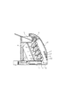
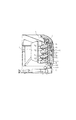
図4及び5は、ドアBを開放した時にドアBを位置決めする位置決め手段について説明するための図である。 4 and 5 are diagrams for explaining positioning means for positioning the door B when the door B is opened.
21はドアBに設けられた回転軸(突部)、23は装置本体側に設けられた係合突部、22は回転軸21の回りに回転可能で、係合突部が係合可能な長穴を有する係合部材である。これら回転軸21、係合突部23、係合部材22により、ドアBの開放状態における位置決め手段が構成される。
21 is a rotation shaft (projection) provided on the door B, 23 is an engagement projection provided on the apparatus body side, 22 is rotatable around the
つまり図4の状態から図5の状態の様にドアBを開くと、回転軸21の移動と共に係合部材22が移動し、係合部材22の長穴の端部が係合突部23と接触して係合部材22の移動が禁止されると、ドアBはその位置で固定され、ドアBの位置決めが行われる。
That is, when the door B is opened from the state of FIG. 4 as in the state of FIG. 5, the
ここで、比較例として、図6及び7に示す画像形成装置について説明する。図6に示す画像形成装置は、図1に示した本発明の実施例と構成要素は同一であるが、カートリッジLa、Lb、Lc、Ldの感光体ドラム1a〜1dと搬送ベルト24で構成される用紙搬送経路が斜めに傾いておらず、鉛直方向となっている。
Here, as a comparative example, the image forming apparatus shown in FIGS. 6 and 7 will be described. The image forming apparatus shown in FIG. 6 has the same components as the embodiment of the present invention shown in FIG. 1, but is composed of the photosensitive drums 1a to 1d of the cartridges La, Lb, Lc, and Ld and the
この比較例では、図7に示すように、最上部のカートリッジLaは、ここでは、定着器5が上方に存在することになるため斜め方向に着脱不能となる。これを解決するためには、カートリッジLa〜Ldの着脱方向を水平方向Nにしなければならない。このとき図2と同様に用紙カセット11を水平方向Jに着脱可能なように、ドアMの開き角を規定すると、最下部のカートリッジLdはドアMと接触してしまい着脱ができなくなってしまう。このカートリッジLdを着脱するためには、ドアMを少なくとも90°以上、ベルト24が水平になるくらいまでドアMを回転させなければならず、そうすると今度は用紙カセットが着脱できなくなる。
In this comparative example, as shown in FIG. 7, the uppermost cartridge La is not attachable / detachable in an oblique direction because the fixing device 5 exists above. In order to solve this, the attaching / detaching direction of the cartridges La to Ld must be the horizontal direction N. At this time, if the opening angle of the door M is defined so that the
従って比較例では、ドアMをある開放位置に固定した状態で、カートリッジLa〜Ldの着脱と用紙カセットの着脱を同時に行うことはできない。 Therefore, in the comparative example, the cartridges La to Ld and the paper cassette cannot be attached and detached simultaneously with the door M fixed at a certain open position.
又、ドアMのベルト24が水平になるまで開放しても、用紙カセット11が着脱できるように用紙カセット11とカートリッジLdの間を広げることが、またカートリッジLaと定着器5の間を広げてカートリッジLaが斜めに着脱できるようにすることが考えられるが、いずれも画像形成装置の高さが高くなり、装置が大型化するため好ましくない。
Even if the
依って、本実施例では、プロセスカートリッジAa〜Adの着脱方向を用紙カセット11の着脱方向に対し斜めにすることで、着脱軌跡を図2のCの領域とし、用紙カセット11の着脱軌跡Dとの間に空間Eを確保し、ここに開放状態のドアBを配置することで、プロセスカートリッジAa〜Adと用紙カセット11を同時に着脱可能であり、操作性の向上を図ることができる。また、ドアの開閉、プロセスカートリッジの着脱、用紙カセットの着脱は全て、装置本体に対して同一方向から操作することができ、更に操作性を向上することができる。
Therefore, in this embodiment, the attachment / detachment direction of the process cartridges Aa to Ad is inclined with respect to the attachment / detachment direction of the
そして、更に、用紙搬送経路を斜めにすることによりさらに装置の小型化が可能となる。 Further, the apparatus can be further miniaturized by making the sheet conveyance path oblique.
尚、本実施例では、プロセスカートリッジと用紙カセットを同時に着脱可能と言っているが、これは開放状態のドアを更に動かすことなく、プロセスカートリッジと用紙カセットの両方にアクセスすることができることを意味するものである。 In this embodiment, the process cartridge and the paper cassette are said to be detachable at the same time, but this means that both the process cartridge and the paper cassette can be accessed without further moving the opened door. Is.
又、本実施例では、用紙カセットの着脱方向を水平方向としたが、必ずしもこれに限定されるものではない。 In this embodiment, the paper cassette is attached or detached in the horizontal direction, but the present invention is not necessarily limited to this.
又、本実施例においては、プロセスカートリッジを4つ用いるフルカラープリンタとしたが、プロセスカートリッジを1つのみ使うモノクロプリンタでも同様に構成可能であり、搬送ベルトについても搬送ローラ等で構成しても同様の効果を得ることができる。 In this embodiment, a full-color printer using four process cartridges is used. However, a monochrome printer using only one process cartridge can be configured in the same manner, and the transport belt can be configured by transport rollers or the like. The effect of can be obtained.
又、本実施例では、感光体ドラムと対向して移動する搬送部材としては、記録材を搬送する搬送ベルトとしたが、搬送部材はトナー像を担持搬送する中間転写体(中間転写ベルト)でもよく、図8に示すような、像担持体1から中間転写体30にトナー像を転写して複数のトナー像を一旦中間転写体に担持させ、中間転写体から記録材Sに一括してトナー像を転写する中間転写方式の画像形成装置においても適用可能である。 In this embodiment, the conveying member that moves facing the photosensitive drum is a conveying belt that conveys a recording material. However, the conveying member may be an intermediate transfer member (intermediate transfer belt) that carries and conveys a toner image. As shown in FIG. 8, the toner image is transferred from the image carrier 1 to the intermediate transfer member 30 to temporarily carry a plurality of toner images on the intermediate transfer member, and the toner is collectively transferred from the intermediate transfer member to the recording material S. The present invention is also applicable to an intermediate transfer type image forming apparatus that transfers an image.
上述した画像形成装置の構成部品の寸法、材質、形状、及びその相対位置などは、特に特定的な記載がない限りは、この発明の範囲をそれらのみに限定する趣旨のものではない。 The dimensions, materials, shapes, relative positions, and the like of the components of the image forming apparatus described above are not intended to limit the scope of the present invention only to those unless otherwise specified.
以上、本発明の実施例について説明したが、本発明は上記実施例に何ら限定されるものではなく、本発明の技術思想内であらゆる変形が可能である。 As mentioned above, although the Example of this invention was described, this invention is not limited to the said Example at all, All the deformation | transformation are possible within the technical thought of this invention.
Aa〜Ad プロセスカートリッジ
B ドア
C カートリッジ着脱領域(軌跡)
D 用紙カセット着脱領域(軌跡)
E ドア位置決め用空間
11 用紙カセット
21 回転軸
22 係合部材
23 係合突部
Aa to Ad Process cartridge B Door C Cartridge attachment / detachment area (trajectory)
D Paper cassette attachment / detachment area (trajectory)
E
Claims (7)
前記開閉部材を回転可能に支持する支持部材と、
前記開閉部材を開放した状態の時、装置本体に対して着脱可能な複数のカートリッジと、
前記開閉部材に保持され、前記開閉部材を閉じた状態の時に前記複数のカートリッジに対向し、前記開閉部材に連動して装置本体に対して開閉可能なベルトユニットと、
記録材を収容し装置本体に対して着脱可能な記録材収容手段と、
開放状態にある前記開閉部材を位置決めする位置決め手段と、
を有し、前記複数のカートリッジの各々は、感光体と感光体に作用する少なくとも一つの画像形成部材とを一体的に備え、前記複数のカートリッジは、上下方向に並び、且つ記録材収容手段の上方に設けられており、前記複数のカートリッジの着脱と前記記録材収容手段の着脱は装置本体の同一面側から行われる画像形成装置において、
前記複数のカートリッジの着脱を案内するガイド部材を有し、
前記位置決め手段は、前記複数のカートリッジの着脱軌跡と前記記録材収容手段の着脱軌跡との間に形成される空間に、前記開閉部材及び前記ベルトユニットが位置するよう、前記開閉部材を位置決めし、
前記開閉部材及び前記ベルトユニットが、前記複数のカートリッジの着脱軌跡と前記記録材収容手段の着脱軌跡との間に形成される空間に位置した状態で、前記複数のカートリッジは前記ガイド部材に案内されて斜め上方に引き抜き可能で、且つ、前記記録材収容手段は実質的に水平に引き抜き可能であることを特徴とする画像形成装置。 An opening and closing member that can be opened and closed with respect to the apparatus body;
A support member that rotatably supports the opening and closing member ;
A plurality of cartridges that can be attached to and detached from the apparatus main body when the opening and closing member is opened;
A belt unit that is held by the opening and closing member, faces the plurality of cartridges when the opening and closing member is closed, and can be opened and closed with respect to the apparatus main body in conjunction with the opening and closing member;
Recording material storage means for storing the recording material and detachable from the apparatus main body;
Positioning means for positioning the open / close member in an open state;
Each of the plurality of cartridges integrally includes a photosensitive member and at least one image forming member acting on the photosensitive member, and the plurality of cartridges are arranged in a vertical direction and are arranged in a recording material storage unit. In the image forming apparatus provided above, the attachment and detachment of the plurality of cartridges and the attachment and detachment of the recording material storage means are performed from the same surface side of the apparatus main body.
A guide member for guiding attachment and detachment of the plurality of cartridges ;
It said positioning means, the space formed between the detachable trajectory of the detachable trajectory of the plurality of cartridges the recording material accommodating means, such that the closing member and the belt unit is located, and positions the closing member,
The plurality of cartridges are guided by the guide member in a state where the opening / closing member and the belt unit are located in a space formed between the attachment / detachment locus of the plurality of cartridges and the attachment / detachment locus of the recording material accommodation unit. Te can pull obliquely upwards, and the recording material accommodating means is an image forming apparatus according to claim available der Rukoto pulling substantially horizontally.
前記ガイド部材が前記複数のカートリッジの着脱を案内する方向は、前記開閉部材が前記位置決め手段によって位置決めされた状態における前記ベルトユニットのベルト面と平行であることを特徴とする請求項1乃至6のいずれか一項に記載の画像形成装置。7. The direction in which the guide member guides attachment / detachment of the plurality of cartridges is parallel to a belt surface of the belt unit in a state where the opening / closing member is positioned by the positioning means. The image forming apparatus according to claim 1.
Priority Applications (5)
| Application Number | Priority Date | Filing Date | Title |
|---|---|---|---|
| JP2005026529A JP4717455B2 (en) | 2004-02-27 | 2005-02-02 | Image forming apparatus |
| EP05004083.1A EP1569050B1 (en) | 2004-02-27 | 2005-02-24 | Color image forming apparatus with door comprising a sheet transport belt |
| US11/063,642 US7130560B2 (en) | 2004-02-27 | 2005-02-24 | Image forming apparatus |
| KR1020050015626A KR20060042194A (en) | 2004-02-27 | 2005-02-25 | Image forming apparatus |
| CNB2005100087400A CN100390682C (en) | 2004-02-27 | 2005-02-25 | Image forming apparatus |
Applications Claiming Priority (3)
| Application Number | Priority Date | Filing Date | Title |
|---|---|---|---|
| JP2004054332 | 2004-02-27 | ||
| JP2004054332 | 2004-02-27 | ||
| JP2005026529A JP4717455B2 (en) | 2004-02-27 | 2005-02-02 | Image forming apparatus |
Publications (3)
| Publication Number | Publication Date |
|---|---|
| JP2005275374A JP2005275374A (en) | 2005-10-06 |
| JP2005275374A5 JP2005275374A5 (en) | 2008-02-21 |
| JP4717455B2 true JP4717455B2 (en) | 2011-07-06 |
Family
ID=34752176
Family Applications (1)
| Application Number | Title | Priority Date | Filing Date |
|---|---|---|---|
| JP2005026529A Expired - Fee Related JP4717455B2 (en) | 2004-02-27 | 2005-02-02 | Image forming apparatus |
Country Status (5)
| Country | Link |
|---|---|
| US (1) | US7130560B2 (en) |
| EP (1) | EP1569050B1 (en) |
| JP (1) | JP4717455B2 (en) |
| KR (1) | KR20060042194A (en) |
| CN (1) | CN100390682C (en) |
Families Citing this family (23)
| Publication number | Priority date | Publication date | Assignee | Title |
|---|---|---|---|---|
| JP3870919B2 (en) * | 2003-03-20 | 2007-01-24 | ブラザー工業株式会社 | Image forming apparatus |
| JP2006036432A (en) * | 2004-07-26 | 2006-02-09 | Oki Data Corp | Image forming device |
| JP4630688B2 (en) * | 2004-08-30 | 2011-02-09 | キヤノン株式会社 | Development device |
| JP4658650B2 (en) * | 2005-03-17 | 2011-03-23 | ブラザー工業株式会社 | Image forming apparatus |
| JP4417281B2 (en) * | 2005-03-18 | 2010-02-17 | ブラザー工業株式会社 | Image forming apparatus |
| JP4850427B2 (en) * | 2005-03-28 | 2012-01-11 | キヤノン株式会社 | Process cartridge and electrophotographic image forming apparatus |
| JP2007163741A (en) * | 2005-12-13 | 2007-06-28 | Fuji Xerox Co Ltd | Image forming apparatus |
| JP4378374B2 (en) * | 2006-03-10 | 2009-12-02 | キヤノン株式会社 | Process cartridge, developer supply cartridge, and electrophotographic image forming apparatus |
| JP4883353B2 (en) * | 2006-09-08 | 2012-02-22 | 富士ゼロックス株式会社 | Image forming apparatus |
| KR101346164B1 (en) | 2007-01-26 | 2013-12-31 | 삼성전자주식회사 | Locking apparatus and image forming apparatus |
| KR101273593B1 (en) * | 2007-02-01 | 2013-06-11 | 삼성전자주식회사 | Image forming apparatus and method of feeding printing medium |
| JP5034609B2 (en) | 2007-03-30 | 2012-09-26 | 富士ゼロックス株式会社 | Image forming apparatus |
| JP5159176B2 (en) * | 2007-06-15 | 2013-03-06 | キヤノン株式会社 | Image forming apparatus |
| JP5159225B2 (en) * | 2007-09-21 | 2013-03-06 | キヤノン株式会社 | Image forming apparatus |
| US20090083128A1 (en) * | 2007-09-24 | 2009-03-26 | Introspective Solutions, Llc | Predicted variable analysis based on evaluation variables relating to site selection |
| JP5004870B2 (en) * | 2008-05-23 | 2012-08-22 | キヤノン株式会社 | Process cartridge and electrophotographic image forming apparatus |
| JP5127565B2 (en) * | 2008-05-23 | 2013-01-23 | キヤノン株式会社 | Cartridge and image forming apparatus |
| JP4592113B2 (en) * | 2009-03-02 | 2010-12-01 | キヤノン株式会社 | Color electrophotographic image forming apparatus |
| JP5762054B2 (en) * | 2010-03-16 | 2015-08-12 | キヤノン株式会社 | Process cartridge and image forming apparatus |
| JP5839826B2 (en) | 2011-04-22 | 2016-01-06 | キヤノン株式会社 | Development device reproduction method, process cartridge reproduction method, development device, and process cartridge |
| JP5460824B2 (en) | 2011-12-09 | 2014-04-02 | キヤノン株式会社 | cartridge |
| ES2932091T3 (en) | 2017-12-13 | 2023-01-11 | Canon Kk | Cartridge and Imaging Device |
| CN116339092A (en) | 2020-12-07 | 2023-06-27 | 佳能株式会社 | Toner container and image forming system |
Citations (4)
| Publication number | Priority date | Publication date | Assignee | Title |
|---|---|---|---|---|
| JP2001356548A (en) * | 2000-06-14 | 2001-12-26 | Brother Ind Ltd | Color image forming device |
| JP2003167412A (en) * | 2001-12-03 | 2003-06-13 | Seiko Epson Corp | Image forming apparatus |
| JP2003276276A (en) * | 2002-03-27 | 2003-09-30 | Brother Ind Ltd | Imaging apparatus |
| JP2003280407A (en) * | 2003-04-21 | 2003-10-02 | Ricoh Co Ltd | Image forming apparatus |
Family Cites Families (47)
| Publication number | Priority date | Publication date | Assignee | Title |
|---|---|---|---|---|
| US185984A (en) * | 1877-01-02 | Improvement in heating box-irons | ||
| US142994A (en) * | 1873-09-23 | Improvement in sash-holders | ||
| US156848A (en) * | 1874-11-17 | Improvement in machines for burnishing boot and shoe heels | ||
| US156856A (en) * | 1874-11-17 | Improvement in saw-filing benches | ||
| US5169A (en) * | 1847-06-19 | Straw-cutter | ||
| US649188A (en) * | 1899-03-31 | 1900-05-08 | Henry Herman Westinghouse | Draw-gear and buffing apparatus. |
| DE68920781T2 (en) | 1988-06-17 | 1995-06-14 | Canon Kk | Image recorder. |
| GB2238758B (en) | 1989-12-06 | 1994-01-12 | Ricoh Kk | Image recording apparatus constituting of selectable units |
| JPH0484166A (en) * | 1990-07-26 | 1992-03-17 | Konica Corp | Image forming device |
| JPH06110262A (en) | 1992-09-28 | 1994-04-22 | Fujitsu Ltd | Image forming device |
| JPH06250450A (en) | 1993-02-23 | 1994-09-09 | Konica Corp | Color image forming device |
| JP3273271B2 (en) | 1993-03-18 | 2002-04-08 | コニカ株式会社 | Color image forming equipment |
| US5444515A (en) | 1993-02-23 | 1995-08-22 | Konica Corporation | Color image forming apparatus with mountable cartridge therein |
| JPH0822157A (en) | 1994-07-07 | 1996-01-23 | Ricoh Co Ltd | Electrophotographic device |
| JPH08115042A (en) | 1994-10-18 | 1996-05-07 | Canon Inc | Image forming device |
| JPH08254862A (en) | 1995-03-15 | 1996-10-01 | Fujitsu Ltd | Image forming device |
| JP2875203B2 (en) | 1995-03-27 | 1999-03-31 | キヤノン株式会社 | Electrophotographic image forming apparatus, process cartridge, driving force transmitting component, and electrophotographic photosensitive drum |
| US5887228A (en) * | 1995-10-16 | 1999-03-23 | Ricoh Company, Ltd. | Color image forming apparatus including process cartridge |
| US6226478B1 (en) | 1996-03-21 | 2001-05-01 | Canon Kabushiki Kaisha | Process cartridge having drive mount for photosensitive drum |
| US6240266B1 (en) | 1996-03-21 | 2001-05-29 | Canon Kabushiki Kaisha | Process cartridge and drum mount for photosensitive drum |
| JP3809250B2 (en) | 1996-07-04 | 2006-08-16 | キヤノン株式会社 | Support component, developer container, process cartridge, and electrophotographic image forming apparatus |
| JPH1069199A (en) | 1996-08-29 | 1998-03-10 | Canon Inc | Cleaner, process cartridge, electrophotographic image forming device, and cleaning frame |
| JP3745047B2 (en) | 1996-09-26 | 2006-02-15 | キヤノン株式会社 | Electrophotographic image forming apparatus and process cartridge |
| JP3745049B2 (en) | 1996-09-26 | 2006-02-15 | キヤノン株式会社 | Process cartridge and electrophotographic image forming apparatus |
| US6175706B1 (en) | 1996-09-26 | 2001-01-16 | Canon Kabushiki Kaisha | Process cartridge, electrophotographic image forming apparatus driving force transmission part and electrophotographic photosensitive drum |
| JP3658202B2 (en) | 1998-08-31 | 2005-06-08 | キヤノン株式会社 | Developing cartridge assembly method |
| JP3338023B2 (en) | 1999-09-27 | 2002-10-28 | キヤノン株式会社 | Process cartridge, handle mounting method, and electrophotographic image forming apparatus |
| JP3338024B2 (en) | 1999-09-27 | 2002-10-28 | キヤノン株式会社 | Handle, process cartridge, handle mounting method, and electrophotographic image forming apparatus |
| JP2001249601A (en) * | 2000-03-03 | 2001-09-14 | Canon Inc | Image forming device |
| JP2001281996A (en) | 2000-04-03 | 2001-10-10 | Canon Inc | Developing cartridge, processing cartridge and electrophotographic image forming device |
| US6798430B2 (en) | 2000-06-14 | 2004-09-28 | Brother Kogyo Kabushiki Kaisha | Tandem type color image forming device having a plurality of process cartridges arrayed in running direction of intermediate image transfer member |
| JP2001356550A (en) | 2000-06-16 | 2001-12-26 | Brother Ind Ltd | Color image forming device |
| JP2002006609A (en) | 2000-06-26 | 2002-01-11 | Canon Inc | Toner sealing member, developing cartridge, process cartridge and electrophotographic image forming device |
| JP2002023476A (en) | 2000-07-07 | 2002-01-23 | Canon Inc | Developing cartridge, process cartridge and electrophotographic image forming device |
| JP2002193497A (en) * | 2000-10-20 | 2002-07-10 | Ricoh Co Ltd | Paper feeder and image forming device provided with this paper feeder |
| JP3652246B2 (en) | 2000-12-21 | 2005-05-25 | キヤノン株式会社 | Process cartridge and image forming apparatus |
| JP4125007B2 (en) | 2002-01-11 | 2008-07-23 | キヤノン株式会社 | Process cartridge and electrophotographic image forming apparatus |
| JP3586675B2 (en) | 2002-02-08 | 2004-11-10 | 株式会社リコー | Image forming device |
| EP1331525A3 (en) | 2002-01-25 | 2004-06-23 | Ricoh Company, Ltd. | Image forming apparatus with improved image quality and maintenance workability |
| JP3595798B2 (en) * | 2002-01-31 | 2004-12-02 | キヤノン株式会社 | Process cartridge and electrophotographic image forming apparatus |
| JP3634807B2 (en) | 2002-02-20 | 2005-03-30 | キヤノン株式会社 | Process cartridge and image forming apparatus |
| JP2003241616A (en) * | 2002-02-21 | 2003-08-29 | Canon Inc | Image forming device |
| JP3658372B2 (en) | 2002-02-22 | 2005-06-08 | キヤノン株式会社 | Process cartridge and separation holding member for process cartridge |
| JP4174380B2 (en) | 2002-07-04 | 2008-10-29 | キヤノン株式会社 | Electrophotographic photosensitive drum and process cartridge |
| CN2682454Y (en) | 2002-07-26 | 2005-03-02 | 精工爱普生株式会社 | Image forming device comprising transfer printing band |
| KR100547128B1 (en) * | 2003-07-04 | 2006-01-26 | 삼성전자주식회사 | Electrophotographic printer |
| JP3673793B2 (en) * | 2003-08-29 | 2005-07-20 | キヤノン株式会社 | Process cartridge, process cartridge mounting mechanism, and electrophotographic image forming apparatus |
-
2005
- 2005-02-02 JP JP2005026529A patent/JP4717455B2/en not_active Expired - Fee Related
- 2005-02-24 US US11/063,642 patent/US7130560B2/en active Active
- 2005-02-24 EP EP05004083.1A patent/EP1569050B1/en not_active Expired - Fee Related
- 2005-02-25 CN CNB2005100087400A patent/CN100390682C/en not_active Expired - Fee Related
- 2005-02-25 KR KR1020050015626A patent/KR20060042194A/en active Search and Examination
Patent Citations (4)
| Publication number | Priority date | Publication date | Assignee | Title |
|---|---|---|---|---|
| JP2001356548A (en) * | 2000-06-14 | 2001-12-26 | Brother Ind Ltd | Color image forming device |
| JP2003167412A (en) * | 2001-12-03 | 2003-06-13 | Seiko Epson Corp | Image forming apparatus |
| JP2003276276A (en) * | 2002-03-27 | 2003-09-30 | Brother Ind Ltd | Imaging apparatus |
| JP2003280407A (en) * | 2003-04-21 | 2003-10-02 | Ricoh Co Ltd | Image forming apparatus |
Also Published As
| Publication number | Publication date |
|---|---|
| EP1569050A1 (en) | 2005-08-31 |
| US7130560B2 (en) | 2006-10-31 |
| JP2005275374A (en) | 2005-10-06 |
| EP1569050B1 (en) | 2014-06-18 |
| CN1661499A (en) | 2005-08-31 |
| US20050191086A1 (en) | 2005-09-01 |
| CN100390682C (en) | 2008-05-28 |
| KR20060042194A (en) | 2006-05-12 |
Similar Documents
| Publication | Publication Date | Title |
|---|---|---|
| JP4717455B2 (en) | Image forming apparatus | |
| JP5004870B2 (en) | Process cartridge and electrophotographic image forming apparatus | |
| KR101721013B1 (en) | Image forming apparatus | |
| JP5127565B2 (en) | Cartridge and image forming apparatus | |
| US10852687B2 (en) | Image forming apparatus | |
| JP4134985B2 (en) | Image forming apparatus and cartridge | |
| US8073360B2 (en) | Color electrophotographic image forming apparatus | |
| JP5159176B2 (en) | Image forming apparatus | |
| JP5067913B2 (en) | Process cartridge and electrophotographic image forming apparatus | |
| JP7027068B2 (en) | Image forming device | |
| JP2011048342A (en) | Color electrophotographic image forming apparatus and photosensitive member cartridge | |
| JP5167774B2 (en) | Image forming apparatus | |
| JP4835671B2 (en) | Image forming apparatus | |
| US10423093B2 (en) | Image forming apparatus | |
| JP2009181023A (en) | Image forming apparatus | |
| JP5523009B2 (en) | Image forming apparatus | |
| JP2018049198A (en) | Image forming apparatus and apparatus body | |
| JP5470892B2 (en) | Image forming apparatus | |
| JP5157298B2 (en) | Image forming apparatus | |
| JP5298964B2 (en) | Image forming apparatus | |
| JP2010002622A (en) | Image forming apparatus | |
| JP2006267843A (en) | Image forming apparatus | |
| US20060078350A1 (en) | Color image forming apparatus |
Legal Events
| Date | Code | Title | Description |
|---|---|---|---|
| A521 | Written amendment |
Free format text: JAPANESE INTERMEDIATE CODE: A523 Effective date: 20080108 |
|
| A621 | Written request for application examination |
Free format text: JAPANESE INTERMEDIATE CODE: A621 Effective date: 20080108 |
|
| RD04 | Notification of resignation of power of attorney |
Free format text: JAPANESE INTERMEDIATE CODE: A7424 Effective date: 20100201 |
|
| RD01 | Notification of change of attorney |
Free format text: JAPANESE INTERMEDIATE CODE: A7421 Effective date: 20100630 |
|
| A131 | Notification of reasons for refusal |
Free format text: JAPANESE INTERMEDIATE CODE: A131 Effective date: 20100907 |
|
| A977 | Report on retrieval |
Free format text: JAPANESE INTERMEDIATE CODE: A971007 Effective date: 20100907 |
|
| A521 | Written amendment |
Free format text: JAPANESE INTERMEDIATE CODE: A523 Effective date: 20101108 |
|
| A01 | Written decision to grant a patent or to grant a registration (utility model) |
Free format text: JAPANESE INTERMEDIATE CODE: A01 Effective date: 20110322 |
|
| A01 | Written decision to grant a patent or to grant a registration (utility model) |
Free format text: JAPANESE INTERMEDIATE CODE: A01 |
|
| A61 | First payment of annual fees (during grant procedure) |
Free format text: JAPANESE INTERMEDIATE CODE: A61 Effective date: 20110330 |
|
| R150 | Certificate of patent or registration of utility model |
Free format text: JAPANESE INTERMEDIATE CODE: R150 |
|
| FPAY | Renewal fee payment (event date is renewal date of database) |
Free format text: PAYMENT UNTIL: 20140408 Year of fee payment: 3 |
|
| LAPS | Cancellation because of no payment of annual fees |