JP4712959B2 - Load detection hydraulic controller for variable displacement pump - Google Patents
Load detection hydraulic controller for variable displacement pump Download PDFInfo
- Publication number
- JP4712959B2 JP4712959B2 JP2000348014A JP2000348014A JP4712959B2 JP 4712959 B2 JP4712959 B2 JP 4712959B2 JP 2000348014 A JP2000348014 A JP 2000348014A JP 2000348014 A JP2000348014 A JP 2000348014A JP 4712959 B2 JP4712959 B2 JP 4712959B2
- Authority
- JP
- Japan
- Prior art keywords
- signal
- valve
- pump
- controller
- pressure
- Prior art date
- Legal status (The legal status is an assumption and is not a legal conclusion. Google has not performed a legal analysis and makes no representation as to the accuracy of the status listed.)
- Expired - Fee Related
Links
Images

Classifications
-
- E—FIXED CONSTRUCTIONS
- E02—HYDRAULIC ENGINEERING; FOUNDATIONS; SOIL SHIFTING
- E02F—DREDGING; SOIL-SHIFTING
- E02F9/00—Component parts of dredgers or soil-shifting machines, not restricted to one of the kinds covered by groups E02F3/00 - E02F7/00
- E02F9/20—Drives; Control devices
- E02F9/22—Hydraulic or pneumatic drives
- E02F9/2217—Hydraulic or pneumatic drives with energy recovery arrangements, e.g. using accumulators, flywheels
-
- F—MECHANICAL ENGINEERING; LIGHTING; HEATING; WEAPONS; BLASTING
- F04—POSITIVE - DISPLACEMENT MACHINES FOR LIQUIDS; PUMPS FOR LIQUIDS OR ELASTIC FLUIDS
- F04B—POSITIVE-DISPLACEMENT MACHINES FOR LIQUIDS; PUMPS
- F04B49/00—Control, e.g. of pump delivery, or pump pressure of, or safety measures for, machines, pumps, or pumping installations, not otherwise provided for, or of interest apart from, groups F04B1/00 - F04B47/00
- F04B49/002—Hydraulic systems to change the pump delivery
-
- F—MECHANICAL ENGINEERING; LIGHTING; HEATING; WEAPONS; BLASTING
- F04—POSITIVE - DISPLACEMENT MACHINES FOR LIQUIDS; PUMPS FOR LIQUIDS OR ELASTIC FLUIDS
- F04B—POSITIVE-DISPLACEMENT MACHINES FOR LIQUIDS; PUMPS
- F04B49/00—Control, e.g. of pump delivery, or pump pressure of, or safety measures for, machines, pumps, or pumping installations, not otherwise provided for, or of interest apart from, groups F04B1/00 - F04B47/00
- F04B49/08—Regulating by delivery pressure
-
- F—MECHANICAL ENGINEERING; LIGHTING; HEATING; WEAPONS; BLASTING
- F15—FLUID-PRESSURE ACTUATORS; HYDRAULICS OR PNEUMATICS IN GENERAL
- F15B—SYSTEMS ACTING BY MEANS OF FLUIDS IN GENERAL; FLUID-PRESSURE ACTUATORS, e.g. SERVOMOTORS; DETAILS OF FLUID-PRESSURE SYSTEMS, NOT OTHERWISE PROVIDED FOR
- F15B11/00—Servomotor systems without provision for follow-up action; Circuits therefor
- F15B11/16—Servomotor systems without provision for follow-up action; Circuits therefor with two or more servomotors
- F15B11/161—Servomotor systems without provision for follow-up action; Circuits therefor with two or more servomotors with sensing of servomotor demand or load
- F15B11/165—Servomotor systems without provision for follow-up action; Circuits therefor with two or more servomotors with sensing of servomotor demand or load for adjusting the pump output or bypass in response to demand
-
- F—MECHANICAL ENGINEERING; LIGHTING; HEATING; WEAPONS; BLASTING
- F15—FLUID-PRESSURE ACTUATORS; HYDRAULICS OR PNEUMATICS IN GENERAL
- F15B—SYSTEMS ACTING BY MEANS OF FLUIDS IN GENERAL; FLUID-PRESSURE ACTUATORS, e.g. SERVOMOTORS; DETAILS OF FLUID-PRESSURE SYSTEMS, NOT OTHERWISE PROVIDED FOR
- F15B21/00—Common features of fluid actuator systems; Fluid-pressure actuator systems or details thereof, not covered by any other group of this subclass
- F15B21/08—Servomotor systems incorporating electrically operated control means
-
- F—MECHANICAL ENGINEERING; LIGHTING; HEATING; WEAPONS; BLASTING
- F04—POSITIVE - DISPLACEMENT MACHINES FOR LIQUIDS; PUMPS FOR LIQUIDS OR ELASTIC FLUIDS
- F04B—POSITIVE-DISPLACEMENT MACHINES FOR LIQUIDS; PUMPS
- F04B2205/00—Fluid parameters
- F04B2205/06—Pressure in a (hydraulic) circuit
- F04B2205/063—Pressure in a (hydraulic) circuit in a reservoir linked to the pump outlet
-
- F—MECHANICAL ENGINEERING; LIGHTING; HEATING; WEAPONS; BLASTING
- F15—FLUID-PRESSURE ACTUATORS; HYDRAULICS OR PNEUMATICS IN GENERAL
- F15B—SYSTEMS ACTING BY MEANS OF FLUIDS IN GENERAL; FLUID-PRESSURE ACTUATORS, e.g. SERVOMOTORS; DETAILS OF FLUID-PRESSURE SYSTEMS, NOT OTHERWISE PROVIDED FOR
- F15B2211/00—Circuits for servomotor systems
- F15B2211/20—Fluid pressure source, e.g. accumulator or variable axial piston pump
- F15B2211/205—Systems with pumps
- F15B2211/2053—Type of pump
- F15B2211/20546—Type of pump variable capacity
- F15B2211/20553—Type of pump variable capacity with pilot circuit, e.g. for controlling a swash plate
-
- F—MECHANICAL ENGINEERING; LIGHTING; HEATING; WEAPONS; BLASTING
- F15—FLUID-PRESSURE ACTUATORS; HYDRAULICS OR PNEUMATICS IN GENERAL
- F15B—SYSTEMS ACTING BY MEANS OF FLUIDS IN GENERAL; FLUID-PRESSURE ACTUATORS, e.g. SERVOMOTORS; DETAILS OF FLUID-PRESSURE SYSTEMS, NOT OTHERWISE PROVIDED FOR
- F15B2211/00—Circuits for servomotor systems
- F15B2211/20—Fluid pressure source, e.g. accumulator or variable axial piston pump
- F15B2211/205—Systems with pumps
- F15B2211/20576—Systems with pumps with multiple pumps
- F15B2211/20584—Combinations of pumps with high and low capacity
-
- F—MECHANICAL ENGINEERING; LIGHTING; HEATING; WEAPONS; BLASTING
- F15—FLUID-PRESSURE ACTUATORS; HYDRAULICS OR PNEUMATICS IN GENERAL
- F15B—SYSTEMS ACTING BY MEANS OF FLUIDS IN GENERAL; FLUID-PRESSURE ACTUATORS, e.g. SERVOMOTORS; DETAILS OF FLUID-PRESSURE SYSTEMS, NOT OTHERWISE PROVIDED FOR
- F15B2211/00—Circuits for servomotor systems
- F15B2211/20—Fluid pressure source, e.g. accumulator or variable axial piston pump
- F15B2211/21—Systems with pressure sources other than pumps, e.g. with a pyrotechnical charge
- F15B2211/212—Systems with pressure sources other than pumps, e.g. with a pyrotechnical charge the pressure sources being accumulators
-
- F—MECHANICAL ENGINEERING; LIGHTING; HEATING; WEAPONS; BLASTING
- F15—FLUID-PRESSURE ACTUATORS; HYDRAULICS OR PNEUMATICS IN GENERAL
- F15B—SYSTEMS ACTING BY MEANS OF FLUIDS IN GENERAL; FLUID-PRESSURE ACTUATORS, e.g. SERVOMOTORS; DETAILS OF FLUID-PRESSURE SYSTEMS, NOT OTHERWISE PROVIDED FOR
- F15B2211/00—Circuits for servomotor systems
- F15B2211/30—Directional control
- F15B2211/305—Directional control characterised by the type of valves
- F15B2211/30505—Non-return valves, i.e. check valves
-
- F—MECHANICAL ENGINEERING; LIGHTING; HEATING; WEAPONS; BLASTING
- F15—FLUID-PRESSURE ACTUATORS; HYDRAULICS OR PNEUMATICS IN GENERAL
- F15B—SYSTEMS ACTING BY MEANS OF FLUIDS IN GENERAL; FLUID-PRESSURE ACTUATORS, e.g. SERVOMOTORS; DETAILS OF FLUID-PRESSURE SYSTEMS, NOT OTHERWISE PROVIDED FOR
- F15B2211/00—Circuits for servomotor systems
- F15B2211/30—Directional control
- F15B2211/305—Directional control characterised by the type of valves
- F15B2211/3056—Assemblies of multiple valves
- F15B2211/30565—Assemblies of multiple valves having multiple valves for a single output member, e.g. for creating higher valve function by use of multiple valves like two 2/2-valves replacing a 5/3-valve
- F15B2211/30575—Assemblies of multiple valves having multiple valves for a single output member, e.g. for creating higher valve function by use of multiple valves like two 2/2-valves replacing a 5/3-valve in a Wheatstone Bridge arrangement (also half bridges)
-
- F—MECHANICAL ENGINEERING; LIGHTING; HEATING; WEAPONS; BLASTING
- F15—FLUID-PRESSURE ACTUATORS; HYDRAULICS OR PNEUMATICS IN GENERAL
- F15B—SYSTEMS ACTING BY MEANS OF FLUIDS IN GENERAL; FLUID-PRESSURE ACTUATORS, e.g. SERVOMOTORS; DETAILS OF FLUID-PRESSURE SYSTEMS, NOT OTHERWISE PROVIDED FOR
- F15B2211/00—Circuits for servomotor systems
- F15B2211/30—Directional control
- F15B2211/31—Directional control characterised by the positions of the valve element
- F15B2211/3105—Neutral or centre positions
- F15B2211/3111—Neutral or centre positions the pump port being closed in the centre position, e.g. so-called closed centre
-
- F—MECHANICAL ENGINEERING; LIGHTING; HEATING; WEAPONS; BLASTING
- F15—FLUID-PRESSURE ACTUATORS; HYDRAULICS OR PNEUMATICS IN GENERAL
- F15B—SYSTEMS ACTING BY MEANS OF FLUIDS IN GENERAL; FLUID-PRESSURE ACTUATORS, e.g. SERVOMOTORS; DETAILS OF FLUID-PRESSURE SYSTEMS, NOT OTHERWISE PROVIDED FOR
- F15B2211/00—Circuits for servomotor systems
- F15B2211/30—Directional control
- F15B2211/315—Directional control characterised by the connections of the valve or valves in the circuit
- F15B2211/3157—Directional control characterised by the connections of the valve or valves in the circuit being connected to a pressure source, an output member and a return line
- F15B2211/31576—Directional control characterised by the connections of the valve or valves in the circuit being connected to a pressure source, an output member and a return line having a single pressure source and a single output member
-
- F—MECHANICAL ENGINEERING; LIGHTING; HEATING; WEAPONS; BLASTING
- F15—FLUID-PRESSURE ACTUATORS; HYDRAULICS OR PNEUMATICS IN GENERAL
- F15B—SYSTEMS ACTING BY MEANS OF FLUIDS IN GENERAL; FLUID-PRESSURE ACTUATORS, e.g. SERVOMOTORS; DETAILS OF FLUID-PRESSURE SYSTEMS, NOT OTHERWISE PROVIDED FOR
- F15B2211/00—Circuits for servomotor systems
- F15B2211/30—Directional control
- F15B2211/32—Directional control characterised by the type of actuation
- F15B2211/327—Directional control characterised by the type of actuation electrically or electronically
-
- F—MECHANICAL ENGINEERING; LIGHTING; HEATING; WEAPONS; BLASTING
- F15—FLUID-PRESSURE ACTUATORS; HYDRAULICS OR PNEUMATICS IN GENERAL
- F15B—SYSTEMS ACTING BY MEANS OF FLUIDS IN GENERAL; FLUID-PRESSURE ACTUATORS, e.g. SERVOMOTORS; DETAILS OF FLUID-PRESSURE SYSTEMS, NOT OTHERWISE PROVIDED FOR
- F15B2211/00—Circuits for servomotor systems
- F15B2211/50—Pressure control
- F15B2211/505—Pressure control characterised by the type of pressure control means
- F15B2211/50509—Pressure control characterised by the type of pressure control means the pressure control means controlling a pressure upstream of the pressure control means
- F15B2211/50518—Pressure control characterised by the type of pressure control means the pressure control means controlling a pressure upstream of the pressure control means using pressure relief valves
-
- F—MECHANICAL ENGINEERING; LIGHTING; HEATING; WEAPONS; BLASTING
- F15—FLUID-PRESSURE ACTUATORS; HYDRAULICS OR PNEUMATICS IN GENERAL
- F15B—SYSTEMS ACTING BY MEANS OF FLUIDS IN GENERAL; FLUID-PRESSURE ACTUATORS, e.g. SERVOMOTORS; DETAILS OF FLUID-PRESSURE SYSTEMS, NOT OTHERWISE PROVIDED FOR
- F15B2211/00—Circuits for servomotor systems
- F15B2211/50—Pressure control
- F15B2211/515—Pressure control characterised by the connections of the pressure control means in the circuit
- F15B2211/5157—Pressure control characterised by the connections of the pressure control means in the circuit being connected to a pressure source and a return line
-
- F—MECHANICAL ENGINEERING; LIGHTING; HEATING; WEAPONS; BLASTING
- F15—FLUID-PRESSURE ACTUATORS; HYDRAULICS OR PNEUMATICS IN GENERAL
- F15B—SYSTEMS ACTING BY MEANS OF FLUIDS IN GENERAL; FLUID-PRESSURE ACTUATORS, e.g. SERVOMOTORS; DETAILS OF FLUID-PRESSURE SYSTEMS, NOT OTHERWISE PROVIDED FOR
- F15B2211/00—Circuits for servomotor systems
- F15B2211/50—Pressure control
- F15B2211/52—Pressure control characterised by the type of actuation
- F15B2211/528—Pressure control characterised by the type of actuation actuated by fluid pressure
-
- F—MECHANICAL ENGINEERING; LIGHTING; HEATING; WEAPONS; BLASTING
- F15—FLUID-PRESSURE ACTUATORS; HYDRAULICS OR PNEUMATICS IN GENERAL
- F15B—SYSTEMS ACTING BY MEANS OF FLUIDS IN GENERAL; FLUID-PRESSURE ACTUATORS, e.g. SERVOMOTORS; DETAILS OF FLUID-PRESSURE SYSTEMS, NOT OTHERWISE PROVIDED FOR
- F15B2211/00—Circuits for servomotor systems
- F15B2211/60—Circuit components or control therefor
- F15B2211/605—Load sensing circuits
- F15B2211/6051—Load sensing circuits having valve means between output member and the load sensing circuit
- F15B2211/6054—Load sensing circuits having valve means between output member and the load sensing circuit using shuttle valves
-
- F—MECHANICAL ENGINEERING; LIGHTING; HEATING; WEAPONS; BLASTING
- F15—FLUID-PRESSURE ACTUATORS; HYDRAULICS OR PNEUMATICS IN GENERAL
- F15B—SYSTEMS ACTING BY MEANS OF FLUIDS IN GENERAL; FLUID-PRESSURE ACTUATORS, e.g. SERVOMOTORS; DETAILS OF FLUID-PRESSURE SYSTEMS, NOT OTHERWISE PROVIDED FOR
- F15B2211/00—Circuits for servomotor systems
- F15B2211/60—Circuit components or control therefor
- F15B2211/625—Accumulators
-
- F—MECHANICAL ENGINEERING; LIGHTING; HEATING; WEAPONS; BLASTING
- F15—FLUID-PRESSURE ACTUATORS; HYDRAULICS OR PNEUMATICS IN GENERAL
- F15B—SYSTEMS ACTING BY MEANS OF FLUIDS IN GENERAL; FLUID-PRESSURE ACTUATORS, e.g. SERVOMOTORS; DETAILS OF FLUID-PRESSURE SYSTEMS, NOT OTHERWISE PROVIDED FOR
- F15B2211/00—Circuits for servomotor systems
- F15B2211/60—Circuit components or control therefor
- F15B2211/63—Electronic controllers
- F15B2211/6303—Electronic controllers using input signals
- F15B2211/6306—Electronic controllers using input signals representing a pressure
- F15B2211/6313—Electronic controllers using input signals representing a pressure the pressure being a load pressure
-
- F—MECHANICAL ENGINEERING; LIGHTING; HEATING; WEAPONS; BLASTING
- F15—FLUID-PRESSURE ACTUATORS; HYDRAULICS OR PNEUMATICS IN GENERAL
- F15B—SYSTEMS ACTING BY MEANS OF FLUIDS IN GENERAL; FLUID-PRESSURE ACTUATORS, e.g. SERVOMOTORS; DETAILS OF FLUID-PRESSURE SYSTEMS, NOT OTHERWISE PROVIDED FOR
- F15B2211/00—Circuits for servomotor systems
- F15B2211/60—Circuit components or control therefor
- F15B2211/63—Electronic controllers
- F15B2211/6303—Electronic controllers using input signals
- F15B2211/6346—Electronic controllers using input signals representing a state of input means, e.g. joystick position
-
- F—MECHANICAL ENGINEERING; LIGHTING; HEATING; WEAPONS; BLASTING
- F15—FLUID-PRESSURE ACTUATORS; HYDRAULICS OR PNEUMATICS IN GENERAL
- F15B—SYSTEMS ACTING BY MEANS OF FLUIDS IN GENERAL; FLUID-PRESSURE ACTUATORS, e.g. SERVOMOTORS; DETAILS OF FLUID-PRESSURE SYSTEMS, NOT OTHERWISE PROVIDED FOR
- F15B2211/00—Circuits for servomotor systems
- F15B2211/70—Output members, e.g. hydraulic motors or cylinders or control therefor
- F15B2211/705—Output members, e.g. hydraulic motors or cylinders or control therefor characterised by the type of output members or actuators
- F15B2211/7051—Linear output members
- F15B2211/7053—Double-acting output members
Landscapes
- Engineering & Computer Science (AREA)
- General Engineering & Computer Science (AREA)
- Mechanical Engineering (AREA)
- Physics & Mathematics (AREA)
- Fluid Mechanics (AREA)
- Chemical & Material Sciences (AREA)
- Analytical Chemistry (AREA)
- Mining & Mineral Resources (AREA)
- Civil Engineering (AREA)
- Structural Engineering (AREA)
- Fluid-Pressure Circuits (AREA)
- Control Of Positive-Displacement Pumps (AREA)
Description
【0001】
【発明の属する技術分野】
本発明は、一般的には荷重検知油圧装置(システム)に係り、より特別には可変容量ポンプに負荷圧力信号を伝達するために外部ネットワークを利用する荷重検知油圧装置に関する。
【0002】
【従来の技術】
作業(work)機械のオペレーションにおける制御性および効率の改善に関する要求は、荷重検知油圧装置の用途の増大に連結している。従来の油圧システムに比較して、ポンプ流量およびポンプ圧力が共に実負荷に連続的に一致するので、可変容量ポンプを具備する荷重検知油圧装置はより効率的である。荷重検知バルブシステムの形態は、従来の閉鎖中心(closed−center)及び開放中心(open−center)タイプのバルブ両者から導くことが可能であり、広い種類の異なるシステム形態が使用されている。異なるバルブ形態は異なるオペレーション特性を生じる。使用される特定のバルブの形態に関係なく、実際の荷重を表示していて、特別な荷重検知バルブ機構を使用しないで、ポンプコントローラ(制御装置)に伝送可能な荷重信号を生成することは常に難しい。ポンプコントローラとの通信のために真の高圧の荷重検知信号を、それに関係する高圧発生源を有しないで、複写することはやはり困難である。
【0003】
【発明が解決しようとする課題】
従って可変容量油圧ポンプのポンプコントローラに荷重検知信号を、そのような信号を機械的に制御するために特別な接続口または別の特別なバルブ手段を使用しないで、且つこの役割を実施するために主制御弁ネットワーク内で圧力補償均衡バルブ等の機構を使用しないで、提供することが要望されている。更に高圧の荷重信号を、油圧装置に作用する実際の荷重を表す所定のより低圧の荷重信号に減少またはスケールダウンするための機構を提供することが望まれる。
従って本発明は上記された1つ以上の問題を克服することを目的とする。
【0004】
【課題を解決するための手段】
本発明は、可変容量ポンプの容量を制御するための荷重検知油圧制御装置に係わり、そこでは作業(work)要素又は作業付属品の動きを制御するために使用される作動シリンダに対して作用する実際の負荷又は圧力が圧力送信器(transducer)又は別のセンサ手段により検知されており、実際のシリンダ荷重を表す信号は電気制御装置又は別の処理手段に伝送される。電気制御装置は電気油圧弁への実際のシリンダ荷重を表す信号を出力するように運転可能であり、その電気油圧弁は所定の荷重信号を可変容量油圧ポンプに伝送するための信号複写弁として作用して、ポンプ容量を連続的に調整してポンプ流量及びポンプ圧力を実際のシリンダ負荷に一致するように制御する。本発明の1つの形態においてチャージバルブは、ポンプに対する最小のポンプ出力流量及び圧力を形成するように使用され、アキュミュレータは、ポンプコントローラへの人工の荷重信号を生成するために加圧された流体の発生源を提供するように使用される。本発明のこれとは別の形態において、前もって決められた圧力で稼働するパイロットポンプが、望まれる人工の荷重信号をポンプコントローラに提供するように使用される。
【0005】
本荷重検知装置は複数の比例弁、標準三位置形弁、スプリットスプールタイプバルブ、及び荷重検知性能が必要な特定の役割を実施するための適当なアクチュエータ、モータ又は別の装置に連結された別の作動弁等の多種類の異なるタイプの主制御弁により利用されることが可能である。本装置は、主制御弁ネットワークの外側に荷重検知能力を具備しており、その検知能力の設計はより安価であり、それはより少ない複雑な構成要素を具備しており、それはポンプの摩耗及び破損(tear)を減少し、更にそれはポンプ性能を実際のシリンダ負荷に適合するための別個の発生源を提供する。
【0006】
【発明の実施の形態】
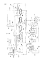
図1を参照すると、荷重検知油圧ポンプ圧力制御装置(システム)10が、吐出管路(passage)18を介してタンク14及び油圧シリンダ又は別の作業(work)要素16に流体的に連絡する可変容量ポンプ12と組み合わせた状態で図示される。油圧ポンプ12は、容量制御要素22に接続するポンプ容量コントローラ20を具備しており、ポンプコントローラ20は流体経路24を経由して荷重検知信号を受信して、容量制御要素22を調整して、荷重検知信号に対応して作動(actuating)シリンダ16に所定の流体圧力を実現し更に維持する。ポンプ12及びその関係するコントローラ20は、含まれる特定の装置の用途に依存する多種類の異なる形態を具備することが可能であり、コントローラ20はばね又は容量制御要素22をその最大又は最小のいずれかの容量設定に弾性的に押しつける何か別の押しつけ機構を具備してもよい。ポンプ12は、吐出管路18を介して所定の流体の流れを実現するために、流体経路24を経由して受信された荷重検知信号に応じて容量制御要素22を調整する。
【0007】
図1に示される実施の形態において、作動シリンダ16のオペレーションを制御するための主制御弁機構26は、4基の別個の比例式電気油圧弁28、30、32と34を具備しており、それら前記の弁は電気制御装置又は処理装置38からの信号入力に基づいて増加的に作動シリンダ16を駆動する。各弁28、30、32と34は、特定の作業機械に関係する一以上の制御レバー又はジョイスティック等のオペレータ制御機構40を介して処理装置38へ入力されるオペレータ指令に基づいて、処理装置又は制御装置38を介して電気的に制御される。オペレータ入力装置40の動きは、適切な信号を導電性経路(パス)42を介して制御装置38へ出力しており、その様な入力信号42に基づいて制御装置38は、導電性パス44、46,48と50を経由してそれらとそれぞれ関係するソレノイド又は別の電気アクチュエータ手段52、54、56と58に適切な信号を出力することにより、比例式弁28、30、32と34のオペレーションを制御する。この関係において弁28は、ポンプ12から吐出管路18を経由して更に流体経路62を経由する作動シリンダ16のヘッド部分60への流体の流れを制御し、弁30は作動シリンダ16のヘッド端部60から流体経路62と64を経由するタンク14への流体の吐出を制御し、弁32は作動シリンダ16のロッド端部66から流体経路68と70を経由するタンク14への流体の吐出を制御し、弁34はポンプ12から流体経路18と68を経由して作動シリンダ16のロッド端部66への流体の流れを制御する。
【0008】
制御弁28から34は、従来の方法で運転するので、オペレータがオペレータ入力装置40を経由して作動シリンダ16を伸張するように指令する時に、制御装置又は処理装置38は適切な信号を出力して、弁30と34を閉鎖し、弁28と32を開放し、それによりポンプ12からの流体の流れを弁28を通り前記のシリンダを伸張させる作動シリンダ16のヘッド端部60まで流れることを可能にする。シリンダ16が伸張するので、ロッド端部66にある流体をタンク14へ弁32を介して戻すことができる。同様な方法において、もしオペレータが作動シリンダ16をオペレータ入力装置40を経由して圧縮するように指令する場合には、制御装置又は処理装置38は、適切な信号を出力して、弁28と32を閉鎖し、弁30と34を開放するので、流体は弁34を通り作動シリンダ16のロッド端部66に向かって流れ、従って前記のシリンダを圧縮する。シリンダが圧縮するので、ヘッド端部60にある流体は、弁30を通りタンク14まで戻ることができる。圧力センサ72と74は、それぞれ流体経路62と68に接続しており、作動シリンダ16のヘッド及びロッド端部それぞれに対して作用する流体圧力を検知する。作動シリンダ16に負荷がかかっている時に、センサ72と74により検知された圧力は実際のシリンダ負荷を表す。この実際のシリンダ負荷又は圧力は、それぞれのセンサ72と74から導電性パス76と78それぞれを経由して制御装置又は処理装置38へ伝送される。結果として制御装置又は処理装置38は作動シリンダ16に関係する実際の負荷又は圧力を表す負荷検知信号を連続的に受信する。
【0009】
本ポンプ荷重検知制御装置10は、アキュミュレータ80と、チャージバルブ82と、これとは別の電気油圧弁84と、これとは別の圧力センサ86と、リゾルバ88と、一対の逆止弁90と92とを、図1に示すように、更に具備する。これらの構成要素は、本明細書で説明するように、ポンプ12への所定の荷重検知信号を提供するために主制御弁機構26から離れた別個の外部のネットワークを形成する。アキュミュレータ80は弁84を介して流体の流れを形成するための圧力源として具備されており、チャージバルブ82は最低の圧力負荷をポンプのために設定することを確保するために具備されており、電気油圧弁84が信号複写弁として具備されるので、センサ72と74により検知される実際のシリンダ荷重に基づいて、作動シリンダ16に対して流体圧力を制御し調整するためにポンプコントローラ20に、より低圧の人工の荷重信号を提供できる。この関係においてアキュミュレータ80は、流体経路98を経由して弁84の入り口85と流体的に連絡しており、弁84の出口87は流体経路108、103及び24を経由してポンプコントローラ20と流体的に連絡する。チャージバルブ82は、ポンプ12及びアキュミュレータ80と流体的に連絡する入り口83、及びポンプコントローラ20とリゾルバ88を介して流体的に連絡する出口89を有する。チャージバルブ82は、本明細書において以下で説明するように、アキュミュレータ80の初期充填においてのみの使用のために具備される。
【0010】
アキュミュレータ80は、ポンプ12により流体経路94、96と98を経由して初期充填される。アキュミュレータ80が、前もって決められたチャージ圧力に充填される時に、流体は逆止弁90を介してアキュミュレータ80に流れ、同様に流体経路94を介してチャージバルブ82へ流れる。流体は、流体経路103と24を経由してポンプコントローラ20に戻るように、チャージバルブ82及びリゾルバ88を介して流れ続ける。アキュミュレータ80が、充填されている際に、圧力信号は、流体経路100を経由してチャージバルブ82に対して提供される。アキュミュレータ80が前もって決められたチャージ圧力まで充填される場合に、流体経路100を経由してチャージバルブ82へ提供される圧力信号は、流体経路94の弁82を閉鎖するために、弁82のばね又は押しつけ(バイアス)手段102に対抗するように作用する。この関係において、ばね又は押しつけ機構102は、アキュミュレータ80が前もって決められたチャージ圧力に充填される時に、弁82を閉じるように設定される。弁82が閉じる場合に、流体経路94を経由する流体の流れはリゾルバ88に到達せず、アキュミュレータ80は、本明細書において以下で説明されるような用途のために、弁84へ流体を流している。流体経路103と24を経由してポンプコントローラ20へ入力される荷重信号は、一旦チャージバルブ82が閉鎖し、且つ装置10が無負荷状態で運転される時に、特定の最小のポンプ吐出流量レベルを表す信号である。従ってチャージバルブ82は、弁82を閉じるアキュミュレータ80の前もって決められたチャージ圧力に基づいて、特定の最小の前もって決められた流量及び圧力レベルにポンプ12を設定する。ポンプ12のこの最小の流量及び圧力レベルは、弁82を閉じるアキュミュレータ80の前もって決められたチャージ圧力の変更により変更できる。一旦チャージバルブ82が閉じると、アキュミュレータ80はポンプ12により流体経路94、96と98を経由して一定で充填される。
【0011】
オペレータが、作動シリンダ16の運転を制御するために、入力装置40を経由して制御装置38へ信号を入力する場合に、シリンダが伸張しているのか又は圧縮しているのかのいずれかに従って、センサ72又は74は作動シリンダ16に作用する実際の負荷圧力を検知しており、その様な荷重検知信号は、既に説明したように制御装置38に伝送される。シリンダ16の実際の荷重条件に基づいて、制御装置38は、弁84を次第に増加するように開放し、それにより流体が、アキュミュレータ80からの圧力の下で流体経路108、103と24を経由して、そこを通りポンプコントローラ20まで流れることを可能にするように、導電性経路(パス)106を経由して弁84に信号を出力する。弁84からのポンプコントローラ20へのこの流体の流れは、センサ72と74を経由して伝送されていて作動シリンダ16に作用する、実際の荷重又は圧力に一致するように設計された人工の荷重検知信号である。この関係において制御装置38は、センサ72と74により検知される最高の負荷圧力を表す弁84への信号を出力する。
【0012】
制御装置38は、弁84を比例的に開けるように、弁84へ適切な信号を出力するようにプログラムされており、ポンプコントローラ20への適切な荷重検知信号を提供して、負荷に適合するように作動シリンダ16への流れの圧力を増加又は減少の何れかを実施する。この関係において、流体経路108との連絡において配置された圧力センサ86は、ポンプコントローラ20に入力される荷重検知圧力を表す制御装置38への信号を連続的に出力する。その様な荷重検知信号が、制御装置38内にプログラムされる適切な所定の圧力レベルへ到達する場合に、制御装置38は弁84に対して適切な信号を出力し、ポンプコントローラ20への適切な荷重検知信号を保持するように、その様な弁を次第に増加するように制御する。言い換えれば弁84は、センサ72と74から制御装置38へ入力される信号に応じて、実際のシリンダ負荷に適合するように、適切な荷重検知信号を調整し(hover)保持する。弁84を介して提供される荷重検知信号は、アクチュエータシリンダ16に作用する実際の運転圧力に比較すると、ポンプコントローラ20への実質的に減圧された流れを生成する信号である。電気油圧弁84は従って、信号複写弁として作用し、その弁はアクチュエータ80と共に、ポンプコントローラ20により好適な減圧された荷重検知信号を提供する。
【0013】
油圧装置10に負荷がかけられている場合に、アキュミュレータ80はポンプ12により流体経路94、96と98を経由して一定で充填されており、チャージバルブ82は閉じられたままである。チャージバルブ82は、アキュミュレータ80の初期充填においてのみ運転される。結果として、ポンプコントローラ20に対して弁84を経由して提供される荷重検知信号は常に、シリンダ16に作用する負荷又は圧力に適合する代用の信号であり、その様な信号は制御装置38により圧力センサ86からの入力を経由して制御される減圧信号である。逆止弁92は流体経路98に設置されており、アキュミュレータ80への任意の還流を防止する。
【0014】
図2はこれとは別の荷重検知ポンプ制御装置(システム)110を示しており、そこでは比例制御弁28、30、32と34が、一般的な三位置形弁112により置換されており、更にアキュミュレータ80、チャージバルブ82、リゾルバ88、逆止弁90及びその様な構成要素に関係するプランピング(群)が、前もって決められた圧力において運転するパイロットポンプ114により置換されている。これとは別の全ての点で、図2に示される荷重検知圧力制御装置110は、図1に示される制御装置10に関して既に記述したものと実質的に同じ方法で運転される。
【0015】
例えばオペレータ入力装置40を介して入力されたオペレータ指令に基づいて、制御装置又は処理装置38は、適切な方向に作動シリンダ16の動きを制御するために、導電性経路120と122を経由して駆動ソレノイド又は弁112に関係する別の駆動手段116と118に適切な信号を出力する。もし弁駆動手段118が作動する場合に、ポンプ12からの流体の流れは、流体経路18と124を経由して作動シリンダ16のヘッド部分60に向かい、シリンダ16を伸張して、ロッド端部66にある流体は吐出されて、タンク14まで流れることが出来る。同様な状態で、もし弁駆動手段116が作動する場合には、流体経路18を経由するポンプ12からの流体の流れは、流体経路18と126を経由して作動シリンダ16のロッド端部66に流れることが可能であり、シリンダを圧縮して、ヘッド部分60にある任意の流体は、吐出されてタンク14へ流れることが出来る。ここで再度圧力センサ72と74は、流体経路124と126にそれぞれ接続して、作動シリンダ16に作用する実際の荷重又は圧力を検知する。センサ72と74は同様に、制御装置38に連続的に連絡して、制御経路76と78を経由してそれに、シリンダ16に作用する実際の荷重又は圧力を表す信号を入力する。これらの実際の荷重検知信号に基づいて、制御装置38は、導電性経路106を経由して信号複写弁84に適切な信号を出力し、減圧された所定の荷重検知信号を流体経路128を経由してポンプコントローラ20へ再度伝送し、ポンプ容量制御要素22を再度調整し、変更して、作動シリンダ16に作用する実際の荷重又は圧力に適合するために、必要な流れを出力する。
【0016】
弁84に対して流体の流れの発生源を形成するアキュミュレータ80(図1)の代わりに、流体経路127を経由して弁84に流体的に連絡するパイロットポンプ114がこの役割を遂行するために具備される。パイロットポンプ114は前もって決められた圧力で稼働しており、その圧力はポンプ12を経由して作動シリンダ16に提供される運転圧力より低いことが好ましく、更に比例弁84が次第に増加して作動する場合に、流体経路128を経由してポンプコントローラ20へ、減圧圧力又は人工の荷重検知信号を更に提供する。ここで再度、制御装置38により弁84へ出力された信号は、ポンプ制御要素22の変位(displacement)を調整して、センサ72と74により検知された最大の実際の負荷又は圧力に一致する代用の信号であり、圧力センサ86はこの代用圧力信号を導電性経路104を経由して制御装置38へ伝送する。逃がし弁130は流体経路127を経由する弁84への最大の流体圧力を制御するために具備される。ここで再度、作動シリンダ16への実際の負荷又は圧力が、変化する場合に、その様な実際の負荷の変化は、センサ72と74を経由して制御装置38へ伝送されて、制御装置38は、ポンプコントローラ20への所定の荷重検知信号を提供するために、弁84への適切な信号を出力する。
【0017】
この実施の形態は、所定の荷重検知信号を提供するために外部ネットワークにおいて使用される構成要素の数を更に減少しており、パイロットポンプ114から弁84への出力流量及び圧力が、容易に確立され維持可能であるので、それは弁84への流体の流れを形成するために、より制御可能な機構を提供する。
【0018】
産業上の利用可能性
本明細書に記述したように、本荷重検知油圧制御装置(システム)は、広範な種類の異なる作業機械及び別の車両においての有用性を具備する広範な種類の異なる用途において特定の有用性を有しており、その場合作動シリンダ、モータあるいは別のアクチュエータや作業(work)要素が、一つ以上の可変容量油圧ポンプにより制御されており、更にそこでは荷重検知性能が要求される。本荷重検知装置において減圧された人工の荷重検知信号が、ポンプコントローラに提供されて、作動シリンダ16又は特定の別の作業要素に作用する実際の荷重又は圧力に一致するように、ポンプからの出力流れを変化する。この配置は、可変容量ポンプへの摩耗及び破損を軽減し、図1に図示される弁28から34及び図2に図示される弁112等の主制御弁構造とは離れて別個の改善された圧力制御装置を提供する。結果としてポンプコントローラ20は、作動シリンダ16に対して作用する実際の荷重又は制御圧力に対応する。
【0019】
本明細書では、図1及び2に図示されるように、本発明の基本を組み込んだ可変容量油圧ポンプに使用するための荷重検知制御装置の2つの特定の実施の形態が図示され、説明されてきたが、図1と2の油圧装置の実施の形態は単に、説明の目的のためだけのものであり、変化及び修正が、本発明の精神及び対象範囲から逸脱しないで、当業者により全体の回路形態について直ちに実施されても良いことが、明らかに理解される。例えば、弁28から34(図1)又は従来の三位置形制御弁112(図2)等の複数の比例式電気油圧弁により運転可能であることに加えて、本荷重検知制御装置は、スプリットスプール(split spool)式弁及び類似品等の広範な種類の別のタイプの主制御弁により利用可能であることが認識され理解される。更に重要なことは、本荷重検知装置は、複数の異なる主制御弁に接続可能であり、信号複写弁84はセンサ72と74等の複数の圧力センサの任意の一つにより検知された最大の実際の荷重又は圧力に応じて制御されることも認識され理解される。
【0020】
その上更に、本制御装置で使用される種々の圧力センサ72、74と86は、技術的に良く知られており、広範な種類の異なるタイプの圧力センサを使用しても良い。別の手段及び方法が、流体経路62/124と68/126を経由して作動シリンダ16に関係する流れの圧力及び流体経路18を経由してポンプ12に関係する流れの圧力を決定するために使用されても良いことがまた認識され、理解される。
【0021】
制御装置38等の電子制御装置又は処理装置は、広範な種類の油圧装置に関係して、特別には作業機械において、種々の作業を実施するために、一般的に使用されることがやはり認識される。制御装置38は、マイクロコントローラ又はマイクロプロセッサ等の処理手段、入/出力回路等の関連する電子回路、アナログ回路又はプログラムされたロジックアレイ(logic arrays)、同様に関連するメモリを一般的に具備しても良い。制御装置又は処理装置38は従って、センサ72と74により検知された種々の圧力状態を表示する適切な信号を検知し認識するようにプログラムされることが可能であり、更にその様な検知された状態に基づいて、制御装置又は処理装置38は、可変容量ポンプ12の出力の流れを制御するために、弁84に適切な出力信号を出力する。
【0022】
本発明の別の形態、目的又は利点は、図面、開示説明及び記載された請求項の検討により認識できる。
本発明のより良好な理解のために添付図面を参照する。
【図面の簡単な説明】
【図1】図1は、本発明の1つの実施の形態の教えに従い製作された荷重検知油圧装置の系統図である。
【図2】図2は、本発明のこれとは別の実施の形態の教えに従い製作された荷重検知油圧装置の系統図である。
【符号の説明】
10…荷重検知油圧装置
12…可変容量ポンプ
14…タンク
16…作動シリンダ又は作業要素
20…ポンプコントローラ
22…容量制御要素
28…電気油圧弁
30…電気油圧弁
32…電気油圧弁
34…電気油圧弁
38…電気制御装置
40…オペレータ制御機構
72…圧力センサ
74…圧力センサ
80…アキュミュレータ
82…チャージバルブ
84…電気油圧弁(信号複写弁)
88…リゾルバ
86…圧力センサ
90…逆止弁
92…逆止弁
102…ばね又は押しつけ手段[0001]
BACKGROUND OF THE INVENTION
The present invention relates generally to load sensing hydraulic systems (systems), and more particularly to load sensing hydraulic systems that utilize an external network to transmit a load pressure signal to a variable displacement pump.
[0002]
[Prior art]
The demand for improved controllability and efficiency in the operation of work machines is linked to the increasing use of load sensing hydraulic systems. Compared to conventional hydraulic systems, the load sensing hydraulic device with a variable displacement pump is more efficient because both the pump flow rate and the pump pressure continuously match the actual load. Load sensing valve system configurations can be derived from both conventional closed-center and open-center type valves, and a wide variety of different system configurations are used. Different valve configurations result in different operational characteristics. Regardless of the particular valve configuration used, it is always possible to generate a load signal that can be transmitted to the pump controller (control device) without displaying the actual load and using a special load sensing valve mechanism. difficult. It is still difficult to duplicate a true high pressure load detection signal for communication with the pump controller without having a high pressure source associated therewith.
[0003]
[Problems to be solved by the invention]
Therefore, to carry out this role without using a load detection signal to the pump controller of the variable displacement hydraulic pump, no special connection port or another special valve means to control such signal mechanically There is a need to provide without using a mechanism such as a pressure compensated balancing valve in the main control valve network. It would also be desirable to provide a mechanism for reducing or scaling down the high pressure load signal to a predetermined lower pressure load signal representative of the actual load acting on the hydraulic system.
Accordingly, the present invention is directed to overcoming one or more of the problems as set forth above.
[0004]
[Means for Solving the Problems]
The present invention relates to a load sensing hydraulic control device for controlling the displacement of a variable displacement pump, where it acts on a working cylinder used to control the movement of a work element or work accessory. The actual load or pressure is sensed by a pressure transmitter or other sensor means, and a signal representative of the actual cylinder load is transmitted to the electrical controller or another processing means. The electric control unit can be operated to output a signal representing the actual cylinder load to the electrohydraulic valve, which acts as a signal duplicating valve for transmitting a predetermined load signal to the variable displacement hydraulic pump. Then, the pump capacity is continuously adjusted to control the pump flow rate and the pump pressure so as to match the actual cylinder load. In one form of the invention, the charge valve is used to create a minimum pump output flow and pressure to the pump and the accumulator is pressurized fluid to generate an artificial load signal to the pump controller. Used to provide a source of In an alternative embodiment of the present invention, a pilot pump operating at a predetermined pressure is used to provide the desired artificial load signal to the pump controller.
[0005]
The load sensing device includes multiple proportional valves, standard three-position valves, split spool type valves, and separate actuators connected to appropriate actuators, motors or other devices to perform specific roles requiring load sensing performance. It can be utilized by many different types of main control valves, such as actuating valves. The device has a load sensing capability outside the main control valve network, the design of that sensing capability is cheaper, it has fewer complex components, which can cause pump wear and breakage (Tea), which also provides a separate source for matching pump performance to the actual cylinder load.
[0006]
DETAILED DESCRIPTION OF THE INVENTION
Referring to FIG. 1, a load sensing hydraulic pump pressure controller (system) 10 is in fluid communication with a
[0007]
In the embodiment shown in FIG. 1, the main
[0008]
Since the control valves 28-34 operate in a conventional manner, when the operator commands to extend the working
[0009]
The pump load
[0010]
[0011]
When an operator inputs a signal to the
[0012]
The
[0013]
When the
[0014]
FIG. 2 shows an alternative load sensing pump controller (system) 110 in which
[0015]
For example, based on operator commands entered via the
[0016]
Instead of the accumulator 80 (FIG. 1) that forms the source of fluid flow with respect to the
[0017]
This embodiment further reduces the number of components used in the external network to provide a predetermined load sensing signal so that the output flow and pressure from the
[0018]
Industrial Applicability As described herein, the load sensing hydraulic control system is a wide variety of different applications with utility in a wide variety of different work machines and different vehicles. In which the working cylinder, motor or another actuator or work element is controlled by one or more variable displacement hydraulic pumps, where the load sensing performance is Required. The output from the pump is such that an artificial load detection signal depressurized in the load detection device is provided to the pump controller to match the actual load or pressure acting on the working
[0019]
In this specification, as illustrated in FIGS. 1 and 2, two specific embodiments of a load sensing control device for use in a variable displacement hydraulic pump incorporating the basics of the present invention are shown and described. However, the embodiment of the hydraulic device of FIGS. 1 and 2 is for illustrative purposes only, and variations and modifications will generally occur by those skilled in the art without departing from the spirit and scope of the invention. It is clearly understood that this circuit form may be implemented immediately. In addition to being operable with a plurality of proportional electrohydraulic valves, such as, for example, valves 28 through 34 (FIG. 1) or a conventional three-position control valve 112 (FIG. 2), the load detection control device includes a split It is recognized and understood that it can be utilized with a wide variety of other types of main control valves, such as split-spool valves and the like. More importantly, the load sensing device can be connected to a plurality of different main control valves, and the
[0020]
Furthermore, the
[0021]
It will also be appreciated that electronic controllers or processors, such as
[0022]
Other aspects, objects or advantages of the invention can be realized from a review of the drawings, the disclosure and the appended claims.
For a better understanding of the present invention, reference is made to the accompanying drawings.
[Brief description of the drawings]
FIG. 1 is a system diagram of a load sensing hydraulic device made in accordance with the teachings of one embodiment of the present invention.
FIG. 2 is a system diagram of a load sensing hydraulic device made in accordance with the teachings of another embodiment of the present invention.
[Explanation of symbols]
DESCRIPTION OF
88 ...
Claims (14)
ヘッド端部とロッド端部を有する少なくとも一つの作動シリンダと、
該作動シリンダのヘッド及びロッド端部と、それの運転を制御するために、流体的に連絡する少なくとも一つの制御弁と、
該作動シリンダのヘッド端部における流体圧力を検知するために、該作動シリンダのヘッド端部及び該少なくとも一つの制御弁との流体的な連絡に配置された第1のセンサであって、該作動シリンダのヘッド端部に作用する負荷を表す信号を出力する該センサと、
該作動シリンダのロッド端部における流体圧力を検知するために、該作動シリンダのロッド端部及び該少なくとも一つの制御弁との流体的な連絡に配置された第2のセンサであって、該作動シリンダのロッド端部に作用する負荷を表す信号を出力する該センサと、
該第1と第2のセンサと、それからの信号を受信するために接続する制御装置であって、該作動シリンダのヘッド端部に作用する負荷を表す該第1のセンサからの信号、及び該作動シリンダのロッド端部に作用する負荷を表す該第2のセンサからの信号を受信するように運転可能な該制御装置と、
入り口と出口を有する信号複写弁であって、出口がポンプコントローラに流体的に連絡する信号複写弁と、
該信号複写弁の入り口に流体的に連絡する流体圧力源と、更に
ポンプコントローラへの流体圧力を検知するために、ポンプコントローラ及び該信号複写弁の出口との流体的な連絡に配置された第3のセンサであって、ポンプコントローラに連絡する流体圧力を表す該制御装置への信号を出力する該第3のセンサと、
を具備する荷重検知油圧制御装置において、
該制御装置が、該第1と第2のセンサから受信された信号に対応して、信号複写弁に信号を出力しており、該出力信号が該第1と第2のセンサにより検知された最大の圧力を表す代表的信号であり、
該信号複写弁が、該制御装置から出力された該信号に対応して、該圧力源からポンプコントローラへ、流体の流れを該信号複写弁を通過可能にするように運転可能であり、該信号複写弁から前記ポンプコントローラへの流体の流れが、荷重検知信号として機能しており、前記信号複写弁から前記ポンプコントローラへの前記流体の流れの圧力が該第1と第2のセンサにより検知される最大の圧力に一致するように、前記ポンプコントローラは前記荷重検知信号に基づいて前記信号複写弁を制御する
荷重検知油圧制御装置。In a load detection hydraulic control apparatus applicable for use in a work machine and for capacity control of a variable displacement hydraulic pump, the pump includes a pump controller and a pump control element, and the load detection hydraulic control apparatus includes:
At least one working cylinder having a head end and a rod end;
At least one control valve in fluid communication with the head and rod end of the working cylinder and to control its operation;
A first sensor disposed in fluid communication with the head end of the working cylinder and the at least one control valve to sense fluid pressure at the head end of the working cylinder, The sensor for outputting a signal representing a load acting on a head end of the cylinder;
A second sensor disposed in fluid communication with the rod end of the working cylinder and the at least one control valve to sense fluid pressure at the rod end of the working cylinder, The sensor for outputting a signal representing a load acting on the rod end of the cylinder;
A controller connected to receive the first and second sensors and a signal therefrom, a signal from the first sensor representing a load acting on the head end of the working cylinder; and The controller operable to receive a signal from the second sensor representative of a load acting on a rod end of a working cylinder;
A signal copying valve having an inlet and an outlet, wherein the outlet is in fluid communication with the pump controller;
A fluid pressure source that is in fluid communication with the inlet of the signal copying valve, and further in fluid communication with the pump controller and the outlet of the signal copying valve to sense fluid pressure to the pump controller. A third sensor for outputting a signal to the controller representative of fluid pressure in communication with a pump controller;
In a load detection hydraulic control device comprising:
The control device outputs a signal to the signal copying valve in response to the signals received from the first and second sensors, and the output signal is detected by the first and second sensors. A representative signal representing the maximum pressure,
The signal copy valve is operable to allow fluid flow through the signal copy valve from the pressure source to the pump controller in response to the signal output from the controller. The fluid flow from the copy valve to the pump controller functions as a load detection signal, and the fluid flow pressure from the signal copy valve to the pump controller is detected by the first and second sensors. The pump controller controls the signal copying valve based on the load detection signal so as to match the maximum pressure.
少なくとも一つの作動手段と、
該作動手段に、それの運転を制御するために、流体的に連絡する少なくとも一つの制御弁と、
該作動手段への流体圧力を検知するために、該作動手段及び該少なくとも一つの制御弁との流体的な連絡に配置された少なくとも一つのセンサであって、該作動手段に作用する負荷を表す信号を出力する該少なくとも一つのセンサと、
該少なくとも一つのセンサに、それからの信号を受信するために接続する制御装置であって、該作動手段に作用する負荷を表す、該少なくとも一つのセンサからの信号を受信するように運転可能な該制御装置と、
入り口と出口を有する信号複写弁であって、出口がポンプコントローラに流体的に連絡する信号複写弁と、
該信号複写弁の入り口に流体的に連絡する流体圧力源と、更に
ポンプコントローラへの流体圧力を検知するために、ポンプコントローラ及び該信号複写弁の出口との流体的な連絡に配置されたセンサであって、ポンプコントローラに連絡する流体圧力を表す、該制御装置への信号を出力する該センサと、
を具備する荷重検知油圧制御装置において、
該制御装置が、該少なくとも一つのセンサから受信した信号に対応して、信号複写弁に信号を出力しており、該出力信号が該少なくとも一つのセンサにより検知された最大の圧力を表す代表的信号であり、
該信号複写弁が、該制御装置から出力された該信号に対応して、該流体圧力源からポンプコントローラへ、流体の流れを該信号複写弁を通過可能にするように運転可能であり、該信号複写弁から前記ポンプコントローラへの流体の流れが、荷重検知信号として機能しており、前記信号複写弁から前記ポンプコントローラへの前記流体の流れの圧力が該少なくとも一つのセンサにより検知される最大の圧力に一致するように、前記ポンプコントローラは前記荷重検知信号に基づいて前記信号複写弁を制御する
荷重検知油圧制御装置。In a load detection hydraulic control apparatus applicable for use in a work machine and for capacity control of a variable displacement hydraulic pump, the pump includes a pump controller and a pump control element, and the load detection hydraulic control apparatus includes:
At least one actuating means;
At least one control valve in fluid communication with the actuating means to control its operation;
At least one sensor disposed in fluid communication with the actuating means and the at least one control valve to sense a fluid pressure to the actuating means, representing a load acting on the actuating means; The at least one sensor for outputting a signal;
A controller connected to the at least one sensor for receiving signals therefrom, the controller being operable to receive signals from the at least one sensor representing a load acting on the actuating means A control device;
A signal copying valve having an inlet and an outlet, wherein the outlet is in fluid communication with the pump controller;
A fluid pressure source in fluid communication with the inlet of the signal copying valve, and a sensor disposed in fluid communication with the pump controller and the outlet of the signal copying valve to sense fluid pressure to the pump controller The sensor outputting a signal to the controller representative of the fluid pressure in communication with the pump controller;
In a load detection hydraulic control device comprising:
The control device outputs a signal to a signal copying valve in response to a signal received from the at least one sensor, and the output signal represents a maximum pressure detected by the at least one sensor. Signal,
The signal copying valve is operable to permit fluid flow through the signal copying valve from the fluid pressure source to the pump controller in response to the signal output from the controller; The fluid flow from the signal copying valve to the pump controller functions as a load detection signal, and the fluid flow pressure from the signal copying valve to the pump controller is detected by the at least one sensor. The pump controller controls the signal copy valve based on the load detection signal so as to match the pressure of the load detection hydraulic control device.
Applications Claiming Priority (2)
| Application Number | Priority Date | Filing Date | Title |
|---|---|---|---|
| US09/439,769 US6216456B1 (en) | 1999-11-15 | 1999-11-15 | Load sensing hydraulic control system for variable displacement pump |
| US09/439769 | 1999-11-15 |
Publications (3)
| Publication Number | Publication Date |
|---|---|
| JP2001208006A JP2001208006A (en) | 2001-08-03 |
| JP2001208006A5 JP2001208006A5 (en) | 2008-01-24 |
| JP4712959B2 true JP4712959B2 (en) | 2011-06-29 |
Family
ID=23746068
Family Applications (1)
| Application Number | Title | Priority Date | Filing Date |
|---|---|---|---|
| JP2000348014A Expired - Fee Related JP4712959B2 (en) | 1999-11-15 | 2000-11-15 | Load detection hydraulic controller for variable displacement pump |
Country Status (3)
| Country | Link |
|---|---|
| US (1) | US6216456B1 (en) |
| JP (1) | JP4712959B2 (en) |
| DE (1) | DE10055440A1 (en) |
Families Citing this family (50)
| Publication number | Priority date | Publication date | Assignee | Title |
|---|---|---|---|---|
| US6551073B1 (en) | 2001-10-26 | 2003-04-22 | W. S. Darley & Co. | Mobile constant pressure pumping assembly |
| US6775966B2 (en) * | 2001-12-18 | 2004-08-17 | New Holland North America, Inc. | Integrated combine reel drive system |
| DE10250207A1 (en) * | 2002-10-28 | 2004-05-13 | Bosch Rexroth Ag | damping device |
| US7086225B2 (en) * | 2004-02-11 | 2006-08-08 | Haldex Hydraulics Corporation | Control valve supply for rotary hydraulic machine |
| US7121189B2 (en) * | 2004-09-29 | 2006-10-17 | Caterpillar Inc. | Electronically and hydraulically-actuated drain value |
| US7146808B2 (en) * | 2004-10-29 | 2006-12-12 | Caterpillar Inc | Hydraulic system having priority based flow control |
| US7204084B2 (en) * | 2004-10-29 | 2007-04-17 | Caterpillar Inc | Hydraulic system having a pressure compensator |
| US7441404B2 (en) * | 2004-11-30 | 2008-10-28 | Caterpillar Inc. | Configurable hydraulic control system |
| US7089733B1 (en) * | 2005-02-28 | 2006-08-15 | Husco International, Inc. | Hydraulic control valve system with electronic load sense control |
| US7243493B2 (en) * | 2005-04-29 | 2007-07-17 | Caterpillar Inc | Valve gradually communicating a pressure signal |
| US7204185B2 (en) * | 2005-04-29 | 2007-04-17 | Caterpillar Inc | Hydraulic system having a pressure compensator |
| US7641290B2 (en) * | 2005-05-04 | 2010-01-05 | Haldex Hydraulics Corporation | Shuttle valve for bi-rotational power units |
| US7194856B2 (en) * | 2005-05-31 | 2007-03-27 | Caterpillar Inc | Hydraulic system having IMV ride control configuration |
| US7302797B2 (en) * | 2005-05-31 | 2007-12-04 | Caterpillar Inc. | Hydraulic system having a post-pressure compensator |
| US7210396B2 (en) * | 2005-08-31 | 2007-05-01 | Caterpillar Inc | Valve having a hysteretic filtered actuation command |
| US7331175B2 (en) * | 2005-08-31 | 2008-02-19 | Caterpillar Inc. | Hydraulic system having area controlled bypass |
| US20100043418A1 (en) * | 2005-09-30 | 2010-02-25 | Caterpillar Inc. | Hydraulic system and method for control |
| US7614336B2 (en) * | 2005-09-30 | 2009-11-10 | Caterpillar Inc. | Hydraulic system having augmented pressure compensation |
| US7320216B2 (en) * | 2005-10-31 | 2008-01-22 | Caterpillar Inc. | Hydraulic system having pressure compensated bypass |
| US7260931B2 (en) * | 2005-11-28 | 2007-08-28 | Caterpillar Inc. | Multi-actuator pressure-based flow control system |
| FI123814B (en) * | 2006-09-27 | 2013-11-15 | Euroforest Oy | Valve provided with pressure compensating shaft and control method thereof |
| US20080295681A1 (en) * | 2007-05-31 | 2008-12-04 | Caterpillar Inc. | Hydraulic system having an external pressure compensator |
| US7621211B2 (en) * | 2007-05-31 | 2009-11-24 | Caterpillar Inc. | Force feedback poppet valve having an integrated pressure compensator |
| US8479504B2 (en) * | 2007-05-31 | 2013-07-09 | Caterpillar Inc. | Hydraulic system having an external pressure compensator |
| DE102007048697A1 (en) * | 2007-10-11 | 2009-04-16 | Deere & Company, Moline | Hydraulic lifting device |
| KR101595116B1 (en) * | 2008-03-10 | 2016-02-18 | 파커-한니핀 코포레이션 | Hydraulic system having multiple actuators and an associated control method |
| KR101726350B1 (en) * | 2008-05-27 | 2017-04-12 | 볼보 컨스트럭션 이큅먼트 에이비 | A method for controlling a hydraulic system |
| CN102022079B (en) * | 2009-09-18 | 2013-06-26 | 无锡盛达机械制造有限公司 | Outburst-prevention drilling machine on mining surface of gassy outburst coal mine and frequency conversion variable liquid-supplying self-walking pump station thereof |
| US8631650B2 (en) | 2009-09-25 | 2014-01-21 | Caterpillar Inc. | Hydraulic system and method for control |
| DE102009058406A1 (en) * | 2009-12-15 | 2011-06-16 | Robert Bosch Gmbh | Charge detection system |
| US8435010B2 (en) | 2010-04-29 | 2013-05-07 | Eaton Corporation | Control of a fluid pump assembly |
| CN102985704B (en) * | 2010-06-30 | 2015-09-09 | 沃尔沃建造设备有限公司 | For the control gear of construction plant oil hydraulic pump |
| CN102336363B (en) * | 2010-07-16 | 2013-04-10 | 徐州重型机械有限公司 | Crane and its load sensitive hydraulic control system |
| KR20130125757A (en) * | 2010-10-15 | 2013-11-19 | 이턴 코포레이션 | Hybrid hydraulic systems for industrial processes |
| CA2812843A1 (en) | 2010-10-18 | 2012-04-26 | Eaton Corporation | Hydraulic drive circuit with parallel architectured accumulator |
| CN102384114A (en) * | 2011-09-08 | 2012-03-21 | 常熟理工学院 | Engineering mechanical arm hydraulic position driving control system |
| CN102588357B (en) * | 2011-12-20 | 2014-08-13 | 徐州重型机械有限公司 | Load sensitive hydraulic system and crane with hydraulic system |
| US9127697B1 (en) | 2012-08-02 | 2015-09-08 | Sauer-Danfoss Inc. | Dynamically stable pressure control system |
| US9228574B2 (en) * | 2013-02-27 | 2016-01-05 | Caterpillar Inc. | Hydraulic relief and switching logic for cryogenic pump system |
| US9206583B2 (en) * | 2013-04-10 | 2015-12-08 | Caterpillar Global Mining Llc | Void protection system |
| US9835181B2 (en) * | 2013-04-22 | 2017-12-05 | Illinois Tool Works Inc. | Systems and methods for detecting a type of hydraulic device |
| AT514517B1 (en) * | 2014-11-05 | 2016-06-15 | Avl List Gmbh | Method and device for operating a pump |
| US9759212B2 (en) | 2015-01-05 | 2017-09-12 | Danfoss Power Solutions Inc. | Electronic load sense control with electronic variable load sense relief, variable working margin, and electronic torque limiting |
| DE102015007424A1 (en) * | 2015-06-09 | 2016-12-15 | Hydac Fluidtechnik Gmbh | Pressure control device |
| WO2018055229A1 (en) * | 2016-09-21 | 2018-03-29 | Metso Flow Control Oy | Method and controller for actuator |
| US11459220B2 (en) | 2017-11-30 | 2022-10-04 | Danfoss Power Solution II Technology A/S | Hydraulic system with load sense and methods thereof |
| CA3039286A1 (en) | 2018-04-06 | 2019-10-06 | The Raymond Corporation | Systems and methods for efficient hydraulic pump operation in a hydraulic system |
| US11293461B2 (en) | 2019-10-25 | 2022-04-05 | Tonand Inc. | Cylinder on demand hydraulic device |
| US11118611B2 (en) | 2019-10-25 | 2021-09-14 | Tonand Inc. | Cylinder on demand hydraulic device |
| US11274752B2 (en) * | 2020-01-08 | 2022-03-15 | Sun Hydraulics, Llc | Flow control valve with load-sense signal generation |
Citations (5)
| Publication number | Priority date | Publication date | Assignee | Title |
|---|---|---|---|---|
| JPS63120901A (en) * | 1986-11-06 | 1988-05-25 | Hitachi Constr Mach Co Ltd | Hydraulic driving device |
| JPH0355323A (en) * | 1989-04-19 | 1991-03-11 | Hitachi Constr Mach Co Ltd | Hydraulic controller for construction equipment |
| JPH04258504A (en) * | 1991-02-07 | 1992-09-14 | Sumitomo Constr Mach Co Ltd | Hydraulic driving device for construction machine |
| JPH07119704A (en) * | 1993-10-28 | 1995-05-09 | Hitachi Constr Mach Co Ltd | Oil pressure controller for construction machine |
| JPH07127606A (en) * | 1993-11-05 | 1995-05-16 | Tokimec Inc | Electro-hydraulic pressure transmission device |
Family Cites Families (23)
| Publication number | Priority date | Publication date | Assignee | Title |
|---|---|---|---|---|
| BE794115A (en) | 1971-03-24 | 1973-05-16 | Caterpillar Tractor Co | SUMMER VALVE DEVICE |
| US3947194A (en) * | 1972-02-22 | 1976-03-30 | Putzmeister Interholding Gmbh. | Apparatus for damping the pressure increase of hydrostatic drives |
| DE2500756C3 (en) * | 1975-01-10 | 1980-03-27 | Langenstein & Schemann Ag, 8630 Coburg | Drive of a pair of forging and Forging rolls |
| US4600364A (en) | 1983-06-20 | 1986-07-15 | Kabushiki Kaisha Komatsu Seisakusho | Fluid operated pump displacement control system |
| US4710106A (en) | 1984-11-26 | 1987-12-01 | Nippondenso Co., Ltd. | Volume controlling device for variable volume pump |
| DE3443265A1 (en) | 1984-11-28 | 1986-06-12 | Mannesmann Rexroth GmbH, 8770 Lohr | CONTROL VALVE FOR A PUMP |
| US4801247A (en) | 1985-09-02 | 1989-01-31 | Yuken Kogyo Kabushiki Kaisha | Variable displacement piston pump |
| DE3713799A1 (en) * | 1987-04-24 | 1988-11-10 | Rexroth Mannesmann Gmbh | Hydrostatic drive system |
| JP2582266B2 (en) * | 1987-09-29 | 1997-02-19 | 新キヤタピラー三菱株式会社 | Fluid pressure control system |
| JP2670815B2 (en) | 1988-07-29 | 1997-10-29 | 株式会社小松製作所 | Control equipment for construction machinery |
| JPH0379802A (en) * | 1989-08-21 | 1991-04-04 | Hitachi Constr Mach Co Ltd | Hydraulic drive device of civil engineering and construction machinery |
| US5073091A (en) | 1989-09-25 | 1991-12-17 | Vickers, Incorporated | Power transmission |
| US5060475A (en) * | 1990-05-29 | 1991-10-29 | Caterpillar Inc. | Pilot control circuit for load sensing hydraulic systems |
| US5138838A (en) * | 1991-02-15 | 1992-08-18 | Caterpillar Inc. | Hydraulic circuit and control system therefor |
| WO1992018710A1 (en) | 1991-04-12 | 1992-10-29 | Hitachi Construction Machinery Co., Ltd. | Hydraulic driving system in construction machine |
| WO1994021925A1 (en) * | 1993-03-23 | 1994-09-29 | Hitachi Construction Machinery Co., Ltd. | Hydraulic drive for hydraulic work machine |
| KR950019129A (en) | 1993-12-30 | 1995-07-22 | 김무 | Engine-pump control device and method of hydraulic construction machine |
| KR970011608B1 (en) * | 1994-09-06 | 1997-07-12 | 대우중공업 주식회사 | Apparatus for controlling tunning torque in a construction equipment |
| JP3562657B2 (en) | 1994-09-14 | 2004-09-08 | 株式会社小松製作所 | Capacity control device for variable displacement hydraulic pump |
| US5666806A (en) * | 1995-07-05 | 1997-09-16 | Caterpillar Inc. | Control system for a hydraulic cylinder and method |
| US5743089A (en) * | 1996-07-25 | 1998-04-28 | Kabushiki Kaisha Kobe Seiko Sho | Hydraulic control system |
| US5800130A (en) | 1996-12-19 | 1998-09-01 | Caterpillar Inc. | Pressure control system for a variable displacement hydraulic pump |
| US5813226A (en) * | 1997-09-15 | 1998-09-29 | Caterpillar Inc. | Control scheme for pressure relief |
-
1999
- 1999-11-15 US US09/439,769 patent/US6216456B1/en not_active Expired - Lifetime
-
2000
- 2000-11-09 DE DE10055440A patent/DE10055440A1/en not_active Withdrawn
- 2000-11-15 JP JP2000348014A patent/JP4712959B2/en not_active Expired - Fee Related
Patent Citations (5)
| Publication number | Priority date | Publication date | Assignee | Title |
|---|---|---|---|---|
| JPS63120901A (en) * | 1986-11-06 | 1988-05-25 | Hitachi Constr Mach Co Ltd | Hydraulic driving device |
| JPH0355323A (en) * | 1989-04-19 | 1991-03-11 | Hitachi Constr Mach Co Ltd | Hydraulic controller for construction equipment |
| JPH04258504A (en) * | 1991-02-07 | 1992-09-14 | Sumitomo Constr Mach Co Ltd | Hydraulic driving device for construction machine |
| JPH07119704A (en) * | 1993-10-28 | 1995-05-09 | Hitachi Constr Mach Co Ltd | Oil pressure controller for construction machine |
| JPH07127606A (en) * | 1993-11-05 | 1995-05-16 | Tokimec Inc | Electro-hydraulic pressure transmission device |
Also Published As
| Publication number | Publication date |
|---|---|
| JP2001208006A (en) | 2001-08-03 |
| US6216456B1 (en) | 2001-04-17 |
| DE10055440A1 (en) | 2001-07-05 |
Similar Documents
| Publication | Publication Date | Title |
|---|---|---|
| JP4712959B2 (en) | Load detection hydraulic controller for variable displacement pump | |
| US6457487B1 (en) | Hydraulic system with three electrohydraulic valves for controlling fluid flow to a load | |
| US6715402B2 (en) | Hydraulic control circuit for operating a split actuator mechanical mechanism | |
| CN104884818B (en) | The proportional flow control of fluid pump assemblies | |
| JPH05505444A (en) | Hydraulic circuit and its control device | |
| EP1696136A2 (en) | Hydraulic control valve system with electronic load sense control | |
| JP2002512922A (en) | Hydraulic steering system for vehicles, especially for mobile work machines | |
| CN111373103B (en) | Hydraulic control circuit for construction machine | |
| CN102859203B (en) | Control of a fluid pump assembly | |
| JP2557000B2 (en) | Control valve device | |
| US6199378B1 (en) | Off-setting rate of pressure rise in a fluid system | |
| US20030037545A1 (en) | Hydraulic system with variable fluid flow under pressure to fluid-operated consumers | |
| US5279122A (en) | Hydraulic circuit apparatus for supplying fluid under pressure into hydraulic cylinders for work implement | |
| JP2000516885A (en) | Electro-hydraulic control device | |
| EP0439621A1 (en) | Pressure oil feed circuit device for hydraulic cylinder of operation machine | |
| CA1244742A (en) | Pressure supply device for a hydraulic system | |
| EP3002465B1 (en) | Hydraulic system | |
| JP6799480B2 (en) | Hydraulic system | |
| JP2929021B2 (en) | Variable displacement pump | |
| GB2210679A (en) | Load-independent control device for hydraulic users | |
| CN110741168B (en) | Oil pressure system | |
| EP2811173B1 (en) | A hydraulic system and a method for operating a hydraulic system | |
| AU2022344475A1 (en) | Actuation device for at least one fluidically drivable load | |
| US5046310A (en) | Load-independent control device for hydraulic load devices | |
| JP6618445B2 (en) | Hydraulic control device for work vehicle |
Legal Events
| Date | Code | Title | Description |
|---|---|---|---|
| A621 | Written request for application examination |
Free format text: JAPANESE INTERMEDIATE CODE: A621 Effective date: 20071024 |
|
| A521 | Written amendment |
Free format text: JAPANESE INTERMEDIATE CODE: A523 Effective date: 20071129 |
|
| A131 | Notification of reasons for refusal |
Free format text: JAPANESE INTERMEDIATE CODE: A131 Effective date: 20100615 |
|
| A521 | Written amendment |
Free format text: JAPANESE INTERMEDIATE CODE: A523 Effective date: 20100910 |
|
| A131 | Notification of reasons for refusal |
Free format text: JAPANESE INTERMEDIATE CODE: A131 Effective date: 20101005 |
|
| A601 | Written request for extension of time |
Free format text: JAPANESE INTERMEDIATE CODE: A601 Effective date: 20110104 |
|
| A602 | Written permission of extension of time |
Free format text: JAPANESE INTERMEDIATE CODE: A602 Effective date: 20110107 |
|
| A521 | Written amendment |
Free format text: JAPANESE INTERMEDIATE CODE: A523 Effective date: 20110202 |
|
| A01 | Written decision to grant a patent or to grant a registration (utility model) |
Free format text: JAPANESE INTERMEDIATE CODE: A01 Effective date: 20110222 |
|
| A61 | First payment of annual fees (during grant procedure) |
Free format text: JAPANESE INTERMEDIATE CODE: A61 Effective date: 20110324 |
|
| LAPS | Cancellation because of no payment of annual fees |