JP4712537B2 - Network camera, network camera system, and monitoring method - Google Patents
Network camera, network camera system, and monitoring method Download PDFInfo
- Publication number
- JP4712537B2 JP4712537B2 JP2005334548A JP2005334548A JP4712537B2 JP 4712537 B2 JP4712537 B2 JP 4712537B2 JP 2005334548 A JP2005334548 A JP 2005334548A JP 2005334548 A JP2005334548 A JP 2005334548A JP 4712537 B2 JP4712537 B2 JP 4712537B2
- Authority
- JP
- Japan
- Prior art keywords
- image
- network camera
- unit
- captured image
- distribution
- Prior art date
- Legal status (The legal status is an assumption and is not a legal conclusion. Google has not performed a legal analysis and makes no representation as to the accuracy of the status listed.)
- Expired - Fee Related
Links
Images


Classifications
-
- H—ELECTRICITY
- H04—ELECTRIC COMMUNICATION TECHNIQUE
- H04N—PICTORIAL COMMUNICATION, e.g. TELEVISION
- H04N5/00—Details of television systems
- H04N5/76—Television signal recording
- H04N5/765—Interface circuits between an apparatus for recording and another apparatus
- H04N5/77—Interface circuits between an apparatus for recording and another apparatus between a recording apparatus and a television camera
- H04N5/772—Interface circuits between an apparatus for recording and another apparatus between a recording apparatus and a television camera the recording apparatus and the television camera being placed in the same enclosure
-
- H—ELECTRICITY
- H04—ELECTRIC COMMUNICATION TECHNIQUE
- H04N—PICTORIAL COMMUNICATION, e.g. TELEVISION
- H04N21/00—Selective content distribution, e.g. interactive television or video on demand [VOD]
- H04N21/20—Servers specifically adapted for the distribution of content, e.g. VOD servers; Operations thereof
- H04N21/21—Server components or server architectures
- H04N21/218—Source of audio or video content, e.g. local disk arrays
- H04N21/2187—Live feed
-
- H—ELECTRICITY
- H04—ELECTRIC COMMUNICATION TECHNIQUE
- H04N—PICTORIAL COMMUNICATION, e.g. TELEVISION
- H04N21/00—Selective content distribution, e.g. interactive television or video on demand [VOD]
- H04N21/20—Servers specifically adapted for the distribution of content, e.g. VOD servers; Operations thereof
- H04N21/23—Processing of content or additional data; Elementary server operations; Server middleware
- H04N21/231—Content storage operation, e.g. caching movies for short term storage, replicating data over plural servers, prioritizing data for deletion
- H04N21/23106—Content storage operation, e.g. caching movies for short term storage, replicating data over plural servers, prioritizing data for deletion involving caching operations
-
- H—ELECTRICITY
- H04—ELECTRIC COMMUNICATION TECHNIQUE
- H04N—PICTORIAL COMMUNICATION, e.g. TELEVISION
- H04N21/00—Selective content distribution, e.g. interactive television or video on demand [VOD]
- H04N21/40—Client devices specifically adapted for the reception of or interaction with content, e.g. set-top-box [STB]; Operations thereof
- H04N21/43—Processing of content or additional data, e.g. demultiplexing additional data from a digital video stream; Elementary client operations, e.g. monitoring of home network or synchronising decoder's clock; Client middleware
- H04N21/433—Content storage operation, e.g. storage operation in response to a pause request, caching operations
- H04N21/4334—Recording operations
-
- H—ELECTRICITY
- H04—ELECTRIC COMMUNICATION TECHNIQUE
- H04N—PICTORIAL COMMUNICATION, e.g. TELEVISION
- H04N21/00—Selective content distribution, e.g. interactive television or video on demand [VOD]
- H04N21/40—Client devices specifically adapted for the reception of or interaction with content, e.g. set-top-box [STB]; Operations thereof
- H04N21/47—End-user applications
- H04N21/478—Supplemental services, e.g. displaying phone caller identification, shopping application
- H04N21/4788—Supplemental services, e.g. displaying phone caller identification, shopping application communicating with other users, e.g. chatting
-
- H—ELECTRICITY
- H04—ELECTRIC COMMUNICATION TECHNIQUE
- H04N—PICTORIAL COMMUNICATION, e.g. TELEVISION
- H04N21/00—Selective content distribution, e.g. interactive television or video on demand [VOD]
- H04N21/60—Network structure or processes for video distribution between server and client or between remote clients; Control signalling between clients, server and network components; Transmission of management data between server and client, e.g. sending from server to client commands for recording incoming content stream; Communication details between server and client
- H04N21/63—Control signaling related to video distribution between client, server and network components; Network processes for video distribution between server and clients or between remote clients, e.g. transmitting basic layer and enhancement layers over different transmission paths, setting up a peer-to-peer communication via Internet between remote STB's; Communication protocols; Addressing
- H04N21/633—Control signals issued by server directed to the network components or client
- H04N21/6338—Control signals issued by server directed to the network components or client directed to network
-
- H—ELECTRICITY
- H04—ELECTRIC COMMUNICATION TECHNIQUE
- H04N—PICTORIAL COMMUNICATION, e.g. TELEVISION
- H04N23/00—Cameras or camera modules comprising electronic image sensors; Control thereof
- H04N23/60—Control of cameras or camera modules
- H04N23/66—Remote control of cameras or camera parts, e.g. by remote control devices
- H04N23/661—Transmitting camera control signals through networks, e.g. control via the Internet
-
- H—ELECTRICITY
- H04—ELECTRIC COMMUNICATION TECHNIQUE
- H04N—PICTORIAL COMMUNICATION, e.g. TELEVISION
- H04N7/00—Television systems
- H04N7/16—Analogue secrecy systems; Analogue subscription systems
- H04N7/173—Analogue secrecy systems; Analogue subscription systems with two-way working, e.g. subscriber sending a programme selection signal
- H04N7/17309—Transmission or handling of upstream communications
-
- H—ELECTRICITY
- H04—ELECTRIC COMMUNICATION TECHNIQUE
- H04N—PICTORIAL COMMUNICATION, e.g. TELEVISION
- H04N5/00—Details of television systems
- H04N5/76—Television signal recording
- H04N5/765—Interface circuits between an apparatus for recording and another apparatus
- H04N5/77—Interface circuits between an apparatus for recording and another apparatus between a recording apparatus and a television camera
-
- H—ELECTRICITY
- H04—ELECTRIC COMMUNICATION TECHNIQUE
- H04N—PICTORIAL COMMUNICATION, e.g. TELEVISION
- H04N5/00—Details of television systems
- H04N5/76—Television signal recording
- H04N5/765—Interface circuits between an apparatus for recording and another apparatus
- H04N5/775—Interface circuits between an apparatus for recording and another apparatus between a recording apparatus and a television receiver
-
- H—ELECTRICITY
- H04—ELECTRIC COMMUNICATION TECHNIQUE
- H04N—PICTORIAL COMMUNICATION, e.g. TELEVISION
- H04N5/00—Details of television systems
- H04N5/76—Television signal recording
- H04N5/907—Television signal recording using static stores, e.g. storage tubes or semiconductor memories
Landscapes
- Engineering & Computer Science (AREA)
- Multimedia (AREA)
- Signal Processing (AREA)
- Databases & Information Systems (AREA)
- General Engineering & Computer Science (AREA)
- Closed-Circuit Television Systems (AREA)
- Two-Way Televisions, Distribution Of Moving Picture Or The Like (AREA)
- Studio Devices (AREA)
- Television Signal Processing For Recording (AREA)
Description
本発明は、通信回線を介して複数の配信先へ画像を配信可能なネットワークカメラ、
通信回線に接続された、ネットワークカメラおよび前記ネットワークカメラによって画像を配信される複数の配信先を有するネットワークカメラシステム、ならびにネットワークカメラシステムにおいて用いられる監視方法に関する。
The present invention relates to a network camera capable of distributing images to a plurality of distribution destinations via a communication line,
The present invention relates to a network camera connected to a communication line, a network camera system having a plurality of distribution destinations to which images are distributed by the network camera, and a monitoring method used in the network camera system.
従来のネットワークカメラでは、FTPクライアント/サーバシステムにおいて、ネットワーク回線が一時的に使用できない状態になったときに、画像データのカメラ側でのバックアップが行われている(例えば、特許文献1参照)。従来のネットワークカメラは、クライアントである1台のネットワークカメラおよびネットワークカメラから画像を配信される1台のFTPサーバがネットワークを介して接続されている。
一方、ネットワークカメラがサーバとなり、ネットワークカメラから画像を配信される不特定多数のクライアントがネットワークを介して接続されているシステムにおいては、クライアントとして、ネットワークカメラの画像を監視するためのモニタリング装置、ネットワークカメラの画像データを記録する記録装置などを有することが考えられる。 On the other hand, in a system in which a network camera serves as a server and an unspecified number of clients to which images are distributed from the network camera are connected via a network, a monitoring device and a network for monitoring the network camera image as a client It is conceivable to have a recording device or the like that records camera image data.
このシステムでは、ネットワークカメラの画像をバックアップする場合、クライアントであるモニタリング装置には確実な画像の配信が必要ではないが、記録装置には確実に画像を配信しなければならないなど、クライアントの種類によって画像の蓄積の必要性が異なる。したがって、指定された配信先への確実な画像の配信が必要であるという事情がある。 In this system, when backing up images from a network camera, it is not necessary to reliably deliver the image to the monitoring device that is a client, but depending on the type of client, such as the image must be reliably delivered to the recording device. The need for image storage is different. Therefore, there is a situation that reliable image distribution to a designated distribution destination is necessary.
本発明は、上記事情を鑑みてなされたものであって、指定された配信先へ確実に画像を配信することができるネットワークカメラ、ネットワークカメラシステムおよび監視方法を提供することを目的とする。 The present invention has been made in view of the above circumstances, and an object thereof is to provide a network camera, a network camera system, and a monitoring method capable of reliably delivering an image to a designated delivery destination.
上記目的を達成するために、本発明のネットワークカメラは、通信回線を介して複数の配信先(すなわち受信装置)へ画像を配信可能なネットワークカメラであって、画像を撮像する撮像部と、前記撮像部によって撮像された撮像画像の配信を要求する前記受信装置へ前記撮像画像を配信する送信部と、前記撮像画像が予め指定された受信装置へ前記送信部によって配信されたか否かを監視する送信監視部と、前記送信監視部によって監視され、前記予め指定された受信装置への配信が途切れた場合にのみ、前記撮像画像を蓄積し、前記予め指定された受信装置以外への配信が途切れた場合には前記撮像画像を蓄積しない蓄積部と、を有する構成としている。 In order to achieve the above object, a network camera according to the present invention is a network camera capable of delivering images to a plurality of delivery destinations (that is, receiving devices) via a communication line, the imaging unit for taking an image, a transmission unit for delivering the captured image to the receiving apparatus for requesting distribution of the captured photographed image by the imaging unit, monitors whether delivered by the transmitting unit the captured image to a receiving device specified Me pre a transmission monitoring unit for, is monitored by the transmission monitoring unit, only when the distribution of the pre-designated receiving apparatus is interrupted, accumulates the captured image, the distribution of the non-pre-specified receiver And a storage unit that does not store the captured image when the interruption occurs.
この構成により、指定された配信先へ確実に画像を配信することができる。 With this configuration, it is possible to reliably distribute an image to a designated distribution destination.
また、本発明のネットワークカメラは、前記蓄積部が、前記予め指定された受信装置への配信が復帰した場合に前記撮像画像の蓄積を停止する構成としている。 In the network camera according to the present invention, the storage unit stops the storage of the captured image when the delivery to the reception device designated in advance is restored.
この構成により、特定の配信先への画像配信ができない間のみ画像の蓄積を行い、メモリなどの蓄積手段への蓄積データ量を必要最小限に抑えることができる。 With this configuration, it is possible to store images only while image distribution to a specific distribution destination is not possible, and to minimize the amount of data stored in storage means such as a memory.
また、本発明のネットワークカメラは、前記蓄積部が、設定時間内に前記予め指定された受信装置から撮像画像の配信を要求されない場合または設定時間内に前記予め指定された受信装置から撮像画像の正常な受信を検出されない場合に前記撮像画像の蓄積を開始する構成としている。 In the network camera according to the present invention, when the storage unit is not requested to deliver a captured image from the previously designated receiving device within a set time, or when the captured image is received from the previously designated receiving device within the set time. The storage of the captured image is started when normal reception is not detected .
この構成により、ネットワークカメラの指示によって、録画機器などの配信先への画像配信が途切れた場合、画像配信が途切れてから特定時間後にネットワークカメラに入力された画像を蓄積することができる。 With this configuration, when image distribution to a distribution destination such as a recording device is interrupted by an instruction from the network camera, an image input to the network camera can be stored after a specific time after the image distribution is interrupted.
また、本発明のネットワークカメラは、前記蓄積部によって前記撮像画像を蓄積する時間間隔を含む蓄積間隔情報を有し、前記蓄積部は、前記予め指定された受信装置への配信が途切れた場合に、前記時間間隔で前記撮像画像の蓄積をする構成としている。 Further, the network camera of the present invention has accumulation interval information including a time interval for accumulating the captured image by the accumulation unit, and the accumulation unit is in a case where distribution to the predesignated receiving device is interrupted. The captured images are accumulated at the time intervals .
この構成により、ネットワークカメラの指示によって、録画機器などの配信先への画像配信が途切れた場合、特定の時間間隔でネットワークカメラに入力された画像を蓄積することができる。 With this configuration, when image distribution to a distribution destination such as a recording device is interrupted by an instruction from the network camera, images input to the network camera can be stored at specific time intervals.
また、本発明のネットワークカメラは、前記蓄積部によって前記撮像画像が蓄積されていることを前記配信先へ通知する蓄積監視部を有する構成としている。 The network camera according to the present invention includes a storage monitoring unit that notifies the distribution destination that the captured image is stored by the storage unit.
この構成により、画像の配信先はメモリに蓄積画像が存在することを認識し、必要に応じて蓄積画像を取得することができる。 With this configuration, the distribution destination of the image can recognize that the accumulated image exists in the memory, and can acquire the accumulated image as necessary.
また、本発明のネットワークカメラは、前記送信監視部によって前記予め指定された受信装置への前記撮像画像の配信を監視する監視時間帯を示す録画期間を含む録画時間情報を有し、前記蓄積部は、前記録画期間に前記予め指定された受信装置への配信が途切れた場合、前記撮像画像の蓄積をする構成としている。 Further, the network camera of the present invention has recording time information including a recording period indicating a monitoring time zone for monitoring delivery of the captured image to the reception device designated in advance by the transmission monitoring unit, and the storage unit Is configured to accumulate the captured image when distribution to the reception device designated in advance is interrupted during the recording period .
この構成により、ネットワークカメラの指示によって、指定時間帯におけるネットワークカメラに入力された画像が指定された配信先へ配信できなかった場合にのみ、その画像をメモリへ蓄積することができる。 With this configuration, the image can be stored in the memory only when the image input to the network camera in the designated time zone cannot be delivered to the designated delivery destination according to the instruction from the network camera.
また、本発明のネットワークカメラシステムは、通信回線に接続された、ネットワークカメラおよび前記ネットワークカメラによって画像を配信される複数の受信装置を有するネットワークカメラシステムであって、前記ネットワークカメラは、画像を撮像する撮像部と、前記受信装置へ前記撮像部によって撮像された撮像画像を配信する送信部と、前記撮像画像が予め指定された受信装置へ前記送信部によって配信されたか否かを監視する送信監視部と、前記送信監視部によって監視され、前記予め指定された受信装置への配信が途切れた場合にのみ、前記撮像画像を蓄積し、前記予め指定された受信装置以外への配信が途切れた場合には前記撮像画像を蓄積しない蓄積部とを有し、前記受信装置は、前記送信部によって配信された前記撮像画像を受信する受信部を有する構成としている。 The network camera system of the present invention is a network camera system having a network camera connected to a communication line and a plurality of receiving devices to which images are distributed by the network camera, wherein the network camera captures an image. an imaging unit that includes a transmitting unit for distributing an image captured by the imaging unit to the receiving apparatus, transmitting said captured image monitors whether delivered by the transmitting unit to a receiving device specified Me pre a monitoring unit is monitored by the transmission monitoring unit, only when the distribution of the pre-designated receiving apparatus is interrupted, the captured image and storing, the distribution of the non-pre-designated receiving apparatus is interrupted If and a storage unit that does not accumulate the captured image, the receiving apparatus, delivery by the shooting was by the transmission unit It has a configuration having a receiving unit for receiving image.
この構成により、指定された配信先へ確実に画像を配信することができる。 With this configuration, it is possible to reliably distribute an image to a designated distribution destination.
また、本発明の監視方法は、通信回線に接続された、ネットワークカメラおよび前記ネットワークカメラによって画像を配信される複数の受信装置を有するネットワークシステムによる監視方法であって、前記ネットワークカメラにより、画像を撮影する撮像ステップと、前記受信装置へ前記撮像ステップにおいて撮像された撮像画像を配信する送信ステップと、前記撮像画像が予め指定された受信装置へ前記送信ステップにおける配信がされたか否かを監視する送信監視ステップと、前記送信監視ステップにおいて監視された、前記予め指定された受信装置への配信が途切れた場合にのみ、前記撮像画像を蓄積し、前記予め指定された受信装置以外への配信が途切れた場合には前記撮像画像を蓄積しない蓄積ステップと、前記受信装置により、前記送信ステップにおいて配信された撮像画像を受信するステップと、を有する方法としている。 The monitoring method of the present invention is connected to a communication line, a monitoring method according to the network system having a plurality of receiving devices are delivered to the image by the network camera and the network camera, by the network camera, image monitoring and imaging step, a transmission step of delivering the captured image captured in the imaging step to said receiving apparatus, whether the captured image is delivery in the transmitting step to the reception device specified Me pre to shoot and transmitting the monitoring step that were monitored in the transmission monitoring step, before Ki予 Me delivered to the specified receiver when interrupted only accumulates the captured image, before Ki予 Me designated receiving device a storage step without storing the captured image in the case where delivery to other is interrupted, the receiving device , And the method having the steps of receiving a captured image that is distributed at the transmitting step.
この方法により、指定された配信先へ確実に画像を配信することができる。 By this method, it is possible to reliably deliver an image to a designated delivery destination.
本発明は、指定された配信先へ確実に画像を配信することができるネットワークカメラ、ネットワークカメラシステムおよび監視方法を提供することができる。 The present invention can provide a network camera, a network camera system, and a monitoring method capable of reliably delivering an image to a designated delivery destination.
以下に、本発明の実施形態について、図面を参照しながら説明する。
(実施形態)
Embodiments of the present invention will be described below with reference to the drawings.
(Embodiment)
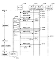
図1は、本発明の実施形態におけるネットワークカメラシステム100のブロック図である。ネットワークカメラシステム100は、ネットワークカメラ110、PC(Personal Computer)120およびネットワーク130を有する。ネットワークカメラ110は、撮像部111、信号処理部112、エンコード部113、一時メモリ114、送受信部115、画像送信監視部116、蓄積処理部117、蓄積容量監視部118、蓄積メモリ119を有する。PC120は、画像受信部121、蓄積画像取得要求部122、蓄積画像リスト取得部123を有する。
FIG. 1 is a block diagram of a
ここで、ネットワーク130は通信回線の一例である。また、ネットワークカメラ110はネットワークカメラの一例である。また、PC120は配信先の一例である受信装置である。また、撮像部111は撮像部の一例である。また、送受信部115は送信部の一例である。また、画像送信監視部116は送信監視部の一例である。また、蓄積メモリ119は蓄積部の一例である。また、蓄積容量監視部118は蓄積監視部の一例である。また、画像受信部121は受信部の一例である。
Here, the
ネットワークカメラ110およびPC120はネットワーク130に接続されている。ネットワークカメラ110は、ネットワーク130に接続することのできるカメラである。PC120は、ネットワークカメラ110によって撮影された画像データを閲覧するためのモニタリングPCや画像データを録画するための録画機器などである。
The
撮像部111は画像信号を入力する。信号処理部112は、入力された画像信号に対して、信号処理を行う。エンコード部113は、信号処理された画像信号に対して圧縮処理を行い、画像データとして一時メモリ114に一時的に保存する。また、ネットワークカメラシステム100の1週間のスケジュールを示した後述する図7のスケジュールテーブル114aも一時メモリ114に保存される。送受信部115は、一時メモリ114に保存された画像データおよび後述する図6の蓄積画像リスト117aをネットワーク130を介してPC120へ配信する。また、送受信部115は、PC120から送信される蓄積画像取得要求および蓄積画像リスト取得要求を受信し、一時メモリ114へ一時的に保存する。
The
画像送信監視部116は、送受信部115による画像データの配信の状態を監視し、配信が途切れた場合に蓄積処理部117へ通知する。蓄積処理部117は、画像送信監視部116による配信途切れの通知を受けた際、一時メモリ114に保存された画像データを蓄積メモリ119へ保存する。また、蓄積処理部117は、送受信部115によって蓄積画像取得要求を受信した際には蓄積メモリ119に保存された画像データを一時メモリ114へ引き渡し、一時メモリに一時的に保存する。また、蓄積処理部117は、蓄積画像リスト117aを作成し、一時メモリ114へ一時的に保存する。
The image
蓄積容量監視部118は、蓄積メモリ119への画像データの蓄積量を監視し、その結果を蓄積処理部117およびネットワーク130を介してPC120へ通知する。これにより、PC120は蓄積画像が存在するか否かを把握することができる。蓄積メモリ119は、SDメモリカードなどである。
The storage
画像受信部121は、送受信部115からネットワーク130を介して送信された画像データを受信する。蓄積画像取得要求部122は、蓄積画像リスト取得部123が取得した蓄積画像リスト117aに基づいて、PC120の処理負荷の軽い時間帯に、蓄積画像取得要求をネットワーク130を介してネットワークカメラ110へ送信し、送受信部115からネットワーク130を介して送信される蓄積画像を取得する。
The
蓄積画像リスト取得部123は、蓄積画像リスト取得要求をネットワーク130を介してネットワークカメラ110へ送信し、送受信部115からネットワーク130を介して送信される蓄積画像リスト117aを取得する。
The stored image
蓄積画像リスト117aは、蓄積メモリ119に蓄積された蓄積画像の詳細情報を有するリストである。リスト項目として、連続番号、画像生成日時、配信先IP、カメラ名称などを有する。蓄積画像リスト117aの一例を図6に示す。
The accumulated
図6において、連続番号には、1から順番に番号が記載される。画像生成日時には、該当画像が蓄積メモリ119に蓄積された日時が記載される。配信先IPには、画像蓄積時に画像送信監視部116が該当画像の配信を監視していた監視対象のPC120のIPアドレスが記載される。カメラ名称には、1台以上のネットワークカメラ110のうち、該当画像を蓄積したネットワークカメラ110のカメラ名が記載される。
In FIG. 6, the serial numbers are sequentially numbered from 1. In the image generation date and time, the date and time when the corresponding image is stored in the
スケジュールテーブル114aは、ネットワークカメラシステム100の1週間のスケジュールを示しており、項目として録画開始時間、録画終了時間、録画間隔および配信先IPを有する。スケジュールテーブル114aは一時メモリ114に保存されている。スケジュールテーブル114aはネットワークカメラ110側で作成されてもよいし、PC120側で作成後にネットワーク130を介してネットワークカメラ110へ送信してもよい。スケジュールテーブル114aの一例を図7に示す。
The schedule table 114a shows a one-week schedule of the
図7において、録画開始時間には、画像送信監視部116による監視中に送受信部115による画像の配信が途切れた場合に画像の蓄積を行う時間帯を示す録画期間の開始時間が記載される。録画終了時間には、録画期間の終了時間が記載される。録画間隔には、画像を蓄積メモリ119へ蓄積する時間間隔が記載される。配信先IPには、画像送信監視部116が画像の配信を監視する監視対象のPC120のIPアドレスが記載される。
In FIG. 7, the recording start time describes the start time of the recording period indicating the time zone in which the image is accumulated when the image transmission by the transmission /
次に、ネットワークカメラ110がPC120へ画像データを配信する際の監視手順について説明する。画像データの配信を監視する方法は、PC120が一定間隔毎に画像取得要求に基づいて一定量ずつ画像データの配信を行う場合の監視方法(クライアントプル)と、PC120の一度の画像取得要求に対してネットワークカメラ130が画像データを一度に配信する場合の監視方法(サーバプッシュ)とがある。
Next, a monitoring procedure when the
まず、クライアントプルの場合の画像配信監視手順について説明する。図2は本発明の実施形態におけるネットワークカメラシステム100のクライアントプルの場合の画像配信監視シーケンス図である。ここでは、ネットワークカメラシステム100は1台以上のネットワークカメラ110を有するサーバ、1台以上のPC120を有するn台(nは1以上の整数)のクライアントを有し、第2のクライアントからの画像取得要求のみを監視することにする。各サーバおよび各クライアントは同一の構成および機能を有している。サーバのうちの任意の1台をサーバ110Aとし、n台のクライアントを第1のクライアント120A、第2のクライアント120B、・・・、第nのクライアント120nとする。
First, an image distribution monitoring procedure in the case of client pull will be described. FIG. 2 is an image distribution monitoring sequence diagram in the case of the client pull of the
まず、画像取得要求が第1のクライアント120Aからサーバ110Aへ送信されてサーバAによって検出され(ステップS201)、サーバ110Aから第1のクライアント120Aへ画像が正常に配信されている(ステップS202)。また、画像取得要求が第2のクライアント120Bからサーバ110Aへ送信されてサーバ110Aによって検出され(ステップS203)、サーバ110Aから第2のクライアント120Bへ画像が正常に配信されている(ステップS204)。
First, an image acquisition request is transmitted from the
次に、画像取得要求が第2のクライアント120Bからサーバ110Aへ送信されたにもかかわらず、あらかじめ定めた設定時間内にサーバ110Aにおいて次の画像取得要求が検出されない場合(ステップS205)、第2のクライアント120Bからの画像取得要求は監視されているため、サーバ110Aは蓄積メモリ119へ画像の蓄積を開始する(ステップS206)。
Next, when the image acquisition request is transmitted from the
ここで、特定のクライアント(ここでは第2のクライアント120B)からの画像取得要求の送信において、サーバ110Aが画像取得要求を正常に受信すると、ACK(ACKnowledgement)がサーバ110Aからクライアント側へ送られるため、クライアントはサーバ110Aが正常に画像取得要求を受信したことを知ることができる。
Here, in the transmission of the image acquisition request from the specific client (here, the
ステップS205における画像取得要求の非検出からあらかじめ定めた設定時間tだけ経過した後、再び第2のクライアント120Bは画像取得要求をサーバ110Aへ送信する(ステップS207)。ステップS207における画像取得要求もサーバ110Aにおいて設定時間内に検出されない場合、引き続き蓄積メモリ119へ画像の蓄積を行う(ステップS208)。
After a predetermined set time t has elapsed since the non-detection of the image acquisition request in step S205, the
再び設定時間tだけ経過した後、画像取得要求が第2のクライアント120Bからサーバ110Aへ送信されてサーバ110Aによって要求が検出され(ステップS209)、サーバ110Aから第2のクライアント120Bへ画像が配信されている(ステップS210)。ステップS209において画像取得要求が正常に検出されているので、蓄積メモリ119への画像の蓄積を停止する(ステップS211)。
After the set time t has passed again, an image acquisition request is transmitted from the
また、画像取得要求が第1のクライアント120Aからサーバ110Aへ送信されたにもかかわらず、あらかじめ定めた設定時間内にサーバ110Aにおいて検出されない場合は、第1のクライアント120Aからの画像取得要求は監視されていないため、蓄積メモリ119への画像の蓄積を行わない(ステップS211)。
If the image acquisition request is not detected in the
また、画像取得要求が第nのクライアント120nからサーバ110Aへ送信されてサーバ110Aによって検出され(ステップS213)、サーバ110Aから第nのクライアント120nへ画像が正常に配信されている(ステップS214)。
以上がクライアントプルの場合の画像配信監視手順である。
An image acquisition request is transmitted from the
The above is the image distribution monitoring procedure in the case of client pull.
次に、サーバプッシュの場合の画像配信監視手順について説明する。図3は本発明の実施形態におけるネットワークカメラシステム100のサーバプッシュの場合の画像配信監視シーケンス図である。ここでネットワークカメラシステム100は、サーバ110A、第1のクライアント120A、第2のクライアント120B、・・・、第nのクライアント120nを有し、第2のクライアントへの画像配信のみを監視することにする。各クライアントは同一の構成および機能を有している。
Next, an image distribution monitoring procedure in the case of server push will be described. FIG. 3 is an image distribution monitoring sequence diagram in the case of server push in the
まず、画像配信開始要求が第1のクライアント120Aからサーバ110Aへ送信されると(ステップS301)、サーバ110Aから第1のクライアント120Aへ画像の配信が行われ、サーバ110Aが第1のクライアント120Aから画像配信停止要求を受信するまで、もしくは配信された画像が第1のクライアント120Aに正常に受信されなくなるまで画像の配信が続行される(ステップS302)。
First, when an image distribution start request is transmitted from the
ここで、特定のクライアント(ここでは第2のクライアント120B)からの各画像の配信において、クライアントが画像を正常に受信すると、ACKがクライアントからサーバ110A側へ送られるため、サーバ110Aはクライアントが正常に画像を受信したことを知ることができる。
Here, in the distribution of each image from a specific client (here, the
第1のクライアント120Aからサーバ110Aへの画像の配信途中であって、画像の正常な受信があらかじめ定められた設定時間以上の間検出されない場合は、第1のクライアント120Aは監視対象外のクライアントであるため、蓄積メモリ119への画像の蓄積は行われない(ステップS303)。
If an image is being delivered from the
次に、画像配信開始要求が第2のクライアント120Bからサーバ110Aへ送信され(ステップS304)、サーバ110Aから第2のクライアント120Bへ画像の配信が行われ、サーバ110Aが第2のクライアント120Bから画像配信停止要求を受信するまで、もしくは配信された画像が第2のクライアント120Bに正常に受信されなくなるまで画像の配信が継続される(ステップS305)。
Next, an image distribution start request is transmitted from the
第2のクライアント120Bからサーバ110Aへの画像の配信途中であって、画像の正常な受信(ACK等)があらかじめ定められた設定時間以上の間検出されない場合は(ステップS306)、第2のクライアント120Bは監視対象のクライアントであるため、蓄積メモリ119への画像の蓄積を開始する(ステップS307)。
When the image is being delivered from the
ステップS306を実施した後、あらかじめ定められた設定間隔毎にサーバ110Aから第2のクライアント120Bへ画像が再配信される(ステップS308)。この再配信によっても第2のクライアント120Bが画像の受信を検出を受信できない場合は、蓄積メモリ119への画像の蓄積を継続する(ステップS309)。図3においては第1回目の再配信以外は図示が省略されている。この再配信は、第2のクライアント120Bが正常に画像の受信を検出するまで、もしくは、あらかじめ定めた一定期間の間行われる。
After performing step S306, the image is redistributed from the
配信に失敗していた画像の再配信において、第2のクライアント120Bが正常に画像を受信したら(ステップS310)、蓄積メモリ119への画像の蓄積を停止する(ステップS311)。その後も配信する第2のクライアント120Bからの画像配信停止要求があるまで、もしくは配信された画像が第2のクライアント120Bに正常に受信されなくなるまで画像の配信が継続される(ステップS312)。
In the re-distribution of the image that has failed to be distributed, when the
画像配信停止要求が第2のクライアント120Bからサーバ110Aへ送信されてサーバ110Aが画像配信停止要求を検出すると、サーバ110Aは画像の配信を停止する(ステップS313)。また、画像配信開始要求が第nのクライアント120nからサーバ110Aへ送信されると(ステップS314)、サーバ110Aから第nのクライアント120nへ画像の配信が行われ、サーバ110Aが第nのクライアント120nから画像配信停止要求を受信するまで、もしくは配信された画像が第nのクライアント120nに正常に受信されなくなるまで画像の配信が続行される(ステップS315)。
以上がサーバプッシュの場合の画像配信監視手順である。
When the image delivery stop request is transmitted from the
The above is the image distribution monitoring procedure in the case of server push.
次に、画像を蓄積メモリ119へ蓄積した後の蓄積画像存在通知および蓄積画像の取得について説明する。図4は本発明の実施形態におけるネットワークカメラシステム100の蓄積画像存在通知および蓄積画像取得シーケンス図である。ここでネットワークカメラシステム100は、サーバ110A、第1のクライアント120A、第2のクライアント120B、・・・、第nのクライアント120nを有し、第2のクライアントが蓄積画像取得を行う場合を想定している。
Next, the accumulated image presence notification and the accumulated image acquisition after the image is accumulated in the
まず、サーバ110Aに蓄積された蓄積画像の詳細を示した蓄積画像リスト117aが各クライアント120A、120B、・・・、120nへブロードキャスト通知される(ステップS401)。このブロードキャスト通知は、あらかじめ定められた一定時間毎に行われる。
First, a stored
第2のクライアント120Bは蓄積画像リスト117aの受信によって蓄積画像の存在を認識すると、第2のクライアント120B自身の動作負荷が軽い時間帯に蓄積画像取得要求をサーバ110Aへ送信する(ステップS402)。サーバ110Aは蓄積画像取得要求を受信すると、蓄積メモリ119から蓄積画像を取り出して第2のクライアント120Bへが蓄積画像を配信する(ステップS403)。一度に配信できる蓄積画像の量はあらかじめ定められている。第2のクライアント120Bへの送信が完了した蓄積画像は、蓄積メモリ119から削除される(ステップS404)。
When the
ステップS402の蓄積画像取得要求に対する蓄積画像の配信が第2のクライアント120Bによって検出されない場合(ステップS405)、第2のクライアント120Bへの蓄積画像の送信が完了していないので、送信予定であった蓄積画像は蓄積メモリ119から削除されない(ステップS406)。
If the distribution of the stored image in response to the stored image acquisition request in step S402 is not detected by the
また、ステップS401では一定時間間隔で蓄積画像リスト117aのブロードキャスト通知を示したが、例えば第2のクライアント120Bが蓄積画像リスト取得要求をサーバ110Aへ送信し(ステップS407)、それに対して蓄積画像リスト117aの通知を行うようにしてもよい(ステップS408)。
In step S401, broadcast notification of the stored
ここで、サーバ110Aの蓄積処理部117が蓄積画像リスト117aを作成するタイミングとしては、蓄積メモリ119への蓄積画像が発生する毎に蓄積画像リスト117aへ追記する、各クライアントから蓄積画像リスト取得要求を受信したときに蓄積メモリ119に蓄積されている画像の情報を一覧で作成する、あらかじめ定められた一定時間毎に蓄積画像リスト117aを更新するなど、様々なタイミングが考えられる。
以上が蓄積画像存在通知および蓄積画像取得の手順である。
Here, as the timing at which the storage processing unit 117 of the
The above is the stored image presence notification and stored image acquisition procedure.
次に、ネットワークカメラシステム100の録画スケジュールについて説明する。図5は本発明の実施形態におけるネットワークカメラシステム100の録画スケジュールに基づいた録画シーケンス図である。ここでは、金曜日から土曜日にかけての図7のような録画スケジュールに関して、詳細に説明する。ここでネットワークカメラシステム100は、サーバ110A、第1のクライアント120A、第2のクライアント120B、・・・、第nのクライアント120nを有する。
Next, a recording schedule of the
図7から、金曜日においては録画開始時間は8:30、録画終了時間は22:00、録画間隔は6秒、配信先IPは第1のクライアント120A、第2のクライアント120Bとなっているので、金曜日の8:30になると、ネットワークカメラシステム100は第1のクライアント120Aおよび第2のクライアント120Bへの画像配信の監視を開始する。
From FIG. 7, on Friday, the recording start time is 8:30, the recording end time is 22:00, the recording interval is 6 seconds, and the distribution destination IP is the
画像配信を監視されている期間は、画像取得要求が第2のクライアント120Bからサーバ110Aへ送信される(ステップS501)と、サーバ110Aは第2のクライアント120Bへ画像を配信する(ステップS502)。画像取得要求はあらかじめ定められた一定時間間隔で送信される。画像取得要求が第2のクライアント120Bからサーバ110Aへ送信された後(ステップS501)、設定時間以上経っても第2のクライアント120Bが画像の配信を検出できない場合は(ステップS503)、蓄積メモリ119への画像の蓄積を開始する(ステップS504)。
During the period when image distribution is monitored, when an image acquisition request is transmitted from the
また、画像取得要求が第1のクライアント120Aからサーバ110Aへ送信され(ステップS505)、サーバ110Aが第1のクライアント120Aへ画像の配信を行うことができたとしても(ステップS506)、第2のクライアント120Bへの画像の配信が途切れてしまっている場合は蓄積メモリ119への画像の蓄積を継続する(ステップS507)。この蓄積メモリ119への画像の蓄積は、録画間隔毎に行うので、ここでは6秒毎に画像の蓄積を行う。
The image acquisition request is sent from the
画像取得要求が第2のクライアント120Bからサーバ110Aへ送信され(ステップS508)、第2のクライアント120Bが蓄積画像の配信を検出し(ステップS509)、かつ、画像取得要求が第1のクライアント120Aからサーバ110Aへ送信され(ステップS510)、第1のクライアント120Aが蓄積画像の配信を検出した場合(ステップS511)、つまり、監視対象の第1のクライアント120Aおよび第2のクライアント120Bの両方への画像配信が実施可能であれば、蓄積メモリ119への画像の蓄積を停止する(ステップS512)。
An image acquisition request is transmitted from the
また、画像配信を監視されている期間であって、監視対象外である第nのクライアント120nが画像取得要求をサーバ110Aへ送信されても(ステップS513)、サーバ110Aから第nのクライアント120nへの画像の配信は行われない(ステップS514)。
Further, even if the
また、画像配信の監視対象である第2のクライアント120Bから画像取得要求がサーバ110Aへ送信されても(ステップ515)、例えば金曜日の22:00より遅く土曜日の9:00より早い時間帯のような録画非対象期間内の画像取得要求に対しては、サーバ110Aから第2のクライアント120Bへの画像の配信は行われない(ステップS516)。
以上が録画スケジュールに基づいた録画手順である。
このように、録画期間を設定することで、サーバ側であるネットワークカメラの蓄積メモリの容量を効率よく活用することができる。
Further, even when an image acquisition request is transmitted from the
The above is the recording procedure based on the recording schedule.
Thus, by setting the recording period, the capacity of the storage memory of the network camera on the server side can be efficiently utilized.
このような本発明の実施形態におけるネットワークカメラシステム100によれば、ネットワーク130に接続された、ネットワークカメラ110およびネットワークカメラ110によって画像を配信される複数のPC120を有するネットワークカメラシステム100であって、ネットワークカメラ110は、画像を撮像する撮像部111と、PC120へ撮像部111によって撮像された撮像画像を配信する送受信部115と、撮像画像が複数のPC120のうちの予め指定されたPC120へ送受信部115によって配信されたか否かを監視する画像送信監視部116と、画像送信監視部116によって監視された送受信部115による指定されたPC120への配信が途切れた場合に、撮像画像を蓄積する蓄積メモリ119とを有し、PC120は、送受信部115によって指定されたPC120へ配信された撮像画像を受信する画像受信部121を有する構成とすることで、指定されたPC120へ確実に画像を配信することができる。
According to the
本発明は、指定された配信先へ確実に画像を配信することができるネットワークカメラ、ネットワークカメラシステム等に有用である。 The present invention is useful for a network camera, a network camera system, and the like that can reliably deliver an image to a designated delivery destination.
100 ネットワークカメラシステム
110 ネットワークカメラ
111 撮像部
112 信号処理部
113 エンコード部
114 一時メモリ
115 送受信部
116 画像送信監視部
117 蓄積処理部
118 蓄積容量監視部
119 蓄積メモリ
120 PC(受信装置)
121 画像受信部
122 蓄積画像取得要求部
123 蓄積画像リスト取得部
130 ネットワーク
DESCRIPTION OF
121
Claims (8)
画像を撮像する撮像部と、
前記撮像部によって撮像された撮像画像の配信を要求する前記受信装置へ前記撮像画像を配信する送信部と、
前記撮像画像が予め指定された受信装置へ前記送信部によって配信されたか否かを監視する送信監視部と、
前記送信監視部によって監視され、前記予め指定された受信装置への配信が途切れた場合にのみ、前記撮像画像を蓄積し、前記予め指定された受信装置以外への配信が途切れた場合には前記撮像画像を蓄積しない蓄積部と、を有するネットワークカメラ。 A network camera capable of distributing images to a plurality of receiving devices via a communication line,
An imaging unit that captures an image;
A transmission unit that distributes the captured image to the receiving device that requests distribution of the captured image captured by the imaging unit;
A transmission monitoring unit the captured image monitors whether delivered by the transmitting unit to a receiving device specified Me pre,
Is monitored by the transmission monitoring unit, only when the distribution of the pre-designated receiving apparatus is interrupted, the captured image and storing, the if the distribution of the non-pre-designated receiving apparatus is interrupted And a storage unit that does not store captured images.
前記蓄積部は、
前記予め指定された受信装置への配信が復帰した場合に前記撮像画像の蓄積を停止するネットワークカメラ。 The network camera according to claim 1,
The storage unit
A network camera that stops accumulation of the captured image when delivery to the receiving device designated in advance is restored.
前記蓄積部は、設定時間内に前記予め指定された受信装置から撮像画像の配信を要求されない場合または設定時間内に前記予め指定された受信装置から撮像画像の正常な受信を検出されない場合に前記撮像画像の蓄積を開始するネットワークカメラ。 The network camera according to claim 1 or 2,
When the storage unit does not request delivery of a captured image from the predesignated receiving device within a set time, or when normal reception of the captured image is not detected from the predesignated receiving device within a set time, A network camera that starts storing captured images.
前記蓄積部によって前記撮像画像を蓄積する時間間隔を含む蓄積間隔情報を有し、
前記蓄積部は、
前記予め指定された受信装置への配信が途切れた場合に、前記時間間隔で前記撮像画像の蓄積をするネットワークカメラ。 The network camera according to claim 1 or 2,
Having storage interval information including a time interval for storing the captured image by the storage unit;
The storage unit
A network camera that accumulates the captured images at the time intervals when distribution to the reception device designated in advance is interrupted .
前記蓄積部によって前記撮像画像が蓄積されていることを前記受信装置へ通知する蓄積監視部を有するネットワークカメラ。 The network camera according to any one of claims 1 to 4,
A network camera having an accumulation monitoring unit that notifies the receiving device that the captured image is accumulated by the accumulation unit.
前記送信監視部によって前記予め指定された受信装置への前記撮像画像の配信を監視する監視時間帯を示す録画期間を含む録画時間情報を有し、
前記蓄積部は、
前記録画期間に前記予め指定された受信装置への配信が途切れた場合、前記撮像画像の蓄積をするネットワークカメラ。 The network camera according to any one of claims 1 to 5,
Recording time information including a recording period indicating a monitoring time zone for monitoring the delivery of the captured image to the reception device designated in advance by the transmission monitoring unit;
The storage unit
A network camera that accumulates the captured image when distribution to the reception device designated in advance is interrupted during the recording period .
前記ネットワークカメラは、
画像を撮像する撮像部と、
前記受信装置へ前記撮像部によって撮像された撮像画像を配信する送信部と、
前記撮像画像が予め指定された受信装置へ前記送信部によって配信されたか否かを監視する送信監視部と、
前記送信監視部によって監視され、前記予め指定された受信装置への配信が途切れた場合にのみ、前記撮像画像を蓄積し、前記予め指定された受信装置以外への配信が途切れた場合には前記撮像画像を蓄積しない蓄積部とを有し、
前記受信装置は、
前記送信部によって配信された前記撮像画像を受信する受信部を有するネットワークカメラシステム。 A network camera system having a network camera connected to a communication line and a plurality of receiving devices to which images are distributed by the network camera,
The network camera
An imaging unit that captures an image;
A transmission unit that distributes the captured image captured by the imaging unit to the receiving device;
A transmission monitoring unit the captured image monitors whether delivered by the transmitting unit to a receiving device specified Me pre,
Is monitored by the transmission monitoring unit, only when the distribution of the pre-designated receiving apparatus is interrupted, the captured image and storing, the if the distribution of the non-pre-designated receiving apparatus is interrupted A storage unit that does not store captured images;
The receiving device is:
Network camera system having a receiver for receiving the captured image delivery by the transmission unit.
前記ネットワークカメラにより、
画像を撮影する撮像ステップと、
前記受信装置へ前記撮像ステップにおいて撮像された撮像画像を配信する送信ステップと、
前記撮像画像が予め指定された受信装置へ前記送信ステップにおける配信がされたか否かを監視する送信監視ステップと、
前記送信監視ステップにおいて監視された、前記予め指定された受信装置への配信が途切れた場合にのみ、前記撮像画像を蓄積し、前記予め指定された受信装置以外への配信が途切れた場合には前記撮像画像を蓄積しない蓄積ステップと、
前記受信装置により、
前記送信ステップにおいて配信された撮像画像を受信するステップと、
を有する監視方法。 A monitoring method by a network system having a network camera connected to a communication line and a plurality of receiving devices to which images are distributed by the network camera,
With the network camera
An imaging step for taking an image;
A transmission step of distributing the captured image captured in the imaging step to the receiving device;
And transmitting monitoring step in which the captured image is to monitor whether or not the delivery of the transmitting step to the reception device specified Me pre,
Was monitored at the transmitting monitoring step, before Ki予 Me delivered to the specified receiver when interrupted only accumulates the captured image, delivery interruption to non pre Ki予 Me designated receiving device a storage step without storing the captured image in the case were,
By the receiving device ,
Receiving the distributed captured image at the transmitting step,
Monitoring method.
Priority Applications (5)
| Application Number | Priority Date | Filing Date | Title |
|---|---|---|---|
| JP2005334548A JP4712537B2 (en) | 2005-11-18 | 2005-11-18 | Network camera, network camera system, and monitoring method |
| PCT/JP2006/322882 WO2007058269A1 (en) | 2005-11-18 | 2006-11-16 | Network camera, network camera system, monitor method |
| CN2006800431769A CN101313571B (en) | 2005-11-18 | 2006-11-16 | Network camera, network camera system, monitor method |
| EP06832762A EP1956843A1 (en) | 2005-11-18 | 2006-11-16 | Network camera, network camera system, monitor method |
| US12/094,095 US9113065B2 (en) | 2005-11-18 | 2006-11-16 | Network camera, network camera system and monitoring method |
Applications Claiming Priority (1)
| Application Number | Priority Date | Filing Date | Title |
|---|---|---|---|
| JP2005334548A JP4712537B2 (en) | 2005-11-18 | 2005-11-18 | Network camera, network camera system, and monitoring method |
Publications (3)
| Publication Number | Publication Date |
|---|---|
| JP2007142861A JP2007142861A (en) | 2007-06-07 |
| JP2007142861A5 JP2007142861A5 (en) | 2008-08-14 |
| JP4712537B2 true JP4712537B2 (en) | 2011-06-29 |
Family
ID=38048653
Family Applications (1)
| Application Number | Title | Priority Date | Filing Date |
|---|---|---|---|
| JP2005334548A Expired - Fee Related JP4712537B2 (en) | 2005-11-18 | 2005-11-18 | Network camera, network camera system, and monitoring method |
Country Status (5)
| Country | Link |
|---|---|
| US (1) | US9113065B2 (en) |
| EP (1) | EP1956843A1 (en) |
| JP (1) | JP4712537B2 (en) |
| CN (1) | CN101313571B (en) |
| WO (1) | WO2007058269A1 (en) |
Families Citing this family (6)
| Publication number | Priority date | Publication date | Assignee | Title |
|---|---|---|---|---|
| CN101742197B (en) * | 2008-11-18 | 2012-10-03 | 华为技术有限公司 | Front-end equipment, video file backup method and control method, device and system thereof |
| JP5316550B2 (en) * | 2011-01-05 | 2013-10-16 | 株式会社デンソー | Rear view support system |
| EP2538672B1 (en) * | 2011-06-21 | 2020-08-12 | Axis AB | Method for configuring networked cameras |
| WO2014207882A1 (en) * | 2013-06-28 | 2014-12-31 | 株式会社 日立産業制御ソリューションズ | Network camera, network camera control terminal, and video recording/delivering system |
| JP6249754B2 (en) * | 2013-12-13 | 2017-12-20 | オリンパス株式会社 | IMAGING DEVICE, IMAGING SYSTEM, COMMUNICATION DEVICE, IMAGING METHOD, AND IMAGING PROGRAM |
| EP3869813B1 (en) * | 2020-02-24 | 2022-03-30 | Axis AB | Streaming of a live video stream |
Citations (5)
| Publication number | Priority date | Publication date | Assignee | Title |
|---|---|---|---|---|
| JP2003018525A (en) * | 2001-07-04 | 2003-01-17 | Fujitsu Ltd | Network storage type video camera system |
| JP2004147262A (en) * | 2002-10-28 | 2004-05-20 | Matsushita Electric Ind Co Ltd | Network camera instrument and camera video distribution method |
| JP2005026866A (en) * | 2003-06-30 | 2005-01-27 | Sony Corp | Network camera |
| JP2005295255A (en) * | 2004-03-31 | 2005-10-20 | Toshiba Corp | Imaging apparatus and method for transmitting photographed image |
| JP2007049681A (en) * | 2005-07-11 | 2007-02-22 | Canon Inc | Network camera device, and transmitting method of video frame of the same |
Family Cites Families (12)
| Publication number | Priority date | Publication date | Assignee | Title |
|---|---|---|---|---|
| DE69712481T2 (en) * | 1996-06-28 | 2002-12-19 | T Eric Hopkins | IMAGE DETECTION SYSTEM AND METHOD |
| CN2588705Y (en) * | 2002-07-15 | 2003-11-26 | 李鹏 | High-safety network camera |
| JP4276452B2 (en) * | 2003-02-18 | 2009-06-10 | パナソニック株式会社 | Network camera |
| JP2004320642A (en) * | 2003-04-18 | 2004-11-11 | Sumitomo Electric Ind Ltd | Moving body notifying method, moving body detecting method, image-taking device, and moving body detecting system |
| US20060268122A1 (en) * | 2003-09-01 | 2006-11-30 | Mariko Iwasaki | Camera having transmission function, mobile telephone device, and image data acquiring/transmitting program |
| US20050052548A1 (en) * | 2003-09-09 | 2005-03-10 | Delaney Beth M. P. | Digital camera and method providing automatic image file backup during upload |
| CN2636533Y (en) * | 2003-09-11 | 2004-08-25 | 上海复旦聚升信息科技有限公司 | Network camera |
| JP2005339361A (en) * | 2004-05-28 | 2005-12-08 | Fuji Photo Film Co Ltd | Image display device, method and program |
| JP4535317B2 (en) | 2004-05-31 | 2010-09-01 | 株式会社吉野工業所 | Compact container |
| US7698487B2 (en) * | 2004-06-30 | 2010-04-13 | Intel Corporation | Share resources and increase reliability in a server environment |
| HK1066447A2 (en) * | 2004-09-14 | 2005-02-04 | Multivision Intelligent Surveillance Hong Kong Ltd | Backup system for digital surveillance system |
| US7877777B2 (en) | 2006-06-23 | 2011-01-25 | Canon Kabushiki Kaisha | Network camera apparatus and distributing method of video frames |
-
2005
- 2005-11-18 JP JP2005334548A patent/JP4712537B2/en not_active Expired - Fee Related
-
2006
- 2006-11-16 WO PCT/JP2006/322882 patent/WO2007058269A1/en active Search and Examination
- 2006-11-16 EP EP06832762A patent/EP1956843A1/en not_active Withdrawn
- 2006-11-16 CN CN2006800431769A patent/CN101313571B/en not_active Expired - Fee Related
- 2006-11-16 US US12/094,095 patent/US9113065B2/en active Active
Patent Citations (5)
| Publication number | Priority date | Publication date | Assignee | Title |
|---|---|---|---|---|
| JP2003018525A (en) * | 2001-07-04 | 2003-01-17 | Fujitsu Ltd | Network storage type video camera system |
| JP2004147262A (en) * | 2002-10-28 | 2004-05-20 | Matsushita Electric Ind Co Ltd | Network camera instrument and camera video distribution method |
| JP2005026866A (en) * | 2003-06-30 | 2005-01-27 | Sony Corp | Network camera |
| JP2005295255A (en) * | 2004-03-31 | 2005-10-20 | Toshiba Corp | Imaging apparatus and method for transmitting photographed image |
| JP2007049681A (en) * | 2005-07-11 | 2007-02-22 | Canon Inc | Network camera device, and transmitting method of video frame of the same |
Also Published As
| Publication number | Publication date |
|---|---|
| US20090174770A1 (en) | 2009-07-09 |
| EP1956843A1 (en) | 2008-08-13 |
| JP2007142861A (en) | 2007-06-07 |
| US9113065B2 (en) | 2015-08-18 |
| CN101313571B (en) | 2011-04-27 |
| CN101313571A (en) | 2008-11-26 |
| WO2007058269A1 (en) | 2007-05-24 |
Similar Documents
| Publication | Publication Date | Title |
|---|---|---|
| JP4712537B2 (en) | Network camera, network camera system, and monitoring method | |
| TWI568269B (en) | Method for configuring networked cameras | |
| CN1976447B (en) | Network camera system and network camera control method | |
| EP2112806B1 (en) | Information collecting system | |
| EP3119075A1 (en) | Information processing apparatus, storage medium and control method | |
| JP5517417B2 (en) | Monitoring device, control method therefor, and program | |
| WO2007069658A1 (en) | Data acquisition apparatus, data recording system, and data recording method | |
| JP2007142861A5 (en) | ||
| KR101716183B1 (en) | Network camera and surveillance system includint the same | |
| KR20150074867A (en) | System for analyzing multi-channel image based on extraction of image transition and method thereof | |
| US20100013634A1 (en) | Distributed systems monitoring system | |
| JP2006345208A (en) | Video monitor system, monitor video management device and monitor video providing device | |
| JP4533708B2 (en) | Surveillance camera system, control device for surveillance camera system, and control method | |
| KR101868939B1 (en) | Image duplexing repeater system using ip camera | |
| CN106162051B (en) | Image display system | |
| US20120105652A1 (en) | Network camera and method of operating storage device thereof | |
| JP2001326926A (en) | Data distribution mode and data distribution method | |
| KR101811152B1 (en) | Video storage/distribution device, system, method and recording medium | |
| JP6740002B2 (en) | Control device, control method and program | |
| JP2006203342A (en) | System for monitoring video image | |
| JP6476995B2 (en) | Relay device, content distribution system, relay method and program | |
| JP2007013733A (en) | Device and method for creating file | |
| JP4683609B2 (en) | Image management apparatus, image acquisition apparatus, image management system, image management apparatus control method, image acquisition apparatus control method, and program | |
| JP2005092645A (en) | Printing result information management system | |
| JP2008193443A (en) | Video image collecting method, video image collection system, program for video image collection, and computer readable recording medium with the program recorded |
Legal Events
| Date | Code | Title | Description |
|---|---|---|---|
| RD02 | Notification of acceptance of power of attorney |
Free format text: JAPANESE INTERMEDIATE CODE: A7422 Effective date: 20071113 |
|
| RD04 | Notification of resignation of power of attorney |
Free format text: JAPANESE INTERMEDIATE CODE: A7424 Effective date: 20071120 |
|
| A521 | Request for written amendment filed |
Free format text: JAPANESE INTERMEDIATE CODE: A523 Effective date: 20080702 |
|
| A621 | Written request for application examination |
Free format text: JAPANESE INTERMEDIATE CODE: A621 Effective date: 20080702 |
|
| A131 | Notification of reasons for refusal |
Free format text: JAPANESE INTERMEDIATE CODE: A131 Effective date: 20100831 |
|
| A521 | Request for written amendment filed |
Free format text: JAPANESE INTERMEDIATE CODE: A523 Effective date: 20101027 |
|
| A01 | Written decision to grant a patent or to grant a registration (utility model) |
Free format text: JAPANESE INTERMEDIATE CODE: A01 Effective date: 20110222 |
|
| A61 | First payment of annual fees (during grant procedure) |
Free format text: JAPANESE INTERMEDIATE CODE: A61 Effective date: 20110323 |
|
| LAPS | Cancellation because of no payment of annual fees |