JP4708869B2 - Information processing apparatus and control method thereof - Google Patents
Information processing apparatus and control method thereof Download PDFInfo
- Publication number
- JP4708869B2 JP4708869B2 JP2005168409A JP2005168409A JP4708869B2 JP 4708869 B2 JP4708869 B2 JP 4708869B2 JP 2005168409 A JP2005168409 A JP 2005168409A JP 2005168409 A JP2005168409 A JP 2005168409A JP 4708869 B2 JP4708869 B2 JP 4708869B2
- Authority
- JP
- Japan
- Prior art keywords
- information
- processing
- saving mode
- distributed processing
- power saving
- Prior art date
- Legal status (The legal status is an assumption and is not a legal conclusion. Google has not performed a legal analysis and makes no representation as to the accuracy of the status listed.)
- Expired - Fee Related
Links
Images


Classifications
-
- G—PHYSICS
- G06—COMPUTING; CALCULATING OR COUNTING
- G06F—ELECTRIC DIGITAL DATA PROCESSING
- G06F3/00—Input arrangements for transferring data to be processed into a form capable of being handled by the computer; Output arrangements for transferring data from processing unit to output unit, e.g. interface arrangements
- G06F3/12—Digital output to print unit, e.g. line printer, chain printer
- G06F3/1201—Dedicated interfaces to print systems
- G06F3/1223—Dedicated interfaces to print systems specifically adapted to use a particular technique
- G06F3/1237—Print job management
- G06F3/126—Job scheduling, e.g. queuing, determine appropriate device
-
- G—PHYSICS
- G03—PHOTOGRAPHY; CINEMATOGRAPHY; ANALOGOUS TECHNIQUES USING WAVES OTHER THAN OPTICAL WAVES; ELECTROGRAPHY; HOLOGRAPHY
- G03G—ELECTROGRAPHY; ELECTROPHOTOGRAPHY; MAGNETOGRAPHY
- G03G15/00—Apparatus for electrographic processes using a charge pattern
- G03G15/50—Machine control of apparatus for electrographic processes using a charge pattern, e.g. regulating differents parts of the machine, multimode copiers, microprocessor control
- G03G15/5075—Remote control machines, e.g. by a host
-
- G—PHYSICS
- G06—COMPUTING; CALCULATING OR COUNTING
- G06F—ELECTRIC DIGITAL DATA PROCESSING
- G06F3/00—Input arrangements for transferring data to be processed into a form capable of being handled by the computer; Output arrangements for transferring data from processing unit to output unit, e.g. interface arrangements
- G06F3/12—Digital output to print unit, e.g. line printer, chain printer
- G06F3/1201—Dedicated interfaces to print systems
- G06F3/1202—Dedicated interfaces to print systems specifically adapted to achieve a particular effect
- G06F3/1218—Reducing or saving of used resources, e.g. avoiding waste of consumables or improving usage of hardware resources
- G06F3/1221—Reducing or saving of used resources, e.g. avoiding waste of consumables or improving usage of hardware resources with regard to power consumption
-
- G—PHYSICS
- G06—COMPUTING; CALCULATING OR COUNTING
- G06F—ELECTRIC DIGITAL DATA PROCESSING
- G06F3/00—Input arrangements for transferring data to be processed into a form capable of being handled by the computer; Output arrangements for transferring data from processing unit to output unit, e.g. interface arrangements
- G06F3/12—Digital output to print unit, e.g. line printer, chain printer
- G06F3/1201—Dedicated interfaces to print systems
- G06F3/1223—Dedicated interfaces to print systems specifically adapted to use a particular technique
- G06F3/1229—Printer resources management or printer maintenance, e.g. device status, power levels
-
- G—PHYSICS
- G06—COMPUTING; CALCULATING OR COUNTING
- G06F—ELECTRIC DIGITAL DATA PROCESSING
- G06F3/00—Input arrangements for transferring data to be processed into a form capable of being handled by the computer; Output arrangements for transferring data from processing unit to output unit, e.g. interface arrangements
- G06F3/12—Digital output to print unit, e.g. line printer, chain printer
- G06F3/1201—Dedicated interfaces to print systems
- G06F3/1278—Dedicated interfaces to print systems specifically adapted to adopt a particular infrastructure
- G06F3/1285—Remote printer device, e.g. being remote from client or server
-
- G—PHYSICS
- G03—PHOTOGRAPHY; CINEMATOGRAPHY; ANALOGOUS TECHNIQUES USING WAVES OTHER THAN OPTICAL WAVES; ELECTROGRAPHY; HOLOGRAPHY
- G03G—ELECTROGRAPHY; ELECTROPHOTOGRAPHY; MAGNETOGRAPHY
- G03G2215/00—Apparatus for electrophotographic processes
- G03G2215/00025—Machine control, e.g. regulating different parts of the machine
- G03G2215/00109—Remote control of apparatus, e.g. by a host
-
- G—PHYSICS
- G03—PHOTOGRAPHY; CINEMATOGRAPHY; ANALOGOUS TECHNIQUES USING WAVES OTHER THAN OPTICAL WAVES; ELECTROGRAPHY; HOLOGRAPHY
- G03G—ELECTROGRAPHY; ELECTROPHOTOGRAPHY; MAGNETOGRAPHY
- G03G2215/00—Apparatus for electrophotographic processes
- G03G2215/01—Apparatus for electrophotographic processes for producing multicoloured copies
- G03G2215/0167—Apparatus for electrophotographic processes for producing multicoloured copies single electrographic recording member
- G03G2215/0174—Apparatus for electrophotographic processes for producing multicoloured copies single electrographic recording member plural rotations of recording member to produce multicoloured copy
- G03G2215/0177—Rotating set of developing units
-
- Y—GENERAL TAGGING OF NEW TECHNOLOGICAL DEVELOPMENTS; GENERAL TAGGING OF CROSS-SECTIONAL TECHNOLOGIES SPANNING OVER SEVERAL SECTIONS OF THE IPC; TECHNICAL SUBJECTS COVERED BY FORMER USPC CROSS-REFERENCE ART COLLECTIONS [XRACs] AND DIGESTS
- Y02—TECHNOLOGIES OR APPLICATIONS FOR MITIGATION OR ADAPTATION AGAINST CLIMATE CHANGE
- Y02D—CLIMATE CHANGE MITIGATION TECHNOLOGIES IN INFORMATION AND COMMUNICATION TECHNOLOGIES [ICT], I.E. INFORMATION AND COMMUNICATION TECHNOLOGIES AIMING AT THE REDUCTION OF THEIR OWN ENERGY USE
- Y02D10/00—Energy efficient computing, e.g. low power processors, power management or thermal management
Landscapes
- Engineering & Computer Science (AREA)
- Theoretical Computer Science (AREA)
- Physics & Mathematics (AREA)
- General Physics & Mathematics (AREA)
- Human Computer Interaction (AREA)
- General Engineering & Computer Science (AREA)
- Microelectronics & Electronic Packaging (AREA)
- Accessory Devices And Overall Control Thereof (AREA)
- Power Sources (AREA)
Description
本発明は情報処理装置およびその制御方法に関し、例えば、コンピュータネットワークに接続されたプリンタや複合機能印刷装置などの情報処理装置にグリッドコンピューティングの負荷分散システムを適用する処理や制御に関する。 The present invention relates to an information processing apparatus and a control method therefor, and relates to, for example, processing and control in which a grid computing load distribution system is applied to an information processing apparatus such as a printer or a multi-function printing apparatus connected to a computer network.
大量の処理を分散して複数の機器で処理し、高速処理を可能とする機構は複数の提案されている(例えばグリッドコンピューティングなど、非特許文献1)。 A plurality of mechanisms that enable high-speed processing by distributing a large amount of processing by a plurality of devices have been proposed (for example, non-patent document 1 such as grid computing).
ネットワーク接続された複数の機器をフル活用し、クライアントからジョブを受け取って膨大な時間のかかる処理を行う場合に、グリッドコンピューティングのフレームワークを使用して、複数の機器の処理能力を有効活用し、より高速な分散処理を実現することが期待される。 Use the grid computing framework to effectively utilize the processing power of multiple devices when you make full use of multiple devices connected to the network and receive jobs from clients to perform a long process. It is expected to realize faster distributed processing.
一方、近年、省エネルギの意識が高まり、未使用状態の機器を自動的に省電力モードに移行させ、待機させる手段が一般的になった。このような機器をネットワーク接続して、他の機器から依頼されるジョブを処理する場合、省電力モードに移行する条件に該当せず、多くの機器は、省電力モードで待機する機会を失う。その結果、省エネルギの効果が損われる場合がある。 On the other hand, in recent years, awareness of energy saving has increased, and a means for automatically transitioning an unused device to a power saving mode and waiting is becoming common. When such a device is connected to the network and a job requested from another device is processed, the condition for shifting to the power saving mode is not satisfied, and many devices lose the opportunity to stand by in the power saving mode. As a result, the energy saving effect may be impaired.
本発明は、分散処理の対象機器の迅速な選択と、分散処理における消費電力の抑制を目的とする。 An object of the present invention is to quickly select a target device for distributed processing and to reduce power consumption in the distributed processing.
本発明にかかる情報処理装置は、コンピュータネットワークに接続された、省電力モードを有する複数の機器による分散処理を管理する情報処理装置であって、前記複数の機器の機器情報および動作状況を取得する取得手段と、前記機器から取得した機器情報が前記機器の通常動作における消費電力が閾値以下を示す場合は、当該機器の省電力モードに関する動作状況を判定することなく、当該機器を前記分散処理の対象機器として選択し、前記機器情報が前記機器の通常動作における消費電力が前記閾値を超えることを示し、当該機器が省電力モードにある場合は、当該機器を分散処理の対象機器として選択しない選択手段とを有することを特徴とする。 An information processing apparatus according to the present invention is an information processing apparatus for managing distributed processing by a plurality of devices having a power saving mode connected to a computer network, and acquires device information and operation status of the plurality of devices. When the acquisition unit and the device information acquired from the device indicate that the power consumption in the normal operation of the device is equal to or less than the threshold , the device is not subjected to the distributed processing without determining the operation status related to the power saving mode of the device. selected as a target device selection indicates that the device information is power consumption in the normal operation of the device exceeds the threshold value, if the device is in the power saving mode, which does not select the device as the target device of the distributed processing Means.
本発明にかかる制御方法は、コンピュータネットワークに接続された、省電力モードを有する複数の機器による分散処理を管理する情報処理装置の制御方法であって、前記複数の機器の機器情報および動作状況を取得し、前記機器から取得した機器情報が前記機器の通常動作における消費電力が閾値以下を示す場合は、当該機器の省電力モードに関する動作状況を判定することなく、当該機器を前記分散処理の対象機器として選択し、前記機器情報が前記機器の通常動作における消費電力が前記閾値を超えることを示し、当該機器が省電力モードにある場合は、当該機器を分散処理の対象機器として選択しないことを特徴とする。 A control method according to the present invention is a control method of an information processing apparatus that manages distributed processing by a plurality of devices having a power saving mode connected to a computer network, and includes device information and operation status of the plurality of devices. When the device information acquired and the device information acquired from the device indicates that the power consumption in the normal operation of the device is less than or equal to the threshold , the device is subject to the distributed processing without determining the operation status related to the power saving mode of the device. select the device indicates that the device information is power consumption in the normal operation of the device exceeds the threshold value, if the device is in the power saving mode, not to select the device as the target device of the distributed processing Features.
本発明によれば、分散処理の対象機器の迅速な選択と、分散処理における消費電力の抑制が可能になる。 According to the present invention, a rapid selection of the target device of the distributed processing, can be ing suppress power consumption in the distributed processing.
以下、図面を参照して、本発明に好適な一実施例を詳細に説明する。 Hereinafter, an embodiment suitable for the present invention will be described in detail with reference to the drawings.
[プリンタ]
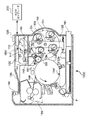
図1は実施例のプリンタ1000の構成例を示す図である。なお、本実施例は、複数の複合機(MFP)、複写機、レーザビームやインクジェットプリンタが接続されるネットワーク環境に適用することができるが、以下では、典型的なプリンタとしてカラーレーザビームプリンタ(以下、単に「プリンタ」と呼ぶ)を例として説明する。また、図1に示すプリンタは、各色成分の画素を8ビットで階調表現した多値データに基づき、600 dpiの記録密度の画像を印刷する。
[Printer]
FIG. 1 is a diagram illustrating a configuration example of a
図1において、プリンタ1000は、外部に接続されるホストコンピュータ200から供給されるプリントデータ(文字コード、画像データ、ページ記述言語(PDL)の記述言語データ等)および制御コードからなる印刷命令を受信して記憶するとともに、受信した印刷命令に従い、文字パターンやイメージなどを形成して、記録紙上にカラー可視像を形成する。フォーマッタ制御部110は、ホストコンピュータから供給される印刷命令を解析して印刷イメージの生成処理を行うとともに、プリンタ1000全体の制御を行う。また、フォーマッタ制御部110は、ユーザの操作・指示を入力し、ユーザへプリンタ1000の状態を通知するための、スイッチおよびLCD表示器などが配され、例えばプリンタ1000の筐体の一部として実装されているオペレーションパネル120と接続されている。
In FIG. 1, the
フォーマッタ制御部110において生成された最終的な印刷イメージは、ビデオ信号VDOとして出力制御部130に読み出される。出力制御部130は、プリンタ1000の各部に配置された各種センサ(図示しない)から状態信号を入力するとともに、光学ユニット140および各種駆動系機構部に対し制御信号を出力して印刷処理を制御し実行する。
The final print image generated by the
給紙カセット161から供給される記録紙Pは、その先端をグリッパ154fにより狭持されて転写ドラム154の外周に保持される。光学ユニット140から出力されるレーザビームによって感光ドラム151上には、四色に色分解された画像の静電潜像がイエロー(Y)、マゼンタ(M)、シアン(C)およびブラック(Bk)の順に形成される。各色の静電潜像は、現像選択機構部152内の対応する現像器Dy、Dm、DcまたはDkによってトナー現像され、現像結果のトナー像が転写ドラム154上の記録紙Pに重畳転写され、記録紙P上に多色画像が形成される。
The leading end of the recording paper P supplied from the
その後、記録紙Pは、転写ドラム154より分離され、定着ユニット155へ搬送される。そして、定着ユニット155によって熱と圧力によりトナー像が定着された記録紙Pは、排紙部159より排紙トレイ部160に排出される。
Thereafter, the recording paper P is separated from the transfer drum 154 and conveyed to the
ここで、各色の現像器Dy、Dm、DcおよびDkは、その両端に回転支軸を有し、それぞれ、その軸を中心に回転可能に現像器選択機構部152に保持されている。これによって、各現像器は、図2に示すように、現像器を選択するために現像器選択機構部152が回転軸152aを中心に回転しても、その姿勢を一定に維持することができる。選択された現像器が現像位置に移動後、支点153bを有する選択機構保持フレーム153がソレノイド153aにより感光ドラム151の方向へ引っ張られ、現像器選択機構部152が感光ドラム151の方向へ移動することで現像処理が行われる。
Here, the developing devices Dy, Dm, Dc, and Dk of the respective colors have rotation support shafts at both ends, and are respectively held by the developing device
また、フォーマッタ制御部110は印刷命令をデバイスに依存するビットマップデータに展開し、出力制御部130は、フォーマッタ制御部110からビットマップデータに対応するビデオ信号VDOを読み出す。このビデオ信号は、レーザドライバ141に入力され半導体レーザ素子を駆動する。半導体レーザ素子から出力されるレーザ光Lは、ビデオ信号VDOに応じてオンオフ制御され、さらに、スキャナモータ143によって高速回転するポリゴンミラー142によって反射され、f-θレンズ144および反射鏡145を介して、帯電器156によって所定の極性に均一に帯電された感光ドラム151上を走査露光する。これにより、感光ドラム151上には、ビデオ信号VDOに対応する静電潜像が形成される。
Also, the
次に、例えばM色の静電潜像がM色の現像器Dmにより現像され、感光体ドラム151上にM色の第一のトナー像が形成される。一方、所定のタイミングで記録紙Pが給紙カセット161から供給され、トナーと反対極性(例えばプラス極性)の転写バイアス電圧が転写ドラム154に印加されることで、記録紙Pが転写ドラム154の表面に静電吸着されるとともに、感光体ドラム151上の第一のトナー像が記録紙Pに転写される。トナー像転写後、感光ドラム151に残留するトナーは、クリーナ157によって除去され、次の色の潜像形成および現像に備える。
Next, for example, the M-color electrostatic latent image is developed by the M-color developing device Dm, and the M-color first toner image is formed on the
以下同様の手順によってC、Y、Bkの順に第二、第三および第四色の静電潜像の走査露光、トナー像の現像および転写が行われる。ただし、第二、第三および第四色の転写時には、前回よりも高いバイアス電圧が転写ドラム154に印加される点で異なる。 Thereafter, scanning exposure of the electrostatic latent images of the second, third and fourth colors, development and transfer of the toner image are performed in the order of C, Y and Bk by the same procedure. However, the second, third and fourth colors are different in that a higher bias voltage is applied to the transfer drum 154 than before.
四色のトナー像が重畳転写された記録紙Pの先端部が分離位置に近づくと、分離爪158が接近し、分離爪158の先端が転写ドラム154の表面に接触し、記録紙Pを転写ドラム154から分離する。分離された記録紙Pは、上述したように、定着ユニット155に搬送され、記録紙上のトナー像が定着された後、排紙トレイ160上に排出される。
When the leading edge of the recording paper P onto which the four color toner images are superimposed and transferred approaches the separation position, the
プリンタ1000は、以上のような画像形成過程を経て600 dpiの解像度で画像を出力する。なお、本実施例において印刷装置として使用可能なプリンタは、カラーレーザビームプリンタに限られず、インクジェットプリンタやサーマルプリンタなど他の方式のカラープリンタでもよいし、モノクロプリンタでもよい。
The
[印刷システム]
図2は実施例の印刷システムの構成例を示すブロック図で、印刷システムは、ホストコンピュータ3000と複数のプリンタ1000、1001、1002、…が通信路2000を介して相互に接続された構成を有する。なお、図2には三台の印刷装置を記載するが、印刷装置の数については問わない。
[Printing system]
FIG. 2 is a block diagram illustrating a configuration example of the printing system of the embodiment. The printing system has a configuration in which a
●フォーマッタ制御部
フォーマッタ制御部110はPDLコントローラなどとも呼ばれ、ホストコンピュータ3000などとの通信を行うネットワークインタフェイス(I/F) 3101、受信データなどを一時的に保持する受信バッファ3103、送信データなどを一時的に保持する送信バッファ3104、印刷データを解析するコマンド解析部3107、印刷制御処理を実行する印刷制御処理部3109、描画処理を実行する描画処理部3105、ページメモリ3106などから構成される。
● Formatter control unit The
ネットワークI/F 3101は、ホストコンピュータ3000などと印刷データの送受信を行う。ただし、ホストコンピュータ3000と印刷装置の接続方法は任意で、LANなどのコンピュータネットワークを介して通信プロトコルとして例えばIEEE1284に準拠した通信を可能にする接続でも、USB (Universal Serial Bus)、やIEEE1394などのシリアルバスを介した接続であってもよい。勿論、通信路2000として赤外線や無線を利用することもできる。
The network I /
ネットワークI/F 3101によって受信された印刷データは受信バッファ3103に逐次蓄積され、必要に応じて、コマンド解析部3107または描画処理部3105によって読み出されて処理される。コマンド解析部3107は、印刷命令体系や印刷ジョブ制御言語に準じた制御プログラムにより構成され、コマンドが文字、図形、イメージなどの描画に関する場合は、その処理を描画処理部3105に指示し、コマンドが給紙選択やリセット命令など描画以外の場合は、その処理を印刷制御処理部3109に指示する。
The print data received by the network I /
描画処理部3105は、文字やイメージの各描画オブジェクトをページメモリ3106内のバンドメモリに逐次展開するYMCKレンダラである。図2に示すカラーレーザビームプリンタの場合、MCYKの順にデバイス依存ビットマップデータをプリンタエンジン3110に送る必要があるが、標準状態では、そのために必要なメモリ容量をすべて確保するわけではない。つまり、描画処理部3105は、1プレーン(1、2または4ビット/画素)の数分の一の容量のメモリ領域をバンドメモリとしてページメモリ3106内に確保し、バンドメモリを繰り返し用いて、プリンタエンジン3110の処理に同期した描画処理を実行する。なお、プリンタエンジン3110は、図2に示す光学ユニット140、感光ドラム151、現像選択機構部152、転写ドラム154、定着ユニット155など上述した画像形成過程を実行する構成全体の総称である。
The
通常は、描画処理部3105による展開処理を、プリンタエンジン3110へのビデオ信号のシッピング処理が追いかけるバンディング制御によってページメモリ3106は管理されるが、充分なメモリ容量がある場合は一頁分のビットマップデータを展開可能なメモリ領域を確保してもよい。
Normally, the
また、一般に、フォーマッタ制御部110は、中央演算処理装置(CPU)、リードオンリメモリ(ROM)、ランダムアクセスメモリ(RAM)などを用いるコンピュータシステムに、フォーマッタ制御部用の制御・処理プログラムを実行させることによって構成される。フォーマッタ制御部110内の各部の処理は、マルチタスクモニタ(リアルタイムOS)の基でタイムシェアリングに処理される構成であってもよいし、各機能ごとに専用のコントローラハードウェアを用意して独立に処理される構成であっても構わない。
In general, the
オペレーションパネル120は、前述したように、ユーザの操作・指示を入力し、ユーザへプリンタ1000の状態を通知するためのものである。出力制御部3108は、バンドメモリ(ページメモリ)3106に展開されたビットマップデータをビデオ信号に変換処理し、プリンタエンジン3110へ転送する。プリンタエンジン3110は、受信したビデオ信号に基づき、記録紙上に可視像を形成する。
As described above, the
●ホストコンピュータ
ホストコンピュータ3000は、プリントデータおよび制御コードからなる印刷データをプリンタ1000に出力する。ホストコンピュータ3000は、入力装置としてのキーボード310やマウス311、表示装置であるディスプレイモニタ320が接続された一つのコンピュータシステムとして構成されている。なお、ホストコンピュータ3000は、中央演算処理装置(CPU)、リードオンリメモリ(ROM)、ランダムアクセスメモリ(RAM)、ハードディスクドライブ(HDD)、各種入出力制御部(I/O)などのハードウェアの基で、Windows(R)などの基本ソフト(OS)がその制御を司り、その基本ソフトの基で、それぞれのアプリケーションソフトウェアやサブシステムプロセスが機能モジュールとして動作する。
Host Computer The
本実施例に関与する機能のみに注目すると、ホストコンピュータ3000の機能部は、アプリケーションソフトウェア301、グラフィックサブシステム302、スプーラ303および印刷装置と通信を行うネットワークインタフェイス3033に区分される。アプリケーションソフトウェア301は、例えばワープロや表計算などのOS上で動作する、一般的なドキュメントを作成するアプリケーションソフトウェアである。
Focusing only on the functions related to the present embodiment, the functional units of the
グラフィックサブシステム302は、OSの機能の一部であるGraphics Device Interface(以後「GDI」と記す)3021、GDI 3021から動的にリンクされるデバイスドライバであるプリンタドライバ3022、バンドスプーラ3023および積算データ3024(例えば、ともにRAMの所定領域に格納される)によって構成される。プリンタドライバ3022は、GDI 3021からDevice Driver Interface(以降「DDI」と記す)3025を介してコールされ、印刷装置に応じた処理を描画オブジェクトごとに行う。本実施例にかかるホストコンピュータ3000は、DDI関数に渡された情報をプリンタが高速に処理可能な印刷命令データ(PDL)形式に変換して直接スプーラ303に送出する場合と、生成した印刷命令データをバンド単位に分割してバンドスプーラ3023に第一のバンドから順に一頁分保持し、頁の最後にまとめてスプーラ303に送出する場合の、二通りの処理が存在する。
The graphics subsystem 302 includes a graphics device interface (hereinafter referred to as “GDI”) 3021 which is a part of the OS function, a
スプーラ303は、OSが管理するスプールファイルシステムで、設定により一頁単位またはジョブ単位で印刷データをスプールファイル3031(例えば、HDDに格納領域が割り当てられる)として格納し、I/F 3032およびネットワークI/F 3033を介して印刷装置に送信する。
The
OSによって、上述した各部の名称や機能的な枠組みが若干異なる場合もあるが、これら名称や枠組みの相違は本実施例の本質には影響しない。例えば、本実施例でスプーラやスプールファイルと呼ぶモジュールは、別のOSにおいてはプリントキューと呼ばれるモジュールを用いて実現可能である。 Although the names and functional frameworks of the above-described parts may differ slightly depending on the OS, differences in these names and frameworks do not affect the essence of the present embodiment. For example, a module called a spooler or a spool file in this embodiment can be realized using a module called a print queue in another OS.
●プリンタドライバの処理
図3はプリンタドライバ3022の処理概要を模式的に示す図で、一般的なドキュメント作成アプリケーションを使って作成したドキュメント4001は、グラフィクス、文字、イメージを含むものとする。
Processing of Printer Driver FIG. 3 is a diagram schematically showing the processing outline of the
ドキュメント4001を印刷する際、まず、OSにインストールされているプリンタドライバ3022に対して、OSを介して、描画命令4002、4003が渡される。プリンタドライバ3022は、初期状態は通常のPDLモード系ドライバと同様に、描画命令ごとに印刷命令(PDL)を生成し、スプーラ303に書き込み、コマンド数やコマンドの種類に応じた所定の計算式で計算したデータサイズを積算データ3024として積算する(S4004)。なお、OSを介してプリンタドライバ3022が受け取る描画命令(DDI関数)は、描画オブジェクトの重なりの、下位のレイヤから順に出力される仕様である。スプーラ303は、一頁分のデータすべてが書き込まれると、スプールファイル3031として蓄えた印刷命令(PDL)および積算データ3024を後述するタスクマネージャに送信し、スプールファイル3031をクリアし、積算データ3024のクリアをプリンタドライバ3023に指示する(S4012)。
When printing the
一方、積算データ3024の値が、予め定めたデータサイズ、コマンド数などを超えた場合は頁単位の処理を、下記のバンド単位の処理に切り替える。なお、図5に示す「矩形描画(イメージの背景)」4021、「イメージ描画」4022および「イメージの実体(画像データ)」4023まではスプーラ303に格納され、「イメージの実体」4023がスプーラ303に出力された時点で積算データ3024が予め定めたデータサイズの閾値を超えたタイミングでバンド単位の処理に切り替えられるものとする。
On the other hand, when the value of the accumulated
プリンタドライバ3022は、上記のタイミングでバンド単位の処理に切り替えると、「イメージの実体」4023以降の描画命令4003に対する印刷命令を生成し、印刷装置が処理するバンド領域ごとに、印刷命令を分けて描画順にバンドスプーラ3023に格納し管理する(S4006)。OSから渡される描画命令4003(DDI関数)は、印刷装置の印刷方向とは無関係に出力されるため、本実施例のように頁の途中からバンド単位の処理に切り替わった場合も、第一のバンドから第N番目のバンドまで頁内のすべてのバンドに対する格納処理が行われる。
When the
格納処理はプリンタドライバ3022内のDDI関数がコールされる度に行われる。もし、バンド単位の処理用に確保した格納領域に空きがなくなった場合は、新たにRAMの領域を確保することで対処する。一頁分の残りに相当する、第一のバンドから第N番目のバンドまでの描画データの格納が終了すると、印刷装置に処理させるバンド順にデータをスプーラ303に書き出し、バンドスプーラ3023をクリアする(S4009)。
The storing process is performed every time the DDI function in the
各バンドデータの先頭には、以降に送出するバンドデータの情報(Band N inf)4011を付加することで、印刷データが頁単位からバンド単位に移行したことを印刷装置に認識させる。スプーラ303は、一頁分の印刷データが書き込まれると、スプーラファイル3031および積算データ3024を後述するタスクマネージャへ送信し、スプールファイル3031をクリアし、積算データ3024のクリアをプリンタドライバ3022に指示する(S4012)。
By adding band data information (Band N inf) 4011 to be transmitted later to the head of each band data, the printing apparatus recognizes that the print data has shifted from page units to band units. When the print data for one page is written, the
●印刷装置のハードウェア構成
図4は印刷装置のハードウェア構成例を示す図である。
FIG. 4 is a diagram illustrating a hardware configuration example of the printing apparatus.
印刷装置のCPU 501は、ROM 502に格納された制御・処理プログラムに従い、RAM 503をワークメモリに利用して印刷装置全体の制御、画像処理を含む演算処理などを行う。ROM 502は、制御・処理プログラムなどが格納されていて、CPU 501は、ROM 502からプログラムを読み出し実行することによって動作する。RAM 503は、ネットワーク2000との送受信データを一時保存する受信バッファ3103、送信バッファ3104、描画された画像データを一時保存するページメモリ3106、CPU 501が演算に必要なデータを一時保存するワークメモリなどとして利用される。これらCPU 501、ROM 502、RAM 503を組み合わせることによって、フォーマット制御部110などが実現される。
The
CPU 501、ROM 502、RAM 503はシステムバス504によって相互に接続され、さらにバスブリッジ506を介して、拡張バス505に接続される。バスブリッジ506によって、システムバス504と拡張バス505は独立に動作可能である。プリンタI/F 507は、RAM 503などに格納された画像データをプリンタエンジン3110へ転送する。
The
ネットワークI/F 3101は、バイセントロインタフェイスであるIEEE1284 I/F 508、および、ネットワークコントローラ509を備える。PHY 511は、ネットワーク2000と接続するための物理トランシーバである。また、MII I/F 512は、PHY 511へLANC 509を接続するためのインタフェイスで、PHY 511との間でハンドシェークのデータ転送を行う。さらに、LANC 509が内蔵する制御部513は、LANC 509内の制御および外部との通信の制御を行う。制御部513は、専用の信号線510によってCPU 501へ割り込みを通知することが可能で、ネットワーク2000とのデータの送受信の終了を通知したりすることが可能である。また、ネットワーク2000上の別の機器からデータパケットを受信し、そのデータパケットから特定のビットパターン検出した場合(以下「特定のパケットを受信」と記す)、CPU 501へその旨を割り込みで通知する。なお、特定のパケットには、マジックパケット(Magic Packet)や、後述する分散処理の開始を示すパケットが含まれ、それらのビットパターンは制御部513に予め保持されている。なお、分散処理の開始を示すパケットのビットパターンは、予めホストコンピュータおよび印刷装置の間で設定されているものとする。なお、本実施例では、この分散処理の開始を示す特定のビットパターンを有するパケットを「Gridパケット」と呼ぶことにする。
The network I /
クロック制御部514は、図示しないクロック供給線によって上記の各モジュールにクロックを分配する。クロック制御部514は、CPU 501から設定可能なレジスタ514aの値によって、一部のモジュールへ供給するクロックの停止(以下「クロック停止」と呼ぶ)、クロック停止の解除、一部のモジュールへ供給するクロックを通常動作時よりも低い周波数にする(以下「クロックダウン」と呼ぶ)、通常動作時の周波数に戻す(以下「クロックアップ」と呼ぶ)などの制御が可能である。
The
●分散処理
図5は印刷システムの分散処理を説明する図である。なお、以下の説明では、タスクマネージャ(TM) 3034およびダイナミックジョブスケジューラ(DJS) 3035は、ホストコンピュータ3000のCPUが実行する基本ソフト上に実装されたソフトウェアによって機能するものとする。また、ブローカおよびリソースマネージャ(RM)は、各印刷装置のCPUが実行する基本ソフト上に実装されたソフトウェアによって機能するものとする。
Distributed Processing FIG. 5 is a diagram for explaining distributed processing of the printing system. In the following description, it is assumed that the task manager (TM) 3034 and the dynamic job scheduler (DJS) 3035 function by software installed on basic software executed by the CPU of the
まず、ホストコンピュータ3000はジョブを開始する。なお、本実施例の場合、ジョブとはプリント動作のことである。ジョブを受信したTM 3034は、ジョブリクエストをDJS 3035に送り、その分析を依頼し、DJS 3035からの分析結果(最適なブローカを示す通知を含む)に基づき、ジョブをブローカ1003、1005および/または1007へ投入する(図5はプリンタ1002のブローカ1007へジョブが投入された状態を示している)。なお、DJS 3035は、定期的にブローカへ状況を問い合わせてリソース(印刷装置の空き状況)の状況および印刷システム全体の状況を常に把握し、最適なブローカを選択する。なお、DJS 3035は、ジョブをハードウエアによって処理するのか、ソフトウェアによって処理するのかの判断もで行う。
First, the
各印刷装置のブローカ1003、1005、1007は、同じ装置のRM 1004、1006、1008からリソースの空き状態などを吸い上げ、DJS 3035に登録する。また、各ブローカは、TM 3034からジョブを投入されると、最適なリソースを探し、そのリソースにRMを介してジョブを投入し、RMからのジョブ完了通知(および処理結果)をTM 3034に通知する。また、各RMは、リソースに異常があれば、その旨を同じ装置のブローカへ通知する。なお、異常とは、他のクライアントからジョブを投入されて、TM 3034から投入される/されたジョブを継続して処理することができない場合などに当たる。
The
図6はTM 3034の処理を示すフローチャートである。
FIG. 6 is a flowchart showing the processing of
TM 3034は、ジョブが投入されるのを待ち(S1101)、ジョブが投入されるとその処理時間を予測する(S1102)。処理時間は、前述した積算データ3024から予測することができる。
The
次に、処理時間の予測結果から分散処理するか否かを判定し(S1103)、分散処理した方が速いと判断した場合は、予め指定された機器にジョブから分割した処理を投入する(S1105)。なお、処理の分割方法は、バンド単位、頁単位などが可能である。勿論、複数の機器に分割した処理を分散投入してもよいし、ある機器ですべてを処理した方が速ければその機器にジョブを丸ごと投入してもよい。 Next, it is determined whether or not to perform distributed processing from the prediction result of processing time (S1103), and when it is determined that distributed processing is faster, processing divided from a job is input to a predesignated device (S1105). ). Note that the process division method may be a band unit, a page unit, or the like. Of course, processing divided into a plurality of devices may be distributed and a job may be submitted to the device if it is faster to process all of the devices.
DJS 3035は、定期的に、ネットワークに接続されたプリンタ1002などに実装されているブローカ1007などへ状況を問い合わせるため、ネットワークに接続されているリソース(印刷装置の空き情報)などの状態を把握し、この把握した情報を内部に保持している。このため、機器を指定する際は、DJS 3035が保持しているネットワーク上のリソース情報を元に、空いている機器を選択し、ジョブを投入することが可能である。
次に、分割した処理を投入した機器から返される処理結果(ここでは、レンダリングされ、ビットマップデータに変換された画像データ)を結合し(S1106)、ジョブに指定されたプリンタに画像を印刷させて(S1107)ジョブを終了する。勿論、一台の機器に丸ごとジョブを投入した場合は処理結果を結合する必要はない。 Next, the processing results (in this case, the image data that has been rendered and converted into bitmap data) returned from the device that has submitted the divided processing are combined (S1106), and the printer specified for the job is allowed to print the image. (S1107) to finish the job. Of course, when the entire job is submitted to one device, it is not necessary to combine the processing results.
また、ステップS1103の判定で、ジョブに指定されたプリンタで処理した方が速い、分散処理した方が速くても予め指定された機器のリソースが他のジョブの処理中で処理の高速化が期待できない、あるいは、ジョブが比較的軽く指定されたプリンタの処理速度で充分処理できる場合などは、ジョブに指定されたプリンタに処理(レンダリングおよびビットマップデータへの変換)(S1104)および画像の印刷(S1107)を行わせ、ジョブを終了する。 Also, in the determination in step S1103, it is expected that the processing specified by the printer designated for the job is faster, and the processing performed by the distributed processing is faster. If it is not possible, or if the job can be processed sufficiently at the processing speed of the printer specified relatively lightly, processing (rendering and conversion to bitmap data) (S1104) and image printing (printing ( S1107) is performed and the job is terminated.
ここでは、TM 3034によってプリンタ1000に分割処理が投入される場合を想定する。TM 3034による分散処理の開始指示に対して、プリンタ1000のCPU 501上で動作するブローカ1003が応答し、次に、同様にCPU 501上で動作するRM 1004が応答する。そして、ブローカ1003は、分割処理の受信が可能であること、および、プリンタ1000のリソースの状況をTM 3034に返信する。この返信に対して、TM 3034はブローカ1003に分割処理を送信する。
Here, it is assumed that division processing is input to the
●分散処理を割り当てる機器の選定
次に、省電力モードを踏まえた分散処理の機器選定を例を挙げて説明する。なお、以下に説明するプリンタは、省電力モードに移行するまでの未使用時間を任意に設定することができる。
● Selection of devices to which distributed processing is allocated Next, an example of selecting devices for distributed processing based on the power saving mode will be described. Note that the printer described below can arbitrarily set the unused time until shifting to the power saving mode.
図7はプリンタ1000〜1005の各状態、および、クライアントPC(ホストコンピュータ)3000からジョブを投入する様子を示す図である。なお、各プリンタに付記する「wake」は当該プリンタが稼働状態を、「sleep」は当該プリンタがスリープ状態(省電力モード)を示している。
FIG. 7 is a diagram illustrating each state of the
プリンタ1000は非動作状態が10分間継続すると省電力モード(スリープ状態)に移行する設定(スリープ設定:10分間)で、現在、未使用状態で八分間経過している。この後二分間、未使用状態が継続するとプリンタ1000は省電力モードに移行する。
The
プリンタ1001は、スリープ設定が60分間で、現在、未使用状態で15分間経過している。従って、プリンタ1002は、省電力モードに移行するまでに45分間も必要とし、今、ジョブを処理させたとしても、再び、未使用状態が15分間継続すれば、現状と同じ条件になる。
The
プリンタ1002は、スリープ設定が60分間で、未使用状態が50分間経過している。従って、この後10分間、非動作状態が継続するとプリンタ1002は省電力モードに移行するが、もし、ジョブを処理させると、再び、未使用状態が50分間継続しなければ、現状と同じ条件にはならない。
The
プリンタ1003および1004は、既に省電力モードに移行している。ただし、プリンタ1005は、通常の稼働状態における消費電力が他のプリンタに比べて充分に小さい、例えば低速機のようなプリンタとする。
The
また、プリンタ1006は、スリープ設定が30分間で、現在、未使用状態で三分間経過している。従って、プリンタ1006は、省電力モードに移行するまで27分間を必要とし、今、ジョブを処理させたとしても、再び、未使用状態が三分間継続すれば、現状と同じ条件になる。
The
以上の各プリンタの機器情報は、サーバ3001上で稼働するDJS 3035によって吸い上げられる。
The above device information of each printer is downloaded by the
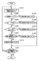
図8は分散処理を割り当てる機器の選定を示すフローチャートで、DJS 3035によって実行される処理である。
FIG. 8 is a flowchart showing selection of a device to which distributed processing is assigned, and is processing executed by the
まず、DJS 3035は、分散処理を割り当てる機器を一台抽出し(S1201)、当該機器の通常の動作における消費電力が閾値th以下か否かを判定する(S1202)。つまり、消費電力が閾値th以下であれば、当該機器を分散処理に使用しても省電力に対する影響が少ない。図7に示す例では、プリンタ1004の消費電力が閾値th未満である。従って、消費電力が閾値th以下の機器は分散処理の対象に加える(S1203)。
First, the
また、消費電力が閾値thを超える機器の場合は、当該機器が、現在、省電力モード状態か否かを判定する(S1204)。省電力モード状態の場合は、省電力モード状態を維持させるために、当該機器を分散処理の対象に加えない(S1205)。図7においては、プリンタ1003が相当する。
In the case of a device whose power consumption exceeds the threshold th, it is determined whether or not the device is currently in a power saving mode (S1204). In the power saving mode state, in order to maintain the power saving mode state, the device is not added to the target of distributed processing (S1205). In FIG. 7, the
また、省電力モード状態ではない機器の場合は、当該機器のスリープ設定時間と未使用状態の継続時間に基づき、分散処理の対象にするか否かを判定する。 Further, in the case of a device that is not in the power saving mode state, it is determined whether or not to be subject to distributed processing based on the sleep setting time of the device and the duration time of the unused state.
まず、省電力モードに移行するまでの時間が五分間以内か否かを判定する(S1206)。例えば、図7に示すプリンタ1000は、あと二分間で省電力モードに移行するので、移行間際の機器と判定し、分散処理の対象に加えない(S1207)。
First, it is determined whether or not the time until shifting to the power saving mode is within 5 minutes (S1206). For example, since the
また、図7に示すプリンタ1001は、省電力モードに移行するまでの時間が45分間あるため、移行間際の機器とは判定せず、続いて、未使用状態の継続時間が30分間以上か否かを判定する(S1208)。プリンタ1001は未使用状態の継続時間は15分間であるから、ジョブを処理させても現状の継続時間に復帰するための時間はそれほど大きくないと判断し、分散処理の対象に加える(S1209)。
In addition, since the
また、図7に示すプリンタ1002は、省電力モードに移行するまでの時間が10分間あるため、移行間際の機器とは判定されず、続いて未使用状態の継続時間を判定する(S1208)。プリンタ1002の未使用状態の継続時間は30分間以上の50分間であるから、ジョブを処理させた後、現状の継続時間に復帰するには大きな時間が必要と判断し、分散処理の対象に加えない(S1210)。
Further, since the
また、プリンタ1005は、省電力モードに移行するまでの時間が27分間あり、未使用状態の継続時間が三分間であるから、移行間際の機器ではなく、かつ、ジョブを処理させても現状の継続時間に復帰するための時間はそれほど大きくないと判断し、分散処理の対象に加える(S1209)。
In addition, the
なお、図8に示す処理は、ステップS1211の判定により、分散処理を割り当てる機器をすべて抽出するまで繰り返す。 Note that the processing shown in FIG. 8 is repeated until all devices to which distributed processing is assigned are extracted according to the determination in step S1211.
従って、各プリンタが図7に示す状態にある場合、DJS 3035は、それらプリンタの機器情報を参照して、プリンタ1001、1004、1005の三台を分散処理の対象として、それらプリンタのブローカを示す情報を、分散処理の要求元であるクライアントPC 3000のTM 3034に通知する。この通知に基づき、クライアントPC 3000のTM 3034は、当該ブローカにプリントジョブなどのジョブを投入する。
Accordingly, when each printer is in the state shown in FIG. 7, the
このように、省電力モードを踏まえた分散処理の機器選定を行うことができる。従って、省電力モードにある機器、および、省電力モードに移行間際の機器を分散処理の対象から外して、省電力モードを効果的に機能させることができる。また、たとえ省電力モードにあっても消費電力が小さい機器や、省電力モードに移行するまでに時間を要する機器(移行間際ではない機器)は、積極的に分散処理の対象として、ジョブの高速処理を実現することができる。 In this way, it is possible to select a device for distributed processing based on the power saving mode. Therefore, the device in the power saving mode and the device just before the transition to the power saving mode can be excluded from the target of distributed processing, and the power saving mode can be effectively functioned. In addition, devices that consume less power even in the power saving mode, or devices that require a long time to enter the power saving mode (devices that are not on the verge of transition) are actively targeted for distributed processing. Processing can be realized.
なお、上記および図8に示した時間の閾値は一例であり、図7に示すシステムの構成に応じて適宜設定することが好ましい。同様に、消費電力の閾値thも、システムに備わる各プリンタの消費電力を考慮して、少なくとも消費電力が最小のプリンタが選定されるように設定すればよい。 Note that the time threshold values described above and illustrated in FIG. 8 are examples, and are preferably set as appropriate according to the configuration of the system illustrated in FIG. Similarly, the power consumption threshold value th may be set so that at least the printer with the smallest power consumption is selected in consideration of the power consumption of each printer provided in the system.
以下、本発明にかかる実施例2の処理を説明する。なお、実施例2において、実施例1と略同様の構成については、同一符号を付して、その詳細説明を省略する。 The processing of the second embodiment according to the present invention will be described below. Note that the same reference numerals in the second embodiment denote the same parts as in the first embodiment, and a detailed description thereof will be omitted.
図9はプリンタ1201〜1204の各状態、および、クライアントPC(ホストコンピュータ)3000からジョブを投入する様子を示す図である。
FIG. 9 is a diagram illustrating each state of the
プリンタ1201がスリープ状態に移行するまでの時間(スリープ移行時間)は30分間、プリンタ1202のスリープ移行時間は10分間、プリンタ1203はスリープ状態、プリンタ1204のスリープ移行時間は三分間である。サーバ3001のDJS 3035は、これらプリンタの機器情報を吸い上げ、分散処理を割り当てる機器を選定する。
The time until the
まず、DJS 3035は、クライアントPC 3000が投入するジョブ処理量を見積もり、当該ジョブを処理量の小さなジョブに分割する準備を行う。また、DJS 3035は、プリンタ1201〜1204のジョブ処理能力を吸い上げ、ジョブ処理量に対する処理時間を算出する。そして、DJS 3035は、処理時間とスリープ移行時間を考慮して、稼働状態のプリンタ1201、1202および1204が省電力モードに移行するまでの時間内に処理可能なジョブ処理量を算出し、プリンタとジョブ処理量(分割ジョブの処理量)の関係をクライアントPC 3000のTM 3034に通知する。TM 3034は、この通知に基づき、分割ジョブを各プリンタに配分する。
First, the
図10は、図9に示す状態にあるプリンタに分割ジョブを配分するためにジョブ処理量を管理するテーブルを示す図で、DJS 3035によって管理されるテーブルである。
FIG. 10 is a diagram showing a table for managing the job processing amount for allocating divided jobs to the printer in the state shown in FIG. 9, and is a table managed by the
プリンタ1201、1202、1204のスリープ移行時間は30分間、10分間、3分間、また、その処理能力は13.3、20、33である。なお、処理能力の単位は、システム固有の処理時間の指標に適したものを用いる。
The sleep transition times of the
ジョブ処理量(分割ジョブ数)は、処理能力とスリープ移行時間(処理が可能な時間)を掛け合わせて算出する値である。プリンタ1201、1202、1204のジョブ量はそれぞれ400、200、100になる。
The job processing amount (number of divided jobs) is a value calculated by multiplying the processing capacity and the sleep transition time (time in which processing is possible). The job amounts of the
このジョブ処理量に基づき、TM 3034は、プリンタ1201にジョブ処理量の4/7(=400/700)程度の割合の分割ジョブを分配し、プリンタ1202および1204に2/7、1/7程度の割合の分割ジョブを分配する。なお、ジョブの分割単位は、処理の種別に固有のもので構わない。例えば、描画処理のように頁ごとに独立した処理であれば、分割割合に見合った頁数の描画処理ジョブを分配すればよい。
Based on this job processing amount,
なお、プリンタ1201、1202、1204は、分配された分割ジョブを終了後、スリープ移行時間が経過するとスリープ状態になる。言い換えれば、分割ジョブの処理は、スリープ移行時間に影響しない。また、通常のプリントやコピージョブが投入された場合、プリンタ1201〜1204は稼働状態に戻り、スリープ移行時間がリセットされることは言うまでもない。
Note that the
[他の実施例]
なお、本発明は、複数の機器(例えばホストコンピュータ、インタフェイス機器、リーダ、プリンタなど)から構成されるシステムに適用しても、一つの機器からなる装置(例えば、複写機、ファクシミリ装置など)に適用してもよい。
[Other Examples]
Note that the present invention can be applied to a system including a plurality of devices (for example, a host computer, an interface device, a reader, and a printer), and a device (for example, a copying machine and a facsimile device) including a single device. You may apply to.
また、本発明の目的は、前述した実施例の機能を実現するソフトウェアのプログラムコードを記録した記憶媒体(または記録媒体)を、システムあるいは装置に供給し、そのシステムあるいは装置のコンピュータ(またはCPUやMPU)が記憶媒体に格納されたプログラムコードを読み出し実行することによっても、達成されることは言うまでもない。この場合、記憶媒体から読み出されたプログラムコード自体が前述した実施例の機能を実現することになり、そのプログラムコードを記憶した記憶媒体は本発明を構成することになる。また、コンピュータが読み出したプログラムコードを実行することにより、前述した実施例の機能が実現されるだけでなく、そのプログラムコードの指示に基づき、コンピュータ上で稼働しているオペレーティングシステム(OS)などが実際の処理の一部または全部を行い、その処理によって前述した実施例の機能が実現される場合も含まれることは言うまでもない。 Also, an object of the present invention is to supply a storage medium (or recording medium) on which a program code of software that realizes the functions of the above-described embodiments is recorded to a system or apparatus, and the computer (or CPU or CPU) of the system or apparatus. Needless to say, this can also be achieved by the MPU) reading and executing the program code stored in the storage medium. In this case, the program code itself read from the storage medium realizes the functions of the above-described embodiments, and the storage medium storing the program code constitutes the present invention. Further, by executing the program code read by the computer, not only the functions of the above-described embodiments are realized, but also an operating system (OS) running on the computer based on the instruction of the program code. It goes without saying that a case where the function of the above-described embodiment is realized by performing part or all of the actual processing and the processing is included.
さらに、記憶媒体から読み出されたプログラムコードが、コンピュータに挿入された機能拡張カードやコンピュータに接続された機能拡張ユニットに備わるメモリに書込まれた後、そのプログラムコードの指示に基づき、その機能拡張カードや機能拡張ユニットに備わるCPUなどが実際の処理の一部または全部を行い、その処理によって前述した実施例の機能が実現される場合も含まれることは言うまでもない。 Furthermore, after the program code read from the storage medium is written into a memory provided in a function expansion card inserted into the computer or a function expansion unit connected to the computer, the function is determined based on the instruction of the program code. Needless to say, the CPU of the expansion card or the function expansion unit performs part or all of the actual processing and the functions of the above-described embodiments are realized by the processing.
本発明を上記記憶媒体に適用する場合、その記憶媒体には、先に説明したフローチャートに対応するプログラムコードが格納されることになる。 When the present invention is applied to the storage medium, the storage medium stores program codes corresponding to the flowcharts described above.
Claims (7)
前記複数の機器の機器情報および動作状況を取得する取得手段と、
前記機器から取得した機器情報が前記機器の通常動作における消費電力が閾値以下を示す場合は、当該機器の省電力モードに関する動作状況を判定することなく、当該機器を前記分散処理の対象機器として選択し、前記機器情報が前記機器の通常動作における消費電力が前記閾値を超えることを示し、当該機器が省電力モードにある場合は、当該機器を分散処理の対象機器として選択しない選択手段とを有することを特徴とする情報処理装置。 An information processing apparatus for managing distributed processing by a plurality of devices having a power saving mode connected to a computer network,
Obtaining means for obtaining device information and operation status of the plurality of devices;
When the device information acquired from the device indicates that the power consumption in the normal operation of the device is less than or equal to the threshold, the device is selected as the target device for the distributed processing without determining the operation status related to the power saving mode of the device. And the device information indicates that the power consumption in the normal operation of the device exceeds the threshold, and when the device is in the power saving mode, the device information includes a selection unit that does not select the device as a target device for distributed processing. An information processing apparatus characterized by that.
前記複数の機器の機器情報および動作状況を取得し、
前記機器から取得した機器情報が前記機器の通常動作における消費電力が閾値以下を示す場合は、当該機器の省電力モードに関する動作状況を判定することなく、当該機器を前記分散処理の対象機器として選択し、
前記機器情報が前記機器の通常動作における消費電力が前記閾値を超えることを示し、当該機器が省電力モードにある場合は、当該機器を分散処理の対象機器として選択しないことを特徴とする制御方法。 A method for controlling an information processing apparatus for managing distributed processing by a plurality of devices connected to a computer network and having a power saving mode,
Acquire device information and operation status of the plurality of devices,
When the device information acquired from the device indicates that the power consumption in the normal operation of the device is less than or equal to the threshold, the device is selected as the target device for the distributed processing without determining the operation status related to the power saving mode of the device. And
The device information indicates that power consumption in normal operation of the device exceeds the threshold value, and when the device is in a power saving mode, the device is not selected as a target device for distributed processing. .
Priority Applications (3)
| Application Number | Priority Date | Filing Date | Title |
|---|---|---|---|
| JP2005168409A JP4708869B2 (en) | 2005-06-08 | 2005-06-08 | Information processing apparatus and control method thereof |
| US11/449,319 US7936466B2 (en) | 2005-06-08 | 2006-06-08 | Information processing apparatus and its control method for managing distributed processing of at least one of the device information and operation states |
| US13/070,973 US8472043B2 (en) | 2005-06-08 | 2011-03-24 | Information processing apparatus and its control method for managing distributed processing |
Applications Claiming Priority (1)
| Application Number | Priority Date | Filing Date | Title |
|---|---|---|---|
| JP2005168409A JP4708869B2 (en) | 2005-06-08 | 2005-06-08 | Information processing apparatus and control method thereof |
Publications (3)
| Publication Number | Publication Date |
|---|---|
| JP2006343955A JP2006343955A (en) | 2006-12-21 |
| JP2006343955A5 JP2006343955A5 (en) | 2008-07-24 |
| JP4708869B2 true JP4708869B2 (en) | 2011-06-22 |
Family
ID=37523821
Family Applications (1)
| Application Number | Title | Priority Date | Filing Date |
|---|---|---|---|
| JP2005168409A Expired - Fee Related JP4708869B2 (en) | 2005-06-08 | 2005-06-08 | Information processing apparatus and control method thereof |
Country Status (2)
| Country | Link |
|---|---|
| US (2) | US7936466B2 (en) |
| JP (1) | JP4708869B2 (en) |
Families Citing this family (18)
| Publication number | Priority date | Publication date | Assignee | Title |
|---|---|---|---|---|
| US20080170260A1 (en) * | 2003-03-19 | 2008-07-17 | Michael Haller | Output transform brokerage service |
| JP4708869B2 (en) * | 2005-06-08 | 2011-06-22 | キヤノン株式会社 | Information processing apparatus and control method thereof |
| JP2008293278A (en) * | 2007-05-24 | 2008-12-04 | Fujitsu Ltd | Distributed processing program, distributed processor, and the distributed processing method |
| US8248629B2 (en) * | 2007-06-21 | 2012-08-21 | Kyocera Mita Corporation | Image forming apparatus with a power mode control section for allocating a printout for a reserved low-key print setting job |
| JP4850798B2 (en) * | 2007-08-29 | 2012-01-11 | 富士通株式会社 | Method and apparatus for distributing processing to a plurality of processing units |
| JP4584296B2 (en) * | 2007-10-29 | 2010-11-17 | 株式会社沖データ | Image processing device |
| JP5279516B2 (en) * | 2009-01-09 | 2013-09-04 | キヤノン株式会社 | Information processing apparatus, display control method, and program |
| JP5274297B2 (en) * | 2009-02-20 | 2013-08-28 | キヤノン株式会社 | Management device, control method thereof, and program |
| US20100228951A1 (en) * | 2009-03-05 | 2010-09-09 | Xerox Corporation | Parallel processing management framework |
| JP5786870B2 (en) | 2011-02-02 | 2015-09-30 | 日本電気株式会社 | Distributed system, apparatus, method and program |
| JP5652289B2 (en) * | 2011-03-25 | 2015-01-14 | コニカミノルタ株式会社 | Image processing system and image processing control apparatus |
| JP5967979B2 (en) * | 2012-03-05 | 2016-08-10 | キヤノン株式会社 | Information processing apparatus, information processing system control method, information processing apparatus control method, and program |
| KR20140043638A (en) * | 2012-10-02 | 2014-04-10 | 삼성전자주식회사 | Image forming apparatus and method for image forming |
| JP2014115687A (en) * | 2012-12-06 | 2014-06-26 | Canon Inc | Data processing apparatus, method for controlling data processing apparatus, and program |
| JP2014211767A (en) * | 2013-04-18 | 2014-11-13 | 富士通株式会社 | Information processing system, control apparatus, and method of controlling information processing system |
| JP2015026251A (en) * | 2013-07-26 | 2015-02-05 | キヤノン株式会社 | Information processing device, control method for information processing device, and program |
| JP6708106B2 (en) | 2016-11-30 | 2020-06-10 | 京セラドキュメントソリューションズ株式会社 | Information processing apparatus, information processing system, and information processing method |
| US11960782B1 (en) | 2023-06-09 | 2024-04-16 | Kyocera Document Solutions Inc. | Information processing system, image forming system, and information processing method for restoring old version of task file via image forming workflow |
Citations (2)
| Publication number | Priority date | Publication date | Assignee | Title |
|---|---|---|---|---|
| JP2003150363A (en) * | 2001-11-19 | 2003-05-23 | Minolta Co Ltd | Program, management method and management device for network system including printer |
| JP2004046774A (en) * | 2002-05-22 | 2004-02-12 | Sharp Corp | Print server, print system, print job management method, program, and recording medium |
Family Cites Families (14)
| Publication number | Priority date | Publication date | Assignee | Title |
|---|---|---|---|---|
| US5287194A (en) * | 1992-11-25 | 1994-02-15 | Xerox Corporation | Distributed printing |
| DE69434717T2 (en) * | 1993-12-09 | 2007-04-12 | Canon K.K. | Data processing device operating as a host and method for controlling the data processing device |
| JP3610116B2 (en) * | 1994-04-14 | 2005-01-12 | キヤノン株式会社 | Image recording device |
| JP3598791B2 (en) * | 1997-03-28 | 2004-12-08 | セイコーエプソン株式会社 | Network system, printer |
| EP1146417A4 (en) * | 1999-11-16 | 2003-06-18 | Seiko Epson Corp | Printer system, printer control method, and recording medium |
| US7116434B2 (en) * | 2000-08-10 | 2006-10-03 | Canon Kabushiki Kaisha | Controlling a cluster operation |
| JP2002219842A (en) * | 2001-01-25 | 2002-08-06 | Fujitsu Ltd | Printer and method of controlling power saving |
| US6795829B2 (en) * | 2001-06-04 | 2004-09-21 | Hewlett-Packard Development Company, L.P. | Method for building a peripheral information database |
| US7382474B2 (en) * | 2001-09-05 | 2008-06-03 | Minolta Co., Ltd. | Printer management method and management system |
| JP2004062359A (en) * | 2002-07-26 | 2004-02-26 | Canon Inc | Print processing system |
| US7327482B2 (en) * | 2002-10-15 | 2008-02-05 | Sharp Laboratories Of America, Inc. | Integrated printer monitoring |
| JP2005352694A (en) * | 2004-06-09 | 2005-12-22 | Canon Inc | Printing device, printing method, information processing device, and control method thereof |
| US7742185B2 (en) * | 2004-08-23 | 2010-06-22 | Xerox Corporation | Print sequence scheduling for reliability |
| JP4708869B2 (en) * | 2005-06-08 | 2011-06-22 | キヤノン株式会社 | Information processing apparatus and control method thereof |
-
2005
- 2005-06-08 JP JP2005168409A patent/JP4708869B2/en not_active Expired - Fee Related
-
2006
- 2006-06-08 US US11/449,319 patent/US7936466B2/en not_active Expired - Fee Related
-
2011
- 2011-03-24 US US13/070,973 patent/US8472043B2/en not_active Expired - Fee Related
Patent Citations (2)
| Publication number | Priority date | Publication date | Assignee | Title |
|---|---|---|---|---|
| JP2003150363A (en) * | 2001-11-19 | 2003-05-23 | Minolta Co Ltd | Program, management method and management device for network system including printer |
| JP2004046774A (en) * | 2002-05-22 | 2004-02-12 | Sharp Corp | Print server, print system, print job management method, program, and recording medium |
Also Published As
| Publication number | Publication date |
|---|---|
| US7936466B2 (en) | 2011-05-03 |
| US8472043B2 (en) | 2013-06-25 |
| JP2006343955A (en) | 2006-12-21 |
| US20110170130A1 (en) | 2011-07-14 |
| US20060279766A1 (en) | 2006-12-14 |
Similar Documents
| Publication | Publication Date | Title |
|---|---|---|
| JP4708869B2 (en) | Information processing apparatus and control method thereof | |
| JP3977356B2 (en) | Information processing apparatus and control method thereof | |
| KR100757154B1 (en) | Information processing apparatus and its control method | |
| JP3826038B2 (en) | Printing system, printing method therefor, and printing apparatus | |
| JP4736761B2 (en) | Printing device | |
| JP5333259B2 (en) | Image forming apparatus, program, and image forming method | |
| JP2007069357A (en) | Printing system, printer and printing method | |
| JP2009241475A (en) | Image forming apparatus and image forming method and program | |
| US20050275883A1 (en) | Information processing apparatus and its control method | |
| US20030011819A1 (en) | Information processing device, information processing method, printing system, computer program and memory medium | |
| JP3962606B2 (en) | Printing command generation apparatus and method, printing apparatus and control method thereof, information processing apparatus, and printing system | |
| JP4418642B2 (en) | HOST DEVICE, PRINTING DEVICE, PRINTING SYSTEM HAVING THEM, PRINT CONTROL METHOD, AND PROGRAM THEREOF | |
| JP2009214348A (en) | Image processing apparatus, image processing system and image processing program | |
| JP2007140952A (en) | Distributed processing system and its processing method | |
| JP5857594B2 (en) | Distributed printing system and printing apparatus | |
| JP4418573B2 (en) | Image output control device, image output control method, and storage medium | |
| JP4412718B2 (en) | Information processing apparatus and control method thereof | |
| JP2006163870A (en) | Image forming apparatus | |
| JP2006235813A (en) | Print system | |
| JP2004326266A (en) | Print control method, information processing device, and printer | |
| JP2001282498A (en) | Information processor, information processing method and storage medium | |
| JP2003341152A (en) | Printing controlling unit, printing controlling method, printing system, and program | |
| JP2005169671A (en) | Data processing apparatus, printing controlling method, storage medium with computer readable program stored, and program | |
| JP2005349772A (en) | Printing device and its control method | |
| JPH07334321A (en) | Printer and controller, and control method for printer |
Legal Events
| Date | Code | Title | Description |
|---|---|---|---|
| A521 | Written amendment |
Free format text: JAPANESE INTERMEDIATE CODE: A523 Effective date: 20080606 |
|
| A621 | Written request for application examination |
Free format text: JAPANESE INTERMEDIATE CODE: A621 Effective date: 20080606 |
|
| A977 | Report on retrieval |
Free format text: JAPANESE INTERMEDIATE CODE: A971007 Effective date: 20100812 |
|
| A131 | Notification of reasons for refusal |
Free format text: JAPANESE INTERMEDIATE CODE: A131 Effective date: 20100827 |
|
| A521 | Written amendment |
Free format text: JAPANESE INTERMEDIATE CODE: A523 Effective date: 20101025 |
|
| A01 | Written decision to grant a patent or to grant a registration (utility model) |
Free format text: JAPANESE INTERMEDIATE CODE: A01 Effective date: 20110308 |
|
| A61 | First payment of annual fees (during grant procedure) |
Free format text: JAPANESE INTERMEDIATE CODE: A61 Effective date: 20110317 |
|
| LAPS | Cancellation because of no payment of annual fees |