JP4706648B2 - Electric vehicle, charging state estimation method, and computer-readable recording medium recording a program for causing a computer to execute the charging state estimation method - Google Patents
Electric vehicle, charging state estimation method, and computer-readable recording medium recording a program for causing a computer to execute the charging state estimation method Download PDFInfo
- Publication number
- JP4706648B2 JP4706648B2 JP2007055795A JP2007055795A JP4706648B2 JP 4706648 B2 JP4706648 B2 JP 4706648B2 JP 2007055795 A JP2007055795 A JP 2007055795A JP 2007055795 A JP2007055795 A JP 2007055795A JP 4706648 B2 JP4706648 B2 JP 4706648B2
- Authority
- JP
- Japan
- Prior art keywords
- power storage
- storage device
- power
- voltage
- charging
- Prior art date
- Legal status (The legal status is an assumption and is not a legal conclusion. Google has not performed a legal analysis and makes no representation as to the accuracy of the status listed.)
- Active
Links
Images


Classifications
-
- H—ELECTRICITY
- H01—ELECTRIC ELEMENTS
- H01M—PROCESSES OR MEANS, e.g. BATTERIES, FOR THE DIRECT CONVERSION OF CHEMICAL ENERGY INTO ELECTRICAL ENERGY
- H01M10/00—Secondary cells; Manufacture thereof
- H01M10/42—Methods or arrangements for servicing or maintenance of secondary cells or secondary half-cells
- H01M10/48—Accumulators combined with arrangements for measuring, testing or indicating the condition of cells, e.g. the level or density of the electrolyte
- H01M10/482—Accumulators combined with arrangements for measuring, testing or indicating the condition of cells, e.g. the level or density of the electrolyte for several batteries or cells simultaneously or sequentially
-
- B—PERFORMING OPERATIONS; TRANSPORTING
- B60—VEHICLES IN GENERAL
- B60L—PROPULSION OF ELECTRICALLY-PROPELLED VEHICLES; SUPPLYING ELECTRIC POWER FOR AUXILIARY EQUIPMENT OF ELECTRICALLY-PROPELLED VEHICLES; ELECTRODYNAMIC BRAKE SYSTEMS FOR VEHICLES IN GENERAL; MAGNETIC SUSPENSION OR LEVITATION FOR VEHICLES; MONITORING OPERATING VARIABLES OF ELECTRICALLY-PROPELLED VEHICLES; ELECTRIC SAFETY DEVICES FOR ELECTRICALLY-PROPELLED VEHICLES
- B60L58/00—Methods or circuit arrangements for monitoring or controlling batteries or fuel cells, specially adapted for electric vehicles
- B60L58/10—Methods or circuit arrangements for monitoring or controlling batteries or fuel cells, specially adapted for electric vehicles for monitoring or controlling batteries
- B60L58/12—Methods or circuit arrangements for monitoring or controlling batteries or fuel cells, specially adapted for electric vehicles for monitoring or controlling batteries responding to state of charge [SoC]
-
- B—PERFORMING OPERATIONS; TRANSPORTING
- B60—VEHICLES IN GENERAL
- B60L—PROPULSION OF ELECTRICALLY-PROPELLED VEHICLES; SUPPLYING ELECTRIC POWER FOR AUXILIARY EQUIPMENT OF ELECTRICALLY-PROPELLED VEHICLES; ELECTRODYNAMIC BRAKE SYSTEMS FOR VEHICLES IN GENERAL; MAGNETIC SUSPENSION OR LEVITATION FOR VEHICLES; MONITORING OPERATING VARIABLES OF ELECTRICALLY-PROPELLED VEHICLES; ELECTRIC SAFETY DEVICES FOR ELECTRICALLY-PROPELLED VEHICLES
- B60L53/00—Methods of charging batteries, specially adapted for electric vehicles; Charging stations or on-board charging equipment therefor; Exchange of energy storage elements in electric vehicles
- B60L53/50—Charging stations characterised by energy-storage or power-generation means
- B60L53/53—Batteries
-
- B—PERFORMING OPERATIONS; TRANSPORTING
- B60—VEHICLES IN GENERAL
- B60L—PROPULSION OF ELECTRICALLY-PROPELLED VEHICLES; SUPPLYING ELECTRIC POWER FOR AUXILIARY EQUIPMENT OF ELECTRICALLY-PROPELLED VEHICLES; ELECTRODYNAMIC BRAKE SYSTEMS FOR VEHICLES IN GENERAL; MAGNETIC SUSPENSION OR LEVITATION FOR VEHICLES; MONITORING OPERATING VARIABLES OF ELECTRICALLY-PROPELLED VEHICLES; ELECTRIC SAFETY DEVICES FOR ELECTRICALLY-PROPELLED VEHICLES
- B60L58/00—Methods or circuit arrangements for monitoring or controlling batteries or fuel cells, specially adapted for electric vehicles
- B60L58/10—Methods or circuit arrangements for monitoring or controlling batteries or fuel cells, specially adapted for electric vehicles for monitoring or controlling batteries
- B60L58/18—Methods or circuit arrangements for monitoring or controlling batteries or fuel cells, specially adapted for electric vehicles for monitoring or controlling batteries of two or more battery modules
- B60L58/20—Methods or circuit arrangements for monitoring or controlling batteries or fuel cells, specially adapted for electric vehicles for monitoring or controlling batteries of two or more battery modules having different nominal voltages
-
- G—PHYSICS
- G01—MEASURING; TESTING
- G01R—MEASURING ELECTRIC VARIABLES; MEASURING MAGNETIC VARIABLES
- G01R31/00—Arrangements for testing electric properties; Arrangements for locating electric faults; Arrangements for electrical testing characterised by what is being tested not provided for elsewhere
- G01R31/36—Arrangements for testing, measuring or monitoring the electrical condition of accumulators or electric batteries, e.g. capacity or state of charge [SoC]
- G01R31/392—Determining battery ageing or deterioration, e.g. state of health
-
- H—ELECTRICITY
- H01—ELECTRIC ELEMENTS
- H01M—PROCESSES OR MEANS, e.g. BATTERIES, FOR THE DIRECT CONVERSION OF CHEMICAL ENERGY INTO ELECTRICAL ENERGY
- H01M10/00—Secondary cells; Manufacture thereof
- H01M10/42—Methods or arrangements for servicing or maintenance of secondary cells or secondary half-cells
- H01M10/44—Methods for charging or discharging
- H01M10/441—Methods for charging or discharging for several batteries or cells simultaneously or sequentially
-
- B—PERFORMING OPERATIONS; TRANSPORTING
- B60—VEHICLES IN GENERAL
- B60L—PROPULSION OF ELECTRICALLY-PROPELLED VEHICLES; SUPPLYING ELECTRIC POWER FOR AUXILIARY EQUIPMENT OF ELECTRICALLY-PROPELLED VEHICLES; ELECTRODYNAMIC BRAKE SYSTEMS FOR VEHICLES IN GENERAL; MAGNETIC SUSPENSION OR LEVITATION FOR VEHICLES; MONITORING OPERATING VARIABLES OF ELECTRICALLY-PROPELLED VEHICLES; ELECTRIC SAFETY DEVICES FOR ELECTRICALLY-PROPELLED VEHICLES
- B60L2240/00—Control parameters of input or output; Target parameters
- B60L2240/40—Drive Train control parameters
- B60L2240/54—Drive Train control parameters related to batteries
- B60L2240/547—Voltage
-
- B—PERFORMING OPERATIONS; TRANSPORTING
- B60—VEHICLES IN GENERAL
- B60L—PROPULSION OF ELECTRICALLY-PROPELLED VEHICLES; SUPPLYING ELECTRIC POWER FOR AUXILIARY EQUIPMENT OF ELECTRICALLY-PROPELLED VEHICLES; ELECTRODYNAMIC BRAKE SYSTEMS FOR VEHICLES IN GENERAL; MAGNETIC SUSPENSION OR LEVITATION FOR VEHICLES; MONITORING OPERATING VARIABLES OF ELECTRICALLY-PROPELLED VEHICLES; ELECTRIC SAFETY DEVICES FOR ELECTRICALLY-PROPELLED VEHICLES
- B60L2240/00—Control parameters of input or output; Target parameters
- B60L2240/40—Drive Train control parameters
- B60L2240/54—Drive Train control parameters related to batteries
- B60L2240/549—Current
-
- G—PHYSICS
- G01—MEASURING; TESTING
- G01R—MEASURING ELECTRIC VARIABLES; MEASURING MAGNETIC VARIABLES
- G01R31/00—Arrangements for testing electric properties; Arrangements for locating electric faults; Arrangements for electrical testing characterised by what is being tested not provided for elsewhere
- G01R31/36—Arrangements for testing, measuring or monitoring the electrical condition of accumulators or electric batteries, e.g. capacity or state of charge [SoC]
- G01R31/3644—Constructional arrangements
- G01R31/3648—Constructional arrangements comprising digital calculation means, e.g. for performing an algorithm
-
- Y—GENERAL TAGGING OF NEW TECHNOLOGICAL DEVELOPMENTS; GENERAL TAGGING OF CROSS-SECTIONAL TECHNOLOGIES SPANNING OVER SEVERAL SECTIONS OF THE IPC; TECHNICAL SUBJECTS COVERED BY FORMER USPC CROSS-REFERENCE ART COLLECTIONS [XRACs] AND DIGESTS
- Y02—TECHNOLOGIES OR APPLICATIONS FOR MITIGATION OR ADAPTATION AGAINST CLIMATE CHANGE
- Y02E—REDUCTION OF GREENHOUSE GAS [GHG] EMISSIONS, RELATED TO ENERGY GENERATION, TRANSMISSION OR DISTRIBUTION
- Y02E60/00—Enabling technologies; Technologies with a potential or indirect contribution to GHG emissions mitigation
- Y02E60/10—Energy storage using batteries
-
- Y—GENERAL TAGGING OF NEW TECHNOLOGICAL DEVELOPMENTS; GENERAL TAGGING OF CROSS-SECTIONAL TECHNOLOGIES SPANNING OVER SEVERAL SECTIONS OF THE IPC; TECHNICAL SUBJECTS COVERED BY FORMER USPC CROSS-REFERENCE ART COLLECTIONS [XRACs] AND DIGESTS
- Y02—TECHNOLOGIES OR APPLICATIONS FOR MITIGATION OR ADAPTATION AGAINST CLIMATE CHANGE
- Y02T—CLIMATE CHANGE MITIGATION TECHNOLOGIES RELATED TO TRANSPORTATION
- Y02T10/00—Road transport of goods or passengers
- Y02T10/60—Other road transportation technologies with climate change mitigation effect
- Y02T10/70—Energy storage systems for electromobility, e.g. batteries
-
- Y—GENERAL TAGGING OF NEW TECHNOLOGICAL DEVELOPMENTS; GENERAL TAGGING OF CROSS-SECTIONAL TECHNOLOGIES SPANNING OVER SEVERAL SECTIONS OF THE IPC; TECHNICAL SUBJECTS COVERED BY FORMER USPC CROSS-REFERENCE ART COLLECTIONS [XRACs] AND DIGESTS
- Y02—TECHNOLOGIES OR APPLICATIONS FOR MITIGATION OR ADAPTATION AGAINST CLIMATE CHANGE
- Y02T—CLIMATE CHANGE MITIGATION TECHNOLOGIES RELATED TO TRANSPORTATION
- Y02T10/00—Road transport of goods or passengers
- Y02T10/60—Other road transportation technologies with climate change mitigation effect
- Y02T10/7072—Electromobility specific charging systems or methods for batteries, ultracapacitors, supercapacitors or double-layer capacitors
-
- Y—GENERAL TAGGING OF NEW TECHNOLOGICAL DEVELOPMENTS; GENERAL TAGGING OF CROSS-SECTIONAL TECHNOLOGIES SPANNING OVER SEVERAL SECTIONS OF THE IPC; TECHNICAL SUBJECTS COVERED BY FORMER USPC CROSS-REFERENCE ART COLLECTIONS [XRACs] AND DIGESTS
- Y02—TECHNOLOGIES OR APPLICATIONS FOR MITIGATION OR ADAPTATION AGAINST CLIMATE CHANGE
- Y02T—CLIMATE CHANGE MITIGATION TECHNOLOGIES RELATED TO TRANSPORTATION
- Y02T90/00—Enabling technologies or technologies with a potential or indirect contribution to GHG emissions mitigation
- Y02T90/10—Technologies relating to charging of electric vehicles
- Y02T90/12—Electric charging stations
-
- Y—GENERAL TAGGING OF NEW TECHNOLOGICAL DEVELOPMENTS; GENERAL TAGGING OF CROSS-SECTIONAL TECHNOLOGIES SPANNING OVER SEVERAL SECTIONS OF THE IPC; TECHNICAL SUBJECTS COVERED BY FORMER USPC CROSS-REFERENCE ART COLLECTIONS [XRACs] AND DIGESTS
- Y02—TECHNOLOGIES OR APPLICATIONS FOR MITIGATION OR ADAPTATION AGAINST CLIMATE CHANGE
- Y02T—CLIMATE CHANGE MITIGATION TECHNOLOGIES RELATED TO TRANSPORTATION
- Y02T90/00—Enabling technologies or technologies with a potential or indirect contribution to GHG emissions mitigation
- Y02T90/10—Technologies relating to charging of electric vehicles
- Y02T90/14—Plug-in electric vehicles
Landscapes
- Engineering & Computer Science (AREA)
- Power Engineering (AREA)
- Mechanical Engineering (AREA)
- Transportation (AREA)
- Manufacturing & Machinery (AREA)
- Chemical & Material Sciences (AREA)
- Chemical Kinetics & Catalysis (AREA)
- Electrochemistry (AREA)
- General Chemical & Material Sciences (AREA)
- Sustainable Energy (AREA)
- Sustainable Development (AREA)
- Life Sciences & Earth Sciences (AREA)
- Physics & Mathematics (AREA)
- General Physics & Mathematics (AREA)
- Electric Propulsion And Braking For Vehicles (AREA)
- Secondary Cells (AREA)
- Tests Of Electric Status Of Batteries (AREA)
- Charge And Discharge Circuits For Batteries Or The Like (AREA)
Description
この発明は、電動車両、充電状態推定方法および充電状態推定方法をコンピュータに実行させるためのプログラムを記録したコンピュータ読取可能な記録媒体に関し、特に、電動車両に搭載された蓄電装置の充電状態を推定する技術に関する。 The present invention relates to an electric vehicle, a charging state estimation method, and a computer-readable recording medium storing a program for causing a computer to execute the charging state estimation method, and in particular, estimates a charging state of a power storage device mounted on the electric vehicle. Related to technology.
ハイブリッド車両(Hybrid Vehicle)や電気自動車(Electric Vehicle)など電動機を用いて走行可能な電動車両においては、電動機に電力を供給する蓄電装置として、リチウムイオン電池やニッケル水素電池などの二次電池や、大容量の電気二重層キャパシタなどが用いられる。蓄電装置の充電状態を示す状態量としては、SOC(State of Charge)が一般的に用いられ、満充電状態をSOC=100%とし、充電量0の状態をSOC=0%として、蓄電装置の充電状態が表わされる(以下、充電状態を単に「SOC」とも称する。)。
In an electric vehicle that can run using an electric motor such as a hybrid vehicle or an electric vehicle, a secondary battery such as a lithium ion battery or a nickel metal hydride battery is used as a power storage device that supplies electric power to the electric motor. A large-capacity electric double layer capacitor or the like is used. As the state quantity indicating the state of charge of the power storage device, SOC (State of Charge) is generally used. The full charge state is set to SOC = 100%, and the state of
特開2000−258513号公報は、二次電池のSOCを精度よく算出可能なSOC演算方法を開示する。このSOC演算方法では、電池に関して予め与えられる所定抵抗値を電池温度に基づき補正することによって電池の内部抵抗が算出される。そして、その算出された内部抵抗により定まる電池の電圧電流特性に基づいて開放端電圧(以下「OCV:Open Circuit Voltage」とも称する。)が算出され、OCVとSOCとの相間を示すOCV対SOC相関を用いて、算出されたOCVに基づいてSOCが算出される(特許文献1参照)。
しかしながら、特開2000−258513号公報に記載のSOC演算方法は、車両の走行中を含め車両電源がオンされてからオフされるまで繰返しSOC演算を行なうものであり、外乱の影響を大きく受ける。 However, the SOC calculation method described in Japanese Patent Application Laid-Open No. 2000-258513 repeatedly performs SOC calculation from when the vehicle power source is turned on until it is turned off, including when the vehicle is running, and is greatly affected by disturbance.
たとえば、電池の電圧Vは、内部抵抗のほかいわゆる分極電圧の影響も受けるところ、分極電圧は、頻繁に繰返される充放電の履歴により変化し、OCVの算出精度に影響を与える。なお、分極は、SOCの制御域から大きく離れるように充放電を行なうことにより解消し得ることが知られている。 For example, the voltage V of the battery is affected by so-called polarization voltage in addition to internal resistance. However, the polarization voltage changes due to repeated charge / discharge history, and affects the calculation accuracy of OCV. It is known that polarization can be eliminated by charging and discharging so as to be far away from the SOC control range.
また、車両走行中は周囲環境も大きく変化するので、上記公報に記載のSOC演算方法は、その点でも外乱の影響を大きく受け、SOC推定精度が低下する可能性がある。 In addition, since the surrounding environment changes greatly while the vehicle is traveling, the SOC calculation method described in the above publication is also greatly affected by disturbances in this respect, and the SOC estimation accuracy may be reduced.
それゆえに、この発明の目的は、車両走行用の蓄電装置のSOCを高精度に推定可能な電動車両を提供することである。 SUMMARY OF THE INVENTION Therefore, an object of the present invention is to provide an electric vehicle capable of estimating the SOC of a power storage device for vehicle travel with high accuracy.
また、この発明の別の目的は、電動車両に搭載された車両走行用の蓄電装置のSOCをより高精度に推定可能な充電状態推定方法を提供することである。 Another object of the present invention is to provide a state of charge estimation method capable of estimating the SOC of a power storage device for vehicle travel mounted on an electric vehicle with higher accuracy.
また、この発明の別の目的は、電動車両に搭載された車両走行用の蓄電装置のSOCをより高精度に推定可能な充電状態推定方法をコンピュータに実行させるためのプログラムを記録したコンピュータ読取可能な記録媒体を提供することである。 Another object of the present invention is a computer-readable recording of a program for causing a computer to execute a charging state estimation method capable of estimating the SOC of a power storage device for vehicle travel mounted on an electric vehicle with higher accuracy. Is to provide a simple recording medium.
この発明によれば、電動車両は、充放電可能な第1の蓄電装置と、充電装置と、電力装置と、電力装置を制御する制御装置とを備える。充電装置は、車両外部の電源から第1の蓄電装置を充電可能なように構成される。電力装置は、第1の蓄電装置と電力を授受可能なように構成される。制御装置は、充放電制御部と、第1および第2の演算部と、充電状態推定部とを含む。充放電制御部は、充電装置による第1の蓄電装置の充電が要求されると、第1の蓄電装置と電力装置との間で電力を授受するように電力装置を制御する。第1の演算部は、第1の蓄電装置と電力装置との間で電力が授受されているときの第1の蓄電装置の電圧および電流に基づいて、電圧と電流との相関関係を示す電圧電流特性を算出する。第2の演算部は、第1の演算部により算出された電圧電流特性に基づいて第1の蓄電装置の開放端電圧を算出する。充電状態推定部は、予め設定された第1の蓄電装置の開放端電圧と充電状態との相関関係を用いて、第2の演算部により算出された開放端電圧に基づいて第1の蓄電装置の充電状態を推定する。 According to this invention, the electric vehicle includes the first power storage device that can be charged and discharged, the charging device, the power device, and the control device that controls the power device. The charging device is configured to be able to charge the first power storage device from a power source external to the vehicle. The power device is configured to be able to exchange power with the first power storage device. The control device includes a charge / discharge control unit, first and second calculation units, and a charge state estimation unit. When charging of the first power storage device by the charging device is requested, the charge / discharge control unit controls the power device so as to transfer power between the first power storage device and the power device. The first computing unit is a voltage indicating a correlation between the voltage and the current based on the voltage and current of the first power storage device when power is transferred between the first power storage device and the power device. Calculate the current characteristics. The second calculation unit calculates the open-circuit voltage of the first power storage device based on the voltage-current characteristic calculated by the first calculation unit. The charge state estimation unit uses the correlation between the preset open-circuit voltage of the first power storage device and the charge state, and uses the first power storage device based on the open-end voltage calculated by the second calculation unit. Estimate the state of charge.
好ましくは、充電状態推定部による第1の蓄電装置の充電状態の推定後、充電装置による第1の蓄電装置の充電が開始される。 Preferably, after the charging state estimation unit estimates the charging state of the first power storage device, charging of the first power storage device by the charging device is started.
好ましくは、電力装置は、充放電可能な少なくとも1つの第2の蓄電装置を含む。第1の演算部は、第1の蓄電装置および少なくとも1つの第2の蓄電装置間で電力が授受されているときの少なくとも1つの第2の蓄電装置の電圧および電流に基づいて、少なくとも1つの第2の蓄電装置についての電圧と電流との相関関係を示す電圧電流特性をさらに算出する。第2の演算部は、第1の演算部により算出された少なくとも1つの第2の蓄電装置の電圧電流特性に基づいて少なくとも1つの第2の蓄電装置の開放端電圧をさらに算出する。充電状態推定部は、予め設定された少なくとも1つの第2の蓄電装置の開放端電圧と充電状態との相関関係を用いて、第2の演算部により算出された少なくとも1つの第2の蓄電装置の開放端電圧に基づいて少なくとも1つの第2の蓄電装置の充電状態をさらに推定する。 Preferably, the power device includes at least one second power storage device that can be charged and discharged. The first arithmetic unit includes at least one voltage based on the voltage and current of at least one second power storage device when power is transferred between the first power storage device and at least one second power storage device. Voltage-current characteristics indicating a correlation between voltage and current for the second power storage device are further calculated. The second calculation unit further calculates an open-circuit voltage of at least one second power storage device based on the voltage-current characteristic of at least one second power storage device calculated by the first calculation unit. The charge state estimation unit uses at least one second power storage device calculated by the second calculation unit using a preset correlation between the open-circuit voltage of the at least one second power storage device and the charge state. The state of charge of at least one second power storage device is further estimated based on the open-circuit voltage of.
さらに好ましくは、電力装置は、第1の蓄電装置および少なくとも1つの第2の蓄電装置に対応して設けられる複数の電圧変換装置をさらに含む。充放電制御部は、第1の蓄電装置および少なくとも1つの第2の蓄電装置間で電力を授受するように複数の電圧変換装置を制御する。 More preferably, the power device further includes a plurality of voltage conversion devices provided corresponding to the first power storage device and at least one second power storage device. The charge / discharge control unit controls the plurality of voltage conversion devices so as to transfer power between the first power storage device and at least one second power storage device.
好ましくは、制御装置は、第1の演算部によって算出された電圧電流特性に基づいて第1の蓄電装置の劣化状態を判定する劣化判定部をさらに含む。 Preferably, the control device further includes a deterioration determination unit that determines a deterioration state of the first power storage device based on the voltage-current characteristic calculated by the first calculation unit.
また、この発明によれば、充電状態推定方法は、電動車両に搭載された蓄電装置の充電状態を推定する充電状態推定方法である。電動車両は、充放電可能な第1の蓄電装置と、充電装置と、電力装置とを備える。充電装置は、車両外部の電源から第1の蓄電装置を充電可能なように構成される。電力装置は、第1の蓄電装置と電力を授受可能なように構成される。充電状態推定方法は、第1から第4のステップを含む。第1のステップでは、充電装置による第1の蓄電装置の充電が要求されると、第1の蓄電装置と電力装置との間で電力を授受するように電力装置を制御する。第2のステップでは、第1の蓄電装置と電力装置との間で電力が授受されているときの第1の蓄電装置の電圧および電流に基づいて、電圧と電流との相関関係を示す電圧電流特性を算出する。第3のステップでは、その算出された電圧電流特性に基づいて第1の蓄電装置の開放端電圧を算出する。第4のステップでは、予め設定された第1の蓄電装置の開放端電圧と充電状態との相関関係を用いて、第3のステップにおいて算出された開放端電圧に基づいて第1の蓄電装置の充電状態を推定する。 According to the present invention, the charge state estimation method is a charge state estimation method for estimating a charge state of a power storage device mounted on an electric vehicle. The electric vehicle includes a chargeable / dischargeable first power storage device, a charging device, and a power device. The charging device is configured to be able to charge the first power storage device from a power source external to the vehicle. The power device is configured to be able to exchange power with the first power storage device. The state of charge estimation method includes first to fourth steps. In the first step, when charging of the first power storage device by the charging device is requested, the power device is controlled so as to transfer power between the first power storage device and the power device. In the second step, a voltage current indicating a correlation between the voltage and the current based on the voltage and current of the first power storage device when power is transferred between the first power storage device and the power device. Calculate the characteristics. In the third step, the open circuit voltage of the first power storage device is calculated based on the calculated voltage-current characteristic. In the fourth step, using the correlation between the preset open-circuit voltage of the first power storage device and the state of charge, the first power storage device based on the open-circuit voltage calculated in the third step. Estimate the state of charge.
好ましくは、充電状態推定方法は、第5のステップをさらに含む。第5のステップでは、第4のステップによる第1の蓄電装置の充電状態の推定後、充電装置による第1の蓄電装置の充電を開始する。 Preferably, the state of charge estimation method further includes a fifth step. In the fifth step, after the charging state of the first power storage device in the fourth step is estimated, charging of the first power storage device by the charging device is started.
好ましくは、電力装置は、充放電可能な少なくとも1つの第2の蓄電装置を含む。そして、第2のステップにおいて、第1の蓄電装置および少なくとも1つの第2の蓄電装置間で電力が授受されているときの少なくとも1つの第2の蓄電装置の電圧および電流に基づいて、少なくとも1つの第2の蓄電装置についての電圧と電流との相関関係を示す電圧電流特性がさらに算出される。第3のステップにおいて、第2のステップにおいて算出された少なくとも1つの第2の蓄電装置の電圧電流特性に基づいて少なくとも1つの第2の蓄電装置の開放端電圧がさらに算出される。第4のステップにおいて、予め設定された少なくとも1つの第2の蓄電装置の開放端電圧と充電状態との相関関係を用いて、第3のステップにおいて算出された少なくとも1つの第2の蓄電装置の開放端電圧に基づいて少なくとも1つの第2の蓄電装置の充電状態がさらに推定される。 Preferably, the power device includes at least one second power storage device that can be charged and discharged. Then, in the second step, at least 1 based on the voltage and current of at least one second power storage device when power is transferred between the first power storage device and at least one second power storage device. A voltage-current characteristic indicating a correlation between voltage and current for one second power storage device is further calculated. In the third step, the open-circuit voltage of at least one second power storage device is further calculated based on the voltage-current characteristics of at least one second power storage device calculated in the second step. In the fourth step, the correlation between the preset open-circuit voltage of at least one second power storage device and the charged state is used, and at least one second power storage device calculated in the third step is used. A state of charge of at least one second power storage device is further estimated based on the open end voltage.
さらに好ましくは、電力装置は、第1の蓄電装置および少なくとも1つの第2の蓄電装置に対応して設けられる複数の電圧変換装置をさらに含む。そして、第1のステップにおいて、第1の蓄電装置および少なくとも1つの第2の蓄電装置間で電力を授受するように複数の電圧変換装置が制御される。 More preferably, the power device further includes a plurality of voltage conversion devices provided corresponding to the first power storage device and at least one second power storage device. In the first step, the plurality of voltage conversion devices are controlled so as to transfer power between the first power storage device and at least one second power storage device.
好ましくは、充電状態推定方法は、第6のステップをさらに含む。第6のステップでは、第2のステップにおいて算出された電圧電流特性に基づいて第1の蓄電装置の劣化状態を判定する。 Preferably, the state of charge estimation method further includes a sixth step. In the sixth step, the deterioration state of the first power storage device is determined based on the voltage-current characteristic calculated in the second step.
また、この発明によれば、記録媒体は、コンピュータ読取可能な記録媒体であって、上述したいずれかの充電状態推定方法をコンピュータに実行させるためのプログラムを記録する。 According to the invention, the recording medium is a computer-readable recording medium, and records a program for causing the computer to execute any of the above-described charging state estimation methods.
この発明においては、充電装置による第1の蓄電装置の充電が要求されると、第1の蓄電装置と電力装置との間で電力を授受するように電力装置が制御され、そのときの第1の蓄電装置の電圧および電流に基づいて電圧電流特性を算出される。このとき、車両の走行状況による制約を受けることなく分極を解消可能な充放電が可能であり、また、走行時に比べて周囲環境も安定しているので、電圧電流特性を正確に算出することが可能である。そして、この正確に算出された電圧電流特性に基づいて第1の蓄電装置のOCVが算出され、その算出されたOCVに基づいてSOCが推定される。 In the present invention, when charging of the first power storage device by the charging device is requested, the power device is controlled so as to transfer power between the first power storage device and the power device. The voltage-current characteristics are calculated based on the voltage and current of the power storage device. At this time, charging / discharging that can eliminate polarization without being restricted by the driving condition of the vehicle is possible, and the surrounding environment is more stable than when driving, so the voltage-current characteristics can be calculated accurately. Is possible. Then, the OCV of the first power storage device is calculated based on the accurately calculated voltage-current characteristic, and the SOC is estimated based on the calculated OCV.
したがって、この発明によれば、第1の蓄電装置のSOCを高精度に推定することができる。 Therefore, according to the present invention, the SOC of the first power storage device can be estimated with high accuracy.
以下、本発明の実施の形態について、図面を参照しながら詳細に説明する。なお、図中同一または相当部分には同一符号を付してその説明は繰返さない。 Hereinafter, embodiments of the present invention will be described in detail with reference to the drawings. In the drawings, the same or corresponding parts are denoted by the same reference numerals and description thereof will not be repeated.
[実施の形態1]
図1は、この発明の実施の形態1による電動車両の全体ブロック図である。図1を参照して、電動車両100は、蓄電装置6−1,6−2と、コンバータ8−1,8−2と、コンデンサCと、インバータ20−1,20−2と、モータジェネレータMG1,MG2と、動力伝達機構22と、駆動軸24とを備える。また、電動車両100は、充電用コンバータ26と、受電部28とをさらに備える。さらに、電動車両100は、電池ECU(Electronic Control Unit)30と、MG−ECU32と、電流センサ10−1,10−2と、電圧センサ12−1,12−2,18とをさらに備える。
[Embodiment 1]
FIG. 1 is an overall block diagram of an electric vehicle according to
蓄電装置6−1,6−2は、充放電可能な直流電源であり、たとえば、リチウムイオン電池やニッケル水素電池などの二次電池から成る。蓄電装置6−1は、正極線PL1および負極線NL1を介してコンバータ8−1に接続される。蓄電装置6−2は、正極線PL2および負極線NL2を介してコンバータ8−2に接続される。なお、蓄電装置6−1,6−2の少なくとも一方を電気二重層キャパシタで構成してもよい。 The power storage devices 6-1 and 6-2 are DC power sources that can be charged and discharged, and include, for example, secondary batteries such as lithium ion batteries and nickel metal hydride batteries. Power storage device 6-1 is connected to converter 8-1 through positive electrode line PL1 and negative electrode line NL1. Power storage device 6-2 is connected to converter 8-2 via positive electrode line PL2 and negative electrode line NL2. Note that at least one of the power storage devices 6-1 and 6-2 may be formed of an electric double layer capacitor.
コンバータ8−1は、蓄電装置6−1と主正母線MPLおよび主負母線MNLとの間に設けられ、MG−ECU32からの駆動信号PWC1に基づいて、蓄電装置6−1と主正母線MPLおよび主負母線MNLとの間で電圧変換を行なう。コンバータ8−2は、蓄
電装置6−2と主正母線MPLおよび主負母線MNLとの間に設けられ、MG−ECU32からの駆動信号PWC2に基づいて、蓄電装置6−2と主正母線MPLおよび主負母線MNLとの間で電圧変換を行なう。すなわち、コンバータ8−1,8−2は、主正母線MPLおよび主負母線MNLに互いに並列して接続される。
Converter 8-1 is provided between power storage device 6-1 and main positive bus MPL and main negative bus MNL, and based on drive signal PWC1 from MG-
電流センサ10−1は、蓄電装置6−1に対して入出力される電流Ib1を検出し、その検出値を電池ECU30およびMG−ECU32へ出力する。電流センサ10−2は、蓄電装置6−2に対して入出力される電流Ib2を検出し、その検出値を電池ECU30およびMG−ECU32へ出力する。なお、電流センサ10−1,10−2は、対応の蓄電装置から出力される電流(放電電流)を正値として検出し、対応の蓄電装置に入力される電流(充電電流)を負値として検出する。なお、図1では、電流センサ10−1,10−2がそれぞれ正極線PL1,PL2の電流を検出する場合が示されているが、電流センサ10−1,10−2は、それぞれ負極線NL1,NL2の電流を検出してもよい。
Current sensor 10-1 detects current Ib1 input / output to / from power storage device 6-1, and outputs the detected value to
電圧センサ12−1は、正極線PL1と負極線NL1との間の電圧すなわち蓄電装置6−1の電圧Vb1を検出し、その検出値を電池ECU30およびMG−ECU32へ出力する。電圧センサ12−2は、正極線PL2と負極線NL2との間の電圧すなわち蓄電装置6−2の電圧Vb2を検出し、その検出値を電池ECU30およびMG−ECU32へ出力する。
Voltage sensor 12-1 detects a voltage between positive line PL1 and negative line NL1, that is, voltage Vb1 of power storage device 6-1, and outputs the detected value to
平滑コンデンサCは、主正母線MPLと主負母線MNLとの間に接続され、主正母線MPLおよび主負母線MNLに含まれる電力変動成分を低減する。電圧センサ18は、主正母線MPLと主負母線MNLとの間の電圧Vhを検出し、その検出値をMG−ECU32へ出力する。
Smoothing capacitor C is connected between main positive bus MPL and main negative bus MNL, and reduces power fluctuation components contained in main positive bus MPL and main negative bus MNL.
インバータ20−1,20−2は、主正母線MPLおよび主負母線MNLに互いに並列して接続される。そして、インバータ20−1,20−2は、主正母線MPLおよび主負母線MNLから供給される駆動電力(直流電力)を交流電力に変換してそれぞれモータジェネレータMG1,MG2へ出力する。また、インバータ20−1,20−2は、それぞれモータジェネレータMG1,MG2が発電する交流電力を直流電力に変換して回生電力として主正母線MPLおよび主負母線MNLへ出力する。 Inverters 20-1 and 20-2 are connected in parallel to main positive bus MPL and main negative bus MNL. Inverters 20-1 and 20-2 convert drive power (DC power) supplied from main positive bus MPL and main negative bus MNL into AC power and output the AC power to motor generators MG1 and MG2, respectively. Inverters 20-1 and 20-2 convert AC power generated by motor generators MG1 and MG2 into DC power, respectively, and output the power as regenerative power to main positive bus MPL and main negative bus MNL.
モータジェネレータMG1,MG2は、それぞれインバータ20−1,20−2から供給される交流電力を受けて回転駆動力を発生する。また、モータジェネレータMG1,MG2は、外部からの回転力を受けて交流電力を発生する。モータジェネレータMG1,MG2は、たとえば、永久磁石が埋設されたロータとY結線された三相コイルを有するステータとを備える三相交流回転電機から成る。そして、モータジェネレータMG1,MG2は、動力伝達機構22と連結され、動力伝達機構22にさらに連結される駆動軸24を介して回転駆動力が車輪(図示せず)へ伝達される。
Motor generators MG1 and MG2 receive AC power supplied from inverters 20-1 and 20-2, respectively, and generate rotational driving force. Motor generators MG1 and MG2 generate AC power in response to external rotational force. Motor generators MG1 and MG2 are made of, for example, a three-phase AC rotating electric machine including a rotor having a permanent magnet embedded therein and a stator having a Y-connected three-phase coil.
なお、この電動車両100がハイブリッド車両の場合には、モータジェネレータMG1,MG2は、動力伝達機構22または駆動軸24を介してエンジン(図示せず)にも連結される。そして、MG−ECU32によって、エンジンの発生する駆動力とモータジェネレータMG1,MG2の発生する駆動力とが最適な比率となるように制御が実行される。なお、モータジェネレータMG1,MG2のいずれか一方を専ら電動機として機能させ、他方のモータジェネレータを専ら発電機として機能させてもよい。
When electric powered
充電用コンバータ26は、主正母線MPLおよび主負母線MNLと受電部28との間に設けられる。そして、充電用コンバータ26は、車両外部の外部電源34(たとえば系統電源)から蓄電装置6−1,6−2の充電が行なわれるとき、受電部28により受電される外部電源34からの交流電力を直流電力に変換して主正母線MPLおよび主負母線MNLへ出力する。受電部28は、外部電源34から供給される交流電力を入力するための入力端子であり、たとえば充電プラグやコネクタなどから成る。
Charging
電池ECU30は、電流センサ10−1からの電流Ib1の検出値と電圧センサ12−1からの電圧Vb1の検出値とに基づいて蓄電装置6−1のSOCを推定する。また、電池ECU30は、電流センサ10−2からの電流Ib2の検出値と電圧センサ12−2からの電圧Vb2の検出値とに基づいて蓄電装置6−2のSOCを推定する。なお、SOCの推定方法については、後ほど詳しく説明する。
ここで、電池ECU30は、走行用の車両電源がオンされている間だけでなく、外部電源34から蓄電装置6−1,6−2の充電が行なわれるときにも、蓄電装置6−1,6−2のSOCを推定する。より具体的には、電池ECU30は、外部電源34から蓄電装置6−1,6−2の充電が要求されると、コンバータ8−1,8−2ならびに主正母線MPLおよび主負母線MNLを介して蓄電装置6−1,6−2間で充放電を行なうための電力指令値ΔPをMG−ECU32へ出力する。そして、電池ECU30は、蓄電装置6−1,6−2間で充放電が行なわれているときに収集される蓄電装置6−1の電圧Vb1および電流Ib1ならびに蓄電装置6−2の電圧Vb1および電流Ib2に基づいて蓄電装置6−1,6−2のSOCをそれぞれ推定する。
Here,
なお、SOCの推定後、電池ECU30は、外部電源34から蓄電装置6−1,6−2の充電を開始し、蓄電装置6−1,6−2の充電中、たとえば、先に推定されたSOCを初期値として充電電流を積算するなどして蓄電装置6−1,6−2のSOCを演算する。そして、充電が終了すると、電池ECU30は、電力指令値ΔPをMG−ECU32へ再び出力し、蓄電装置6−1,6−2間で充放電が行なわれているときに収集される蓄電装置6−1,6−2の電圧および電流に基づいて蓄電装置6−1,6−2のSOCを推定する。そして、電池ECU30は、その推定されたSOCを用いて充電時に演算されたSOCを補正し、最終的なSOCを決定する。なお、上記において、蓄電装置6−1,6−2間で充放電を行なうための電力指令値ΔPは、蓄電装置6−1,6−2が過放電または過充電にならないように適宜符号反転される。
After the estimation of the SOC, the
また、電池ECU30は、外部電源34から蓄電装置6−1,6−2の充電時、外部電源34から蓄電装置6−1,6−2への充電電力を指示するための充電電力指令値PB1,PB2をそれぞれ算出し、その算出した充電電力指令値PB1,PB2をMG−ECU32へ出力する。
MG−ECU32は、走行状況やアクセル開度などに基づいて、モータジェネレータMG1,MG2のトルク目標値TR1,TR2および回転数目標値MRN1,MRN2を算出する。そして、MG−ECU32は、モータジェネレータMG1の発生トルクおよび回転数がそれぞれトルク目標値TR1および回転数目標値MRN1となるように駆動信号PWI1を生成し、その生成した駆動信号PWI1をインバータ20−1へ出力してインバータ20−1を制御する。また、MG−ECU32は、モータジェネレータMG2の発生トルクおよび回転数がそれぞれトルク目標値TR2および回転数目標値MRN2となるように駆動信号PWI2を生成し、その生成した駆動信号PWI2をインバータ20−2へ出力してインバータ20−1を制御する。
MG-
また、MG−ECU32は、トルク目標値TR1,TR2および回転数目標値MRN1,MRN2、ならびに電流センサ10−1,10−2および電圧センサ12−1,12−2,18からの各検出値に基づいて、コンバータ8−1,8−2をそれぞれ駆動するための駆動信号PWC1,PWC2を生成する。そして、MG−ECU32は、その生成した駆動信号PWC1,PWC2をそれぞれコンバータ8−1,8−2へ出力し、コンバータ8−1,8−2を制御する。
Further, MG-
また、MG−ECU32は、外部電源34から蓄電装置6−1,6−2の充電が要求されると、電池ECU30からの電力指令値ΔPならびに電流センサ10−1,10−2および電圧センサ12−1,12−2,18からの各検出値に基づいて駆動信号PWC1,PWC2を生成し、その生成した駆動信号PWC1,PWC2をコンバータ8−1,8−2へ出力する。
Further, MG-
さらに、MG−ECU32は、外部電源34から蓄電装置6−1,6−2の充電時、電池ECU30からの充電電力指令値PB1,PB2ならびに電流センサ10−1,10−2および電圧センサ12−1,12−2,18からの各検出値に基づいて駆動信号PWC1,PWC2を生成する。そして、MG−ECU32は、充電用コンバータ26の作動を指示する信号を充電用コンバータ26へ出力するとともに、生成された駆動信号PWC1,PWC2をコンバータ8−1,8−2へ出力する。
Further, MG-
図2は、図1に示した電池ECU30の機能ブロック図である。図2を参照して、電池ECU30は、V−I特性算出部50と、OCV算出部52と、初期SOC推定部54と、充放電制御部56と、SOC演算部58と、充電制御部60とを含む。
FIG. 2 is a functional block diagram of
V−I特性算出部50は、蓄電装置6−1,6−2間で充放電中であることを示す信号を充放電制御部56から受けているとき、蓄電装置6−1の電圧Vb1および電流Ib1ならびに蓄電装置6−2の電圧Vb2および電流Ib2を収集する。そして、V−I特性算出部50は、その収集された電圧Vb1および電流Ib1に基づいて蓄電装置6−1の電圧電流特性を算出し、収集された電圧Vb2および電流Ib2に基づいて蓄電装置6−2の電圧電流特性を算出する。たとえば、V−I特性算出部50は、収集された電圧Vb1(Vb2)および電流Ib1(Ib2)の検出値を用いて回帰曲線を算出することにより蓄電装置6−1(6−2)の電圧電流特性を算出することができる。
When the VI
OCV算出部52は、V−I特性算出部50によって算出された蓄電装置6−1,6−2の電圧電流特性に基づいて蓄電装置6−1,6−2のOCVをそれぞれ算出する。具体的には、OCV算出部52は、V−I特性算出部50によって算出された蓄電装置6−1(6−2)の電圧電流特性において、電流が零のときの電圧を蓄電装置6−1(6−2)のOCVとして算出する。
図3は、蓄電装置の電圧電流特性を示した図である。図3を参照して、横軸は蓄電装置に対して入出力される電流Ibを示し、縦軸は蓄電装置の電圧Vbを示す。蓄電装置6−1,6−2間での充放電中に収集される複数ポイントの電圧Vbおよび電流Ibを用いて、V−I特性算出部50により各蓄電装置の電圧電流特性(線k)が算出される。そして、OCV算出部52により、その算出された電圧電流特性において電流Ibが零のときの電圧VbがOCVとされる。なお、電圧電流特性を示す線kの傾きは、電流変化に対する電圧変化の依存性すなわち蓄電装置の内部抵抗を示す。
FIG. 3 is a diagram illustrating voltage-current characteristics of the power storage device. Referring to FIG. 3, the horizontal axis represents current Ib input / output to / from the power storage device, and the vertical axis represents voltage Vb of the power storage device. Using the voltage Vb and current Ib collected at a plurality of points during charging / discharging between the power storage devices 6-1 and 6-2, the voltage-current characteristics (line k) of each power storage device are obtained by the VI
再び図2を参照して、初期SOC推定部54は、予め設定された蓄電装置6−1のOCVとSOCとの相関関係を示すOCV−SOC相関マップまたは相関モデル式を用いて、OCV算出部52により算出された蓄電装置6−1のOCVに基づいて蓄電装置6−1のSOCを推定する。また、同様に、初期SOC推定部54は、予め設定された蓄電装置6−2のOCV−SOC相関マップまたは相関モデル式を用いて、OCV算出部52により算出された蓄電装置6−2のOCVに基づいて蓄電装置6−2のSOCを推定する。そして、初期SOC推定部54は、蓄電装置6−1,6−2のSOCの推定が完了すると、SOCの推定完了を示す信号を充放電制御部56および充電制御部60へ出力する。
Referring again to FIG. 2, initial
充放電制御部56は、外部電源34から蓄電装置6−1,6−2の充電を指示する充電指令CHRGを受けると、外部電源34から蓄電装置6−1,6−2の充電に先立って蓄電装置6−1,6−2間で充放電を行なうための電力指令値ΔPを生成し、その生成した電力指令値ΔPをMG−ECU32へ出力する。ここで、電力指令値ΔPは、蓄電装置6−1,6−2間で充放電される電力の目標値であり、その符号によって電力の方向が示される。なお、充電指令CHRGは、たとえば、受電部28(図1)に外部電源34が接続されているときに利用者により充電開始ボタンなどが操作されると活性化される。
When charging / discharging
また、充放電制御部56は、電力指令値ΔPのMG−ECU32への出力中、蓄電装置6−1,6−2間で充放電中であることを示す信号をV−I特性算出部50へ出力する。そして、充放電制御部56は、初期SOC推定部54からSOCの推定完了を示す信号を受けると、電力指令値ΔPの生成を停止するとともに、充放電中を示す信号のV−I特性算出部50への出力を停止する。
In addition, charging / discharging
また、充放電制御部56は、外部電源34から蓄電装置6−1,6−2の充電が完了したことを示す信号をSOC演算部58から受けると、再び電力指令値ΔPを生成してMG−ECU32へ出力するとともに、蓄電装置6−1,6−2間で充放電中であることを示す信号をV−I特性算出部50へ出力する。そして、充放電制御部56は、初期SOC推定部54からSOCの推定完了を示す信号を受けると、電力指令値ΔPの生成を停止するとともに、充放電中を示す信号のV−I特性算出部50への出力を停止する。
When charge /
SOC演算部58は、外部電源34から蓄電装置6−1,6−2の充電中、初期SOC推定部54により推定された蓄電装置6−1のSOCを初期値として、蓄電装置6−1の電流Ib1を積算することにより蓄電装置6−1のSOCを算出する。同様にして、SOC演算部58は、初期SOC推定部54により推定された蓄電装置6−2のSOCを初期値として、蓄電装置6−2の電流Ib2を積算することにより蓄電装置6−2のSOCを算出する。そして、SOC演算部58は、その算出された蓄電装置6−1,6−2のSOCを充電制御部60へ出力する。
The
また、SOC演算部58は、演算された蓄電装置6−1,6−2のSOCに基づき蓄電装置6−1,6−2の充電が完了したと判定すると、蓄電装置6−1,6−2の充電完了を示す信号を充放電制御部56へ出力する。
When
充電制御部60は、外部電源34から蓄電装置6−1,6−2の充電を指示する充電指令CHRGを受け、かつ、初期SOC推定部54からSOCの推定完了を示す信号を受けると、蓄電装置6−1,6−2に対する充電電力指令値PB1,PB2をそれぞれ生成し、その生成した充電電力指令値PB1,PB2をMG−ECU32へ出力する。
When
また、充電制御部60は、外部電源34から蓄電装置6−1,6−2の充電が完了したことを示す信号をSOC演算部58から受けると、充電電力指令値PB1,PB2の生成を停止する。
When charging
図4は、図2に示した電池ECU30による蓄電装置6−1,6−2のSOC推定方法を示すフローチャートである。図4を参照して、電池ECU30は、充電指令CHRGに基づいて、外部電源34から蓄電装置6−1,6−2の充電が要求されているか否かを判定する(ステップS10)。電池ECU30は、充電要求はないものと判定すると(ステップS10においてNO)、以降の一連の処理を実行することなくステップS130へ処理を移行する。
FIG. 4 is a flowchart showing an SOC estimation method for power storage devices 6-1 and 6-2 by
ステップS10において充電要求があったものと判定されると(ステップS10においてYES)、電池ECU30は、蓄電装置6−1,6−2間で充放電を行なうための電力指令値ΔPを生成してMG−ECU32へ出力する。そうすると、MG−ECU32により電力指令値ΔPに基づきコンバータ8−1,8−2が制御され、蓄電装置6−1,6−2間で充放電が実施される(ステップS20)。
If it is determined in step S10 that there is a charge request (YES in step S10),
蓄電装置6−1,6−2間での充放電中、電池ECU30は、蓄電装置6−1の電圧Vb1および電流Ib1ならびに蓄電装置6−2の電圧Vb2および電流Ib2を収集する。そして、電池ECU30は、その収集された電圧Vb1および電流Ib1に基づいて蓄電装置6−1の電圧電流特性を算出し、収集された電圧Vb2および電流Ib2に基づいて蓄電装置6−2の電圧電流特性を算出する(ステップS30)。
During charging / discharging between power storage devices 6-1 and 6-2,
各蓄電装置の電圧電流特性が算出されると、電池ECU30は、算出された蓄電装置6−1の電圧電流特性に基づいて蓄電装置6−1のOCVを算出し、蓄電装置6−2の電圧電流特性に基づいて蓄電装置6−2のOCVを算出する(ステップS40)。具体的には、電池ECU30は、蓄電装置6−1,6−2の電圧電流特性において電流が零のときの電圧をそれぞれ蓄電装置6−1,6−2のOCVとする。
When the voltage-current characteristics of each power storage device are calculated,
各蓄電装置のOCVが算出されると、電池ECU30は、予め設定された蓄電装置6−1のOCV−SOC相関マップまたは相関モデル式を用いて、算出された蓄電装置6−1のOCVに基づいて蓄電装置6−1のSOCを推定する。同様に、電池ECU30は、蓄電装置6−2のOCV−SOC相関マップまたは相関モデル式を用いて、算出された蓄電装置6−2のOCVに基づいて蓄電装置6−2のSOCを推定する(ステップS50)。
When the OCV of each power storage device is calculated,
各蓄電装置のSOCの推定が完了すると、電池ECU30は、蓄電装置6−1,6−2に対する充電電力指令値PB1,PB2をそれぞれ生成してMG−ECU32へ出力する。そうすると、MG−ECU32により充電用コンバータ26が駆動されるとともに充電電力指令値PB1,PB2に基づきコンバータ8−1,8−2がそれぞれ制御され、外部電源34から蓄電装置6−1,6−2の充電が開始される(ステップS60)。
When the estimation of the SOC of each power storage device is completed,
外部電源34から蓄電装置6−1,6−2の充電中、電池ECU30は、ステップS50において推定された蓄電装置6−1,6−2のSOCを初期値として、電流Ib1,Ib2をそれぞれ積算することにより蓄電装置6−1,6−2のSOCをそれぞれ算出する(ステップS70)。そして、電池ECU30は、その算出された蓄電装置6−1,6−2のSOCに基づいて、蓄電装置6−1,6−2の充電が完了したか否かを判定する(ステップ80)。
During charging of power storage devices 6-1 and 6-2 from
蓄電装置6−1,6−2の充電が完了していないと判定されると(ステップS80においてNO)、電池ECU30は、ステップS70へ処理を戻し、蓄電装置6−1,6−2の充電およびSOC演算を継続する。一方、ステップS80において、蓄電装置6−1,6−2の充電が完了したものと判定されると(ステップS80においてYES)、電池ECU30は、MG−ECU32への充電電力指令値PB1,PB2の出力を停止し、外部電源34から蓄電装置6−1,6−2の充電を終了する。
When it is determined that charging of power storage devices 6-1 and 6-2 has not been completed (NO in step S80),
充電が完了すると、電池ECU30は、電力指令値ΔPをMG−ECU32へ出力し、蓄電装置6−1,6−2間での充放電を再び実施する(ステップS90)。そして、電池ECU30は、ステップS20−S40と同様にして蓄電装置6−1,6−2のSOCを推定する(ステップS100−S120)。
When charging is completed,
このように、この実施の形態1においては、外部電源34から蓄電装置6−1,6−2の充電時、充電に先立って蓄電装置6−1,6−2間で充放電が実施される。この蓄電装置6−1,6−2間での充放電中に各蓄電装置の電圧および電流が収集され、各蓄電装置の電圧電流特性が算出される。そして、算出された電圧電流特性に基づいて各蓄電装置のOCVが算出され、その算出結果に基づいて各蓄電装置のSOCが推定される。
Thus, in the first embodiment, when charging power storage devices 6-1 and 6-2 from
各蓄電装置のSOCが推定されると、外部電源34から蓄電装置6−1,6−2の充電が実行される。そして、充電が終了すると、再び蓄電装置6−1,6−2間で充放電が実施され、充電開始前と同様にして各蓄電装置のSOCが推定される。なお、このSOCを用いて充電時に演算されたSOCが補正され、最終的なSOCが決定される。
When the SOC of each power storage device is estimated, the power storage devices 6-1 and 6-2 are charged from the
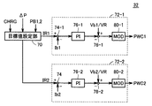
図5は、図1に示したMG−ECU32の充電制御に関する部分の機能ブロック図である。図5を参照して、MG−ECU32は、目標値設定部70と、第1制御部72−1と、第2制御部72−2とを含む。
FIG. 5 is a functional block diagram of a portion related to charge control of MG-
目標値設定部70は、充電指令CHRGを受け、かつ、電池ECU30から電力指令値ΔPを受けると、その受けた電力指令値ΔPを電圧Vb1で除算して目標電流IR1を生成し、電力指令値ΔPを符号反転した値を電圧Vb2で除算して目標電流IR2を生成する。
When target
また、目標値設定部70は、充電指令CHRGを受け、かつ、電池ECU30から充電電力指令値PB1,PB2を受けると、充電電力指令値PB1を電圧Vb1で除算して目標電流IR1を生成し、充電電力指令値PB2を電圧Vb2で除算して目標電流IR2を生成する。
Further, when the target
第1制御部72−1は、減算部74−1,78−1と、PI制御部76−1と、変調部80−1とを含む。減算部74−1は、目標値設定部70から出力される目標電流IR1から電流Ib1を減算し、その演算結果をPI制御部76−1へ出力する。PI制御部76−1は、目標電流IR1と電流Ib1との偏差を入力として比例積分演算を行ない、その演算結果を減算部78−1へ出力する。
First control unit 72-1 includes subtraction units 74-1 and 78-1, PI control unit 76-1, and modulation unit 80-1. Subtraction unit 74-1 subtracts current Ib1 from target current IR1 output from target
演算部78−1は、電圧Vb1/電圧VR(電圧Vhの目標電圧)で示されるコンバータ8−1の理論昇圧比の逆数からPI制御部76−1の出力を減算し、その演算結果をデューティー指令Ton1として変調部80−1へ出力する。変調部80−1は、デューティー指令Ton1と図示されない発振部により生成される搬送波(キャリア波)とに基づいて駆動信号PWC1を生成し、その生成した駆動信号PWC1をコンバータ8−1へ出力する。 Arithmetic unit 78-1 subtracts the output of PI control unit 76-1 from the inverse of the theoretical boost ratio of converter 8-1 indicated by voltage Vb1 / voltage VR (target voltage of voltage Vh), and calculates the result as a duty. The command Ton1 is output to the modulation unit 80-1. Modulation unit 80-1 generates drive signal PWC1 based on duty command Ton1 and a carrier wave (carrier wave) generated by an oscillation unit (not shown), and outputs the generated drive signal PWC1 to converter 8-1.
第2制御部72−2は、減算部74−2,78−2と、PI制御部76−2と、変調部80−2とを含む。減算部74−2は、目標値設定部70から出力される目標電流IR2から電流Ib2を減算し、その演算結果をPI制御部76−2へ出力する。PI制御部76−2は、目標電流IR2と電流Ib2との偏差を入力として比例積分演算を行ない、その演算結果を減算部78−2へ出力する。
Second control unit 72-2 includes subtraction units 74-2 and 78-2, PI control unit 76-2, and modulation unit 80-2. Subtraction unit 74-2 subtracts current Ib2 from target current IR2 output from target
演算部78−2は、電圧Vb2/電圧VRで示されるコンバータ8−2の理論昇圧比の逆数からPI制御部76−2の出力を減算し、その演算結果をデューティー指令Ton2として変調部80−2へ出力する。変調部80−2は、デューティー指令Ton2と図示されない発振部により生成される搬送波(キャリア波)とに基づいて駆動信号PWC2を生成し、その生成した駆動信号PWC2をコンバータ8−2へ出力する。 The calculation unit 78-2 subtracts the output of the PI control unit 76-2 from the reciprocal of the theoretical boost ratio of the converter 8-2 indicated by the voltage Vb2 / voltage VR, and uses the calculation result as the duty command Ton2 for the modulation unit 80- Output to 2. Modulation unit 80-2 generates drive signal PWC2 based on duty command Ton2 and a carrier wave (carrier wave) generated by an oscillation unit (not shown), and outputs the generated drive signal PWC2 to converter 8-2.
以上のように、この実施の形態1においては、外部電源34から蓄電装置6−1,6−2の充電が要求されると、充電に先立ち蓄電装置6−1,6−2間で充放電を行なうようにコンバータ8−1,8−2が制御される。そして、そのときに収集される各蓄電装置の電圧および電流に基づいて各蓄電装置の電圧電流特性が算出される。このとき、車両の走行状況による制約を受けることなく各蓄電装置で分極を解消可能な充放電が可能であり(充放電量大)、また、走行時に比べて周囲環境も安定しているので、電圧電流特性を正確に算出することができる。そして、この正確に算出された電圧電流特性に基づいて各蓄電装置のOCVが算出され、その算出されたOCVに基づいて各蓄電装置のSOCが推定される。したがって、この実施の形態1によれば、各蓄電装置のSOCを高精度に推定することができる。
As described above, in
また、この実施の形態1によれば、電流電圧特性およびOCVを算出しSOCを推定するための各蓄電装置の充放電は蓄電装置6−1,6−2間で行なわれるので、コンバータ8−1,8−2における電力損失は発生するものの、電力が無駄に捨てられたり消費されることはない。また、蓄電装置6−1,6−2間での充放電時に電力損失が発生しても、その後の外部電源34からの充電により損失分を補充することが可能である。
According to the first embodiment, charging / discharging of each power storage device for calculating current-voltage characteristics and OCV and estimating SOC is performed between power storage devices 6-1 and 6-2, so that converter 8- Although power loss occurs at 1 and 8-2, power is not wasted and consumed. Even if power loss occurs during charging / discharging between power storage devices 6-1 and 6-2, it is possible to supplement the loss by subsequent charging from
[実施の形態2]
実施の形態2では、蓄電装置6−1,6−2間での充放電時に算出される電圧電流特性に基づいて、各蓄電装置の劣化判定がさらに実施される。
[Embodiment 2]
In the second embodiment, deterioration determination of each power storage device is further performed based on the voltage-current characteristics calculated at the time of charging / discharging between power storage devices 6-1 and 6-2.
実施の形態2による電動車両の全体構成は、図1に示した実施の形態1による電動車両100と同じである。
The overall configuration of the electric vehicle according to the second embodiment is the same as that of
図6は、実施の形態2における電池ECU30Aの機能ブロック図である。図6を参照して、電池ECU30Aは、図2に示した実施の形態1における電池ECU30の構成において劣化判定部62をさらに含む。
FIG. 6 is a functional block diagram of
劣化判定部62は、蓄電装置6−1,6−2間での充放電時にV−I特性算出部50により算出された蓄電装置6−1,6−2の電圧電流特性を用いて、蓄電装置6−1,6−2の劣化状態をそれぞれ判定する。具体的には、劣化判定部62は、V−I特性算出部50により算出された電流電圧特性に基づいて、電流変化に対する電圧変化の依存性すなわち蓄電装置の内部抵抗を算出し、その算出結果に基づいて各蓄電装置の劣化状態を判定する。
The
図7は、蓄電装置の電圧電流特性を示した図である。図7を参照して、線k1(k2)は、同一の蓄電装置の電圧電流特性を示し、上述したように電流が零のときの電圧はOCVを示す。線k1(k2)の傾きは、電流変化に対する電圧変化の大きさすなわち蓄電装置の内部抵抗を示す。 FIG. 7 is a diagram illustrating voltage-current characteristics of the power storage device. Referring to FIG. 7, line k1 (k2) indicates the voltage-current characteristics of the same power storage device, and the voltage when the current is zero as described above indicates OCV. The slope of the line k1 (k2) indicates the magnitude of the voltage change with respect to the current change, that is, the internal resistance of the power storage device.
線k2で示される電流電圧特性は、線k1で示される電流電圧特性よりも傾きが大きい。すなわち、線k2で示される電流電圧特性を有する蓄電装置は、線k1で示される電流電圧特性を有する蓄電装置よりも内部抵抗が大きく、劣化が進行しているといえる。 The current-voltage characteristic indicated by the line k2 has a larger slope than the current-voltage characteristic indicated by the line k1. That is, it can be said that the power storage device having the current-voltage characteristic indicated by the line k2 has a larger internal resistance than the power storage device having the current-voltage characteristic indicated by the line k1, and the deterioration is progressing.
そこで、この実施の形態2では、V−I特性算出部50により算出された各蓄電装置の電圧電流特性において電流変化に対する電圧変化の依存性(傾き)を算出することにより、各蓄電装置の劣化状態を判定することとしたものである。そして、この実施の形態2では、蓄電装置6−1,6−2間での充放電時に算出される正確な電流電圧特性に基づいて劣化判定が行なわれるので、劣化判定精度も高い。
Therefore, in the second embodiment, the dependence (gradient) of the voltage change with respect to the current change is calculated in the voltage-current characteristic of each power storage device calculated by the VI
図8は、実施の形態2における電池ECU30Aによる蓄電装置6−1,6−2のSOC推定方法を示すフローチャートである。図8を参照して、このフローチャートは、図4に示したフローチャートにおいて、ステップS55,S57,S125をさらに含む。
FIG. 8 is a flowchart showing an SOC estimation method for power storage devices 6-1 and 6-2 by
すなわち、ステップS50において各蓄電装置のSOCが推定されると、電池ECU30Aは、ステップS30において算出された各蓄電装置の電圧電流特性に基づいて各蓄電装置の劣化判定を行なう(ステップS55)。具体的には、電池ECU30Aは、各蓄電装置の電圧電流特性の傾きを算出し、その算出された傾きを予め設定されたしきい値と比較することによって劣化判定を行なう。
That is, when the SOC of each power storage device is estimated in step S50,
そして、ステップS55において、蓄電装置6−1,6−2の少なくとも一方において電圧電流特性の傾きがしきい値よりも大きく、劣化が進行しているものと判定されると(ステップS55においてNG)、電池ECU30Aは、利用者に対して警告を出力する(ステップS57)。一方、ステップS55において、各蓄電装置の電流電圧特性の傾きがしきい値以下であり、劣化は進行していないものと判定されると(ステップS55においてOK)、電池ECU30Aは、ステップS60へ処理を移行する。
In step S55, when it is determined that the slope of the voltage-current characteristic is larger than the threshold value in at least one of power storage devices 6-1 and 6-2, and deterioration is progressing (NG in step S55). The
また、ステップS120において各蓄電装置のSOCが推定されると、電池ECU30Aは、ステップS100において算出された各蓄電装置の電圧電流特性に基づいて各蓄電装置の劣化判定を行なう(ステップS125)。
When the SOC of each power storage device is estimated in step S120,
そして、ステップS125において蓄電装置6−1,6−2の少なくとも一方が劣化しているものと判定されると(ステップS125においてNG)、電池ECU30Aは、ステップS57へ処理を移行する。一方、ステップS125において蓄電装置6−1,6−2のいずれも劣化していないものと判定されると(ステップS125においてOK)、電池ECU30Aは、ステップS130へ処理を移行する。
If it is determined in step S125 that at least one of power storage devices 6-1 and 6-2 has deteriorated (NG in step S125),
以上のように、この実施の形態2によれば、各蓄電装置のSOCを高精度に推定可能であるとともに、各蓄電装置の劣化状態も高精度に判定することができる。 As described above, according to the second embodiment, the SOC of each power storage device can be estimated with high accuracy, and the deterioration state of each power storage device can be determined with high accuracy.
なお、上記の各実施の形態においては、外部電源34から蓄電装置6−1,6−2の充電時、充電専用に設けられた充電用コンバータ26を用いて外部電源34からの電力を主正母線MPLおよび主負母線MNLに取り込むものとしたが、充電用コンバータを別途設けることなく、インバータ20−1,20−2を用いて外部電源34からの電力を入力するようにしてもよい。
In each of the above-described embodiments, when charging power storage devices 6-1 and 6-2 from
図9は、インバータ20−1,20−2を用いて外部電源34からの電力を入力可能な電動車両の全体ブロック図である。図9を参照して、この電動車両100Aは、図1に示した電動車両100の構成において、充電用コンバータ26を備えず、電力線ACL1,ACL2をさらに備える。
FIG. 9 is an overall block diagram of an electric vehicle capable of inputting electric power from the
電力線ACL1の一端は、モータジェネレータMG1の中性点N1に接続され、その他端は、受電部28に接続される。電力線ACL2の一端は、モータジェネレータMG2の中性点N2に接続され、その他端は、受電部28に接続される。
One end of
そして、インバータ20−1,20−2は、外部電源34から蓄電装置6−1,6−2の充電が行なわれるとき、後述の方法により、電力線ACL1,ACL2を介してモータジェネレータMG1,MG2の中性点N1,N2に与えられる外部電源34からの交流電力を直流電力に変換して主正母線MPLおよび主負母線MNLへ出力する。
When the power storage devices 6-1 and 6-2 are charged from the
図10は、図9に示したインバータ20−1,20−2およびモータジェネレータMG1,MG2の零相等価回路を示した図である。図10を参照して、各インバータ20−1,20−2は、三相ブリッジ回路から成り、各インバータ20−1,20−2においては、6個のスイッチング素子のオン/オフの組合わせは8パターン存在する。その8つのスイッチングパターンのうち2つは相間電圧が零となり、そのような電圧状態は零電圧ベクトルと称される。零電圧ベクトルについては、上アームの3つのスイッチング素子は互いに同じスイッチング状態(全てオンまたはオフ)とみなすことができ、また、下アームの3つのスイッチング素子も互いに同じスイッチング状態とみなすことができる。したがって、この図10では、インバータ20−1の上アームの3つのスイッチング素子は上アーム20−1Aとしてまとめて示され、インバータ20−1の下アームの3つのスイッチング素子は下アーム20−1Bとしてまとめて示されている。同様に、インバータ20−2の上アームの3つのスイッチング素子は上アーム20−2Aとしてまとめて示され、インバータ20−2の下アームの3つのスイッチング素子は下アーム20−2Bとしてまとめて示されている。 FIG. 10 shows a zero-phase equivalent circuit of inverters 20-1, 20-2 and motor generators MG1, MG2 shown in FIG. Referring to FIG. 10, each inverter 20-1 and 20-2 is composed of a three-phase bridge circuit. In each inverter 20-1 and 20-2, the on / off combination of six switching elements is There are 8 patterns. Two of the eight switching patterns have zero interphase voltage, and such a voltage state is called a zero voltage vector. For the zero voltage vector, the three switching elements of the upper arm can be regarded as the same switching state (all on or off), and the three switching elements of the lower arm can also be regarded as the same switching state. Therefore, in FIG. 10, the three switching elements of the upper arm of the inverter 20-1 are collectively shown as the upper arm 20-1A, and the three switching elements of the lower arm of the inverter 20-1 are shown as the lower arm 20-1B. It is shown together. Similarly, the three switching elements of the upper arm of the inverter 20-2 are collectively shown as an upper arm 20-2A, and the three switching elements of the lower arm of the inverter 20-2 are collectively shown as a lower arm 20-2B. ing.
図10に示されるように、この零相等価回路は、電力線ACL1,ACL2を介して中性点N1,N2に与えられる単相交流電力を入力とする単相PWMコンバータとみることができる。そこで、インバータ20−1,20−2の各々において零電圧ベクトルを変化させ、インバータ20−1,20−2を単相PWMコンバータのアームとして動作するようにスイッチング制御することによって、電力線ACL1,ACL2から入力される外部電源34からの交流電力を直流電力に変換して主正母線MPLおよび主負母線MNLへ出力することができる。
As shown in FIG. 10, this zero-phase equivalent circuit can be regarded as a single-phase PWM converter that receives single-phase AC power applied to neutral points N1 and N2 via power lines ACL1 and ACL2. Therefore, by changing the zero voltage vector in each of inverters 20-1 and 20-2 and performing switching control so that inverters 20-1 and 20-2 operate as an arm of a single-phase PWM converter, power lines ACL1 and ACL2 The AC power from the
なお、上記の各実施の形態においては、電動車両100(100A)は、2つの蓄電装置6−1,6−2およびそれぞれに対応するコンバータ8−1,8−2を含むものとしたが、さらに多くの蓄電装置およびそれに対応するコンバータを備えてもよい。その場合、外部電源34からの充電実行前にその複数の蓄電装置間で充放電を行なうことによって、上述の手法により各蓄電装置のSOCを高精度に推定することができる。
In each of the above-described embodiments, electric vehicle 100 (100A) includes two power storage devices 6-1 and 6-2 and converters 8-1 and 8-2 corresponding to the power storage devices 6-1 and 6-2, respectively. Further, more power storage devices and corresponding converters may be provided. In that case, the SOC of each power storage device can be estimated with high accuracy by the above-described method by performing charging / discharging among the plurality of power storage devices before executing charging from the
また、上記の各実施の形態において、電動車両100(100A)は、燃料を用いて運動エネルギーを発生する内燃機関をさらに搭載したハイブリッド車両や、内燃機関を搭載しない電気自動車、燃料を用いて電気エネルギーを発生する燃料電池(Fuel Cell)をさらに搭載した燃料電池車であってもよい。 In each of the above-described embodiments, the electric vehicle 100 (100A) is an electric vehicle using a hybrid vehicle that further includes an internal combustion engine that generates kinetic energy using fuel, an electric vehicle that does not include the internal combustion engine, and fuel. It may be a fuel cell vehicle further equipped with a fuel cell that generates energy.
なお、上記において、電池ECU30,30Aにおける制御は、実際には、CPU(Central Processing Unit)によって行なわれ、CPUは、図4,図8に示したフローチャートの各ステップを備えるプログラムをROM(Read Only Memory)から読出し、その読出したプログラムを実行して図4,図8に示したフローチャートに従って処理を実行する。したがって、ROMは、図4,図8に示したフローチャートの各ステップを備えるプログラムを記録したコンピュータ(CPU)読取可能な記録媒体に相当する。
In the above, the control in the
なお、上記において、蓄電装置6−1,6−2のいずれか一方は、この発明における「第1の蓄電装置」に対応する。そして、蓄電装置6−1が「第1の蓄電装置」に対応するとき、コンバータ8−1,8−2および蓄電装置6−2は、この発明における「電力装置」を形成し、蓄電装置6−2が「第1の蓄電装置」に対応するとき、コンバータ8−1,8−2および蓄電装置6−1は、この発明における「電力装置」を形成する。 In the above, any one of power storage devices 6-1 and 6-2 corresponds to the “first power storage device” in the present invention. When power storage device 6-1 corresponds to “first power storage device”, converters 8-1, 8-2 and power storage device 6-2 form “power device” in the present invention, and power storage device 6 −2 corresponds to “first power storage device”, converters 8-1, 8-2 and power storage device 6-1 form “power device” in the present invention.
また、充電用コンバータ26は、この発明における「充電装置」に対応し、電動車両100Aにおけるインバータ20−1,20−2、モータジェネレータMG1,MG2および電力線ACL1,ACL2も、この発明における「充電装置」を形成する。さらに、電池ECU30,30AおよびMG−ECU32は、この発明における「制御装置」を形成し、V−I特性算出部50は、この発明における「第1の演算部」に対応する。また、さらに、OCV算出部52は、この発明における「第2の演算部」に対応し、初期SOC推定部54は、この発明における「充電状態推定部」に対応する。
Charging
また、さらに、蓄電装置6−1が「第1の蓄電装置」に対応するとき、蓄電装置6−2は、この発明における「少なくとも1つの第2の蓄電装置」に対応し、蓄電装置6−2が「第1の蓄電装置」に対応するとき、蓄電装置6−1は、この発明における「少なくとも1つの第2の蓄電装置」に対応する。また、さらに、コンバータ8−1,8−2は、この発明における「複数の電圧変換装置」に対応する。 Furthermore, when power storage device 6-1 corresponds to “first power storage device”, power storage device 6-2 corresponds to “at least one second power storage device” in the present invention, and power storage device 6— When 2 corresponds to “first power storage device”, power storage device 6-1 corresponds to “at least one second power storage device” in the present invention. Furthermore, converters 8-1 and 8-2 correspond to “a plurality of voltage conversion devices” in the present invention.
今回開示された実施の形態は、すべての点で例示であって制限的なものではないと考えられるべきである。本発明の範囲は、上記した実施の形態の説明ではなくて特許請求の範囲によって示され、特許請求の範囲と均等の意味および範囲内でのすべての変更が含まれることが意図される。 The embodiment disclosed this time should be considered as illustrative in all points and not restrictive. The scope of the present invention is shown not by the above description of the embodiments but by the scope of claims for patent, and is intended to include meanings equivalent to the scope of claims for patent and all modifications within the scope.
6−1,6−2 蓄電装置、8−1,8−2 コンバータ、10−1,10−2 電流センサ、12−1,12−2,18 電圧センサ、20−1,20−2 インバータ、22 動力伝達機構、24 駆動軸、26 充電用コンバータ、28 受電部、30,30A 電池ECU、32 MG−ECU、34 外部電源、50 V−I特性算出部、52 OCV算出部、54 初期SOC推定部、56 充放電制御部、58 SOC演算部、60 充電制御部、62 劣化判定部、70 目標値設定部、72−1 第1制御部、72−2 第2制御部、74−1,74−2,78−1,78−2 減算部、76−1,76−2 PI制御部、80−1,80−2 変調部、100,100A 電動車両、PL1,PL2 正極線、NL1,NL2 負極線、C コンデンサ、MPL 主正母線、MNL 主負母線、MG1,MG2 モータジェネレータ、ACL1,ACL2 電力線。 6-1, 6-2 power storage device, 8-1, 8-2 converter, 10-1, 10-2 current sensor, 12-1, 12-2, 18 voltage sensor, 20-1, 20-2 inverter, 22 power transmission mechanism, 24 drive shaft, 26 charging converter, 28 power receiving unit, 30, 30A battery ECU, 32 MG-ECU, 34 external power supply, 50 VI characteristic calculation unit, 52 OCV calculation unit, 54 initial SOC estimation Unit, 56 charge / discharge control unit, 58 SOC calculation unit, 60 charge control unit, 62 deterioration determination unit, 70 target value setting unit, 72-1 first control unit, 72-2 second control unit, 74-1, 74 -2, 78-1, 78-2 Subtraction unit, 76-1, 76-2 PI control unit, 80-1, 80-2 modulation unit, 100, 100A electric vehicle, PL1, PL2 positive line, NL1, NL2 negative electrode Line, C Capacitor, MPL main positive bus, MNL main negative bus, MG1, MG2 motor generator, ACL1, ACL2 power line.
Claims (11)
車両外部の電源から前記第1の蓄電装置を充電可能なように構成された充電装置と、
前記第1の蓄電装置と電力を授受可能なように構成された電力装置と、
前記電力装置を制御する制御装置とを備え、
前記制御装置は、
前記充電装置による前記第1の蓄電装置の充電が要求されると、前記第1の蓄電装置と前記電力装置との間で電力を授受するように前記電力装置を制御する充放電制御部と、
前記第1の蓄電装置と前記電力装置との間で電力が授受されているときの前記第1の蓄電装置の電圧および電流に基づいて、前記電圧と前記電流との相関関係を示す電圧電流特性を算出する第1の演算部と、
前記第1の演算部により算出された電圧電流特性に基づいて前記第1の蓄電装置の開放端電圧を算出する第2の演算部と、
予め設定された前記第1の蓄電装置の開放端電圧と充電状態との相関関係を用いて、前記第2の演算部により算出された開放端電圧に基づいて前記第1の蓄電装置の充電状態を推定する充電状態推定部とを含む、電動車両。 A first power storage device capable of charging and discharging;
A charging device configured to be able to charge the first power storage device from a power source external to the vehicle;
A power device configured to be able to exchange power with the first power storage device;
A control device for controlling the power device,
The controller is
When charging of the first power storage device by the charging device is requested, a charge / discharge control unit that controls the power device to transfer power between the first power storage device and the power device;
Voltage-current characteristics indicating a correlation between the voltage and the current based on the voltage and current of the first power storage device when power is being transferred between the first power storage device and the power device A first arithmetic unit for calculating
A second arithmetic unit that calculates an open-end voltage of the first power storage device based on the voltage-current characteristic calculated by the first arithmetic unit;
The state of charge of the first power storage device based on the open end voltage calculated by the second computing unit using a correlation between the preset open end voltage of the first power storage device and the state of charge. An electric vehicle including a charge state estimation unit that estimates
前記第1の演算部は、前記第1の蓄電装置および前記少なくとも1つの第2の蓄電装置間で電力が授受されているときの前記少なくとも1つの第2の蓄電装置の電圧および電流に基づいて、前記少なくとも1つの第2の蓄電装置についての電圧と電流との相関関係を示す電圧電流特性をさらに算出し、
前記第2の演算部は、前記第1の演算部により算出された前記少なくとも1つの第2の蓄電装置の電圧電流特性に基づいて前記少なくとも1つの第2の蓄電装置の開放端電圧をさらに算出し、
前記充電状態推定部は、予め設定された前記少なくとも1つの第2の蓄電装置の開放端電圧と充電状態との相関関係を用いて、前記第2の演算部により算出された前記少なくとも1つの第2の蓄電装置の開放端電圧に基づいて前記少なくとも1つの第2の蓄電装置の充電状態をさらに推定する、請求項1または請求項2に記載の電動車両。 The power device includes at least one second power storage device capable of being charged and discharged,
The first arithmetic unit is based on the voltage and current of the at least one second power storage device when power is transferred between the first power storage device and the at least one second power storage device. , Further calculating a voltage-current characteristic indicating a correlation between voltage and current for the at least one second power storage device;
The second calculation unit further calculates an open-circuit voltage of the at least one second power storage device based on a voltage-current characteristic of the at least one second power storage device calculated by the first calculation unit. And
The charge state estimation unit uses the correlation between the preset open-circuit voltage of the at least one second power storage device and the charge state, and the at least one first calculation unit calculated by the second calculation unit. 3. The electric vehicle according to claim 1, wherein a charge state of the at least one second power storage device is further estimated based on an open end voltage of the second power storage device.
前記充放電制御部は、前記第1の蓄電装置および前記少なくとも1つの第2の蓄電装置間で電力を授受するように前記複数の電圧変換装置を制御する、請求項3に記載の電動車両。 The power device further includes a plurality of voltage conversion devices provided corresponding to the first power storage device and the at least one second power storage device,
The electric vehicle according to claim 3, wherein the charge / discharge control unit controls the plurality of voltage conversion devices so as to transfer power between the first power storage device and the at least one second power storage device.
前記電動車両は、
充放電可能な第1の蓄電装置と、
車両外部の電源から前記第1の蓄電装置を充電可能なように構成された充電装置と、
前記第1の蓄電装置と電力を授受可能なように構成された電力装置とを備え、
前記充電状態推定方法は、
前記充電装置による前記第1の蓄電装置の充電が要求されると、前記第1の蓄電装置と前記電力装置との間で電力を授受するように前記電力装置を制御する第1のステップと、
前記第1の蓄電装置と前記電力装置との間で電力が授受されているときの前記第1の蓄電装置の電圧および電流に基づいて、前記電圧と前記電流との相関関係を示す電圧電流特性を算出する第2のステップと、
その算出された電圧電流特性に基づいて前記第1の蓄電装置の開放端電圧を算出する第3のステップと、
予め設定された前記第1の蓄電装置の開放端電圧と充電状態との相関関係を用いて、前記第3のステップにおいて算出された開放端電圧に基づいて前記第1の蓄電装置の充電状態を推定する第4のステップとを含む、充電状態推定方法。 A charging state estimation method for estimating a charging state of a power storage device mounted on an electric vehicle,
The electric vehicle is
A first power storage device capable of charging and discharging;
A charging device configured to be able to charge the first power storage device from a power source external to the vehicle;
A power device configured to be able to exchange power with the first power storage device,
The charging state estimation method includes:
When charging of the first power storage device by the charging device is requested, the first step of controlling the power device to transfer power between the first power storage device and the power device;
A voltage-current characteristic indicating a correlation between the voltage and the current based on the voltage and current of the first power storage device when power is transferred between the first power storage device and the power device. A second step of calculating
A third step of calculating an open end voltage of the first power storage device based on the calculated voltage-current characteristic;
The charge state of the first power storage device is determined based on the open end voltage calculated in the third step, using a correlation between the open-end voltage and the charge state of the first power storage device set in advance. A charging state estimation method including a fourth step of estimation.
前記第2のステップにおいて、前記第1の蓄電装置および前記少なくとも1つの第2の蓄電装置間で電力が授受されているときの前記少なくとも1つの第2の蓄電装置の電圧および電流に基づいて、前記少なくとも1つの第2の蓄電装置についての電圧と電流との相関関係を示す電圧電流特性がさらに算出され、
前記第3のステップにおいて、前記第2のステップにおいて算出された前記少なくとも1つの第2の蓄電装置の電圧電流特性に基づいて前記少なくとも1つの第2の蓄電装置の開放端電圧がさらに算出され、
前記第4のステップにおいて、予め設定された前記少なくとも1つの第2の蓄電装置の開放端電圧と充電状態との相関関係を用いて、前記第3のステップにおいて算出された前記少なくとも1つの第2の蓄電装置の開放端電圧に基づいて前記少なくとも1つの第2の蓄電装置の充電状態がさらに推定される、請求項6または請求項7に記載の充電状態推定方法。 The power device includes at least one second power storage device capable of being charged and discharged,
In the second step, based on the voltage and current of the at least one second power storage device when power is transferred between the first power storage device and the at least one second power storage device, A voltage-current characteristic indicating a correlation between voltage and current for the at least one second power storage device is further calculated,
In the third step, an open circuit voltage of the at least one second power storage device is further calculated based on a voltage-current characteristic of the at least one second power storage device calculated in the second step,
In the fourth step, the at least one second calculated in the third step using a correlation between a preset open-circuit voltage of the at least one second power storage device and a charged state. The charging state estimation method according to claim 6 or 7, wherein a charging state of the at least one second power storage device is further estimated based on an open-circuit voltage of the power storage device.
前記第1のステップにおいて、前記第1の蓄電装置および前記少なくとも1つの第2の蓄電装置間で電力を授受するように前記複数の電圧変換装置が制御される、請求項8に記載の充電状態推定方法。 The power device further includes a plurality of voltage conversion devices provided corresponding to the first power storage device and the at least one second power storage device,
The state of charge according to claim 8, wherein, in the first step, the plurality of voltage conversion devices are controlled so as to transfer power between the first power storage device and the at least one second power storage device. Estimation method.
Priority Applications (9)
| Application Number | Priority Date | Filing Date | Title |
|---|---|---|---|
| JP2007055795A JP4706648B2 (en) | 2007-03-06 | 2007-03-06 | Electric vehicle, charging state estimation method, and computer-readable recording medium recording a program for causing a computer to execute the charging state estimation method |
| RU2009136696/07A RU2416142C1 (en) | 2007-03-06 | 2008-02-29 | Transport vehicle with electric drive, evaluation method of charge condition and machine-processable data storage medium with stored programme to implement evaluation method of charge condition |
| BRPI0808425-4A BRPI0808425B1 (en) | 2007-03-06 | 2008-02-29 | VEHICLE MOVED TO ELECTRICITY AND METHOD FOR EVALUATING CHARGE STATE. |
| CN2008800070079A CN101627517B (en) | 2007-03-06 | 2008-02-29 | Electric vehicle, method for estimating state of charge, and computer readable recording medium recording program for executing state of charge estimation method on computer |
| US12/449,035 US8648571B2 (en) | 2007-03-06 | 2008-02-29 | Electric-powered vehicle, method for estimating state of charge, and computer-readable storage medium having program stored therein for causing computer to execute method for estimating state of charge |
| PCT/JP2008/054111 WO2008108455A1 (en) | 2007-03-06 | 2008-02-29 | Electric vehicle, method for estimating state of charge, and computer readable recording medium recording program for executing state of charge estimation method on computer |
| EP08721529.9A EP2120309B1 (en) | 2007-03-06 | 2008-02-29 | Electric vehicle, method for estimating state of charge, and computer readable recording medium recording program for executing state of charge estimation method on computer |
| ES08721529T ES2746476T3 (en) | 2007-03-06 | 2008-02-29 | Electric vehicle, method of estimating the state of charge and computer-readable recording medium recording program for executing the method of estimating the state of charge on a computer |
| KR1020097020742A KR101087632B1 (en) | 2007-03-06 | 2008-02-29 | Electric vehicle, method for estimating state of charge, and computer readable recording medium recording program for executing state of charge estimation method on computer |
Applications Claiming Priority (1)
| Application Number | Priority Date | Filing Date | Title |
|---|---|---|---|
| JP2007055795A JP4706648B2 (en) | 2007-03-06 | 2007-03-06 | Electric vehicle, charging state estimation method, and computer-readable recording medium recording a program for causing a computer to execute the charging state estimation method |
Publications (2)
| Publication Number | Publication Date |
|---|---|
| JP2008220080A JP2008220080A (en) | 2008-09-18 |
| JP4706648B2 true JP4706648B2 (en) | 2011-06-22 |
Family
ID=39738320
Family Applications (1)
| Application Number | Title | Priority Date | Filing Date |
|---|---|---|---|
| JP2007055795A Active JP4706648B2 (en) | 2007-03-06 | 2007-03-06 | Electric vehicle, charging state estimation method, and computer-readable recording medium recording a program for causing a computer to execute the charging state estimation method |
Country Status (9)
| Country | Link |
|---|---|
| US (1) | US8648571B2 (en) |
| EP (1) | EP2120309B1 (en) |
| JP (1) | JP4706648B2 (en) |
| KR (1) | KR101087632B1 (en) |
| CN (1) | CN101627517B (en) |
| BR (1) | BRPI0808425B1 (en) |
| ES (1) | ES2746476T3 (en) |
| RU (1) | RU2416142C1 (en) |
| WO (1) | WO2008108455A1 (en) |
Families Citing this family (38)
| Publication number | Priority date | Publication date | Assignee | Title |
|---|---|---|---|---|
| JP4893653B2 (en) * | 2008-02-19 | 2012-03-07 | トヨタ自動車株式会社 | Vehicle, rechargeable battery state of charge estimation method and vehicle control method |
| JP5187152B2 (en) * | 2008-11-17 | 2013-04-24 | トヨタ自動車株式会社 | Vehicle power supply system and vehicle |
| EP2413420B1 (en) * | 2009-03-27 | 2018-11-21 | Hitachi, Ltd. | Electric storage device |
| JP4978662B2 (en) | 2009-06-24 | 2012-07-18 | トヨタ自動車株式会社 | CHARGE STATE ESTIMATION DEVICE AND CHARGE STATE ESTIMATION METHOD |
| JP5394563B2 (en) * | 2010-02-25 | 2014-01-22 | 三洋電機株式会社 | Battery control device, battery system, electric vehicle, charge control device, charger, moving object, power supply system, power storage device, and power supply device |
| US8820444B2 (en) * | 2010-04-16 | 2014-09-02 | Tuan Nguyen | Electric vehicle having exchangeable battery modules and method of resupply therefor |
| BR112012027318A2 (en) * | 2010-06-07 | 2016-08-02 | Mitsubishi Electric Corp | charge state estimation apparatus |
| US9726732B2 (en) * | 2010-06-22 | 2017-08-08 | GM Global Technology Operations LLC | Adaptive battery parameter extraction and SOC estimation for lithium-ion battery |
| US9354277B2 (en) * | 2010-10-29 | 2016-05-31 | Gm Global Technology Operatins Llc | Apparatus of SOC estimation during plug-in charge mode |
| KR101238478B1 (en) * | 2011-01-16 | 2013-03-04 | 김득수 | The Measurment Method of Battery SOC |
| JP5747610B2 (en) * | 2011-03-30 | 2015-07-15 | ソニー株式会社 | CHARGE CONTROL DEVICE, CHARGE CONTROL METHOD, PROGRAM, AND SYSTEM |
| JP5794525B2 (en) * | 2011-07-22 | 2015-10-14 | 東洋電産株式会社 | Battery charger for electric vehicles and rescue vehicle |
| JP5870590B2 (en) * | 2011-09-29 | 2016-03-01 | ミツミ電機株式会社 | Battery state measuring method and battery state measuring apparatus |
| JP5857229B2 (en) * | 2011-09-30 | 2016-02-10 | パナソニックIpマネジメント株式会社 | Internal resistance detection circuit and battery power supply device |
| JP6065561B2 (en) * | 2012-03-08 | 2017-01-25 | 日産自動車株式会社 | Secondary battery control device and SOC detection method |
| FR2989779B1 (en) * | 2012-04-19 | 2015-02-06 | Commissariat Energie Atomique | DEVICE FOR DETERMINING A CHARACTERISTIC OF A BATTERY AND METHOD FOR OPERATING SUCH A DEVICE |
| KR101394867B1 (en) | 2012-09-28 | 2014-05-13 | 기아자동차주식회사 | Method for DTE computation of green car |
| US20140320085A1 (en) * | 2013-04-24 | 2014-10-30 | Dynapack International Technology Corporation | Charging device and control method thereof |
| US9205750B2 (en) | 2013-07-23 | 2015-12-08 | Ford Global Technologies, Llc | Method to estimate battery open-circuit voltage based on transient resistive effects |
| JP6260812B2 (en) * | 2013-12-05 | 2018-01-17 | パナソニックIpマネジメント株式会社 | Battery remaining capacity estimation device, battery remaining capacity determination method, and battery remaining capacity determination program |
| CN104714182A (en) * | 2013-12-11 | 2015-06-17 | 广州汽车集团股份有限公司 | Method and system for determining state-of-charge value of battery |
| GB201407805D0 (en) * | 2014-05-02 | 2014-06-18 | Dukosi Ltd | Battery condition determination |
| US20160001670A1 (en) * | 2014-07-01 | 2016-01-07 | Ford Global Technologies, Llc | System and method for battery management |
| JP6412847B2 (en) | 2015-10-27 | 2018-10-24 | 本田技研工業株式会社 | Power storage device and control method |
| JP6364396B2 (en) * | 2015-10-27 | 2018-07-25 | 本田技研工業株式会社 | Power storage device, transport device and control method |
| JP6220904B2 (en) | 2016-01-14 | 2017-10-25 | 本田技研工業株式会社 | Power storage device |
| JP6122164B1 (en) * | 2016-02-04 | 2017-04-26 | 本田技研工業株式会社 | Power storage device, transport device having the power storage device, determination method for determining correlation information between SOC and OCV of storage battery, and program for determining the correlation information |
| JP5948518B1 (en) * | 2016-02-04 | 2016-07-06 | 本田技研工業株式会社 | Power storage device, transport device having the power storage device, failure determination method, and failure determination program |
| JP5980458B1 (en) * | 2016-03-30 | 2016-08-31 | 本田技研工業株式会社 | Power supply apparatus, transport apparatus having the power supply apparatus, estimation method for estimating correlation information between charging rate of storage unit and open-circuit voltage, and program for estimating correlation information |
| JP5980459B1 (en) * | 2016-03-30 | 2016-08-31 | 本田技研工業株式会社 | Power supply apparatus, transport apparatus having the power supply apparatus, estimation method for estimating correlation information between charging rate of storage unit and open-circuit voltage, and program for estimating correlation information |
| JP5980457B1 (en) * | 2016-03-30 | 2016-08-31 | 本田技研工業株式会社 | Power supply apparatus, transport apparatus having the power supply apparatus, estimation method for estimating correlation information between charging rate of storage unit and open-circuit voltage, and program for estimating correlation information |
| CN107340476B (en) * | 2016-04-29 | 2021-01-26 | 株式会社日立制作所 | Battery electrical state monitoring system and electrical state monitoring method |
| JP6551362B2 (en) * | 2016-10-20 | 2019-07-31 | 株式会社デンソー | Power supply system |
| CN106427652B (en) * | 2016-11-23 | 2018-08-21 | 杭州衡源汽车科技有限公司 | The charging switching system and its control method of electric vehicle |
| CN107359379B (en) * | 2017-07-19 | 2019-11-26 | 华霆(合肥)动力技术有限公司 | Fast charge method and device |
| CN109606202B (en) * | 2019-01-07 | 2024-01-26 | 郑州轻工业学院 | Power battery control method and device |
| CN113634645B (en) * | 2021-08-27 | 2023-05-02 | 保隆(安徽)汽车配件有限公司 | Flanging die and flanging method for preventing product from deforming |
| DE102022209368A1 (en) * | 2022-09-08 | 2024-03-14 | Siemens Mobility GmbH | Method for determining a voltage characteristic of an electrical energy storage device |
Citations (4)
| Publication number | Priority date | Publication date | Assignee | Title |
|---|---|---|---|---|
| JP2000306613A (en) * | 1999-04-20 | 2000-11-02 | Nissan Motor Co Ltd | Battery state monitoring device |
| JP2003092805A (en) * | 2001-09-20 | 2003-03-28 | Sanyo Electric Co Ltd | Power supply unit for hybrid car |
| JP2003189411A (en) * | 2001-12-11 | 2003-07-04 | Araco Corp | Hybrid vehicle |
| JP2004031123A (en) * | 2002-06-26 | 2004-01-29 | Nissan Motor Co Ltd | Capacity calculation method and device for battery pack connected in parallel |
Family Cites Families (13)
| Publication number | Priority date | Publication date | Assignee | Title |
|---|---|---|---|---|
| JP3864590B2 (en) * | 1998-11-25 | 2007-01-10 | トヨタ自動車株式会社 | Battery charge state detection device |
| JP3543662B2 (en) | 1999-03-09 | 2004-07-14 | 日産自動車株式会社 | SOC calculation method for secondary battery for electric vehicle |
| JP2004354050A (en) | 2002-05-14 | 2004-12-16 | Yazaki Corp | Charging state estimation method and open circuit voltage estimation method of battery, and deterioration degree calculation device and method |
| JP4228760B2 (en) * | 2002-07-12 | 2009-02-25 | トヨタ自動車株式会社 | Battery charge state estimation device |
| JP3689084B2 (en) * | 2002-12-11 | 2005-08-31 | 三菱電機株式会社 | Battery charge state calculation device and battery charge state calculation method |
| EP1571457A4 (en) * | 2002-12-11 | 2010-04-21 | Gs Yuasa Corp | Battery charged condition computing device and battery charged condition computing method |
| JP2005147987A (en) * | 2003-11-19 | 2005-06-09 | Yazaki Corp | Method and device for inferring saturated polarization, and method for inferring dischargeable capacity |
| RU2282301C2 (en) * | 2004-10-11 | 2006-08-20 | Государственное образовательное учреждение высшего профессионального образования Самарский государственный технический университет | Energy plant with asynchronous starter-generator |
| JP4085334B2 (en) * | 2004-11-09 | 2008-05-14 | 株式会社デンソー | Dual power supply type vehicle power supply |
| CN100364203C (en) | 2005-01-21 | 2008-01-23 | 宇泉能源科技股份有限公司 | Portable composite battery managing system |
| JP4520959B2 (en) | 2005-04-22 | 2010-08-11 | アイシン精機株式会社 | Power supply system |
| JP4839722B2 (en) * | 2005-08-08 | 2011-12-21 | トヨタ自動車株式会社 | Vehicle power supply |
| CA2523240C (en) * | 2005-10-11 | 2009-12-08 | Delaware Systems Inc. | Universal battery module and controller therefor |
-
2007
- 2007-03-06 JP JP2007055795A patent/JP4706648B2/en active Active
-
2008
- 2008-02-29 BR BRPI0808425-4A patent/BRPI0808425B1/en not_active IP Right Cessation
- 2008-02-29 US US12/449,035 patent/US8648571B2/en not_active Expired - Fee Related
- 2008-02-29 RU RU2009136696/07A patent/RU2416142C1/en not_active IP Right Cessation
- 2008-02-29 KR KR1020097020742A patent/KR101087632B1/en not_active IP Right Cessation
- 2008-02-29 ES ES08721529T patent/ES2746476T3/en active Active
- 2008-02-29 EP EP08721529.9A patent/EP2120309B1/en active Active
- 2008-02-29 WO PCT/JP2008/054111 patent/WO2008108455A1/en active Application Filing
- 2008-02-29 CN CN2008800070079A patent/CN101627517B/en not_active Expired - Fee Related
Patent Citations (4)
| Publication number | Priority date | Publication date | Assignee | Title |
|---|---|---|---|---|
| JP2000306613A (en) * | 1999-04-20 | 2000-11-02 | Nissan Motor Co Ltd | Battery state monitoring device |
| JP2003092805A (en) * | 2001-09-20 | 2003-03-28 | Sanyo Electric Co Ltd | Power supply unit for hybrid car |
| JP2003189411A (en) * | 2001-12-11 | 2003-07-04 | Araco Corp | Hybrid vehicle |
| JP2004031123A (en) * | 2002-06-26 | 2004-01-29 | Nissan Motor Co Ltd | Capacity calculation method and device for battery pack connected in parallel |
Also Published As
| Publication number | Publication date |
|---|---|
| US20100045239A1 (en) | 2010-02-25 |
| EP2120309A4 (en) | 2017-10-11 |
| EP2120309B1 (en) | 2019-08-21 |
| RU2416142C1 (en) | 2011-04-10 |
| BRPI0808425A2 (en) | 2014-07-22 |
| CN101627517B (en) | 2013-01-09 |
| EP2120309A1 (en) | 2009-11-18 |
| KR20090117835A (en) | 2009-11-12 |
| CN101627517A (en) | 2010-01-13 |
| BRPI0808425B1 (en) | 2019-04-24 |
| WO2008108455A1 (en) | 2008-09-12 |
| JP2008220080A (en) | 2008-09-18 |
| US8648571B2 (en) | 2014-02-11 |
| ES2746476T3 (en) | 2020-03-06 |
| KR101087632B1 (en) | 2011-11-30 |
Similar Documents
| Publication | Publication Date | Title |
|---|---|---|
| JP4706648B2 (en) | Electric vehicle, charging state estimation method, and computer-readable recording medium recording a program for causing a computer to execute the charging state estimation method | |
| JP4893653B2 (en) | Vehicle, rechargeable battery state of charge estimation method and vehicle control method | |
| US8340932B2 (en) | Vehicle power supply device and method of estimating state of charge of power storage device in vehicle power supply device | |
| US10011184B2 (en) | Power supply system for vehicle | |
| JP4525809B2 (en) | Power supply system, vehicle equipped with the same, and control method of power supply system | |
| JP4380772B2 (en) | POWER SUPPLY DEVICE, VEHICLE EQUIPPED WITH THE SAME, CONTROL METHOD FOR POWER SUPPLY DEVICE, AND COMPUTER-READABLE RECORDING MEDIUM CONTAINING PROGRAM FOR CAUSING COMPUTER TO EXECUTE THE CONTROL METHOD | |
| WO2008056818A1 (en) | Electric vehicle and method of controlling voltage conversion device | |
| JP5413507B2 (en) | VEHICLE CONTROL DEVICE AND VEHICLE CONTROL METHOD | |
| WO2012176275A1 (en) | Device for charging storage device and vehicle mounting same | |
| EP2472700A1 (en) | Charge control device for vehicle, and electric vehicle provided with same | |
| JP4569696B2 (en) | Electric vehicle and control method thereof | |
| JP4983639B2 (en) | POWER SUPPLY SYSTEM, VEHICLE HAVING THE SAME, AND OUTPUT LIMITATION CONTROL METHOD FOR POWER SUPPLY SYSTEM | |
| JP2010004667A (en) | Power supply system | |
| JP5958361B2 (en) | Vehicle power supply device and vehicle equipped with the same | |
| JP5803518B2 (en) | Vehicle and vehicle control method | |
| JP5299166B2 (en) | Power supply system, electric vehicle including the same, and control method of power supply system | |
| JP2023103904A (en) | power storage system |
Legal Events
| Date | Code | Title | Description |
|---|---|---|---|
| TRDD | Decision of grant or rejection written | ||
| A01 | Written decision to grant a patent or to grant a registration (utility model) |
Free format text: JAPANESE INTERMEDIATE CODE: A01 Effective date: 20110215 |
|
| A61 | First payment of annual fees (during grant procedure) |
Free format text: JAPANESE INTERMEDIATE CODE: A61 Effective date: 20110228 |
|
| R151 | Written notification of patent or utility model registration |
Ref document number: 4706648 Country of ref document: JP Free format text: JAPANESE INTERMEDIATE CODE: R151 |