JP4703642B2 - Apparatus and method - Google Patents

Apparatus and method Download PDF

Info

Publication number
JP4703642B2
JP4703642B2 JP2007509004A JP2007509004A JP4703642B2 JP 4703642 B2 JP4703642 B2 JP 4703642B2 JP 2007509004 A JP2007509004 A JP 2007509004A JP 2007509004 A JP2007509004 A JP 2007509004A JP 4703642 B2 JP4703642 B2 JP 4703642B2
Authority
JP
Japan
Prior art keywords
dose
transfer
arm
transfer means
path
Prior art date
Legal status (The legal status is an assumption and is not a legal conclusion. Google has not performed a legal analysis and makes no representation as to the accuracy of the status listed.)
Expired - Fee Related
Application number
JP2007509004A
Other languages
Japanese (ja)
Other versions
JP2007533507A (en
Inventor
パリネロ,フィオレンツォ
ズッファ,ゼノ
ボルガッティ,マウリツィオ
バルボニ,アレッサンドロ
カメラニ,マッテオ
バッティラーニ,マウロ
ベルトランディ,ダリオ
Original Assignee
サックミ コーペラティバ マッカニキ イモラ ソシエタ コーペラティバ
Priority date (The priority date is an assumption and is not a legal conclusion. Google has not performed a legal analysis and makes no representation as to the accuracy of the date listed.)
Filing date
Publication date
Priority claimed from ITRE20040041 external-priority patent/ITRE20040041A1/en
Priority claimed from ITRE20040042 external-priority patent/ITRE20040042A1/en
Priority claimed from ITRE20040039 external-priority patent/ITRE20040039A1/en
Priority claimed from IT000040A external-priority patent/ITRE20040040A1/en
Priority claimed from PCT/IB2005/001005 external-priority patent/WO2005102646A1/en
Application filed by サックミ コーペラティバ マッカニキ イモラ ソシエタ コーペラティバ filed Critical サックミ コーペラティバ マッカニキ イモラ ソシエタ コーペラティバ
Priority claimed from PCT/IB2005/001085 external-priority patent/WO2005102641A2/en
Publication of JP2007533507A publication Critical patent/JP2007533507A/en
Application granted granted Critical
Publication of JP4703642B2 publication Critical patent/JP4703642B2/en
Expired - Fee Related legal-status Critical Current
Anticipated expiration legal-status Critical

Links

Images

Classifications

    • BPERFORMING OPERATIONS; TRANSPORTING
    • B29WORKING OF PLASTICS; WORKING OF SUBSTANCES IN A PLASTIC STATE IN GENERAL
    • B29CSHAPING OR JOINING OF PLASTICS; SHAPING OF MATERIAL IN A PLASTIC STATE, NOT OTHERWISE PROVIDED FOR; AFTER-TREATMENT OF THE SHAPED PRODUCTS, e.g. REPAIRING
    • B29C31/00Handling, e.g. feeding of the material to be shaped, storage of plastics material before moulding; Automation, i.e. automated handling lines in plastics processing plants, e.g. using manipulators or robots
    • B29C31/04Feeding of the material to be moulded, e.g. into a mould cavity
    • B29C31/042Feeding of the material to be moulded, e.g. into a mould cavity using dispensing heads, e.g. extruders, placed over or apart from the moulds
    • B29C31/048Feeding of the material to be moulded, e.g. into a mould cavity using dispensing heads, e.g. extruders, placed over or apart from the moulds the material being severed at the dispensing head exit, e.g. as ring, drop or gob, and transported immediately into the mould, e.g. by gravity
    • BPERFORMING OPERATIONS; TRANSPORTING
    • B29WORKING OF PLASTICS; WORKING OF SUBSTANCES IN A PLASTIC STATE IN GENERAL
    • B29CSHAPING OR JOINING OF PLASTICS; SHAPING OF MATERIAL IN A PLASTIC STATE, NOT OTHERWISE PROVIDED FOR; AFTER-TREATMENT OF THE SHAPED PRODUCTS, e.g. REPAIRING
    • B29C43/00Compression moulding, i.e. applying external pressure to flow the moulding material; Apparatus therefor
    • B29C43/02Compression moulding, i.e. applying external pressure to flow the moulding material; Apparatus therefor of articles of definite length, i.e. discrete articles
    • B29C43/04Compression moulding, i.e. applying external pressure to flow the moulding material; Apparatus therefor of articles of definite length, i.e. discrete articles using movable moulds
    • B29C43/06Compression moulding, i.e. applying external pressure to flow the moulding material; Apparatus therefor of articles of definite length, i.e. discrete articles using movable moulds continuously movable in one direction, e.g. mounted on chains, belts
    • B29C43/08Compression moulding, i.e. applying external pressure to flow the moulding material; Apparatus therefor of articles of definite length, i.e. discrete articles using movable moulds continuously movable in one direction, e.g. mounted on chains, belts with circular movement, e.g. mounted on rolls, turntables
    • BPERFORMING OPERATIONS; TRANSPORTING
    • B29WORKING OF PLASTICS; WORKING OF SUBSTANCES IN A PLASTIC STATE IN GENERAL
    • B29CSHAPING OR JOINING OF PLASTICS; SHAPING OF MATERIAL IN A PLASTIC STATE, NOT OTHERWISE PROVIDED FOR; AFTER-TREATMENT OF THE SHAPED PRODUCTS, e.g. REPAIRING
    • B29C43/00Compression moulding, i.e. applying external pressure to flow the moulding material; Apparatus therefor
    • B29C43/32Component parts, details or accessories; Auxiliary operations
    • B29C43/34Feeding the material to the mould or the compression means
    • BPERFORMING OPERATIONS; TRANSPORTING
    • B29WORKING OF PLASTICS; WORKING OF SUBSTANCES IN A PLASTIC STATE IN GENERAL
    • B29CSHAPING OR JOINING OF PLASTICS; SHAPING OF MATERIAL IN A PLASTIC STATE, NOT OTHERWISE PROVIDED FOR; AFTER-TREATMENT OF THE SHAPED PRODUCTS, e.g. REPAIRING
    • B29C43/00Compression moulding, i.e. applying external pressure to flow the moulding material; Apparatus therefor
    • B29C43/32Component parts, details or accessories; Auxiliary operations
    • B29C2043/3272Component parts, details or accessories; Auxiliary operations driving means
    • B29C2043/3283Component parts, details or accessories; Auxiliary operations driving means for moving moulds or mould parts
    • B29C2043/3288Component parts, details or accessories; Auxiliary operations driving means for moving moulds or mould parts using cam drives
    • BPERFORMING OPERATIONS; TRANSPORTING
    • B29WORKING OF PLASTICS; WORKING OF SUBSTANCES IN A PLASTIC STATE IN GENERAL
    • B29CSHAPING OR JOINING OF PLASTICS; SHAPING OF MATERIAL IN A PLASTIC STATE, NOT OTHERWISE PROVIDED FOR; AFTER-TREATMENT OF THE SHAPED PRODUCTS, e.g. REPAIRING
    • B29C43/00Compression moulding, i.e. applying external pressure to flow the moulding material; Apparatus therefor
    • B29C43/32Component parts, details or accessories; Auxiliary operations
    • B29C43/34Feeding the material to the mould or the compression means
    • B29C2043/345Feeding the material to the mould or the compression means using gas, e.g. air, to transport non liquid material
    • B29C2043/3461Feeding the material to the mould or the compression means using gas, e.g. air, to transport non liquid material for foils, sheets, gobs, e.g. floated
    • BPERFORMING OPERATIONS; TRANSPORTING
    • B29WORKING OF PLASTICS; WORKING OF SUBSTANCES IN A PLASTIC STATE IN GENERAL
    • B29CSHAPING OR JOINING OF PLASTICS; SHAPING OF MATERIAL IN A PLASTIC STATE, NOT OTHERWISE PROVIDED FOR; AFTER-TREATMENT OF THE SHAPED PRODUCTS, e.g. REPAIRING
    • B29C43/00Compression moulding, i.e. applying external pressure to flow the moulding material; Apparatus therefor
    • B29C43/32Component parts, details or accessories; Auxiliary operations
    • B29C43/34Feeding the material to the mould or the compression means
    • B29C2043/3466Feeding the material to the mould or the compression means using rotating supports, e.g. turntables or drums
    • B29C2043/3472Feeding the material to the mould or the compression means using rotating supports, e.g. turntables or drums using star wheels comprising arms
    • BPERFORMING OPERATIONS; TRANSPORTING
    • B29WORKING OF PLASTICS; WORKING OF SUBSTANCES IN A PLASTIC STATE IN GENERAL
    • B29CSHAPING OR JOINING OF PLASTICS; SHAPING OF MATERIAL IN A PLASTIC STATE, NOT OTHERWISE PROVIDED FOR; AFTER-TREATMENT OF THE SHAPED PRODUCTS, e.g. REPAIRING
    • B29C43/00Compression moulding, i.e. applying external pressure to flow the moulding material; Apparatus therefor
    • B29C43/32Component parts, details or accessories; Auxiliary operations
    • B29C43/34Feeding the material to the mould or the compression means
    • B29C2043/3477Feeding the material to the mould or the compression means centrally fed, e.g. feeding the material in the center of the mould turntables
    • BPERFORMING OPERATIONS; TRANSPORTING
    • B29WORKING OF PLASTICS; WORKING OF SUBSTANCES IN A PLASTIC STATE IN GENERAL
    • B29CSHAPING OR JOINING OF PLASTICS; SHAPING OF MATERIAL IN A PLASTIC STATE, NOT OTHERWISE PROVIDED FOR; AFTER-TREATMENT OF THE SHAPED PRODUCTS, e.g. REPAIRING
    • B29C43/00Compression moulding, i.e. applying external pressure to flow the moulding material; Apparatus therefor
    • B29C43/32Component parts, details or accessories; Auxiliary operations
    • B29C43/34Feeding the material to the mould or the compression means
    • B29C2043/3488Feeding the material to the mould or the compression means uniformly distributed into the mould
    • B29C2043/3494Feeding the material to the mould or the compression means uniformly distributed into the mould using vibrating means
    • BPERFORMING OPERATIONS; TRANSPORTING
    • B29WORKING OF PLASTICS; WORKING OF SUBSTANCES IN A PLASTIC STATE IN GENERAL
    • B29CSHAPING OR JOINING OF PLASTICS; SHAPING OF MATERIAL IN A PLASTIC STATE, NOT OTHERWISE PROVIDED FOR; AFTER-TREATMENT OF THE SHAPED PRODUCTS, e.g. REPAIRING
    • B29C2949/00Indexing scheme relating to blow-moulding
    • B29C2949/20Preforms or parisons whereby a specific part is made of only one component, e.g. only one layer
    • B29C2949/22Preforms or parisons whereby a specific part is made of only one component, e.g. only one layer at neck portion
    • BPERFORMING OPERATIONS; TRANSPORTING
    • B29WORKING OF PLASTICS; WORKING OF SUBSTANCES IN A PLASTIC STATE IN GENERAL
    • B29CSHAPING OR JOINING OF PLASTICS; SHAPING OF MATERIAL IN A PLASTIC STATE, NOT OTHERWISE PROVIDED FOR; AFTER-TREATMENT OF THE SHAPED PRODUCTS, e.g. REPAIRING
    • B29C2949/00Indexing scheme relating to blow-moulding
    • B29C2949/20Preforms or parisons whereby a specific part is made of only one component, e.g. only one layer
    • B29C2949/24Preforms or parisons whereby a specific part is made of only one component, e.g. only one layer at flange portion
    • BPERFORMING OPERATIONS; TRANSPORTING
    • B29WORKING OF PLASTICS; WORKING OF SUBSTANCES IN A PLASTIC STATE IN GENERAL
    • B29CSHAPING OR JOINING OF PLASTICS; SHAPING OF MATERIAL IN A PLASTIC STATE, NOT OTHERWISE PROVIDED FOR; AFTER-TREATMENT OF THE SHAPED PRODUCTS, e.g. REPAIRING
    • B29C2949/00Indexing scheme relating to blow-moulding
    • B29C2949/20Preforms or parisons whereby a specific part is made of only one component, e.g. only one layer
    • B29C2949/26Preforms or parisons whereby a specific part is made of only one component, e.g. only one layer at body portion
    • BPERFORMING OPERATIONS; TRANSPORTING
    • B29WORKING OF PLASTICS; WORKING OF SUBSTANCES IN A PLASTIC STATE IN GENERAL
    • B29CSHAPING OR JOINING OF PLASTICS; SHAPING OF MATERIAL IN A PLASTIC STATE, NOT OTHERWISE PROVIDED FOR; AFTER-TREATMENT OF THE SHAPED PRODUCTS, e.g. REPAIRING
    • B29C2949/00Indexing scheme relating to blow-moulding
    • B29C2949/20Preforms or parisons whereby a specific part is made of only one component, e.g. only one layer
    • B29C2949/28Preforms or parisons whereby a specific part is made of only one component, e.g. only one layer at bottom portion
    • BPERFORMING OPERATIONS; TRANSPORTING
    • B29WORKING OF PLASTICS; WORKING OF SUBSTANCES IN A PLASTIC STATE IN GENERAL
    • B29CSHAPING OR JOINING OF PLASTICS; SHAPING OF MATERIAL IN A PLASTIC STATE, NOT OTHERWISE PROVIDED FOR; AFTER-TREATMENT OF THE SHAPED PRODUCTS, e.g. REPAIRING
    • B29C2949/00Indexing scheme relating to blow-moulding
    • B29C2949/30Preforms or parisons made of several components
    • B29C2949/3024Preforms or parisons made of several components characterised by the number of components or by the manufacturing technique
    • BPERFORMING OPERATIONS; TRANSPORTING
    • B29WORKING OF PLASTICS; WORKING OF SUBSTANCES IN A PLASTIC STATE IN GENERAL
    • B29CSHAPING OR JOINING OF PLASTICS; SHAPING OF MATERIAL IN A PLASTIC STATE, NOT OTHERWISE PROVIDED FOR; AFTER-TREATMENT OF THE SHAPED PRODUCTS, e.g. REPAIRING
    • B29C2949/00Indexing scheme relating to blow-moulding
    • B29C2949/30Preforms or parisons made of several components
    • B29C2949/3056Preforms or parisons made of several components having components being compression moulded

Description

本発明は流動性材の投与量又は一服を処理するための方法及び装置に関する。特に本発明は、例えばボトルのような容器の予備成形品のような品物を得るため、プラスチックの投与量の圧縮鋳造で使用される方法及び装置に関する。 The present invention relates to a method and apparatus for processing a flowable material dose or dose. In particular, the present invention relates to a method and apparatus used in plastic dose compression casting to obtain articles such as container preforms such as bottles.

本発明の態様は高分子材品の圧縮成形において、連続運動で回転する回転ラックを有する鋳造機の鋳型空洞へ高分子材の最低一つの払い出しポートにより払い出された多少粘度高い液状の高分子材の投与体を移送又は挿入するための方法及び装置に関する。本発明の別の態様はプラスチック品の圧縮成形において、鋳造機の鋳型空洞へ移送される多少粘度の高い液状高分子材取扱い本体のための方法及び対応する手段に関する。 The aspect of the present invention is a liquid polymer having a relatively high viscosity discharged from at least one discharge port of a polymer material into a mold cavity of a casting machine having a rotating rack rotating in a continuous motion in compression molding of a polymer material product. The present invention relates to a method and an apparatus for transferring or inserting a dose of material. Another aspect of the invention relates to a method and corresponding means for a somewhat viscous liquid polymer handling body that is transferred to a mold cavity of a casting machine in compression molding of plastic articles.

本発明の特定用途としてはプラスチックボトルの次の製造を意図した予備成形品(一般にはストレッチブロー鋳造により)の成形である。いずれにせよ、用途は色々で変化する。 A particular application of the present invention is the molding of preforms (generally by stretch blow casting) intended for subsequent production of plastic bottles. In any case, the application changes in various ways.

ボトル等を作るための予備成形品は通常、突起を備えた上首部及び首部下に配置される中空体を備え、この中空体はほぼ滑らかで、軸方向に細長い。 Preforms for making bottles and the like typically comprise an upper neck with protrusions and a hollow body disposed below the neck, which is substantially smooth and elongated in the axial direction.

一般に、圧縮形成による高分子材品を製造するための伝統的鋳造機は、複数の鋳型及び上記に対応する複数のパンチを運ぶ回転ラックを備える。回転ラックの回転は連続的又は間歇的の両方である。 In general, a traditional casting machine for producing a polymer material by compression molding comprises a rotating rack carrying a plurality of molds and a plurality of punches corresponding to the above. The rotation of the carousel is both continuous and intermittent.

回転ラックは垂直軸の周りに回転し、回転中各鋳型はプラスチックを十分に流体化するため、必要温度迄加熱された投与量(一服)のプラスチック本体を受ける。その一服は次にパンチと鋳型の相互接近(鋳型が閉じるまで)に続いて圧縮工程を通る。この工程に続き任意時間の後鋳型が解放し、機械から予備成形品は除去される。 The carousel rotates about a vertical axis, and during rotation, each mold receives a dose (dose) plastic body that is heated to the required temperature to sufficiently fluidize the plastic. The dose then passes through the compression process following the close proximity of the punch and mold (until the mold closes). Following this step, the mold is released after an arbitrary time and the preform is removed from the machine.

多少粘度のある液状の高分子材を放出する抽出装置と鋳造機とが関連する。この材料は投与量の一服に分割され、次にこの機械の鋳型空洞へ移送される。 An extraction device that discharges a slightly viscous liquid polymer material and a casting machine are related. This material is divided into dose doses and then transferred to the mold cavity of the machine.

もし高分子材の投与体(一服)の重量が比較的小さく、円形経路に沿って次々に移動する適切な除去部材(いわゆる「手」)を有する移送装置による回転機の鋳型へそれを移送させることが知られている。この経路に沿って、除去部材は高分子材の抽出機に属する固定払出し出口から一服をつまみ出し、そして鋳型経路の接線方向でこれに重なる点で解放する。 If the polymer dose is relatively small, it is transferred to the mold of the rotating machine by means of a transfer device with suitable removal members (so-called “hands”) that move one after the other along a circular path It is known. Along this path, the removal member picks a dose from a fixed payout outlet belonging to the polymeric material extractor and releases it at a point that overlaps it in the tangential direction of the mold path.

この解放は、除去部材が鋳型空洞に重なり、それと共軸になる瞬間に素早く起こらなければならない。例えばミネラル水又は他の発砲飲料用の普通のプラスチックボトルを閉めるため、カプセル型キャップを成形するのに適した一服のような比較的小さい装置の一服の場合にのみ実際は可能である。 This release must occur quickly as soon as the removal member overlaps and is coaxial with the mold cavity. In practice, this is only possible with a dose of a relatively small device, such as a dose suitable for molding a capsule-type cap, for example to close an ordinary plastic bottle for mineral water or other foaming beverages.

もし一方で通常のプラスチックボトルを生産する(既知のストレッチブロー鋳造により)ため、市場で現在使用されるPET(ポリエチレンテレフタレート)の予備成形品のような比較的重い質量を有する高分子材品を成形しなければならない場合、鋳型内への高分子材の投与体の装着は大変複雑な動作である。 On the other hand, to produce ordinary plastic bottles (by known stretch blow casting), molding polymer materials with relatively heavy mass, such as PET (polyethylene terephthalate) preforms currently used in the market If this has to be done, the application of the polymeric material into the mold is a very complex operation.

事実、この場合一服は比較的長い長さを有し、このためこの移送を行うため、十分な時間が必要であるので、殆ど瞬時に発生する作用で鋳型空洞により除去部材から一服を移送することは実際上可能ではない。この時間は開示されている伝統的移送装置では確保できない。 In fact, in this case, the dose has a relatively long length, so that sufficient time is required to perform this transfer, so that the dose is transferred from the removal member by the mold cavity with an action that occurs almost instantaneously. Is not practically possible. This time cannot be secured with the disclosed traditional transfer device.

この欠点を克服するため、円及び水平経路に沿って次々に移動可能な複数の払出し出口を有する払出し装置により一服が放出される鋳造機が提案(特許出願番号WO03/047834)されてきた。この鋳型は単純な円形経路に沿って移動可能な複数の払出し出口を有する払出し装置により放出される。鋳型は単純な円形経路に沿って動くのではなく、回転ラックに対し半径方向へ動く十分な可能性を有し、従ってある円弧に対して従来の円形経路からそれた一服の払出し出口の更なる円形経路が続く。このように、経路のある部分(従ってある時間)に対し、払出し出口は共軸に、及び鋳型空洞上に配置され、その運動は後者の運動と一致する。 In order to overcome this drawback, a casting machine has been proposed (patent application No. WO 03/047834) in which a dose is released by a dispensing device having a plurality of dispensing outlets that can move one after the other along a circular and horizontal path. The mold is discharged by a dispensing device having a plurality of dispensing outlets that can move along a simple circular path. The mold does not move along a simple circular path, but has sufficient potential to move radially with respect to the carousel, so that for a given arc an additional portion of the discharge outlet that deviates from the conventional circular path A circular path follows. Thus, for a certain part of the path (and thus for a certain time), the discharge outlet is arranged coaxially and on the mold cavity, whose movement coincides with the latter movement.

いずれにせよ、WO03/047834で開示された解決法の欠点は複雑なこと及びその鋳造機の構築コストである。WO03/047834による機械は通常非常に多くの鋳型のため、そして実施される、それらが作動する望ましい比較的高速の多くの作動の両方で、実際非常に複雑である。最後に、鋳型は非常に正確な位置決めが要求され、従って回転ラックに対しそれらを移動可能にすることがそれらの位置決めを複雑にする。 In any case, the disadvantage of the solution disclosed in WO 03/047834 is the complexity and the construction cost of the casting machine. Machines according to WO 03/047834 are in fact very complex, both because of the very large number of molds and in the many relatively high speed operations that are carried out, which are preferably performed. Finally, the molds are required to be very accurately positioned, thus making them movable relative to the carousel complicates their positioning.

更に、鋳型の半径方向の動きに基づく提案の解決法で、共有部分で鋳型からの動きと払出し出口の正確な同一性を達成することさえできないが、それでもこれは必要なことである。事実鋳型の周速はその半径方向位置の変化と共に変化する一方、これは払出し出口に対し発生しないでその半径方向位置は一定である。この結果、該共有部において、払出し出口はそれらを下の鋳型空洞と共軸を保つことができず、このため一服の移送は正確にはできない。実際もし一服の直径が空洞の最小径に近い場合、移送を実施することさえできない。 Furthermore, the proposed solution based on the radial movement of the mold cannot even achieve the exact identity of the movement from the mold and the discharge outlet at the common part, but this is still necessary. In fact, the peripheral speed of the mold changes with changes in its radial position, while this does not occur at the discharge outlet and its radial position is constant. As a result, at the common part, the dispensing outlets cannot keep them coaxial with the lower mold cavity, so that a single dose cannot be transferred accurately. In fact, if the dose diameter is close to the minimum diameter of the cavity, no transfer can even be performed.

上記で開示した欠点は、形状及び性質が異なる一服の移送動作が行われる手段は液状粘着状態のこのような高分子体と接触する表面を必然的に有する。
従来技術の更なる欠点は、一回分の高分子材はそれがその物理的状態(PETの場合、通常200℃以上の温度で多少粘着性液状)により接触する手段の表面に付着する傾向があるため発生する。上で開示した粘着の影響は、特にもしその本体が重力により単に移動すると仮定すると、重大な欠点を生み出す高分子体の移動を必然的に妨げる。例えば、もし高分子体がそれに付随する表面に沿って重力のために流れなければならない場合、その表面への付着傾向は準備された動作ができなくなるほどに動きを妨げる。
The disadvantages disclosed above are that the means by which a single-piece transfer operation with different shapes and properties is carried out necessarily has a surface in contact with such a polymer in a liquid adhesive state.
A further disadvantage of the prior art is that a batch of polymer material tends to adhere to the surface of the means by which it comes into contact due to its physical state (in the case of PET, usually a slightly sticky liquid at temperatures above 200 ° C.). Because of this. The sticking effect disclosed above inevitably hinders the movement of the polymer, which creates significant drawbacks, especially assuming that the body simply moves by gravity. For example, if a polymer has to flow due to gravity along its associated surface, the tendency to adhere to that surface will hinder movement to the extent that a prepared action cannot be performed.

又は、もし一服が鋳型空洞へ落下する場合、特に空洞が比較的狭く、深い形状の場合、一服は空洞壁へ付着する。もしこれが発生すると、鋳型空洞内に正しく位置決めできなくなる。もし例えば一服の高分子体が空洞の容積に対し比較的大きい容積の場合、高分子体はパンチによる圧縮工程の間に鋳型を閉じることができない程に空洞上へ突出すると云う重大な危険性がある。
特に1リットルより大きい容積のボトルの予備成形品の形成の間に、鋳型空洞は比較的狭く、細長い形状を有する。従って降下する一服が底へ達する前に空洞側壁と接触する比較的高いリスクが存在する。
Or, if a dose falls into the mold cavity, the dose adheres to the cavity wall, especially if the cavity is relatively narrow and deep. If this occurs, it cannot be properly positioned within the mold cavity. If, for example, a dose of polymer is relatively large relative to the volume of the cavity, there is a significant risk that the polymer will protrude onto the cavity so that it cannot close the mold during the punching compression process. is there.
The mold cavity is relatively narrow and has an elongated shape, particularly during the formation of bottle preforms with volumes greater than 1 liter. There is therefore a relatively high risk that the descending dose will come into contact with the cavity sidewall before reaching the bottom.

それが接触する表面への一服付着の上で開示した欠点は一服の下降が鋳型が円形経路に沿って絶えず移動し、更に比較的高速で移動する間に発生するという事実により大いに激化する。事実それが受ける遠心力効果のため、高分子体は空洞の側壁へ押しつけられる。
比較的小さい質量の一服が鋳型空洞へ移送される場合、一服はそれらがほぼ球形状であるので、転がり、又は回転を受ける。一方PET予備成形品の成形の場合に発生するように、一服が比較的大きな質量でかつ比較的複雑な形状を有する場合、それらの長さ方向軸をプリセット方向に応じ配置し、一服は通常鋳型空洞へ配置されることが一般的に必要である。
The disadvantages disclosed above on the dose attachment to the surface it contacts are greatly exacerbated by the fact that the dose drop occurs while the mold is constantly moving along the circular path and moving at a relatively high speed. In fact, due to the centrifugal force effect it receives, the polymer is pressed against the sidewall of the cavity.
When a relatively small mass dose is transferred to the mold cavity, the dose is subject to rolling or rotation because they are approximately spherical. On the other hand, when a dose has a relatively large mass and a relatively complicated shape, as occurs in the case of molding of a PET preform, the longitudinal axis is arranged according to the preset direction, and the dose is usually a mold. It is generally necessary to be placed in the cavity.

更に一服とそれが接触する表面との間に、高分子体の熱量の規則的かつほぼ均一な分布を結果として変更する接触領域に限定される効果的な熱伝導が発生する。特に高分子材の微小結晶化又は微小凝固化を生成するような過剰なしかし局部的な温度降下が容易に起こる。最終製品における不均一性及び欠点を結果として生成する高分子材の不規則性の芽はこうして生成される。
従来技術の別の欠点は移送装置の除去部材が払出し出口の放出領域からの一服を掴む方法に関係する。
In addition, effective heat conduction occurs between the dose and the surface with which it is in contact, limited to the contact area that results in a regular and nearly uniform distribution of the amount of heat of the polymer. Excessive but local temperature drops readily occur, particularly producing microcrystallization or microcoagulation of the polymer material. Polymeric irregular buds are thus produced that result in inhomogeneities and defects in the final product.
Another drawback of the prior art relates to the way in which the removal member of the transfer device grabs a dose from the discharge area of the dispensing outlet.

各除去部材は、それが払出し出口から解放された直後に一服に衝突し、水平要素でそれを押し、そしてそれを鋳型空洞へ移送するためその下降でそれを誘導することに適した一側面が開いた凹状接触面を実際一般に備える。一服と除去部材との間の激突により、それにも拘らず接触表面上の一服の逆戻り現象が起こる。一服は従って除去部材から離れて投げ出されるか、又は除去部材の凹状表面上の次の下降に不適当な位置を占める。
更に、払出し出口により出る高分子材の流出を切断するのに適した切断手段は、除去部材との接触直前に一服を分離するようなに、通常移送手段と関連している。切断手段は例えば複数のブレードを備え、その各々は夫々処理部材に固定される。
Each removal member has one side that is suitable for directing it in its descent to collide with a dose immediately after it is released from the dispensing outlet, push it with the horizontal element, and transfer it to the mold cavity. In fact, it is generally provided with an open concave contact surface. A crash between the dose and the removal member nevertheless causes a reversal of the dose on the contact surface. The dose is therefore thrown away from the removal member or occupies an inappropriate position for subsequent descent on the concave surface of the removal member.
In addition, cutting means suitable for cutting out the polymeric material exiting through the dispensing outlet is usually associated with the transfer means so as to separate the dose just prior to contact with the removal member. The cutting means includes, for example, a plurality of blades, each of which is fixed to the processing member.

切断動作中、ブレードは一服を接触表面との前述の衝突と同様に除去部材から離れて一服を投げ出すか、又は一服の良くない位置決めを起こす水平要素の推進力に一服をさらす。
又この欠点はもし一服が大きい質量を有し、特に比較的細長い形状を有するならば特に顕著である。
During the cutting operation, the blade throws the dose away from the removal member, as in the aforementioned collision with the contact surface, or exposes the dose to the thrust of the horizontal element that causes poor positioning of the dose.
This disadvantage is also particularly noticeable if the dose has a large mass, especially if it has a relatively elongated shape.

従来技術の更なる欠点は既知の切断手段はむしろ複雑な構造を有することである。事実除去部材の数と同じ多くのブレードを備えなければならず、各ブレードは除去部材へ正確に固定しなければならず、それが過度に磨耗した場合、研磨するか又は交換しなければならない。 A further disadvantage of the prior art is that the known cutting means rather have a complex structure. In fact, as many blades as the number of removal members must be provided, and each blade must be accurately secured to the removal member, and if it becomes excessively worn, it must be ground or replaced.

米国特許番号5863571はプラスチック予備成形品の熱処理、ついで吹き付け鋳造によるボトルのような容器の製造用機械を開示する。この機械は円形コンベヤ周辺上に配置された少なくとも二つの財布形の鋳型からなる。この機械は更に二つの続く予備成形品の長さ方向軸間のピッチは同じ鋳型に属する二つの隣接する空洞の長さ方向軸間のピッチより狭い、予備成形品の熱処理装置、及び予備成形品のピッチを修正するための手段を含む。 U.S. Pat. No. 5,863,571 discloses a machine for the manufacture of containers such as bottles by heat treatment of plastic preforms, followed by spray casting. The machine consists of at least two wallet molds placed on the periphery of a carousel. The machine further comprises a preform heat treatment apparatus, and a preform, wherein the pitch between the longitudinal axes of two subsequent preforms is narrower than the pitch between the longitudinal axes of two adjacent cavities belonging to the same mold. Means for correcting the pitch.

米国特許番号6349838は樹脂抽出装置、溶融塊切断及び供給のための装置及び予備成形品成形のための圧縮鋳造装置からなる装置を開示する。溶融塊の切断及び供給用装置及び予備成形用圧縮鋳造装置からなる。溶融塊の切断及び供給用装置は回転ターレット上に備えられたカッタ、溶融塊を把持するための外部把持部材及び内部把持部材の組み合わせからなる。 U.S. Pat. No. 6,349,838 discloses an apparatus consisting of a resin extraction apparatus, an apparatus for molten mass cutting and feeding and a compression casting apparatus for preforming. It consists of a device for cutting and supplying molten mass and a compression casting device for preforming. The apparatus for cutting and supplying the molten mass comprises a combination of a cutter provided on the rotating turret, an external gripping member for gripping the molten mass, and an internal gripping member.

米国特許5811044はひと塊を溶融抽出塊から切断し、ひと塊を搬送しそして圧縮鋳造用鋳型へひと塊を供給するための装置を開示する。この装置はベースと軸周りの回転のためベース上に支持される回転軸を有するディスクからなる。複数の移送巣が円周上に間隔を置いてディスク上に搭載される。抽出ノズルは熱い溶融抽出塊を各移送巣の径路へ抽出するための出口ノズルを有し、これにより抽出塊が移送巣の空洞へ侵入しそして移送巣の移動により抽出塊からプラスチックのひと塊を切断する。 U.S. Pat. No. 5,810,044 discloses an apparatus for cutting a mass from a melt-extracted mass, conveying the mass and feeding the mass to a compression casting mold. The device consists of a disk having a base and a rotating shaft supported on the base for rotation about the axis. A plurality of transporting nests are mounted on the disk at intervals on the circumference. The extraction nozzle has an outlet nozzle for extracting the hot molten extraction mass into the path of each transport nest, so that the extraction mass enters the transport nest cavity and the transfer mass moves the plastic mass from the extraction mass. Disconnect.

米国特許5807592はプラスチックから作る品物のための圧縮鋳造装置を備えた回転する回転ラックからなる装置を開示する。各装置は回転ラックの外側で回転できる供給ヘッドによりプラスチックの一服が供給される鋳込み空洞を有し、この一服は前記ヘッドに固く結合された除去要素により抽出装置から除去される鋳型を備える。 U.S. Pat. No. 5,807,592 discloses an apparatus consisting of a rotating carousel with a compression casting apparatus for articles made from plastic. Each device has a casting cavity in which a plastic dose is supplied by a supply head that can rotate outside the carousel, which dose comprises a mold that is removed from the extraction device by a removal element rigidly connected to the head.

日本特許2000−280248はほぼ垂直に伸びる誘導開口部を有する合成樹脂誘導手段からなる鋳込み装置を開示する。誘導開口部の少なくとも一部はその断面積が下方へ行くほど徐々に細くなる先を切り取った逆円錐形を有する。この構成で切断及び保持機構から落下する合成樹脂は誘導開口部を通って鋳込み装置の所定場所に落下するようになる。 Japanese Patent 2000-280248 discloses a casting apparatus comprising synthetic resin guide means having a guide opening extending substantially vertically. At least a part of the guide opening has an inverted conical shape with a point that gradually decreases as the cross-sectional area decreases downward. With this configuration, the synthetic resin falling from the cutting and holding mechanism falls through the guide opening to a predetermined place of the casting apparatus.

国際特許03/047831はプラスチック体の圧縮鋳造用鋳型を充填するための装置を開示し、ここでは流体プラスチック材のプリセットされた一服が充填チャネル上を滑動する払出し装置へ誘導される。各プリセットされた一服はピストンを下降することにより対応する払出し装置のチャンバから追い出される。 International Patent 03/047831 discloses an apparatus for filling a plastic body casting mold, in which a preset dose of fluid plastic material is directed to a dispensing device that slides over a filling channel. Each preset dose is expelled from the corresponding dispenser chamber by lowering the piston.

本発明の目的は、特にプラスチックの圧縮鋳造において、流動性材の一服の量を処理するための装置と方法を改善することである。 It is an object of the present invention to improve the apparatus and method for treating a quantity of flowable material, particularly in plastic compression casting.

別の目的は、このような品物が比較的大きい容量及び比較的複雑な形状を有する場合でさえ、例えば成形手段、作動手段における品物の正確な位置決めのような、前記品物の処理に適した作動手段へ、例えばプラスチックの一服の量のような品物が移送されることを可能にする装置を提供することである。 Another object is the operation suitable for the processing of said items, for example the precise positioning of the item in the forming means, the actuating means, even if such items have a relatively large capacity and a relatively complex shape. It is to provide a device that allows an item to be transported to the means, for example a quantity of plastic.

更なる目的は、例えば大きな質量及び比較的複雑な形状を有するプラスチックの一服の量を、例えば形成手段のような前記品物を処理するのに適した作動手段内に品物を移送するのに十分な時間を保証する装置を提供することである。 A further object is to provide a quantity of plastic, for example with a large mass and a relatively complex shape, sufficient to transport the article into an actuating means suitable for processing said article, for example a forming means. It is to provide a device that guarantees time.

別の目的は、特にプラスチックにおいてそれらが接触する装置の相互作用面に過度に一回分の量が付着しないように、流動性材の一服の量を処理できる装置を提供することである。 Another object is to provide a device that can handle a dose of flowable material so that an excessive dose does not adhere to the interacting surfaces of the devices that it contacts, particularly in plastics.

別の目的は、一服の量が装置の相互作用面との接触のため、過度にかつ不均一に冷却しない、流動性材とくにプラスチックの一服の量を処理することができる装置を提供することである。 Another object is to provide an apparatus that can handle a quantity of flowable material, especially plastic, that does not overly and non-uniformly cool due to contact with the interaction surface of the apparatus. is there.

更に別の目的は、比較的簡単な構造の前記切断手段が備えられる払出し装置から流動性材一服を分離する切断手段を備えた装置を供給することである。 Yet another object is to provide an apparatus with a cutting means for separating a flowable material dose from a dispensing apparatus provided with the cutting means with a relatively simple structure.

更なる目的は、流動性材の一回分の材料の払出しのための払出し装置及び切断手段は一服の量を綺麗に効率的に切断し、そして後者は移送手段により正確に受け取られる。払出し装置から一服の量を分離するための切断手段を備える装置を提供することである。 A further object is that the dispensing device and the cutting means for discharging the material of the flowable material in a single dose cleanly and efficiently cuts the dose, and the latter is accurately received by the transfer means. It is to provide a device comprising cutting means for separating the dose from the dispensing device.

本発明の第一の態様で、以下のものを備える装置が提供される。
−プラスチックの圧縮鋳造の一服のための第一経路に沿って移動可能な成形手段;
−各アーム手段が前記第一経路の更なる部分とほぼ一致する部分を有する第二経路に沿って前記移送手段を動かすための対応する移送手段と関連する複数のアーム手段。
In a first aspect of the invention, an apparatus is provided comprising:
A molding means movable along a first path for a plastic compression casting dose;
A plurality of arm means associated with corresponding transfer means for moving said transfer means along a second path, each arm means having a portion which substantially coincides with a further part of said first path;

本発明の第二の態様では、以下のものを備える装置が提供される。即ち
−目的物と相互作用するための第一経路に沿って移動可能な作動手段;
−前記作動手段へ前記目標物を移送するための移送手段;
−前記第一経路の更なる部分とほぼ一致する部分を有する第二経路に沿って前記移送手段を動かすためのアーム手段;
を備え、前記アーム手段は前記移送手段と関連する第二アーム手段に旋回可能に結合された第一アーム手段を備えることを特徴とする。
In a second aspect of the invention, an apparatus is provided comprising: I.e. actuating means movable along a first path for interacting with the object;
-Transfer means for transferring the target to the actuating means;
Arm means for moving the transfer means along a second path having a portion that substantially coincides with a further part of the first path;
Wherein the arm means comprises first arm means pivotally coupled to second arm means associated with the transfer means.

本発明の第三の態様では、以下のものを備える装置が提供される。
−目標物を該駆動手段へ移送するための複数の移送手段;
−各アーム手段は該第一経路の更なる部分とほぼ一致する部分を有する第二経路に沿って該移送手段を移動させるための対応する移送手段に関連する、支持手段により支持される複数のアーム手段;
を備え、該複数アーム手段のアーム手段は該支持手段に対して一自由度のみで移動可能であることを特徴とする。
In a third aspect of the invention, an apparatus is provided comprising:
A plurality of transfer means for transferring the target to the drive means;
Each arm means is supported by a plurality of support means associated with a corresponding transfer means for moving the transfer means along a second path having a portion that substantially coincides with a further portion of the first path; Arm means;
The arm means of the plurality of arm means is movable with only one degree of freedom with respect to the support means.

更に詳細には、本発明は各チャンバが重合体を含み、従ってそれを鋳型空洞へ移送させるのに適した、連続的に回転する複数の移送チャンバを有する回転移送機からなる。チャンバは閉じられ、重合体全てを含む側面を有するか、又は一部開放した側面を有し、重合体の一部のみチャンバ内に含まれる。含む動作は水平要素を有する動きで重合体を移す。 More particularly, the present invention comprises a rotary transfer machine having a plurality of continuously rotating transfer chambers, each chamber containing a polymer and thus suitable for transferring it to a mold cavity. The chamber is closed and has a side that includes all of the polymer, or has a partially open side, and only a portion of the polymer is contained within the chamber. Including motion moves the polymer in motion with a horizontal element.

移送機はこの経路が鋳型の経路に合致する部分を有するような方法で同一経路に沿って移送チャンバを順に移動させるのに適した適切な移動手段を備え、その間に移送チャンバは鋳型空洞と共軸でその上に位置し、その動作は後者の動作と一致し、鋳型空洞への該移送はこの部分で実行される。装置は更に払い出し出口から移送チャンバへの単一重合体の移送に適した手段を備える。 The transfer machine comprises suitable moving means suitable for moving the transfer chamber in sequence along the same path in such a way that this path has a part that matches the path of the mold, during which the transfer chamber is co-located with the mold cavity. Located above it in the axis, its movement is consistent with the latter movement, and the transfer to the mold cavity is carried out in this part. The apparatus further comprises means suitable for the transfer of a single polymer from the discharge outlet to the transfer chamber.

本発明の第一、第二及び第三態様により、比較的長い経路を利用可能にし、従って移送手段から成形手段又は作動手段への品物又は一服の移送に要する対応する長い時間を可能にする。 According to the first, second and third aspects of the present invention, a relatively long path is made available, thus allowing a correspondingly long time required to transfer an article or dose from the transfer means to the forming means or the actuating means.

特に、プラスチックの一服の圧縮鋳造において、ミネラルウォータ又は他の発泡飲料用の普通のプラスチックボトルの製造に使用されるPET予備成形品の成形のための一服に発生するような、一服が比較的大きい質量を有したとしても、重合体の払い出し装置から始まる成形手段の空洞内に効果的な正確な一服の移送を行うことは可能である。 In particular, in the compression casting of a plastic dose, the dose is relatively large, as occurs in a dose for the molding of PET preforms used in the production of ordinary plastic bottles for mineral water or other sparkling beverages. Even with the mass, it is possible to perform an effective and accurate dose transfer into the cavity of the molding means starting from the polymer dispensing device.

圧縮鋳造技術を全ての用途に対し改善できるプラスチックの一服のより正確な位置決めを達成することを更に可能とする。更に成形手段が夫々の鋳型と相互作用する複数のパンチを備える場合、一服が鋳型に挿入される領域でのパンチと鋳型の間の距離は比較的短く、一服の長さとほぼ同じで、これが成形サイクル速度の増加を可能とする。 It further makes it possible to achieve a more precise positioning of the plastic dose, which can improve the compression casting technique for all applications. In addition, if the molding means comprises a plurality of punches that interact with each mold, the distance between the punch and the mold in the region where the dose is inserted into the mold is relatively short and is approximately the same as the length of the dose. Allows an increase in cycle speed.

一実施形態で、移送機は成形手段が取り付けられた鋳造機と同期して回転する支持手段を備え、各移送チャンバは回転支持手段により回転する機構により運搬される。この機構は支持手段に対し二つの自由度を有する。適切な固定手段は、支持手段の各回転の間、移送チャンバの移動と経路を一義的に規定するような方法で、回転支持手段からの角度位置に対しこの機構の移動を起こす。これは経路の前述の合致部が存在するような方法で達成される。 In one embodiment, the transfer machine comprises support means that rotate in synchronism with the casting machine with the forming means attached, and each transfer chamber is carried by a mechanism that is rotated by the rotation support means. This mechanism has two degrees of freedom for the support means. Appropriate securing means cause the mechanism to move relative to the angular position from the rotating support means in such a way as to uniquely define the movement and path of the transfer chamber during each rotation of the support means. This is achieved in such a way that the aforementioned matching part of the path exists.

本発明の第四の態様では、
−プラスチックの圧縮鋳造の一服のための成形手段;
−該一服を該成形手段へ移送させるためのループ状経路に沿って移動可能な移送手段;を備え、該一服を該移送手段へ移送するため更なるループ状経路に沿って移動可能な移送手段;
を更に備えることを特徴とする装置を提供する。
In the fourth aspect of the present invention,
-Molding means for a plastic compression casting dose;
Transport means movable along a loop path for transporting the dose to the shaping means, and transport means movable along a further loop path for transporting the dose to the transport means ;
An apparatus is further provided.

本発明の第五の態様では、
−除去位置から供給位置へ流動性材の一服の量を移送するための移送手段;
−該供給位置で該一服の量を受けるための一服の量の形を規定するような受けとり手段;を備え、該移送手段は該形状の先行物を該一服の量から得るような形状調整手段を備えることを特徴とする装置を提供する。
In a fifth aspect of the present invention,
-A transfer means for transferring a dose of flowable material from the removal position to the supply position;
A receiving means for defining a dose quantity shape for receiving the dose quantity at the delivery position, wherein the transfer means obtains a predecessor of the shape from the dose quantity; An apparatus is provided.

本発明の第六の態様では、
−除去位置から供給位置への流動性材の一服の量の移送;
−該供給位置での該一服の量を受けた後、該一服の量の形状の規定;
からなり、該移送手段は該一服の量から該形状の先行物を得るような形状調整手段を備えることを特徴とする装置を提供する。
In a sixth aspect of the present invention,
-Transfer of a dose of flowable material from the removal position to the supply position;
-Definition of the shape of the dose after receiving the dose at the delivery position;
And the transfer means comprises a shape adjusting means for obtaining a predecessor of the shape from the dose.

ある実施形態において、特にプラスチックである、流動性材の一服の量の形状、従って寸法は一服の量が鋳型空洞に正確に次々と挿入されるように移送チャンバの内部空洞内で幾何学的に整えられる。 In certain embodiments, the dose size shape, and thus the dimensions of the flowable material, particularly plastic, is geometrically within the interior cavity of the transfer chamber so that the dose volume is inserted one after the other accurately into the mold cavity. It is arranged.

特に、移送チャンバは、円筒型側面により横方向に区切られた内部空洞を備え、その横断寸法は鋳型空洞への入口領域の最小横断寸法より大きくはない。 In particular, the transfer chamber comprises an internal cavity that is laterally delimited by a cylindrical side, the transverse dimension of which is not greater than the minimum transverse dimension of the entrance region to the mold cavity.

一服の量はチャンバの内部空洞の形状とは異なる形状の移送チャンバへ挿入され、移送チャンバにより物理的に整えられる。換言すると、一服の量は移送チャンバの内部空洞を区切る側面の形状に近い形をとる。一服の量は、材料の粘度(これは言換えると重合体の、特に重合体のタイプそしてその分子量の固有の特徴の関数である)、移送チャンバ内にある温度及び時間によって、移送チャンバの内部空洞の形状に一致する傾向にある。 The dose is inserted into a transfer chamber having a shape different from the shape of the internal cavity of the chamber and is physically arranged by the transfer chamber. In other words, the dose takes a form close to the shape of the side that delimits the internal cavity of the transfer chamber. The dose amount depends on the viscosity of the material (in other words, a function of the polymer, in particular the type of polymer and the inherent characteristics of its molecular weight), the temperature and time in the transfer chamber, It tends to match the shape of the cavity.

更に一つの版では移送チャンバ内で供給される流体を使用して後者にプリセット形状を与えるように、一服の量を「モデル化」することが提供される。 In one version, it is provided to “model” the dose quantity so that the fluid supplied in the transfer chamber is used to give the latter a preset shape.

一服の量が鋳型空洞の内部で次々と解放される場合、それは一服の量がその下降中に鋳型空洞の内壁と接触することなく、空洞を貫通できるような方法で形成される。たとえ一服の量の落下と鋳型の内壁との間の接触が発生しても、この接触は一服の量の下降と鋳型内での後者の正確な位置決めを妨害するようなものではない。 If a dose is released one after another inside the mold cavity, it is formed in such a way that the dose can penetrate the cavity without contacting the inner wall of the mold cavity during its lowering. Even if contact occurs between the dose drop and the inner wall of the mold, this contact does not interfere with the dose drop and the exact positioning of the latter within the mold.

これは鋳型空洞が一服の量の質量に対し比較的深く又は狭い場合そして/又は装置の作動速度が比較的速い場合、特に有効である。 This is particularly effective when the mold cavity is relatively deep or narrow relative to a dose of mass and / or when the operating speed of the device is relatively fast.

更に、形状調整手段により、移送チャンバから鋳型空洞への一服の量の通過は、本発明の最初の三つの態様により経路合致部が必要な程速く達成できる。この合致部で各移送チャンバは鋳型空洞と共軸でその上に位置した。 Furthermore, by means of the shape adjustment means, the passage of a dose amount from the transfer chamber to the mold cavity can be achieved as fast as required by the first three aspects of the present invention. At this mating point, each transfer chamber was located coaxially with the mold cavity.

更に一服の量と移送チャンバの内部接触面の間の付着を完全に又は部分的に減少させるのに適する手段が更に提供される。 In addition, means are further provided which are suitable for completely or partially reducing the adhesion between the dose volume and the internal contact surface of the transfer chamber.

一般に本発明の第五及び第六の態様により、移送手段から成形手段への移送は非常に素早く規則的に行われる。更に一服の量を取扱う手段と一服の量自身の間の接触は回避され、又は少なくとも限定される。これは一服の量がそれが接触し、そして一服の量が望ましくない位置に配置される相互作用面への付着の危険を少なくする。 In general, according to the fifth and sixth aspects of the invention, the transfer from the transfer means to the forming means takes place very quickly and regularly. Furthermore, contact between the means for handling the dose and the dose itself is avoided or at least limited. This reduces the risk of sticking to an interacting surface where the dose is in contact and where the dose is not desired.

形状調整手段は更に一服の量の形状を最適な鋳造に適するようすることを可能にし、最良の物理的化学的特性を有する品物が得られることを可能にする。 The shape-adjusting means further makes it possible to make a dose amount of shape suitable for optimum casting and to obtain an article with the best physical and chemical properties.

例えば後者をそれが挿入される鋳型の空洞へできる限り一致させるような一服の量の形状が得られた品物の品質の点で最良の結果を生み出すことが判明した。もし一方一服の量がそれが挿入される空洞の形と大きく異なる形状を有するならば、圧縮鋳造の間に一服の量は有害な局部的変形を受け、より劣った物理的、化学的品質の品物が得られる。 For example, it has been found that a dose quantity of shape that matches the latter as closely as possible to the cavity of the mold into which it is inserted yields the best results in terms of the quality of the product obtained. If, on the other hand, the dose has a shape that is significantly different from the shape of the cavity into which it is inserted, the dose will undergo harmful local deformation during compression casting, resulting in inferior physical and chemical quality. Goods are obtained.

本発明の第七の態様で、付着防止手段が該一服の量が該移送手段へ著しく付着することを防ぐための該移送手段に関連することを特徴とする、流動性材の一服の量を除去位置から供給位置へ移送するための移送手段を備える装置が提供される。 According to a seventh aspect of the present invention, there is provided a dose amount of a flowable material, characterized in that the anti-adhesion means is associated with the transfer means for preventing the dose amount from significantly adhering to the transfer means. An apparatus is provided comprising transfer means for transferring from the removal position to the supply position.

本発明の第七の態様によると、移送手段と一服の量の間の接触は回避されるか、又は少なくとも最小化され、その結果、開示された欠点は克服され、他では実用的ではない手段と方法の使用が可能になる。 According to the seventh aspect of the invention, contact between the transfer means and the dose is avoided or at least minimized, so that the disclosed drawbacks are overcome and otherwise impractical means And the use of the method becomes possible.

特に、一服の量のより正確な位置決めが達成され、特に全ての用途の圧縮鋳造技術の改善が可能となる。 In particular, a more precise positioning of the dose is achieved and in particular an improvement in the compression casting technique for all applications is possible.

一つの実施形態で、付着防止手段は、一服の量とが接触する移送手段の相互作用面間に介在された流体層を形成するための供給手段を備える。流体の層は一服の量と相互作用面の間の付着を完全に又は一部減らすような特徴を有する。 In one embodiment, the anti-adhesion means comprises supply means for forming a fluid layer interposed between the interacting surfaces of the transfer means that come into contact with the dose. The fluid layer has features that completely or partially reduce the adhesion between the dose and the interaction surface.

特に、流体は気体特に空気である。にも拘らず異なる気体例えば窒素、二酸化炭素他を使用することが又可能である。 In particular, the fluid is a gas, especially air. Nevertheless, it is also possible to use different gases such as nitrogen, carbon dioxide etc.

流体層は移送手段の部分を通して流体を送ることにより生成され、その中に液体が表面から出てこの表面上に分布されるような方法で相互作用面が配置される。このため、相互作用面が配置される移送手段部分が流体が供給され、そして外へ出るような分布された経路を有する。これらの経路は比較的小さく、数か多くそして相互作用面上に分布される。 The fluid layer is created by sending fluid through a part of the transport means, in which the interaction surface is arranged in such a way that liquid exits the surface and is distributed on this surface. For this purpose, the transport means part on which the interaction surface is arranged has a distributed path through which fluid is supplied and exits. These pathways are relatively small, many and distributed on the interaction surface.

一実施形態で、相互作用面はそれを通して流体が通過できるように多孔質材でできた壁上に配置される。供給手段は多孔質壁へ適用され、また流体が相互作用面で出る場合、多孔質壁を横断するように流体輸送に適している。 In one embodiment, the interaction surface is disposed on a wall made of a porous material so that fluid can pass therethrough. The supply means is applied to the porous wall and is suitable for fluid transport across the porous wall when fluid exits at the interaction surface.

多孔質壁の代案として、それらを通して液体の通過が可能なように多くの小孔が作られた非多孔質材の壁が備えられ、この孔は一服の量との接触が発生する領域上に分布される。例えばこれらの孔は、相互作用面を出切るだけ広く覆うためらせん形分布を有する。 As an alternative to porous walls, a non-porous wall is provided with a number of small holes to allow the passage of liquid through them, which are on areas where contact with a dose occurs. Distributed. For example, these holes have a helical distribution to cover as much as they can exit the interaction surface.

代案によると、多孔質壁は接着された複数要素からできた壁により置換され、これにより相互作用面上に適切に形成され、分布された複数の比較的細い分離線を生成する。これらの開口部を通して流体の通過が行われる。 According to an alternative, the porous wall is replaced by a wall made of glued elements, thereby producing a plurality of relatively thin separation lines that are appropriately formed and distributed on the interaction surface. Fluid passes through these openings.

接触面と重合体との間の十分な圧力及び流量率値(用途で変動し、とにかく容易にテストできる)を有する流体層の介在により、実際後者が固着せず、そして相互作用面に付着しない程度に、一服の量の付着影響を完全に又は最低部分的に減少させることが可能である。 Due to the intervening fluid layer with sufficient pressure and flow rate values between the contact surface and the polymer (varies in application and can be easily tested anyway), the latter does not actually stick and adhere to the interaction surface To the extent it is possible to completely or at least partially reduce the sticking effect of a dose.

事実、一般に比較的低い(1又は2〜3バールで十分)適切な流量率と圧力値の流体層を形成させることにより、一服の量と相互作用面の間の接触は事実上に回避される。もしそれでも接触が発生すれば、それは局部的で限定された期間である。この結合で、一服の量及び相互作用面の間の接触時間を比較的低い値に限定することはこれに対応する限定された肉眼で見える付着影響を有する。もし付着時間がほんの数マイクロ秒であれば、肉眼で見える付着影響は実際上はゼロである。 In fact, contact between the dose volume and the interaction surface is effectively avoided by generally forming a fluid layer with a relatively low (1 or 2 to 3 bar is sufficient) appropriate flow rate and pressure value. . If contact still occurs, it is a localized and limited period. In this connection, limiting the dose amount and the contact time between the interacting surfaces to a relatively low value has a corresponding limited adhesion effect visible to the naked eye. If the adhesion time is only a few microseconds, the adhesion effect visible to the naked eye is practically zero.

これは付着影響を得るため、化学的物理的付着力が効くような値(反応時間)より少ない接触時間が要求される。この反応時間は材料、温度及び局部圧力の関数である。液体はこのプロセスを絶えず中断させ、これにより同じ付着が起こらないように、又は完全に全ての接触を回避する。 In order to obtain an adhesion effect, a contact time shorter than a value (reaction time) at which a chemical physical adhesion force is effective is required. This reaction time is a function of material, temperature and local pressure. The liquid continually interrupts the process, thereby avoiding the same deposition or completely avoiding all contact.

流体層により生成される上記で開示した効果は更に一服の量の表面温度そして/又は相互作用面の表面温度を下げるように、一服の量と相互作用面との間に送られた流体を熱的に調整することにより更に強調される。 The above-disclosed effect produced by the fluid layer further heats the fluid delivered between the dose amount and the interaction surface so as to lower the dose amount surface temperature and / or the surface temperature of the interaction surface. It is further emphasized by adjusting automatically.

冷却された流体は壁を通して通過することにより又は相互作用面と一服の量の表面の両方に単に接触することにより、その温度を少なくとも表面的に低下させ、これにより一服の量の粘度を増加させ、これにより流動性材の付着を減少させる。事実もし接触時間が増加すれば、(マイクロ秒からミリ秒)壁温度は付着を避けるため、下げねばならない。 The cooled fluid, at least superficially, decreases its temperature by passing through the wall or simply contacting both the interacting surface and the dosed surface, thereby increasing the dosed viscosity. This reduces the adherence of the flowable material. In fact, if the contact time increases (from microseconds to milliseconds), the wall temperature must be lowered to avoid sticking.

相互作用面が多孔質材でできた壁上に配置された上記で開示した場合、又はもし流体が比較的狭い開口部を横断するならば、流体はそれ自体、壁の通過で出口でのその膨張による「冷却効果」を有する。流体の冷却効果は一服の量の移送手段の相互作用面との比較的長い物理的接触を通して達成されるそれと全く異なる。事実、第一の場合に、一服の量の最も外層のみに影響する一種の微冷却があり、規則的均一的な方法でその表面全体に分布される。一方流体のない場合、一服の量と移送間の接触の場合、手段との間の接触の場合、一服の量の比較的小さい部分に限定された強く比較的深い冷却が発生し、成形品にとって悪い結果となる。 If the interaction surface is disclosed above arranged on a wall made of porous material, or if the fluid traverses a relatively narrow opening, the fluid will itself pass through the wall at its outlet. Has a “cooling effect” due to expansion. The cooling effect of the fluid is quite different from that achieved through a relatively long physical contact with the interacting surface of a dosed amount of transport means. In fact, in the first case, there is a kind of microcooling that affects only the outermost layer of the dose, which is distributed over its surface in a regular and uniform manner. On the other hand, in the absence of fluid, in the case of contact between the dose and the transfer, in the case of contact between the means, strong and deep cooling limited to a relatively small part of the dose occurs, which is Bad results.

更に、流体は孔の中又は相互作用面に設けられた他の開口部内の重合材の貫通を避ける。 Furthermore, the fluid avoids penetration of the polymer material in the holes or other openings provided in the interaction surface.

別の実施形態で、付着を抑えるため、相互作用面は適切な手段(例えば超音波)により振動を起こされる。 In another embodiment, the interaction surface is vibrated by suitable means (eg, ultrasound) to prevent adhesion.

相互作用面を適切な周波数及び強度値(用途により異なり、いずれにしても容易に検証できる。)で振動させることにより、相互作用面への一服の量の付着の影響を完全に又は最低部分的に減少させることが可能になり、これにより実際一服の量は相互作用面へ固着又は付着しない。この現象の説明は各振動サイクルで一服の量の付着影響及びそれに続く局部的剥離が発生され、そして一服の量が相互作用面へ付着する時間間隔は非常に短いので、一服の量の肉眼で見える付着は回避される。 By vibrating the interaction surface at the appropriate frequency and intensity value (depending on the application and can be easily verified in any case), the effect of a single dose amount on the interaction surface is completely or at least partially Can be reduced, so that the actual dose does not stick or adhere to the interaction surface. The explanation for this phenomenon is that a dose amount of sticking effect and subsequent local delamination occurs in each vibration cycle, and the time interval at which the dose amount sticks to the interaction surface is very short, so the dose amount is visually Visible adhesion is avoided.

更に、振動は圧縮空気層に類似して、相互作用面と一服の量との間に介在する圧縮空気として作用する圧力波システムを発生させると仮定できる。 Furthermore, it can be assumed that the vibration produces a pressure wave system that acts like compressed air intervening between the interaction surface and the dose, similar to the compressed air layer.

別の実施形態で、付着防止手段は一服の量に対して付着防止特性を有する材料により相互作用面のコーティングからなる。 In another embodiment, the anti-adhesion means comprises a coating of the interaction surface with a material having anti-adhesive properties for a dose.

本発明の第八の態様で、それは更に該凹部へ該一服の量を拘束するための該移送手段と相互作用する拘束手段を備えることを特徴とする、除去位置から供給位置へ流動性材の一服の量を移送するための凹部を備えた移送手段を備える装置が提供される。 In an eighth aspect of the invention, it further comprises a restraining means interacting with the transfer means for restraining the amount of the dose to the recess, from the removal position to the supply position of the flowable material. An apparatus is provided comprising transfer means with a recess for transferring a dose.

一実施形態で移送手段は、その各々が一服の量を水平要素で押すのに適した接触面を備える複数の取扱い部材を備え、後者を下降の間に誘導する。取扱い部材は、一服の量に衝撃を与えそして除去するように、流動性材の払出し出口の放出領域と交差する閉じた経路に沿って移動する。 In one embodiment, the transfer means comprises a plurality of handling members, each having a contact surface suitable for pushing a dose with a horizontal element, guiding the latter during lowering. The handling member moves along a closed path that intersects the discharge area of the discharge outlet of the flowable material so as to impact and remove the dose.

各取扱い部材は、接触面と共に一服の量の中で水平に保持できる少なくとも部分的に閉じた領域を規定するのに適した保持手段又は拘束手段に関連する。又一服の量を保持するための領域が重合体が払出し出口により解放される瞬間項にほぼ閉じられるような方法で、払出し出口の動作及び夫々の取扱い部材の動きと同期した方法で保持手段を駆動するのに適した手段を備える。 Each handling member is associated with holding means or restraining means suitable for defining an at least partly closed area that can be held horizontally in a dose with the contact surface. The holding means is held in a manner synchronized with the movement of the discharge outlet and the movement of the respective handling member in such a way that the area for holding the dose is substantially closed to the moment when the polymer is released by the discharge outlet. Means suitable for driving are provided.

各取扱い部材の接触面は側面上に開いた凹面である。各保持手段は夫々の取扱い部材の凹部を少なくとも部分的に閉じるのに適している。 The contact surface of each handling member is a concave surface opened on the side surface. Each holding means is suitable for at least partially closing the recess of the respective handling member.

本発明の第八の態様によると、移送手段が一服の量を除去するため除去位置にある場合、その量は拘束手段により移送手段の凹部内に包まれる。その結果、一服の量の移送手段との衝突による反発効果にも拘らず、そして/または何らかの切断手段により及ぼされる推進力にも拘らず、一服の量は移送手段の凹部から出て来ることができない。一方一服の量は供給位置への次の移送のため正しい位置で移送手段の内部に固定される。 According to an eighth aspect of the present invention, when the transfer means is in the removal position to remove a dose, the amount is wrapped in the recess of the transfer means by the restraining means. As a result, the dose may come out of the recess of the transfer means, despite the repulsive effect due to the collision with the dose means of the transfer means and / or the propulsive force exerted by any cutting means. Can not. On the other hand, the dose is fixed in the transfer means at the correct position for the next transfer to the supply position.

本発明の第九の態様では、プラスチック一服の量を圧縮鋳造するための成形手段及び該プラスチックの一服の量を該成形手段の空洞手段へ移送するための長さ方向軸に沿って延びる挿入手段を備える装置が提供され、該挿入手段は該一服の量を解放するため、該挿入手段を該空洞手段へ挿入できるように、該長さ方向軸に沿った形状及び寸法を有する。 In a ninth aspect of the invention, a molding means for compression casting a plastic dose and an insertion means extending along a longitudinal axis for transferring the plastic dose to a cavity means of the molding means The insertion means has a shape and dimensions along the longitudinal axis so that the insertion means can be inserted into the cavity means to release the dose.

挿入手段は管状形で、払出し装置の出口に関連する入口を備える一服の量のための通過導管を備える。通過導管は通過導管の軸長の大部分のための鋳型空洞内に少なくともその下端部が挿入される。一服の量は通過導管を通って下降し、次に導管の出口を通して鋳型空洞の中に解放される。 The insertion means is tubular and comprises a passage conduit for a dose with an inlet associated with the outlet of the dispensing device. The passage conduit is inserted at least at its lower end into a mold cavity for the majority of the passage tube axial length. The dose is lowered through the passage conduit and then released into the mold cavity through the outlet of the conduit.

挿入手段により、一服の量は成形手段の側壁との接触を回避する。一服の量は、たとえ一服の量が成形手段の側壁と接触しても、一服の量は成形手段内に十分正しい位置をとるような方法で、成形手段の底部の挿入手段により解放される。 By means of the insertion means, the dose amount avoids contact with the side walls of the shaping means. The dose amount is released by the insertion means at the bottom of the molding means in such a way that even if the dose volume contacts the side wall of the molding means, the dose quantity is well positioned within the molding means.

本発明の第十の態様では、該切断手段が単一切断要素を備えることを特徴とする、プラスチックの一服の量の圧縮成形のための成形手段、該プラスチックを抽出するための抽出装置、該一服の量を該抽出装置から分離するための切断手段とを備える装置が提供される。 In a tenth aspect of the invention, the cutting means comprises a single cutting element, a molding means for a single dose compression molding of plastic, an extraction device for extracting the plastic, An apparatus is provided comprising cutting means for separating a dose from the extraction device.

本発明の第十の態様によると、非常に簡単な構造を有し、一服の量を抽出装置から分離されることを可能にする装置を確保することが可能になる。単一切断要素は存在するので、装置上の切断手段の取り付け及び保持作業は簡単になる。 According to the tenth aspect of the invention, it is possible to secure a device that has a very simple structure and that allows the dose to be separated from the extraction device. Since there is a single cutting element, the mounting and holding work of the cutting means on the device is simplified.

本発明の第11の態様では、該一服の量と相互作用するように、該切断手段に対して配置される接合手段が提供されることを特徴とし、流動性材の一服の量を除去位置から供給位置へ移送するための移送手段、該一服の量を払出し装置から分離するための切断手段を備える装置が提供される。 According to an eleventh aspect of the present invention, there is provided a joining means disposed with respect to the cutting means so as to interact with the dose amount, and the dose amount of the flowable material is removed. There is provided an apparatus comprising transport means for transporting from a delivery position to a supply position, and cutting means for separating the dose from the dispensing device.

本発明のこの態様によると、清潔で効果的な方法で一服の量を供給装置から分離するのを可能にする。終端手段は、実際切断手段が一服の量を移送手段から引き出すことを防止する。 According to this aspect of the invention, it is possible to separate the dose from the supply device in a clean and effective manner. The termination means prevent the actual cutting means from withdrawing a dose from the transfer means.

更に終端手段は一服の量が、移送手段により衝撃を受けた場合でさえ移送手段の近くにあるように保つ。これは一服の量が移送手段に正しく位置決めされることを保証する。 Furthermore, the termination means keeps the dose amount close to the transport means even when shocked by the transport means. This ensures that the dose is correctly positioned on the transfer means.

該一服の量を該第一移送手段へ供給するための主として第二レベルで移動可能な第二移送手段を備えることを特徴とし、本発明の第12の態様では、流動性材の一服の量を除去位置から供給位置へ移送するための移送手段を備える装置が提供され、該移送手段は主として第一レベルで移動可能な第一移送手段を備える。 In the twelfth aspect of the present invention, it is characterized in that it comprises a second transfer means movable at a second level for supplying the dose to the first transfer means. There is provided an apparatus comprising transport means for transporting the material from the removal position to the supply position, the transport means comprising first transport means that are movable primarily at a first level.

一実施形態で、一服の量の圧縮鋳造のための供給位置に配置された成形手段が提供される。 In one embodiment, a forming means is provided that is located at a supply location for a dose of compression casting.

本発明のこの態様によると、例えば成形手段への一服の量の移送を改善することが可能である。第一移送手段はこれらの経路が成形手段の経路と第二移送手段の経路の両方に合致するほどのより広い汎用性を装置に提供する。 According to this aspect of the invention, it is possible to improve the transfer of a dose, for example to the shaping means. The first transfer means provides the apparatus with greater versatility that these paths match both the path of the forming means and the path of the second transfer means.

図1〜4に図示された実施形態によると、例えば連続運動で回転する回転ラックを有し、鋳造機又は鋳造装置20により搬送される複数の鋳型21を備える成形手段への例えば抽出手段のような払出し手段に属する、重合材払出し固定出口又はポート11から構成され、払出し手段10、例えば抽出手段に属するプラスチックの一服又は一服の量又は一服の本体D、特に重合体プラスチックを移送するための装置が提供される。 According to the embodiment illustrated in FIGS. 1 to 4, for example, as an extraction means to a forming means having a plurality of molds 21 that have a rotating rack that rotates in a continuous motion and is conveyed by a casting machine or casting apparatus 20. A device for transporting a plastic dose or dose of plastic or a dose body D, in particular a polymer plastic, belonging to the delivery means 10, for example a plastic material delivery fixed outlet or port 11 belonging to a particular delivery means Is provided.

抽出手段10は既知のタイプで、図では概略的にのみ示される。知られるように、固定払出し出口11により放出されるため、プラスチックが十分な運動性を呈するような方法で、プラスチックを多少粘着液状にする様にプラスチックを適切な温度(例えばPETの場合270℃〜300℃近辺)抽出手段を加熱する。 The extraction means 10 is of a known type and is shown only schematically in the figure. As is known, since the plastic is discharged from the fixed dispensing outlet 11, the plastic is brought to an appropriate temperature (for example, 270 ° C. or more in the case of PET) so that the plastic becomes a slightly sticky liquid in a manner that exhibits sufficient mobility. The extraction means is heated (around 300 ° C.).

払出し出口11は規則的に分割された流体プラスチックの連続的に抽出された本体M(一般に円形断面を有する)を払出し、出口11付近で作動するナイフ13(又は複数のナイフ)が提供され、後者を一服Dの連続に分割する。 The dispensing outlet 11 dispenses a regularly extracted body M (generally having a circular cross-section) of regularly divided fluid plastic and is provided with a knife 13 (or a plurality of knives) operating near the outlet 11, the latter Is divided into a series of doses D.

鋳型21は連続運動により作動し、従来の鋳造装置20の垂直軸を有する、回転ラック26により水平面に沿って走る第一円形経路に沿って回転し、これは対応する複数の上部パンチ27を備え、図15と図16に図示するように、圧縮により所望のプラスチック品(例えば予備成形品)を成形するため対応する鋳型21の空洞へ注入するのに適する。 The mold 21 operates in continuous motion and rotates along a first circular path running along a horizontal plane by a rotating rack 26 having the vertical axis of the conventional casting apparatus 20, which comprises a corresponding plurality of upper punches 27. As shown in FIGS. 15 and 16, it is suitable for injection into a cavity of a corresponding mold 21 to form a desired plastic article (for example, a preform) by compression.

図15と16に示す鋳型21は熱可塑性樹脂(特にPETで)のボトルを順に作る(一般に吹付鋳造による)のに適した予備成形品の成形用に設計されている。これらの予備成形品はボトルに備えられる最終形状を有する部首、及びその容器本体を形成するため、ボトル製造段階で意図した中空体を備える。この場合鋳型は凹部を有する下部21aと貫通空洞を備えた上部21bから構成される。下部21aは空洞を有し、その表面は凹部があり、滑らかで、ほぼ円筒状であり、これが予備成形品の中空体に外面の形状を与える一方、上部21bは貫通空洞を有し、その表面は凹部があり、これが首部の外面の形状を形成する。後者は半径方向の突起を備えているので、該上部21bは、予備成形品を自由に使える様にするため互いに横方向へ分離するのに適した、少なくとも二つの半分の部分(図示の場合は二つ)に分割される。二つの部分21aと21bの該凹部表面は鋳型21の空洞を形成する。 The mold 21 shown in FIGS. 15 and 16 is designed for molding a preform suitable for making bottles of thermoplastic resin (especially PET) in order (generally by spray casting). These preforms are provided with a hollow body intended in the bottle manufacturing stage to form a radical having the final shape provided in the bottle and its container body. In this case, the mold is composed of a lower portion 21a having a recess and an upper portion 21b having a through cavity. The lower part 21a has a cavity, the surface of which is concave, smooth and substantially cylindrical, which gives the outer shape to the hollow body of the preform, while the upper part 21b has a through-cavity and its surface Has a recess, which forms the shape of the outer surface of the neck. The latter is provided with radial projections, so that the upper part 21b is at least two halves (in the illustrated case) suitable for separating laterally from one another for free use of the preform. Divided into two). The concave surfaces of the two portions 21 a and 21 b form a cavity of the mold 21.

明らかに、本発明はまた例えば該上部21bがないため、空洞が異なる形をしている鋳型へも適用できる。更に鋳型21は他の製品にも適する。 Obviously, the present invention can also be applied to molds in which the cavity has a different shape, for example because there is no upper part 21b. Furthermore, the mold 21 is suitable for other products.

鋳型21は他の鋳型21と共に回転ラック26により回転する。 The mold 21 is rotated by the rotating rack 26 together with the other molds 21.

鋳型装置20の回転の最終端で、機械又は装置60は装置20からの予備成形品の除ため配置となる。 At the end of the rotation of the mold apparatus 20, the machine or apparatus 60 is arranged to remove the preform from the apparatus 20.

固定払出し出口11から鋳型21空洞への重合体の一服の移送のため、各チャンバ50は重合体の一服Dを含み、それを次に鋳型21空洞へ移送するのに適した、連続的に回転する複数の移送チャンバ50を備える第一移送手段を有し、垂直軸の周りに回転する第一移送機又は移送装置40を備える。 For the transfer of a polymer dose from the fixed discharge outlet 11 to the mold 21 cavity, each chamber 50 contains a polymer dose D, which is continuously rotated to transfer it to the mold 21 cavity. A first transfer means comprising a plurality of transfer chambers 50 and a first transfer machine or transfer device 40 rotating about a vertical axis.

移送装置40は、移送手段を順に移動させるのに適した、図1〜4に示す実施形態により、水平面に配置され、固定軸を有する垂直シャフト47の周りに、鋳造装置を同期して回転する、水平面上に配置された円形支持部46を備える。該移動手段は更に、その各々がその自由端で夫々の移送手段又は移送チャンバ50を運搬する複数の機構又はアーム手段41を備える。各アーム手段41は支持部46に対して二つの自由度を備え、回転支持部46の角度位置に対しアーム手段41の動きを決定するのに適した固定手段を備える。 1-4, according to the embodiment shown in FIGS. 1-4, suitable for moving the transfer means in sequence, rotates the casting apparatus synchronously around a vertical shaft 47 arranged in a horizontal plane and having a fixed axis. The circular support part 46 arrange | positioned on a horizontal surface is provided. The moving means further comprises a plurality of mechanisms or arm means 41 each carrying a respective transfer means or transfer chamber 50 at its free end. Each arm means 41 has two degrees of freedom with respect to the support part 46, and a fixing means suitable for determining the movement of the arm means 41 with respect to the angular position of the rotation support part 46.

特に図2〜4に示す実施形態によると、各アーム手段41は互いの上で旋回する二つの部材又はアームを有する多関節アームから構成され、その第一部材又はアーム41aは回転支持部46上で旋回する内部端部を有し、第二部材又はアーム41b上で旋回する他端部を有する。後者は移送チャンバ50を支持する自由な外部端を有する。 In particular, according to the embodiment shown in FIGS. 2 to 4, each arm means 41 is composed of an articulated arm having two members or arms that pivot on each other, and the first member or arm 41 a is on the rotation support 46. It has an inner end that swivels and a second end that swivels on the second member or arm 41b. The latter has a free outer end that supports the transfer chamber 50.

アーム手段41の部材41aのシリーズに対し、固定手段は部材41aにより支持される、例えばアイドル車輪42bのような第一駆動手段に作用する、対応する第一固定軌道45Aを備え、部材41bのシリーズに対し、部材41bにより支持される例えばアイドル車輪42bのような第二駆動手段に作用する第二固定軌道45Bを備える。これは支持部46の各回転の間に移送チャンバ50の運動を一義的に規定するような方法である。 In contrast to the series of members 41a of the arm means 41, the fixing means is provided with a corresponding first fixed track 45A acting on the first drive means, for example an idle wheel 42b, supported by the member 41a, the series of members 41b. On the other hand, a second fixed track 45B that acts on a second driving means such as an idle wheel 42b supported by the member 41b is provided. This is a method that uniquely defines the movement of the transfer chamber 50 during each rotation of the support 46.

これらの軌道45Aと45Bは、夫々の径路に従うため、アーム手段41の二つの部材41aと41bの適切な点を拘束する、装置の固定部に対し各アーム手段41の各角度位置で部材41aと41bの位置は支持部46に対し一義的に決定され、従ってアーム手段41の動きと従って移送チャンバ50の径路P2及び、径路P2に沿ってのその動きは支持部46の動きと共に一義的に決定される。 Since these tracks 45A and 45B follow their respective paths, the members 41a and 45B at each angular position of each arm means 41 with respect to the fixed part of the apparatus restraining the appropriate point of the two members 41a and 41b of the arm means 41. The position of 41b is uniquely determined with respect to the support 46, so that the movement of the arm means 41 and thus the path P2 of the transfer chamber 50 and its movement along the path P2 is uniquely determined with the movement of the support 46. Is done.

図5及び6に示す第一移送装置40のアーム手段の41の第二の実施形態は、各アーム手段41は、その内部端部がピボット48により回転支持部46上で旋回する第一部材41a、及びその自由端が移送チャンバ50を支持する第二部材41bを備えるという事実により、前のものと異なる。この部材41bは第一部材41a上で旋回する代わりに、多彩な方法で後者へ結合され、即ち部材41bは第一部材41aに対して軸方向(他のいかなる動きもなく)へ滑る可能性を有し、その形状は短いパイプ又はガイドである。ここでまた先の実施形態(図2)におけるように例えば部材41aに固定されたレバー49により支持されるアイドル車輪42aのような、第一駆動手段上で作動する第一固定軌道45Aが備えられ、例えば部材41bの内部端部で支持されるアイドル車輪42bのような第二駆動手段上で作動する第二固定軌道45Bが備えられる。これは支持部46の各回転の間に移送チャンバ50の動きを一義的に規定するような方法で行われる。 The second embodiment of the arm means 41 of the first transfer device 40 shown in FIGS. 5 and 6 is that each arm means 41 has a first member 41 a whose inner end turns on the rotation support 46 by a pivot 48. And the fact that its free end comprises a second member 41b that supports the transfer chamber 50, differs from the previous one. Instead of pivoting on the first member 41a, this member 41b is coupled to the latter in various ways, i.e. the member 41b has the possibility to slide axially (without any other movement) relative to the first member 41a. And its shape is a short pipe or guide. Here, as in the previous embodiment (FIG. 2), a first fixed track 45A operating on the first drive means is provided, such as an idle wheel 42a supported by a lever 49 fixed to the member 41a. For example, a second fixed track 45B that operates on second drive means such as an idle wheel 42b supported at the inner end of the member 41b is provided. This is done in such a way as to uniquely define the movement of the transfer chamber 50 during each rotation of the support 46.

図7及び8に示すアーム手段41の第三の実施形態では、各アーム手段41は共に旋回する二つの部材又はアーム41a、41bを有する多関節アームを備え、その第一部材又はアーム41aは回転支持部46上の端部で旋回し、第二部材又はアーム41bは移送チャンバ50を運搬する。にも拘らず、各多関節アーム手段41に対し、移送装置40は回転支持部46上で旋回し、多関節アーム41上に固定された第三部材又はアーム42を備える。特に第三部材42は完全で、内部端部を通して回転支持部46上で旋回し、そしてアーム41で多関節四辺形を形成するため他端部を通して部材41b上で旋回する。支持部46に対し三つの部材41a、41bと42により規定される多関節四辺形機構の動きは単一固定軌道45Cにより拘束できる。例えば各アーム手段41は、例えばアイドル車輪のような軌道45Cに従うため相互に固定され、二つのアーム41aと41bの間の多関節軸上で旋回する、駆動手段42Cを有する。これは任意径路に従うため、該多関節四辺形の適切な点を拘束し、そして支持部46の動きと組み合わせて移送チャンバ50の径路P2及び径路P2に沿ったその動きを一義的に決定する。 In the third embodiment of the arm means 41 shown in FIGS. 7 and 8, each arm means 41 comprises an articulated arm having two members or arms 41a, 41b that pivot together, the first member or arm 41a rotating. Rotating at the end on the support 46, the second member or arm 41b carries the transfer chamber 50. Nevertheless, for each articulated arm means 41, the transfer device 40 comprises a third member or arm 42 that pivots on the rotation support 46 and is fixed on the articulated arm 41. In particular, the third member 42 is complete, pivots on the rotation support 46 through the inner end, and pivots on the member 41b through the other end to form an articulated quadrilateral with the arm 41. The movement of the articulated quadrilateral mechanism defined by the three members 41a, 41b and 42 with respect to the support portion 46 can be restricted by a single fixed track 45C. For example, each arm means 41 has drive means 42C that are fixed to each other to follow a track 45C, such as an idle wheel, and pivot on an articulated axis between two arms 41a and 41b. Since this follows an arbitrary path, the appropriate point of the articulated quadrilateral is constrained, and in combination with the movement of the support 46, the path P2 of the transfer chamber 50 and its movement along the path P2 are uniquely determined.

図9と10に示すアーム手段41の第四の実施形態では、各アーム手段41は回転支持部46により支持され、単一自由度を有する拘束部により後者に拘束された部材又はアーム41dを備える。特に、各部材41dはその外部端部に夫々移送チャンバ50を有し、それに対してそれが軸方向にスライドできる回転支持部46に取り付けられた短いパイプ又はスリーブ461と多彩な方法で結合される。又、部材41dは尚単一自由度を有する拘束部で回転支持部46上で旋回する。単一固定軌道45Dは、支持部46の各回転の間に、移送チャンバ50の径路P2及び経路に沿ったその動きを一義的に規定するような方法で部材41d上に配置された、例えばアイドル車輪のような駆動手段42d上で作動する単一固定軌道45Dが備えられる。 In the fourth embodiment of the arm means 41 shown in FIGS. 9 and 10, each arm means 41 is supported by a rotation support portion 46 and includes a member or arm 41d restrained by the latter by a restraint portion having a single degree of freedom. . In particular, each member 41d has a transfer chamber 50 at its outer end, which is connected in various ways to a short pipe or sleeve 461 attached to a rotating support 46 to which it can slide axially. . In addition, the member 41d is a restraining portion having a single degree of freedom and pivots on the rotation support portion 46. The single fixed track 45D is arranged on the member 41d in such a way as to uniquely define the path P2 of the transfer chamber 50 and its movement along the path during each rotation of the support 46, for example idle A single fixed track 45D operating on drive means 42d such as a wheel is provided.

鋳型の円形径路P3に合う部分T1を有するそれに沿って移送チャンバ50が順に運搬される(図3、5、7、及び9)結果の径路P2を作るような方法で軌道45A、45B、45C、45Dの径路を適切に設計することが可能である。前記部分T1に沿って各移送チャンバ50は鋳型21の空洞とほぼ共軸でこの上に位置決めされ、各移送チャンバ50の動きは後者の動きと合致する。この部分T1に沿ってチャンバ50から鋳型21の空洞への重合体の一服Dの移送が次に実施される。 The transfer chamber 50 is transported in turn along with a portion T1 that fits the circular path P3 of the mold (FIGS. 3, 5, 7, and 9). The tracks 45A, 45B, 45C, It is possible to properly design a 45D path. Along each portion T1, each transfer chamber 50 is positioned approximately coaxially with the cavity of the mold 21, and the movement of each transfer chamber 50 matches the latter movement. Transfer of the polymer dose D from the chamber 50 to the cavity of the mold 21 along this portion T1 is then carried out.

この部分T1の動きと一致するため、径路P2が径路P3と合致する適切な長さの部分T1を備えることにより、比較的長い時間が利用でき、(鋳造装置20の回転速度と合致部分T1の長さに依存して)、その間に各一服Dを鋳型空洞へ移送することが可能になる一方、移送チャンバ50は後者の上で正確に共軸に保たれる。 In order to coincide with the movement of the portion T1, a relatively long time can be used by providing the portion T1 of an appropriate length in which the path P2 matches the path P3 (the rotational speed of the casting apparatus 20 and the matching portion T1 Depending on the length) during which it is possible to transfer each dose D into the mold cavity, while the transfer chamber 50 is kept precisely coaxial on the latter.

本発明により提供される使用に対し、上で開示したそれらと異なり、にも拘らず、作動方法及び本発明の精神で得られる運動学的影響の観点で後者に等しい他のアーム手段又は機構41も又使用可能である。 For the uses provided by the present invention, other arm means or mechanisms 41 which are different from those disclosed above, but which are equivalent to the latter in terms of the method of actuation and kinematic effects obtained in the spirit of the invention. Can also be used.

図1〜10で示す実施形態で、鋳型21の径路P3は円形で、合致部分T1は従ってまた円形であるにも拘らず、径路P3は異なる形で作ることができる。例えばそれは直線部を有し、それに沿って部分T1もまた規定される。この場合、重合体の一服への遠心力は存在しないか又は殆ど存在しない。 In the embodiment shown in FIGS. 1 to 10, the path P3 of the mold 21 is circular and the matching part T1 is therefore also circular, but the path P3 can be made differently. For example, it has a straight part, along which a part T1 is also defined. In this case, there is little or no centrifugal force on the polymer dose.

本発明による装置は重合体の一服Dを払出し出口11から移送チャンバ50への移送に適した第二の移送手段を提供する。この移送手段は、それらをそれらが出る(払出し出口11)固定点から移動させることにより、そして先の図で示した実施形態において及び以下に開示する実施形態において発生するように、水平要素を有する動きにより、それらを移送チャンバ50に移送することにより重合体の一服を移動させるのに適する。この場合、例えば抽出材を押し、切断するピストン、抽出材を切断する一つ以上のナイフ等の部材が出口に関連して備えられ、これが重合体の一服を払出し出口ポートから除去させ、そして重力又は例えば圧縮空気により押されるような他の要素により出口の下に配置された移送チャンバへ落下させる。 The device according to the invention provides a second transfer means suitable for transferring the polymer dose D from the discharge outlet 11 to the transfer chamber 50. This transfer means has horizontal elements by moving them from the fixed point where they exit (dispensing outlet 11) and as occurs in the embodiments shown in the previous figures and in the embodiments disclosed below. By movement, they are suitable for moving a dose of polymer by transferring them to the transfer chamber 50. In this case, for example, a piston that pushes and cuts the extractant, a member such as one or more knives that cut the extractor, is provided in association with the outlet, which causes the polymer dose to be removed from the outlet port and gravity. Or it is dropped into a transfer chamber located under the outlet by other elements, for example pushed by compressed air.

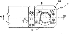
図1〜16に示す実施形態によると、重合体の一服Dを払出し出口11から移送チャンバ50への移送のため、連続的に回転する複数の取扱い手段又は第二移送手段31を有する回転する第二移送手段又は第二移送装置30を備える。各第二移送手段31は重合体の一服Dと接触することを意図した、側面が開いたU−型断面を有する凹部のある内面32bを有する。表面32bは略垂直軸に沿って軸方向へ延び、そして側面が開放し、後者の流れを表面32bと接触させることにより重合体の一服Dに付随できるチャネルを規定するような形状をしている。 According to the embodiment shown in FIGS. 1 to 16, for the transfer of the polymer dose D from the discharge outlet 11 to the transfer chamber 50, a rotating first having a plurality of handling means or a second transfer means 31 that rotate continuously. Two transfer means or a second transfer device 30 is provided. Each second transport means 31 has an inner surface 32b with a recess having a U-shaped cross section with an open side, intended to come into contact with the polymer dose D. Surface 32b extends axially along a generally vertical axis and is shaped to define a channel that can be attached to polymer dose D by contacting the latter flow with surface 32b, with the sides open. .

第二移送装置30は後者が横方向に相対移動させることにより、払出し出口11から出て来るプラスチックの一服Dを移送させ、移送チャンバ50内に1回に一つプラスチックの一服Dを配置するように取扱い手段31を順に作動させるのに適した移動手段を有する。 The second transfer device 30 moves the plastic dose D coming out from the dispensing outlet 11 by the relative movement of the latter in the lateral direction, and arranges one plastic dose D at a time in the transfer chamber 50. It has a moving means suitable for operating the handling means 31 in order.

該移動手段は図17〜20に示すようにその周縁に取扱い手段31が固定される固定軸を有する支持部46(又は図7の場合のように、シャフト47から離れたシャフト361’の周りに)と共軸の垂直シャフトの周りの鋳造機と同期して回転する水平面上に配置された円形支持部36を備える。回転方向に対して接線方向に前方に向いた表面32bの開放側面を有する取扱い手段31が配置される。 The moving means is a support portion 46 (or a shaft 361 ′ away from the shaft 47 as in FIG. 7) having a fixed shaft to which the handling means 31 is fixed at the periphery as shown in FIGS. ) And a circular support 36 arranged on a horizontal plane rotating in synchronism with the casting machine around a coaxial vertical shaft. A handling means 31 having an open side surface 32b facing forward in a tangential direction with respect to the rotational direction is arranged.

凹んだ内部接触面32bにより作られた径路P4は水平面上を走り、凹んだ内部接触面32bの上部端がナイフ13の間にある出口11の下を通過するように、払い出し出口11から近い距離(にも拘らず出口から下降する抽出体Mの下端部に対する衝撃を回避するのに十分な)そしてその下に配置される。更に該径路P4はチャンバ50の下の径路P2から近い距離でこの上に配置され、これにより凹んだ内部接触面32bの下端部がチャンバ50の上端部をブラッシングするように動く。 The path P4 made by the recessed inner contact surface 32b runs on a horizontal plane and is close to the dispensing outlet 11 so that the upper end of the recessed inner contact surface 32b passes under the outlet 11 between the knives 13. (However, it is sufficient to avoid impacts on the lower end of the extract M that descends from the outlet) and is positioned below it. Further, the path P4 is disposed on the path P2 near the lower path P2 below the chamber 50 so that the lower end portion of the recessed inner contact surface 32b moves so as to brush the upper end portion of the chamber 50.

手段31が続く径路P4は円形で、図3、5、7及び9でT2で表示される部分を有し、これが移送チャンバ50の径路P2と合致する。この部分T2の間に、各取扱い手段31は移送チャンバ50と殆ど共軸でこの上にある位置にあり、取り扱い手段31の動きは移送チャンバ50の動きに合致する。手段31が続く径路P4が真円で、手段31は支持部36へ硬く固定されているので、移送チャンバ50の径路P2は固定軌道45の径路を適切に形成することにより、円形径路から外れて、取扱い手段31の径路P4の該部分T2と一致するように作られる。 The path P4 followed by the means 31 is circular and has a portion denoted T2 in FIGS. 3, 5, 7 and 9, which matches the path P2 of the transfer chamber 50. During this portion T2, each handling means 31 is in a position almost coaxial and above the transfer chamber 50, and the movement of the handling means 31 matches the movement of the transfer chamber 50. Since the path P4 followed by the means 31 is a perfect circle and the means 31 is firmly fixed to the support portion 36, the path P2 of the transfer chamber 50 can be separated from the circular path by appropriately forming the path of the fixed track 45. , And is made to coincide with the portion T2 of the path P4 of the handling means 31.

払出し出口11は該部分T2の上流端近辺に配置される。 The payout outlet 11 is disposed near the upstream end of the portion T2.

使用の間、手段31は払出し出口11の下側を通過し、ここでナイフ13により切断されたばかりの一服Dが内部接触面32bにより形成される空洞へ入り、後者の水平運動における接触により押される。その間に一服Dは又下向き重力の力により移動し、接触面32bに沿って誘導される方法で滑り、最後に後者を離れ下の移送チャンバ50へ落下する。この移送は、部分T2に沿って運搬されこれに沿って上記のように、接触面32bは移送チャンバ50の上に殆ど共軸で配置され、同じ動きで後者と共に移動する。 During use, the means 31 passes under the dispensing outlet 11 where the sachet D just cut by the knife 13 enters the cavity formed by the internal contact surface 32b and is pushed by contact in the latter horizontal movement. . Meanwhile, the dose D also moves downward by the force of gravity, slides in a guided manner along the contact surface 32b, and finally leaves the latter and falls into the lower transfer chamber 50. This transfer is carried along the part T2, along which the contact surface 32b is arranged almost coaxially on the transfer chamber 50 and moves with the latter in the same movement.

径路P4が径路P2に合致し、その部分T2は適切な長さを有する部分T2のため及びこの部分T2における動きの一致のため、比較的長い時間が利用でき、(鋳造装置20の回転速度及び部分T2の長さにより)その間に払出し出口11から移送チャンバ50への各一服Dの正しい移送を達成することができる。 The path P4 matches the path P2 and its part T2 is available for a relatively long time because of the part T2 having the appropriate length and because of the movement matching in this part T2, (the rotational speed of the casting device 20 and In the meantime, a correct transfer of each dose D from the discharge outlet 11 to the transfer chamber 50 can be achieved (depending on the length of the part T2).

表面32bの下部33は、品物Dの解放シートへの下降を完全にするため閉じられそして収束している。 The lower part 33 of the surface 32b is closed and converged to complete the lowering of the item D to the release sheet.

図11〜14は、それらの工程は全て該合致部分T2で発生する、取り扱い手段31による払出し出口11から移送チャンバ50への重合体の一服Dの移送の主要な工程を示す。 FIGS. 11 to 14 show the main steps of the transfer of the polymer dose D from the discharge outlet 11 to the transfer chamber 50 by the handling means 31, all of which occur at the mating portion T2.

図11は表面32bの空洞へ入ったばかりの、そしてナイフ13の動作により抽出体Mか除去されたばかりの一服Dを示す。この工程は図3の位置Q1に対応する。 FIG. 11 shows a dose D that has just entered the cavity of the surface 32 b and has just been removed from the extract M by the action of the knife 13. This step corresponds to the position Q1 in FIG.

図12〜14で、重合体Dは表面32bに付帯して下降し、最後にそれは下の移送チャンバ50(図14)へ完全に入る。 12-14, the polymer D descends with the surface 32b, and finally it completely enters the lower transfer chamber 50 (FIG. 14).

図15と16はそれらの工程は全て該合致部分T1で発生する、移送チャンバ50から下の鋳型21空洞への重合体の一服Dの移送の重要な工程を示す。 FIGS. 15 and 16 show the important steps of the transfer of the polymer dose D from the transfer chamber 50 to the lower mold 21 cavity, all of which occur at the mating portion T1.

図21、22は下向きの力を発生させ、この方法で該チャンバの下部ポートを通して一服Dの出口をより迅速につくるため、一服Dの上の移送チャンバ50へ例えば空気又は他の気体のような圧縮された流体を挿入する装置の版を示す。 21 and 22 generate a downward force and, in this way, more quickly create the outlet of the dose D through the lower port of the chamber, such as air or other gas to the transfer chamber 50 above the dose D. 1 shows a version of a device for inserting a compressed fluid.

このため、下部を通して圧力により重合体の一服Dを放出するため、それを通して適切な圧縮流体払出し手段により、強制された流体がチャンバ50へ払出される、一つ以上の開口部が設けられる移送チャンバの上部ポートを閉じるのに適した第一閉鎖手段が備えられる。示された実施形態で第一閉鎖手段は、後者が鋳型空洞上に適切に重なった位置になる毎に、移送チャンバ50の上部ポートを閉鎖するように配置される閉鎖体54を備える。この重なりが発生すると、圧縮流体は開口部54aを通して送られ、本体54で確保され、そして下の一服Dを強制的に下へ押すように、移送チャンバ50の内部へ下へ向けられる。 For this purpose, a transfer chamber provided with one or more openings through which the forced fluid is discharged into the chamber 50 by means of suitable compressed fluid discharge means for releasing the polymer dose D by pressure through the lower part. A first closing means suitable for closing the upper port of the device is provided. In the embodiment shown, the first closing means comprises a closing body 54 arranged to close the upper port of the transfer chamber 50 each time the latter is properly overlaid on the mold cavity. When this overlap occurs, the compressed fluid is routed through the opening 54a, secured in the body 54, and directed down into the transfer chamber 50 to force the lower dose D down.

閉鎖本体54は第二移送装置30の回転支持ディスク36aの外縁下に固定される。該支持ディスク36aは、取扱い手段31を支持し、その外縁部が鋳型21の径路に重なるような半径で伸びる支持部36へ結合されこれに共軸である。機械30及び鋳造装置20の運動学的特徴は鋳型21の空洞上に重なる各移送チャンバ50に対し、閉鎖体54は移送チャンバ50の上部を閉じるように配置される。この工程で、圧縮流体は、重合体の一服Dが供給位置における下の鋳型空洞へ下向きに押されるように、本体54を通して挿入される。閉鎖体54はこのように移送チャンバ50から重合体の一服Dを放出するための放出手段として作動する。 The closing body 54 is fixed under the outer edge of the rotation support disk 36a of the second transfer device 30. The support disk 36a supports the handling means 31 and is coupled to and coaxial with a support portion 36 extending at a radius such that its outer edge overlaps the path of the mold 21. The kinematic features of the machine 30 and the casting apparatus 20 are such that for each transfer chamber 50 that overlies the cavity of the mold 21, a closure 54 is arranged to close the top of the transfer chamber 50. In this step, the compressed fluid is inserted through the body 54 so that the polymer dose D is pushed downward into the lower mold cavity at the delivery position. The closure 54 thus operates as a discharge means for discharging the polymer dose D from the transfer chamber 50.

図23と24に示す実施形態によると、払出し出口11から移送チャンバ50へ一服Dを移送するための第二移送装置30は、水平面上にある円形径路P5に沿って動く払出しプラスチックに適した複数の第二払出し出口16を周辺で支持する固定払出し出口11に関連する回転する回転ラックを備える。より詳しくは回転ラック15は垂直な中心軸15Aの周りで回転し、回転結合ジョイント151により固定出口11へ結合される軸上15Aに配置される上部ポート152を有する。ジョイント151は固定出口11と回転ポート152との間の流体結合の連続性を保証する。 According to the embodiment shown in FIGS. 23 and 24, the second transfer device 30 for transferring the dose D from the discharge outlet 11 to the transfer chamber 50 is suitable for a discharge plastic moving along a circular path P5 lying on a horizontal plane. A rotating rack associated with the fixed payout outlet 11 supporting the second payout outlet 16 in the periphery. More specifically, the carousel 15 rotates about a vertical central axis 15 </ b> A and has an upper port 152 disposed on the axis 15 </ b> A that is coupled to the fixed outlet 11 by a rotary coupling joint 151. The joint 151 ensures continuity of fluid coupling between the fixed outlet 11 and the rotation port 152.

回転ラック15の中に、ポート152から離れ、軸15Aに沿って延びる中央チャネル153が確保され、そして中央チャネル153の下端部から半径方向に伸びる複数の横断チャネルが確保され、そして垂直軸を備えた下向きで、回転ラック15の周辺に分布し、そして軸15Aから同じ距離に配置され、互いに同一距離に角度的に配置される同数の第二出口16を供給する。 Within the carousel 15 is secured a central channel 153 extending away from the port 152 and extending along the axis 15A, and a plurality of transverse channels extending radially from the lower end of the central channel 153 is secured and comprises a vertical axis. In the downward direction, the same number of second outlets 16 are supplied distributed around the carousel 15 and arranged at the same distance from the shaft 15A and angularly arranged at the same distance from each other.

各ポート16はプラスチックの抽出体を払出すのに適しており、抽出体を複数の一服Dへ分割するための手段がそれらの各々に関連する。例えば該分割手段はポートの中で軸方向に移動可能であり、出口16の出口孔161を閉じるのに適しており、これにより重合体抽出体を分割する閉鎖手段17である。又分割手段はナイフでもよい(図示せず)。 Each port 16 is suitable for dispensing a plastic extract, and means for dividing the extract into a plurality of doses D are associated with each of them. For example, the dividing means is axially movable in the port and is suitable for closing the outlet hole 161 of the outlet 16, thereby closing means 17 for dividing the polymer extract. The dividing means may be a knife (not shown).

対応する関連部材を備えた開示した回転ラック15は既に知られる;例えばそれは同じ出願者により出願された特許出願PCT/EP2003/07325で開示されたタイプである。 The disclosed carousel 15 with corresponding associated members is already known; for example it is of the type disclosed in the patent application PCT / EP2003 / 07325 filed by the same applicant.

移送チャンバ50の移動手段は、その径路P2は第二払出し出口16(この部分は図23にT5として表示される)の径路P5に合致する部分を有するようにチャンバ50を順に移動させるのに適し、その間に各移送チャンバ50は第二ポート16とほぼ共軸で、その下にある位置にあり、そして移送チャンバ50の動きは第二ポート16の動きに合致し、重合体の一服Dの移送チャンバ50への移送はこの部分で発生する。 The moving means of the transfer chamber 50 is suitable for moving the chamber 50 in order so that the path P2 has a portion that matches the path P5 of the second payout outlet 16 (this portion is labeled as T5 in FIG. 23). In the meantime, each transfer chamber 50 is substantially coaxial with and underneath the second port 16 and the movement of the transfer chamber 50 matches the movement of the second port 16 to transfer the polymer dose D. Transfer to the chamber 50 occurs in this part.

使用では、抽出プラスチック体は払出し出口11から絶えず下降し、チャネル153と154を通して第二ポート16へ到達する。後者は一時に1個を順に(又は数個の出口で同時に)重合体の一服Dを払出す回転ラック15の動きと同期して作動する一方、それらは該部分T5に沿って移動し、ここでそれらはチャンバ50上に正確に重ねられ、この部分の間に一服Dは動力により、下の移送チャンバ50の中に落下する。 In use, the extracted plastic body continuously descends from the discharge outlet 11 and reaches the second port 16 through the channels 153 and 154. The latter operates in synchronism with the movement of the carousel 15 which dispenses the polymer dose D one at a time (or simultaneously at several outlets) at a time, while they move along the portion T5, where They are exactly superimposed on the chamber 50, during which the dose D drops into the lower transfer chamber 50 by power.

径路P2が径路P5に合致し、その部分T5は適切な長さを有する、部分T5のため、そして部分T5に沿っての移動と一致するため、鋳造装置20の回転速度と部分T5の長さにより、比較的長時間が利用でき、その間に各第二払出し出口16から下の移送チャンバ50への一服Dの移送を達成することができる。 Because the path P2 matches the path P5, and its portion T5 has an appropriate length, because of the portion T5 and to match the movement along the portion T5, the rotational speed of the casting apparatus 20 and the length of the portion T5 Thus, a relatively long time can be used, during which the transfer of the dose D from each second dispensing outlet 16 to the lower transfer chamber 50 can be achieved.

図7と9に示すアーム手段41の実施形態で、合致部分T1、T2とT5で、移送チャンバ50の動き(軌道と速度)は先の二つの実施形態と異なり、鋳型21の動き又は夫々取扱い手段31又は第二払出し出口16の動きに正確に合致せず、それにも拘らず十分正確な方法でこのような動きに接近する。 In the embodiment of the arm means 41 shown in FIGS. 7 and 9, the movement (trajectory and speed) of the transfer chamber 50 differs from the previous two embodiments in the mating portions T1, T2 and T5, and the movement or handling of the mold 21 respectively. It does not exactly match the movement of the means 31 or the second dispensing outlet 16 and nevertheless approaches such movement in a sufficiently accurate manner.

第一移送手段50は形状及び後者については下降の間に後者の壁と接触することなく、鋳型21の空洞へ下降するのに適したプラスチックの一服Dを作りこれにより鋳型21の空洞へ正確に挿入するようなプラスチックの一服Dの夫々の寸法を幾何学的に修正するのに適した形状調整手段を備える。 The first transfer means 50 creates a plastic dose D suitable for lowering into the cavity of the mold 21 without making contact with the latter wall during the lowering of the shape and the latter, so that it accurately enters the cavity of the mold 21. Shape adjusting means suitable for geometrically modifying the respective dimensions of the plastic dose D to be inserted are provided.

形状調整手段は用途特に鋳型空洞が重合体の一服Dの質量に比べ比較的深く狭くそして/または作動速度は比較的速い場合に見出される。一般的な場合は、この場合鋳型空洞は一服の質量に対し比較的深く狭いように、ミネラルウォータ又は他の発砲飲料用の通常のプラスチックボトルを製造するために使用されるPET予備成形品の成形である。 Shape adjusting means are found in applications, particularly when the mold cavity is relatively deep and narrow compared to the mass of the polymer dose D and / or the operating speed is relatively high. In the general case, the molding of a PET preform used to produce a normal plastic bottle for mineral water or other foaming beverages, in this case the mold cavity is relatively deep and narrow relative to the mass of the dose. It is.

実施形態によると、移送チャンバ50の内部空洞の形状は重合体の一服Dの形状を幾何学的に調整する。一服Dは言換えればチャンバの内部空洞50aのそれと異なる形状の移送チャンバ50へ挿入され、一服Dがその固有流動性と可塑性により、その同じ形状、特に側面の形状を呈する物理的な意味で後者により調整される。 According to an embodiment, the shape of the internal cavity of the transfer chamber 50 geometrically adjusts the shape of the polymer dose D. In other words, the dose D is inserted into the transfer chamber 50 having a shape different from that of the inner cavity 50a of the chamber, and the latter in the physical sense that the dose D exhibits the same shape, particularly the side shape, due to its inherent fluidity and plasticity. It is adjusted by.

既に上で観察されたように、調整手段により、移送チャンバから鋳型空洞への重合体の一服の通過は、径路P2が径路P3に合致する該部分T1は必要でない程速く達成でき、その間に各移送チャンバ50は鋳型21の空洞と殆ど共軸でその上の位置にある。 As already observed above, by means of the adjustment, the passage of a polymer dose from the transfer chamber into the mold cavity can be achieved so fast that the part T1 where the path P2 coincides with the path P3 is not necessary, during which The transfer chamber 50 is almost coaxial with the cavity of the mold 21 and is in a position above it.

図11〜16、25、27、28における実施形態によると移送チャンバ50の内部空洞50aは、側壁51の内面51bにより横方向に区切られ、その表面は垂直母面を備えた円形断面の可能性もある円筒形であり、そしてその横断面寸法は鋳型空洞の入口領域の最小横断寸法より大きくはない。 According to the embodiment in FIGS. 11-16, 25, 27, 28, the internal cavity 50a of the transfer chamber 50 is laterally delimited by the inner surface 51b of the side wall 51, the surface of which can be a circular cross section with a vertical mother surface. There is also a cylindrical shape, and its cross-sectional dimension is not larger than the minimum transverse dimension of the entrance area of the mold cavity.

例えば図15と16のような表示した場合で、鋳型の上部21bの空洞は、下部21aの円筒側面より小さい直径を有する。この場合内部空洞50aの直径は上部21b空洞の直径よりやや小さい。 For example, as shown in FIGS. 15 and 16, the cavity of the upper part 21b of the mold has a smaller diameter than the cylindrical side surface of the lower part 21a. In this case, the diameter of the internal cavity 50a is slightly smaller than the diameter of the upper 21b cavity.

もし鋳型の下部21aの空洞の円筒側面が上部21bの空洞より小さい直径を有する場合、その反対が当てはまる。 The opposite is true if the cylindrical side of the cavity of the lower part 21a of the mold has a smaller diameter than the cavity of the upper part 21b.

一服Dは下の鋳型21の空洞内のチャンバ50により解放される場合、一服Dは下降の間に空洞の側壁と接触せずに空洞入ることを可能にするように、そして接触が発生しても、これが下降及び鋳型21内の一服Dの正しい位置決めを妨げないことを保証するような形状を有する。 When the dose D is released by the chamber 50 in the cavity of the lower mold 21, the dose D is allowed to enter the cavity without contact with the side walls of the cavity during the descent, and contact occurs. Also has a shape that ensures that this does not interfere with the lowering and correct positioning of the dose D in the mold 21.

内部空洞50aの横方向の寸法(直径)は、一服Dのチャンバ50への挿入をよりよく可能にするため、払い出し出口11から放出される一服Dにより想定される横方向寸法より小さくはない。 The lateral dimension (diameter) of the internal cavity 50a is not smaller than the lateral dimension assumed by the dose D discharged from the dispensing outlet 11 in order to better allow the dose D to be inserted into the chamber 50.

移送チャンバ50の内部空洞50aは円筒形の閉じた側壁51による横方向の区切りに加え、表示していない手段により、交互に開閉位置をとるのに適した下部底壁を備える第二閉鎖手段により底部で閉鎖できる。 The internal cavity 50a of the transfer chamber 50 is provided by a second closing means with a lower bottom wall suitable for taking the open / closed position alternately by means not shown, in addition to a transverse partition by a cylindrical closed side wall 51. Can be closed at the bottom.

又内部空洞50aの上部底は、表示していない手段により開閉できる上部底壁から構成される第一閉鎖手段53により閉鎖できる。 The upper bottom of the internal cavity 50a can be closed by first closing means 53 constituted by an upper bottom wall that can be opened and closed by means not shown.

移送チャンバ50が払出し出口11から重合体の一服Dを受ける工程で、上部壁53は開位置にあり、一方下部壁52は閉位置にある。移送チャンバ50が重合体の一服Dを鋳型空洞へ払出す工程の間に、上部壁53は閉位置にあり、一方下部壁52は開位置にある。 In the process where the transfer chamber 50 receives the polymer dose D from the discharge outlet 11, the upper wall 53 is in the open position, while the lower wall 52 is in the closed position. During the process in which the transfer chamber 50 dispenses the polymer dose D into the mold cavity, the upper wall 53 is in the closed position, while the lower wall 52 is in the open position.

表示した実施形態で、下部底壁52は平坦で閉位置にあり、水平面上にある。開位置に到達するため、下部底壁52は側壁51の下部エッジに近い同じ該水平面に沿って動く。特に該下部底壁52は、垂直軸を有し、壁51に結合されたピボット521の周りで側壁51に対し回転する。 In the illustrated embodiment, the lower bottom wall 52 is flat and in a closed position and is on a horizontal plane. In order to reach the open position, the lower bottom wall 52 moves along the same horizontal plane close to the lower edge of the side wall 51. In particular, the lower bottom wall 52 has a vertical axis and rotates relative to the side wall 51 about a pivot 521 coupled to the wall 51.

同様に、上部底壁53は平坦で、開位置へ行くため、それはそれが閉位置にある水平面上に留まるように動く。特に上部底壁53は、壁51に結合され、垂直軸を有するピボット531の周りの側壁51に対して回転する。 Similarly, since the top bottom wall 53 is flat and goes to the open position, it moves so that it remains on the horizontal plane in the closed position. In particular, the top bottom wall 53 is coupled to the wall 51 and rotates relative to the side wall 51 around a pivot 531 having a vertical axis.

重合体の一服Dは移送チャンバ50の空洞50aの内面、特に下部壁52の内部側面51b及び内面52bと接触するので、チャンバ50は重合体の一服Dと内部接触面との間の付着影響を削減する様に、この接触により起こされる付着を完全に又は部分的に削減するための付着防止手段を備える。 Since the polymer dose D contacts the inner surface of the cavity 50a of the transfer chamber 50, in particular the inner side surface 51b and the inner surface 52b of the lower wall 52, the chamber 50 has an adhesion effect between the polymer dose D and the inner contact surface. In order to reduce, an adhesion prevention means is provided for completely or partially reducing the adhesion caused by this contact.

図25に示す移送チャンバ50の実施形態によると、該付着防止手段は、流体、特に気体、例えば空気をチャンバ50の空洞へ供給するのに適した払出し手段を備える。放出された流体は移送チャンバ50の内面と重合体の一服Dとの間にギャップを形成する。 According to the embodiment of the transfer chamber 50 shown in FIG. 25, the anti-adhesion means comprises a discharge means suitable for supplying a fluid, in particular a gas, for example air, to the cavity of the chamber 50. The discharged fluid forms a gap between the inner surface of the transfer chamber 50 and the polymer dose D.

移送チャンバ50の側壁51と下部底壁52は、その厚さを通して流体が通過できるように多孔質であることが望ましい。この場合、側壁51の外にありこれと共軸で側壁51を囲み、上部と下部エッジで後者へ接続される第二側壁51’が備えられる。二つの壁51と51´の間に、多孔質側壁51を360度取り囲み、そしてその全高さ又は殆ど全高さに沿って延びる側面チャンバ51aが規定される。側面チャンバ51aは図には表示されない、チャネル59と入口56を通して圧縮気体を該チャンバ51aへ、そしてそこから多孔質壁51を通して移送チャンバ50の中へ送るのに適した手段と結合される。 The side wall 51 and the lower bottom wall 52 of the transfer chamber 50 are preferably porous so that fluid can pass through their thickness. In this case, a second side wall 51 'is provided which is outside the side wall 51 and surrounds the side wall 51 coaxially therewith and is connected to the latter at the upper and lower edges. A side chamber 51a is defined between the two walls 51 and 51 'that surrounds the porous sidewall 51 360 degrees and extends along its full height or almost its full height. Side chamber 51a is coupled to means not shown in the figure, suitable for delivering compressed gas through channel 59 and inlet 56 to chamber 51a and from there through porous wall 51 into transfer chamber 50.

下部壁52の下に配置され、外部エッジに沿って後者に連結される第二外部底壁52’が更に備えられる。二つの壁52と52’の間で、薄い下部チャンバ52aは底壁52の全範囲に延び、又圧縮気体をチャンバ52aへ、そしてそこから多孔質壁52を通して移送チャンバ50の中へ送るのに適した手段と結合される。 A second outer bottom wall 52 'is further provided disposed below the lower wall 52 and connected to the latter along the outer edge. Between the two walls 52 and 52 ′, the thin lower chamber 52 a extends over the entire area of the bottom wall 52 and also allows compressed gas to flow into the chamber 52 a and from there through the porous wall 52 into the transfer chamber 50. Combined with suitable means.

圧縮気体はチャンバ51a、52aへ送られそして壁52と51の内面52bと51bと重合体の一服Dの外面との間に介在する気体のギャップ又は層を形成するため、ここから多孔質の壁52と51を通って通過する。気体で充填されたギャップは重合体の一服Dと壁52と51との間の接触を回避し、又は、少なくとも接触領域の時間と程度を削減し、これにより重合体の一服Dと壁52、51との間の肉眼でッ見える付着影響を削減し、一服の効果的な下降流を促進する効果を有する。 The compressed gas is sent to the chambers 51a, 52a and from there to form a gas gap or layer interposed between the inner surfaces 52b and 51b of the walls 52 and 51 and the outer surface of the polymer dose D, from which porous walls are formed. Pass through 52 and 51. The gas-filled gap avoids contact between the polymer dose D and the walls 52 and 51, or at least reduces the time and extent of the contact area, whereby the polymer dose D and the wall 52, This reduces the effect of adhesion with the eye 51 and promotes effective downflow of a dose.

接触面と重合体の一服Dとの間の十分な圧力と流量率値(用途により変動し、とにかく比較的容易に検証可能な)で充填されたギャップを介在することにより、後者は実際固着せず、表面に付着したままにならない程度に重合体の一服Dの付着影響を完全に又は少なくとも部分的に削減することが可能となる。 By interposing a gap filled with sufficient pressure and flow rate values between the contact surface and the polymer dose D (which varies depending on the application and can be verified relatively easily anyway), the latter is actually fixed. Therefore, it is possible to completely or at least partially reduce the adhesion effect of the polymer dose D to the extent that it does not remain attached to the surface.

事実一般に比較的低い(1又は数バールで十分)適切な流量率及び圧力値の流体で充填されたギャップを形成することにより、重合体の一服Dと接触面との間の接触が回避される。もしそれにも拘らず接触が発生すれば、それはとにかく局部的で時間的にも限定される。この点に関して、重合体の一服Dと表面との間の接触時間を比較的低い値に限定することにより、対応して低い肉眼で見える付着影響が得られる。もし付着時間が数マイクロ秒であれば、肉眼で見える付着の効果は実際上はゼロである。 In fact, contact between the polymer dose D and the contact surface is generally avoided by forming a gap filled with a fluid of a relatively low (one or a few bars is sufficient) appropriate flow rate and pressure value. . If contact nevertheless occurs, it is limited locally and limited in time. In this regard, by limiting the contact time between the polymer dose D and the surface to a relatively low value, a correspondingly low visible adhesion effect is obtained. If the adhesion time is several microseconds, the effect of adhesion visible to the naked eye is practically zero.

この現象は以下の事実により説明できる。即ち付着影響を得るため、化学物理的付着力が効果を表すようにある値(反応時間)より短くない接触時間が必要である。この反応時間は材料、温度及び局部圧力の関数である。流体で充填されたギャップはこのプロセスを絶えず中断させ、それにより最大の付着が起こらず、接触が全て回避される。 This phenomenon can be explained by the following facts. That is, in order to obtain an adhesion effect, a contact time not shorter than a certain value (reaction time) is required so that the chemical physical adhesion force exhibits an effect. This reaction time is a function of material, temperature and local pressure. A fluid filled gap continually interrupts the process so that maximum adhesion does not occur and all contact is avoided.

その孔は5×10⁻³mmと20×10−3mmの間の直系を有する材料から該多孔質壁を作り、そしてチャンバ51aと52aへ0.5〜1バールの圧力の気体を送り込むことにより優れた結果が得られた。 The pores make the porous wall out of a material having a direct line between 5 × 10 −3 mm and 20 × 10 −3 mm and feed a gas with a pressure of 0.5 to 1 bar into the chambers 51a and 52a. Excellent results were obtained.

図31は図25の移送チャンバ50の動作を示す。チャンバ50は、例えば払出し出口11(位置P1)の下で殆ど共軸のような一服Dをそれが受ける第一位置に最初配置される。続いてチャンバ50は鋳型空洞上、特にチャンバ50が重合体の一服Dを解放する鋳型空洞上でこれと殆ど共軸である位置に配置される第二位置P2’へ移動する。 FIG. 31 shows the operation of the transfer chamber 50 of FIG. The chamber 50 is initially placed in a first position in which it receives a dose D, for example almost coaxial, under the dispensing outlet 11 (position P1). The chamber 50 is then moved to a second position P2 'which is located on the mold cavity, in particular on the mold cavity where the chamber 50 releases the polymer dose D, at a position which is almost coaxial.

チャンバ50の動きは相対的で、即ちこの動きはプラスチック供給手段が静止中及び鋳型が動いている間にチャンバの移動に続いて、又は動きの他の異なる組み合わせにより発生する。 The movement of the chamber 50 is relative, i.e. this movement occurs following the movement of the chamber while the plastic supply means is stationary and the mold is moving, or by other different combinations of movement.

移動チャンバ50は払出し出口11から一服Dを受ける工程の間、上部壁53は開位置にあり、一方下部壁52は閉位置にある。移送チャンバ50が重合体の一服を鋳型空洞へ解放する工程において、上部壁53は開位置にあり、一方下部壁52は閉位置にある。下部底壁52が開で一方、上部底壁53は閉に保たれる場合、移送チャンバ50は重合体の一服Dの鋳型空洞への下降を実施するため位置P2’にある該フェーズにおいて、壁51と53を通してチャンバ50へ放出された圧縮気体は一服Dを下の鋳型内へ迅速に効果的に押す「ショット」効果を生成する。 During the process in which the transfer chamber 50 receives the dose D from the dispensing outlet 11, the upper wall 53 is in the open position, while the lower wall 52 is in the closed position. In the process where the transfer chamber 50 releases the polymer dose to the mold cavity, the upper wall 53 is in the open position while the lower wall 52 is in the closed position. When the bottom bottom wall 52 is open while the top bottom wall 53 is kept closed, the transfer chamber 50 is in the phase at position P2 ′ to effect the lowering of the polymer dose D into the mold cavity. The compressed gas released through 51 and 53 into the chamber 50 creates a “shot” effect that quickly and effectively pushes the dose D into the lower mold.

図26に示すように、代わって多孔質の壁へ非多孔質材の壁を備えることができ、ここでそれにも拘らず多数の小孔57が、例えば後者を通して流体の通過を可能にし、該小孔57は重合体の一服Dとの接触が発生する領域上に分布されるように備えられる。例えばこれらの孔57は接触領域上で可能な最大のカバーを達成するため、らせん状分布を有する。更なる代案によると、多孔質壁は、接触領域で適切な方法で成形され、そして分布され、そしてそれを通して流体を流す複数の比較的薄い相互分離線を後者が発生するように、接合された複数の要素により作られる壁により置換される。 As shown in FIG. 26, a porous wall can alternatively be provided with a non-porous material wall, where nonetheless a large number of small holes 57 allow passage of fluid, for example through the latter, The small holes 57 are provided so as to be distributed over a region where contact with the polymer dose D occurs. For example, these holes 57 have a helical distribution to achieve the maximum possible cover on the contact area. According to a further alternative, the porous walls are shaped and distributed in a suitable manner in the contact area and joined so that the latter generates a plurality of relatively thin lines of separation through which fluid flows. Replaced by a wall made of multiple elements.

流体で充填されたギャップにより生成されたこの開示された好ましい効果は、重合体の一服Dの表面のそして/または接触面の温度を下げるように接触面と重合体の一服Dとの間に送られた流体を熱的に調整することにより更に強調される。 This disclosed preferred effect produced by the fluid-filled gap can be delivered between the contact surface and the polymer dose D to reduce the temperature of the surface of the polymer dose D and / or the contact surface. Further emphasis is made by thermally adjusting the fluid produced.

このため、その温度を下げるような方法で、流体又は気体を熱的に調整するのに適した手段を備えることができる(図示なし)。このような場合、移送チャンバ50の内面と重合体の一服Dの外面との間に形成された気体で充填されたギャップもまた壁52と51の質量及び重合体の一服Dの外面との効果的な熱交換を生成し、この熱交換は重合体の一服Dの流れを促進するために使用できる。冷却された流体は、壁を通して通過することにより、又は接触面51bと52b及び重合体の一服Dの表面の両方を簡単にこすることにより少なくとも表面的にその温度を下げ、これにより重合体の一服Dの粘度を増加させ、これによりプラスチックの付着を減少させる。事実、もし接触時間が増加すれば(マイクロ秒からミリ秒迄通して)、壁温は付着防止のため下げなければならないことが発見されている。接触面が多孔質材でできた壁上に配置される、上で開示した場合、又はもし流体が比較的狭い開口部を横断するならば、流体は壁を通過して、出るときに後者の膨張により、それ自身好ましい「冷却効果」を有する。明らかに、流体の温度は、材料の微結晶化又とにかくは材料の不規則性の芽を生成するような例え局部的でも重合体の一服Dの過冷却を回避するように調節される。いずれの場合でも、流体により生成された重合体の一服の量への冷却効果は一服の取扱い手段の接触面と一服との直接の、比較的長い物理的接触により達成されたそれと完全に異なる。事実、先の場合でプラスチックの一服Dの最表面層のみに影響する一種の微冷却があり、そしてそれは規則的かつ均一にその表面全体にわたり分布される。一方重合体の一服Dと取扱い手段との間の接触の場合には、先に述べたように成形品にとって有害な結果となる一服の比較的小部分に限定された強い、比較的深い冷却が起こる。 For this reason, it is possible to provide means (not shown) suitable for thermally adjusting the fluid or gas in such a way as to reduce its temperature. In such a case, the gas-filled gap formed between the inner surface of the transfer chamber 50 and the outer surface of the polymer dose D also affects the mass of the walls 52 and 51 and the outer surface of the polymer dose D. Heat exchange, which can be used to facilitate the flow of polymer dose D. The cooled fluid lowers its temperature at least superficially by passing through the wall or by simply rubbing both the contact surfaces 51b and 52b and the surface of the polymer dose D, so that the polymer Increase the viscosity of the dose D, thereby reducing plastic adhesion. In fact, it has been discovered that if the contact time increases (from microseconds to milliseconds), the wall temperature must be lowered to prevent adhesion. The contact surface is disposed on a wall made of porous material, if disclosed above, or if the fluid traverses a relatively narrow opening, the fluid will pass through the wall and the latter when exiting. Due to the expansion, it itself has a favorable “cooling effect”. Obviously, the temperature of the fluid is adjusted so as to avoid supercooling of the polymer dose D, even locally, such as producing microcrystallisation of the material or any irregular buds of the material. In any case, the cooling effect on the dose of polymer produced by the fluid is completely different from that achieved by direct, relatively long physical contact between the contact surface of the dose handling means and the dose. In fact, in the previous case, there is a kind of microcooling that only affects the outermost surface layer of the plastic dose D, and it is distributed regularly and uniformly over the entire surface. On the other hand, in the case of contact between the polymer dose D and the handling means, there is a strong, relatively deep cooling limited to a relatively small portion of the dose that results in harmful effects to the molded product as described above. Occur.

又、表面に対してこするギャップが発生するように接触面51b、52bの接線方向の流れの気体が移送チャンバ50の中へ送られる。チャンバ50内の圧縮された気体の存在もまた、重合体の一服Dの鋳型21の空洞へ下降させるため、移送チャンバ50が部分T1にある工程において重要な有利な効果も有する。下部底壁52が開で、一方上部底壁53が閉に保持される場合、壁51と53を通してチャンバ50へ放出された圧縮された気体は、下の鋳型空洞へ一服Dを迅速かつ効果的に押す「ショット」効果を生成する。この好ましい効果は例えば上で開示したように多孔質の壁51を備えることにより、異なる方法でチャンバ50に気体を送ることにより確保される。この効果は図26に示す、また上部底壁53に備えられた一つ以上の開口部57を通して気体を送ることにより増加する。該気体は鋳型空洞内で重合体の一服Dを下方向へ押すために使用される。 Further, a gas flowing in a tangential direction of the contact surfaces 51 b and 52 b is sent into the transfer chamber 50 so that a gap rubbing against the surface is generated. The presence of the compressed gas in the chamber 50 also has an important advantageous effect in the process in which the transfer chamber 50 is in part T1, since it is lowered into the cavity of the mold 21 of the polymer dose D. When the lower bottom wall 52 is open, while the upper bottom wall 53 is held closed, the compressed gas released into the chamber 50 through the walls 51 and 53 quickly and effectively delivers a dose D to the lower mold cavity. Generates a “shot” effect that presses into. This favorable effect is ensured by sending gas to the chamber 50 in a different way, for example by providing a porous wall 51 as disclosed above. This effect is increased by sending gas through one or more openings 57 provided in the upper bottom wall 53 as shown in FIG. The gas is used to push the polymer dose D downward in the mold cavity.

又該効果は又多孔質材の上部底壁53を作り、そしてチャンバ50へ後者を通して気体を送ることにより確保される。詳細には、図25に示すように、壁53の外にあり、この上に配置されそして外エッジに沿って後者に結合される第二の底壁53´が備えられる。二つの壁53と53´の間に底壁53の全範囲にわたり延びる薄い上部チャンバ53aが規定され、下部底壁52が開の工程で、これが次に圧縮された気体をチャンバ53aへ、そこから多孔質壁53を通して移送チャンバ50へ送るのに適した手段に結合される。 The effect is also ensured by creating an upper bottom wall 53 of porous material and sending gas through the latter to the chamber 50. Specifically, as shown in FIG. 25, there is provided a second bottom wall 53 'that is outside of the wall 53, disposed on it and joined to the latter along the outer edge. A thin upper chamber 53a is defined between the two walls 53 and 53 'that extends over the entire area of the bottom wall 53, and in the process of opening the lower bottom wall 52, this is followed by the compressed gas to the chamber 53a. Coupled to means suitable for delivery to the transfer chamber 50 through the porous wall 53.

又図26に示すように、重合体の一服Dを下方へ押すため、流体をチャンバ50へ送るため、又大きな直径の一つ以上の開口部57が上部底壁53に備えることができる。 Also, as shown in FIG. 26, one or more openings 57 of large diameter can be provided in the upper bottom wall 53 to push the polymer dose D downward, to send fluid to the chamber 50.

図27は図25のそれと略同一の移送チャンバ50の版を示し、それは上部底壁53が多孔質の代わりに流体をチャンバ50へ送り、重合体の一服Dを下方ヘ押すために、又大きな直径の一つ以上の開口部57を提供する事実によりそれと異なる。 FIG. 27 shows a version of the transfer chamber 50 that is substantially identical to that of FIG. 25, where the top bottom wall 53 sends fluid to the chamber 50 instead of being porous, and is also large to push the polymer dose D downward. It differs from that by the fact that it provides one or more openings 57 of diameter.

図29に示す版は図26の移送チャンバ50に略同じでそれは下部底壁52は多孔質でないが、側壁51のように流体の通過のための多くの小孔57’又は複数の薄い分離線を備える。上部底壁53は一つ以上の開口部を有する。 The plate shown in FIG. 29 is substantially the same as the transfer chamber 50 of FIG. 26, although the lower bottom wall 52 is not porous, but, like the side wall 51, many small holes 57 ′ or a plurality of thin separation lines for passage of fluid. Is provided. The upper bottom wall 53 has one or more openings.

又図32に示すように、上部底壁53は備えられない。このような場合、重合体の一服Dが寸法特に鋳型21の空洞のそれらより小さいか又は同等である直径寸法を有するので、重合体の一服Dは、重力によりこの空洞内へ落下できる。 Further, as shown in FIG. 32, the upper bottom wall 53 is not provided. In such a case, the polymer dose D can fall into this cavity by gravity, since the polymer dose D has dimensions, in particular a diameter dimension that is smaller or equivalent to those of the cavity of the mold 21.

図32の版において、下部底壁52は一体鋳造ではないが垂直軸を有する壁51に結合された夫々のピボットの周りの側壁51に対して回転可能な二つの要素525から構成される。二つの要素525はそれらが閉位置へ結合されるまで回転する場合、チャンバ50の出口を塞ぎ、そして多孔質壁52を形成する。一方二つの要素は外部に向かって開位置へ回転する場合、一服Dが出ることを可能にする。 In the version of FIG. 32, the bottom bottom wall 52 is comprised of two elements 525 that are rotatable with respect to the side walls 51 about their respective pivots that are not integrally cast but are joined to a wall 51 having a vertical axis. When the two elements 525 rotate until they are coupled to the closed position, they block the outlet of the chamber 50 and form a porous wall 52. On the other hand, the two elements allow the dose D to come out when rotating outward into the open position.

又下部壁52は備えられない。この場合図37に示すように、下部壁52を欠くことは、気体が重合体の一服Dをぶら下げたままにして、移送チャンバから後者の下降を防ぐように、気体払出し特殊な方法により補償される。重合体の一服Dが鋳型空洞へ下降するようにしなければならない場合、この動作は明らかに停止される。特に図37において側壁51が連続し、多孔質でないチャンバ50が示される。チャンバ50は下部底壁を避け、そして重合体の一服Dの下降を防止するため、ループ状導管511を備え、チャンバ50の下部出口周辺で側壁51の下部エッジの下に配置され、重合体の一服Dが出るのを妨げないような空気圧式支持手段が備えられる。導管511は、適切な方向の開口部513を通してチャンバ50の下部出口の中へ上方へ向けられた流体のジェットを発生させるように、一つ以上の入口512により圧縮流体が提供される。放出流体の圧力を適切に調整することにより、チャンバ50内に重合体の一服Dをぶら下げたままに保持し、一服Dが下部出口を通って下降することを防ぐことができる。本来導管511への流体の供給は、一服Dの下降を停止したい場合に払出され、逆に一服Dの下降を達成したい場合、供給は中断される。 The lower wall 52 is not provided. In this case, as shown in FIG. 37, the lack of the lower wall 52 is compensated by a special method of gas discharge so that the gas remains hanging the polymer dose D and prevents the latter from descending from the transfer chamber. The If the polymer dose D has to be lowered into the mold cavity, this operation is clearly stopped. In particular, in FIG. 37, a side wall 51 is continuous and a non-porous chamber 50 is shown. The chamber 50 is provided with a looped conduit 511 to avoid the lower bottom wall and to prevent the polymer dose D from descending, and is disposed around the lower outlet of the chamber 50 and below the lower edge of the side wall 51, Pneumatic support means are provided so as not to prevent the dose D from coming out. The conduit 511 is provided with compressed fluid by one or more inlets 512 so as to generate a jet of fluid directed upwardly into the lower outlet of the chamber 50 through an opening 513 in the appropriate direction. By appropriately adjusting the pressure of the discharge fluid, the polymer dose D can be held hanging in the chamber 50 and the dose D can be prevented from descending through the lower outlet. Originally, the supply of fluid to the conduit 511 is dispensed when it is desired to stop the lowering of the dose D, and conversely, when it is desired to achieve the lowering of the dose D, the supply is interrupted.

流体は又一服Dの接触面への付着を防止するため、流体で充填したギャップをまた生成するように適切な方向に向けられる。 The fluid is also oriented in an appropriate direction to also create a fluid-filled gap to prevent the dose D from sticking to the contact surface.

重合体の一服Dの形状調整に適した移送手段で図30に示す実施形態によると、移送チャンバ30を区切る凹んだ側壁は例えば一服Dを横向きに挿入するための側面開口部520を有する。チャンバ50は、一服の形状を調整するため側面開口部520を通して一服Dに対して、圧縮流体を側壁51の内面51bに向けて放出するのに適した空気圧式成形手段を備える。特にチャンバ50の側壁51は「U」型断面を有し、二つの自由端で、それは表示していない圧縮流体源へチャネル522により結合された二つの垂直導管521’を有する。垂直導管521’は開口部520に向かって流体ジェットを放出するのに適した数個の開口部523を備える。このようにして、重合体の一服Dは、流体層が介在する側壁51との接触及び開口部523により放出される流体の動的作用の両方により調整される。 According to the embodiment shown in FIG. 30 with a transfer means suitable for adjusting the shape of the polymer dose D, the recessed side walls delimiting the transfer chamber 30 have side openings 520 for inserting the dose D sideways, for example. The chamber 50 comprises pneumatic forming means suitable for releasing compressed fluid toward the inner surface 51b of the side wall 51 against the dose D through the side opening 520 to adjust the shape of the dose. In particular, the side wall 51 of the chamber 50 has a “U” shaped cross-section and has two free ends, two vertical conduits 521 ′ coupled by channels 522 to a source of compressed fluid not shown. The vertical conduit 521 'comprises several openings 523 suitable for emitting a fluid jet towards the openings 520. In this way, the polymer dose D is adjusted both by contact with the side wall 51 where the fluid layer is interposed and by the dynamic action of the fluid released by the opening 523.

図26に示す、重合体の一服Dの形状調整のための異なる実施形態によると、圧空成形手段が備えられる。その幾何学的形状を調整するため、圧縮流体を移送チャンバ50へ放出するのに適した、重合体の一服Dの側面へ作用する空気圧式移送チャンバ50は図25のそれと略同じであるが、それにも拘らず、多孔質の代わりに壁51は孔より大きい直径の複数の孔を有し、それを通して例えば空気のような圧縮流体が内部空洞50aへ挿入され、後者の形状を調整するように重合体の一服Dの側面に対して向けられる。特に一服Dの断面直径は、後者がその壁と接触することなく鋳型21の空洞へ下降するのに適するようにする方法で削減される。 According to a different embodiment for adjusting the shape of the polymer dose D shown in FIG. 26, a pressure forming means is provided. A pneumatic transfer chamber 50 acting on the side of the polymer dose D, suitable for releasing compressed fluid into the transfer chamber 50 to adjust its geometry, is substantially the same as that of FIG. Nevertheless, instead of being porous, the wall 51 has a plurality of holes with a diameter larger than the holes through which a compressed fluid, such as air, is inserted into the internal cavity 50a to adjust the shape of the latter. Directed against the side of the polymer dose D. In particular, the cross-sectional diameter of the dose D is reduced in a way that makes it suitable for the latter to descend into the cavity of the mold 21 without contacting its walls.

この解決法によると、後者の物理的特性を変更することなく、チャンバ50へ挿入された流体の特性だけ変化させ、調節可能な方法で一服Dの形状を調整することが可能である。同じ孔57はまたとりわけ鋳型空洞へのその移送で、重合体の一服Dを鋳型空洞へ押し下げるために、上部底53上に備えられる。 According to this solution, it is possible to adjust the shape of the dose D in an adjustable manner by changing only the properties of the fluid inserted into the chamber 50 without changing the physical properties of the latter. The same hole 57 is also provided on the top bottom 53 to push the polymer dose D down into the mold cavity, especially on its transfer to the mold cavity.

図33と34に示す移送チャンバ50で、付着防止手段は重合体の一服Dと移送チャンバ50の内面との間の付着を全て又は一部削減するために備えられる。 In the transfer chamber 50 shown in FIGS. 33 and 34, adhesion prevention means are provided to reduce all or part of the adhesion between the polymer dose D and the inner surface of the transfer chamber 50.

この場合、チャンバ50及び特にその内面51b、52bは重合体の一服Dと内面との間の肉眼で見える付着影響を防止又は少なくとも部分的に削減するような周波数値で振動する。事実たとえプラスチックが固着していても、たとえプラスチックが肉眼で見えるレベルで付着点を生成してもそれにも拘らず、これらの付着点は非常に小さい範囲で、とりわけ非常に短時間に留まるため、材料と接触面との間の付着の肉眼で見える力は比較的非常に小さく、このような接触面51bと重合体の一服との間の付着現象は非常に削減される、という事実が見出されている。詳細には、図33と34に示す実施形態で、重合体の一服Dと内面51b、52bとの間の付着影響を回避し又は少なくとも削減するような周波数値で移送チャンバ50を振動させるのに適した振動発生器が移送チャンバ50の外面に対し適用される。 In this case, the chamber 50 and in particular its inner surfaces 51b, 52b vibrate at a frequency value so as to prevent or at least partially reduce the adhesion effects visible to the naked eye between the polymer dose D and the inner surface. In fact, even if the plastic is stuck, even if the plastic generates attachment points at a level that is visible to the naked eye, these attachment points remain in a very small range, especially in a very short time, The fact that the visible force of adhesion between the material and the contact surface is relatively very small, and the phenomenon of such adhesion between the contact surface 51b and the polymer dose is found to be greatly reduced. Has been. Specifically, in the embodiment shown in FIGS. 33 and 34, to vibrate the transfer chamber 50 at a frequency value that avoids or at least reduces the adhesion effects between the polymer dose D and the inner surfaces 51b, 52b. A suitable vibration generator is applied to the outer surface of the transfer chamber 50.

PETプラスチックの場合300パスク/秒の周波数で移送チャンバ50の垂直軸に直角な平面上で作動する振動励起により優れた結果が得られている。 In the case of PET plastics, excellent results have been obtained with vibration excitation operating on a plane perpendicular to the vertical axis of the transfer chamber 50 at a frequency of 300 Pask / sec.

図には示されていない移送チャンバ50の更なる実施形態が、重合体の一服Dと移送チャンバ50の内面との間の付着を完全に又は部分的に削減するため、チャンバ50の空洞50aの内面を覆うように配置された付着防止コーティングの薄い層を提供し、該薄い層は例えばPTFE(登録商標テフロン)のような重合体の一服Dに関して付着防止特性を有する材料で出来ており、その外面は重合体の一服Dとの該接触面を規定する。 Since a further embodiment of the transfer chamber 50, not shown in the figure, completely or partially reduces the adhesion between the polymer dose D and the inner surface of the transfer chamber 50, the cavity 50a of the chamber 50 Providing a thin layer of an anti-adhesion coating disposed over the inner surface, the thin layer being made of a material having anti-adhesive properties with respect to a polymer dose D such as, for example, PTFE® The outer surface defines the contact surface with the polymer dose D.

図35に示す移送チャンバ50の版は、底壁52、53はその厚さを通して液体又は気体の通過を可能にするため多孔質であるという事実により図34のそれとは異なる。 The version of transfer chamber 50 shown in FIG. 35 differs from that of FIG. 34 by the fact that the bottom walls 52, 53 are porous to allow the passage of liquid or gas through their thickness.

図36の版は、上部底壁53は多孔質ではないが、流体の通過のため一つ以上の開口部57を有するという事実により図35とは異なる。 The version of FIG. 36 differs from FIG. 35 due to the fact that the top bottom wall 53 is not porous, but has one or more openings 57 for the passage of fluid.

図38、39及び40に示す手段31の実施形態によると、取扱い手段は一服Dとそれと一服Dが接触する内面32bとの間の付着を完全に又は部分的に削減するための付着防止手段を備える。 According to the embodiment of the means 31 shown in FIGS. 38, 39 and 40, the handling means comprises anti-adhesion means for completely or partially reducing the adhesion between the dose D and the inner surface 32b with which the dose D contacts. Prepare.

手段31は側面上に開いた局面壁32を備え、その内面は接触面32bを規定する。壁32の下部端部33は円形で閉じており、下向きに少し収束する軸部を有する。 The means 31 comprises an open wall 32 on the side, the inner surface of which defines a contact surface 32b. The lower end 33 of the wall 32 is circular and closed, and has a shaft that converges slightly downward.

手段31は、一服Dと内面との間の付着影響を完全に又は部分的に削減するため、内面32bに沿って、例えば気体のような流体のギャップ又は層を形成するのに適した払出し手段を備える。 The means 31 is a dispensing means suitable for forming a fluid gap or layer, for example a gas, along the inner surface 32b in order to completely or partially reduce the adhesion effect between the dose D and the inner surface. Is provided.

特に曲面壁32(その下部33を含む。)はそれを通して気体の通過を可能とするように多孔質であり、更に曲面壁32の外側にあり、これと共軸の第二管状壁を備え、第二管状壁320の下部及び上部端は曲面壁32へ結合される。二つの壁32と320の間に曲面多孔質壁を囲み、全長またはその殆ど全長に沿って延びるチャンバ34が規定され、該チャンバ34はチャンバ34内に圧縮気体を送り、その気体は接触面32bから出ることに適した手段38(図40には一部表示)と結合される。 In particular, the curved wall 32 (including its lower portion 33) is porous so as to allow the passage of gas therethrough and further comprises a second tubular wall that is outside the curved wall 32 and coaxial therewith, The lower and upper ends of the second tubular wall 320 are coupled to the curved wall 32. A chamber 34 is defined that encloses the curved porous wall between the two walls 32 and 320 and extends along the entire length or almost the entire length of the chamber 34. The chamber 34 feeds compressed gas into the chamber 34, which gas is in contact with the contact surface 32b. Combined with means 38 (partially shown in FIG. 40) suitable for exiting.

チャンバ34は夫々導管35’と導管35”により供給される上部34’と下部34”に分割され、それらの導管は一服Dの下降をよりよく制御することを可能にするため、異なる圧力特性を有する流体チャンバ34の二つの部分への供給を可能にするように分離される。 The chamber 34 is divided into an upper part 34 'and a lower part 34 "supplied by a conduit 35' and a conduit 35", respectively, which allow different control of the pressure characteristics in order to allow better control of the lowering of the dose D. The fluid chambers 34 are separated to allow supply to the two parts.

移送チャンバ50に関して上で開示した特徴を有する多孔質材で形成された壁32で優れた結果が得られた。更に上で述べたものと同様に、上で開示した特徴と結果で、その温度を下げるように気体を熱的に調整するのに適した手段(図では表示無し)が備えられる。 Excellent results have been obtained with a wall 32 formed of a porous material having the characteristics disclosed above with respect to the transfer chamber 50. Further to the features and results disclosed above, similar to those described above, means (not shown in the figure) suitable for thermally adjusting the gas to reduce its temperature are provided.

又、気体が表面に対し接線方向の流れにより接触面32bへ送ることができ、それにより表面と接触するギャップが発生する。 Further, the gas can be sent to the contact surface 32b by a tangential flow with respect to the surface, thereby generating a gap in contact with the surface.

取扱い手段31の接触面32bと重合体の一服Dとの間の液体で充填されたギャップは移送チャンバ50に関して上で開示した好ましい効果を生成する。 The gap filled with liquid between the contact surface 32b of the handling means 31 and the polymer dose D produces the advantageous effect disclosed above with respect to the transfer chamber 50.

図41と42は一服Dと取扱い手段31の内面32bとの間の付着を完全に又は部分的に削減するための付着防止手段の代わりの実施形態を示す。取り扱い手段31及び特にその内面32bは一服Dと内面との間の肉眼で見える付着影響を回避するか又は少なくとも部分的に削減するような周波数値で振動する。 41 and 42 show an alternative embodiment of an anti-adhesion means for completely or partially reducing the adhesion between the dose D and the inner surface 32b of the handling means 31. FIG. The handling means 31 and in particular its inner surface 32b vibrate at a frequency value so as to avoid or at least partially reduce the adhesion effects visible between the dose D and the inner surface with the naked eye.

詳細には、図41と42に示す実施形態で、一服Dと内面32bとの間の付着影響を防止又は少なくとも削減するような周波数値で曲面壁32を振動させるのに適した振動発生手段55が取扱い手段31の外面に対して適用される。 Specifically, in the embodiment shown in FIGS. 41 and 42, the vibration generating means 55 suitable for vibrating the curved wall 32 at a frequency value that prevents or at least reduces the adhesion effect between the dose D and the inner surface 32b. Is applied to the outer surface of the handling means 31.

又、一服Dと取扱い手段31の内面32bとの間の付着を完全に又は部分的に削減するため、曲面壁32の内面上に配置される薄い被膜層が備えられ、該薄い層は例えばPTFE(登録商標テフロン)のような一服Dに関して付着防止特性を有する材料で出来ており、その外面は一服との該接触面を規定する。 In addition, in order to completely or partially reduce the adhesion between the dose D and the inner surface 32b of the handling means 31, a thin coating layer is provided which is arranged on the inner surface of the curved wall 32, for example PTFE. It is made of a material having anti-adhesive properties with respect to a dose D such as (registered trademark Teflon), and its outer surface defines the contact surface with the dose.

図65〜70は、払出し手段10の下部面12上にある、下部位置に配置された払出し出口又はポート11からプラスチックの一服を供給するのに適した一服の払出し手段10を備える。 FIGS. 65-70 comprise a single dose dispensing means 10 suitable for dispensing a plastic dose from a dispensing outlet or port 11 located in a lower position on the lower surface 12 of the dispensing means 10.

プラスチックはプラスチックを多少粘度の高い液状にするような適切な温度へ最初に加熱され、それにより例えばPETの場合で300℃近辺の温度で十分な移動性をとることができる。プラスチックは次に払出し手段10の中のチャネル130に沿って圧力により前進させられ、これによりそれらを払出し出口11へ導く。 The plastic is first heated to a suitable temperature that makes the plastic a slightly viscous liquid, so that sufficient mobility can be achieved at temperatures near 300 ° C., for example in the case of PET. The plastic is then advanced by pressure along the channel 130 in the dispensing means 10, thereby leading them to the dispensing outlet 11.

払出し手段10は更に、一服Dを規定する量の材料をチャネル130に沿って払出された粘度の高い液体材の抽出体Mの下流端から分離するのに適したシャッタ14を備える。 The dispensing means 10 further comprises a shutter 14 suitable for separating the amount of material defining the dose D from the downstream end of the viscous liquid material extract M dispensed along the channel 130.

特に、図65〜70に示す実施形態によると、シャッタ14は下部面12上で終端する円筒形の垂直な空洞150内に適した垂直に移動可能なピストンの形を有し、その下端部は払出し出口又はポート11を規定する。チャネル130は出口11の少し上流に配置された点131で空洞15内で終端する。シャッタ14は通常点131から出る材料が流れ、そして空洞150の下部を通して下降するように点131上に配置される。シャッタ14が点131を越えて下方へ流されことにより、抽出体Mは切り取られ、そして鋳型空洞へ挿入するため一服を構成する最終端部はそれから分離される。 In particular, according to the embodiment shown in FIGS. 65-70, the shutter 14 has the shape of a vertically movable piston suitable within a cylindrical vertical cavity 150 that terminates on the lower surface 12, whose lower end is A dispensing outlet or port 11 is defined. The channel 130 terminates in the cavity 15 at a point 131 located slightly upstream of the outlet 11. The shutter 14 is usually placed on the point 131 so that the material exiting from the point 131 flows and descends through the bottom of the cavity 150. As the shutter 14 is flowed down past the point 131, the extract M is cut off and the final end constituting the dose is separated therefrom for insertion into the mold cavity.

図に示す鋳型21は鋳造装置により作動され、一般に吹込み成形により熱可塑性樹脂(特にPETで)のボトルを次に作るのに適した予備成形品を形成することを意図する。これらの予備成形品はボトルの容器本体を成形するため、ボトル製造過程で、ボトルに備えられる最終形状及び意図した中空体を有する首部を備える。このような場合、鋳型は凹んだ下部210及び貫通空洞を有する上部220を形成する。下部210は予備成形品の中空体の外面へ形を与える略円筒形凹部と滑らかな表面211を有する一方、上部220は首部の外面に形を与える複雑な表面221を有する。後者は半径方向突起を備えるので、該上部220は予備成形品を自由に使える様にするため互いに横方向へ動くのに適した少なくとも二つの半部分(表示の場合は二つである)に分解される。 The mold 21 shown in the figure is operated by a casting apparatus and is generally intended to form a preform suitable for subsequent production of a bottle of thermoplastic resin (especially in PET) by blow molding. These preforms are provided with a neck having the final shape and intended hollow body provided in the bottle during the bottle manufacturing process to form the container body of the bottle. In such cases, the mold forms a recessed lower portion 210 and an upper portion 220 having a through cavity. The lower portion 210 has a generally cylindrical recess that gives shape to the outer surface of the preformed hollow body and a smooth surface 211, while the upper portion 220 has a complex surface 221 that gives shape to the outer surface of the neck. The latter is provided with radial projections, so that the upper part 220 is broken down into at least two halves (two in the case of indication) suitable for lateral movement relative to each other in order to make the preform freely available. Is done.

明らかに、本発明は又例えばもし該上部220はなく、そして下部210はより簡単な形状を有するならば、空洞が異なる形状を有する鋳型で使用することができる。鋳型は複数の連続的に駆動される鋳型を備える鋳造回転ラック(図には表示無し)により一般に駆動される本体25により運搬される。本体25及び対応する鋳型は回転ラックへ結合され、又は後者から切り離され作動サイクルのある工程の間に回転ラックにより動かされ、そして他の工程のために、それらは回転ラックから分離される。後者の場合鋳型はシャトルにより運搬される。 Obviously, the present invention can also be used in molds where the cavities have different shapes, for example if the upper portion 220 is absent and the lower portion 210 has a simpler shape. The mold is carried by a body 25 which is generally driven by a casting carousel (not shown) with a plurality of continuously driven molds. The body 25 and the corresponding mold are coupled to the carousel, or disconnected from the latter and moved by the carousel during certain steps of the operating cycle, and for other processes they are separated from the carousel. In the latter case, the mold is carried by the shuttle.

一服のための通過導管310を有する管状形であり、上部端に入口310a、そして下部端に出口310bを備えた挿入手段300が備えられる。 It has a tubular shape with a passage conduit 310 for a dose and is provided with an insertion means 300 with an inlet 310a at the upper end and an outlet 310b at the lower end.

通過導管310はその入口3102で払出し手段10の払出し出口11との関連に適する。特に図65に示す実施形態で、導管310の上部端は払出し手段10の下部底に対して取り付けられ、払出し出口11は入口310aと合致する。 The passage conduit 310 is suitable at the inlet 3102 in relation to the discharge outlet 11 of the discharge means 10. In particular, in the embodiment shown in FIG. 65, the upper end of the conduit 310 is attached to the lower bottom of the dispensing means 10 and the dispensing outlet 11 coincides with the inlet 310a.

出口310bが配置される導管310の下部311は後者の軸長の大部分が鋳型空洞へ挿入されるのに適する。該部分311は導管310の殆ど全ての軸長に影響する。 The lower part 311 of the conduit 310 in which the outlet 310b is located is suitable for the majority of the latter axial length being inserted into the mold cavity. The portion 311 affects almost all axial lengths of the conduit 310.

問題の方法は、その出口11が入口310aに関連する払出し手段10と共に通過導管310は少なくとも下端部で通過導管の軸長の大部分に対し、鋳型空洞へ挿入し、そして後者を通して該一服は下降し、最後に導管通路の出口を通して鋳型空洞内に解放される。 The method in question is that the outlet conduit 11 with its discharge means 10 associated with the inlet 310a is inserted into the mold cavity for the majority of the axial length of the passage conduit at least at the lower end, and the dose is lowered through the latter. And finally released into the mold cavity through the outlet of the conduit passage.

図66〜70は、第一の実施形態による装置が一服を鋳型空洞へ挿入するような、図65の装置が続く一連の工程を示す。 66-70 show a series of steps followed by the apparatus of FIG. 65 such that the apparatus according to the first embodiment inserts a dose into the mold cavity.

通過導管310は、通過導管310と鋳型空洞の軸が略一致する(図66)ように、最初に鋳型空洞ヘ案内される。次に鋳型と払出し手段10は通過導管310の下部311が鋳型空洞へ配置されるように、互いに垂直に動く(図67、68及び69)。表示例で払出し手段10は一定レベルに保たれる一方、鋳型だけは垂直に動く。又払出し手段10は垂直に動くか、又は両方共動く。 The passage conduit 310 is first guided to the mold cavity such that the axis of the passage conduit 310 and the mold cavity are substantially coincident (FIG. 66). The mold and dispensing means 10 then move perpendicular to each other so that the lower part 311 of the passage conduit 310 is placed in the mold cavity (FIGS. 67, 68 and 69). In the example shown, the dispensing means 10 is kept at a constant level, while only the mold moves vertically. Also, the dispensing means 10 moves vertically or both move.

抽出体Mはチャネル130(図66)に沿って前進し、次にまた垂直空洞150の下端部に沿っても動く。点131の下に配置された抽出体Mの部分がプリセット長に達した場合、シャッタ14は下降し、抽出体Mを切り取り、その下端部を分離し、プラスチックの一服D(図68)を規定する。 Extractor M advances along channel 130 (FIG. 66) and then also moves along the lower end of vertical cavity 150. When the portion of the extract M located below the point 131 reaches the preset length, the shutter 14 descends, cuts out the extract M, separates its lower end, and defines a plastic dose D (FIG. 68). To do.

次に(図69)材料は後者の出口310bに到達するまで導管310に沿って下降する。この点で導管310の出口310bから一服Dが出る間に、導管は導管(図70)に対して一服Dの下降動とほぼ同じでこれと対向する動きで鋳型空洞から除去される。最後に、導管310は鋳型空洞の外側へ完全に取りだし、上(図66)で示すサイクルのスタート位置へ戻る。 Next (FIG. 69) the material descends along the conduit 310 until it reaches the latter outlet 310b. At this point, while the dose D exits from the outlet 310b of the conduit 310, the conduit is removed from the mold cavity with a movement that is substantially the same as and opposite to the downward movement of the dose D relative to the conduit (FIG. 70). Finally, conduit 310 is fully removed outside the mold cavity and returned to the cycle start position shown above (FIG. 66).

既に見られたように、一服Dはこのようにして本当に望まれるように、後者の側面と接触することなく、鋳型空洞の底へ通過導管310に付随して流れる。 As has already been seen, the dose D flows in this way with the passage conduit 310 to the bottom of the mold cavity without making contact with the latter side, as is really desired.

導管310の出口が鋳型空洞の底へ接近する程、一服Dが鋳型の側壁と接触する危険は少なくなり、更に一服が空洞内で取る位置はより正しくなる。 The closer the outlet of the conduit 310 is to the bottom of the mold cavity, the less risk that the dose D will come into contact with the mold sidewalls, and the more accurately the position that the dose takes within the cavity.

しかし、払出し手段10と挿入手段300とで形成されるグループと鋳型との間の相対的垂直ストロークを減らしたいならば、鋳型空洞内へ挿入される下部311の長さを短くすることは可能である。 However, if it is desired to reduce the relative vertical stroke between the group formed by the dispensing means 10 and the insertion means 300 and the mold, it is possible to reduce the length of the lower part 311 inserted into the mold cavity. is there.

この長さは異なる要素によるような場合に、例えば鋳型空洞の形状により変動する。直径と軸長の比が大きくなる程部分311の長さは短くなる。該長さは鋳型の動きの状態により変動する。もし鋳型が静止又は目立った遠心力にさらされないならば、下部311の長さは短くてよい。 This length varies depending on the shape of the mold cavity, for example due to different factors. As the ratio of diameter to axial length increases, the length of the portion 311 decreases. The length varies depending on the state of movement of the mold. If the mold is not subjected to static or noticeable centrifugal forces, the length of the lower part 311 may be short.

多くの場合、下部311は鋳型の軸長の少なくとも1/3と同じ部分を貫通することで十分である。 In many cases, it is sufficient for the lower part 311 to penetrate through the same part as at least 1/3 of the axial length of the mold.

もし図に示すような場合で、鋳型の下部210がほぼ垂直な母線を有する側壁を有し、そして上部220は下部210と同一平面又は殆ど同一平面にある半径方向突起を備え、そして上部220は下部210と同一平面又は殆ど同一平面にある半径方向突起を備えるならば、下部311は少なくとも導管の出口310が該上部220を越えるような軸長を有する。 In the case as shown in the figure, the lower part 210 of the mold has side walls with a substantially vertical generatrix, and the upper part 220 comprises radial protrusions that are coplanar or almost flush with the lower part 210, and the upper part 220 has If provided with radial protrusions that are coplanar or nearly coplanar with the lower portion 210, the lower portion 311 has an axial length such that at least the conduit outlet 310 extends beyond the upper portion 220.

一般論として、一服Dは鋳型空洞の断面に出来るだけ近い断面を有することが望ましい。その結果導管の通過断面は、導管310の壁が持たねばならない機械抵抗を考慮して、鋳型の通過断面に出来るだけ近くできる。それにも拘らず、この壁は後者と接触することなく鋳型空洞の軸表面に沿って走る必要があり、更に鋳型に挿入された空気を抜くことができなければならない、壁と空洞面との間のギャップをつくる必要があるので、隙間がなければならない。 In general, it is desirable that the dose D has a cross section as close as possible to the cross section of the mold cavity. As a result, the passage cross section of the conduit can be as close as possible to the passage cross section of the mold, taking into account the mechanical resistance that the wall of the conduit 310 must have. Nevertheless, this wall must run along the axial surface of the mold cavity without contact with the latter, and must be able to vent air inserted into the mold between the wall and the cavity surface. Since there is a need to create a gap, there must be a gap.

図66〜70に示す実施形態で、一服Dはシャッタ14によりチャネル130からでる材料から分離された後、重力により導管310を降下する。 In the embodiment shown in FIGS. 66-70, the dose D is separated from the material leaving the channel 130 by the shutter 14 and then descends the conduit 310 by gravity.

一服Dの下降は、通過導管310内に配置された一服Dの上流のある点で、導管の出口310bの外で一服下降及び排出に都合のよいような流れで、圧縮流体を挿入することにより強制される。一般に液体は例えば空気のような気体であるが、例えば窒素、炭素ガス又は他の気体のような異なる気体であってもよい。 The lowering of the dose D is by inserting the compressed fluid at a point upstream of the dose D located in the passage conduit 310, in a flow that is convenient for the dose drop and discharge outside the outlet 310b of the conduit. Forced. Generally, the liquid is a gas such as air, but may be a different gas such as nitrogen, carbon gas or other gas.

特にそれはチャネル130から出る抽出体の下流端からの一服Dを規定する量の材料を分離した後、例えば装置が図68に示す状態にある場合、その下端部面から圧縮流体を払出すシャッタ14である。 In particular, after separating an amount of material defining a dose D from the downstream end of the extractor exiting the channel 130, for example when the device is in the state shown in FIG. It is.

このため、図71に示す解決法によると、シャッタ14は比較的薄い貫通孔142と圧縮液体の源(図示なし)に結合された軸チャネル143を備える。同じ効果と結果は色々な形状の通過口又は該源により供給される多孔質材の使用により代わって得られる。 To this end, according to the solution shown in FIG. 71, the shutter 14 comprises a relatively thin through-hole 142 and an axial channel 143 coupled to a source of compressed liquid (not shown). The same effect and result can be obtained instead by the use of various shaped passages or porous material supplied by the source.

又図72〜76の実施形態で、一服Dの下降はピストンとして作用し、導管310に沿って一服を押すシャッタ14により強制される。 72-76, the lowering of the dose D acts as a piston and is forced by the shutter 14 pushing the dose along the conduit 310.

一服挿入サイクル(図72、73及び74)の第一部分は図66、67及び68に関して上で開示したサイクルの第一部分と同じである。導管310は、導管310と鋳型空洞の軸が略一致するように鋳型空洞へ導かれる。次に鋳型と払出し手段10は、下部311が鋳型空洞内へ配置されるように互いに垂直に動く。同時に材料はチャネル130(図72)に沿って、次に通過導管310(図73)に沿って前進する。シャッタ14は次に材料を切り取り、材料(図74)の一服Dを規定する抽出体Mから下端部を分離するシャッタ14が下降する。 The first part of the dose insertion cycle (FIGS. 72, 73 and 74) is the same as the first part of the cycle disclosed above with respect to FIGS. The conduit 310 is guided into the mold cavity so that the axis of the conduit 310 and the mold cavity are substantially aligned. The mold and dispensing means 10 then move perpendicular to each other so that the lower part 311 is placed in the mold cavity. At the same time, the material advances along channel 130 (FIG. 72) and then along passage conduit 310 (FIG. 73). The shutter 14 then cuts out the material and the shutter 14 separating the lower end from the extractor M defining the dose D of the material (FIG. 74) is lowered.

サイクルの第二部分で、シャッタ14は導管310に沿って下降し、一服Dが導管310の出口310bへ導かれるまで、導管310に沿ってピストンのように一服Dを押す。続いて、一服Dが導管310の出口310bから出る間に、導管310は導管310(図76)に対しシャッタ14と一服Dの下降の動きと略同じでこれに対向する動きで鋳型空洞の外へ除去される。最後に通過導管310は鋳型空洞の外へ完全に出され、そしてシャッタ14は上(図72)に示すサイクルのスタート位置へ戻る。 In the second part of the cycle, the shutter 14 descends along the conduit 310 and pushes the dose D like a piston along the conduit 310 until the dose D is directed to the outlet 310b of the conduit 310. Subsequently, while the dose D exits from the outlet 310b of the conduit 310, the conduit 310 is substantially the same as the downward movement of the shutter 14 and the dose D with respect to the conduit 310 (FIG. 76), and moves outwardly from the mold cavity. Removed. Finally, the passage conduit 310 is fully exited out of the mold cavity and the shutter 14 returns to the cycle start position shown above (FIG. 72).

シャッタ14はシャッタ14がプラスチックへ付着するのを防ぐのに適した仕上げ、コーティング及び技術的解決法を有する。 The shutter 14 has a finish, coating and technical solution suitable to prevent the shutter 14 from sticking to the plastic.

図77と78に示す実施形態は、一服Dと内面との間の付着影響を完全に又は部分的に削減するように、内面320bに沿って例えば空気、炭酸ガス、窒素または他の流体で充填されたギャップが適切な払出し手段により形成されるという事実のため、一服Dが通過導管310の管状壁320’の内面320bに沿って流されるので、先の形とは異なる。表示された実施形態によると、通過導管310は内部管状壁320’を備えその軸方向空洞は一服Dの通過空洞を規定し、その壁320は壁320’を通して流体の通過を可能にするように多孔質である。導管310は多孔質壁320’の外にあり、これと共軸の第二管状壁330を備え、第二管状壁330の下部端は多孔質壁320’へ結合され、そして上部支持手段370は多孔質壁320’の上端部を囲むループ状空洞370aを有する。二つの壁320’と330及び支持部370との間に360°にわたり多孔質管状壁を囲み、そしてその全長または殆ど全長に沿って延びるチャンバを規定するキャップを規定する。チャンバ340は支持部370に作られた入口350を通してチャンバ340の中に圧縮流体を送るのに適した手段(図示せず)に結合される。 The embodiment shown in FIGS. 77 and 78 is filled with, for example, air, carbon dioxide, nitrogen or other fluid along the inner surface 320b to completely or partially reduce the adherence effect between the dose D and the inner surface. Due to the fact that the formed gap is formed by suitable dispensing means, the dose D is flowed along the inner surface 320b of the tubular wall 320 'of the passage conduit 310, which is different from the previous shape. According to the illustrated embodiment, the passage conduit 310 comprises an inner tubular wall 320 ′, the axial cavity defining a passage D passage cavity, the wall 320 allowing passage of fluid through the wall 320 ′. It is porous. The conduit 310 is outside the porous wall 320 'and comprises a second tubular wall 330 coaxial therewith, the lower end of the second tubular wall 330 is coupled to the porous wall 320', and the upper support means 370 is It has a loop-shaped cavity 370a surrounding the upper end portion of the porous wall 320 ′. A cap is defined between the two walls 320 ′ and 330 and the support 370 that surrounds the porous tubular wall over 360 ° and defines a chamber extending along its entire length or almost its entire length. Chamber 340 is coupled to means (not shown) suitable for delivering compressed fluid into chamber 340 through an inlet 350 made in support 370.

圧縮流体はチャンバ340へ送られる一方、一服Dは内面320bに沿って下降する。流体は多孔質壁320’を通って通過する。壁320’の内面320bと一服Dの外面との間に介在する流体層を形成する。この流体層は一服Dと壁320’との間の接触を防止する効果、または接触領域の期間と程度を少なくとも削減する効果を有し、これにより一服Dと壁320’との間の肉眼で見える付着影響を削減し、一服Dの効果的かつ有益な下向流を促進する。 The compressed fluid is sent to the chamber 340 while the dose D descends along the inner surface 320b. The fluid passes through the porous wall 320 '. A fluid layer is formed between the inner surface 320b of the wall 320 'and the outer surface of the dress D. This fluid layer has the effect of preventing contact between the dose D and the wall 320 ', or at least reducing the duration and extent of the contact area, so that the naked eye between the dose D and the wall 320' is visible. Reduce visible adhesion effects and promote effective and beneficial downflow of dose D.

その孔の径が5×10⁻³mmと20×10−3mmの間にある多孔質材で壁を作り、流体を0.5〜1バールの間の圧力でチャンバ340へ送ることにより得られた。 Obtained by making a wall with a porous material whose pore diameter is between 5 × 10 −3 mm and 20 × 10 −3 mm and sending the fluid to the chamber 340 with a pressure between 0.5 and 1 bar. .

又表面320bと接着する層が成長するように内面320bの接線方向を向く流れで流体を通過導管310の中へ送ることができる。 Also, fluid can be sent into the passage conduit 310 in a flow tangential to the inner surface 320b so that a layer that adheres to the surface 320b grows.

同時にこの流体層は又壁320’の質量とそして一服Dの外面と効果的熱交換を生成し、その熱交換は一服の流れを促進するため有利に使用できる。特に流体の温度を熱的に調整するための手段(図示なし)を提供でき、これにより後者は壁320’を通って通過することにより、結果的に一服の外面温度及び通過導管310の内面320bの温度の両方を下げる。一服の表面温度の低下はその粘度を増加させ、それにより壁320’へのその付着を削減させる。この有益な効果は壁温320’を低下させることにより増加する。 At the same time, this fluid layer also produces an effective heat exchange with the mass of the wall 320 'and with the outer surface of the dose D, which heat exchange can be advantageously used to promote the dose flow. In particular, a means (not shown) for thermally adjusting the temperature of the fluid can be provided, whereby the latter passes through the wall 320 ′, resulting in a dose outer surface temperature and an inner surface 320 b of the passage conduit 310. Reduce both of the temperature. Decreasing the surface temperature of a dose increases its viscosity, thereby reducing its adhesion to the wall 320 '. This beneficial effect is increased by lowering the wall temperature 320 '.

この温度は、材料の微結晶化又は材料の不規則性の芽を生成するような一服Dの過剰な、しかし局部的な冷却を防ぐように調節される。 This temperature is adjusted to prevent excessive but localized cooling of the dose D, which produces microcrystallization of the material or irregular buds of the material.

導管310の中へ送られる流体は一部は導管に沿って上方へ排出され、そして一部は鋳型空洞の底部へ運ばれ、そこから導管310の外面と鋳型空洞の表面との間に生成される薄いギャップに沿って上方へ排出される。 Part of the fluid sent into the conduit 310 is discharged upward along the conduit, and part is transported to the bottom of the mold cavity from where it is generated between the outer surface of the conduit 310 and the surface of the mold cavity. It is discharged upward along a thin gap.

図79〜83は重合体の一服Dを鋳型空洞へ挿入するため、図77と78の手段により実施される一連の工程を示す。 79-83 show a series of steps performed by the means of FIGS. 77 and 78 to insert the polymer dose D into the mold cavity.

挿入手段300は、後者と通過導管310の軸が略一致する(図79、80)ように最初は鋳型空洞へ導かれる。次に鋳型と払出し手段10は、通過導管310が鋳型空洞(図81、82)へ配置されるように互いに対し垂直に動く。 The insertion means 300 is initially introduced into the mold cavity so that the latter and the axis of the passage conduit 310 are substantially coincident (FIGS. 79, 80). The mold and dispensing means 10 then move perpendicular to each other so that the passage conduit 310 is placed into the mold cavity (FIGS. 81, 82).

表示例で、払出し手段10は一定レベルに保持される一方、鋳型だけは垂直に動く。又払出し手段10は垂直に動き、又は両方共動く。同時に抽出体Mはチャネル130に沿い、次に又垂直空洞150の下端部に沿い、最後に管状壁310(図80)に沿って前進する。点131の下に配置された抽出体Mの部分がプリセット長に到達すると、シャッタ14が下降し、これが抽出体Mを切り取り、その下端部を分離させ、これがプラスチックの一服D(図81)を規定する。次に(図82)プラスチックは、後者の出口310bに到達する迄、通過導管310に沿って下降する。この点で、重合体の一服Dが出口310bから出る間に、通過導管310は管状壁(図83)に対し重合体の一服Dの下降の動きと略同じでこれに向き合う動きで鋳型空洞から除去される。 In the example shown, the dispensing means 10 is held at a constant level while only the mold moves vertically. Also, the dispensing means 10 moves vertically or both move. At the same time, the extract M advances along the channel 130, then again along the lower end of the vertical cavity 150, and finally along the tubular wall 310 (FIG. 80). When the portion of the extract M located below the point 131 reaches the preset length, the shutter 14 descends, which cuts out the extract M and separates its lower end, which is the plastic dose D (FIG. 81). Stipulate. Next (FIG. 82) the plastic descends along the passage conduit 310 until it reaches the latter outlet 310b. In this regard, while the polymer dose D exits from the outlet 310b, the passage conduit 310 moves from the mold cavity with a movement that is substantially the same and opposite to the downward movement of the polymer dose D relative to the tubular wall (FIG. 83). Removed.

通過導管310はこのように鋳型空洞の完全に外へ導かれ、上(図79)で示したサイクルのスタート位置へ戻る。 The passage conduit 310 is thus led completely out of the mold cavity and returns to the start position of the cycle shown above (FIG. 79).

重合体の一服Dはこうして、本当に望むように、後者の側面と接触することなく通過導管310に付随して鋳型空洞の底部迄流れる。 The polymer dose D thus flows to the bottom of the mold cavity along with the passage conduit 310 without actually contacting the latter side, as is really desired.

図84に示す実施形態は導管310に沿って一服Dの流れを促進するのに適したいくつかの付着防止手段の存在により先の実施形態とは異なる。 The embodiment shown in FIG. 84 differs from the previous embodiment by the presence of several anti-adhesive means suitable to facilitate the flow of the dose D along the conduit 310.

通過導管310と特にその内面320bは一服と内面320bとの間の付着影響を回避又は少なくとも削減するような周波数値で振動する。たとえ材料が固着性であっても、たとえ材料が肉眼で見えるレベルで付着点を生成しても、適切な振動値でこれらの付着点は非常に僅かな量で、非常に短時間に留まるため、導管310の材料と壁との間の特有の付着力は比較的非常に小さいことは事実注目すべきである。更に、振動は圧縮空気と同様に接触面と一服との間に介在する圧縮空気として作用する圧力波システムを発生させると仮定できる。肉眼で見えるレベルでの結果は導管310と一服Dとの間の付着現象は非常に減少し、それにより後者は導管に沿った摩擦は殆どなく流れる。 The passage conduit 310, and particularly its inner surface 320b, vibrates at a frequency value that avoids or at least reduces adhesion effects between the dose and the inner surface 320b. Even if the material is sticky, even if the material generates attachment points at a level that is visible to the naked eye, these attachment points remain in very small quantities and in very short time with the appropriate vibration value. It should be noted that the inherent adhesion between the material of the conduit 310 and the wall is relatively very small. Furthermore, it can be assumed that the vibrations generate a pressure wave system that acts as compressed air intervening between the contact surface and the dose as well as compressed air. The result at the level visible to the naked eye is that the adhesion phenomenon between the conduit 310 and the dose D is greatly reduced, so that the latter flows with little friction along the conduit.

詳細には図84に示す実施形態で、上で開示の様に一服と内面の間の付着影響を防止又は少なくとも削減させるような周波数値で導管310を振動させるのに適した振動発生手段55が導管310の上部端へ取り付けられる。PETの一服の場合300パルス/秒の周波数で、導管310の垂直軸に垂直な平面上に作用する振動で優れた結果が得られている。 In particular, in the embodiment shown in FIG. 84, there is a vibration generating means 55 suitable for vibrating the conduit 310 at a frequency value such as disclosed above to prevent or at least reduce adhesion effects between the dose and the inner surface. Attached to the upper end of conduit 310. Excellent results have been obtained with vibrations acting on a plane perpendicular to the vertical axis of the conduit 310 at a frequency of 300 pulses / second for a PET dose.

図85〜89は図84の装置により実行される一連の工程を示す一方、一服Dは鋳型空洞へ挿入される。 85-89 show the sequence of steps performed by the apparatus of FIG. 84, while the dose D is inserted into the mold cavity.

通過導管310は通過導管310と鋳型空洞の軸が略一致する(図85と86)ように、最初鋳型空洞へ導かれる。次に鋳型と払出し手段10は通過導管310の下部が鋳型(図87と88)へ挿入されるように互いに対し垂直に動く。払出し手段10は一定レベルに保持される一方、鋳型だけは垂直に動く。にも拘らず又払出し手段10は垂直に動き、又両方共動くことは明らかである。 The passage conduit 310 is initially guided into the mold cavity such that the axis of the passage conduit 310 and the mold cavity are substantially aligned (FIGS. 85 and 86). The mold and dispensing means 10 then move perpendicular to each other so that the lower part of the passage conduit 310 is inserted into the mold (FIGS. 87 and 88). The dispensing means 10 is held at a constant level, while only the mold moves vertically. Nevertheless, it is clear that the dispensing means 10 moves vertically and both move.

同時に抽出体Mはチャネル130に沿って、次に又垂直空洞150の下端部に沿って、最後に通過導管310(図86)に沿って前進する。点131の下に配置された抽出体Mの部分がプリセット長に達した場合、シャッタ14が下降し、抽出体Mを切り取り、その下端部を分離し、材料(図87)の一服Dを規定する。 At the same time, the extract M advances along the channel 130, then again along the lower end of the vertical cavity 150, and finally along the passage conduit 310 (FIG. 86). When the part of the extract M located below the point 131 reaches the preset length, the shutter 14 descends, cuts out the extract M, separates its lower end, and defines the dose D of the material (FIG. 87). To do.

続いて(図88)材料は、それがその出口390へ到達するまで、管状壁310に沿って下降する。この点で通過導管310の出口310bから出る間に、一服Dは通過導管310(図89)に対し一服の下降の動きと略同様でこれに対向する動きで鋳型空洞から除去される。最後に通過導管310は鋳型空洞の完全に外へ導かれ、上に示した(図85)サイクルのスタート位置へ戻る。 Subsequently (FIG. 88) the material descends along the tubular wall 310 until it reaches its outlet 390. At this point, while exiting from the outlet 310b of the passage conduit 310, the dose D is removed from the mold cavity in a manner that is generally similar to and opposite to the downward movement of the dose with respect to the passage conduit 310 (FIG. 89). Finally, the passage conduit 310 is guided completely out of the mold cavity and returns to the start position of the cycle shown above (FIG. 85).

一服Dはこのように後者の側面と接触することなく、通過導管310に付随して鋳型空洞の底部へ流れる。 The dose D thus flows to the bottom of the mold cavity associated with the passage conduit 310 without contacting the latter side.

一服Dの下降は、通過導管の出口310bの外への一服の下降及び排出を促進するような流れで、管状壁310の中に配置された一服Dの上流の一点で圧縮流体を挿入することにより強制される。もし該シャッタ14が抽出体Mの下流端からの一服Dを規定する材料の量を分離するように備えられれば、シャッタ14はその下端面で圧縮空気を供給するのに適したように作られる。 The lowering of the dose D is a flow that facilitates the lowering and discharge of the dose out of the outlet 310b of the passage conduit, and inserting the compressed fluid at a point upstream of the dose D located in the tubular wall 310. Forced by. If the shutter 14 is provided to separate the amount of material defining the dose D from the downstream end of the extractor M, the shutter 14 is made suitable for supplying compressed air at its lower end face. .

例えば装置が図87に示す状態にある場合、特にチャネル130から出る抽出体Mの下流端からの一服Dを規定する材料の量を分離した後、その下端面から圧縮空気を払出すのはシャッタ14である。 For example, when the apparatus is in the state shown in FIG. 87, after separating the amount of material defining the dose D from the downstream end of the extract M that exits from the channel 130, it is the shutter that discharges compressed air from its lower end surface. 14.

シャッタ14のヘッドにより放出される空気流はヘッドから一服Dの材料を除去するだけに使用できる。 The air flow emitted by the head of the shutter 14 can only be used to remove the dose D of material from the head.

通過導管310に沿った一服Dの流れを促進するため、先に開示したそれらと異なるタイプの付着防止手段を備えるため、先のものと異なる別の実施形態を図90に示す。 Another embodiment, different from the previous one, is shown in FIG. 90 to provide a different type of anti-stick means than those previously disclosed to facilitate the flow of dose D along the passage conduit 310.

この場合、通過導管310は、その内面が一服との接触面を規定する、例えばPTFE(商標テフロン)のような一服Dに関して付着防止特性を有する材料の内面コーティング371の薄い層を備える。 In this case, the passage conduit 310 comprises a thin layer of an internal coating 371 of material having anti-adhesive properties with respect to a dose D, such as PTFE (trademark Teflon), for example, whose inner surface defines a contact surface with the dose.

図65と84の実施形態では通過導管310の上端部は払出し手段10の下面12と直接接触して取り付けられる一方、図77の実施形態では、導管310と手段10は互いに結合を保持するが、解放を維持する空間170が導管310の入口310aと払出し手段10の払出し出口11との間に残される。 In the embodiment of FIGS. 65 and 84, the upper end of the passage conduit 310 is mounted in direct contact with the lower surface 12 of the dispensing means 10, whereas in the embodiment of FIG. 77, the conduit 310 and the means 10 remain coupled to each other, A space 170 that maintains release is left between the inlet 310a of the conduit 310 and the discharge outlet 11 of the discharge means 10.

この空間170の機能の一つは一般に払出し手段10の本体と導管310との間の伝導による熱の移動を防止することである。事実後者の中で処理されるプラスチックは必ず粘度が比較的低くなければならないので、手段10は必ず比較的高い温度を保たねばならない。このようにこれが導管に沿って一服の流れを促進するので導管310の温度は比較的低いことを保証するため、手段10に対して導管310を熱的に絶縁することが要求される。 One function of this space 170 is generally to prevent heat transfer due to conduction between the body of the dispensing means 10 and the conduit 310. In fact, the plastics treated in the latter must always have a relatively low viscosity, so the means 10 must always maintain a relatively high temperature. Thus, it is required to thermally insulate the conduit 310 from the means 10 to ensure that the temperature of the conduit 310 is relatively low because it facilitates a flow of dose along the conduit.

空間170の別の機能は特に、流体が接触する払出し手段10の下部温度を流体が過度に下げることを防止するため、この流体が冷却されるならば、多孔質壁320’を通して導管310内へ挿入される流体を外部へ排出することである。 Another function of the space 170 is to prevent the fluid from excessively lowering the lower temperature of the dispensing means 10 that the fluid contacts, particularly if the fluid is cooled, into the conduit 310 through the porous wall 320 '. It is to discharge the inserted fluid to the outside.

更に、この空間170は下面12に平行なナイフ(図に表示なし)を滑らすために使用でき、そのナイフは図65と84に示すシャッタへ代わって空洞150に沿って流れる材料から一服Dを分離する。 In addition, this space 170 can be used to slide a knife (not shown) parallel to the lower surface 12, which separates the dose D from the material flowing along the cavity 150 in place of the shutter shown in FIGS. To do.

図91と92に示す実施形態は、導管310の内面への重合体の一服Dの付着を完全に又は部分的に削減するため、導管310の冷却が備えられるので、先のものとは異なる。接触面の温度を下げることにより、重合体の一服の温度は少なくとも表面的には下がり、そしてその粘度はこれにより増加し、その結果、接触面へのプラスチックの付着は減少する。 The embodiment shown in FIGS. 91 and 92 differs from the previous one because cooling of the conduit 310 is provided to completely or partially reduce the attachment of the polymer dose D to the inner surface of the conduit 310. By reducing the temperature of the contact surface, the temperature of the polymer dose is at least superficially reduced and its viscosity is thereby increased, resulting in a decrease in plastic adhesion to the contact surface.

表示する実施形態によると、通過導管310は管状内壁420を備え、その軸空間は重合体の一服Dの通過空洞を規定し、その内面420bは重合体の一服Dとの接触面を規定する。管状壁420は、壁420の上端部に配置された二つのネジ山450aと450bを有し、管状壁420の外部側面上に巻かれた二重らせんの形をした溝をその外側面上に確保する。二つのらせんの下端部は管状壁420の下端部に配置された結合リングにより結合する。該リング460に下にシールワッシャ500がある。 According to the embodiment shown, the passage conduit 310 comprises a tubular inner wall 420 whose axial space defines a passage cavity for the polymer dose D and whose inner surface 420b defines a contact surface with the polymer dose D. Tubular wall 420 has two threads 450a and 450b located at the upper end of wall 420 and has a double helix shaped groove wound on the outer side of tubular wall 420 on its outer side. Secure. The lower ends of the two helices are joined by a coupling ring located at the lower end of the tubular wall 420. Below the ring 460 is a seal washer 500.

最後に、壁420の外側面はチャネル440とリング460のための外壁として作用する薄い付随的外部ライナ470により囲まれる。導管310の厚さの中に作られ、ネジ山450a(又は450b)を開始し、壁420の最終端へらせん状に下降し、下リング460により他のらせんを通過し、壁420の上端部へらせん状に上昇し、そして最終的にネジ450b(又は450a)を通って出る単一連続閉断面チャネルがこうして規定される。該チャネルは、管状壁420の温度が適切な値に下がるように、チャネルに沿って圧縮冷却流体を送るのに適した手段(図に表示無し)により結合される。冷却流体は入口480により連続チャネルに供給され、出口490を経由してチャネルから出る。 Finally, the outer surface of wall 420 is surrounded by a thin incidental outer liner 470 that acts as an outer wall for channel 440 and ring 460. Made in the thickness of the conduit 310, starts the thread 450a (or 450b), spirals down to the final end of the wall 420, passes through the other spirals by the lower ring 460, and the upper end of the wall 420 A single continuous closed cross-section channel that rises helically and eventually exits through screw 450b (or 450a) is thus defined. The channels are coupled by means (not shown in the figures) suitable for delivering compressed cooling fluid along the channels so that the temperature of the tubular wall 420 drops to an appropriate value. Cooling fluid is supplied to the continuous channel via inlet 480 and exits the channel via outlet 490.

挿入手段300は図65〜91に示す払出し手段10と異なり、管状壁310の入口で挿入手段300へ単一の重合体の一服を解放することができる手段である適切な重合体の一服供給手段と関連する。例えばこのような供給手段は図38〜40に示すタイプのいわゆる「手」と称する、第二移送又は取扱い手段から構成される。 Unlike the dispensing means 10 shown in FIGS. 65-91, the insertion means 300 is a suitable polymer dose supply means that is capable of releasing a single polymer dose to the insertion means 300 at the entrance of the tubular wall 310. Related to. For example, such a supply means comprises a second transport or handling means, referred to as a so-called “hand” of the type shown in FIGS.

図43に、抽出手段10及び固定払出し出口又はポート11を備える払出し装置100から払出されたプラスチックの一服Dを移送するための第二移送装置30の変形を示す。 FIG. 43 shows a modification of the second transfer device 30 for transferring the plastic dose D discharged from the dispensing device 100 having the extraction means 10 and the fixed dispensing outlet or port 11.

払出し出口11は略垂直方向に流体プラスチックの連続した抽出体M(一般に円形断面を有する)を払出し、これは一連のプリセット長の重合体の一服Dを生成するように規則的に分割される。 Dispensing outlet 11 dispenses a continuous extract of fluid plastic M (generally having a circular cross section) in a generally vertical direction, which is regularly divided to produce a series of preset length polymer doses D.

払出し装置100もまた抽出体Mを分割する手段を備える。特に図43と52〜55に示すように該手段は、抽出体Mの払出し方向に対し横断面上で回転する抽出手段11と関連するナイフ13を備える。ナイフ13は、出口11の隣で作動し、抽出体Mを切断し、これにより一連のプリセット長を有する一服Dの連続へ分割する切断面又は刀13aを備える。 The dispensing device 100 also includes means for dividing the extract M. In particular, as shown in FIGS. 43 and 52-55, the means comprises a knife 13 associated with the extraction means 11 that rotates on a cross section with respect to the direction of withdrawal of the extract M. The knife 13 is actuated next to the outlet 11 and comprises a cutting surface or sword 13a that cuts the extract M and thereby divides it into a series of doses D having a series of preset lengths.

第二移送装置30は、図43と44に示すようにプラスチック抽出体Mの放出領域と交差する円形径路P4に沿って連続的に回転する複数の移送又は取扱い手段31を備える。 The second transfer device 30 includes a plurality of transfer or handling means 31 that continuously rotate along a circular path P4 that intersects the discharge area of the plastic extract M as shown in FIGS.

図58に示すように、各移送手段31は、一側面が開放し、夫々の内部接触面32bを通して重合体の一服Dと接触することを意図した「U」型断面を備えた曲面の凹んだ壁32を有する。凹んだ壁32はほぼ垂直な軸により軸方向へ延び一側面が開放し、重合体の一服Dを伴うことを可能にし、後者を凹んだ壁32と接触させるチャネルを規定するような形状である。 As shown in FIG. 58, each transfer means 31 has a curved indent with a “U” shaped cross section intended to contact one side D of the polymer through a respective internal contact surface 32b with one side open. It has a wall 32. Recessed wall 32 extends axially by a substantially vertical axis and is shaped to define a channel that allows one side to open and allow a polymer dose D to be brought into contact with the recessed wall 32. .

更に図52〜58に示すように、重合体の一服Dの下降を完全にするため、「手」として知られる各取扱い手段31は下方に収束し底部で開く中空の漏斗型下端部33を備える。 Further, as shown in FIGS. 52-58, in order to complete the lowering of the polymer dose D, each handling means 31 known as a "hand" has a hollow funnel-shaped lower end 33 that converges downward and opens at the bottom. .

第二移送手段30は更に後者が横方向に払出し出口11から出る一服Dを移送し、第一移送装置40の移送チャンバ50の中に一時に一服Dを解放するように、取扱い手段31を順に作動するのに適した移動手段を有する。 The second transfer means 30 further moves the handling means 31 in order so that the latter transfers the dose D laterally from the discharge outlet 11 and releases the dose D into the transfer chamber 50 of the first transfer device 40 at a time. It has moving means suitable for operation.

該移動手段は水平面上に配置され、払出し装置100の動作と同期して固定軸を有し、垂直シャフト361’の周りを回転するのに適した円形支持部36を備える。 The moving means is arranged on a horizontal plane, has a fixed axis in synchronism with the operation of the dispensing device 100, and comprises a circular support 36 suitable for rotating around a vertical shaft 361 '.

該回転支持部36の周縁上に取扱い手段31は固定され、回転方向に対し接線方向に前へ回転する表面32bの開放側面32bが配置される。 The handling means 31 is fixed on the periphery of the rotation support portion 36, and an open side surface 32b of a surface 32b that rotates forward in a tangential direction with respect to the rotation direction is disposed.

回転支持部36の各全回転で、各取扱い手段31の凹んだ接触面32bは、払出し出口11とほぼ共軸の位置で、重合体の一服Dに衝突する位置へ進み、一服Dがナイフ13により切断された後、後者を直ちに払出し領域から除去する。 With each full rotation of the rotation support portion 36, the concave contact surface 32b of each handling means 31 advances to a position where it collides with the polymer dose D at a position substantially coaxial with the dispensing outlet 11, and the dose D passes the knife 13 After the cutting, the latter is immediately removed from the payout area.

特に図52〜55に関し、円形径路P4は払出し出口11の下に配置された水平面上を走り、それにより接触面32bの上端部は後者から短距離を通過し、ナイフ13の刀13aが介在する。 52-55, the circular path P4 runs on a horizontal plane disposed below the dispensing outlet 11, whereby the upper end of the contact surface 32b passes a short distance from the latter, and the sword 13a of the knife 13 is interposed. .

図52に示すように払出し出口11から表面32bの上端部を分離する距離は後者が重合体の一服Dの除去後、出口11により払出され続けるプラスチック抽出体Mの下端部上に衝突することを防ぐのに十分である。 As shown in FIG. 52, the distance separating the upper end portion of the surface 32b from the discharge outlet 11 is that the latter collides with the lower end portion of the plastic extract M that continues to be discharged by the outlet 11 after removal of the polymer dose D. Enough to prevent.

移送装置30はその各々が、払出し装置100の動作と夫々取扱い手段31の動きとの両方に同期して、該拘束手段80を動かすことを意図した取扱い手段31と駆動手段85の
接触面32bの凹部を少なくとも部分的に閉じるのに適した拘束手段を備える。
The transfer devices 30 each of the contact surfaces 32b of the handling means 31 and the drive means 85 intended to move the restraining means 80 in synchronism with both the operation of the dispensing device 100 and the movement of the handling means 31, respectively. Constraining means suitable for at least partially closing the recess is provided.

駆動手段85は、各取扱い手段31が除去位置に接近する径路P4の部分で、接触面32bの凹部が重合体の一服Dが進入することを可能にするように開いている一方、接触面32bの凹部は重合体の一服Dが払出し出口11により解放される瞬間頃にほぼ閉鎖される。 The drive means 85 is the portion of the path P4 where each handling means 31 approaches the removal position, while the recess of the contact surface 32b is open to allow the polymer dose D to enter, while the contact surface 32b. This recess is almost closed at the moment when the polymer dose D is released by the discharge outlet 11.

このように接触面32bとの衝突及びナイフ13の刀13aによる推力にも拘らず、重合体の一服Dは拘束手段80により水平方向に保たれるので、重合体の一服Dは前進する取扱い手段31の凹部の外へ突出できない。 In this way, the polymer dose D is maintained in the horizontal direction by the restraining means 80 regardless of the collision with the contact surface 32b and the thrust of the knife 13 by the sword 13a, so that the polymer dose D moves forward. It cannot project out of the 31 recess.

図43と44に示す第一実施形態によると、各拘束手段80(その一つだけが明確にするため図43に示す)は対応する取扱い手段31に対し移動でき、そして接触面32bの凹部を閉じるのに適したドア形凹部を備える。 According to the first embodiment shown in FIGS. 43 and 44, each restraining means 80 (only one of which is shown in FIG. 43 for clarity) can be moved relative to the corresponding handling means 31 and the recess in the contact surface 32b It has a door-shaped recess suitable for closing.

図58に詳細に示すように、各凹部又はドアー23は片側が開放した「U」型断面を有し、ほぼ垂直軸により軸方向に延びる凹んだ面23bを備え、その凹んだ面23bは接触面32bの凹部を閉じることを意図し、特にほぼ楕円形断面を有する重合体の一服Dの包含する凹部を後者で規定する。 As shown in detail in FIG. 58, each recess or door 23 has a “U” -shaped cross-section that is open on one side and is provided with a recessed surface 23b extending axially by a substantially vertical axis, the recessed surface 23b being a contact The latter is intended to close the recess of the surface 32b, in particular the recess that the polymer dose D having a substantially elliptical cross section encompasses.

ドアー23は回転支持部36上で旋回するアーム24の端部に固定され、垂直軸240の周りで回転することにより、駆動手段により制御され、夫々の取扱い手段31の凹部の開位置と閉位置との間の水平面上で発振できる。 The door 23 is fixed to the end of the arm 24 that swivels on the rotation support 36, and is controlled by the driving means by rotating around the vertical axis 240, and the open position and the closed position of the recess of each handling means 31. It can oscillate on the horizontal plane between.

各駆動手段85は回転支持部36へ結合され、各発振アーム24の自由端に結合される。 Each driving means 85 is coupled to the rotation support portion 36 and is coupled to the free end of each oscillation arm 24.

各駆動手段85は回転支持部36に対して一自由度を有し、支持部36の各回転の間に夫々のドアー23の動きを一義的に規定するように、装置の固定部に対して回転支持部36の角度位置により駆動手段85の動きを決定する制御部材に関連する。図43と44に示すように、制御部材は発振アーム24を備えた回転支持部36上で水平面上に存在する成形板88及び介在する駆動手段85とを備え、その成形板88は装置の固定部に対し静止するように垂直シャフト361’により支持される。 Each driving means 85 has one degree of freedom with respect to the rotation support portion 36, and with respect to the fixed portion of the apparatus so as to uniquely define the movement of each door 23 during each rotation of the support portion 36. This relates to a control member that determines the movement of the driving means 85 according to the angular position of the rotation support 36. As shown in FIGS. 43 and 44, the control member includes a forming plate 88 existing on a horizontal plane on the rotation support portion 36 including the oscillation arm 24 and an intervening driving means 85, and the forming plate 88 is fixed to the apparatus. It is supported by a vertical shaft 361 'so as to be stationary with respect to the part.

各駆動手段85は回転支持部36にほぼ垂直な軸860でヒンジで動くロッカアーム86を備え、そのロッカアーム86はカムとして作用する成形板88の側面形状88Aに従うのに適した車輪89を備える第一端部及び結合棒87を通して発振アーム24に結合された第二端部を有する。 Each drive means 85 includes a rocker arm 86 that is hinged about an axis 860 that is substantially perpendicular to the rotation support 36, the rocker arm 86 having a wheel 89 suitable for following the side shape 88A of the forming plate 88 acting as a cam. It has a second end coupled to the oscillating arm 24 through an end and a coupling rod 87.

詳細には、平面図で見ると、ロッカアーム86は、頂点にヒンジでほぼ動く「V」型体であり、夫々の発振アーム24とほぼ共平面である第一ブランチ86a及びカム88とほぼ共平面の第二ブランチ86bを有する。結合棒87は薄い厚さを有する夫々の部分でそれに結合されるので、結合棒87は発振アーム24及びロッカアーム86のブランチ86aとほぼ同じ平面上に存在する。車輪89はカム88と共平面になるように、ロッカアーム86の部分86bにより支持される。 Specifically, when viewed in plan view, the rocker arm 86 is a “V” shaped body that is substantially hinged at the apex, and is substantially coplanar with the first branch 86 a and the cam 88 that are substantially coplanar with the respective oscillating arm 24. The second branch 86b. Since the coupling rod 87 is coupled to each portion having a small thickness, the coupling rod 87 exists on substantially the same plane as the branch 86 a of the oscillation arm 24 and the rocker arm 86. The wheel 89 is supported by a portion 86 b of the rocker arm 86 so as to be coplanar with the cam 88.

各駆動手段85は最後に回転支持部36に固定されたピボットへロッカアーム86を結合することにより、カム88の側面形状88Aと接触を保つスプリング90を備える。 Each driving means 85 is provided with a spring 90 that keeps contact with the side surface shape 88A of the cam 88 by connecting the rocker arm 86 to a pivot fixed to the rotation support 36 at the end.

このように、カム88に対する回転支持部36の各角度位置に対し、駆動手段85の位置従って発振アーム24の位置は支持部36に対し一義的に決定される。この結果円形径路P4に沿った対応する取扱い手段31の位置の機能での各ドアー23の動きは支持部36の動きと組み合わせて一義的に決定される。 As described above, the position of the driving means 85 and the position of the oscillation arm 24 are uniquely determined with respect to the support portion 36 with respect to each angular position of the rotation support portion 36 with respect to the cam 88. As a result, the movement of each door 23 as a function of the position of the corresponding handling means 31 along the circular path P4 is uniquely determined in combination with the movement of the support portion 36.

払出し装置100から鋳型装置20の鋳型21への重合体の一服Dの移送用第二移送装置30の動作は以下に開示する工程によりそして図43、44、45〜48、49〜51及び52〜57に示すように起こる。 The operation of the second transfer device 30 for transferring the polymer dose D from the dispensing device 100 to the mold 21 of the mold device 20 is according to the steps disclosed below and FIGS. 43, 44, 45-48, 49-51 and 52-. Occurs as shown at 57.

図44は第二移送装置30の取扱い手段31の全て、及び各取扱い手段31に対し、正しい対応する位置にドアー23を備えた対応する拘束手段80を示す。 FIG. 44 shows all of the handling means 31 of the second transfer device 30 and corresponding restraining means 80 with the door 23 in the correct corresponding position for each handling means 31.

図45〜48及び52〜57は二つの取扱い手段31の異なる作動工程を順に示し、その取扱い手段31の一つは対応する拘束手段80は空間のある位置にあり、そして取り扱い手段は31は後部位置にあり、そして取り扱い手段31は前方位置にあり、対応する拘束手段80は、より明確にするため部分的にだけ示され、そのドアー23は閉位置で終端する。図45〜48及び52〜57は更に第一移送装置40の下にある移送チャンバ50を破線により概略的に示す。 FIGS. 45-48 and 52-57 show in sequence the different operating steps of the two handling means 31, one of the handling means 31 being the corresponding restraining means 80 in a certain position and the handling means 31 being the rear. In position and the handling means 31 is in the forward position, the corresponding restraining means 80 is shown only partially for clarity, and its door 23 terminates in a closed position. 45-48 and 52-57 further schematically show the transfer chamber 50 under the first transfer device 40 by broken lines.

払出し出口11は表示していないが、出口11から出る抽出体Mは断面図のみ示す。 The payout outlet 11 is not shown, but the extract M exiting from the outlet 11 is shown only in a sectional view.

図45と52に関して、装置の作動サイクルは前位置にある取り扱い手段31はプラスチック抽出体Mの放出領域を通過し、そして取扱い手段31及び閉位置にあるドアー23により形成された凹部に囲まれた重合体の一服Dを除去した後、直ちに従来通りに開始される。 45 and 52, in the operating cycle of the device, the handling means 31 in the front position passes through the discharge area of the plastic extract M and is surrounded by a recess formed by the handling means 31 and the door 23 in the closed position. After removing the polymer dose D, it starts immediately as usual.

この瞬間から、後位置にある取り扱い手段31は重合体の一服Dの除去位置に接近を開始し、これにより図45に図示するようにドアー23は接触面32bの空洞が開くために、夫々の発振アーム24により開位置へ移送される。 From this moment, the handling means 31 in the rear position starts to approach the removal position of the polymer dose D, which causes the door 23 to open its cavity in the contact surface 32b as shown in FIG. It is transferred to the open position by the oscillation arm 24.

この位置で、ドアー23は該軸と払出し出口11から出るプラスチック抽出体Mとの間の半径方向距離より短い回転支持部36の回転軸からの半径方向距離にある。 In this position, the door 23 is at a radial distance from the axis of rotation of the rotation support 36 that is shorter than the radial distance between the axis and the plastic extract M exiting the dispensing outlet 11.

図46と53に示す第一作動工程で、回転支持部36の回転のため、ドアー23は、出口11から出るプラスチック抽出体Mを妨げることなく、払い出し出口11を通って次第に進む一方、対応する取扱い手段31は除去位置に対して尚後部位置にある。 46 and 53, due to the rotation of the rotation support 36, the door 23 proceeds progressively through the dispensing outlet 11 without interfering with the plastic extract M exiting from the outlet 11, while correspondingly. The handling means 31 is still in the rear position with respect to the removal position.

図47と54に示す第二作動工程の間に、回転支持部36の回転と反対方向にある閉位置へ向かう発振アーム24の回転のため、図48に示すように取り扱い手段31が除去位置の近くへ同時に進む場合、ドアー23が接触面32bの凹部をほぼ閉じる迄、ドアー23は払出し出口11と対応する取扱い手段31へ次第に接近する。 47 and 54, the handling means 31 is moved to the removal position as shown in FIG. 48 due to the rotation of the oscillation arm 24 toward the closed position in the direction opposite to the rotation of the rotation support portion 36. When proceeding close simultaneously, the door 23 gradually approaches the handling means 31 corresponding to the dispensing outlet 11 until the door 23 substantially closes the recess of the contact surface 32b.

特に第一工程の間、発振アーム24の回転は、ドアー23が払出し出口11の下流にある取扱い手段31の径路P4に沿って配置される迄、回転支持部36の回転軸からドアー23が次第に離れるようになる。 In particular, during the first step, the oscillation arm 24 is rotated from the rotational axis of the rotation support 36 until the door 23 is arranged along the path P4 of the handling means 31 downstream of the dispensing outlet 11. Get away.

図49〜51に示すように、ドアー23及び取り扱い手段31の動きと同期して、ナイフ13によるプラスチック抽出体Mの切断が起こる。 As shown in FIGS. 49 to 51, the plastic extract M is cut by the knife 13 in synchronization with the movement of the door 23 and the handling means 31.

特に取扱い手段31が除去位置に近い場合、ナイフ13はその回転軸の周りで非常に速い動きで回転し、これにより刀13aはプラスチック抽出体Mを切断し、それから一服Dを分離する。該切断は、図51に示すように取扱い手段31の接触面32bとドアー23によりほぼ閉じられた表面32bの空洞内に既にある重合体の一服Dとの間の衝突直前の瞬間に終る。 Especially when the handling means 31 is close to the removal position, the knife 13 rotates with a very fast movement around its axis of rotation, whereby the sword 13a cuts the plastic extract M and then separates the dose D from it. The cutting ends at the moment just before the collision between the contact surface 32b of the handling means 31 and the polymer dose D already in the cavity of the surface 32b substantially closed by the door 23, as shown in FIG.

図55〜57に示すように、この瞬間から重合体の一服Dは接触面32bの水平移動により押され、又同時に一服Dが取扱い手段31から出る迄重力により下向きに移動する。 As shown in FIGS. 55 to 57, from this moment, the polymer dose D is pushed by the horizontal movement of the contact surface 32b, and at the same time moves downward by gravity until the dose D comes out of the handling means 31.

重合体の一服Dの下降は取扱い手段31が下の移送チャンバ50の中へ移送されるため円形径路P4の部分T2に沿って移動する間に発生する。 The lowering of the polymer dose D occurs during the movement of the handling means 31 along the part T2 of the circular path P4 as it is transferred into the lower transfer chamber 50.

図44、56及び57に示すように、部分T2に沿ってドアー23は取扱い手段31の接触面32bの凹部を閉じ続ける。 As shown in FIGS. 44, 56 and 57, the door 23 continues to close the recess of the contact surface 32b of the handling means 31 along the portion T2.

該部分T2の端部で、一服Dの下のチャンバ50への移送の後、発振アーム24は、ドアー23が新しい重合体の一服Dを除去するため再度最初の位置に配置されるまで、取扱い手段31から次第に離れるように、開位置に向かって回転する。。 At the end of the portion T2, after transfer to the chamber 50 under the dose D, the oscillating arm 24 is handled until the door 23 is again placed in its initial position to remove the new polymer dose D. It rotates toward the open position so as to gradually move away from the means 31. .

図59は重合体の一服と該表面との間の付着影響を完全に又は部分的に削減するため、そして重合体の一服の流れを速く完全に又は部分的に削減するため、そして重合体の一服の流れを速く規則的にするため、該手段の接触面に沿った流体で充填したギャップを形成するのに適した手段が備えられる、取扱い手段31及び対応する拘束手段80の版を示す。 FIG. 59 is intended to completely or partially reduce the adhesion effect between a polymer dose and the surface, and to quickly and completely or partially reduce the polymer dose flow, and FIG. 2 shows a version of the handling means 31 and the corresponding restraining means 80 provided with means suitable for forming a fluid-filled gap along the contact surface of the means in order to make the dose flow fast and regular.

取扱い手段31は互いに共軸の上部360と下部360を備える。上部366はその内面が重合体の一服Dで接触面32bを規定する開いた曲面壁361を有する。 The handling means 31 comprises an upper part 360 and a lower part 360 which are coaxial with each other. The upper portion 366 has an open curved wall 361 whose inner surface defines a contact surface 32b with a polymer dose D.

拘束手段80のドアー23は、その内面が重合体の一服Dと接触することを意図したドアー23の表面23bを規定する第二壁230を備える。曲面壁361はそれを通して流体の通過を可能にするように多孔質である。曲面壁361はそれを通して液体の通過を可能にするように多孔質である。曲面多孔質361を囲み、その全長又は殆ど全長に沿って延びる閉じたチャンバ363を生成するため、曲面壁361と共軸で、端部エッジに沿ってこれに結合された外部管状壁362が更に備えられる。第二曲面230は、また曲面多孔質壁230を囲み、その全長又は殆ど全長に沿って延びる第二閉チャンバ232を形成するため、第二局面壁230と共軸で、端部エッジに沿って第二曲面壁230に結合される第二外部壁231と更に関連する。 The door 23 of the restraining means 80 includes a second wall 230 that defines a surface 23b of the door 23 whose inner surface is intended to contact the polymer dose D. Curved wall 361 is porous to allow fluid to pass therethrough. Curved wall 361 is porous to allow the passage of liquid therethrough. An outer tubular wall 362 that is coaxial with the curved wall 361 and coupled to it along the end edges further creates a closed chamber 363 that surrounds the curved porous 361 and extends along its entire length or almost its entire length. Provided. The second curved surface 230 also surrounds the curved porous wall 230 and is coaxial with the second phase wall 230 and along the end edge to form a second closed chamber 232 that extends along its entire length or almost its entire length. Further associated with the second outer wall 231 coupled to the second curved wall 230.

取扱い手段31の下部366は閉じた形状断面を有し、図58に示した下部33に対応し、その下降で重合体の一服Dを誘導するのに適した下部漏斗部を規定する下方に傾斜した曲面壁367を備える。曲面壁367はそれを通って流体通過が可能なように多孔質であり、そして曲面多孔質壁367を囲み、その全長又は殆ど全長に沿って延びる第三の閉ループチャンバを形成するように曲面壁367と共軸でこれに結合された第三の外部管状壁368と関連する。 The lower part 366 of the handling means 31 has a closed cross section and corresponds to the lower part 33 shown in FIG. 58 and is inclined downward to define a lower funnel part suitable for guiding the polymer dose D by its lowering. The curved wall 367 is provided. The curved wall 367 is porous so that fluid can pass therethrough and surrounds the curved porous wall 367 to form a third closed loop chamber extending along its entire length or nearly its entire length. 367 associated with a third outer tubular wall 368 coaxially coupled thereto.

液体又は圧縮気体は表示していないチャネル手段により色々なチャンバ363、232、369へ送られる。流体は多孔質壁361、230、367を通って通過し、一服Dへの付着を完全に又は部分的に削減するのに適したギャップ又はギャップ層を接触面上に形成する。 Liquid or compressed gas is sent to the various chambers 363, 232, 369 by channel means not shown. The fluid passes through the porous walls 361, 230, 367 and forms a gap or gap layer on the contact surface suitable to completely or partially reduce adhesion to the dose D.

図59に示す実施形態によると、下部366はその各々がもう一方の同様のチャンバ369から分離された夫々のチャンバ369を有する、二つの連続した部分にさらに分割される。このようなチャンバは一服のDの下降をよりよく制御することを可能にするため、異なる物理特性(圧力、温度)を有する液体が供給される。 According to the embodiment shown in FIG. 59, the lower portion 366 is further divided into two successive portions, each having a respective chamber 369 separated from the other similar chamber 369. Such chambers are supplied with liquids having different physical properties (pressure, temperature) in order to be able to better control the lowering of a dose of D.

又異なる手段が重合体の一服Dと各取扱い手段31の接触面32bを完全に又は部分的に削減するために備えられる。 Different means are also provided to completely or partially reduce the polymer dose D and the contact surface 32b of each handling means 31.

該手段は、その表面が重合体の一服Dとの該接触面32bを規定する。例えばPTFEのような重合体の一服Dに対して付着防止特性を有する材料でできた取り扱い手段31の空洞を覆うために配置された薄い被膜層を備える。 The means defines the contact surface 32b of the surface with the polymer dose D. For example, a thin coating layer arranged to cover the cavity of the handling means 31 made of a material having anti-adhesive properties for a polymer dose D such as PTFE.

図60に示す第二移送装置30の特殊な実施形態によると、拘束手段80は接触面32bの終縁部に垂直軸でヒンジ結合された後者の凹部を閉じるのに適した一対のドアー37及び、表面32bが払出し出口11の下へ入る場合は開で、重合体の一服Dが凹み部へ入った後直ちに閉になるような取扱い手段の動きと同期して、該ドアー37を開閉するのに適した手段とを備える各取扱い手段80と関連する。 According to a special embodiment of the second transfer device 30 shown in FIG. 60, the restraining means 80 is a pair of doors 37 suitable for closing the latter recess hinged by a vertical axis to the end edge of the contact surface 32b and The door 37 is opened and closed in synchronism with the movement of the handling means such that the surface 32b enters under the discharge outlet 11 and closes immediately after the polymer dose D enters the recess. Associated with each handling means 80 with suitable means.

図60はその取扱い手段31が該ドアー37を有する装置30を概略的に示す。位置R1に配置された手段31は払出し出口11の下を通過する点上にあり、ドアー37は開位置にある。次の位置R2に配置された手段31もまた重合体の一服Dをそれ自身の中へ包むように、既に閉じたドアー37を有する。位置R3とR4の間で手段31の外で一服Dの下降が発生し、次の残りの位置では手段31はドアーを閉位置に保つ。 FIG. 60 schematically shows a device 30 whose handling means 31 has the door 37. The means 31 arranged at position R1 is on a point passing under the dispensing outlet 11 and the door 37 is in the open position. The means 31 arranged in the next position R2 also has a door 37 which is already closed so as to wrap the polymer dose D into itself. A drop of the dose D occurs outside the means 31 between the positions R3 and R4, and the means 31 keeps the door in the closed position at the next remaining position.

この特殊な実施形態は、もし重合体の一服Dと接触面32bとの衝突が一服Dを表面の凹部の外へ導く反発を起こす危険があれば使用される。この場合、一服Dはそれにも拘らず表面32bの凹部内に捕まえられたままである。 This particular embodiment is used if there is a risk that a collision between the polymer dose D and the contact surface 32b will cause a repulsion leading the dose D out of the recess in the surface. In this case, the dose D is nevertheless caught in the recess of the surface 32b.

開示された実施形態の版は1ドアー37だけの使用に提供される。 The version of the disclosed embodiment is provided for use with only one door 37.

図61で、例えばほぼ垂直出口方向へ抽出プラスチックを払出す抽出装置のような払出し装置100を備える装置の更なる実施形態を示す。プラスチックは例えば頂上から底へ前進することにより払出し装置100から出る。装置は更に例えばナイフ13のようなほぼ垂直回転軸の周りに回転できる支持装置へ取り付けられた単一切断要素を備える。このようにナイフ13は横断平面状を、特に払出し装置100からプラスチックの出口方向にほぼ直角に移動する。 FIG. 61 shows a further embodiment of an apparatus comprising a dispensing device 100 such as an extracting device for dispensing extracted plastic in a substantially vertical exit direction. The plastic exits the dispensing device 100, for example by advancing from top to bottom. The apparatus further comprises a single cutting element attached to a support device that can rotate about a substantially vertical axis of rotation, such as a knife 13, for example. The knife 13 thus moves in a transverse plane, in particular substantially perpendicular to the plastic exit direction from the dispensing device 100.

抽出装置100とナイフ13の下にほぼ垂直な軸の周りに回転できる移送回転ラックを備える第二移送装置30が配置される。移送回転ラックは「U」型断面を有する夫々の凹部要素を備え、その周縁領域に複数の移送手段又は取扱い手段31が配置される円形支持部36を備える。取扱い手段31は先に開示したタイプで、付着防止手段を備える。 A second transport device 30 comprising a transport carousel that can rotate about a substantially vertical axis is arranged under the extraction device 100 and the knife 13. The transfer carousel is provided with a respective circular recess 36 with a respective concave element having a “U” shaped cross section, in which a plurality of transfer means or handling means 31 are arranged in the peripheral region. The handling means 31 is of the type previously disclosed and includes an adhesion preventing means.

移送回転ラックが回転する場合、取扱い手段31は閉ループ径路に沿って、特に円形径路に沿って動く。この円形径路に沿った取り扱い手段31の回転方向はナイフ13の更なる回転方向と一致しない。図61で示す例で、取扱い手段31が取り付けられている移送回転ラックは時計方向へ回転する一方、支持装置はナイフ13を反時計方向へ動かす。 When the transport carousel rotates, the handling means 31 moves along a closed loop path, in particular along a circular path. The rotation direction of the handling means 31 along this circular path does not coincide with the further rotation direction of the knife 13. In the example shown in FIG. 61, the transfer carousel to which the handling means 31 is attached rotates in the clockwise direction, while the support device moves the knife 13 in the counterclockwise direction.

その手段により一服Dを成形手段へ移送することができる移送チャンバ50を運搬する第一移送装置40は第二移送装置30の下に配置される。 The first transfer device 40 carrying the transfer chamber 50 by which the dose D can be transferred to the forming means is arranged under the second transfer device 30.

表示していない実施形態において、第一移送装置40は備えられなくてもよい。この場合、、取扱い手段31は一服Dを直接成形手段へ供給する。 In an embodiment not shown, the first transfer device 40 may not be provided. In this case, the handling means 31 supplies the dose D directly to the forming means.

図61に示す装置は一服Dを妨害する移送又は取扱い手段31に対向する終端手段180を備える。終端手段180は、その上に一側面が開放し、「U」型断面及びほぼ垂直軸による軸方向の延びを有する凹部又は表面81bが作られる終端要素81を備える。凹部81bは移送手段31が払出し装置100の近くにある場合、移送手段31の凹んだ表面32bに面する。 The apparatus shown in FIG. 61 comprises termination means 180 opposite the transport or handling means 31 that obstruct the dose D. The termination means 180 comprises a termination element 81 on which one side is open and a recess or surface 81b is made having a “U” shaped cross section and an axial extension by a substantially vertical axis. The recess 81b faces the recessed surface 32b of the transfer means 31 when the transfer means 31 is near the dispensing device 100.

終端要素81は、例えば空気圧式又は水圧式の一つ以上の線型アクチュエータ82を備える駆動手段85により交互の直線運動で駆動される。特に終端要素81はそれに沿って取扱い手段31が動くことができる円形径路にほぼ接線方向の直線軸道に沿って動く。 The end element 81 is driven in alternating linear motion by drive means 85 comprising one or more linear actuators 82, for example pneumatic or hydraulic. In particular, the end element 81 moves along a linear axis substantially tangential to a circular path along which the handling means 31 can move.

図62〜64は図61の装置の一連の動作工程を概略的に示す。 62 to 64 schematically show a series of operation steps of the apparatus of FIG.

図62に示す最初の工程でナイフ13は払出し装置100の払出し出口11の下を通過することにより一服Dを装置から出るプラスチック抽出体Mから分離する。矢印F1により示すように、取扱い手段31は一服Dを払出し装置100から除去し、一服Dを対応する移送チャンバ50へ移送するため一服Dに接近する。同時に終端要素81は矢印G1により示すようにそれから取扱い手段31が出て来る部分に対し反対側から一服Dに接近する。 In the first step shown in FIG. 62, the knife 13 separates the dose D from the plastic extract M leaving the apparatus by passing under the dispensing outlet 11 of the dispensing apparatus 100. As indicated by the arrow F1, the handling means 31 removes the dose D from the dispensing device 100 and approaches the dose D to transfer the dose D to the corresponding transfer chamber 50. At the same time, the end element 81 approaches the dose D from the opposite side to the part from which the handling means 31 emerges, as indicated by the arrow G1.

このように、終端要素81は、一服Dをプラスチック抽出体Mから分離する場合、ナイフ13に対し、終端部として作用し、一服の切断を正しく実行し、プラスチック抽出体Mの裂傷又は伸張を回避することを保証する。更に終端要素81は一服の移動を制限しそして後者が取扱い手段31から離れることを防ぐ。もし終端要素81がない場合、一服Dはその粘度の高さのためナイフ13に付着するかもしれない。ナイフ13は移送回転ラックと一致しない方向へ回転し、そして矢印H1で示すように、払出し装置100の下へ到着する取扱い手段31から一服Dを引き出そうとする。 In this way, the termination element 81 acts as a termination for the knife 13 when separating the dose D from the plastic extract M, correctly performing the dose cut and avoiding laceration or stretching of the plastic extract M. Guarantee to do. Furthermore, the end element 81 restricts the movement of the dose and prevents the latter from leaving the handling means 31. If the terminal element 81 is not present, the dose D may adhere to the knife 13 due to its high viscosity. The knife 13 rotates in a direction that does not coincide with the transfer carousel and attempts to pull the dose D from the handling means 31 that arrives under the dispensing device 100 as indicated by arrow H1.

図63に示すように、払出し手段31が一服Dへ接触する場合、払出し手段31の凹んだ表面32bは矢印F2の方向、即ち抽出装置100から一服Dの出口方向へ横に一服Dへ推進力を及ぼす。一服Dは取扱い手段31によりそのように除去され、そして払出し装置100から移動する。この工程で矢印G2で示すように、終端要素81は図61に示す位置に対して後退を始めるが、一服との接触をなお保持する。終端要素81はこうして取扱い手段31により衝突される一服Dを後者が一服Dに及ぼす推進力により、取扱い手段31から著しく動くことを防止する。もしこれが発生すると、一服Dは取扱い手段31に対して正しくない状態に配置されてしまい、最悪の場合は取扱い手段31は一服Dを移送チャンバ50へ移送できなくなる。 As shown in FIG. 63, when the dispensing means 31 comes into contact with the clothes D, the concave surface 32b of the dispensing means 31 is propelled to the clothes D sideways in the direction of the arrow F2, that is, from the extraction device 100 toward the outlet of the clothes D. Effect. The dose D is so removed by the handling means 31 and moves out of the dispensing device 100. In this process, as indicated by arrow G2, the termination element 81 begins to retract with respect to the position shown in FIG. 61, but still maintains contact with the dose. The end element 81 thus prevents the dose D impinged by the handling means 31 from moving significantly away from the handling means 31 due to the propulsive force exerted on the dose D by the latter. If this occurs, the dose D will be placed in an incorrect state with respect to the handling means 31, and in the worst case the handling means 31 will not be able to transfer the dose D to the transfer chamber 50.

同時に、一服Dは一服Dが終端要素81から外れる迄、移送手段31の凹んだ表面32bに沿って動力により下降する。一服Dは取扱い手段31と共に移動を続け、図64で矢印F3により示すように、一服Dを対応する移送チャンバ50へ運ぶ。終端要素81は矢印G3で示すように、抽出装置100から離れるように作動手段85により動かされる。 At the same time, the dose D is lowered by power along the recessed surface 32b of the transfer means 31 until the dose D is disengaged from the end element 81. The dose D continues to move with the handling means 31 and carries the dose D to the corresponding transfer chamber 50 as shown by arrow F3 in FIG. The termination element 81 is moved by the actuating means 85 away from the extraction device 100 as indicated by the arrow G3.

終端要素81が図64で示すそのストローク端位置へ到達する場合、移動手段85は再度終端要素81をそこから新しい一服が流れる払出し装置100へ移動させる。上で開示したサイクルはこうして繰り返され、新しい一服が表示していない移動手段により除去される。 When the end element 81 reaches its stroke end position shown in FIG. 64, the moving means 85 again moves the end element 81 to the dispensing device 100 from which a new dose flows. The cycle disclosed above is repeated in this way, and a new dose is removed by the moving means not displaying.

終端要素81は移動手段31とナイフ13との間に介在する。特に終端要素81は、後者がナイフ13による切断をはじめ、そして後者が切断後、対応する移送手段31へ下降を始める場合、一服Dと相互作用を続けることを始めるとすぐに、一服Dと相互作用できるように、ナイフ13の下に直ちに配置される。 The termination element 81 is interposed between the moving means 31 and the knife 13. In particular, the termination element 81 interacts with the dose D as soon as it begins to interact with the dose D if the latter begins to cut with the knife 13 and the latter begins to descend to the corresponding transfer means 31 after the cut. It is immediately placed under the knife 13 so that it can act.

終端要素81は更に一服Dの出口方向に沿って測定して、かなり限定された高さHを有する。このため、終端要素81は一服Dの上部とのみ相互作用し、これはそれにも拘らず、一服Dが正確に切断され、移送手段31へ供給されることを保証するに十分である。 The termination element 81 further has a fairly limited height H, measured along the exit direction of the dose D. For this reason, the termination element 81 only interacts with the upper part of the dose D, which is nevertheless sufficient to ensure that the dose D is accurately cut and fed to the transport means 31.

移送手段31は終端要素81の下へ延び、そして後者と噛み合わず終端要素81の下を通過できる。 The transfer means 31 extends below the end element 81 and can pass under the end element 81 without engaging the latter.

上で開示した終端手段180は、それが簡単な線型アクチュエータにより移動できる単一終端要素81を備えるので、特に簡単な構造を有する。更に終端要素81はむしろ削減された質量を有し、過剰な慣性力を発生させず、速く動くことができる。 The termination means 180 disclosed above has a particularly simple structure because it comprises a single termination element 81 that can be moved by a simple linear actuator. Furthermore, the termination element 81 has rather reduced mass and can move fast without generating excessive inertial forces.

図93にその内面410bが鋳型空洞を完全に又は部分的に規定する管状壁410を含む鋳型空洞を備える成形手段を示す。 FIG. 93 shows a molding means comprising a mold cavity including a tubular wall 410 whose inner surface 410b completely or partially defines the mold cavity.

管状壁410はそれを通して気体の通過を可能にするように多孔質である。気体が接触面で出るように多孔質410を通して外から中へ圧縮気体を送る気体払出し手段を備える。 Tubular wall 410 is porous to allow the passage of gas therethrough. Gas discharge means for sending compressed gas from outside to inside through the porous 410 so that the gas exits at the contact surface is provided.

図93に示す実施形態によると、鋳型は凹んだ下部210と貫通空洞を備えた上部220とで形成される。下部210は予備成形品の中空体外面に形状を与えるほぼ円筒状の滑らかな凹んだ表面410bを有する一方、上部220は首部の外面に形状を与える凹んだ表面221を有する。後者は半径方向の突起を備えるので、該上部220は予備成形品を自由に使える様にするため互いに横方向への移動に適した少なくとも二つの半部分へ分割される(表示の場合は二つの半部分)。二つの凹んだ表面410bと220は鋳型空洞を形成する。 According to the embodiment shown in FIG. 93, the mold is formed with a recessed lower part 210 and an upper part 220 with a through cavity. The lower portion 210 has a generally cylindrical smooth concave surface 410b that gives shape to the outer surface of the hollow body of the preform, while the upper portion 220 has a concave surface 221 that gives shape to the outer surface of the neck. Since the latter includes radial projections, the upper portion 220 is divided into at least two halves suitable for lateral movement relative to one another so that the preform can be used freely (in the case of display two Half part). The two recessed surfaces 410b and 220 form a mold cavity.

鋳型の下部210は、その内面410bが鋳型空洞の下部の管状部を規定する該多孔質管状壁410を規定する内部管状壁を備える。 The lower mold portion 210 includes an inner tubular wall defining the porous tubular wall 410 whose inner surface 410b defines the lower tubular portion of the mold cavity.

鋳型の下部は一方非多孔質の凹んだ下部板430により閉鎖される。 The lower part of the mold is closed by a non-porous recessed lower plate 430.

鋳型の下部210は管状多孔質壁410の外にあり、これと共軸の第二管状壁を備え、第二管状壁421の上端部及び下端部は管状壁多孔質壁410へ結合される。二つの壁410と421の間に360度多孔質壁を囲み、その全長は殆ど全長に沿って延びるチャンバ441が規定され、そのチャンバは入口451を通してチャンバ441へ、そしてそこから多孔質壁410を通して管状壁410内へ圧縮気体を送るのに適した手段(図に表示なし)へ結合される。 The lower portion 210 of the mold is outside the tubular porous wall 410 and includes a second tubular wall coaxial therewith, and the upper and lower ends of the second tubular wall 421 are coupled to the tubular wall porous wall 410. A chamber 441 is defined between the two walls 410 and 421 that encloses a 360 degree porous wall, the overall length of which extends almost along the entire length, which chamber passes through the inlet 451 to the chamber 441 and from there through the porous wall 410. Coupled to means suitable for delivering compressed gas into the tubular wall 410 (not shown in the figure).

圧縮気体はチャンバ441へ送られる一方、壁410の内面410bに沿って重合体の一服Dは下降する。気体は多孔質壁410を通って通過し、重合体の一服Dの内面410bと外面との間に介在する気体で充填されたギャップを形成する。この気体のギャップ又は層は重合体の一服Dと壁410との間の接触を防止する効果又は少なくとも接触領域の時間と程度を減少させ、これにより重合体の一服Dと壁410との間の肉眼で見える付着影響を減少させ、重合体の一服Dの効果的な下向流を促進する。 While the compressed gas is sent to the chamber 441, the polymer dose D descends along the inner surface 410b of the wall 410. The gas passes through the porous wall 410 and forms a gas-filled gap interposed between the inner surface 410b and the outer surface of the polymer dose D. This gas gap or layer is effective in preventing contact between the polymer dose D and the wall 410, or at least reduces the time and extent of the contact area, whereby the polymer dose D between the polymer dose D and the wall 410. Reduces adhesion effects visible to the naked eye and promotes effective downward flow of polymer dose D.

その孔は5×10⁻³mm及び20×10−3の間に含まれる直径を有し、0.5〜1バールの間の圧力で気体をチャンバ441へ送る多孔質材の壁410を作ることにより優れた結果が得られた。 The pores have a diameter comprised between 5 × 10 −3 mm and 20 × 10 −3, creating a porous material wall 410 that delivers gas to the chamber 441 at a pressure between 0.5 and 1 bar. Excellent results were obtained.

その温度を下げるように気体を熱的に調整するのに適した手段が更に備えられる(図には表示無し)。このような場合、重合体の一服Dの内面410bと外面との間に形成された気体で充填されたギャップは又、壁410の質量及び重合体の一服Dの外面との効果的な熱交換を生成し、この熱交換は重合体の一服の流れをよくするために使用される。重合体の一服の表面温度を下げることはその粘性を増加させ、これにより壁410への付着を減少させる。この有利な効果は更に壁410温度を下げることにより増加する。 Means suitable for thermally adjusting the gas to lower its temperature are further provided (not shown in the figure). In such a case, the gas-filled gap formed between the inner surface 410b and the outer surface of the polymer dose D also allows effective heat exchange with the mass of the wall 410 and the outer surface of the polymer dose D. This heat exchange is used to improve the polymer flow. Lowering the surface temperature of a polymer dose increases its viscosity and thereby reduces adhesion to the wall 410. This beneficial effect is further increased by lowering the wall 410 temperature.

この温度は材料の微結晶化又は少なくとも材料の不規則性の芽を生成するような重合体の一服Dの過剰な、しかし局部的冷却を防止するように調節される。 This temperature is adjusted to prevent excessive but local cooling of the polymer dose D which produces microcrystallization of the material or at least irregular buds of the material.

又表面に接触するギャップが成長するように接触面410bに接線方向の流れの気体を管状壁410内へ送ることができる。 Also, a tangential flow gas can be sent into the tubular wall 410 to the contact surface 410b so that a gap in contact with the surface grows.

図94と95は一服Dを形成するプラスチック払出し出口11から出る連続プラスチック抽出体Mを切断するのに適した切断手段を示す。 94 and 95 show a cutting means suitable for cutting the continuous plastic extract M exiting from the plastic dispensing outlet 11 forming the dose D.

切断手段70はその上で切断形状が得られるほぼ平坦な壁71を備える。壁71は滑らかな表面71bを有し、これはプラスチック抽出体Mの切断中にプラスチックと接触する。切断手段70は、連続したプラスチック抽出体Mと表面71bとの間の付着影響を完全に又は部分的に減少させるように、接触面71bに沿って気体のギャップ又は層を形成するのに適した払出し手段を備える。特に壁71はそれを通して流体通過が可能なように多孔質であり、圧縮気体をチャンバ74へ、そして気体が接触面71bで出るようにそこから多孔質壁71を通して送るのに適した手段が更に備えられる。 The cutting means 70 comprises a substantially flat wall 71 on which a cutting shape is obtained. The wall 71 has a smooth surface 71b which contacts the plastic during the cutting of the plastic extract M. The cutting means 70 is suitable for forming a gas gap or layer along the contact surface 71b so as to completely or partially reduce the sticking effect between the continuous plastic extract M and the surface 71b. A payout means is provided. In particular, the wall 71 is porous so that fluid can pass therethrough, and there is further suitable means for sending the compressed gas to the chamber 74 and from there through the porous wall 71 so that the gas exits at the contact surface 71b. Provided.

上で開示した特性を有する多孔質材で形成された壁71で優れた結果が得られた。上で開示した特性及び結果でその温度を下げるように気体を熱的に調整するのに適した手段(図に表示無し)が備えられる。 Excellent results were obtained with the wall 71 formed of a porous material having the properties disclosed above. Suitable means (not shown in the figure) are provided for thermally adjusting the gas to lower its temperature with the characteristics and results disclosed above.

又表面と接触するギャップを成長させる様に表面の接線方向の流れで気体を接触面71bへ送ることができる。 Further, the gas can be sent to the contact surface 71b by a flow in the tangential direction of the surface so as to grow a gap in contact with the surface.

プラスチックの一服の鋳型空洞への移送に関する場合で本発明は一服を鋳型へ移送するための明細書及び図面で開示したが、本発明はこれらの一服が鋳型パンチの上端部上に配置され、この場合は対応する鋳型の下に配置され上方に回転し、そして一服を受けることができる多少細長い空洞を直接的又は間接的に発生させる場合に言及することは理解される。 In the case of the transfer of a plastic dose to a mold cavity, the present invention has been disclosed in the description and drawings for transferring a dose to a mold, but the present invention is such that these doses are arranged on the upper end of the mold punch. It is understood that reference is made to the case where a somewhat elongated cavity is created, either directly or indirectly, which can be placed under the corresponding mold and rotated upwards and receive a dose.

特定の実施形態に関し、図の説明で開示された特性は又他の開示された実施形態に対し要求でき、又は単独に請求することができることは理解される。 It will be understood that for a particular embodiment, the features disclosed in the description of the figures may also be required for other disclosed embodiments or may be claimed independently.

本発明はそれらのいくつかの典型的、非限定的実施形態を示す同封図面を参照してよりよく理解され、実施される。
該一服の成形手段へ払出し手段により払出されたプラスチックの一服を移送するための装置の概略平面図 図1の拡大詳細図 図2の運動学的側面の概略を示す。 図2の装置のアーム手段の拡大図を示す。 図2の装置のアーム手段の第二の実施形態を示す。 図5のアーム手段の拡大図を示す。 図2の装置のアーム手段の第三の実施形態を示す。 図7のアーム手段の拡大図を示す。 図1の装置のアーム手段の第四の実施形態を示す。 図9のアーム手段の拡大図を示す。 プラスチックの一服の払出し手段から成形手段への移送において、図2の装置により実施される工程順の垂直面による概略断面図を示す。 プラスチックの一服の払出し手段から成形手段への移送で図2の装置の版により実施される工程順の垂直面による概略断面図を示す。 第二移送手段が複数の払出し出口を備える図2の装置の版を示す。 図23の装置の一般的軸方向及び垂直面による断面である。 図1の装置の第一移送手段の軸方向断面を概略的に示す。 図2の第一移送手段の版の軸方向断面を概略的に示す。 図2の第一移送手段の別の版の軸方向断面を概略的に示す。 図27のXXVIII-XVIII面による断面である。 図2の第一移送手段の更なる版の軸方向断面を概略的に示す。 図2の第一移送手段の別の版の軸方向断面を概略的に示す。 プラスチックの一服を払出し手段から成形手段への移送で図25の第一移送手段により実施される工程順の垂直軸平面による概略断面図を示す。 図2の第一移送手段の別の版の軸方向断面を概略的に示す。 プラスチックの一服を払出し手段から成形手段へ移送するための移送手段の別実施形態により実施された工程順の垂直軸方向面による概略断面図を示す。 図32の第一移送手段の拡大図である。 図34の第一移送手段の版である。 図34の第一移送手段の別版である。 図34の第一移送手段の更なる版である。 図2の装置の第二移送手段の斜視図である。 図38の上から見た平面図である。 図39のXL-Xl平面による断面である。 図38の第二移送手段の版の軸方向断面図である。 図40のXLII-XLII面による断面である。 払出し手段から出るプラスチックの一服の切断手段を備え、一服の第二移送手段は拘束手段を備える、図2の装置の版の概略平面図である。 第二移送手段の運動学的挙動を示すように、ある詳細は削除し、他の詳細を付加した、図43の装置の概略平面図である。 図43の移送手段の順次作動工程を拡大図で示す。 図47と48に示す工程間に含まれる一連の作動工程で、図43の移送手段と切断手段を拡大図で示す。 図45〜48に示されたLII-LII、LIII-LIII、LIV-LIV、LV−LVの各線による断面図である。 払出し手段からの一服の除去後、二つの更なる作動工程での図51〜54の移送手段の断面図を示す。 異なる作動工程での図43の第二移送手段の概略斜視図である。 第二移送手段の版の軸方向断面図である。 第二移送手段の別実施形態の上から見た平面図である。 図42の装置の版の概略斜視図を示す。 順次作動工程における、切断手段と払出し手段に関連し、図61の第二移送手段の拡大部分図を示す。 払出し手段により成形手段へ供給されたプラスチックの一服の挿入手段の軸方向断面を示す。 一服の成形手段への挿入での工程順を概略的に示す。 図64の払出し手段の版の拡大詳細を示す。 図65の払出し手段の版による成形手段への一服の挿入における工程順を概略的に示す。 図65の挿入手段の別版を示す。 図77の拡大詳細である。 図77の挿入手段の版による成形手段への一服の挿入における工程順を概略的に示す。 図65の挿入手段の更なる版を示す。 図84の挿入手段の版による成形手段への一服の挿入における工程順を概略的に示す。 図65における挿入手段の更なる版を示す。 図65の挿入手段の別版を示す。 図91の挿入手段の管状壁の概観図である。 図65の成形手段の版を示す。 払出し手段から出るプラスチックの一服の切断手段の平面図である。 図94のXCV-XCV面に沿った断面である。
The invention will be better understood and practiced with reference to the accompanying drawings, which illustrate some typical, non-limiting embodiments thereof.
Schematic plan view of an apparatus for transferring a plastic dose dispensed by the dispensing means to the dose forming means Detailed enlarged view of FIG. 3 shows a schematic of the kinematic aspect of FIG. Figure 3 shows an enlarged view of the arm means of the apparatus of Figure 2; Fig. 3 shows a second embodiment of the arm means of the device of Fig. 2; Fig. 6 shows an enlarged view of the arm means of Fig. 5; Fig. 4 shows a third embodiment of the arm means of the device of Fig. 2; FIG. 8 shows an enlarged view of the arm means of FIG. 7. 4 shows a fourth embodiment of the arm means of the apparatus of FIG. FIG. 10 shows an enlarged view of the arm means of FIG. 9. FIG. 3 shows a schematic cross section through a vertical plane in the order of the steps performed by the apparatus of FIG. FIG. 3 shows a schematic cross-section through a vertical plane in the order of the steps carried out by the plate of the apparatus of FIG. Fig. 3 shows a version of the device of Fig. 2 in which the second transfer means comprises a plurality of dispensing outlets. FIG. 24 is a cross section through the general axial and vertical planes of the apparatus of FIG. Fig. 2 schematically shows an axial section of the first transfer means of the device of Fig. 1; Fig. 3 schematically shows an axial section of the plate of the first transfer means of Fig. 2; Fig. 3 schematically shows an axial section of another plate of the first transport means of Fig. 2; It is a cross section by the XXVIII-XVIII plane of FIG. Fig. 3 schematically shows an axial section of a further plate of the first transport means of Fig. 2; Fig. 3 schematically shows an axial section of another plate of the first transport means of Fig. 2; FIG. 26 shows a schematic cross section through a vertical axis plane in the order of the steps carried out by the first transfer means of FIG. 25 in the transfer of a plastic dose from the dispensing means to the forming means. Fig. 3 schematically shows an axial section of another plate of the first transport means of Fig. 2; Fig. 4 shows a schematic cross-sectional view through a vertical axial plane in the order of the steps carried out by another embodiment of the transfer means for transferring a dose of plastic from the dispensing means to the molding means. It is an enlarged view of the 1st transfer means of FIG. It is a plate | version | printing of the 1st transfer means of FIG. It is another version of the 1st transfer means of FIG. Fig. 35 is a further version of the first transfer means of Fig. 34; It is a perspective view of the 2nd transfer means of the apparatus of FIG. It is the top view seen from the top of FIG. It is a cross section by the XL-Xl plane of FIG. It is an axial sectional view of the plate of the second transfer means of FIG. It is a cross section by the XLII-XLII surface of FIG. FIG. 3 is a schematic plan view of the plate of the apparatus of FIG. 2 comprising means for cutting a piece of plastic coming out of the dispensing means and the second transfer means for the piece comprising restraining means. FIG. 44 is a schematic plan view of the apparatus of FIG. 43 with certain details deleted and other details added to show the kinematic behavior of the second transfer means. The sequential operation process of the transfer means of FIG. 43 is shown in an enlarged view. 43 is an enlarged view of the transfer means and the cutting means of FIG. 43 in a series of operation steps included between the steps shown in FIGS. It is sectional drawing by each line of LII-LII, LIII-LIII, LIV-LIV, and LV-LV shown by FIGS. FIG. 56 shows a cross-sectional view of the transfer means of FIGS. 51 to 54 in two further operating steps after removal of a dose from the dispensing means. It is a schematic perspective view of the 2nd transfer means of FIG. 43 in a different operation | movement process. It is an axial sectional view of the plate of the second transfer means. It is the top view seen from another embodiment of the 2nd transfer means. FIG. 43 shows a schematic perspective view of a plate of the apparatus of FIG. FIG. 66 shows an enlarged partial view of the second transfer means of FIG. 61 in relation to the cutting means and the dispensing means in a sequential operation process. Fig. 3 shows an axial section of a piece of plastic insertion means supplied to the molding means by the dispensing means. Fig. 4 schematically shows a process sequence in inserting a dose into a molding means. FIG. 64 shows an enlarged detail of the version of the payout means of FIG. 64. FIG. FIG. 66 schematically shows a process sequence in insertion of a dose into the forming means by the plate of the payout means in FIG. 65. Fig. 66 shows another version of the insertion means of Fig. 65. Fig. 78 is an enlarged detail of Fig. 77. FIG. 78 schematically shows a process sequence in inserting a dose into the forming means by the plate of the inserting means in FIG. 77. Fig. 66 shows a further version of the insertion means of Fig. 65; FIG. 84 schematically shows a process sequence in inserting a dose into the forming means by the plate of the inserting means in FIG. 84. Fig. 66 shows a further version of the insertion means in Fig. 65; Fig. 66 shows another version of the insertion means of Fig. 65. FIG. 92 is a schematic view of a tubular wall of the insertion means of FIG. 91. Fig. 66 shows a plate of the forming means of Fig. 65. It is a top view of the cutting means of the plastic dose which comes out of a discharge means. FIG. 95 is a cross section along the XCV-XCV plane of FIG. 94;

符号の説明Explanation of symbols

10:抽出手段
11、16:払出し出口
13:ナイフ
13a:刃
14:シャッタ
15、26:回転ラック
15A:中心軸
20:鋳造装置
23:ドアー
24:発振アーム
27:パンチ
30、40:移送装置
31:移送手段
441:チャンバ
35’、35“、511:導管
36:支持部
42a、42b:アイドル車輪
47:シャフト
48:ピボット
49:レバー
50:移送ラック
41:アーム手段
45A〜D:軌道
51’、52、52’、368:壁
54a、513、520、523:開口部:
56:入口
57:小孔
86:ロッカアーム
87:結合棒
88:カム
89:車輪
130、143、153、154:チャネル
131:点
151:回転結合ジョイント
152:上部ポート
161:出口孔
170:空間
367:曲面壁
450a、450b:ネジ山
460:リング
461:スリーブ
470:ライナ
500:シールワッシャ
512:入口
10: Extraction means 11, 16: Discharge outlet 13: Knife 13a: Blade 14: Shutter 15, 26: Rotary rack 15A: Center shaft 20: Casting device 23: Door 24: Oscillating arm 27: Punch 30, 40: Transfer device 31 Transfer means 441: chambers 35 ', 35 ", 511: conduit 36: support portions 42a, 42b: idle wheel 47: shaft 48: pivot 49: lever 50: transfer rack 41: arm means 45A-D: track 51', 52, 52 ', 368: walls 54a, 513, 520, 523: openings:
56: inlet 57: small hole 86: rocker arm 87: coupling rod 88: cam 89: wheels 130, 143, 153, 154: channel 131: point 151: rotary coupling joint 152: upper port 161: outlet hole 170: space 367: Curved walls 450a, 450b: thread 460: ring 461: sleeve 470: liner 500: seal washer 512: inlet

Claims (256)

−プラスチックの一服(D)抽出のための抽出装置;
−前記一服(D)の圧縮鋳造のための成形手段(21、27);
−前記成形手段(21、27)へ前記一服(D)を移送するためのループ状経路(P2)に沿って移動可能なプラスチックの一服移送手段(50);
からなる装置であって、
前記プラスチックの一服移送手段(50)へ前記抽出装置(10)から切断された一服(D)を移送するため更なるループ状経路(P4、P5)にそって移動可能な更なるプラスチックの一服移送手段(16、31を備え、
前記更なるプラスチックの一服移送手段(16;31)は連続的に回転可能な更なる回転ラック上に搭載され、
前記更なるプラスチックの一服移送手段(16;31)は前記更なる回転ラック(36)の周辺部に結合された複数の凹んだ要素(31)を備えることを特徴とする装置。
-An extraction device for the extraction of plastic doses (D);
-Forming means (21, 27) for compression casting of said dose (D);
A plastic dose transfer means (50) movable along a loop path (P2) for transferring said dose (D) to said molding means (21, 27);
A device comprising:
Further plastic dose transfer movable along further loop paths (P4, P5) to transfer the dose (D) cut from the extraction device (10) to the plastic dose transfer means (50). Means ( 16, 31 ) ,
Said further plastic dose transfer means (16; 31) is mounted on a further rotating rack which is continuously rotatable;
The device according to claim 1, characterized in that said further plastic dose transfer means (16; 31) comprise a plurality of recessed elements (31) connected to the periphery of said further carousel (36) .
前記成形手段(21、27)は他の更なるループ状経路(P3)に沿って移動可能な、請求項1による装置。Device according to claim 1, wherein said shaping means (21, 27) are movable along another further loop path (P3). 前記他の更なるループ状経路(P3)は円形である、請求項2による装置。It said other additional looped path (P3) is circular, the device according to claim 2. 前記成形手段(21、27)は連続的に回転可能な回転ラック(26)上に搭載される、請求項1から3のいずれか一つによる装置。4. The apparatus according to claim 1, wherein the forming means (21, 27) are mounted on a carousel (26) that is continuously rotatable. 前記形成手段(21、27)は前記一服(D)から容器の予備成形品を成形するため共に相互作用する鋳型装置(21)およびパンチ装置(27)備える、請求項1から4のいずれか一つによる装置。Said forming means (21, 27) is provided with both mold device for interacting (21) and the punch apparatus (27) for molding said dose (D) from a container of the preform, any of claims 1 to 4 Device by one. 請求項2又は3による装置であって、さらに、複数のアーム手段(41)を備え、各アーム手段(41)は前記ループ状経路(P2)に沿って前記プラスチックの一服移送手段(50)を移動させるため対応するプラスチックの一服移送手段(50)と関連し、前記ループ状経路(P2)は前記他の更なるループ状経路(P3)の更なる部分と略一致する部分を有する装置。4. A device according to claim 2 or 3, further comprising a plurality of arm means (41), each arm means (41) feeding said plastic dose transfer means (50) along said loop path (P2). associated dose transferring means of the plastic corresponding to that moved (50), said loop-like path (P2) is apparatus having the further portion substantially matching portion of the other additional looped path (P3). 前記アーム手段(41)は回転可能な支持手段(46)により支持される、請求項6による装置。7. A device according to claim 6, wherein the arm means (41) is supported by a rotatable support means (46). 前記アーム手段(41)は前記支持(46)に関し二つの自由度をもって移動可能な、請求項7による装置。8. A device according to claim 7, wherein the arm means (41) is movable with two degrees of freedom with respect to the support (46). 前記アーム手段(41)は前記支持手段(46)に対し一つだけの自由度を持って移動可能な、請求項7による装置。8. A device according to claim 7, wherein the arm means (41) is movable with only one degree of freedom relative to the support means (46). 前記アーム手段(41)は第二アーム手段(41b)に旋回結合された第一アーム手段(41a)を備え、前記プラスチックの一服移送手段(50)は前記第二アーム手段(41b)と関連する、請求項6から9のいずれか一つによる装置。The arm means (41) comprises first arm means (41a) pivotally coupled to second arm means (41b), and the plastic dose transfer means (50) is associated with the second arm means (41b). A device according to any one of claims 6 to 9. 前記第一アーム手段(41a)は前記支持手段(46)に更に旋回結合される、請求項7から9のいずれか一つに従属する請求項10による装置。Device according to claim 10, when dependent on any one of claims 7 to 9, wherein said first arm means (41a) is further pivotally coupled to said support means (46). 請求項10又は11による装置であって、さらに前記第一アーム手段(41a)に作用する第一作動手段(45A)及び前記ループ状径路(P2)に沿って前記プラスチックの一服移送手段(50)を移動させるための前記第二アーム手段(41b)に作用する第二作動手段(45B)を備える装置。12. A device according to claim 10 or 11, further comprising a first actuating means (45A) acting on said first arm means (41a) and said plastic dosing means (50) along said loop path (P2). device comprising a second operating means acting (45B) to said second arm means (41b) for moving the. 前記第一作動手段は第一カム手段(45A)を備え、そして前記第二作動手段は第二カム手段(45B)を備える、請求項12による装置。It said first actuating means comprises a first cam means (45A), and said second actuating means comprise second cam means (45B), apparatus according to claim 12. 請求項10または11による装置であって、さらに前記プラスチックの一服移送手段(50)を動かすため多関節四辺形手段を画定するように前記支持手段(46)及び前記第二アーム手段(41b)ヘ旋回結合された更なるアーム手段(42)を備える装置。Device according to claim 10 or 11, further to said support means (46) and said second arm means (41b) so as to define an articulated quadrilateral means for moving said plastic dose transfer means (50). Apparatus comprising further arm means (42) pivotally coupled. 前記多関節四辺形手段は単一カム(45C)により作動される、請求項14による装置。15. The device according to claim 14, wherein the articulated quadrilateral means is actuated by a single cam (45C). 前記アーム手段(41)は複数のアーム(41d)を備え、各アーム(41d)が前記支持手段(46)と関連する端部および前記プラスチックの一服移送手段(50)を支持する更なる端部を有する請求項7または9による装置。The arm means (41) comprises a plurality of arms (41d), each arm (41d) associated with the support means (46) and a further end for supporting the plastic dose transfer means (50). the a, a device according to claim 7 or 9. 前記複数アーム(41d)のアームは単一カム(45D)により作動される、請求項16による装置。Apparatus according to claim 16, wherein the arms of the plurality of arms (41d) are actuated by a single cam (45D). 請求項16又は17による装置であって、さらに前記複数アーム(41d)の各アームが前記支持手段(46)に対し滑動することを可能にする誘導手段(461)を備える装置。Device according to claim 16 or 17, further comprising guiding means (461) allowing each arm of said plurality of arms (41d) to slide relative to said support means (46). 前記誘導手段はその中を前記複数アーム(41D)のアームが滑ることができ夫々のスリーブ(461)を備え、前記夫々のスリーブ(461)は前記支持手段(46)へ結合される、請求項18による装置。Said induction means comprises a sleeve (461) of each arm is Ru can slip of the plurality arm (41D) therein, said respective sleeve (461) is coupled to said support means (46), wherein Item 18. A device according to item 18. 前記複数アームの各アームは前記支持手段に旋回結合される、請求項16又は17による装置。Each arm of the plurality of arms is pivoted coupled to said support means, an apparatus according to claim 16 or 17. 前記プラスチックの一服移送手段は前記アーム手段(41)の夫々の端部に固定された複数の収納要素(50)を備える、請求項6から20のいずれか一つによる装置。Dose transferring means of the plastic comprises a plurality of storage elements that are fixed to the end of each of said arm means (41) (50), the device according to any one of claims 6 20. 前記収納要素(50)は略管状形状を有する、請求項21による装置。Device according to claim 21, wherein said storage element (50) has a generally tubular shape. 前記収納要素(50)は横方向に開いた凹んだ形状を有する、請求項21による装置。22. The device according to claim 21, wherein the storage element (50) has a concave shape that opens laterally. 前記更なるループ状径路(P4;P5)は円形である、請求項1から23のいずれか一つによる装置。24. Apparatus according to any one of claims 1 to 23, wherein the further loop path (P4; P5) is circular. 前記凹んだ要素(31)はU型断面を有する、請求項1から24のいずれか一つによる装置。Device according to any one of the preceding claims, wherein the recessed element (31) has a U - shaped cross section. 前記抽出装置(10)は固定位置に配置される、請求項1から25のいずれか一つによる装置。 26. Apparatus according to any one of claims 1 to 25, wherein the extraction device (10) is arranged in a fixed position. 前記更なるプラスチックの一服移送手段(16;31)及び前記成形手段(21、27)は前記プラスチックの一服移送手段(50)の側に配置される、請求項1から26のいずれか一つによる装置。Said further plastic potions transport means (16; 31) and said forming means (21, 27) are disposed on both sides of the dose transfer means (50) of the plastic, any one of claims 1 26, By the device. 前記プラスチックの一服移送手段(50)は前記成形手段(21、27)が移動可能な第一平面と前記更なるプラスチックの一服移送手段(16;31)が移動可能な第二平面との間の中間にある平面上で移動可能である請求項1から27のいずれか一つによる装置。The plastic dose transfer means (50) is between a first plane in which the molding means (21, 27) is movable and a second plane in which the further plastic dose transfer means (16; 31) is movable. 28. A device according to any one of claims 1 to 27 , which is movable on an intermediate plane. 前記第一平面は前記第二平面下に配置される、請求項28による装置。30. The apparatus according to claim 28 , wherein the first plane is disposed below the second plane. 前記ループ状径路(P2)は前記さらなるループ状径路(P4;P5)の更なる部分とほぼ一致する部分(T2;T5)を有する、請求項1から29のいずれか一つによる装置。30. A device according to any one of the preceding claims, wherein the loop path (P2) has a portion (T2; T5) that substantially coincides with a further portion of the further loop path (P4; P5). −除去位置から供給位置へ抽出装置(10)により抽出された流動性溶解材料の一服の量(D)を移送するための略管状の移送手段(50);
−前記一服の量(D)を前記供給位置で受け、そして前記一服の量(D)から形状を有する品物を得るため前記一服の量(D)を圧縮成形するための成形手段(21、27);
を備える装置であって
前記移送手段(50)は前記形状の先行形を前記一服の量(D)から得るため前記一服の量(D)を整形するための整形手段(51b)からなる装置であって、
前記移送手段(50)は前記除去位置で前記一服の量(D)を受けるための第一開口部及び、前記供給位置で前記一服の量(D)を解放するための前記第一開口部に対向する第二開口部を有し、
前記略管状の移送手段(50)へ前記抽出装置(10)から切断された一服の量(D)を移送するため更なるループ状経路(P4、P5)にそって移動可能な更なるプラスチックの一服移送手段(16、31)を備え、
前記更なるプラスチックの一服移送手段(16;31)は連続的に回転可能な更なる回転ラック上に搭載されたことを特徴とする装置。
A generally tubular transfer means (50) for transferring a dose (D) of the flowable dissolved material extracted by the extraction device (10) from the removal position to the supply position;
- the receiving amount of dose (D) is in the supply position, and forming means for compression molding the amount of the dose to obtain the goods (D) having a shape from the amount of the dose (D) (21, 27 );
A device comprising :
The transfer means (50) is a device comprising shaping means (51b) for shaping the dose quantity (D) in order to obtain the preceding form of the shape from the dose quantity (D),
The transfer means (50) has a first opening for receiving the dose (D) at the removal position and a first opening for releasing the dose (D) at the supply position. have a second opening opposed,
Of further plastic movable along further loop paths (P4, P5) to transfer the dose (D) cut from the extraction device (10) to the generally tubular transfer means (50). A single-portion transfer means (16, 31);
A device according to claim 1, characterized in that said further plastic dose transfer means (16; 31) are mounted on a further rotatable rack which is continuously rotatable .
前記整形手段(51b)は前記先行物にほぼ円筒形状を与えるようになっている、請求項31による装置。It said shaping means (51b) is adapted to provide a generally cylindrical shape in the predecessor, apparatus according to claim 31. 前記整形手段(51b)は前記成形手段(21、27)の前記先行物を受けることを意図した空洞(21a、21b)の最小横断寸法より短い横断寸法を先行物へ与えるようになっている、請求項31又は32による装置。Said shaping means (51b) is adapted to provide to said predecessor to receive it intended cavity (21a, 21b) a minimum cross predecessors the shorter transverse dimension size of the molding means (21, 27), Apparatus according to claim 31 or 32 . 前記成形手段(21、27)は連続的に回転可能な回転ラック(26)上に搭載される、請求項31から33のいずれか一つによる装置。 34. An apparatus according to any one of claims 31 to 33 , wherein the forming means (21, 27) are mounted on a carousel (26) that is continuously rotatable. 前記成形手段(21、27)は前記一服の量(D)から容器の予備成形品を成形するため共に相互作用する鋳型装置(21)とパンチ装置(27)を備える、請求項31から34のいずれか一つによる装置。35. The apparatus of claims 31 to 34 , wherein said forming means (21, 27) comprises a mold device (21) and a punch device (27) that interact together to form a container preform from said dose (D). Device by any one. 前記空洞(21a、21b)は前記鋳型装置(21)で得られる、請求項33に従属する請求項35による装置。36. Apparatus according to claim 35 when dependent on claim 33, wherein said cavities (21a, 21b) are obtained in said mold apparatus (21). 前記移送手段(50)は側壁手段(51)により区分けされ、各側壁手段(51)は夫々の長さ方向軸に沿って伸びる、請求項31から36のいずれか一つによる装置。37. A device according to any one of claims 31 to 36 , wherein said transfer means (50) are partitioned by side wall means (51), each side wall means (51) extending along a respective longitudinal axis. 前記側壁(51)は略円筒形状を有する、請求項37による装置。38. Apparatus according to claim 37 , wherein said side wall (51) has a substantially cylindrical shape. 前記側壁手段(51)は前記長さ方向軸の周りで略連続する、請求項37又は38による装置。39. A device according to claim 37 or 38 , wherein the side wall means (51) are substantially continuous around the longitudinal axis. 前記側壁(51)は開放した凹んだ断面を有する、請求項37又は38による装置。39. Apparatus according to claim 37 or 38 , wherein the side wall (51) has an open concave cross section. 前記開放した凹んだ断面はU型である、請求項40による装置。41. The device according to claim 40 , wherein the open concave cross section is U-shaped. 請求項31から41のいずれか一つによる装置であって、更に前記第一開口部を選択的に閉じるための第一閉鎖手段(53)を備える装置。Device according to any one of claims 31 to 41 , further comprising a first closing means (53) for selectively closing the first opening. 前記第一閉鎖手段(53)は前記長さ方向軸を横断する更なる平面上で移動可能である、請求項42による装置。43. Apparatus according to claim 42 , wherein said first closing means (53) is movable in a further plane transverse to said longitudinal axis. 請求項42又は43による装置であって、更に前記第二開口部を選択的に閉じるための第二閉鎖手段(52)を備える装置。44. Apparatus according to claim 42 or 43 , further comprising second closing means (52) for selectively closing said second opening. 前記第二閉鎖手段(52)は前記長さ方向軸を横断する更なる平面上を移動可能なシャッタ要素(52、525)を備える、請求項44による装置。45. Apparatus according to claim 44 , wherein said second closing means (52) comprises a shutter element (52, 525) movable on a further plane transverse to said longitudinal axis. 前記第二閉鎖手段(52)は更なるシャッタ要素(525)を備え、前記シャッタ要素及び前記更なるシャッタ要素(525)は前記更なる平面上ではさみのような動作で移動可能である、請求項45による装置。Said second closing means (52) comprises a further shutter element (525), said shutter element and said further shutter element (525) being movable in a scissors-like movement on said further plane. 48. A device according to item 45 . 前記第二開口部は前記第一開口部の下に動作上配置される、請求項31から46のいずれか一つによる装置。47. The apparatus according to any one of claims 31 to 46 , wherein the second opening is operatively disposed below the first opening. 空気圧式支持手段は前記第二開口部と関連し、前記空気圧式支持手段は前記移送手段(50)内に前記一服の量を(D)を保持するように圧縮気体を供給できる、請求項31から46のいずれか一つによる装置。Pneumatic supporting means associated with said second opening, the pneumatic supporting means can supply the compressed gas to hold the (D) the amount of the dose to the transferring means (50), according to claim 31 To 46 . 前記空気圧式支持手段は前記側壁手段(51)のエッジに沿って配置された導管(511)と連絡する複数の開口部(513)を備え、前記導管(511)は前記圧縮気体の源へ接続される、請求項37に従属する請求項48による装置。The pneumatic support means comprises a plurality of openings (513) communicating with a conduit (511) disposed along the edge of the side wall means (51), the conduit (511) connecting to the source of compressed gas 49. Apparatus according to claim 48 when dependent on claim 37 . 前記整形手段は前記先行物を整形するための成形面(51b)を備える、請求項31から49のいずれか一つによる装置。50. Apparatus according to any one of claims 31 to 49 , wherein the shaping means comprises a shaping surface (51b) for shaping the precursor. 前記成形面は前記側壁手段(51)の内面(51b)からなる、請求項37に従属する請求項50による装置。Apparatus according to claim 50 when dependent on claim 37, wherein said forming surface comprises an inner surface (51b) of said side wall means (51). 前記整形手段(51b)は空気圧式成形手段(523)を備える、請求項31から51のいずれか一つによる装置。It said shaping means (51b) comprises a pneumatic forming means (523), the device according to any one of claims 31 to 51. 前記空気圧式成形装置(523)は前記側壁手段(51)と関連する、請求項37に従属する請求項52による装置。Apparatus according to claim 52 when dependent on claim 37, wherein said pneumatic forming device (523) is associated with said sidewall means (51). 前記空気圧式成形手段(523)は前記成形面(51b)が作用する前記一服の量(D)の更なる部分と異なる前記一服の量(D)の部分に作用するように配置される、請求項52が請求項51又は請求項50に従属する場合の請求項52又は53による装置。The pneumatic forming means (523) is arranged to act on a portion of the dose (D) that is different from a further portion of the dose (D) on which the forming surface (51b) acts. 54. Apparatus according to claim 52 or 53 when claim 52 is dependent on claim 51 or claim 50 . 前記空気圧式成形手段(523)は前記U型断面の端部と関連する、請求項52が請求項41に従属する場合の請求項52から54のいずれか一つによる装置。55. Apparatus according to any one of claims 52 to 54 when claim 52 is dependent on claim 41, wherein the pneumatic forming means (523) is associated with an end of the U - shaped cross section. 請求項31から55のいずれか一つによる装置であって、更に前記供給位置前記移送手段(50)から前記一服の量(D)を射出するための射出手段(5a;54a;57)を備える装置。An apparatus according to any one of claims 31 55, injection means for additionally injecting the amount of the dose (D) from said said transfer means at the feed position (50) and (5a; 57; 54a) Equipment provided . 前記射出手段(5a;54a;57)は前記移送手段(50)から前記一服の量(D)を射出する様に、前記一服の量(D)に向かって圧縮流体を供給するための供給装置(53a)を備える、請求項56による装置。The supply means for supplying the compressed fluid toward the dose (D) so that the injection means (5a; 54a; 57) injects the dose (D) from the transfer means (50) 57. The apparatus according to claim 56 , comprising (53a). 前記供給装置(53a)は前記第一閉鎖手段(53)上に設けられる、請求項56が請求項42又は43に従属する場合の請求項57による装置。The supply device (53a) The device according to claim 57 when eclipsed set on the first closure means (53), the claim 56 depending on claim 42 or 43. 前記成形手段(21、27)は前記供給位置にある前記移送手段(50)より下に配置される、請求項31から58のいずれか一つによる装置。Said forming means (21, 27) is disposed below said from the transfer means (50) in said feeding position, the apparatus according to any one of claims 31 to 58. 前記移送手段(50)は前記一服の量(D)が前記移送手段(50)に著しく付着することを防ぐ付着防止手段を備える、請求項31から58のいずれか一つによる装置。59. Apparatus according to any one of claims 31 to 58 , wherein the transfer means (50) comprises anti-adhesion means for preventing the dose (D) from adhering significantly to the transfer means (50). 前記移送手段(50)はそれに沿って前記成形手段(21、27)が移動可能な更なる径路(P3)の更なる部分(T1)とほぼ一致する部分(T1)を有する径路(P2)に沿って移動可能である、請求項31から60のいずれか一つによる装置。Said transfer means (50), said forming means along which (21, 27) further portions of the further path movable (P3) is (T1) substantially matching path having a portion (T1) (P2) 61. A device according to any one of claims 31 to 60 , which is movable along. 前記移送手段(50)は回転可能な支持手段(46)により回転可能であるアーム手段(41)上に搭載される、請求項31から61のいずれか一つによる装置。It said transfer means (50) is mounted on the arm means (41) is rotatable by the rotatable support means (46), the device according to any one of claims 31 61. 付着防止手段は、一服の量(D)と前記一服の量(D)を取り囲む移送手段(31、50)の表面(32b、51b)との間の付着を著しく減らすための前記移送手段(31、50)と関連し、抽出装置(10)から供給位置へ切り離された流動性溶解材料の一服の量(D)を移送するための移送手段(31、50)からなる装置であって、前記付着防止手段は前記一服の量(D)と前記表面(32b、51b)との間の前記流体層を生成させるように流体供給のための供給手段からなり、これにより前記一服の量(D)が移送の間前記表面(32b、51b)に沿って滑動可能であり、
前記移送手段(31、50)は、1つの移送手段(50)と、1つの移送手段(50)へ前記抽出装置(10)から切断された一服の量(D)を移送するため更なるループ状経路(P4、P5)にそって移動可能な更なるプラスチックの移送手段(31)であり、
前記更なる移送手段(31)は連続的に回転可能な回転ラック上に搭載されたことを特徴とする装置。
Anti-adhesive means, said transport means for reducing significantly adhesion between the surface (32 b, 51b) of the transfer means surrounding the amount of the dose and the amount of dose (D) (D) (31,50 ) (31 , 50), comprising transfer means (31, 50) for transferring a dose (D) of the flowable dissolved material separated from the extraction device (10) to the supply position, The anti-adhesion means comprises supply means for fluid supply so as to create the fluid layer between the dose (D) and the surface (32b, 51b), whereby the dose (D) There Ri slidable der along during transport said surface (32b, 51b),
The transfer means (31, 50) is a further loop for transferring a dose (D) cut from the extraction device (10) to one transfer means (50) and one transfer means (50). Further plastic transport means (31) movable along the path (P4, P5),
A device according to claim 1, characterized in that said further transfer means (31) are mounted on a rotating rack which is continuously rotatable .
更にプラスチックの一服の量(D)を圧縮鋳造するための成形手段(21、27)を備える請求項63による装置。64. Apparatus according to claim 63 , further comprising molding means (21, 27) for compression casting a dose (D) of plastic. 前記成形手段(21、27)は連続的に回転可能な回転ラック(26)上に搭載される、請求項64による装置。65. The apparatus according to claim 64 , wherein said forming means (21, 27) are mounted on a carousel (26) that is continuously rotatable. 前記成形手段(21、27)は前記一服の量(D)から容器の予備成形品を成形するため共に相互作用する鋳型装置(21)とパンチ装置(27)とを備える、請求64又は65による装置。Said forming means (21, 27) is provided with a both mold device that interacts with (21) punching device (27) for molding a preform of the container from the amount of the dose (D), according to 64 or 65 By the device. 前記成形手段(21、27)は前記移送手段から前記一服の量(D)を受ける様に前記供給位置に配置される、請求項64から66のいずれか一つによる装置。67. Apparatus according to any one of claims 64 to 66 , wherein the shaping means (21, 27) are arranged at the supply position to receive the dose (D) from the transfer means. 前記移送手段(31、50)は前記抽出装置(10)と中間位置の間で前記一服の量(D)を移動させるための第一移送手段及び前記中間位置と前記供給位置との間で前記一服の量(D)を移動させるための第二移送手段(50)からなる、請求項63から67のいずれか一つによる装置。The transfer means (31, 50) is a first transfer means for moving the dose (D) between the extraction device (10) and an intermediate position and between the intermediate position and the supply position. 68. Apparatus according to any one of claims 63 to 67 , comprising second transfer means (50) for moving the dose (D). 前記第一移送手段(31)は第一ループ状径路(P4)に沿って移動可能であり、前記第二移送手段(50)は第二ループ状径路(P2)に沿って移動可能である、請求項68による装置。The first transfer means (31) is movable along a first loop path (P4), and the second transfer means (50) is movable along a second loop path (P2). 69. A device according to claim 68 . 前記流体は圧縮空気である、請求項63から69のいずれか一つによる装置。70. Apparatus according to any one of claims 63 to 69 , wherein the fluid is compressed air. 前記供給手段は多孔質材からなり、前記表面(32b、51b)により境界分けされた壁(32、51)に設けられた複数の孔を備える、請求項63から70のいずれか一つによる装置。71. Apparatus according to any one of claims 63 to 70 , wherein the supply means comprises a plurality of holes made of a porous material and provided in a wall (32, 51) bounded by the surface (32b, 51b). . 前記供給手段は前記表面(32b、51b)上で終端する複数の導管(57)を備える、請求項63から70のいずれか一つによる装置。71. Apparatus according to any one of claims 63 to 70 , wherein the supply means comprises a plurality of conduits (57) terminating on the surface (32b, 51b). 前記複数の導管(57)は螺旋配置によって前記表面(32b、51b)上に分布する、請求項72による装置。Wherein the plurality of conduits (57) are distributed over Thus the surface in a spiral arrangement (32 b, 51b), device according to claim 72. 前記供給手段は前記表面(32b、51b)を画定する夫々隣接する要素間で画定される複数の溝を備える、請求項63から70のいずれか一つによる装置。It said supply means comprises a plurality of grooves defined between adjacent elements each defining the surface (32b, 51b), device according to any one of claims 63 70. 請求項63から74のいずれか一つによる装置であって、更に前記表面(32b、51b)により拘束される第一壁(32、51)と前記第一壁(32、51)の外部の第二壁(51’320)との間に介在するチャンバ(34、34’、34“51a)を備え、前記チャンバ(34、34’、34“51a)は前記供給手段へ前記流体を分配させる様に前記流体を供給するための供給手段(35、35“56、59)に結合される装置。An apparatus according to any one of claims 63 74, further wherein the surface (32 b, 51b) first wall (32, 51) and said first wall to be bound by an external of the (32, 51) A chamber (34, 34 ', 34 "; 51a) interposed between the second wall (51'; 320), said chamber (34, 34 ', 34"; 51a) being connected to said supply means by said fluid A device coupled to supply means (35, 35 "; 56, 59) for supplying said fluid so as to distribute the fluid. 前記付着防止手段は前記表面(32b51b)を冷却するための冷却手段からなる、請求項63から75のいずれか一つによる装置。 76. Apparatus according to any one of claims 63 to 75 , wherein the anti-adhesion means comprises cooling means for cooling the surface (32b ; 51b). 前記冷却手段は前記流体を冷却するための手段を備える、請求項76による装置。It said cooling means comprises means for cooling the fluid, apparatus according to claim 76. 前記移送手段(31、50)は側壁手段(32、33、51)により境界分けされ、各側壁手段(32、3351)は夫々の長さ方向軸に沿って伸びる、請求項63から77のいずれか一つによる装置。Said transfer means (31, 50) is bordered by sidewall means (32,33,51), each side wall means (32, 33; 51) extends along a respective longitudinal axis, claims 63 77 A device according to any one of. 前記側壁手段(51)は略管状形状を有する、請求項78による装置。79. Apparatus according to claim 78 , wherein said sidewall means (51) has a generally tubular shape. 前記側壁手段(51)は略円筒形状を有する、請求項79による装置。80. Apparatus according to claim 79 , wherein said sidewall means (51) has a substantially cylindrical shape. 前記側壁手段(51)は前記長さ方向軸の周りで略連続する、請求項78から80のいずれか一つによる装置。 81. Apparatus according to any one of claims 78 to 80 , wherein said sidewall means (51) is substantially continuous about said longitudinal axis. 前記側壁手段(32、3351)は開放した凹んだ断面を有する第一部分(32)を備える、請求項78から80のいずれか一つによる装置。Apparatus according to any one of claims 78 to 80 , wherein said side wall means (32, 33 ; 51) comprise a first part (32) having an open concave cross section. 前記開放した凹んだ断面は前記長さ方向軸を横断するような型である、請求項82による装置。83. The apparatus according to claim 82, wherein the open recessed cross section is U - shaped to traverse the longitudinal axis. 前記付着防止手段は前記第一部分(32)と関連する、請求項82又は83による装置。 84. Apparatus according to claim 82 or 83 , wherein said anti-adhesion means is associated with said first part (32). 前記側壁手段(32、3351)は前記供給位置に向かって前記一服の量(D)を誘導するため前記第一部(32)より下に配置されるリング部(33)を備える、請求項82から84のいずれか一つによる装置。It said side wall means (32, 33; 51) includes a ring portion (33) disposed below said first section (32) in order to induce the amount (D) of the dose toward the supply position, 85. A device according to any one of claims 82 to 84 . 前記リング部(33)は内部が漏斗形状である、請求項85による装置。86. Apparatus according to claim 85 , wherein said ring part (33) is funnel- shaped inside. 前記付着防止手段は前記リング部(33)と関連する、請求項85または86による装置。The anti-adhesive means is associated with said ring portion (33), according to claim 85 or apparatus according to 86. 前記表面(32b51b)は前記側壁手段(32、3351)の内壁面であり、前記内壁面は前記長さ方向軸の周りに伸びる、請求項78から87のいずれか一つによる装置。88. Apparatus according to any one of claims 78 to 87 , wherein said surface (32b ; 51b) is an inner wall surface of said side wall means (32, 33 ; 51), said inner wall surface extending around said longitudinal axis. . 前記付着防止手段は前記側壁手段(51)により前記移送手段(50)画定された凹部(50a)の端部を境界分けする端部面(52b)と関連する、請求項78から88のいずれか一つによる装置。The anti-adhesive means is associated with the end face which bordered the end of the transfer means (50) defined within the recess by the side wall means (51) (50a) (52 b), claims 78 88 Device by any one. 前記端部面(52b)は前記長さ方向軸を横断するように配置される、請求項89による装置。90. Apparatus according to claim 89 , wherein said end face (52b) is arranged to traverse said longitudinal axis. 前記端部面(52b)は前記内側面(51b)より下に動作上配置される、請求項89が請求項88に従属する場合の、請求項89又は90による装置。Said end face (52 b) is disposed on the operation below the inner surface (51b), when claim 89 is dependent on claim 88, apparatus according to claim 89 or 90. 前記端部面(52b)は前記凹部(50a)を選択的に開閉するため移動可能な閉鎖手段(52525)上に得られる、請求項89から91のいずれか一つによる装置。92. Apparatus according to any one of claims 89 to 91 , wherein the end face (52b) is obtained on a closing means (52 ; 525) which is movable to selectively open and close the recess (50a). 前記閉鎖手段(52525)は前記長さ方向軸を横断するように伸びる平面上で移動可能である、請求項92による装置。93. Apparatus according to claim 92 , wherein said closing means (52 ; 525) is movable in a plane extending across the longitudinal axis. 抽出装置(10)から供給位置へ切断された流動性溶解材料の一服の量(D)を移送するための凹部(32)を備える移送手段(31)を有する装置であって、前記一服の量(D)保持できる凹所を有する管状要素を画定するため前記凹部(32)と協調する包囲手段(80)を備え、前記供給位置から前記成形手段(21、27)へ前記一服の量(D)を移送するための他の移送手段(50)を備えることを特徴とする装置。A device comprising transfer means (31) comprising a recess (32) for transferring a dose (D) of a flowable dissolved material cut from the extraction device (10) to a supply position, said dose (D) comprising an enclosing means (80) cooperating with the recess (32) to define a tubular element having a recess capable of holding the dose, and from the supply position to the forming means (21, 27) the dose ( A device characterized in that it comprises other transport means (50) for transporting D) . 請求項94による装置であって、更に一服の量(D)のプラスチックを圧縮鋳造するための成形手段(21、27)を備える装置。The apparatus according to claim 94, further apparatus comprising shaping means (21, 27) for compressing molding a plastic in the amount of dose (D). 前記成形手段(21、27)は連続的に回転可能な回転ラック(26)上に搭載され、請求項95による装置。Said forming means (21, 27) is Ru is mounted on continuously rotatable carousel (26), the device according to claim 95. 前記成形手段(21、27)は前記一服の量(D)から容器の予備成形品を成形するため共に相互作用する鋳型装置(21)及びパンチ装置(27)を備える、請求項95または96による装置。Said forming means (21, 27) is provided with both mold device for interacting (21) and the punch apparatus (27) for molding a preform of the container from the amount of the dose (D), according to claim 95 or 96 By the device. 請求項94から97のいずれか一つによる装置であって、更に前記供給位置で前記一服の量(D)を受けるための受け取り手段を備える装置。An apparatus according to any one of claims 94 97, further device comprising a recipient stage for receiving a quantity (D) of the dose at the supply position. 前記受け取り手段は前記成形手段(21、27)の空洞(21a、21b)を備える、請求項95から97のいずれか一つに従属する場合の、請求項98による装置。The recipient stage comprises a cavity (21a, 21b) of said forming means (21, 27), when dependent on any one of claims 95 97, apparatus according to claim 98. 前記受け取り手段が前記供給位置から前記成形手段(21、27)へ前記一服の量(D)を移送するための他の移送手段(50)を備え、請求項95から97のいずれか一つに従属する場合の、請求項98による装置。One of the recipient stages comprise other transfer means (50) for transferring the amount (D) of the dose the to the forming means (21, 27) from said supply position, claims 95 97 99. Apparatus according to claim 98 when subordinate to . 前記移送手段(31)及び前記形成手段(21、27)は前記他の移送手段(50)の側に配置される、請求項100による装置。It said transfer means (31) and said forming means (21, 27) are disposed on both sides of the other transport means (50), the device according to claim 100. 前記移送手段(31)はループ状経路(P4)に沿って移動可能であり、前記他の移送手段(50)は別のループ状経路(P2)に沿って移動可能である請求項100又は101による装置。Said transfer means (31) is movable along a looped path (P4), the other transport means (50) is movable along another looped path (P2), according to claim 100 or 101 . 前記他の移送手段(50)は前記成形手段(21、27)が移動可能である第一平面と前記移送手段(31)が移動可能である第二平面との間の中間にある平面上で移動可能である、請求項100から102のいずれか一つによる装置。The other transfer means (50) is on a plane intermediate between a first plane on which the shaping means (21, 27) is movable and a second plane on which the transfer means (31) is movable. 103. A device according to any one of claims 100 to 102 , which is movable. 前記第一平面は前記第二平面より下に配置される、請求項103による装置。Wherein the first plane is arranged below said second plane, the apparatus according to claim 103. 前記包囲手段(80)は前記凹部(32)に面する少なくとも一つの更なる凹部(2337)を備える、請求項94から104のいずれか一つによる装置。 105. Apparatus according to any one of claims 94 to 104 , wherein the surrounding means (80) comprises at least one further recess (23 ; 37) facing the recess (32). 前記包囲手段(80)は他の更なる凹部(37)を備え、前記更なる凹部(37)及び前記他の更なる凹部(37)は前記移送手段(31)の両端領域と関連する、請求項105による装置。The surrounding means (80) comprises another further recess (37), the further recess (37) and the other further recess (37) being associated with opposite end regions of the transfer means (31). Item 105. The apparatus according to Item 105 . 更なる凹部(37)及び前記他の更なる凹部(37)は前記両側領域に旋回結合される、請求項106による装置。Before Symbol further recess (37) and the other additional recess (37) is pivoted coupled to said side portions, an apparatus according to claim 106. 前記移送手段は移送回転ラック(36)の周辺領域に結合された複数の移送要素(31)を備える、請求項94から107のいずれか一つによる装置。It said transfer means includes a plurality of transport comprises an element (31), the device according to any one of claims 94 107 coupled to the peripheral region of the transfer carousel (36). 前記包囲手段(80)は複数の包囲要素(2337)を備え、少なくとも一つの包囲要素(2337)は各移送要素(31)に備えられる、請求項108による装置。Said enclosing means (80) is a plurality of surrounding elements; comprises a (23 37), at least one enclosing element (23; 37) is provided in each transfer element (31), the device according to claim 108. 前記凹所は略楕円形断面を有する、請求項94から109のいずれか一つによる装置。 110. A device according to any one of claims 94 to 109 , wherein the recess has a substantially elliptical cross section. 請求項94から110のいずれか一つによる装置であって、更に前記移送手段(31)と前記包囲手段(80)の間の相対移動を起こすための作動手段(85)を備える装置。An apparatus according to any one of Claims 94 110, further, the actuating means (85) apparatus comprising for causing relative movement between the transport means (31) said enclosure means and (80). 前記作動手段(85)は少なくとも前記一定量(D)が前記押出成形装置(10)から切断される除去位置と前記受渡位置との間前記移送手段(31)と前記包囲手段(80)接触を保つようになっている、請求項111による装置。Said actuating means (85) at least the predetermined amount (D) said enclosing means the transfer means (31) between said transfer position and the removal position to be cut from the extrusion apparatus (10) (80) It has to keep the contact, the apparatus according to claim 111. 前記作動手段(85)は前記包囲手段(80)と関連する、請求項111又は112による装置。113. Apparatus according to claim 111 or 112 , wherein said actuating means (85) is associated with said surrounding means (80). 前記作動手段(85)は当該装置上の固定位置に配置されるカム(88)を備える、請求項111から113のいずれか一つによる装置。 114. Apparatus according to any one of claims 111 to 113 , wherein said actuating means (85) comprises a cam (88) arranged in a fixed position on said apparatus. 前記包囲手段(80)は前記カム(88)により操作可能な夫々のレバー(24)の端部に搭載される、請求項114による装置。 115. Apparatus according to claim 114 , wherein said surrounding means (80) is mounted at the end of a respective lever (24) operable by said cam (88). 前記カム(88)と前記レバー(24)の間に、夫々のロッカーアーム(86)が介在される、請求項115による装置。 Between said cam (88) and said lever (24), rocker arm (86) each is Ru is interposed, the device according to claim 115. 前記ロッカーアーム(86)は前記包囲手段(80)を支持する回転可能なディスク手段(36)上に搭載される、請求項116による装置。117. Apparatus according to claim 116 , wherein said rocker arm (86) is mounted on a rotatable disk means (36) supporting said surrounding means (80). 前記移送手段(31)及び/又は前記包囲手段(80)は前記一定量(D)が前記移送手段(31)及び/又は前記包囲手段(80)に著しく付着することを防ぐための付着防止手段を備える、請求項94から117のいずれか一つによる装置。The transfer means (31) and / or the surrounding means (80) is an adhesion preventing means for preventing the fixed amount (D) from significantly adhering to the transfer means (31) and / or the surrounding means (80). 118. A device according to any one of claims 94 to 117 . 前記付着防止手段は前記移送手段(31)及び/又は前記包囲手段(80)の相互作用面(23b、32b)の近くに流体の層を生成するように前記流体を供給するための供給手段を備え、これにより前記一服の量(D)が移送中に前記相互作用面(23b、32b)に沿って滑動できる、請求項118による装置。 Supply means for the anti-adhesive means is supplying said fluid to produce a layer close to the flow of the interacting surfaces (23b, 32 b) of said transfer means (31) and / or the closing means (80) the provided, thereby the amount of the dose (D) is Ru can slide along the interaction surface during transport (23b, 32 b), apparatus according to claim 118. 前記流体は圧縮空気である、請求項119による装置。The fluid is compressed air, the apparatus according to claim 119. 前記供給手段は多孔質材よりなり且つ前記相互作用面(23b、32b)により境界分けされた壁(230、361、367)内に得られる複数の孔からなる、請求項119又は120による装置。 119. Apparatus according to claim 119 or 120 , wherein said supply means consists of a plurality of holes made in a wall (230, 361, 367) made of a porous material and bounded by said interaction surface (23b, 32b) . 請求項119から121のいずれか一つによる装置であって、更に前記相互作用面(23b、32b)により境界分けされる第一壁(230、361、367)と前記第一壁(230、361、367)の外部の第二壁(231、362、361)との間に介在するチャンバ手段(232、363、369)を備え、前記チャンバ手段(232、363、369)は前記流体を前記供給手段へ分配するように前記流体を給送するための給送手段に結合される装置。An apparatus according to any one of claims 119 from 121, further, the interaction surface (23b, 32 b) by a first wall (230,361,367) and said first wall (230 which is bordered, with chambers means (232,363,369) interposed between 361,367) external of the second wall (231,362,361), said chamber means (232,363,369) is the said fluid the combined Ru equipment to feed means for feeding the fluid to distribute into the supply means. 前記凹部(32)はその底部に前記一服の量(D)を前記供給位置に誘導するためのリング部(33366)を備える、請求項94から122のいずれか一つによる装置。123. Apparatus according to any one of claims 94 to 122 , wherein the recess (32) comprises at its bottom a ring part (33 ; 366) for guiding the dose (D) to the supply position. 前記リング(33366)は内部が漏斗形状である、請求項123による装置。124. Apparatus according to claim 123 , wherein said ring part (33 ; 366) is funnel- shaped inside. 前記付着防止手段は前記リング部(33366)と関連する、請求項123が請求項118から122のいずれか一つに従属する場合の当該装置に適用される、請求項123又は124による装置。 123. Apparatus according to claim 123 or 124 , wherein said anti-stick means is associated with said ring portion (33 ; 366) and applies to said apparatus when claim 123 is subordinate to any one of claims 118 to 122 . 前記リング部(366)は前記流体の第一源及び前記流体の第二源と夫々通じる第一域及び第二区域を備え、前記第一源及び第二源は互いに異なる圧力下にある、請求項123が請求項119から122のいずれか一つに従属する場合の、請求項125による装置。Said ring portion (366) comprises a second source and the first district zone communicating respectively and the second district zone of the first Minamoto及 beauty said fluid of said fluid, said first source and second source under different pressures to one another 126. An apparatus according to claim 125 , wherein claim 123 is dependent on any one of claims 119 to 122 . 前記第一区域及び第二区域は前記リング部(366)の軸に沿って連続して配置される、請求項126による装置。It said first section and second section are arranged continuously along the axis of the ring portion (366), apparatus according to claim 126. 前記軸は略垂直である、請求項127による装置。 128. The apparatus according to claim 127 , wherein the axis is substantially vertical. 請求項98から128のいずれか一つによる装置であって、更に、前記押出成形装置(10)から流出する抽出製品(M)から前記一服の量(D)を分離するための切断手段(13)を備える装置。A device according to any one of claims 98 to 128 , further comprising a cutting means (13) for separating the dose (D) from the extracted product (M) flowing out of the extrusion device (10). ) device comprising a. 前記切断手段は回転軸の周りで回転可能な単一の切断要素(13)からなる、請求項129による装置。130. Apparatus according to claim 129 , wherein said cutting means consists of a single cutting element (13) rotatable about an axis of rotation. 一服の量(D)のプラスチックの圧縮成形のための成形手段(21、27)、前記プラスチックの抽出のための抽出装置(10)、切断手段及び前記成形手段(21、27)に向かって前記一服の量(D)を移送するための複数の移送要素(31,50)を備える装置であって、前記切断手段は前記抽出装置(10)から前記一服の量(D)を分離し、前記複数移送要素(31)の連続する移送要素(31)へ前記一服の量(D)を受け渡すための単一切断要素(13)を備え、
前記複数の移送手段(31、50)は、1つの移送手段(50)と、1つの移送手段(50)へ前記抽出装置(10)から切断された一服の量(D)を移送するため更なるループ状経路(P4、P5)にそって移動可能な更なるプラスチックの移送手段(31)であり、
前記更なる移送手段(31)は連続的に回転可能な回転ラック上に搭載されたことを特徴とする装置。
The molding means (21, 27) for compression molding of a dose (D) of plastic , the extraction device (10) for extraction of the plastic, the cutting means and the molding means (21, 27) A device comprising a plurality of transfer elements (31 , 50 ) for transferring a dose (D), wherein the cutting means separates the dose (D) from the extraction device (10), A single cutting element (13) for delivering the dose (D) to a continuous transfer element (31) of a plurality of transfer elements (31) ;
The plurality of transfer means (31, 50) are further transferred to one transfer means (50) and to one transfer means (50) for transferring a dose (D) cut from the extraction device (10). Further plastic transport means (31) movable along the loop path (P4, P5)
A device according to claim 1, characterized in that said further transfer means (31) are mounted on a rotating rack which is continuously rotatable .
前記切断要素(13)は回転軸の周りで回転可能な支持装置により支持される、請求項131による装置。132. The device according to claim 131 , wherein the cutting element (13) is supported by a support device rotatable about an axis of rotation. 前記複数の移送要素は更なる回転軸の周りで回転可能な回転ラック装置(36)の周辺領域に搭載される複数の凹状要素を備える、請求項132による装置。 132. The apparatus according to claim 132 , wherein said plurality of transfer elements comprise a plurality of concave elements mounted in a peripheral region of a carousel device (36) rotatable about a further axis of rotation. 前記支持装置は前記回転ラック装置(36)の更なる回転方向と反対の方向に回転可能である、請求項133による装置。The supporting device is rotatable in the opposite direction to the further rotation direction of the carousel device (36), the device according to claim 133. 前記回転軸は前記更なる回転軸に略平行である、請求項133による又は請求項134による装置。It said rotation axis is substantially parallel to the further rotational axis, according to claim 133 or apparatus according to claim 134. 前記切断要素(13)は前記複数の移送要素(31)と前記抽出装置(10)との間に介在される、請求項131から135のいずれか一つによる装置。The cutting element (13) is Ru is interposed between the extraction device and the plurality of transfer elements (31) (10), the device according to any one of claims 131 135. 前記切断要素(13)は前記抽出装置(10)からの前記プラスチックの出口方向を横切る平面上を移動可能である、請求項131から135のいずれか一つによる装置。136. Apparatus according to any one of claims 131 to 135 , wherein the cutting element (13) is movable in a plane transverse to the plastic outlet direction from the extraction device (10). 除去位置から供給位置への流動性溶解材料の一服の量(D)を移送するための移送手段(31)、及び前記除去位置で抽出装置(10)から前記一服の量(D)を分離するための切断手段(13)を備える装置であって、架台手段(180)が設置され、前記架台手段(180)切断中前記一服の量(D)を保持する様に前記切断手段(13)の向かいに配置され、前記供給位置から成形手段(21、27)へ前記一服の量(D)を移送するための他の移送手段(50)を備えることを特徴とする装置。Transfer means (31) for transferring a dose (D) of the flowable dissolved material from the removal position to the supply position, and separating the dose (D) from the extraction device (10) at the removal position. an apparatus comprising a cutting means (13) for, is the mounting base means (180) comprises pedestal means (180), said cutting means so as to hold the amount in the cutting the dose (D) (13 ) is disposed opposite the, apparatus characterized by Rukoto comprise other transfer means (50) for transferring an amount of the dose to the forming means (21, 27) (D) from the supply position. 前記架台手段(180)は前記切断手段(13)と前記移送手段(31)との間に介在される、請求項138による装置。Said frame means (180) is Ru is interposed between said cutting means (13) and said transfer means (31), the device according to claim 138. 前記架台手段(180)は前記切断手段(13)が移動可能な平面より下に配置される、請求項139による装置。 140. The apparatus according to claim 139 , wherein the cradle means (180) is located below a plane in which the cutting means (13) is movable. 前記架台手段(180)は単一架台要素(81)からなる、請求項138から140のいずれか一つによる装置。 141. Apparatus according to any one of claims 138 to 140 , wherein said cradle means (180) comprises a single cradle element (81). 前記架台手段(180)は軌道に沿って往復移動可能である、請求項138から141のいずれか一つによる装置。It said frame means (180) is movable back and forth along the track, the apparatus according to any one of claims 138 141. 前記軌道は前記移送手段(31)の経路に対し略接する方向である、請求項142による装置。 143. Apparatus according to claim 142 , wherein said trajectory is in a direction substantially in contact with the path of said transfer means (31). 前記経路は円形である、請求項143による装置。 144. The apparatus according to claim 143 , wherein the path is circular. 前記移送手段(31)は前記切断手段(13)の更なる回転方向と反対の回転方向に前記経路に沿って移動可能である、請求項143又は144による装置。Said transfer means (31) is movable along said path in the rotational direction opposite to the further rotation direction of said cutting means (13), the device according to claim 143 or 144. 前記架台手段(180)は前記一服の量(D)と相互作用するための、前記移送手段(31)の凹んだ部分(32)に面する凹んだ部分(81b)を備える、請求項138から145のいずれか一つによる装置。Said frame means (180) comprises the amount of dose (D) to interact with, recessed facing portion (32) recessed of said transfer means (31) portion (81b), claims 138 145. The device according to any one of 145 . 請求項138から146のいずれか一つによる装置であって、更に前記移送手段(31)の前記一服の量(D)を略包囲するための包囲手段(80)を備える装置。An apparatus according to any one of claims 138 146, furthermore, the transfer means (31) apparatus comprising enclosing means for substantially surrounding (80) the amount of dose (D) a in. 請求項138から147のいずれか一つによる装置であって、更に前記一服の量(D)を圧縮鋳造するための成形手段(21、27)を備える装置。An apparatus according to any one of claims 138 147, further apparatus comprising shaping means (21, 27) for compressing molding a quantity of the dose (D). 抽出装置(10)から切断された一服の量(D)の流動性溶解材料を略管状移送手段(50)内で除去位置から供給位置へ移送すること
一服の量(D)を供給位置で受けた後、形状を有する品物を得るように前記一定量を圧縮鋳造すること
を備える方法であって:
前記一服の量(D)から前記形状の先行物を得るために前記移送中に前記一夫(D)が整形され、前記一服の量(D)は前記供給位置で前記移送手段(50)内にその第一開口部を通して受け取られ、前記一服の量(D)は前記供給位置で前記移送手段(50)によってその第二開口部を通して解放され、前記第二開口部は前記第一開口部と対向することを特徴とし、
更なるループ状経路(P4、P5)にそって移動可能な更なるプラスチックの移送手段(31)によって、前記移送手段(50)へ前記抽出装置(10)から切断された一服の量(D)を移送し、
前記更なる移送手段(31)は連続的に回転可能な回転ラック上に搭載されたことを特徴とする方法。
Transferring a dose (D) of the flowable dissolved material cut from the extraction device (10) from the removal position to the supply position in a generally tubular transfer means (50) ;
-After receiving a dose (D) at the supply position, compression casting the fixed amount so as to obtain an article having a shape.
A method comprising:
In order to obtain a predecessor of the shape from the dose (D) the shape (D) is shaped during the transfer, and the dose (D) is in the transfer means (50) at the supply position. The dose (D) is received through the first opening, and the dose (D) is released through the second opening by the transfer means (50) at the delivery position, the second opening facing the first opening. It is characterized by
The amount of dose (D) cut from the extraction device (10) to the transfer means (50) by means of further plastic transfer means (31) movable along further loop paths (P4, P5) Transport,
Method according to claim 1, characterized in that said further transfer means (31) are mounted on a continuously rotatable rotating rack .
前記一服の量(D)は略円筒形先行物を得るように整形される、請求項149による方法Wherein the amount of dose (D) is shaped so as to obtain a generally cylindrical predecessor, the method according to the claim 149. 前記一服の量(D)の整形により前記先行物は前記供給位置で前記先行物が挿入される空洞(21a,21b)の最横断寸法より短い横断寸法が与えられる、請求項149又は150による方法。The predecessor by shaping of the amount of the dose (D) is shorter transverse dimension than the minimum transverse dimension of the cavity (21a, 21b) of the preceding product is inserted in the supply position is provided, according to claim 149 or 150 Method. 前記圧縮鋳造は前記一服の量(D)から容器の予備成形品を得ることを含む、請求項149から151のいずれか一つによる方法。Said compression molding comprises obtaining a preform of the container from the amount of the dose (D), the method according to any one of claims 149 151. 前記先行物は成形面(51b)を使用することにより機械的に整形される、請求項149から152のいずれか一つによる方法。153. A method according to any one of claims 149 to 152 , wherein the precursor is mechanically shaped by using a molding surface (51b). 前記先行物は空気圧式で整形される、請求項149から153のいずれか一つによる方法。 154. A method according to any one of claims 149 to 153 , wherein the precursor is pneumatically shaped . 前記先行物は前記先行物の側面上へ圧縮流体を送ることにより空気圧式で整形される、請求項154による方法 155. The method according to claim 154 , wherein the precursor is pneumatically shaped by sending a compressed fluid onto a side of the precursor. 前記一服の量(D)は空気圧式で整形される前記一服の量(D)の更なる部分と異なる前記一服の量(D)の一部分上で機械的に整形される、請求項154が請求項153従属する場合の請求項154又は155による方法。Wherein the amount of dose (D) is mechanically shaped on one part of the amount of the further portion different from the dose of the amount of the dose to be shaped by pneumatic (D) (D), the claim 154 154. A method according to claim 154 or 155 when dependent on claim 153 . 前記一服の量(D)が前記除去位置から前記供給位置へ下降するにつれ、前記先行物が整形される、請求項149から156のいずれか一つによる方法As the amount of the dose (D) is lowered into the supply position from the removed position, the predecessor is shaped, the method according to any one of claims 149 156. −プラスチックの一服の量(D)を圧縮鋳造するための第一経路(P3)に沿って移動可能な成形手段(21、27);
−前記一服の量(D)を前記成形手段(21、27)へ移送するための複数の移送手段(50);
複数のアーム手段、を備え、
各アーム手段(41)が前記第一経路(P3)の更なる部分とほぼ一致する部分(T1)を有する第2経路(P2)に沿って前記移送手段(50)を移動させるための対応する移送手段(50)と関連し、
更に、前記一服の量(D)を前記移送手段(50)へ供給するための第三経路(P4;P5)に沿って移動可能な更なる移送手段(16;31)を備え、
前記更なる移送手段(16;31)は更なる連続的に回転可能な回転ラック(15;36)上に搭載されることを特徴とする装置。
Molding means (21, 27) movable along a first path (P3) for compression casting a plastic dose (D);
-A plurality of transfer means (50) for transferring said dose (D) to said forming means (21, 27);
-A plurality of arm means,
A corresponding means for moving the transfer means (50) along a second path (P2) in which each arm means (41) has a portion (T1) substantially coinciding with a further part of the first path (P3). In connection with the transfer means (50) ,
And further comprising further transfer means (16; 31) movable along a third path (P4; P5) for supplying said dose (D) to said transfer means (50),
Device , characterized in that the further transfer means (16; 31) are mounted on a further continuously rotatable carousel (15; 36) .
前記第一経路(P3)は円形である、請求項158による装置。 159. Apparatus according to claim 158 , wherein said first path (P3) is circular. 前記成形手段(21、27)は連続的に回転可能な回転ラック(26)上に搭載される、請求項158又は159による装置。 159. Apparatus according to claim 158 or 159 , wherein the shaping means (21, 27) are mounted on a carousel (26) that is continuously rotatable. 前記成形手段(21、27)は前記一服の量(D)から容器の予備成形品を成形するため共に相互作用する鋳型装置(21)とパンチ装置(27)を備える、請求項158から160のいずれか一つによる装置。It said forming means (21, 27) is provided with both mold device that interacts with (21) punching device (27) for molding a preform of the container from the amount of the dose (D), 160 claims 158 A device according to any one of. 前記アーム手段(41)は回転可能な支持手段(46)により支持される、請求項158から161のいずれか一つによる装置。 164. Apparatus according to any one of claims 158 to 161 , wherein said arm means (41) is supported by a rotatable support means (46). 前記アーム手段(41)は前記支持手段(46)に対して二つの自由度で移動可能である、請求項162による装置。It said arm means (41) is movable in two degrees of freedom for the support means (46), the device according to claim 162. 前記アーム手段(41)は前記支持手段(46)に対して一つだけの自由度で移動可能である、請求項162による装置。It said arm means (41) is movable freedom of only one for the said support means (46), the device according to claim 162. 前記アーム手段(41)は第アーム手段(41b)に旋回結合される第一アーム手段(41a)を備え、前記移送手段(50)は前記第二アーム手段(41b)と関連する、請求項158から164のいずれか一つによる装置。Said arm means (41) comprises a first arm means (41a) which is pivoted coupled to a second arm means (41b), said transfer means (50) associated with said second arm means (41b), claim A device according to any one of 158 to 164 . 前記第一アーム手段(41a)は前記支持手段(46)へ更に旋回結合される、請求項162から164のいずれか一つに従属する場合の請求項165による装置。 165. Apparatus according to claim 165 when dependent on any one of claims 162 to 164 , wherein said first arm means (41a) is further pivotally coupled to said support means (46). 請求項165又は166による装置であって、更に前記第一アーム手段(41a)に作用する第一作動手段(45)及び前記第二経路(P2)に沿って前記移送手段(50)を移動させるための前記第二アーム手段(41b)へ作用する第二作動手段(45B)を備える装置。The apparatus according to claim 165 or 166, further, the first actuating means acting on the first arm means (41a) (45 A) and said transfer means along said second path (P2) and (50) device comprising a second operating means acting (45B) said second arm means to (41b) for moving the. 前記第一作動手段は第カム手段(45A)を備え、前記第二作動手段は第二カム手段(45B)を備える、請求項167による装置。It said first actuating means comprises a first cam means (45A), before Symbol second actuating means comprise second cam means (45B), apparatus according to claim 167. 請求項166から168のいずれか一つによる装置であって、更に前記移送手段(50)を移動させるための多関節四辺形手段を画定する様に前記支持手段(46)及び前記第二アーム手段(41b)に旋回結合される更なるアーム手段(42)を備える装置。An apparatus according to any one of claims 166 168, furthermore, said supporting means (46) and said second arm so as to define an articulated quadrilateral means for moving said transfer means (50) device comprising means further arm means is pivoted coupled to (41b) (42). 前記多関節四辺形手段は単一カム(45C)により作動される、請求項169による装置。 169. Apparatus according to claim 169 , wherein said articulated quadrilateral means is actuated by a single cam (45C). 前記アーム手段は、複数のアーム手段(41d)を備え、各アーム手段が前記支持手段(46)と関連する端部及び前記移送手段(50)を支持する更なる端部を有する、請求項162又は164による装置。Said arm means comprises a plurality of arm means (41d), having a further end each arm means for supporting the end and said transfer means associated with said support means (46) (50), according to claim 162 Or a device according to 164 . 前記複数アーム手段(41d)のアームは単一カム(45D)により作動される、請求項171による装置。172. Apparatus according to claim 171, wherein the arms of said plurality of arm means (41d) are actuated by a single cam (45D). 請求項171又は172による装置であって、更に前記複数アーム(41d)の各アームが前記支持手段(46)に対して滑動可能とする誘導手段(461)を備える装置。The apparatus according to claim 171 or 172, further comprising a guiding means (461) for each arm of the plurality of arms (41d) is a slidable against the the support means (46) device. 前記誘導手段は中で前記複数アーム(41)のアームが滑動できる夫々のスリーブ(461)を備え、前記夫々のスリーブ(461)は前記支持手段(46)に結合される、請求項173による装置。Said guide means, said plurality of arms of the arm (41 d) comprises a sleeve (461) each capable of sliding, the respective sleeve (461) is coupled to said support means (46) in claim 173 apparatus. 前記複数アームの各アームは前記支持手段に旋回結合される、請求項171又は172による装置。 173. Apparatus according to claim 171 or 172 , wherein each arm of said plurality of arms is pivotally coupled to said support means. 前記第二経路(P2)は前記第三経路(P4;P5)の更なる部分と一致する部分(T2;T5)を有する、請求項176による装置。 178. The apparatus according to claim 176 , wherein the second path (P2) has a portion (T2; T5) that substantially coincides with a further portion of the third path (P4; P5). 前記第三経路(P4;P5)は円形である、請求項158から176のいずれか一つによる装置。178. Apparatus according to any one of claims 158 to 176, wherein the third path (P4; P5) is circular. 請求項158から176のいずれか一つによる装置であって、更に前記一服の量(D)を抽出し、これらを前記更なる移送手段(31)へ供給するための抽出装置(10)を備える装置。An apparatus according to any one of claims 158 176, further, to extract the amount of the dose (D), extraction device for supplying the to further transfer means (31) to these (10 ) device comprising a. 前記更なる移送手段は夫々の導管(153、154)により共通の抽出装置(10)に結合された複数の抽出出口(16)を備える、請求項158から178のいずれか一つによる装置。 178. Apparatus according to any one of claims 158 to 178 , wherein said further transfer means comprises a plurality of extraction outlets (16) coupled to a common extraction apparatus (10) by respective conduits (153, 154). 前記抽出装置(10)は固定位置に配置される、請求項178又は179による装置。 179. Apparatus according to claim 178 or 179 , wherein the extraction device (10) is arranged in a fixed position. 前記更なる移送手段(16;31)及び前記成形手段(21、27)は前記移送手段(50)の両側に配置される、請求項158から180のいずれか一つによる装置。185. Apparatus according to any one of claims 158 to 180 , wherein said further transfer means (16; 31) and said shaping means (21, 27) are arranged on both sides of said transfer means (50). 前記移送手段(50)は前記成形手段(21、27)が移動可能な第一平面と前記更なる移送手段(16;31)が移動可能な第二平面との中間にある平面上で移動可能である、請求項158から181のいずれか一つによる装置。The transfer means (50) is movable on a plane intermediate between a first plane on which the shaping means (21, 27) can move and a second plane on which the further transfer means (16; 31) can move. 188. The apparatus according to any one of claims 158 to 181 . 前記第一平面は前記第二平面より下に配置される、請求項182による装置。Wherein the first plane is arranged below said second plane, the apparatus according to claim 182. 一服の量(D)と相互作用するための第一経路(P3)に沿って移動可能な操作手段(21,27);
―前記一服の量(D)を前記操作手段(21、27)へ移送するための移送手段(50);
―前記第一経路(P3)の更なる部分と一致する部分(T1)を有する第二経路(P2)に沿って前記移送手段(50)を移動させるためのアーム手段(41)を備える装置であって
記アーム手段(41)は前記移送手段(50)と関連する第二アーム手段(41b)へ旋回結合される第一アーム手段(41a)を備え、
更に、前記一服の量(D)を前記移送手段(50)へ受け渡すための第三経路(P4;P5)に沿って移動可能な更なる移送手段(16;31)を備え、
前記更なる移送手段(16;31)は更なる連続的に回転可能な回転ラック(15;36)上に搭載されることを特徴とする装置。
An operating means (21, 27) movable along a first path (P3) for interacting with a dose (D);
A transfer means (50) for transferring the dose (D) to the operating means (21, 27);
An apparatus comprising arm means (41 ) for moving said transfer means (50) along a second path (P2) having a part (T1) substantially coincident with a further part of said first path (P3) there is,
Before SL arm means (41) comprises a first arm means is pivoted coupled to a second arm means associated with said transfer means (50) (41b) (41a),
And further comprising further transfer means (16; 31) movable along a third path (P4; P5) for delivering the dose (D) to the transfer means (50),
Device, characterized in that the further transfer means (16; 31) are mounted on a further continuously rotatable carousel (15; 36) .
前記第一経路(P3)は円形である、請求項184による装置。 187. Apparatus according to claim 184 , wherein said first path (P3) is circular. 前記操作手段(21、27)は連続的に回転可能な回転ラック(26)上に搭載される、請求項184又は185による装置。188. Apparatus according to claim 184 or 185 , wherein said operating means (21, 27) are mounted on a carousel (26) that is continuously rotatable. 前記操作手段は一服の量(D)のプラスチックを圧縮鋳造するための成形手段(21、27)を備える、請求項184から186のいずれか一つによる装置。It said operating means comprises shaping means (21, 27) for compressing molding a plastic in the amount of dose (D), apparatus according to any one of claims 184 186. 前記成形手段(21、27)は前記一服の量(D)からの容器の予備成形品を成形するため共に相互作用する鋳型装置(21)及びパンチ装置(27)を備える、請求項187による装置。Said forming means (21, 27) is provided with both mold device for interacting (21) and the punch apparatus (27) for molding a preform of the container from the amount of the dose (D), according to claim 187 apparatus. 前記アーム手段(41)は回転可能な支持手段(46)により支持される、請求項184から188のいずれか一つによる装置。 188. Apparatus according to any one of claims 184 to 188 , wherein said arm means (41) is supported by a rotatable support means (46). 前記アーム手段(41)は前記支持手段(46)に対して二つの自由度で移動可能である、請求項189による装置。It said arm means (41) is movable in two degrees of freedom for the support means (46), the device according to claim 189. 前記アーム手段(41)は前記支持手段(46)に対して一つのみの自由度で移動可能である、請求項189による装置。It said arm means (41) is movable freedom of only one for the said support means (46), the device according to claim 189. 前記第一アーム手段(41a)は更に前記支持手段(46)に旋回結合される、請求項189から191のいずれか一つによる装置。 191. Apparatus according to any one of claims 189 to 191 wherein said first arm means (41a) is further pivotally coupled to said support means (46). 請求項184から190のいずれか一つによる、又は請求項189または190に従属する場合の請求項192による装置であって、更に前記第一アーム手段(41a)に作用する第一作動手段(45A)及び前記第二経路(P2)に沿って前記移送手段(50)を移動させるための前記第二アーム手段(41b)に作用する第二作動手段(45B)を備える装置。According to any one of Claims 184 190, or an apparatus according to claim 192 when dependent on claim 189 or 190, further, the first actuating means acting on said first arm means (41a) ( 45A) and a device comprising a second operating means acting (45B) to said second arm means (41b) for moving said transfer means (50) along said second path (P2). 前記第一作動手段は第一カム手段(45A)を備え、前記第二作動手段は第二カム手段(45B)を備える、請求項193による装置。Said first actuating means comprises a first cam means (45A), said second actuating means comprise second cam means (45B), apparatus according to claim 193. 請求項184から194のいずれか一つによる装置であって、更に、前記移送手段(50)を移動させるための多関節四辺形手段を画定する様に、前記支持手段(46)及び前記第二アーム手段(41b)に旋回結合された更なるアーム手段(42)を備える装置。An apparatus according to any one of claims 184 194, furthermore, so as to define an articulated quadrilateral means for moving said transfer means (50), said support means (46) and the second apparatus comprising a further arm means are pivoted coupled to the arm means (41b) (42). 前記多関節四辺形手段は単一カム(45C)により作動される、請求項195による装置。196. Apparatus according to claim 195 , wherein said articulated quadrilateral means is actuated by a single cam (45C). 前記第二経路(P2)は前記第三経路(P4;P5)の更なる部分と略一致する部分(T5)を有する、請求項184から196のいずれか一つによる装置。195. The apparatus according to any one of claims 184 to 196, wherein the second path (P2) has a portion (T5) that substantially coincides with a further portion of the third path (P4; P5). 前記第三経路は円形(P4;P5)である、請求項184から197のいずれか一つによる装置。199. Apparatus according to any one of claims 184 to 197, wherein the third path is circular (P4; P5). 前記更なる移送手段(16;31)及び前記操作手段(21、27)は前記移送手段(50)の両側に配置される、請求項184から198のいずれか一つによる装置。199. Apparatus according to any one of claims 184 to 198 , wherein said further transfer means (16; 31) and said operating means (21, 27) are arranged on both sides of said transfer means (50). 前記移送手段(50)は前記操作手段(21,27)が移動可能な第一平面と前記更なる移送手段(16;31)が移動可能な第二平面との中間にある平面上で移動可能である、請求項184から199のいずれか一つによる装置。The transfer means (50) is movable on a plane intermediate between a first plane on which the operating means (21, 27) can move and a second plane on which the further transfer means (16; 31) can move. 200. A device according to any one of claims 184 to 199 . 前記第一平面は前記第二平面より下に配置される、請求項200による装置。Wherein the first plane is arranged below said second plane, the apparatus according to claim 200. 一服の量(D)と相互作用するための第一経路(P3)に沿って移動可能な操作手段(21,27);
―前記一服の量(D)を前記操作手段(21、27)へ移送するための複数の移送手段(50);
―支持手段(46)により支持された複数のアーム手段(41)を備え、各アーム手段(41)が前記第一経路(P3)の更なる部分と一致する部分(T1)を有する第二経路(P2)に沿って前記移送手段(50)を移動させるため対応する移送手段(50)と関連する、装置であって
記複数アーム手段(41)の各アーム手段(41)は前記支持手段(46)に対して一つのみの自由度で移動可能であり、
更に、前記物体(D)を前記移送手段(50)に受け渡すための第三経路(P4)に沿って移動可能な更なる移送手段(31)を備え、
前記更なる移送手段(31)は更なる連続的に回転可能な回転ラック(36)上に搭載されることを特徴とする装置。
An operating means (21, 27) movable along a first path (P3) for interacting with a dose (D);
-A plurality of transfer means (50) for transferring said dose (D) to said operating means (21, 27);
A second arm comprising a plurality of arm means (41 ) supported by support means (46) , each arm means (41) having a portion (T1) substantially coincident with a further portion of the first path (P3); An apparatus associated with a corresponding transfer means (50) for moving the transfer means (50) along a path (P2) ;
Each arm means before Symbol plurality of arm means (41) (41) is movable in freedom of only one for the said support means (46),
Furthermore, it comprises further transfer means (31) movable along a third path (P4) for delivering the object (D) to the transfer means (50),
The device according to claim 1, characterized in that the further transfer means (31) are mounted on a further continuously rotatable carousel (36) .
前記第一経路(P3)は円形である、請求項202による装置。203. Apparatus according to claim 202 , wherein said first path (P3) is circular. 前記操作手段(21、27)は連続的に回転可能な回転ラック(26)上に搭載される、請求項202又は203による装置。204. Apparatus according to claim 202 or 203 , wherein said operating means (21, 27) are mounted on a carousel (26) that is continuously rotatable. 前記操作手段は一服の量(D)のプラスチックを圧縮鋳造するための成形手段(21、27)を備える、請求項202から204のいずれか一つによる装置。It said operating means comprises shaping means (21, 27) for compressing molding a plastic in the amount of dose (D), apparatus according to any one of claims 202 204. 前記成形手段(21、27)は前記一服の量(D)から容器の予備成形品を成形するため共に相互作用する鋳型装置(21)及びパンチ装置(27)を備える、請求項205による装置。Said forming means (21, 27) is provided with both mold device for interacting (21) and the punch apparatus (27) for molding a preform of the container from the amount of the dose (D), apparatus according to claim 205 . 前記支持手段(46)は回転可能である、請求項202から206のいずれか一つによる装置。Device according to any one of claims 202 to 206 , wherein said support means (46) is rotatable. 前記アーム手段(41)は単一カム(45D)により作動される、請求項202から207のいずれか一つによる装置。 207. Apparatus according to any one of claims 202 to 207 , wherein said arm means (41) is actuated by a single cam (45D). 前記複数アーム手段(41)の各アーム(41d)は前記支持手段(46)と関連する端部及び前記移送手段(50)を支持する更なる端部を有する、請求項202から208のいずれか一つによる装置。Wherein each arm of the plurality of arm means (41) (41d) has a further end which support the ends and the transfer means associated with said support means (46) (50), one of claims 202 208 Device by one. 請求項202から209のいずれか一つによる装置であって、更に、前記複数アーム手段(41)の各アーム(41d)が前記支持手段(46)に関し滑動することを可能にする誘導手段(461)を備える装置。 209. Apparatus according to any one of claims 202 to 209 , further comprising guiding means for allowing each arm (41d) of said plurality of arm means (41) to slide relative to said support means (46). 461). 前記誘導手段は中で前記複数アーム手段(41)の各アーム(41d)が滑動できる夫々のスリーブ(461)を備え、前記夫々のスリーブ(461)は前記支持手段(46)に結合される、請求項210による装置。Said guidance means, said plurality arm means (41) comprises a respective arm (41d) can slide each of the sleeve (461) of the respective sleeve (461) is coupled to said support means (46) in , An apparatus according to claim 210 . 前記複数アーム手段(41)の各アーム(41d)が前記支持手段(46)に旋回結合される、請求項202から211のいずれか一つによる装置。The apparatus according to any one of claims 202 to 211 , wherein each arm (41d) of the plurality of arm means (41) is pivotally coupled to the support means (46). 前記第二経路(P2)は前記第三経路(P4)の更なる部分と略一致する部分(T2)を有する、請求項202から212のいずれか一つによる装置。222. Apparatus according to any one of claims 202 to 212, wherein said second path (P2) has a portion (T2) that substantially coincides with a further portion of said third path (P4). 前記第三経路(P4)は円形である、請求項202から213のいずれか一つによる装置。224. The device according to any one of claims 202 to 213 , wherein the third path (P4) is circular. 前記更なる移送手段(31)及び前記操作手段(21、27)は前記移送手段(50)の両側に配置される、請求項202から214のいずれか一つによる装置。227. Apparatus according to any one of claims 202 to 214 , wherein said further transfer means (31) and said operating means (21, 27) are arranged on both sides of said transfer means (50). 前記移送手段(50)は前記操作手段(21、27)が移動可能な第一平面と前記更なる移送手段(31)が移動可能な第二平面の中間にある平面上で移動可能である、請求項202から215のいずれか一つによる装置。Said transfer means (50) is movable in a plane intermediate the said operating means (21, 27) is first plane and the further transfer means movable (31) a second planar moveable is , A device according to any one of claims 202 to 215 . 前記第一平面は前記第二平面より下に配置される、請求項216による装置。Wherein the first plane is arranged below said second plane, the apparatus according to claim 216. 一服の量(D)の流動性材料を除去位置から供給位置へ移送するための移送手段(31、50)を備える装置であって、付着防止手段は前記一服の量(D)が著しく前記移送手段(31、50)へ付着することを防止するため前記移送手段と関連し、
前記移送手段(31、50)は、1つの移送手段(50)と、1つの移送手段(50)へ前記抽出装置(10)から切断された一服の量(D)を移送するため更なるループ状経路(P4、P5)にそって移動可能な更なるプラスチックの移送手段(31)であり、
前記更なる移送手段(31)は連続的に回転可能な回転ラック上に搭載されたことを特徴とする装置。
An apparatus comprising: a transfer means (31, 50) for transferring a flowable material in the amount of dose (D) from the removal position to the supply position, the anti-adhesive means is the transfer significantly the amount of the dose (D) is associated with the transfer means in order to prevent the adhering to the means (31, 50),
The transfer means (31, 50) is a further loop for transferring a dose (D) cut from the extraction device (10) to one transfer means (50) and one transfer means (50). Further plastic transport means (31) movable along the path (P4, P5),
A device according to claim 1, characterized in that said further transfer means (31) are mounted on a rotating rack which is continuously rotatable .
請求項218による装置であって、更に、一服の量(D)のプラスチックを圧縮鋳造するための成形手段(21、27)を備える装置。The apparatus according to claim 218, further apparatus comprising shaping means (21, 27) for compressing molding a plastic in the amount of dose (D). 前記成形手段(21、27)は連続的に回転可能な回転ラック(26)上に搭載される、請求項219による装置。229. The apparatus according to claim 219 , wherein the forming means (21, 27) are mounted on a carousel (26) that is continuously rotatable. 前記成形手段(21、27)は前記一服の量(D)から容器の予備成形品を成形するため共に相互作用する鋳型装置(21)とパンチ装置(27)を備える、請求項2195又は220による装置。It said forming means (21, 27) is provided with both mold device that interacts with (21) punching device (27) for molding a preform of the container from the amount of the dose (D), according to claim 2195 or 220 By the device. 前記成形手段(21、27)は前記移送手段(31、50)から前記一服の量(D)を受けるように前記供給位置に配置される、請求項219から221のいずれか一つによる装置。229. Apparatus according to any one of claims 219 to 221 , wherein the shaping means (21, 27) is arranged at the supply position to receive the dose (D) from the transfer means (31, 50). 請求項218から222のいずれか一つによる装置であって、更に、前記一服の量(D)を分配し、それを前記移送手段(31、50)へ供給するための抽出装置(10)からなる装置。An apparatus according to any one of claims 218 222, further, the distributed amount of dose (D), extraction device for supplying Re its said to the transfer means (31, 50) (10) A device consisting of 前記移送手段(31、50)は前記除去位置と中間位置との間で前記一服の量(D)を移動するための第移送手段(31)及び前記中間位置と前記供給位置の間で前記一服の量(D)を移動させるための第二移送手段(50)を備える、請求項218から223のいずれか一つによる装置。Between the transfer means (31, 50) of the first transfer means (31) and the supply position and the intermediate position to move the amount (D) of the dose between the removal position and the intermediate position comprising a second transport means (50) for moving the amount of the dose (D), apparatus according to any one of claims 218 from 223. 前記第移送手段(31)は第一ループ状経路(P4)に沿って移動可能であり、前記第二移送手段(50)は第二ループ状経路(P2)に沿って移動可能である、請求項224による装置。It said first transfer means (31) is movable along the first loop-shaped path (P4), before Symbol second transfer means (50) is movable along the second loop-shaped path (P2) 226. The device according to claim 224 . 前記付着防止手段は前記移送手段(31,50)を振動させるための振動発生手段(55)を備える、請求項218から225のいずれか一つによる装置。Said anti-adhesion means comprise vibration generating means (55) for vibrating said transfer means (31, 50), the device according to any one of claims 218 225. 前記振動発生手段(55)は超音波発生装置を備える、請求項226による装置。227. Apparatus according to claim 226 , wherein said vibration generating means (55) comprises an ultrasonic generator. 前記振動発生手段(55)は前記移送手段(31,50)が延びる主軸に対し横断するように振動を発生させるようになっている、請求項226又は227による装置。It said vibration generating means (55) is adapted to generate a vibration to cross to the spindle, wherein the transfer means (31, 50) extend, the device according to claim 226 or 227. 前記付着防止手段は前記一服の量(D)と相互作用することを意図した前記移送手段(31,50)の表面上に作られた付着防止被膜を備える、請求項218から228のいずれか一つによる装置。It said anti-adhesion means comprise said transfer means (31, 50) preventing adhesion film made on the surface of that is intended to interact with the amount of the dose (D), any of claims 218 228 one Equipment by one. 前記付着防止被膜はPTFEからなる、請求項229による装置。 229. The apparatus according to claim 229 , wherein the anti-adhesion coating comprises PTFE. 一服の量(D)のプラスチックを圧縮鋳造するための成形手段(21、27)及び前記一定量(D)を前記成形手段(21、27)の空洞手段(210、220)へ移送するための長さ方向軸に沿って伸びる挿入手段(300)を備える装置であって、前記挿入手段(300)は、前記挿入手段(300)が前記一服の量(D)を解放するために前記空洞手段(210、220)へ挿入できる様な前記長さ方向軸に沿った形状と寸法を有し、
前記成形手段(21、27)へ前記一服の量(D)を移送するためのループ状経路(P2)に沿って移動可能なプラスチックの一服移送手段(50)を備え、
前記プラスチックの一服移送手段(50)へ抽出装置(10)から切断された一服(D)を移送するため更なるループ状経路(P4、P5)にそって移動可能な更なるプラスチックの一服移送手段(16、31)を備え、
前記更なるプラスチックの一服移送手段(16;31)は連続的に回転可能な更なる回転ラック上に搭載され、
前記更なるプラスチックの一服移送手段(16;31)は前記更なる回転ラック(36)の周辺部に結合された複数の凹んだ要素(31)を備えることを特徴とする装置。
Forming means (21, 27) for compression casting a dose (D) of plastic and said constant amount (D) for transferring to the hollow means (210, 220) of said forming means (21, 27) an apparatus comprising an insertion means (300) extending along the longitudinal axis, said insertion means (300), said inserting means (300) is said cavity means to release the amount (D) of the dose (210, 220) the shape and dimensions along the longitudinal axis, such as can be inserted possess to,
A plastic dose transfer means (50) movable along a loop-like path (P2) for transferring the dose (D) to the molding means (21, 27);
Further plastic dose transfer means movable along further loop paths (P4, P5) to transfer the dose (D) cut from the extraction device (10) to the plastic dose transfer means (50). (16, 31)
Said further plastic dose transfer means (16; 31) is mounted on a further rotating rack which is continuously rotatable;
The device according to claim 1, characterized in that said further plastic dose transfer means (16; 31) comprise a plurality of recessed elements (31) connected to the periphery of said further carousel (36) .
前記成形手段(21、27)は連続的に回転可能な回転ラック(26)上に搭載される、請求項231による装置。 231. Apparatus according to claim 231 , wherein said forming means (21, 27) are mounted on a continuously rotatable rotatable rack (26). 前記成形手段(21、27)は前記一服の量(D)から容器の予備成形品を成形するため共に相互作用する鋳型装置(21)とパンチ装置(27)を備える、請求項231又は232による装置。Said forming means (21, 27) is provided with both mold device that interacts with (21) punching device (27) for molding a preform of the container from the amount of the dose (D), according to claim 231 or 232 By the device. 前記空洞手段(210、220)は前記鋳型装置(21)に得られる、請求項233による装置。Said cavity means (210, 220) is obtained in the mold device (21), the device according to claim 233. 請求項231から234のいずれか一つによる装置であって、更に、前記挿入手段(300)へ向かって前記空洞手段(210、220)を移動させ、これにより前記挿入手段(300)を前記空洞手段(210、220)へ挿入或いは前記空洞手段(210、220)から離脱可能にする移動装置を備える装置。 234. Apparatus according to any one of claims 231 to 234 , further moving the cavity means (210, 220) towards the insertion means (300), thereby causing the insertion means (300) to move into the cavity. apparatus comprising a moving device for the detachable from the means (210, 220) to insert or said cavity means (210, 220). 前記挿入手段(300)は側壁手段(310)により境界分けされ、各側壁手段(310)は前記長さ方向軸に沿って延びる、請求項231から235のいずれか一つによる装置。Said inserting means (300) is bordered by sidewall means (310), each side wall means (310) extends along the longitudinal axis, the apparatus according to any one of claims 231 from 235. 前記側壁手段(310)は略管状形状を有する、請求項236による装置。 237. Apparatus according to claim 236 , wherein said sidewall means (310) has a generally tubular shape. 前記側壁手段(310)は略円筒形を有する、請求項237による装置。 234. Apparatus according to claim 237 , wherein said sidewall means (310) has a generally cylindrical shape. 前記側壁手段(310)は軸方向に開く、請求項236から238のいずれか一つによる装置。229. Apparatus according to any one of claims 236 to 238 , wherein said sidewall means (310) open axially. 請求項231から239のいずれか一つによる装置であって、更に、前記一服の量(D)から前記成形手段(21,27)により画定される形状の先行物を得るように形状調整手段(320b)を備える装置。234. Apparatus according to any one of claims 231 to 239 , further comprising a shape adjusting means for obtaining a predecessor of the shape defined by the shaping means (21, 27) from the dose (D). 320b) device comprising a. 前記形状調整手段は前記側壁手段(310)内に得られる成形面(320b)を備える、請求項236から239のいずれか一つに従属する場合請求項240による装置。 240. Apparatus according to claim 240 when dependent on any one of claims 236 to 239 , wherein said shape adjusting means comprises a forming surface (320b) obtained in said side wall means (310). 前記挿入手段(300)は前記一定量(D)が著しく前記挿入手段(300)に付着することを防ぐための付着防止手段を備える、請求項231から241のいずれか一つによる装置。 254. Apparatus according to any one of claims 231 to 241 , wherein said insertion means (300) comprises adhesion prevention means for preventing said fixed amount (D) from significantly adhering to said insertion means (300). 請求項231から242のいずれか一つによる装置であって、更に、前記一服の量(D)を冷却するための前記挿入手段(300)に関連する冷却手段(450a,450b)を備える装置。An apparatus according to any one of claims 231 242, furthermore, the cooling means (450a, 450b) associated with the insertion means (300) device comprising a for cooling the quantity of the dose (D). 前記冷却手段(450a、450b)は前記挿入手段(300)に向かって冷却流体を送るための第一導管(450a)と前記挿入手段(300)から前記冷却流体を除去するための第二導管(450b)を備える、請求項243による装置。The cooling means (450a, 450b) includes a first conduit (450a) for sending a cooling fluid toward the insertion means (300) and a second conduit for removing the cooling fluid from the insertion means (300). 245. The apparatus according to claim 243 , comprising: 450b). 前記第一導管(450a)及び前記第二導管(450b)は前記挿入手段(300)周りでらせん状に配置される、請求項244による装置。254. Apparatus according to claim 244 , wherein said first conduit (450a) and said second conduit (450b) are arranged helically around said insertion means (300). 前記挿入手段(300)は前記一服の量(D)を抽出成形するための抽出装置(10)に対して固定位置に配置される、請求項231から245のいずれか一つによる装置。It said inserting means (300) are arranged in a fixed position for the extractor (10) for extracting forming the amount of the dose (D), apparatus according to any one of claims 231 245. 前記挿入手段(300)は前記抽出装置(10)の抽出出口(11)と接触している、請求項246による装置。 249. Apparatus according to claim 246 , wherein said insertion means (300) is in contact with an extraction outlet (11) of said extraction device (10). 前記挿入手段(300)は切断手段(13)が前記抽出装置(10)と前記挿入手段(300)の間に介在されることを可能にする様に前記抽出装置(10)から離れた場所に配置される、請求項246による装置。Location said inserting means (300) is remote from the extractor so as to permit Rukoto interposed between the insertion means cutting means (13) the extraction unit (10) (300) (10) 254. The device according to claim 246 , arranged in 請求項231から248のいずれか一つによる装置であって、更に、前記挿入手段(300)から前記一服の量(D)を除去するため及び前記一服の量(D)を前記空洞手段(210、220)へ解放するための射出手段(14;142、143)を備える装置。251. Apparatus according to any one of claims 231 to 248 , further for removing said dose (D) from said insertion means (300) and said dose (D) to said cavity means (210). injection means (14 for releasing the 220); apparatus including the 142, 143). 前記射出手段(14;142、143)は空気圧式射出手段(142、143)を備える、請求項249による装置。The injection means (14; 142, 143) comprises a pneumatic injection means (142, 143), the apparatus according to claim 249. 前記射出手段(14;142、143)は前記長さ方向軸に沿って前記挿入手段(300)内で移動可能なピストン手段(14)を備える、請求項249による装置。The injection means (14; 142, 143) comprises a movable piston means (14) in said inserting means (300) in along said longitudinal axis, the apparatus according to claim 249. 一服の量(D)の流動性材料を除去位置から供給位置へ移送するための、主として第一レベルで移動可能な移送手段(16;31、50)を備える装置であって、前記移送手段(16;31、50)は前記一服の量(D)を前記第一移送手段(50)へ供給するための主として第二レベルで移動可能な第二移送手段(16;31)を備えることを特徴とする装置。The flowable material in the amount of dose (D) from the removal position for transferring to the supply position, mainly movable transfer means at a first level; a device comprising (16 31, 50), said transfer means ( 16; 31,50) comprises second transfer means (16; 31) which are movable mainly at a second level for supplying said dose (D) to said first transfer means (50). Equipment. 請求項252による装置であって、更に前記一服の量(D)を圧縮成形するための前記受渡位置に配置された、主として第三レベルで移動可能な成形手段(21,27)を備える装置。The apparatus according to claim 252, further, the amount of dose (D) a disposed in said delivery position for compression molding, primarily device comprising a movable forming means (21, 27) in a third level . 第三レベルは前記第一レベルより下に配置される、請求項253による装置。Before Symbol third level is positioned below the first level, the device according to claim 253. 第一レベルは前記第二レベルより下に配置される、請求項252から254のいずれか一つによる装置。Before Symbol first level is located below the second level, the device according to any one of claims 252 254. 前記第一移送手段はアーム手段(41)の夫々の端部に結合された複数の管状要素(50)からなる、請求項252から255のいずれか一つによる装置。 254. Apparatus according to any one of claims 252 to 255 , wherein said first transfer means comprises a plurality of tubular elements (50) coupled to respective ends of arm means (41).
JP2007509004A 2004-04-23 2005-04-22 Apparatus and method Expired - Fee Related JP4703642B2 (en)

Applications Claiming Priority (15)

Application Number Priority Date Filing Date Title
ITRE2004A000040 2004-04-23
ITRE2004A000042 2004-04-23
ITRE2004A000041 2004-04-23
ITRE20040041 ITRE20040041A1 (en) 2004-04-23 2004-04-23 TRANSFER OF POLYMERIC MATERIAL DOSES TO THE DIE CAVITIES IN THE COMPRESSION FORMING OF PLASTIC OBJECTS.
ITRE20040042 ITRE20040042A1 (en) 2004-04-23 2004-04-23 METHOD AND EQUIPMENT FOR THE INSERTION OF DOSES OF LIQUID POLYMERIC MATERIAL VISCOUS INTO THE DIE CAVITIES OF A MOLDING EQUIPMENT.
ITRE20040039 ITRE20040039A1 (en) 2004-04-23 2004-04-23 HANDLING OF BODIES OF POLYMERIC MATERIAL IN THE VISCOUS LIQUID STATE IN THE COMPRESSION FORMING OF PLASTIC OBJECTS.
ITRE2004A000039 2004-04-23
IT000040A ITRE20040040A1 (en) 2004-04-23 2004-04-23 METHOD AND EQUIPMENT FOR TRANSFERRING DOSED BODIES OF POLYMERIC MATERIAL TO THE DIE CAVITY OF A MOLDING MACHINE
IBPCT/IB2005/000989 2005-04-14
PCT/IB2005/000989 WO2005102643A1 (en) 2004-04-23 2005-04-14 Machine for transferring melted polymeric material to compression moulding carousels
PCT/IB2005/001005 WO2005102646A1 (en) 2004-04-23 2005-04-15 Machine and method for transferring melted polymeric material bodies
IBPCT/IB2005/001005 2005-04-15
IBPCT/IB2005/001001 2005-04-15
PCT/IB2005/001001 WO2005102640A2 (en) 2004-04-23 2005-04-15 Method and apparatus for transferring melted polymeric material bodies to the dies of a compression moulding machine
PCT/IB2005/001085 WO2005102641A2 (en) 2004-04-23 2005-04-22 Apparatuses and method for transferring plastics material to a compression moulding machine

Publications (2)

Publication Number Publication Date
JP2007533507A JP2007533507A (en) 2007-11-22
JP4703642B2 true JP4703642B2 (en) 2011-06-15

Family

ID=38577408

Family Applications (1)

Application Number Title Priority Date Filing Date
JP2007509004A Expired - Fee Related JP4703642B2 (en) 2004-04-23 2005-04-22 Apparatus and method

Country Status (6)

Country Link
US (1) US8277211B2 (en)
EP (1) EP2436497A1 (en)
JP (1) JP4703642B2 (en)
CN (1) CN101804679A (en)
BR (1) BRPI0510081A (en)
MX (1) MXPA06012285A (en)

Families Citing this family (8)

* Cited by examiner, † Cited by third party
Publication number Priority date Publication date Assignee Title
JP4496850B2 (en) * 2004-06-07 2010-07-07 東洋製罐株式会社 Molten synthetic resin feeder
ITMO20050048A1 (en) * 2005-03-01 2006-09-02 Sacmi EQUIPMENT AND METHODS.
ITMO20050223A1 (en) 2005-09-07 2007-03-08 Sacmi EQUIPMENT AND METHODS FOR PRESSING DOSAGES OF SLIDING MATERIAL
RU2009135386A (en) * 2007-02-23 2011-03-27 Сакми Кооператива Мекканичи Имола Сочьета` Кооператива (It) PORTION MOVEMENT DEVICE
IT1395180B1 (en) * 2009-07-23 2012-09-05 Sacmi SYSTEM TO TRANSFER OBJECTS
JP5967076B2 (en) * 2011-03-10 2016-08-10 東洋製罐株式会社 Molten resin supply system and molten resin supply method
ITUB20154653A1 (en) * 2015-10-14 2017-04-14 Sacmi Apparatus and method for processing doses.
IT201900018725A1 (en) * 2019-10-14 2021-04-14 Sacmi Dispensing head of a polymeric material and relative delivery method, method of transferring a dose of polymeric material.

Citations (3)

* Cited by examiner, † Cited by third party
Publication number Priority date Publication date Assignee Title
JPH10503135A (en) * 1995-03-02 1998-03-24 シデル・エス・アー Container manufacturing plant by blow molding of plastic material preform
JP2000108127A (en) * 1998-10-02 2000-04-18 Ueno Hiroshi Synthetic resin supplying device
WO2003047834A1 (en) * 2001-12-07 2003-06-12 S.I.P.A Societa' Industrializzazione Progettazione Automazione S.P.A. Device and method for compression moulding of plastic articles

Family Cites Families (26)

* Cited by examiner, † Cited by third party
Publication number Priority date Publication date Assignee Title
US2632936A (en) * 1950-05-22 1953-03-31 Gen Electric Method and apparatus for forming ceramic bodies
US2894285A (en) 1954-10-12 1959-07-14 Owens Illinois Glass Co Gob feeding of organic plastic materials
US3375553A (en) * 1966-03-11 1968-04-02 Owens Illinois Inc Valve device for plastic extruder
FI71656C (en) * 1977-09-14 1987-02-09 Pemberton Sintermatic FOERFARANDE OCH ANORDNING FOER FRAMSTAELLNING AV FORMADE KOETT- OCH KOETTARTADE PRODUKTER.
US4336011A (en) 1978-05-18 1982-06-22 National Can Corporation Apparatus for applying liners to closures
IT1202154B (en) 1985-06-24 1989-02-02 Sacmi EQUIPMENT FOR THE APPLICATION OF A GASKET INSIDE CAPS INCLUDING A BOWL, SUCH AS SCREW AND CROWN CAPS
JP2862295B2 (en) 1989-11-30 1999-03-03 株式会社吉野工業所 Molding method for bottomed preform
JP2500724B2 (en) 1992-04-06 1996-05-29 東洋製罐株式会社 Method and apparatus for forming composite synthetic resin material
ITBO940242A1 (en) * 1994-05-23 1995-11-23 Sacmi EQUIPMENT FOR PRESSURE MOLDING OF ARTICLES IN PLASTIC MATERIAL, SUCH AS CAPSULES FOR THE CLOSING OF CONTAINERS AND SIMILAR.
US5603964A (en) * 1994-10-07 1997-02-18 Owens-Illinois Closure Inc. Apparatus for cutting and delivering plastic gobs
US6349838B1 (en) 1998-12-25 2002-02-26 Toyo Seikan Kaisha, Ltd. Plastic bottle and method of producing the same
US6422854B1 (en) * 1999-11-22 2002-07-23 Alcoa Closure Systems International Rotary cutter for cutting, measuring, and dispensing molten plastic
IT1311169B1 (en) 1999-12-14 2002-03-04 Beta Systems Srl LONGITUDINAL BAR FEEDING DEVICE FOR THE MANUFACTURE OF WELDED NETS.
JP2002103428A (en) 2000-09-29 2002-04-09 Toyo Seikan Kaisha Ltd Multilayered preform and multilayered bottle manufactured using the same
US6582215B2 (en) 2001-04-11 2003-06-24 Spalding Sports Worldwide, Inc. Automatic slug feeder for golf ball core forming apparatus
JP4239436B2 (en) 2001-05-23 2009-03-18 東洋製罐株式会社 Multilayer preform and multilayer bottle using the same
JP2003127211A (en) 2001-10-25 2003-05-08 Toyo Seikan Kaisha Ltd Method and apparatus for molding preform
ITRM20010724A1 (en) * 2001-12-07 2003-06-09 Sipa Spa DEVICE AND METHOD FOR FILLING MOLDS.
EP1361000A3 (en) 2002-05-08 2005-04-13 FPS Food Processing Systems B.V. Sorting apparatus with product carriers having two halves
ITRE20020058A1 (en) * 2002-07-19 2004-01-19 Sacmi SYNTHETIC DOSE FORMING PLANT
ITBO20020683A1 (en) * 2002-10-31 2004-05-01 Sacmi DEVICE FOR THE COLLECTION OF DOSES OF PLASTIC MATERIAL FROM AN EXTRUDER
ITRE20030012A1 (en) * 2003-01-31 2004-08-01 Sacmi "DOSE SEPARATION AND TRANSPORTATION DEVICE
JP4042595B2 (en) 2003-03-14 2008-02-06 東洋製罐株式会社 Synthetic resin feeder
EP2103405B1 (en) 2003-07-14 2018-09-05 Toyo Seikan Group Holdings, Ltd. Method and device for supplying and forcibly inserting a material drop into a compression molding machine
JP4415587B2 (en) 2003-08-19 2010-02-17 東洋製罐株式会社 Synthetic resin feeder
US8007266B2 (en) * 2004-04-23 2011-08-30 Sacmi Cooperative Meccanici Imola Societa' Cooperativa Compression moulding apparatus

Patent Citations (3)

* Cited by examiner, † Cited by third party
Publication number Priority date Publication date Assignee Title
JPH10503135A (en) * 1995-03-02 1998-03-24 シデル・エス・アー Container manufacturing plant by blow molding of plastic material preform
JP2000108127A (en) * 1998-10-02 2000-04-18 Ueno Hiroshi Synthetic resin supplying device
WO2003047834A1 (en) * 2001-12-07 2003-06-12 S.I.P.A Societa' Industrializzazione Progettazione Automazione S.P.A. Device and method for compression moulding of plastic articles

Also Published As

Publication number Publication date
US8277211B2 (en) 2012-10-02
CN101804679A (en) 2010-08-18
EP2436497A1 (en) 2012-04-04
US20080268274A1 (en) 2008-10-30
MXPA06012285A (en) 2007-05-11
BRPI0510081A (en) 2007-10-16
JP2007533507A (en) 2007-11-22

Similar Documents

Publication Publication Date Title
US8007266B2 (en) Compression moulding apparatus
JP4703642B2 (en) Apparatus and method
JP3770907B2 (en) Pressure forming device for plastic articles such as caps that close containers, etc.
JP4573175B2 (en) Method and apparatus for forcibly inserting a drop into a compression molding machine, and molding die follow-up type drop supply method and apparatus
US20100032868A1 (en) Compression moulding apparatus, methods and item
MXPA06015140A (en) Process and extrusion blow-moulding machine for producing plastic containers.
WO2005102640A2 (en) Method and apparatus for transferring melted polymeric material bodies to the dies of a compression moulding machine
WO2006077908A1 (en) Method and device for feeding molten resin, and method of manufacturing molded part by using the fed molten resin
WO2005102646A1 (en) Machine and method for transferring melted polymeric material bodies
EP3148762A1 (en) Method and apparatus for applying annular doses
JP4725362B2 (en) Molten resin supply method and molten resin supply apparatus
CZ20032242A3 (en) Process for producing flexible tubes and part assemblies of plastics and manufacturing shop as well as apparatus for making the same
JP2018524239A (en) Method for producing a filled and closed container, apparatus for carrying out this method, and container produced by this method
RU2305033C2 (en) Method and the device for manufacture of the hollow articles
EP2195147B1 (en) Apparatus for transferring objects
JP5098535B2 (en) Molten resin feeder
RU2359825C2 (en) Devices and method
AU2005235002A1 (en) Apparatuses and method for transferring plastics material to a compression moulding machine
TW202228986A (en) Machine for the compression moulding of a parison and for the blow moulding of a parison

Legal Events

Date Code Title Description
A521 Request for written amendment filed

Free format text: JAPANESE INTERMEDIATE CODE: A523

Effective date: 20061222

A621 Written request for application examination

Free format text: JAPANESE INTERMEDIATE CODE: A621

Effective date: 20080404

A131 Notification of reasons for refusal

Free format text: JAPANESE INTERMEDIATE CODE: A131

Effective date: 20100803

A601 Written request for extension of time

Free format text: JAPANESE INTERMEDIATE CODE: A601

Effective date: 20101102

A602 Written permission of extension of time

Free format text: JAPANESE INTERMEDIATE CODE: A602

Effective date: 20101110

A601 Written request for extension of time

Free format text: JAPANESE INTERMEDIATE CODE: A601

Effective date: 20101202

A601 Written request for extension of time

Free format text: JAPANESE INTERMEDIATE CODE: A601

Effective date: 20101202

A601 Written request for extension of time

Free format text: JAPANESE INTERMEDIATE CODE: A601

Effective date: 20101228

A602 Written permission of extension of time

Free format text: JAPANESE INTERMEDIATE CODE: A602

Effective date: 20101220

A521 Request for written amendment filed

Free format text: JAPANESE INTERMEDIATE CODE: A523

Effective date: 20110124

A602 Written permission of extension of time

Free format text: JAPANESE INTERMEDIATE CODE: A602

Effective date: 20110125

A01 Written decision to grant a patent or to grant a registration (utility model)

Free format text: JAPANESE INTERMEDIATE CODE: A01

Effective date: 20110208

A61 First payment of annual fees (during grant procedure)

Free format text: JAPANESE INTERMEDIATE CODE: A61

Effective date: 20110308

LAPS Cancellation because of no payment of annual fees