JP4702629B2 - Moving magnet type linear slider and machine tool using the same - Google Patents
Moving magnet type linear slider and machine tool using the same Download PDFInfo
- Publication number
- JP4702629B2 JP4702629B2 JP2006514426A JP2006514426A JP4702629B2 JP 4702629 B2 JP4702629 B2 JP 4702629B2 JP 2006514426 A JP2006514426 A JP 2006514426A JP 2006514426 A JP2006514426 A JP 2006514426A JP 4702629 B2 JP4702629 B2 JP 4702629B2
- Authority
- JP
- Japan
- Prior art keywords
- armature
- linear slider
- linear
- length
- magnetic
- Prior art date
- Legal status (The legal status is an assumption and is not a legal conclusion. Google has not performed a legal analysis and makes no representation as to the accuracy of the status listed.)
- Expired - Fee Related
Links
Images


Classifications
-
- H—ELECTRICITY
- H02—GENERATION; CONVERSION OR DISTRIBUTION OF ELECTRIC POWER
- H02K—DYNAMO-ELECTRIC MACHINES
- H02K41/00—Propulsion systems in which a rigid body is moved along a path due to dynamo-electric interaction between the body and a magnetic field travelling along the path
- H02K41/02—Linear motors; Sectional motors
- H02K41/03—Synchronous motors; Motors moving step by step; Reluctance motors
-
- H—ELECTRICITY
- H02—GENERATION; CONVERSION OR DISTRIBUTION OF ELECTRIC POWER
- H02K—DYNAMO-ELECTRIC MACHINES
- H02K41/00—Propulsion systems in which a rigid body is moved along a path due to dynamo-electric interaction between the body and a magnetic field travelling along the path
- H02K41/02—Linear motors; Sectional motors
-
- H—ELECTRICITY
- H02—GENERATION; CONVERSION OR DISTRIBUTION OF ELECTRIC POWER
- H02K—DYNAMO-ELECTRIC MACHINES
- H02K7/00—Arrangements for handling mechanical energy structurally associated with dynamo-electric machines, e.g. structural association with mechanical driving motors or auxiliary dynamo-electric machines
Description
本発明は、例えば、電気部品実装装置、半導体関連装置あるいは工作機械などの各種産業機械に使用されると共に、その直動機構の駆動用に好適なリニアモータに関し、特に永久磁石よりなる界磁を可動子とし、電機子コイルを有した電機子を固定子として構成するム−ビングマグネット形(Moving Magnet)リニアスライダおよびそれを用いた工作機械に関する。 The present invention relates to a linear motor that is used in various industrial machines such as an electrical component mounting apparatus, a semiconductor-related apparatus, or a machine tool, and is suitable for driving a linear motion mechanism, and more particularly to a field magnet made of a permanent magnet. The present invention relates to a moving magnet type linear slider in which an armature having an armature coil as a mover is used as a stator, and a machine tool using the same .
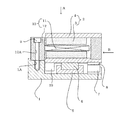
従来、電気部品実装装置、半導体関連装置あるいは工作機械などの各種産業機械に使用されると共に、その直動機構の駆動用に好適なリニアモータは、図3に示すようになっている。なお、図6は従来技術を示すム−ビングマグネット形リニアスライダであって、(a)はその平面図、(b)は(a)のB―B線に沿う正断面図であり、(a)は(b)の矢視Aから透視した図に相当する。
図6において、21は固定ベース、22はマグネットトラック、23は界磁永久磁石、24は界磁ヨーク、25はガイドレール、26はガイドブロック、27はセンサヘッド、28はリニアスケール部、29はストッパ、30は電機子、31は電機子コイル、32は結線基板である。
リニアスライダは、界磁永久磁石23の背面に界磁ヨーク24を設けて、界磁ヨーク24が可動子と磁気回路を兼用している。また、電機子30は、結線基板32上に固着されたスロットレスの電機子コイル31を複数備えた構造を有すると共に、ソリッドの磁性部材でできた固定ベース21上に可動子と磁気的空隙を介して配置されて、固定子を構成している。なお、結線基板32には界磁永久磁石23に対向するように磁極検出を行うための複数の図示しないホール素子を埋め込みようになっている。該ホール素子(不図示)は、電源をONさせた初期の時点で何れかの、ホール素子から対向する界磁磁石の位置を検出して、検出された界磁磁石23の位置に合わせて駆動電流を電機子コイル31に流すための検出信号を出力する(例えば、特許文献1参照)。
この電機子30の両側には、平行するガイドレール25が固定ベース21上に固定され、ガイドレール25上には、該レール上を摺動するガイドブロック26が界磁ヨーク24の両端の下部に固定されている。さらに、可動子の側面には、リニア形のエンコーダを構成する磁気式のリニアスケール28が配設され、このリニアスケール28に対向するように固定ベース21に該リニアスケール28を検出するセンサヘッド27が配設されている。それから、2本のガイドレール25の端部の間には可動子のオーバランを防止するためのストッパ29が設けられている。
このリニアスライダは界磁永久磁石23の磁束が、固定ベース21に鎖交する磁気回路構造になっており、また、電機子コイル31を励磁すると、界磁と電機子とで作られる移動磁界により可動子を、電機子長と可動子長の差であるストローク内で直線移動するようになっている(例えば、特許文献1および2を参照)。
In FIG. 6, 21 is a fixed base, 22 is a magnet track, 23 is a field permanent magnet, 24 is a field yoke, 25 is a guide rail, 26 is a guide block, 27 is a sensor head, 28 is a linear scale section, 29 is A stopper, 30 is an armature, 31 is an armature coil, and 32 is a wiring board.
In the linear slider, a
This linear slider has a magnetic circuit structure in which the magnetic flux of the field
従来のリニアスライダは、先ずリニアモータを構成する電機子と界磁永久磁石が各々の片面側で対向する構造になっているため、この2者間には磁気吸引力が働くことになる。従ってリニアモータを支持するガイドレールおよびガイドブロックはねじりモーメントを軽減するために2列で支持する構造となっている。しかしながら、この構造では、磁気吸引力によりリニアガイドに与圧がかかり、ガイド摩擦を増大させることとなった。また2列のガイドレールの平行度の誤差により、ストローク方向に部分的な摩擦の変化が発生し、推力が一定がとならないため、微小な推力制御ができないという問題があった。
本発明は上記問題を解決するためになされたものであり、リニアモータによる磁気吸引力を無くし、リニアガイドに与圧をかけないようにすると共にリニアガイドをリニアモータ推力中心軸近傍に1本配置し、リニアガイド摩擦を最小化することができる低粘性摩擦ムービングマグネット形リニアスライダ装置およびそれを用いた工作機械を提供することを目的とする。
Since the conventional linear slider has a structure in which the armature constituting the linear motor and the field permanent magnet are opposed to each other on one side, a magnetic attractive force acts between the two. Therefore, the guide rail and the guide block that support the linear motor have a structure of supporting in two rows in order to reduce the torsional moment. However, in this structure, a pressure is applied to the linear guide due to the magnetic attractive force, and the guide friction is increased. In addition, there is a problem that a minute thrust control cannot be performed because a partial frictional change occurs in the stroke direction due to an error in the parallelism of the two rows of guide rails and the thrust is not constant.
The present invention has been made to solve the above-described problem, and eliminates the magnetic attraction force by the linear motor, prevents the linear guide from being pressurized, and arranges one linear guide near the central axis of the linear motor thrust. An object of the present invention is to provide a low-viscosity friction moving magnet type linear slider device capable of minimizing linear guide friction and a machine tool using the same.
上記問題を解決するため、本発明は、次のように構成したものである。
請求項1のムービングマグネット形リニアスライダに係る発明は、固定ベース上に平行に対向配置されると共に、可動子を構成する界磁と固定子を構成する電機子より成るリニアモータと、前記リニアモータの可動子を案内支持するガイドレールとガイドブロックからなるリニアガイドと、前記可動子と前記固定ベースの相対位置を検出するための検出手段と、を備え、前記移動体を前記固定ベースに対して前記ガイドレール上の長手方向に沿って往復動させたムービングマグネット形リニアスライダにおいて、前記リニアモータの界磁は、前記ガイドブロック上に設けられると共に、略U字状の断面形状を有し、かつ、その開口部が水平方向を向くように配設してなる磁性体ヨークと、前記磁性体ヨークの内側対向面の長手方向に沿って極性が交互に異なる磁極が並設され、且つ、互いに対向する前記磁極の極性が反対の極性となるように設けた一対の界磁用永久磁石とよりなるマグネットトラックで構成され、前記リニアモータの電機子は、前記固定ベースの一方の側面上に鉛直方向に取付けた電機子ホルダと、前記電機子ホルダと直交するように設けられると共に、前記一対の界磁用永久磁石の内側に磁気的空隙を介して対向配置させた平板状のコアレス形の電機子コイルとより構成され、前記検出手段は、前記磁性体ヨークの開口部と反対側の底部の下面に設けてなるリニアスケールと、前記電機子ホルダを配設した固定ベースと反対側の側面上に前記リニアスケールに対向するように取付けたセンサヘッドより構成されていることを特徴としている。
また、請求項2の発明は、請求項1記載のムービングマグネット形リニアスライダにおいて、前記マグネットトラックのストローク方向の長さLmgを、前記電機子のストローク方向の長さLaより長くし、該ストローク方向の長さの差LmgーLaをリニアスライダの有効ストロークとすると共に、前記電機子に磁極検出器を内蔵し、該磁極検出器によりリニアスライダの初期磁極を検出するようにしたことを特徴としている。
また、請求項3の発明は、請求項1記載のムービングマグネット形リニアスライダにおいて、前記マグネットトラックのストローク方向の長さLmgを、前記電機子のストローク方向の長さLaより短くし、該ストローク方向の長さの差LaーLmgをリニアスライダの有効ストロークとしたことを特徴としている。
請求項4の発明は、請求項1記載のムービングマグネット形リニアスライダにおいて、前記マグネットトラックのストローク方向の長さLmgを、前記電機子のストローク方向の長さLaより長くし、該ストローク方向の長さの差LmgーLaをリニアスライダの有効ストロークとするものであり、前記電機子のモータリード側と反対側の端部に該電機子と別体になるように磁極検出器を配置固定し、前記マグネットトラックがストローク端に移動した場合であっても常時磁極検出ができるようにしたことを特徴としている。
請求項5の発明は、請求項1〜4までの何れか1項に記載のムービングマグネット形リニアスライダにおいて、前記マグネットトラックの底部に、前記固定ベースと対向するように可動子の重量とバランスさせるための重力補償用ばねを設けたことを特徴としている。
In order to solve the above problems, the present invention is configured as follows.
A moving magnet type linear slider according to a first aspect of the present invention includes a linear motor that is disposed in parallel on a fixed base and includes a field that constitutes a mover and an armature that constitutes a stator, and the linear motor A linear guide comprising a guide rail and a guide block for guiding and supporting the movable element, and detection means for detecting a relative position between the movable element and the fixed base, and the movable body with respect to the fixed base In the moving magnet type linear slider reciprocated along the longitudinal direction on the guide rail, the magnetic field of the linear motor is provided on the guide block and has a substantially U-shaped cross-sectional shape, and A magnetic yoke arranged so that the opening thereof faces in the horizontal direction, and a pole along the longitudinal direction of the inner facing surface of the magnetic yoke Are composed of a magnet track composed of a pair of field permanent magnets arranged such that different magnetic poles are alternately arranged in parallel and the polarities of the opposing magnetic poles are opposite to each other. The child is provided on the one side surface of the fixed base in the vertical direction, and is provided so as to be orthogonal to the armature holder, and a magnetic gap is provided inside the pair of field permanent magnets. And a linear scale formed on a lower surface of the bottom portion opposite to the opening of the magnetic yoke, and the armature. It is characterized by comprising a sensor head mounted on the side surface opposite to the fixed base on which the holder is disposed so as to face the linear scale.
Further, the invention of
Further, the invention of
A fourth aspect of the present invention, in the moving magnet type linear slider according to
According to a fifth aspect of the present invention, in the moving magnet type linear slider according to any one of the first to fourth aspects, the bottom of the magnet track is balanced with the weight of the mover so as to face the fixed base. For this purpose, a gravity compensation spring is provided.
請求項6の発明は、請求項1〜請求項5の何れか1項に記載のムービングマグネット形リニアスライダを直動機構の駆動源として用いた工作機械としたことを特徴としている。 The invention of
請求項1に記載の発明によると、リニアモータによる磁気吸引力を無くし、リニアガイドに与圧をかけないようにすると共にリニアガイドの配置がリニアモータ推力中心軸近傍の1箇所ですみ、リニアガイド摩擦を最小することができる。その結果、リニアスライダの微小推力制御を向上することができる。
また、請求項3に記載の発明によると、コアレス電機子長よりマグネットトラックを短くすることで固定ベース全長範囲内で駆動ストロークを確保することができ、リニアスライダサイズをコンパクトにできる。
請求項2、4に記載の発明によると、請求項3の構成とは逆にコアレス電機子長よりマグネットトラックを長くすることで、可動子がストローク長を移動した場合であっても、磁極検出器により常時初期磁極検出が可能になることから、請求項3で必要であった、ソフトウェアによる磁極検出が電源投入に不要とすることができる。
請求項5に記載の発明によると、マグネットトラックの底部に可動子の重量とバランスさせるための重力補償用ばねを設けることで、コンパクトで且つ緻密な微小推力力制御を可能にできる。
According to the first aspect of the present invention, the magnetic attraction force by the linear motor is eliminated, no pressure is applied to the linear guide, and the linear guide is disposed at one location near the central axis of the linear motor thrust. Friction can be minimized. As a result, the fine thrust control of the linear slider can be improved.
According to the invention described in
According to the second and fourth aspects of the invention, in contrast to the configuration of the third aspect, the magnet track is made longer than the coreless armature length, so that the magnetic pole detection is performed even when the mover moves the stroke length. Since the initial magnetic pole detection is always possible by the detector, the magnetic pole detection by software, which is necessary in the third aspect, can be made unnecessary for turning on the power.
According to the fifth aspect of the present invention, by providing the gravity compensation spring for balancing the weight of the mover at the bottom of the magnet track, it is possible to control a compact and precise minute thrust force.
請求項6に記載の発明によると、請求項1〜請求項5の何れか1項に記載のムービングマグネット形リニアスライダの効果を有する工作機械を提供することができる。 According to invention of
以下、本発明の実施の形態について図を参照して説明する。 Hereinafter, embodiments of the present invention will be described with reference to the drawings.
図1は本発明の第1実施例〜第3実施例に共通なム−ビングマグネット形リニアスライダの正断面図、図2は本発明の第1実施例を示すム−ビングマグネット形リニアスライダであって、(a)は図1の矢視A方向から透視した平面図、(b)は図1の矢視B方向から透視した側面図に相当するものである。
本発明の特徴は以下のとおりである。
図において、1は固定ベース、1Aは固定ベース1に設けた雌ねじ部,2はマグネットトラック、3は界磁永久磁石、4は磁性体ヨーク、4Aは磁性体ヨーク4に設けた雌ねじ部、5はリニアガイドのガイドレール、6はガイドブロック、7はセンサヘッド、8はリニアスケール、9はボルト、10は電機子、11は電機子コイル、12は電機子ホルダ、12Aは電機子ホルダ12に設けた貫通孔、13はストッパ、14は押し当て部、15はセンサホルダ、16はモータリード、17は磁極検出器リード、18はリニアスケールリード、19は重力補償用ばねである。
本発明が従来技術と異なる点は、ムービングマグネット形リニアスライダは、リニアモータの界磁は、ガイドブロック6上に設けられると共に、略U字状の断面形状を有し、かつ、その開口部が水平方向を向くように配設してなる磁性体ヨーク4と、磁性体ヨークの内側対向面の長手方向に沿って極性が交互に異なる磁極が並設され、且つ、互いに対向する磁極の極性が反対の極性となるように設けた一対の界磁用永久磁石3とよりなるマグネットトラック2で構成され、リニアモータの電機子は、固定ベース1の一方の側面上に鉛直方向に取付けた電機子ホルダ12と、電機子ホルダ12と直交するように設けられると共に、一対の界磁用永久磁石3の内側に磁気的空隙を介して対向配置させた平板状のコアレス形の電機子コイル11とより構成されており、吸引力相殺形構造となっている点である、
また、検出手段は、磁性体ヨーク4の開口部と反対側の底部の下面に設けてなるリニアスケール8と、電機子ホルダ12を配設した固定ベース1と反対側の側面上にリニアスケール8に対向するように取付けたセンサヘッド7より構成されたものとなっている。
また、マグネットトラック2のストローク方向の長さLmgを、電機子10のストローク方向の長さLaより長くし、該ストローク方向の長さの差LmgーLaをリニアスライダの有効ストロークとすると共に、電機子10に図示しない磁極検出器を内蔵し、該磁極検出器(不図示)によりリニアスライダの初期磁極を検出するようにしたものとなっている。
また、マグネットトラック2の底部に、固定ベース1と対向するように可動子の重量とバランスさせるための重力補償用ばね19を設けたものとなっている。
FIG. 1 is a front sectional view of a moving magnet type linear slider common to the first to third embodiments of the present invention, and FIG. 2 is a moving magnet type linear slider showing the first embodiment of the present invention. 1A is a plan view seen through from the direction of arrow A in FIG. 1, and FIG. 1B corresponds to a side view seen through from the direction of arrow B in FIG.
The features of the present invention are as follows.
In the figure, 1 is a fixed base, 1A is a female screw portion provided on the
The present invention is different from the prior art in that the moving magnet type linear slider has a substantially U-shaped cross-sectional shape with the magnetic field of the linear motor provided on the
The detecting means includes a
Further, the length L mg of the stroke direction of the
Further, a
次に、動作について説明する。
図1、2に示すように、リニアモータの電機子に図示しない外部電源から通電すると、テーブルを固定ベースに対してガイドレール上の長手方向に沿って往復動するが、その際、移動体であるマグネットトラック2側に設けたリニアスケール8に対して固定ベース1側に設けたセンサヘッド7により、移動体と固定ベースの相対位置を検出する。
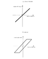
ここで、図3は本実施例によるムービングマグネット形リニアスライダの動作を示す推力特性図である。図3に示すように、(a)の本発明は(b)の従来技術に対して、電流に対する推力特性にヒステリシス性が無くなっており、リニアスライダの微小推力制御を可能にすることができる。
Next, the operation will be described.
As shown in FIGS. 1 and 2, when the armature of the linear motor is energized from an external power source (not shown), the table reciprocates along the longitudinal direction on the guide rail with respect to the fixed base. The relative position between the moving body and the fixed base is detected by the
FIG. 3 is a thrust characteristic diagram showing the operation of the moving magnet type linear slider according to this embodiment. As shown in FIG. 3, the present invention of (a) has no hysteresis property in the thrust characteristics with respect to the current as compared with the prior art of (b), and can control the fine thrust of the linear slider.
したがって、本実施例は上記構成のごとく、リニアモータの界磁と電機子の配置を吸引力相殺構造としたので、リニアモータによる磁気吸引力を無くし、リニアガイドに与圧をかけないようにすると共にリニアガイドの配置がリニアモータ推力中心軸近傍の1箇所ですみ、リニアガイド摩擦を最小することができる。その結果、リニアスライダの微小推力制御を向上することができる。
また、本実施例のリニアスライダは、コアレス電機子長よりマグネットトラックの長さを長くし、電機子に磁極検出器を内蔵した構成にしたので、その長さの差がリニアスライダの有効ストロークとする構造となると共に、電機子に内蔵した磁極検出器により容易に初期磁極検出を行うことができる。
また、マグネットトラック2の底部に、固定ベース1と対向するように可動子の重量とバランスさせるための重力補償用ばね19を設けたので、コンパクトで且つ緻密な微小推力力制御を可能にしている。
Accordingly, in this embodiment, as in the above configuration, the arrangement of the magnetic field and armature of the linear motor has an attractive force canceling structure, so the magnetic attractive force by the linear motor is eliminated and no pressure is applied to the linear guide. At the same time, the arrangement of the linear guide is only one place near the central axis of the linear motor thrust, and the linear guide friction can be minimized. As a result, the fine thrust control of the linear slider can be improved.
In addition, the linear slider of this embodiment has a configuration in which the length of the magnet track is made longer than the coreless armature length and the armature has a built-in magnetic pole detector, so that the difference in length is the effective stroke of the linear slider. In addition, the magnetic pole detector built in the armature can easily detect the initial magnetic pole.
Further, since a
図4は本発明の第2実施例を示すム−ビングマグネット形リニアスライダであって、(a)は図1の矢視A方向から透視した平面図、(b)は図1の矢視B方向から透視した側面図に相当するものである。
第2実施例が第1実施例と異なる点は、マグネットトラック2のストローク方向の長さLmgを、電機子10のストローク方向の長さLaより短くし、該ストローク方向の長さの差LaーLmgをリニアスライダの有効ストロークとすると共に、リニアスライダの初期磁極検出をソフトウェアにより検出するようにした点である。なお、リニアスライダの初期磁極検出は、電源投入時にソフトウェアによる磁極サーチを行う必要がある。
FIG. 4 is a moving magnet type linear slider showing a second embodiment of the present invention, in which (a) is a plan view seen through from the direction of arrow A in FIG. 1, and (b) is a view from arrow B in FIG. This corresponds to a side view seen through from the direction.
The second embodiment is different from the first embodiment, the length L mg of the stroke direction of the
したがって、本実施例は、コアレス電機子長よりマグネットトラックを短くすることで、その長さの差がリニアスライダの有効ストロークとする構造となることから、固定ベース全長範囲ないで駆動ストロークを確保することができ、リニアスライダサイズを小形化することができる。 Therefore, in this embodiment, by making the magnet track shorter than the coreless armature length, the difference in length becomes the effective stroke of the linear slider, so that the driving stroke is ensured without the total length range of the fixed base. The linear slider size can be reduced.
図5は本発明の第3実施例を示すム−ビングマグネット形リニアスライダであって、(a)は図1の矢視A方向から透視した平面図、(b)は図1の矢視B方向から透視した側面図に相当するものである。
第3実施例が第1実施例と異なる点は、マグネットトラック2のストローク方向の長さLmgを、電機子10のストローク方向の長さLaより長くし、該ストローク方向の長さの差LmgーLaをリニアスライダの有効ストロークとするものであり、電機子10のモータリード側と反対側の端部に該電機子10と別体になるように磁極検出器(磁極検出器ヘッド20)を配置固定し、マグネットトラック2がストローク端に移動した場合であっても常時磁極検出ができるようにした点である。
FIG. 5 is a moving magnet type linear slider showing a third embodiment of the present invention, wherein (a) is a plan view seen through from the direction of arrow A in FIG. 1, and (b) is a view from arrow B in FIG. This corresponds to a side view seen through from the direction.
The third embodiment is different from the first embodiment, the length L mg of the stroke direction of the
したがって、第3実施例のリニアスライダは上記構成にしたので、コアレス電機子長よりマグネットトラックの長さを長くし、電機子の端部の位置に電機子とは別体に磁極検出器を設ける構成にしたので、磁極検出器により可動子がストローク長を移動した場合であっても、常時初期磁極検出が可能になることから、第2実施例で必要であった、ソフトウェアによる磁極検出が電源投入に不要とすることができる。 Therefore, since the linear slider of the third embodiment is configured as described above, the length of the magnet track is made longer than the length of the coreless armature, and a magnetic pole detector is provided separately from the armature at the position of the end of the armature. Since it is configured, even if the mover moves the stroke length by the magnetic pole detector, it becomes possible to always detect the initial magnetic pole. It can be made unnecessary for input.
リニアガイド摩擦を小さく、且つストローク領域で一定にすることによって微小推力制御が可能となるので、先端部の緻密な制御が必要なガラスカッティングマシン等の用途にも適用できる。 Small thrust control is possible by making the linear guide friction small and constant in the stroke region, so it can be applied to applications such as glass cutting machines that require precise control of the tip.
1 固定ベース
1A 雌ねじ部
2 マグネットトラック
3 界磁永久磁石
4 磁性体ヨーク
4A 雌ねじ部
5 リニアガイドのレール
6 ガイドブロック
7 センサヘッド
8 リニアスケール
9 ボルト
10 電機子
11 電機子コイル
12 電機子ホルダ
12A 貫通孔
13 ストッパ
14 押し当て部
15 センサホルダ
16 モータリード
17 磁極検出器リード
18 リニアスケールリード
19 重力補償用ばね
20 磁極検出ヘッド
21 固定ベース
22 マグネットトラック
23 界磁永久磁石
24 界磁ヨーク
25 ガイドレール
26 ガイドブロック
27 センサヘッド
28 リニアスケール部
29 ストッパ
30 電機子
31 電機子コイル
32 結線基板
DESCRIPTION OF
Claims (6)
前記リニアモータの界磁は、前記ガイドブロック上に設けられると共に、略U字状の断面形状を有し、かつ、その開口部が水平方向を向くように配設してなる磁性体ヨークと、前記磁性体ヨークの内側対向面の長手方向に沿って極性が交互に異なる磁極が並設され、且つ、互いに対向する前記磁極の極性が反対の極性となるように設けた一対の界磁用永久磁石とよりなるマグネットトラックで構成され、
前記リニアモータの電機子は、前記固定ベースの一方の側面上に鉛直方向に取付けた電機子ホルダと、前記電機子ホルダと直交するように設けられると共に、前記一対の界磁用永久磁石の内側に磁気的空隙を介して対向配置させた平板状のコアレス形の電機子コイルとより構成され、
前記検出手段は、前記磁性体ヨークの開口部と反対側の底部の下面に設けてなるリニアスケールと、前記電機子ホルダを配設した固定ベースと反対側の側面上に前記リニアスケールに対向するように取付けたセンサヘッドより構成されていることを特徴とするムービングマグネット形リニアスライダ。The linear motor is composed of a magnetic field that constitutes a movable element and an armature that constitutes the stator, and a guide rail and a guide block that guide and support the movable element of the linear motor. A linear guide; and a detecting means for detecting a relative position between the movable element and the fixed base, and the movable body is reciprocated along the longitudinal direction on the guide rail with respect to the fixed base. In moving magnet type linear slider,
The magnetic field of the linear motor is provided on the guide block, has a substantially U-shaped cross-sectional shape, and has a magnetic yoke formed such that its opening is oriented in the horizontal direction, A pair of field permanents provided with magnetic poles having different polarities alternately arranged in parallel along the longitudinal direction of the inner facing surface of the magnetic yoke, and the opposite polarities of the magnetic poles facing each other. It consists of a magnet track consisting of magnets,
The armature of the linear motor is provided so as to be perpendicular to the armature holder mounted on one side surface of the fixed base and perpendicular to the armature holder, and inside the pair of field permanent magnets And a plate-like coreless armature coil disposed opposite to each other via a magnetic gap,
The detecting means faces the linear scale on a side surface opposite to the fixed base on which the armature holder is disposed, and a linear scale provided on the bottom surface of the bottom portion on the opposite side to the opening of the magnetic yoke. A moving magnet type linear slider comprising a sensor head mounted in such a manner.
前記電機子に磁極検出器を内蔵し、該磁極検出器によりリニアスライダの初期磁極を検出するようにしたことを特徴とする請求項1記載のムービングマグネット形リニアスライダ。That the length L mg of the stroke direction of the magnet track, longer than the length L a of the stroke direction of the armature, is of the stroke direction of the difference L mg over L a length effective stroke of the linear slider And
2. The moving magnet type linear slider according to claim 1, wherein a magnetic pole detector is built in the armature, and an initial magnetic pole of the linear slider is detected by the magnetic pole detector.
Priority Applications (1)
| Application Number | Priority Date | Filing Date | Title |
|---|---|---|---|
| JP2006514426A JP4702629B2 (en) | 2004-05-14 | 2005-05-12 | Moving magnet type linear slider and machine tool using the same |
Applications Claiming Priority (4)
| Application Number | Priority Date | Filing Date | Title |
|---|---|---|---|
| JP2004175306 | 2004-05-14 | ||
| JP2004175306 | 2004-06-14 | ||
| PCT/JP2005/008678 WO2005122369A1 (en) | 2004-05-14 | 2005-05-12 | Moving magnet type linear slider |
| JP2006514426A JP4702629B2 (en) | 2004-05-14 | 2005-05-12 | Moving magnet type linear slider and machine tool using the same |
Publications (2)
| Publication Number | Publication Date |
|---|---|
| JPWO2005122369A1 JPWO2005122369A1 (en) | 2008-04-10 |
| JP4702629B2 true JP4702629B2 (en) | 2011-06-15 |
Family
ID=35503422
Family Applications (1)
| Application Number | Title | Priority Date | Filing Date |
|---|---|---|---|
| JP2006514426A Expired - Fee Related JP4702629B2 (en) | 2004-05-14 | 2005-05-12 | Moving magnet type linear slider and machine tool using the same |
Country Status (6)
| Country | Link |
|---|---|
| US (1) | US7659641B2 (en) |
| JP (1) | JP4702629B2 (en) |
| KR (1) | KR101066357B1 (en) |
| CN (1) | CN100553085C (en) |
| TW (1) | TWI362162B (en) |
| WO (1) | WO2005122369A1 (en) |
Families Citing this family (18)
| Publication number | Priority date | Publication date | Assignee | Title |
|---|---|---|---|---|
| DE102006022192B4 (en) * | 2006-05-12 | 2009-08-27 | Rovema - Verpackungsmaschinen Gmbh | Device for welding a film web |
| DE102006022193B4 (en) * | 2006-05-12 | 2009-08-27 | Rovema - Verpackungsmaschinen Gmbh | Vertical tubular bag machine with two linear motors |
| JP5253824B2 (en) * | 2008-01-11 | 2013-07-31 | ヤマハ発動機株式会社 | Linear motor, component mounting device and component inspection device |
| JP5250268B2 (en) * | 2008-01-11 | 2013-07-31 | ヤマハ発動機株式会社 | Parts transfer device |
| JP5250267B2 (en) * | 2008-01-11 | 2013-07-31 | ヤマハ発動機株式会社 | Linear motor and component transfer device |
| JP5598757B2 (en) * | 2010-01-26 | 2014-10-01 | 株式会社安川電機 | Refrigerant cooling linear motor |
| JP5859856B2 (en) | 2012-01-11 | 2016-02-16 | ヤマハ発動機株式会社 | Linear motor and component mounting device |
| US9324523B2 (en) * | 2012-10-18 | 2016-04-26 | Panasonic Intellectual Property Management Co., Ltd. | Power generation device |
| KR101308317B1 (en) * | 2013-03-19 | 2013-10-04 | 장석호 | Electric motor which serves as power generator also using coil plate having devided coil and reciprocating sliding plate having devided magnet |
| CN104259869B (en) * | 2014-05-20 | 2017-03-22 | 大连日佳电子有限公司 | Double-layer double-phase reactive linear precision adjustment sliding table |
| US10471610B2 (en) | 2015-06-16 | 2019-11-12 | Samsung Electronics Co., Ltd. | Robot arm having weight compensation mechanism |
| CN107370331B (en) * | 2016-05-13 | 2019-11-29 | 台达电子工业股份有限公司 | Actuator and linear moving module |
| TWI589100B (en) * | 2016-05-13 | 2017-06-21 | 台達電子工業股份有限公司 | Actuator and linear motion module |
| NL2018266B1 (en) | 2017-01-31 | 2018-08-16 | Ccm Beheer Bv | Planar positioning device |
| CN113647001A (en) * | 2019-04-10 | 2021-11-12 | 雅马哈发动机株式会社 | Linear driving device and head for mounting component |
| KR20210148401A (en) * | 2019-04-29 | 2021-12-07 | 쿨리케 앤드 소파 인더스트리즈, 인코포레이티드 | Linear motor and wire bonding machine including same |
| CN109980891A (en) * | 2019-04-30 | 2019-07-05 | 郑雨 | One Artenkreis rail linear motor |
| CN111564947A (en) * | 2020-05-19 | 2020-08-21 | 广州市昊志机电股份有限公司 | Coreless arc linear motor and driving device |
Citations (3)
| Publication number | Priority date | Publication date | Assignee | Title |
|---|---|---|---|---|
| JPH06253526A (en) * | 1993-03-01 | 1994-09-09 | Sharp Corp | Linear driver |
| JPH08140329A (en) * | 1994-11-07 | 1996-05-31 | Toyota Auto Body Co Ltd | Moving magnet linear motor |
| JP2003172615A (en) * | 2001-12-07 | 2003-06-20 | Hitachi Metals Ltd | Position detection means and relative movement apparatus |
Family Cites Families (5)
| Publication number | Priority date | Publication date | Assignee | Title |
|---|---|---|---|---|
| JP3815750B2 (en) * | 1995-10-09 | 2006-08-30 | キヤノン株式会社 | Stage apparatus, and exposure apparatus and device manufacturing method using the stage apparatus |
| JP4094799B2 (en) * | 2000-06-22 | 2008-06-04 | 日本トムソン株式会社 | Slide device with built-in movable magnet type linear motor |
| JP2004015904A (en) * | 2002-06-06 | 2004-01-15 | Canon Inc | Linear stage, linear positioner and linear spin stand |
| JP2005278280A (en) * | 2004-03-24 | 2005-10-06 | Yaskawa Electric Corp | Moving coil type linear slider |
| JP4521221B2 (en) * | 2004-05-18 | 2010-08-11 | 日本トムソン株式会社 | Slide device with built-in movable magnet type linear motor |
-
2005
- 2005-05-12 WO PCT/JP2005/008678 patent/WO2005122369A1/en active Application Filing
- 2005-05-12 JP JP2006514426A patent/JP4702629B2/en not_active Expired - Fee Related
- 2005-05-12 KR KR1020067022023A patent/KR101066357B1/en not_active IP Right Cessation
- 2005-05-12 CN CNB2005800188077A patent/CN100553085C/en not_active Expired - Fee Related
- 2005-06-08 TW TW094118914A patent/TWI362162B/zh active
-
2006
- 2006-12-12 US US11/637,245 patent/US7659641B2/en not_active Expired - Fee Related
Patent Citations (3)
| Publication number | Priority date | Publication date | Assignee | Title |
|---|---|---|---|---|
| JPH06253526A (en) * | 1993-03-01 | 1994-09-09 | Sharp Corp | Linear driver |
| JPH08140329A (en) * | 1994-11-07 | 1996-05-31 | Toyota Auto Body Co Ltd | Moving magnet linear motor |
| JP2003172615A (en) * | 2001-12-07 | 2003-06-20 | Hitachi Metals Ltd | Position detection means and relative movement apparatus |
Also Published As
| Publication number | Publication date |
|---|---|
| JPWO2005122369A1 (en) | 2008-04-10 |
| CN100553085C (en) | 2009-10-21 |
| CN1965460A (en) | 2007-05-16 |
| US20070096567A1 (en) | 2007-05-03 |
| KR20070021184A (en) | 2007-02-22 |
| WO2005122369A1 (en) | 2005-12-22 |
| TWI362162B (en) | 2012-04-11 |
| US7659641B2 (en) | 2010-02-09 |
| KR101066357B1 (en) | 2011-09-20 |
Similar Documents
| Publication | Publication Date | Title |
|---|---|---|
| JP4702629B2 (en) | Moving magnet type linear slider and machine tool using the same | |
| JP4094799B2 (en) | Slide device with built-in movable magnet type linear motor | |
| US6348746B1 (en) | Slider unit with built-in moving-coil linear motor | |
| JP4104810B2 (en) | Slide device with built-in movable magnet type linear motor | |
| JP5006579B2 (en) | Slide device with built-in movable magnet type linear motor | |
| US7268336B2 (en) | Image detecting module | |
| JP2007325389A5 (en) | ||
| JP5106833B2 (en) | Linear motor and single-axis actuator | |
| US7493029B2 (en) | Camera module | |
| JP2002064968A (en) | Slider with built-in moving coil linear motor | |
| JP2006320035A (en) | Linear motor | |
| JP4684679B2 (en) | Slide device with built-in linear motor | |
| JP2016036228A (en) | Table device, positioning device, and precision machine | |
| KR100462388B1 (en) | A Stage Device Of X-Y Precision Drive Using VCM | |
| US7486881B2 (en) | Image detection module | |
| JP2005278280A (en) | Moving coil type linear slider | |
| JP2004312956A (en) | Linear actuator | |
| JP5306558B2 (en) | Linear motor | |
| KR101370230B1 (en) | Linear motor | |
| JP4522674B2 (en) | Small slide device | |
| JP2002096233A (en) | Linear slider | |
| JP2016036227A (en) | Table device, positioning device, and precision machine | |
| JP5669446B2 (en) | Driving mechanism of moving body | |
| JP2016140191A (en) | Slide device for vertical shaft with built-in movable-coil type linear motor | |
| JPWO2007013289A1 (en) | Linear motor |
Legal Events
| Date | Code | Title | Description |
|---|---|---|---|
| A521 | Request for written amendment filed |
Free format text: JAPANESE INTERMEDIATE CODE: A523 Effective date: 20080328 |
|
| A621 | Written request for application examination |
Free format text: JAPANESE INTERMEDIATE CODE: A621 Effective date: 20080328 |
|
| TRDD | Decision of grant or rejection written | ||
| A01 | Written decision to grant a patent or to grant a registration (utility model) |
Free format text: JAPANESE INTERMEDIATE CODE: A01 Effective date: 20110210 |
|
| A61 | First payment of annual fees (during grant procedure) |
Free format text: JAPANESE INTERMEDIATE CODE: A61 Effective date: 20110223 |
|
| R150 | Certificate of patent or registration of utility model |
Ref document number: 4702629 Country of ref document: JP Free format text: JAPANESE INTERMEDIATE CODE: R150 |
|
| FPAY | Renewal fee payment (event date is renewal date of database) |
Free format text: PAYMENT UNTIL: 20150318 Year of fee payment: 4 |
|
| LAPS | Cancellation because of no payment of annual fees |