JP4700245B2 - Sampling / dispensing instrument with plunger and housing cured on plunger - Google Patents
Sampling / dispensing instrument with plunger and housing cured on plunger Download PDFInfo
- Publication number
- JP4700245B2 JP4700245B2 JP2001516665A JP2001516665A JP4700245B2 JP 4700245 B2 JP4700245 B2 JP 4700245B2 JP 2001516665 A JP2001516665 A JP 2001516665A JP 2001516665 A JP2001516665 A JP 2001516665A JP 4700245 B2 JP4700245 B2 JP 4700245B2
- Authority
- JP
- Japan
- Prior art keywords
- plunger
- housing
- instrument
- molding
- central plunger
- Prior art date
- Legal status (The legal status is an assumption and is not a legal conclusion. Google has not performed a legal analysis and makes no representation as to the accuracy of the status listed.)
- Expired - Lifetime
Links
Images


Classifications
-
- B—PERFORMING OPERATIONS; TRANSPORTING
- B01—PHYSICAL OR CHEMICAL PROCESSES OR APPARATUS IN GENERAL
- B01L—CHEMICAL OR PHYSICAL LABORATORY APPARATUS FOR GENERAL USE
- B01L3/00—Containers or dishes for laboratory use, e.g. laboratory glassware; Droppers
- B01L3/02—Burettes; Pipettes
- B01L3/021—Pipettes, i.e. with only one conduit for withdrawing and redistributing liquids
- B01L3/0217—Pipettes, i.e. with only one conduit for withdrawing and redistributing liquids of the plunger pump type
-
- G—PHYSICS
- G01—MEASURING; TESTING
- G01N—INVESTIGATING OR ANALYSING MATERIALS BY DETERMINING THEIR CHEMICAL OR PHYSICAL PROPERTIES
- G01N35/00—Automatic analysis not limited to methods or materials provided for in any single one of groups G01N1/00 - G01N33/00; Handling materials therefor
- G01N35/02—Automatic analysis not limited to methods or materials provided for in any single one of groups G01N1/00 - G01N33/00; Handling materials therefor using a plurality of sample containers moved by a conveyor system past one or more treatment or analysis stations
- G01N35/04—Details of the conveyor system
- G01N2035/0401—Sample carriers, cuvettes or reaction vessels
- G01N2035/0406—Individual bottles or tubes
- G01N2035/0408—Individual bottles or tubes connected in a flexible chain
-
- G—PHYSICS
- G01—MEASURING; TESTING
- G01N—INVESTIGATING OR ANALYSING MATERIALS BY DETERMINING THEIR CHEMICAL OR PHYSICAL PROPERTIES
- G01N35/00—Automatic analysis not limited to methods or materials provided for in any single one of groups G01N1/00 - G01N33/00; Handling materials therefor
- G01N35/10—Devices for transferring samples or any liquids to, in, or from, the analysis apparatus, e.g. suction devices, injection devices
- G01N35/1065—Multiple transfer devices
-
- Y—GENERAL TAGGING OF NEW TECHNOLOGICAL DEVELOPMENTS; GENERAL TAGGING OF CROSS-SECTIONAL TECHNOLOGIES SPANNING OVER SEVERAL SECTIONS OF THE IPC; TECHNICAL SUBJECTS COVERED BY FORMER USPC CROSS-REFERENCE ART COLLECTIONS [XRACs] AND DIGESTS
- Y10—TECHNICAL SUBJECTS COVERED BY FORMER USPC
- Y10T—TECHNICAL SUBJECTS COVERED BY FORMER US CLASSIFICATION
- Y10T436/00—Chemistry: analytical and immunological testing
- Y10T436/25—Chemistry: analytical and immunological testing including sample preparation
- Y10T436/2575—Volumetric liquid transfer
Landscapes
- Health & Medical Sciences (AREA)
- Clinical Laboratory Science (AREA)
- Chemical & Material Sciences (AREA)
- Chemical Kinetics & Catalysis (AREA)
- Devices For Use In Laboratory Experiments (AREA)
- Sampling And Sample Adjustment (AREA)
- Automatic Analysis And Handling Materials Therefor (AREA)
- Feeding, Discharge, Calcimining, Fusing, And Gas-Generation Devices (AREA)
- Physical Or Chemical Processes And Apparatus (AREA)
- Apparatus Associated With Microorganisms And Enzymes (AREA)
- Laminated Bodies (AREA)
- Analysing Materials By The Use Of Radiation (AREA)
- Application Of Or Painting With Fluid Materials (AREA)
- Processing And Handling Of Plastics And Other Materials For Molding In General (AREA)
Abstract
Description
【0001】
(技術分野)
本発明は、確実送出形(positive displacement type)物質サンプラ/ディスペンサに関する。
【0002】
(背景技術)
このようなディスペンサ(分配器)の一例として、一般的に使用されているプランジャ形ピペットがある。ピペットは、一般に、プランジャが配置される中央ボアを備えた円筒状の外側ハウジングを有している。プランジャは、ボア内で摺動して、流体または粒状物質等の物質をハウジングの一端のオリフィスから分配でき、或いは、反対方向に摺動する場合には、流体または粒状物質をハウジング内に吸引する。このようなディスペンサは、高精度で物質を吸引しかつ分配できる特別な長所を有している。しかしながら、現在使用されている器具は、それぞれに付随する問題を有している。
【0003】
第1に、平行なハウジングボアを有する器具を作ることは極めて困難であり、このことは、吸引されまたは分配される物質の体積間の関係がプランジャの変位量に対して線形関係にないことを意味する。このことは、小体積器具について特に云えることである。また、プランジャとボア壁との間に締り嵌めが確保される精度レベルにボアを作ることは極めて困難であり、このことは、流体がプランジャの縁部の周囲を通ることができ、従ってサンプリング(試料採取)/ディスペンシング(分配)精度の低下および漏洩の危険をもたらすことを意味する。
【0004】
一般にピストンは、シーリングのための締り嵌めを形成するように、ボアに対して僅かに過大の寸法を有している。これに適応しかつボアに抜け勾配を付すことができるようにするため、ピストンまたはボアのいずれかが柔軟材料で作られる。このような例として、剛性ポリスチレンボアとゴムピストンエンドとを備えた医療用注射器、または剛性ポリプロピレンピストンと柔軟薄壁ボアとを備えた医療用注射器がある。他のシーリング構造として、ピストンの端部にリップシールを設けたものがある。これらの構造は多くの欠点、すなわち、耐薬品性が要求される場合には一般に柔軟材料を使用できないこと、直径の小さいボア射出成形は困難性が高いため、ナノリットル(nl)範囲の正確な分配が可能な器具は不可能であること、抜け勾配および慣用成形技術を必要とすることがピペットの実用長さ、従って動的範囲を制限すること、およびリップシールを備えたピストンの製造は、直径が1mm以下の場合には困難性が高いこと等の欠点を有している。
【0005】
かくして、この構成方法は、長ボア、高精度、低コストおよびサブマイクロリットル器具には適していない。
【0006】
このような器具に付随する他の問題は、これらの器具は自動的な取扱いが困難であること、製造コストが嵩むこと、プランジャおよびハウジングを作る材料を、これらの両部品用の成形工具を変更することなく変えることがしばしば困難なことである。
【0007】
(発明の開示)
本発明の第1態様によれば、第1材料で形成された中央プランジャと、
第2材料で形成されたプランジャハウジングとを有し、該プランジャハウジングは、プランジャがハウジング内で摺動して物質をハウジング内に吸引できるように、プランジャの表面上で第2材料を成形しかつ硬化することにより形成されていることを特徴とする確実送出形物質サンプリング/ディスペンシング器具が提供される。
【0008】
第1材料は、金属、プラスチック、セラミックまたは他の適当な材料で形成できる。プランジャは、均一な直径を確保できるように、引抜きワイヤまたは押出し金属で形成される。ハウジングは、射出成形、融着、同時押出し、鋳造およびディップコーティング等によりプランジャ上に成形される。
【0009】
材料は、ピストンの材料の方がボアの材料よりも剛性が高く、および/または熱膨張係数が小さいものを選択するのが好ましい。溶融プラスチックを使用して金属ワイヤの周囲にボアを形成する場合のように、製造中に熱が加えられる場合には、ボアは、器具が冷却されるにつれて、ピストンの周囲を徐々に締め付け、良好なシールを形成する。成形中に、ピストンがボアの材料の温度よりも低温に維持されるならば、ピストンの膨張量をボアに比べてかなり小さく維持できるため、シーリングが一層改善される。ピストンは能動的に冷却するか、ボアの材料よりも高い熱伝導率または比熱を有する材料を使用することができる。
【0010】
自動化された取扱いを容易にするため、器具は、その製造中に、他の器具が取り付けられる可撓性ストリップ装置の他の裏当て材料に取り付けられるか、組み付けられる。
【0011】
可撓性ストリップには、ピペットを駆動しかつ整合させるためのスプロケット孔を設けることができる。
【0012】
或いは、器具は、単一の別個のピペットとして製造することもできる。ピペットは、慣用の確実送出形ピペットと同様に、ピペットのプランジャハウジングおよびプランジャの両方をグリップしかつボア内でプランジャを移動させることにより操作される。この操作は、手動によるか、自動装置を用いて行なうこともできる。器具は単一で使用するか、裏当てストリップの使用の如何を問わず多数で使用することができる。
【0013】
ストリップの材料は、器具のハウジングの一部または全部を形成することができる。
【0014】
ハウジングは、使用前に器具が汚染されることを防止するため、使用前に除去できる脆弱先端部が器具の一端に設けられるように成形できる。
【0015】
或いは、器具は、熱シール可能な先端部をもつように形成でき、これにより、器具に物質を充填し、器具の先端部をシーリングすることにより物質を所定箇所に密封することができる。
【0016】
器具は、「チップベース形(chip-based)」分析器具、化学的合成器およびセンサ等の流体器具内に組み込んで、例えば毛管、弁およびポンプを構成することができる。
【0017】
器具は、異なる軸線上に配置された複数のプランジャを備え、各プランジャがハウジングの異なる領域内で摺動し、ハウジングの異なる領域が1つの孔に隣接する中央の共通コアで結合されるように構成できる。
【0018】
プランジャの周囲にハウジングを形成することにより、器具の製造コストをかなり低減できる。また、このような器具は、プランジャとハウジングとの間に高度の有効シールが形成され、非常に少量のサンプルのディスペンシングおよびサンプリングを行なうように構成されている場合でも均一な円筒壁を確保できる。
【0019】
器具は、吸引ワイヤの周囲にボアを成形することにより形成され、これにより、全長に亘って完全に円筒状のボアを備えたピペットが製造される。使用時に、吸引ワイヤが器具の先端部から突出して、貯蔵容器のシールを穿刺するか、自動レベル検出用の超音波プローブまたは電極として機能する。相手電極として機能する第2導体をピストンと並列に配置することができる。
【0020】
ボアは、先端部が研摩されて尖っているピストンの周囲に形成することができる。これにより、器具の先端部のボアより小径の孔を形成でき、これは、より大きいボアの器具内に液体を保持するときに重要である。
【0021】
(発明を実施するための最良の形態)
以下、添付図面を参照して、本発明の一例を説明する。
【0022】
図1に示すように、従来技術の確実送出形ピペットは外側ハウジング1を有し、該ハウジング1内にはプランジャ2が摺動可能に保持されている。プランジャ2は、孔3を介してハウジング1内にサンプル(試料)を吸引するか、ハウジング1から試料を排出すべく移動される。プランジャ2はヘッド4を有し、該ヘッド4は、比較的硬くて、かつハウジング1内でのプランジャ2の位置に対してハウジング直径の変化を充分に補償できる弾性を有する材料で形成されている。製造の困難性、不正確さおよび漏洩に関するこの器具の欠点は、前述の通りである。
【0023】
図2は、製造中の本発明による器具10を示す側断面図である。器具10は、中央プランジャ12(この例では、引抜き金属で形成されている)と、外側ハウジング11とを有している。外側ハウジング11は、プランジャ12上に成形される。外側ハウジング11の形成に熱可塑性プラスチック(例えば、ポリエチレンまたはポリプロピレン)が使用される場合には、プランジャ12は、ハウジング11より高い融点と、好ましくは小さい熱膨張係数をもつ材料で形成すべきである。プランジャは、例えば、金属、ガラス、プラスチックまたはセラミックで作ることができる。ハウジングは、熱硬化性材料(例えば、シリコーンゴムまたはポリウレタン樹脂)、または溶媒中に溶解された熱可塑性プラスチック(例えば、溶媒中のポリカーボネートまたはポリ塩化ビニル)で形成することもでき、この場合には、プランジャ材料は、ハウジング材料よりも高い融点をもつ必要はない。硬化時に収縮する熱硬化性材料を使用するのが好ましい。
【0024】
ハウジング11は、射出成形、押出し成形、または良く知られた他の任意の鋳造技術、超音波技術、融着技術、ディップコーティング技術、同時押出し技術、粉末コーティング技術、熱成形技術、スプレー成形技術により成形できる。ハウジング11が冷却されかつ硬化されたならば、器具は所定長さに切断される。使用に際し、プランジャ12がハウジング11内に引っ込められると、孔13と、内部コア14(使用時に、このコア14内にサンプルが吸引される)とが残される。内部コア14は、プランジャ12の外表面に一致する均一円筒である。また、内部コア14は、使用される成形技術のため、プランジャ12と極めて緊密に係合する。
【0025】
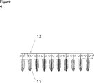
図4は、本発明の器具10を、取扱いを容易にする1つ以上の可撓性ストリップ15に取り付ける方法を示す。より詳しくは、このような構造は自動機械により非常に容易に取り扱われる。実際に、器具10は極めて低コストで製造できるため、使い捨て物品として取り扱うことができる。
【0026】
器具10の構造は変更できる。第1に、ハウジング11をプランジャ12の端部上に形成し、かつプランジャ端部の汚染を防止するため、器具使用の直前にパチンと切断できる脆弱領域を備えた構造に構成できる。また、孔13に隣接して、器具10に熱シール可能領域を設け、物質が器具10のコア14内に配置されかつコア14内にシールされるように構成できる。これにより、ひとたび端部を切除すると、内容物を損失することなく内容物を定量しかつ供給できる密封器具が提供される。
【0027】
図5には、更に別の構成が示されている。この実施形態では、複数のプランジャ12が、これらの上に形成された外側ハウジング11を有している。全てのプランジャ12は、共通のコア14および先端部13にアクセスできる。ピストンを引き出すことにより、器具内に毛管経路が形成される。液体は、ピストンを移動させることにより、システムを通って非常に正確に吸引されかつ移動される。毛管が交差する箇所で、ピストンは、流れを停止させまたは調整する能動弁として操作される。器具には、内容物を検出器により分析できるようにする覗き窓(図示せず)を組み込むことができる。このような構造により、サンプリング/ディスペンシング精度が高くかつ漏洩が極めて少ない、極めてコスト有効性に優れた多サンプル吸引および分配構造が提供される。
【0028】
この構造形式は、図示の簡単な例に限定されるものではない。本発明の方法を使用して、「チップベース形」分析器具、化学的合成器およびセンサ等の3次元流体器具に多数のポンプ、毛管および弁を組み込むことができる。
【0029】
特に優れた長所を有する3つの例について、以下に説明する。
【0030】
例1
図4には、本発明に従って構成された器具が示されている。内径0.43mmおよび外径0.66mmの高密度ポリエチレン(HDPE)チューブ内に、直径0.40mmの硬質引抜き/磨きステンレス鋼ワイヤ(英国標準規格2056 302S26)が挿入される。このチューブは、厚さ0.175mmのポリプロピレンフィルムで作られた幅30mmのテープを横切って置かれる。次に、ワイヤインサートを備えたチューブが、プラスチックチューブの長さに沿って半円筒状超音波融着ホーンを用いて、裏当てテープ上に融着される。これにより、チューブ材料がワイヤの周囲に流れるように、プラスチックチューブが加圧されかつ溶融される。これにより、ワイヤとチューブ素材との間の0.03mmの間隙がなくなる。かくしてピペットが形成され、かつ同時に1作業で裏当てフィルムに融着される。連続ステップアンドリピート法により多数のピペットを形成できる。
【0031】
次に、テープ打ち抜くことによりチューブおよびワイヤを切断し、1作業でピペット形状およびスプロケット孔16を形成する。
裏当てテープが切断され、細いピペットが形成される。
【0032】
ピペットは、裏当てテープから切断して単独で使用することができ、或いは裏当てテープ上に保持して、多数の形態で使用できる。裏当てテープのピッチは、標準規格96、384、1536−凹状微滴定プレート(well microtitre plates)のピッチに一致するように、2.25mmの倍数(この場合には、4.5mm)となるように選択された。
【0033】
吸引/分配ヘッドは、裏当てテープまたはバレルおよびピストンを独立してグリップし、使用者が手動でまたは自動制御によりピストンを上下させて、定量を行なうように構成できる(図示せず)。筆記用インキの100、200、300、400および500nlサンプルを吸引しかつ該サンプルを滴下により受容器内に分配することにより、プロトタイプ器具を用いて体積精度試験を行なった。結果は重力滴定により測定され、図7に示されている。図7は、本発明に従って最適化されていない器具でも、100nlほど小さいサンプルの正確な吸引および分配が可能であることを示している。
【0034】
貯蔵器具としての性能を試験すべく、上記構造のプロトタイプ器具の試験を行なった。各器具内に100nlの空気を吸引し、その後に100nlの水およびを吸引し、最後に100nlの空気を吸引した。開端部をもつ器具およびシール端部をもつ器具が試験された。端部は、ホットワックスまたはホット溶融接着剤中に浸漬するか、端部を熱融着することによりシールされた。サンプルは、室温、−20℃および−74℃の温度で30日間貯蔵された。開端形ピペットは、室温で急速に重量が低下し、6時間で全てのサンプルが喪失された。他の全てのサンプルは、試験中にいかなる重量の損失も検出されなかった。
【0035】
貯蔵についてのこのアプローチの長所は、貯蔵される全ての材料を回収できること、および貯蔵されたサンプルの定量および分配にもこの貯蔵器具を使用できることである。
【0036】
図8は、例1の方法により作られたピペットの断面を示す顕微鏡写真である。円形から外れた歪みは、切断に使用した切刃により生じたものである。ワイヤプランジャの再挿入時に、器具は円形断面を呈する。
【0037】
上記方法により、裏当てテープにポリエチレン被覆PETフィルムを用いた他の器具を製造した。PET層は、機械的供給に適した剛性の高い裏当てテープを形成する。
【0038】
例2
金型製造用シリコーンゴム内に、直径0.5mmのステンレス鋼ワイヤをインサート成形することにより、本発明による器具を製造した。長さ100mm、高さ20mmおよび厚さ3mmの空隙が形成されるように、厚さ1mmの2枚のガラスシートの間にサンドイッチされた厚さ3mmの3枚のアルミニウムシートから金型を製造した。この組立体をばねクリップを用いて一体に保持し、空隙の頂部を開いて樹脂を充填できるようにした。この金型の上方からステンレス鋼ワイヤの一配列を吊り下げ、ワイヤの端部を金型の底部から突出させた。シリコーン樹脂を金型内に注入して硬化させた。硬化後に、クリップを解放しかつガラス面を金型から引き離して、器具を取り出すことができるようにした。ピペットの成形後にナイフを用いてワイヤを所定長さに切断し、ピストンを形成した。得られたプロトタイプは、ピペットとして適した機能を有することが実証された。
【0039】
例3
厚さ0.2mm、幅30mm、長さ300mmのポリプロピレンテープの間にステンレス鋼の昆虫ピン(直径0.38mm、長さ38mm、サイズ00)をサンドイッチすることにより、本発明による器具を製造した。ピンは一方のプラスチック材料を横切って置かれ、第2プラスチックテープをその上に置いてサンドイッチを形成した。プラスチックシートが一体に結合され、かつ加熱された2つの半円筒状フォーマの間で個々のピンに沿ってこれらのピンの回りに熱融着される。これにより、ピンの回りにポリプロピレンが流動され、かつ各ピストンの回りにバレルが形成される。次に、テープが切断され、例1の方法に従ってピペットの配列が形成される。
【0040】
例4
直径0.4mmの剛性ステンレス鋼ワイヤ(EN304、BS1554およびこれらの均等物)を押出し成形されたポリエチレン(PE)シースで被覆し、0.80mmの全直径を得た。
【0041】
絶縁電線を製造する慣用設備を使用して被覆ワイヤを製造したが、方法およびセッティングは、ワイヤ硬度およびポリエチレン被覆材料に適合するように修正した。この被覆ワイヤは、真直にされかつ長さ20mmのピペットに切断された。各ピペットの一端から被覆を剥ぎ取り、長さ4mmのシャンクを得た。このシャンクをグリップして、ピペットのバレル内でプランジャを移動させた。本発明の器具は慣用の電線を使用して製造できるが、性能は劣ったものとなる。なぜならば、ワイヤの剛性は強固なシールに抗して作業できるためには不充分であり、かつ化学的サンプルおよび生物学的サンプルと接触する材料として銅は好ましくなく、かつPVC被覆が好ましい特性を有していないからである。このようにして形成されるピペットは、単一で使用でき、好ましくは裏当てストリップに対して横方向に接合される。
【0042】
裏当てストリップは、ポリエステル/SurlynTM/EVAフィルム(全厚125μm)を切断して、一縁部に沿うタブおよび搬送用スプロケット孔(図4)を備えたキャリヤテープを形成することにより製造した。ピペットは、4.5mm間隔でこのキャリヤテープに超音波融着された。ピペットのストリップまたは個々のピペットは、その後の使用のためにこのキャリヤテープから切断できる。
【図面の簡単な説明】
【図1】 既知のサンプリング/ディスペンシング器具を示す概略断面図である。
【図2】 第1製造段階中の本発明による器具を示す側断面図である。
【図3】 製造後の本発明による器具を示す側断面図である。
【図4】 取扱いを容易にするため可撓性ストリップに取り付けられる本発明による多数の器具を示す側面図である。
【図5】 本発明の他の実施形態を示す側断面図である。
【図6】 可撓性ストリップに取り付けられた本発明による多数の装置を示す斜視図である。
【図7】 本発明の一例について行なった体積精度試験の結果を示すグラフである。
【図8】 例1の方法で作られたピペットの断面を示す顕微鏡写真である。[0001]
(Technical field)
The present invention relates to a positive displacement type material sampler / dispenser.
[0002]
(Background technology)
One example of such a dispenser is a commonly used plunger-type pipette. Pipettes typically have a cylindrical outer housing with a central bore in which a plunger is disposed. The plunger can slide in the bore to dispense a material, such as a fluid or particulate material, from an orifice at one end of the housing, or, when sliding in the opposite direction, sucks the fluid or particulate material into the housing. . Such a dispenser has the special advantage that it can aspirate and dispense substances with high precision. However, currently used instruments have their own problems.
[0003]
First, it is very difficult to make an instrument with parallel housing bores, which means that the relationship between the volume of material being aspirated or dispensed is not linear with the amount of plunger displacement. means. This is especially true for small volume devices. Also, it is extremely difficult to make a bore to a level of accuracy that ensures an interference fit between the plunger and the bore wall, which allows fluid to pass around the edge of the plunger, thus sampling ( Sampling) / Dispensing (distribution) means reduced accuracy and risk of leakage.
[0004]
Generally, the piston has a slightly oversized dimension with respect to the bore so as to form an interference fit for sealing. To accommodate this and allow the bore to be graded, either the piston or the bore is made of a flexible material. Examples include a medical syringe with a rigid polystyrene bore and a rubber piston end, or a medical syringe with a rigid polypropylene piston and a flexible thin wall bore. As another sealing structure, there is a structure in which a lip seal is provided at an end of a piston. These structures have many drawbacks, namely that they generally cannot use flexible materials when chemical resistance is required, and small diameter bore injection molding is difficult, so accurate in the nanoliter (nl) range. Dispensable instruments are impossible, require draft and conventional molding techniques to limit the practical length of the pipette, thus limiting the dynamic range, and the manufacture of pistons with lip seals When the diameter is 1 mm or less, there are disadvantages such as high difficulty.
[0005]
Thus, this construction method is not suitable for long bore, high accuracy, low cost and sub-microliter instruments.
[0006]
Other problems associated with these instruments are that they are difficult to handle automatically, are expensive to manufacture, change the material used to make the plunger and housing, and change the molding tools for both of these parts. It is often difficult to change without doing.
[0007]
(Disclosure of the Invention)
According to a first aspect of the present invention, a central plunger formed of a first material;
A plunger housing formed of a second material, wherein the plunger housing molds the second material on the surface of the plunger such that the plunger can slide within the housing and suck material into the housing; A positive delivery material sampling / dispensing instrument is provided that is formed by curing.
[0008]
The first material can be formed of metal, plastic, ceramic or other suitable material. The plunger is formed of a drawing wire or extruded metal so as to ensure a uniform diameter. The housing is molded onto the plunger by injection molding, fusing, coextrusion, casting, dip coating, and the like.
[0009]
The material is preferably selected such that the piston material is more rigid and / or has a lower coefficient of thermal expansion than the bore material. When heat is applied during manufacturing, such as when using molten plastic to form a bore around a metal wire, the bore gradually tightens around the piston as the instrument cools and is good A good seal. During molding, if the piston is kept cooler than the temperature of the bore material, the amount of expansion of the piston can be kept much smaller than the bore, which further improves sealing. The piston can be actively cooled or a material with a higher thermal conductivity or specific heat than the bore material can be used.
[0010]
To facilitate automated handling, the instrument is attached or assembled to other backing materials of the flexible strip device to which other instruments are attached during its manufacture.
[0011]
The flexible strip can be provided with sprocket holes for driving and aligning the pipette.
[0012]
Alternatively, the instrument can be manufactured as a single separate pipette. The pipette is operated by gripping both the plunger housing and plunger of the pipette and moving the plunger within the bore, similar to a conventional positive delivery pipette. This operation can be performed manually or using an automatic device. The instrument can be used singly or in large numbers, whether using a backing strip.
[0013]
The strip material can form part or all of the housing of the instrument.
[0014]
The housing can be shaped such that a fragile tip that can be removed prior to use is provided at one end of the instrument to prevent contamination of the instrument prior to use.
[0015]
Alternatively, the instrument can be formed with a heat-sealable tip so that the substance can be sealed in place by filling the instrument with the substance and sealing the tip of the instrument.
[0016]
The instrument can be incorporated into fluid instruments such as “chip-based” analytical instruments, chemical synthesizers, and sensors to constitute, for example, capillaries, valves and pumps.
[0017]
The instrument comprises a plurality of plungers arranged on different axes so that each plunger slides in a different area of the housing and the different areas of the housing are joined by a central common core adjacent to one hole. Can be configured.
[0018]
By forming the housing around the plunger, the manufacturing cost of the instrument can be significantly reduced. Such an instrument also provides a highly effective seal between the plunger and the housing, ensuring a uniform cylindrical wall even when configured to dispense and sample very small amounts of sample. .
[0019]
The instrument is formed by molding a bore around the suction wire, thereby producing a pipette with a fully cylindrical bore over its entire length. In use, the suction wire protrudes from the tip of the instrument and punctures the storage container seal or functions as an ultrasonic probe or electrode for automatic level detection. The 2nd conductor which functions as a counter electrode can be arrange | positioned in parallel with a piston.
[0020]
The bore can be formed around a piston whose tip is polished and pointed. This allows a smaller diameter hole to be formed than the bore at the tip of the instrument, which is important when retaining liquid within the larger bore instrument.
[0021]
(Best Mode for Carrying Out the Invention)
Hereinafter, an example of the present invention will be described with reference to the accompanying drawings.
[0022]
As shown in FIG. 1, the conventional reliable delivery pipette has an outer housing 1, and a
[0023]
FIG. 2 is a cross-sectional side view of a
[0024]
The
[0025]
FIG. 4 illustrates how the
[0026]
The structure of the
[0027]
FIG. 5 shows still another configuration. In this embodiment, the plurality of
[0028]
This structural form is not limited to the simple example shown. The method of the present invention can be used to incorporate multiple pumps, capillaries and valves into three-dimensional fluid instruments such as “chip-based” analytical instruments, chemical synthesizers and sensors.
[0029]
Three examples with particularly good advantages are described below.
[0030]
Example 1
FIG. 4 shows an instrument constructed in accordance with the present invention. A hard drawn / polished stainless steel wire (UK Standard 2056 302S26) with a diameter of 0.40 mm is inserted into a high density polyethylene (HDPE) tube with an inner diameter of 0.43 mm and an outer diameter of 0.66 mm. The tube is placed across a 30 mm wide tape made of 0.175 mm thick polypropylene film. The tube with the wire insert is then fused onto the backing tape using a semi-cylindrical ultrasonic fusing horn along the length of the plastic tube. This pressurizes and melts the plastic tube so that the tube material flows around the wire. This eliminates the 0.03 mm gap between the wire and the tube blank. Thus, a pipette is formed and simultaneously fused to the backing film in one operation. A large number of pipettes can be formed by a continuous step and repeat method.
[0031]
Next, the tube and the wire are cut by punching the tape, and the pipette shape and the
The backing tape is cut to form a thin pipette.
[0032]
The pipette can be cut from the backing tape and used alone, or held on the backing tape and used in numerous forms. The pitch of the backing tape should be a multiple of 2.25 mm (in this case 4.5 mm) to match the pitch of standard 96, 384, 1536-well microtitre plates. Selected.
[0033]
The aspirating / dispensing head can be configured to grip the backing tape or barrel and the piston independently, and allow the user to raise and lower the piston manually or by automatic control (not shown). Volumetric accuracy testing was performed using a prototype instrument by aspirating 100, 200, 300, 400 and 500 nl samples of writing ink and dispensing the samples dropwise into the receiver. The result was measured by gravity titration and is shown in FIG. FIG. 7 shows that an instrument that is not optimized according to the present invention can still accurately aspirate and dispense a sample as small as 100 nl.
[0034]
In order to test the performance as a storage device, a prototype device having the above structure was tested. 100 nl of air was aspirated into each instrument followed by aspiration of 100 nl of water and finally 100 nl of air. Instruments with open ends and instruments with seal ends were tested. The ends were sealed by dipping in hot wax or hot melt adhesive or by heat fusing the ends. Samples were stored for 30 days at room temperature, -20 ° C and -74 ° C. The open-ended pipette lost weight rapidly at room temperature and all samples were lost after 6 hours. All other samples did not detect any weight loss during the test.
[0035]
The advantage of this approach to storage is that all stored material can be recovered and the storage device can also be used for quantification and distribution of stored samples.
[0036]
FIG. 8 is a photomicrograph showing a cross-section of a pipette made by the method of Example 1. Distortion out of a circle is caused by the cutting blade used for cutting. Upon reinsertion of the wire plunger, the instrument exhibits a circular cross section.
[0037]
By the above method, another device using a polyethylene-coated PET film as a backing tape was produced. The PET layer forms a rigid backing tape suitable for mechanical delivery.
[0038]
Example 2
An instrument according to the present invention was manufactured by insert molding a stainless steel wire having a diameter of 0.5 mm in silicone rubber for mold manufacture. A mold was manufactured from three aluminum sheets with a thickness of 3 mm sandwiched between two glass sheets with a thickness of 1 mm so that a gap with a length of 100 mm, a height of 20 mm and a thickness of 3 mm was formed. . This assembly was held together with a spring clip so that the top of the gap could be opened and filled with resin. An array of stainless steel wires was suspended from above the mold, and the ends of the wires were projected from the bottom of the mold. Silicone resin was injected into the mold and cured. After curing, the clip was released and the glass surface was pulled away from the mold so that the instrument could be removed. After forming the pipette, the wire was cut into a predetermined length using a knife to form a piston. The resulting prototype was demonstrated to have a suitable function as a pipette.
[0039]
Example 3
A device according to the invention was produced by sandwiching stainless steel insect pins (diameter 0.38 mm, length 38 mm, size 00) between polypropylene tapes 0.2 mm thick, 30 mm wide and 300 mm long. The pin was placed across one plastic material and a second plastic tape was placed over it to form a sandwich. A plastic sheet is bonded together and is heat fused around these pins along individual pins between two heated semi-cylindrical formers. This causes polypropylene to flow around the pins and a barrel to be formed around each piston. The tape is then cut and an array of pipettes is formed according to the method of Example 1.
[0040]
Example 4
A 0.4 mm diameter rigid stainless steel wire (EN304, BS1554 and equivalents) was coated with an extruded polyethylene (PE) sheath to obtain a total diameter of 0.80 mm.
[0041]
The coated wire was manufactured using conventional equipment for manufacturing insulated wires, but the methods and settings were modified to match the wire hardness and polyethylene coating material. The coated wire was straightened and cut into a 20 mm long pipette. The coating was stripped from one end of each pipette to obtain a 4 mm long shank. The shank was gripped and the plunger moved within the pipette barrel. The device of the present invention can be manufactured using conventional wires, but the performance is poor. This is because the stiffness of the wire is insufficient to be able to work against a strong seal, and copper is not preferred as a material in contact with chemical and biological samples, and PVC coating has the preferred properties. It is because it does not have. The pipette thus formed can be used singly and is preferably joined transversely to the backing strip.
[0042]
The backing strip was produced by cutting a polyester / Surlyn ™ / EVA film (total thickness 125 μm) to form a carrier tape with tabs along one edge and transport sprocket holes (FIG. 4). Pipettes were ultrasonically fused to the carrier tape at 4.5 mm intervals. Pipette strips or individual pipettes can be cut from the carrier tape for subsequent use.
[Brief description of the drawings]
FIG. 1 is a schematic cross-sectional view showing a known sampling / dispensing instrument.
FIG. 2 is a sectional side view showing a device according to the invention during a first manufacturing stage.
FIG. 3 is a cross-sectional side view of the device according to the present invention after manufacture.
FIG. 4 is a side view of a number of instruments according to the present invention attached to a flexible strip for ease of handling.
FIG. 5 is a side sectional view showing another embodiment of the present invention.
FIG. 6 is a perspective view showing a number of devices according to the present invention attached to a flexible strip.
FIG. 7 is a graph showing the results of a volume accuracy test performed on an example of the present invention.
8 is a photomicrograph showing a cross-section of a pipette made by the method of Example 1. FIG.
Claims (12)
前記中央プランジャの周囲において第2材料を成形しかつ硬化させることにより形成され、前記中央プランジャの周囲に配置されたハウジング(11)と、を含み、
前記ハウジングが内側コア(14)を有し、前記中央プランジャが外側表面を有し、前記内側コアおよび外側表面の各々が均一な筒であり、前記内側コアはその長さ全体に沿って前記外側表面に対応していることを特徴とする確実送出形物質サンプリングおよびディスペンシング器具(10)。A central plunger (12) formed of a first companding material;
The molding the Oite second material around the central plunger and is formed by curing, it comprises a housing (11) disposed around the central plunger,
The housing has an inner core (14), the central plunger has an outer surface, each of the inner core and the outer surface is a uniform tube, and the inner core extends along the entire length of the outer core. A positive delivery material sampling and dispensing device (10) characterized in that it corresponds to a surface.
Applications Claiming Priority (3)
| Application Number | Priority Date | Filing Date | Title |
|---|---|---|---|
| EP99306463.3 | 1999-08-17 | ||
| EP99306463 | 1999-08-17 | ||
| PCT/GB2000/003142 WO2001012329A1 (en) | 1999-08-17 | 2000-08-15 | Sampling/dispensing device with plunger and housing set onto plunger |
Publications (3)
| Publication Number | Publication Date |
|---|---|
| JP2003507163A JP2003507163A (en) | 2003-02-25 |
| JP2003507163A5 JP2003507163A5 (en) | 2007-10-04 |
| JP4700245B2 true JP4700245B2 (en) | 2011-06-15 |
Family
ID=8241581
Family Applications (2)
| Application Number | Title | Priority Date | Filing Date |
|---|---|---|---|
| JP2001516665A Expired - Lifetime JP4700245B2 (en) | 1999-08-17 | 2000-08-15 | Sampling / dispensing instrument with plunger and housing cured on plunger |
| JP2001516666A Expired - Lifetime JP4425512B2 (en) | 1999-08-17 | 2000-08-15 | Flexible pipette strip and method of use thereof |
Family Applications After (1)
| Application Number | Title | Priority Date | Filing Date |
|---|---|---|---|
| JP2001516666A Expired - Lifetime JP4425512B2 (en) | 1999-08-17 | 2000-08-15 | Flexible pipette strip and method of use thereof |
Country Status (7)
| Country | Link |
|---|---|
| US (1) | US7709268B1 (en) |
| EP (2) | EP1212138B1 (en) |
| JP (2) | JP4700245B2 (en) |
| AT (2) | ATE297252T1 (en) |
| AU (2) | AU6583800A (en) |
| DE (2) | DE60012752T2 (en) |
| WO (2) | WO2001012329A1 (en) |
Families Citing this family (16)
| Publication number | Priority date | Publication date | Assignee | Title |
|---|---|---|---|---|
| US7402282B2 (en) | 2001-07-20 | 2008-07-22 | Ortho-Clinical Diagnostics, Inc. | Auxiliary sample supply for a clinical analyzer |
| US7459127B2 (en) | 2002-02-26 | 2008-12-02 | Siemens Healthcare Diagnostics Inc. | Method and apparatus for precise transfer and manipulation of fluids by centrifugal and/or capillary forces |
| GB0420256D0 (en) * | 2004-09-13 | 2004-10-13 | Cassells John M | Method and apparatus for sampling and analysis of fluids |
| ES2759563T3 (en) * | 2007-01-12 | 2020-05-11 | Autobio Diagnostics Co Ltd | Method and apparatus for inoculating and streaking into a medium on a plate |
| WO2008083437A1 (en) | 2007-01-12 | 2008-07-17 | Labtech Systems Limited | Method and apparatus for locating the surface of solid growth culture media in a plate |
| EP2092053B1 (en) | 2007-01-12 | 2017-09-20 | LBT Innovations Limited | Method and apparatus for orientating a solid growth culture medium plate |
| WO2008083438A1 (en) | 2007-01-12 | 2008-07-17 | Labtech Systems Limited | A streaking applicator cartridge and a system for connecting same to a streaking apparatus |
| JP4942181B2 (en) * | 2007-02-20 | 2012-05-30 | セイコーインスツル株式会社 | Substance supply probe device and scanning probe microscope |
| US8273009B2 (en) | 2008-03-07 | 2012-09-25 | Cook Medical Technologies Llc | Pipette aspiration device |
| CA2746128C (en) | 2009-01-30 | 2020-07-28 | Pronota N.V. | Biomarker for diagnosis, prediction and/or prognosis of acute heart failure and uses thereof |
| US8628979B2 (en) | 2009-10-21 | 2014-01-14 | Pronota N.V. | MCAM as a biomarker for fluid homeostasis |
| WO2011119441A1 (en) | 2010-03-22 | 2011-09-29 | Bionex Solutions Inc. | Transfer or interrogation of materials by carrier and receiving devices moving independently and simultaneously on multiple axes |
| AU2011231537B2 (en) | 2010-03-26 | 2016-05-12 | Mycartis Nv | LTBP2 as a biomarker for renal dysfunction, glomerular filtration rate, dyspnea, acute heart failure, left ventricular hypertrophy, cardiac fibrosis, preeclampsia, pregnancy-associated proteinuria |
| US20130045889A1 (en) | 2010-04-13 | 2013-02-21 | Pronota N.V. | Biomarkers for hypertensive disorders of pregnancy |
| CN108267330B (en) * | 2018-04-25 | 2023-06-23 | 东北林业大学 | Device and method for rapidly sampling biological samples attached to body surfaces of small animals |
| WO2020139819A1 (en) | 2018-12-28 | 2020-07-02 | Overture Life, Inc. | Cryostorage device for oocytes and embryos during cryopreservation |
Citations (7)
| Publication number | Priority date | Publication date | Assignee | Title |
|---|---|---|---|---|
| US3766785A (en) * | 1971-05-17 | 1973-10-23 | Analytical Prod | Automatic pipette |
| JPS61137721A (en) * | 1984-12-10 | 1986-06-25 | Kanda Rubber Kagaku Kk | Manufacture of bellows pipette etc. |
| JPS63135225A (en) * | 1986-11-27 | 1988-06-07 | Mochida Pharmaceut Co Ltd | Manufacture of pipette made by liquid micro quantitative injection molding |
| EP0443227A1 (en) * | 1990-02-19 | 1991-08-28 | Ito Corporation | Analytical microsyringe |
| WO1992020778A1 (en) * | 1991-05-24 | 1992-11-26 | Kindconi Pty Limited | Biochemical reaction control |
| US5658258A (en) * | 1994-09-17 | 1997-08-19 | Gaplast Gmbh | One piece disposable applicator |
| WO1999034931A1 (en) * | 1998-01-09 | 1999-07-15 | Cartesian Technologies, Inc. | Method and apparatus for high-speed dot array dispensing |
Family Cites Families (12)
| Publication number | Priority date | Publication date | Assignee | Title |
|---|---|---|---|---|
| US3852875A (en) * | 1973-01-05 | 1974-12-10 | Southwire Co | High speed tandem wire drawing and insulation system |
| US3877310A (en) * | 1973-03-05 | 1975-04-15 | Varian Associates | Automatic sampler apparatus |
| US3882665A (en) * | 1974-02-19 | 1975-05-13 | Bethlehem Steel Corp | Flexible pumping strand and method of making |
| DE2541642C3 (en) * | 1975-09-18 | 1979-07-26 | Labora Mannheim Gmbh Fuer Labortechnik, 6800 Mannheim | Pipertier hand pipette |
| FI52025C (en) * | 1976-04-08 | 1977-06-10 | Osmo Antero Suovaniemi | Method and device for liquid dosing, liquid transfer and dilution series. |
| US4131112A (en) * | 1976-12-21 | 1978-12-26 | Ovutime, Inc. | Probe for obtaining sample of cervical mucus |
| US4121739A (en) * | 1977-04-20 | 1978-10-24 | Illinois Tool Works Inc. | Dispenser with unitary plunger and seal construction |
| US4662545A (en) * | 1984-01-05 | 1987-05-05 | Drummond Scientific Company | Disposable capillary tube device |
| CH671526A5 (en) * | 1985-12-17 | 1989-09-15 | Hamilton Bonaduz Ag | |
| GB2249172A (en) * | 1990-10-26 | 1992-04-29 | N Proizv Ob Biolog Priborostro | Multichannel pipette |
| US6103198A (en) * | 1997-09-24 | 2000-08-15 | Sorenson Bioscience, Inc. | Micropipette tip strip and method |
| AU2098999A (en) * | 1997-12-31 | 1999-07-19 | Qiagen Genomics, Inc. | Solid-phase tips and uses relating thereto |
-
2000
- 2000-08-15 JP JP2001516665A patent/JP4700245B2/en not_active Expired - Lifetime
- 2000-08-15 DE DE60012752T patent/DE60012752T2/en not_active Expired - Lifetime
- 2000-08-15 AU AU65838/00A patent/AU6583800A/en not_active Abandoned
- 2000-08-15 DE DE60020722T patent/DE60020722T2/en not_active Expired - Lifetime
- 2000-08-15 WO PCT/GB2000/003142 patent/WO2001012329A1/en active IP Right Grant
- 2000-08-15 AT AT00953322T patent/ATE297252T1/en not_active IP Right Cessation
- 2000-08-15 AU AU65836/00A patent/AU6583600A/en not_active Abandoned
- 2000-08-15 EP EP00953322A patent/EP1212138B1/en not_active Expired - Lifetime
- 2000-08-15 JP JP2001516666A patent/JP4425512B2/en not_active Expired - Lifetime
- 2000-08-15 AT AT00953324T patent/ATE272446T1/en not_active IP Right Cessation
- 2000-08-15 EP EP00953324A patent/EP1206321B1/en not_active Expired - Lifetime
- 2000-08-15 US US10/049,488 patent/US7709268B1/en active Active
- 2000-08-15 WO PCT/GB2000/003145 patent/WO2001012330A1/en active IP Right Grant
Patent Citations (7)
| Publication number | Priority date | Publication date | Assignee | Title |
|---|---|---|---|---|
| US3766785A (en) * | 1971-05-17 | 1973-10-23 | Analytical Prod | Automatic pipette |
| JPS61137721A (en) * | 1984-12-10 | 1986-06-25 | Kanda Rubber Kagaku Kk | Manufacture of bellows pipette etc. |
| JPS63135225A (en) * | 1986-11-27 | 1988-06-07 | Mochida Pharmaceut Co Ltd | Manufacture of pipette made by liquid micro quantitative injection molding |
| EP0443227A1 (en) * | 1990-02-19 | 1991-08-28 | Ito Corporation | Analytical microsyringe |
| WO1992020778A1 (en) * | 1991-05-24 | 1992-11-26 | Kindconi Pty Limited | Biochemical reaction control |
| US5658258A (en) * | 1994-09-17 | 1997-08-19 | Gaplast Gmbh | One piece disposable applicator |
| WO1999034931A1 (en) * | 1998-01-09 | 1999-07-15 | Cartesian Technologies, Inc. | Method and apparatus for high-speed dot array dispensing |
Also Published As
| Publication number | Publication date |
|---|---|
| EP1206321A1 (en) | 2002-05-22 |
| DE60012752T2 (en) | 2005-08-04 |
| AU6583800A (en) | 2001-03-13 |
| ATE297252T1 (en) | 2005-06-15 |
| WO2001012329A1 (en) | 2001-02-22 |
| JP2003507163A (en) | 2003-02-25 |
| AU6583600A (en) | 2001-03-13 |
| EP1206321B1 (en) | 2004-08-04 |
| DE60020722T2 (en) | 2006-05-04 |
| DE60020722D1 (en) | 2005-07-14 |
| DE60012752D1 (en) | 2004-09-09 |
| EP1212138A1 (en) | 2002-06-12 |
| US7709268B1 (en) | 2010-05-04 |
| WO2001012330A1 (en) | 2001-02-22 |
| ATE272446T1 (en) | 2004-08-15 |
| JP2003507694A (en) | 2003-02-25 |
| JP4425512B2 (en) | 2010-03-03 |
| EP1212138B1 (en) | 2005-06-08 |
Similar Documents
| Publication | Publication Date | Title |
|---|---|---|
| JP4700245B2 (en) | Sampling / dispensing instrument with plunger and housing cured on plunger | |
| US6579497B2 (en) | Dispensing method and apparatus for dispensing very small quantities of fluid | |
| US5260030A (en) | Calibrated pipette tip and method | |
| US5580529A (en) | Aerosol and liquid transfer resistant pipette tip apparatus | |
| EP1812799B1 (en) | Apparatus and method for processing biological liquids | |
| JP4607202B2 (en) | Method for screening of substances in microwell arrays | |
| EP2962104B1 (en) | Lateral flow assay device with test strip retainer | |
| US3952599A (en) | Fractional-fill capillary pipette and method | |
| US7258253B2 (en) | Method and system for precise dispensation of a liquid | |
| EP3283221B1 (en) | Devices, systems and methods for dispensing and analysing particles | |
| CN106124388B (en) | Capillary tube sample injection system, sample injection method and single cell electrical characteristic detection system | |
| US20060188404A1 (en) | Method and article for sealing a microplate | |
| US3741732A (en) | Fractional-fill pipette assembly | |
| CA1302979C (en) | Multiple pipette sampler | |
| JP4546696B2 (en) | Sample holder | |
| WO2020154248A1 (en) | Liquid evaluation | |
| JPH11166849A (en) | Piston buret for buret device | |
| US10549480B2 (en) | Ultrasonic welding of a microfluidic device | |
| US20230375394A1 (en) | Fluid dispenser volume calibration device | |
| US20110243811A1 (en) | Substrate of analytical strip | |
| CN106062170B (en) | For collecting instrument, the system and method for target material | |
| JPS61265573A (en) | Spot depositing cup | |
| JPH0431739B2 (en) |
Legal Events
| Date | Code | Title | Description |
|---|---|---|---|
| A711 | Notification of change in applicant |
Free format text: JAPANESE INTERMEDIATE CODE: A711 Effective date: 20040628 |
|
| A521 | Request for written amendment filed |
Free format text: JAPANESE INTERMEDIATE CODE: A821 Effective date: 20040628 |
|
| A521 | Request for written amendment filed |
Free format text: JAPANESE INTERMEDIATE CODE: A523 Effective date: 20070814 |
|
| A621 | Written request for application examination |
Free format text: JAPANESE INTERMEDIATE CODE: A621 Effective date: 20070814 |
|
| A131 | Notification of reasons for refusal |
Free format text: JAPANESE INTERMEDIATE CODE: A131 Effective date: 20100916 |
|
| A601 | Written request for extension of time |
Free format text: JAPANESE INTERMEDIATE CODE: A601 Effective date: 20101215 |
|
| A602 | Written permission of extension of time |
Free format text: JAPANESE INTERMEDIATE CODE: A602 Effective date: 20101222 |
|
| A521 | Request for written amendment filed |
Free format text: JAPANESE INTERMEDIATE CODE: A523 Effective date: 20110113 |
|
| TRDD | Decision of grant or rejection written | ||
| A01 | Written decision to grant a patent or to grant a registration (utility model) |
Free format text: JAPANESE INTERMEDIATE CODE: A01 Effective date: 20110203 |
|
| A61 | First payment of annual fees (during grant procedure) |
Free format text: JAPANESE INTERMEDIATE CODE: A61 Effective date: 20110304 |
|
| R150 | Certificate of patent or registration of utility model |
Ref document number: 4700245 Country of ref document: JP Free format text: JAPANESE INTERMEDIATE CODE: R150 |
|
| R250 | Receipt of annual fees |
Free format text: JAPANESE INTERMEDIATE CODE: R250 |
|
| R250 | Receipt of annual fees |
Free format text: JAPANESE INTERMEDIATE CODE: R250 |
|
| R250 | Receipt of annual fees |
Free format text: JAPANESE INTERMEDIATE CODE: R250 |
|
| R250 | Receipt of annual fees |
Free format text: JAPANESE INTERMEDIATE CODE: R250 |
|
| R250 | Receipt of annual fees |
Free format text: JAPANESE INTERMEDIATE CODE: R250 |
|
| R250 | Receipt of annual fees |
Free format text: JAPANESE INTERMEDIATE CODE: R250 |
|
| R250 | Receipt of annual fees |
Free format text: JAPANESE INTERMEDIATE CODE: R250 |
|
| EXPY | Cancellation because of completion of term |