JP4689440B2 - Imaging apparatus and processing method - Google Patents
Imaging apparatus and processing method Download PDFInfo
- Publication number
- JP4689440B2 JP4689440B2 JP2005321230A JP2005321230A JP4689440B2 JP 4689440 B2 JP4689440 B2 JP 4689440B2 JP 2005321230 A JP2005321230 A JP 2005321230A JP 2005321230 A JP2005321230 A JP 2005321230A JP 4689440 B2 JP4689440 B2 JP 4689440B2
- Authority
- JP
- Japan
- Prior art keywords
- processing
- video
- image
- data
- parameter
- Prior art date
- Legal status (The legal status is an assumption and is not a legal conclusion. Google has not performed a legal analysis and makes no representation as to the accuracy of the status listed.)
- Active
Links
- 238000003384 imaging method Methods 0.000 title claims description 57
- 238000003672 processing method Methods 0.000 title claims description 5
- 238000012545 processing Methods 0.000 claims description 421
- 238000006243 chemical reaction Methods 0.000 claims description 146
- 238000007906 compression Methods 0.000 claims description 92
- 230000006835 compression Effects 0.000 claims description 88
- 238000000034 method Methods 0.000 claims description 60
- 230000008569 process Effects 0.000 claims description 49
- 239000000872 buffer Substances 0.000 description 145
- 238000012546 transfer Methods 0.000 description 86
- 230000015654 memory Effects 0.000 description 78
- 238000004891 communication Methods 0.000 description 65
- 238000010586 diagram Methods 0.000 description 18
- 238000011161 development Methods 0.000 description 17
- 230000006870 function Effects 0.000 description 17
- 230000005540 biological transmission Effects 0.000 description 11
- 238000009825 accumulation Methods 0.000 description 6
- 230000004044 response Effects 0.000 description 6
- 230000000694 effects Effects 0.000 description 5
- 239000000470 constituent Substances 0.000 description 4
- 230000000630 rising effect Effects 0.000 description 4
- 238000004364 calculation method Methods 0.000 description 3
- 230000001360 synchronised effect Effects 0.000 description 3
- 230000008859 change Effects 0.000 description 2
- 238000009826 distribution Methods 0.000 description 2
- 230000007246 mechanism Effects 0.000 description 2
- 230000000750 progressive effect Effects 0.000 description 2
- 239000000758 substrate Substances 0.000 description 2
- 239000002699 waste material Substances 0.000 description 2
- 230000002411 adverse Effects 0.000 description 1
- 230000000903 blocking effect Effects 0.000 description 1
- 230000000295 complement effect Effects 0.000 description 1
- 238000005520 cutting process Methods 0.000 description 1
- 238000000605 extraction Methods 0.000 description 1
- 230000020169 heat generation Effects 0.000 description 1
- 238000012544 monitoring process Methods 0.000 description 1
- 238000002360 preparation method Methods 0.000 description 1
- 230000009467 reduction Effects 0.000 description 1
- 238000003860 storage Methods 0.000 description 1
Images


Classifications
-
- H—ELECTRICITY
- H04—ELECTRIC COMMUNICATION TECHNIQUE
- H04N—PICTORIAL COMMUNICATION, e.g. TELEVISION
- H04N7/00—Television systems
- H04N7/16—Analogue secrecy systems; Analogue subscription systems
- H04N7/173—Analogue secrecy systems; Analogue subscription systems with two-way working, e.g. subscriber sending a programme selection signal
- H04N7/17309—Transmission or handling of upstream communications
- H04N7/17318—Direct or substantially direct transmission and handling of requests
-
- H—ELECTRICITY
- H04—ELECTRIC COMMUNICATION TECHNIQUE
- H04N—PICTORIAL COMMUNICATION, e.g. TELEVISION
- H04N21/00—Selective content distribution, e.g. interactive television or video on demand [VOD]
- H04N21/20—Servers specifically adapted for the distribution of content, e.g. VOD servers; Operations thereof
- H04N21/21—Server components or server architectures
- H04N21/218—Source of audio or video content, e.g. local disk arrays
- H04N21/2187—Live feed
-
- H—ELECTRICITY
- H04—ELECTRIC COMMUNICATION TECHNIQUE
- H04N—PICTORIAL COMMUNICATION, e.g. TELEVISION
- H04N21/00—Selective content distribution, e.g. interactive television or video on demand [VOD]
- H04N21/20—Servers specifically adapted for the distribution of content, e.g. VOD servers; Operations thereof
- H04N21/23—Processing of content or additional data; Elementary server operations; Server middleware
- H04N21/234—Processing of video elementary streams, e.g. splicing of video streams or manipulating encoded video stream scene graphs
- H04N21/2343—Processing of video elementary streams, e.g. splicing of video streams or manipulating encoded video stream scene graphs involving reformatting operations of video signals for distribution or compliance with end-user requests or end-user device requirements
- H04N21/23439—Processing of video elementary streams, e.g. splicing of video streams or manipulating encoded video stream scene graphs involving reformatting operations of video signals for distribution or compliance with end-user requests or end-user device requirements for generating different versions
-
- H—ELECTRICITY
- H04—ELECTRIC COMMUNICATION TECHNIQUE
- H04N—PICTORIAL COMMUNICATION, e.g. TELEVISION
- H04N21/00—Selective content distribution, e.g. interactive television or video on demand [VOD]
- H04N21/40—Client devices specifically adapted for the reception of or interaction with content, e.g. set-top-box [STB]; Operations thereof
- H04N21/41—Structure of client; Structure of client peripherals
- H04N21/414—Specialised client platforms, e.g. receiver in car or embedded in a mobile appliance
- H04N21/4143—Specialised client platforms, e.g. receiver in car or embedded in a mobile appliance embedded in a Personal Computer [PC]
-
- H—ELECTRICITY
- H04—ELECTRIC COMMUNICATION TECHNIQUE
- H04N—PICTORIAL COMMUNICATION, e.g. TELEVISION
- H04N21/00—Selective content distribution, e.g. interactive television or video on demand [VOD]
- H04N21/40—Client devices specifically adapted for the reception of or interaction with content, e.g. set-top-box [STB]; Operations thereof
- H04N21/41—Structure of client; Structure of client peripherals
- H04N21/422—Input-only peripherals, i.e. input devices connected to specially adapted client devices, e.g. global positioning system [GPS]
- H04N21/4223—Cameras
-
- H—ELECTRICITY
- H04—ELECTRIC COMMUNICATION TECHNIQUE
- H04N—PICTORIAL COMMUNICATION, e.g. TELEVISION
- H04N21/00—Selective content distribution, e.g. interactive television or video on demand [VOD]
- H04N21/40—Client devices specifically adapted for the reception of or interaction with content, e.g. set-top-box [STB]; Operations thereof
- H04N21/47—End-user applications
- H04N21/472—End-user interface for requesting content, additional data or services; End-user interface for interacting with content, e.g. for content reservation or setting reminders, for requesting event notification, for manipulating displayed content
-
- H—ELECTRICITY
- H04—ELECTRIC COMMUNICATION TECHNIQUE
- H04N—PICTORIAL COMMUNICATION, e.g. TELEVISION
- H04N21/00—Selective content distribution, e.g. interactive television or video on demand [VOD]
- H04N21/60—Network structure or processes for video distribution between server and client or between remote clients; Control signalling between clients, server and network components; Transmission of management data between server and client, e.g. sending from server to client commands for recording incoming content stream; Communication details between server and client
- H04N21/63—Control signaling related to video distribution between client, server and network components; Network processes for video distribution between server and clients or between remote clients, e.g. transmitting basic layer and enhancement layers over different transmission paths, setting up a peer-to-peer communication via Internet between remote STB's; Communication protocols; Addressing
- H04N21/637—Control signals issued by the client directed to the server or network components
- H04N21/6377—Control signals issued by the client directed to the server or network components directed to server
-
- H—ELECTRICITY
- H04—ELECTRIC COMMUNICATION TECHNIQUE
- H04N—PICTORIAL COMMUNICATION, e.g. TELEVISION
- H04N21/00—Selective content distribution, e.g. interactive television or video on demand [VOD]
- H04N21/60—Network structure or processes for video distribution between server and client or between remote clients; Control signalling between clients, server and network components; Transmission of management data between server and client, e.g. sending from server to client commands for recording incoming content stream; Communication details between server and client
- H04N21/65—Transmission of management data between client and server
- H04N21/658—Transmission by the client directed to the server
- H04N21/6581—Reference data, e.g. a movie identifier for ordering a movie or a product identifier in a home shopping application
-
- H—ELECTRICITY
- H04—ELECTRIC COMMUNICATION TECHNIQUE
- H04N—PICTORIAL COMMUNICATION, e.g. TELEVISION
- H04N21/00—Selective content distribution, e.g. interactive television or video on demand [VOD]
- H04N21/60—Network structure or processes for video distribution between server and client or between remote clients; Control signalling between clients, server and network components; Transmission of management data between server and client, e.g. sending from server to client commands for recording incoming content stream; Communication details between server and client
- H04N21/65—Transmission of management data between client and server
- H04N21/658—Transmission by the client directed to the server
- H04N21/6587—Control parameters, e.g. trick play commands, viewpoint selection
-
- H—ELECTRICITY
- H04—ELECTRIC COMMUNICATION TECHNIQUE
- H04N—PICTORIAL COMMUNICATION, e.g. TELEVISION
- H04N23/00—Cameras or camera modules comprising electronic image sensors; Control thereof
- H04N23/60—Control of cameras or camera modules
- H04N23/66—Remote control of cameras or camera parts, e.g. by remote control devices
- H04N23/661—Transmitting camera control signals through networks, e.g. control via the Internet
-
- H—ELECTRICITY
- H04—ELECTRIC COMMUNICATION TECHNIQUE
- H04N—PICTORIAL COMMUNICATION, e.g. TELEVISION
- H04N23/00—Cameras or camera modules comprising electronic image sensors; Control thereof
- H04N23/60—Control of cameras or camera modules
- H04N23/63—Control of cameras or camera modules by using electronic viewfinders
Landscapes
- Engineering & Computer Science (AREA)
- Multimedia (AREA)
- Signal Processing (AREA)
- Databases & Information Systems (AREA)
- General Engineering & Computer Science (AREA)
- Human Computer Interaction (AREA)
- Compression Or Coding Systems Of Tv Signals (AREA)
- Studio Devices (AREA)
Description
本発明は、動画像データをネットワーク上に送出する撮像装置、及び処理方法に関するものである。 The present invention relates to an imaging apparatus that transmits moving image data over a network , and a processing method .
近年、インターネットが普及し、WWW(World Wide Web)等による情報発信が一般的に行なわれるようになってきた。その様な中で、リアルタイムに映像を撮影し、その映像(動画像)をネットワーク上に発信する機能を有する撮像装置が出現している。キヤノン社製のネットワークカメラサーバVB−C10はその好例である。 In recent years, the Internet has become widespread, and information transmission by the WWW (World Wide Web) or the like has been generally performed. Under such circumstances, an imaging device having a function of capturing a video in real time and transmitting the video (moving image) to a network has appeared. The Canon network camera server VB-C10 is a good example.
一方、ネットワークを介してユーザにサービスを提供しようとすると、ユーザの要求は多岐にわたるため、ある時点で撮影された1つの入力画像に対して、複数の異なるパラメータで処理した符号化データを要求される場合がある。このような要求に対応しようとした画像処理装置の第1の例としては、符号化処理部を複数持つことにより、対応しようとするものが存在する(例えば、特許文献1参照)。 On the other hand, when trying to provide a service to a user via a network, the user's request is diverse, and therefore, one input image taken at a certain time is requested to be encoded data processed with a plurality of different parameters. There is a case. As a first example of an image processing apparatus that attempts to respond to such a request, there is one that attempts to respond by having a plurality of encoding processing units (see, for example, Patent Document 1).
また、画像処理装置の第2の例としては、予めROMに格納している各種変換アルゴリズムを必要に応じて読み出し、DSPにそのアルゴリズムの処理を行わせることによってユーザの多様な要求に答えようとするものが存在する(例えば、特許文献2参照。)。 Further, as a second example of the image processing apparatus, various conversion algorithms stored in the ROM in advance are read out as needed, and the DSP is made to perform the processing of the algorithms to answer various requests of the user. There is something to do (see, for example, Patent Document 2).
特許文献1に記載の技術のように、符号化処理部を複数持つことで複数の画像処理の要求に対応しようとする場合は、その処理ユニット数によってサービスできる内容の制限を受けることになる。処理ユニットの数を増やせば制限は緩くなるが、映像配信システムの撮影側機能をもつネットワークカメラサーバなどは一般に小型化を要求されるものである。そして、そこに実装できる処理ユニットの数は、基板/チップ面積や発熱量などによって制限を受けるので、実際には処理ユニットの数は限られたものになるという課題がある。
When a plurality of encoding processing units are provided to meet a plurality of image processing requests as in the technique described in
一方、リアルタイムに映像を撮影し、その映像を監視用途などに蓄積及び配信に利用する場合には、撮像装置から入ってくる映像を取りこぼすことは許されない。例えば、1秒間に30フレームの映像を撮影するビデオカメラ入力から映像入力を得る場合、あるフレームに関する処理を行うことが許される時間は1枚のフレーム画像の入力に要する時間である原則1/30秒である。この1枚のフレーム画像の入力に要する時間を「1映像期間」と呼ぶことにする。その中で先に述べた多種多様なユーザの要求に応えることがシステムに求められる。また、映像撮影部を遠隔から操作できることのできるネットワークカメラにおいては、リアルタイム性、及び低遅延であることが求められる。
On the other hand, when taking a video in real time and using the video for storage and distribution for monitoring purposes, it is not allowed to miss the video coming from the imaging device. For example, when video input is obtained from a video camera input that captures 30 frames of video per second, the time allowed to perform processing related to a certain frame is the time required to input one frame image in
特許文献2に記載の技術は、単純に複数の画像処理をアルゴリズムに従ってDSPが時分割的に並行して実施するのみであり、1映像期間内に処理が完了する保証がないという課題がある。
The technique described in
即ち、動画像データをネットワーク上に送出する従来の撮像装置では、当該ネットワーク上で様々な要求を行うユーザに対して、実時間性を守って複数のサービスを提供することが困難であるという課題があった。 In other words, in a conventional imaging device that transmits moving image data over a network, it is difficult to provide a plurality of services while maintaining real-time characteristics for users who make various requests over the network. was there.
本発明は上述の問題点にかんがみてなされたものであり、ネットワーク上で様々な要求を行うユーザに対して、実時間性を守って複数のサービスを提供することを可能とする撮像装置を提供することを目的とする。 The present invention has been made in view of the above-described problems, and provides an imaging apparatus capable of providing a plurality of services while maintaining real-time characteristics for users who make various requests on a network. The purpose is to do.
前記課題を解決するために本発明に係る撮像装置は、撮像手段により得られた映像を処理してクライアントへ送信する撮像装置であって、前記クライアントからの映像要求のパラメータに応じた処理映像を生成するための処理を前記撮像手段により得られた映像に対して行う処理手段と、第1のクライアントからの映像要求の第1のパラメータに応じた第1の処理映像を生成するための処理を前記撮像手段により得られた映像に対して前記処理手段が行っているときに、第2のクライアントから第2のパラメータの映像要求を受信した場合、前記撮像手段により得られた1フレームの映像から、前記第1のパラメータに応じた前記第1の処理映像と前記第2のパラメータに応じた第2の処理映像とを生成するための処理をフレームレートに応じた1映像期間内にできるか否かを判定する判定手段とを有し、前記処理手段は、前記撮像手段により得られた1フレームの映像から前記第1の処理映像及び前記第2の処理映像を生成するための処理を前記1映像期間内にできると前記判定手段により判定された場合、前記映像に対して前記第1の処理映像及び前記第2の処理映像を生成するための処理を行うことを特徴とする。 Imaging device according to the present onset bright in order to solve the above problems, an imaging apparatus which processes and transmits image obtained by the imaging means to the client, the processing image corresponding to the parameters of the image request from the client And processing for generating a first processed video corresponding to the first parameter of the video request from the first client. When the processing unit performs the processing on the video obtained by the imaging unit, if a video request for the second parameter is received from the second client, the one-frame video obtained by the imaging unit From the above, processing for generating the first processed video according to the first parameter and the second processed video according to the second parameter is performed according to a frame rate. Determining means for determining whether or not it can be performed within one video period, wherein the processing means uses the first processed video and the second processed video from one frame of video obtained by the imaging means. When the determination means determines that the process for generating the image can be performed within the one video period, the process for generating the first processed video and the second processed video is performed on the video. It characterized a call.
本発明によれば、ネットワーク上で様々な要求を行うユーザに対して、実時間性を守って複数のサービスを提供することが可能となる。 According to the present invention, the user to perform various requirements on network, it is possible to provide a plurality of services to observe the real time.
以下、添付図面を参照して、本発明の好適な実施形態を詳細に説明する。 Hereinafter, preferred embodiments of the present invention will be described in detail with reference to the accompanying drawings.
(第1の実施形態)
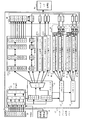
図1は、本発明の第1の実施形態に係る撮像装置示すブロック図である。
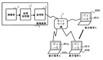
図1において撮像装置5には画像処理部1、撮像部2、及び通信部3の大きく分けて3つの構成要素が存在する。撮像部2は、映像が入射されるレンズ210、レンズで集められた光を電気信号に変換するセンサー220、センサー220から得られる信号を現像する現像処理部230からなる。
(First embodiment)
FIG. 1 is a block diagram showing an imaging apparatus according to the first embodiment of the present invention.
In FIG. 1, the
現像された信号は画像データとして画像処理部1に与えられ、そこで符号化などの処理を経た後、通信部3に符号化データとして与えられる。通信部3では、ネットワーク制御部310が入力された符号化データを送出するネットワークの形態に応じてパケット化するなどの処理を行い、ネットワークインタフェース320に対して送信用データとして受け渡す。ネットワークインタフェース320はネットワーク網4に対してそのネットワークの形態に応じた形でデータを送出する。ネットワーク網4はEthernet(登録商標)等の有線LAN、IEEE802.11b等に代表される形式の無線LAN、もしくはISDN等の公衆回線網などを代表的なものとして想定することができる。
The developed signal is provided as image data to the
なお、本実施形態では図1において画像処理部1、撮像部2、通信部3はそれぞれ別のブロックとして記述しているが、本実施形態を実ハードウェアで構成する際には、これらのブロックをそれぞれ別のICとして実現する、もしくは各部のいくつかの部分(例えば現像処理部230と画像処理部1とネットワーク制御部310)をまとめて1チップ上に実現するなどの様々な実現形態が可能であり、その形態は本実施形態において制限されるものではない。
In the present embodiment, the
図2は、画像処理部1の詳細な構成を示すブロック図である。
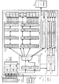
図2において、画像処理部1にはフレームバッファ10、画像データDMAC(ダイレクトメモリアクセス・コントローラ)20、ラスタ/ブロック変換用メモリ40、コーデック処理部50、符号化データDMAC60、制御用シーケンサ70、画像処理用メモリ11、データバッファ12がそれぞれ示されている。制御用シーケンサ70は、この画像処理部1の中の画像データDMAC20、ラスタ/ブロック変換用メモリ40、コーデック処理部50、符号化データDMAC60とそれぞれ制御用信号線で接続されており、これらの各ユニットの制御を実施する。更に、現像処理部230とは、フレームデータ転送完了割込み信号線、通信部3とは画像−通信部間制御信号71で接続され、相互に信号をやり取りして動きを制御する。また、コーデック処理部50は、画像処理用メモリ11と接続され、このメモリを利用して各種画像処理を実施する。更に、コーデック処理部50は内部にパラメータレジスタ51を持っており、このパラメータレジスタに対して制御用シーケンサ70が書き込んだ値に従って、各種画像処理を実施するものとする。
FIG. 2 is a block diagram illustrating a detailed configuration of the
In FIG. 2, an
なお、フレームバッファ10、画像処理用メモリ11、データバッファ12のそれぞれは画像処理部のそれ以外の構成要素が1つのICの中で実現される場合に、それらと同一のIC上のオンチップメモリとして構成することや、ICの外部でそのICと接続されるメモリデバイス(例えばSDR(Single Data Rate)又はDDR(Double Data Rate)のSDRAM(シンクロナスDRAM)など)として実現することが可能である。また、そのメモリもそれぞれを別のメモリデバイス上に配することや1つの同じメモリデバイス上に配置するなど、様々な構成をとることが可能である。
Each of the
以下、撮像装置5の基本動作等について図1、2を用いて詳細に説明する。
図1において、まず、撮影部2のレンズ210によって集められた光の画像情報がセンサー220によって電気信号として取り込まれる。このセンサー220はCCDイメージセンサー、又はCMOSイメージセンサーなどを利用することが可能である。本実施形態においては、正方画素のプログレッシブ形式のCCDであるとする。また、その有効画素数は640×480のいわゆるVGAサイズであり、1/30秒毎に1フレームのVGA画像を出力することができるものとする。即ち、本実施形態での1映像期間は1/30秒(およそ33.3ms)であるとする。センサー220で光電変換されて電気信号として取り込まれた画像データは、順次読み出され現像処理部230に渡される。現像処理部230では、センサー220から得られた画像データを信号処理して、輝度信号と色差信号を作り出し、後段で処理しやすい形式にして出力する。仮にここでは、YUV422形式で出力されるものとする。
Hereinafter, basic operations and the like of the
In FIG. 1, first, image information of light collected by the
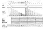
撮像部2の現像処理部230でYUV422形式にされた画像データは画像処理部1のフレームバッファ10にフレーム単位で格納される。その後の動作を図2及び図3のタイミングチャートを用いて説明する。
The image data converted into the YUV422 format by the
現像処理部230から出力されたデータはフレームバッファ10にフレーム単位で格納される。フレームバッファ10は図3に示すように内部はダブルバッファ形式になっており、第n番目のフレームと第n+1番目のフレームの画像データがそれぞれ別の領域(バッファA及びB)に格納されるようになっている。そのため、第nフレームの画像データがある映像期間に例えばバッファAに蓄えられた場合、それを読み出して次の映像期間で利用している間に、第n+1フレームの画像データをバッファBに蓄えていくことが可能になる。
Data output from the
今、第nフレームのフレームバッファ10のバッファAへの蓄積が完了したとする。すると、現像処理部230から制御用シーケンサ70に対してフレームデータの転送完了割込みが発生する(図3矢印1)。
Assume that the accumulation of the nth frame in the buffer A of the
転送完了割込みを受けて、制御用シーケンサ70は、まずコーデック処理部51のパラメータレジスタ51に対してどのような処理をコーデック処理部でおこなうかを指示するためのパラメータをセットする(図3矢印2a)。本実施形態では、このコーデック処理部はJPEGの圧縮処理をおこなうものとする。その場合、例えば映像の圧縮の度合いを示すQ値などがその圧縮のパラメータの代表的な例となる。
Upon receiving the transfer completion interrupt, the
パラメータレジスタ51へのパラメータのセットが終了すると、次いで制御用シーケンサ70は画像データDMAC20に対して、第nフレームの画像データをフレームバッファ10のバッファAから読み出して、コーデック処理部50に対してデータを供給するための転送を開始するように指示をする(図3矢印3a)。
When the parameter setting to the
指示を受けた画像データDMAC20はフレームバッファ10のバッファAから第nフレームの画像データを順に読み出して、ラスタ/ブロック変換用メモリ40に供給する。コーデック処理部50でJPEGの処理をおこなうためには、8×8の画素のブロック単位でデータを供給する必要があるので、このラスタ/ブロック変換用メモリ40でそのようにデータを変換してコーデック処理部50に供給する(図3矢印4a)。
Receiving the instruction, the
コーデック処理部50はラスタ/ブロック変換用メモリ40から与えられた画像データをパラメータレジスタ51に設定されたパラメータの値に従ってJPEG圧縮し、符号化データJPEGaとする。なお、本実施形態のこの最初の圧縮ではQ値=Qaとして圧縮しているとする。コーデック処理部50によって圧縮された符号化データは順次符号化データDMAC60に受け渡され、符号化データDMAC60はデータバッファ12に対して一定の単位で符号化データを転送する。そして第nフレームの画像データより作成された全ての符号化データの転送を完了した時点で、制御用シーケンサ70は通信部3に対して符号化データの転送完了割込みを送出する(図3矢印5a)。この割り込み通知は画像−通信部間制御信号71を介して伝達される。
The
通信部3では符号化データの転送完了割込みを受けて、ネットワーク制御部310がデータバッファ12から符号化データを読み出し、その符号化データを送出するネットワークの形態に応じてパケット化するなどの処理を行い、ネットワークインタフェース320に対して受け渡す。ネットワークインタフェース320はネットワーク網4に対してそのネットワークの形態に応じた形でデータを送出する。
The
図4は、本実施形態に係る撮像装置5を用いたシステムの構成例を示した図である。
ネットワーク網4には表示端末400が接続され、端末上のビューワ401を利用してユーザは撮像装置5が撮影した画像を表示する。図4では400aから400hまで合計8つの表示端末が存在し(うち5つは図示せず)、それぞれの表示端末上でビューワ401aから401hが動作し、各ユーザがそれを利用しているものとする。
FIG. 4 is a diagram illustrating a configuration example of a system using the
A display terminal 400 is connected to the
図4に示すようなシステムにおいて、ユーザが接続されるネットワーク環境及びユーザが必要とする画像品質等は様々である。もし、ユーザの求める画像品質がコーデック処理部50のパラメータレジスタ51に対して与えるパラメータの観点から見て同一のパラメータで実現できるようであれば、撮像装置5の通信部3のネットワーク制御部310が個々のユーザの端末に向けてデータを送出するようにする際に、同一の符号化データをコピーしてネットワークインタフェース320に受け渡すことによって複数のユーザに映像データをサービスすることが可能である。
In the system as shown in FIG. 4, the network environment to which the user is connected and the image quality required by the user are various. If the image quality desired by the user can be realized with the same parameters in terms of the parameters given to the
しかし、各ユーザが異なる画像品質のパラメータを要求するような場合においては、そのようにコピーするだけでは実現できない。また、ユーザの表示端末400上でコマ落ちさせることなく滑らかに動画像を表示させるようにするためには、1映像期間内(本実施形態では1/30秒(約33.3ms))の中で各ユーザが求める画像処理をそれぞれ行う必要がある。以下、そのような場合の撮像装置5の動作について図1〜4を用いながら説明する。先に図2、3を用いてその動作の基本は説明しているので、複数ユーザからの要求に答えるための動作と、それを受けての一連の動作の流れを説明する。
However, in the case where each user requires different image quality parameters, it cannot be realized simply by copying as such. In addition, in order to display a moving image smoothly without dropping frames on the display terminal 400 of the user, within one video period (in this embodiment, 1/30 seconds (about 33.3 ms)). Thus, it is necessary to perform image processing required by each user. Hereinafter, the operation of the
いま、図4において表示端末400aから400hを利用している各ユーザが、それぞれ、Q=Qa〜Qhで表されるQ値を持つJPEG画像を欲しているものとする。通信部3のネットワーク制御部310の中にある処理性能判断部311は、各端末から要求の出ている処理の内容を、1映像期間内に全て画像処理部で処理させることが可能であるかどうかの判断を行う。本実施形態では、予め処理内容(処理の種類、扱うデータ量、圧縮度など)から画像処理部の処理性能を評価するテーブルを引き、その結果Q=Qa〜Qhで表されるそれぞれのQ値を持つJPEG画像の処理を行うことが問題ないと判断し、画像処理部に対して処理の指示を出す。この指示は、図2の画像−通信部間制御信号71を利用して画像処理部1の制御用シーケンサ70に対して伝達される。
Now, it is assumed that each user using the
なお、本実施形態において処理性能判断部311は、通信部3のネットワーク制御部310の中にあるとしたが、例えば、画像処理部1の中に配することや、画像処理部1の制御用シーケンサ70に組み込まれた機能の一部として実装することも可能であり、その機能実現のためには、その位置は基本的には本実施形態において制限されるものではない。
In this embodiment, the processing
仮に、処理性能判断部311が制御用シーケンサ70に組み込まれていた場合には、各端末から要求の出ている処理内容がネットワーク制御部310を経由して、画像−通信部間制御信号71を介して制御用シーケンサ70内の処理性能判断部311に伝達され、その情報を用いて上記判断を実施することになる。但し、この場合は、既に処理性能判断部311が圧縮処理等の画像処理をこれ以上受け入れられないと判断している場合であっても、その判断部は制御用シーケンサ70内部にあるため、新規のユーザ要求が画像−通信部間制御信号71を介して制御用シーケンサ70内の処理性能判断部311にまで伝達され、そのユーザ要求への拒否回答が同じ経路を帰っていくことになる。また、ネットワーク上のユーザからの要求は映像期間とは同期せずに不定期に送付されてくるため、制御用シーケンサ70にもデータが不定期に送信されることになり、制御用シーケンサが予期せぬタイミングの要求に対応しなくてはならなくなるなど、結果として画像処理部1の制御に悪影響を及ぼす可能性がある。
If the processing
一方、処理性能判断部311がネットワーク制御部310の中にある場合はユーザ要求に対しての処理は基本的にネットワーク制御部310の中で判断され、必要のある場合のみ画像−通信部間制御信号71を介して制御用シーケンサ70に対して要求が伝達される。また、そのデータの伝達タイミングも映像期間と同期した一定のタイミングで与えることが可能である。このように必要なデータ伝送のみを実施してなるべく全体の処理負荷を減らすという観点から考えると、本実施形態のように処理性能判断部311は通信部3のネットワーク制御部310の中にあるほうが好ましい。
On the other hand, when the processing
図3において、Q=Qaの圧縮パラメータを用いた画像圧縮処理が終了し、JPEGaの符号化データの転送完了割込みを送出した(図3矢印5a)ことを制御用シーケンサ70が認識すると、制御用シーケンサ70は次に求められている画像処理のパラメータを調べる。そして、図3のように次に求められている圧縮に利用すべきパラメータQ=Qbをコーデック処理部50のパラメータレジスタ51に対して設定する(図3矢印2b)。
In FIG. 3, when the
それ以降の動作はQ=Qaの時と同様であり、パラメータレジスタ51へのパラメータのセットが終了すると、次いで制御用シーケンサ70は画像データDMAC20に対して、第nフレームの画像データをフレームバッファ10のバッファAから読み出して、コーデック処理部50に対してデータを供給するための転送を開始するように指示をする(図3矢印3b)。次いで指示を受けた画像データDMAC20はフレームバッファ10のバッファAから第nフレームの画像データを順に読み出して、ラスタ/ブロック変換用メモリ40に供給し、8×8の画素のブロック単位に変換されて画像データはコーデック処理部50に供給される(図3矢印4b)。
The subsequent operation is the same as when Q = Qa. When the parameter setting to the
コーデック処理部50は、ラスタ/ブロック変換用メモリ40から与えられた画像データをパラメータレジスタ51に設定されたパラメータの値(この時点ではQ=Qb)に従ってJPEG圧縮し、符号化データJPEGbとする。コーデック処理部50によって圧縮された符号化データは順次符号化データDMAC60に受け渡され、符号化データDMAC60はデータバッファ12に対して一定の単位で符号化データを転送する。そして第nフレームの画像データより作成されたQ=Qb時のすべての符号化データ転送を完了した時点で、制御用シーケンサ70は通信部3に対してQ=Qb時のJPEGbの符号化データ転送完了割込みを送出する(図3矢印5b)。
The
通信部3ではQ=Qb時で処理を行った符号化データの転送完了割込みを受けて、ネットワーク制御部310がデータバッファ12から符号化データを読み出し、Q=Qbでの処理要求を出していた表示端末400bに対して符号化データを送出するようにアドレス処理等を実施する。ネットワークインタフェース320はネットワーク網4を介して表示端末400bに対してデータを送出する。
The
この一連の動作が個々のユーザが要求する異なるQ値に応じて複数回1映像期間内に繰り返される。本実施形態では、処理性能判断部311が1映像期間内に実現可能であると判断したQaからQhに対応する合計8回のパラメータ設定とそれに伴う画像圧縮処理が1映像期間内に実施されている。このようにすることによって、複数の処理ユニットを並列に実装すること無しに1つのコーデックを用いて1映像期間内に複数回の画像圧縮処理が可能になり、ネットワークの先の様々な要求を持つユーザに対して実時間性を守って複数のサービスを提供することが可能になる。
This series of operations is repeated a plurality of times within one video period according to different Q values required by individual users. In the present embodiment, a total of eight parameter settings corresponding to Qa to Qh determined by the processing
例えば、複数のユーザの表示端末上でコマ落ちさせることなく滑らかに異なる品質の動画像を表示させることが可能になる。また、複数の処理ユニットを並列に実装する必要がなくなることから、基板もしくはチップ面積を小さくし、消費電力等も削減できるので、結果として小型のネットワークカメラを提供できるようになる。 For example, it is possible to smoothly display moving images of different quality without dropping frames on the display terminals of a plurality of users. In addition, since it is not necessary to mount a plurality of processing units in parallel, the substrate or chip area can be reduced, and power consumption can be reduced. As a result, a small network camera can be provided.
また、特に処理性能判断部311が的確に判断することによって、画像圧縮処理などのユニット性能をその性能の極限まで無駄なく利用することが可能になり、1つのコーデックを用いて1映像期間内により多くのユーザに実時間性を守って複数のサービスを提供することが可能になる。更に、処理性能判断部311をネットワーク制御部310の中に配することによって、より内部のデータ通信を減らしながら、上記機能を実現することができるようになり、全体としての処理性能の向上や消費電力の削減などの効果がある。
In particular, when the processing
(第2の実施形態)
第1の実施形態においては、ユーザの要求する画像処理の相違はQ値であるとした。しかし、別の局面ではユーザの要求する画像処理はQ値だけにとどまらない場合がある。そのような場合について図1、図4、及び図5から図7を用いて説明する。図1、図4は図としての構成要素は同一であるので第1の実施形態のものを流用する。
(Second Embodiment)
In the first embodiment, the difference in image processing requested by the user is the Q value. However, in another aspect, the image processing requested by the user may not be limited to the Q value. Such a case will be described with reference to FIGS. 1, 4, and 5 to 7. FIG. Since FIG. 1 and FIG. 4 are the same as the constituent elements shown in the figure, those of the first embodiment are used.
図1において、本実施形態では、撮像部2のセンサー220は、全画素読出し方式のCMOSセンサーであり、その有効画素数は1600×1200のいわゆるUXGAサイズであるとする。そして、その画素形態は正方画素であり1/30秒毎に1フレーム分のUXGA画像を出力することができるものとする。即ち、本実施形態での1映像期間は1/30秒(およそ33.3ms)であるとする。
In FIG. 1, in this embodiment, the
このような条件下で、図4における各ユーザは、UXGAの画像の内部で任意のVGAサイズ以下の画像領域を設定し、その部分画像を切出して利用しているものとする。UXGAの画像サイズの中でどの部分の画像を切出して利用しているかの例を図5に示す。 Under such conditions, it is assumed that each user in FIG. 4 sets an image area having an arbitrary VGA size or less inside a UXGA image, and uses the partial image cut out. FIG. 5 shows an example of which part of the image of UXGA is cut out and used.
図5では、図4の表示端末400aのビューワ401aに表示される画像領域をa、表示端末400bのビューワ401bに表示される画像領域をbというようにして表示端末400hに対応する画像領域hまでが示されている。ここでは、表示端末400aから400fまでのユーザがVGAサイズ(640×480)、表示端末400g及び400hのユーザがQVGAサイズ(320x240)の画像サイズの映像データを利用している。
In FIG. 5, the image area displayed on the viewer 401a of the
また、通信部3のネットワーク制御部310の中にある処理性能判断部311は、各端末から要求の出ている処理の内容を、1映像期間内に全て画像処理部で処理させることが可能であるかどうかの判断を行う。本実施形態では、図5で示されている画像領域の全ての切出し処理、及びその映像を利用した画像処理部におけるJPEG画像の処理を行うことが問題ないと判断し、画像処理部に対して処理の指示を出すものとする。
In addition, the processing
なお、本実施形態において処理性能判断部311は通信部3のネットワーク制御部310の中にあるとしたが、第1の実施形態と同様に例えば、画像処理部1の中に配することや、画像処理部1の制御用シーケンサ70に組み込まれた機能の一部として実装することも可能であり、その位置は本実施形態において制限されるものではない。但し、第1の実施形態と同様に必要なデータ伝送のみを実施してなるべく全体の処理負荷を減らすという観点から考えると、本実施形態のように処理性能判断部311は通信部3のネットワーク制御部310の中にあるほうが好ましい。
In this embodiment, the processing
このような前提の下で、本実施形態における画像処理部1の動作を図1及び図4、5を参照しながら図6及び図7を用いて説明する。
Under such a premise, the operation of the
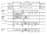
図6において、現像処理部230から出力されたUXGAサイズの画像データは、フレームバッファ10にフレーム単位で格納される。フレームバッファ10は、図7に示すように内部はダブルバッファ形式になっており、第n番目のフレームと第n+1番目のフレームの画像データがそれぞれ別の領域(バッファA及びB)に格納されるようになっている。
In FIG. 6, UXGA size image data output from the
今、第nフレームのフレームバッファ10のバッファAへの蓄積が完了したとする。すると、現像処理部230から制御用シーケンサ70に対してフレームデータの転送完了割込みが発生する(図7矢印1)。
Assume that the accumulation of the nth frame in the buffer A of the
転送完了割込みを受けて、制御用シーケンサ70は、まず第1の実施形態と同様にコーデック処理部51のパラメータレジスタ51に対してどのような処理をコーデック処理部でおこなうかを指示するためのパラメータをセットする(図7矢印2a)。本実施形態では、このコーデック処理部はJPEGの圧縮処理をおこなうものとする。その場合、例えば映像の圧縮の度合いを示すQ値などがその圧縮のパラメータの代表的な例であり、この時点では表示端末400aが要求しているQ=Qaが設定されたとする。
Upon receipt of the transfer completion interrupt, the
次いで制御用シーケンサ70は画像データDMAC20に対して、第nフレームの画像データをフレームバッファ10のバッファAから読み出して、コーデック処理部50に対してデータを供給するための転送を開始するように指示をする(図7矢印3a)。その際、制御用シーケンサ70は画像データDMAC20の転送領域設定レジスタ21に対してフレームバッファ10に蓄えられたUXGAの画像データからどの領域を読み出してコーデック処理部50に与えるかを指示するための領域パラメータをセットする。
Next, the
この領域パラメータは、図6の画像−通信部間制御信号71を利用して予め画像処理部1の制御用シーケンサ70に対してネットワーク上の各表示端末400a〜hより要求がなされているものとする。この時点では、表示端末400aが要求しているVGAサイズの画像(図5の領域a)を示すように、コーデック処理部50に与えるデータの開始位置を示す座標データと、画像サイズ(VGA)を示すデータが制御用シーケンサ70に対して与えられ、制御用シーケンサ70はそれらのデータから求めた転送領域情報を領域パラメータとして転送領域設定レジスタ21に設定する。
This area parameter is requested in advance from the
領域及びサイズの指示を受けた画像データDMAC20は、フレームバッファ10のバッファAから第nフレームの指定領域の画像データを順に読み出して、ラスタ/ブロック変換用メモリ40に供給する。ラスタ/ブロック変換用メモリ部では8×8のブロック単位にデータを変換してコーデック処理部50に供給する(図7矢印4a)。
The
コーデック処理部50は、ラスタ/ブロック変換用メモリ40から与えられた画像データをパラメータレジスタ51に設定されたパラメータの値(Q=Qa)に従ってJPEG圧縮し、符号化データJPEGaとする。コーデック処理部50によって圧縮された符号化データは順次符号化データDMAC60に受け渡され、符号化データDMAC60はデータバッファ12に対して一定の単位で符号化データを転送する。そして第nフレームにおいて表示端末400aが指定した領域を構成する画像データより作成されるすべての符号化データの転送を完了した時点で、制御用シーケンサ70は通信部3に対して符号化データの転送完了割込みを送出する(図7矢印5a)。この割り込み通知は画像−通信部間制御信号71を介して伝達される。
The
通信部3では、符号化データの転送完了割込みを受けて、ネットワーク制御部310がデータバッファ12から符号化データを読み出し、その符号化データを送出するネットワークの形態に応じてパケット化するなどの処理を行い、ネットワークインタフェース320に対して受け渡す。ネットワークインタフェース320はネットワーク網4に対してそのネットワークの形態に応じた形でデータを表示端末400aに向けて送出する。表示端末400aでは受信したデータを展開し、VGAサイズのデータとしてビューワ401aに表示する。
In the
一方、図7において、表示端末400a向けの領域パラメータとQ=Qaの圧縮パラメータを用いた画像圧縮処理が終了し、JPEGaの符号化データの転送完了割込みを送出した(図7矢印5a)ことを制御用シーケンサ70が認識すると、制御用シーケンサ70は次に求められている画像処理のパラメータを調べる。そして、図7のように次に求められている圧縮に利用すべきパラメータQ=Qbをコーデック処理部50のパラメータレジスタ51に対して設定する(図7矢印2b)。
On the other hand, in FIG. 7, the image compression processing using the region parameter for the
次いで、画像データDMAC20に対して、第nフレームの画像データをフレームバッファ10のバッファAから読み出す際に、どの部分のデータをどのようなサイズで読み出すかを表示端末400bからの指示に基づき画像データDMAC20の転送領域レジスタ21に対して設定し、コーデック処理部50に対してデータを供給するための転送を開始するように指示をする(図7矢印3b)。それ以降の動作は表示端末400aに対して行った処理と同様である。
Next, when reading out the image data of the nth frame from the buffer A of the
この一連の動作が個々のユーザが要求する異なるパラメータ(画像領域及びQ値等)に応じて複数回1映像期間内に繰り返される。本実施形態では、図5に示したように異なる切出し位置とサイズ及び圧縮パラメータの指定に基づき、合計8回のパラメータ設定とそれに伴う画像圧縮処理が1映像期間内に実施されている。このようにすることによって、1つのコーデックを用いて1映像期間内に複数の領域の画像圧縮処理が可能になり、ネットワークの先の様々な要求を持つユーザに対して実時間性を守って複数のサービスを提供することが可能になる。また、1つの高解像度の画像から任意の位置と任意のサイズを指定して複数の部分領域画像を作成し、1映像期間内におけるそれら複数の部分領域画像を用いた画像処理が可能となる。 This series of operations is repeated a plurality of times within one video period according to different parameters (image area, Q value, etc.) required by each user. In the present embodiment, as shown in FIG. 5, a total of eight parameter settings and accompanying image compression processing are performed within one video period based on designation of different cutout positions, sizes, and compression parameters. In this way, it is possible to perform image compression processing of a plurality of areas within one video period using one codec, and to protect a plurality of users who have various requests over the network in real time. It becomes possible to provide services. In addition, a plurality of partial area images can be created by designating an arbitrary position and an arbitrary size from one high-resolution image, and image processing using the plurality of partial area images within one video period can be performed.
(第3の実施形態)
第1及び第2の実施形態では撮影した元の画像と同じ解像度の画像を扱っている場合を例としたが、撮影した画像と同じ画角の映像を、解像度を落とすことにより小さな画面表示で利用したいという場合も考えられる。
(Third embodiment)
In the first and second embodiments, an example in which an image with the same resolution as the original image taken is handled is taken as an example, but an image with the same angle of view as the taken image can be displayed on a small screen by reducing the resolution. You may want to use it.
そのような場合について図1、図4、及び図8から図11を用いて説明する。図1、図4は図としての構成要素は同一であるので第1の実施形態のものを流用する。なお、本実施形態では第2の実施形態と同様、図1における撮像部2のセンサー220は、全画素読出し方式のCMOSセンサーであり、その有効画素数は1600×1200のいわゆるUXGAサイズであるとする。そして、その画素形態は正方画素であり1/30秒毎に1フレーム分のUXGA画像を出力することができるものとする。即ち、本実施形態での1映像期間は1/30秒(およそ33.3ms)であるとする。
Such a case will be described with reference to FIGS. 1, 4, and 8 to 11. Since FIG. 1 and FIG. 4 are the same as the constituent elements shown in the figure, those of the first embodiment are used. In this embodiment, as in the second embodiment, the
図8は、画像処理部1の中に解像度変換部30が存在する場合の構成を示した図である。第2の実施形態の図6と比較すると画像データDMAC20とラスタ/ブロック変換用メモリ40との間のデータパスが2つに分かれ、その片方に解像度変換部が入っている。制御用シーケンサ70は必要に応じてデータパスを切り替え、解像度変換部30を通してデータを供給する。
FIG. 8 is a diagram showing a configuration when the
図9は、本実施形態における画像処理部の動作を示した図であり、図10は、本実施形態における要求されている画角と解像度を示した図である。
図10からわかるように、本実施形態ではUXGAサイズのデータから同じ画角でVGAサイズに変換した画像を圧縮したもの(データa)、UXGAサイズの元データからVGAサイズで切出した画像を圧縮したもの(データb及びc)、そしてUXGAサイズの画像をそのまま圧縮したもの(データd)が要求されているとする。ここでデータaからdは図4における端末400aから400dの要求に対応している。
FIG. 9 is a diagram showing the operation of the image processing unit in the present embodiment, and FIG. 10 is a diagram showing the required angle of view and resolution in the present embodiment.
As can be seen from FIG. 10, in this embodiment, an image converted from UXGA size data to VGA size at the same angle of view is compressed (data a), and an image extracted from VUX size from the UXGA size original data is compressed. It is assumed that there is a request for data (data b and c) and a UXGA size image compressed as it is (data d). Here, data a to d correspond to requests from
図8において、現像処理部230から出力されたUXGAサイズの画像データは、フレームバッファ10にフレーム単位で格納される。フレームバッファ10は、図9に示すように内部はダブルバッファ形式になっており、第n番目のフレームと第n+1番目のフレームの画像データがそれぞれ別の領域(バッファA及びB)に格納されるようになっている。
In FIG. 8, UXGA size image data output from the
今、第nフレームのフレームバッファ10のバッファAへの蓄積が完了したとする。すると、現像処理部230から制御用シーケンサ70に対してフレームデータの転送完了割込みが発生する(図9矢印1)。
Assume that the accumulation of the nth frame in the buffer A of the
転送完了割込みを受けて、制御用シーケンサ70は、まず第2の実施形態と同様にコーデック処理部51のパラメータレジスタ51に対してどのような処理をコーデック処理部でおこなうかを指示するためのパラメータをセットする(図9矢印2a)。本実施形態では、このコーデック処理部はJPEGの圧縮処理をおこなうものとする。その場合、例えば映像の圧縮の度合いを示すQ値などがその圧縮のパラメータの代表的な例であり、この時点では表示端末400aが要求しているQ=Qaが設定されたとする。
Upon receiving the transfer completion interrupt, the
次いで、制御用シーケンサ70は解像度変換部30に対して、画像データDMAC20から入力されるUXGAサイズの画像データをVGAサイズに解像度変換するように指示をする(タイミング図示せず)。どのようなサイズに解像度変換するかについては図8の画像−通信部間制御信号71を利用して予め画像処理部1の制御用シーケンサ70に対してネットワーク上の表示端末400aより要求がなされているものとする。
Next, the
次いで、制御用シーケンサ70は、画像データDMAC20に対して、第nフレームの画像データをフレームバッファ10のバッファAから読み出して、解像度変換部30を経由してコーデック処理部50に対してデータを供給するための転送を開始するように指示をする(図9矢印3a)。本実施形態のこの時点においては、UXGAの全データを読み出して解像度変換部30に入力する必要があるので、そのように領域パラメータを転送領域設定レジスタ21に設定する。本実施形態では特に説明しないが、もし、ここでUXGAの領域のうち部分的に領域を指定して転送領域設定レジスタ21に設定した場合には、その領域のデータを読み出して解像度変換部30に与えることによって、任意の領域の画像を解像度変換できるようにすることが可能である。
Next, the
そのようにしてデータの転送が画像データDMAC20によりフレームバッファ10から解像度変換部30に対して開始されると、解像度変換部30は、UXGAからVGAへの解像度変換作業を開始する(図9矢印4)。そして、解像度変換を終了した画像データから順に、ラスタ/ブロック変換用メモリ40に供給する。ラスタ/ブロック変換用メモリ部では8×8のブロック単位にデータを変換してコーデック処理部50に供給する(図9矢印5)。
When the data transfer is started from the
コーデック処理部50は、ラスタ/ブロック変換用メモリ40から与えられた画像データをパラメータレジスタ51に設定されたパラメータの値(Q=Qa)に従ってJPEG圧縮し、符号化データとする。このデータaの符号化に要する時間が他のVGAの符号化処理に比べて多く要しているのは、本実施形態においては、VGAの元データとなるべきUXGAのデータをフレームバッファ10から読み出してVGAに解像度変換する部分が全体の処理速度を決める要因となっているからである。
The
コーデック処理部50によって圧縮された符号化データは、順次符号化データDMAC60に受け渡され、符号化データDMAC60はデータバッファ12に対して一定の単位で符号化データを転送する。そしてVGAを構成する全ての符号化データの転送を完了した時点で、制御用シーケンサ70は通信部3に対して符号化データの転送完了割込みを送出する(図9矢印6a)。この割り込み通知は画像−通信部間制御信号71を介して伝達される。
The encoded data compressed by the
通信部3では、符号化データの転送完了割込みを受けて、ネットワーク制御部310がデータバッファ12から符号化データを読み出し、その符号化データを送出するネットワークの形態に応じてパケット化するなどの処理を行い、ネットワークインタフェース320に対して受け渡す。ネットワークインタフェース320はネットワーク網4に対してそのネットワークの形態に応じた形でデータを表示端末400aに向けて送出する。表示端末400aでは受信したデータを展開し、VGAサイズのデータとしてビューワ401aに表示する。
In the
一方、図9において、表示端末400a向けの解像度変換とQ=Qaの圧縮パラメータを用いた画像圧縮処理が終了し、JPEG:VGA−aの符号化データの転送完了割込みを送出した(図9矢印6a)ことを制御用シーケンサ70が認識すると、制御用シーケンサ70は次に求められている画像処理のパラメータを調べる。そして、ここではQ=Qbをコーデック処理部50のパラメータレジスタ51に対して設定する(図9矢印2b)。
On the other hand, in FIG. 9, the resolution conversion for the
次いで、画像データDMAC20に対して、第nフレームの画像データをフレームバッファ10のバッファAから読み出す際に、図10のbで示されるVGAデータの開始座標とサイズ(VGA)から求められる転送領域情報を、表示端末400bからの指示に基づき画像データDMAC20の転送領域レジスタ21に対して設定する。その上でコーデック処理部50に対して、データを供給するための転送を開始するように指示をする(図9矢印3b)。それ以降の動作は第2の実施形態の表示端末400aに対して行った処理と同様であり、それが端末400cに対する切出しVGA画像データcの圧縮に関しても同様に実施される。
Next, when the
図9において、表示端末400c向けの画像圧縮処理が終了し、JPEGcの符号化データの転送完了割込みを送出した(図9矢印6c)ことを制御用シーケンサ70が認識すると、制御用シーケンサ70は、次に求められている画像処理のパラメータを調べる。ここでは、次に要求されている動作は、UXGAサイズの画像データdをその解像度のままJPEG圧縮して端末400dに対して送ることである。
In FIG. 9, when the
しかし、UXGAの画像データをそのまま圧縮して送ることは全体のシステム、特にコーデック処理等に非常に負荷をかけるので、本実施形態では、UXGA画像の1/2だけをこの1映像期間内に処理して、残りの1/2に関しては次の映像期間に実施することにしている。この判断は、予め通信部3のネットワーク制御部310の中にある処理性能判断部311によって判断され、その条件でよければサービスを開始することを表示端末400dのユーザに通知し、また、この映像を要求している端末400dのユーザもその条件を了解しているものとする。
However, since compressing and sending UXGA image data as it is puts a heavy load on the entire system, especially codec processing, in this embodiment, only ½ of the UXGA image is processed within this one video period. Then, the remaining half is executed in the next video period. This determination is determined in advance by the processing
その処理の手順は、他の画像の処理と同様に、圧縮に利用すべきパラメータQ=Qdのコーデック処理部50のパラメータレジスタ51に対する設定(図9矢印2d)、画像データDMAC20に対する転送領域レジスタ21の設定及び画像データの転送開始指示(図9矢印3d)となる。そして、画像データの転送が開始されると(図9矢印8)、コーデック処理部50は、指示されたパラメータを用いてJPEG圧縮を開始する。そしてUXGAの1/2のデータを圧縮してデータバッファ12に転送し終えた時点において、制御用シーケンサ70はデータバッファ通信部3に対してJPEGdの符号化データの転送完了割込みを送出する(図9矢印6d)。
The procedure of the processing is the same as the processing of other images, the setting of the parameter Q = Qd to be used for compression in the
このように1枚分のデータが完成する前に一旦処理を中断してその処理を通信部3に渡すことによって、データ通信における負荷の平準化などを通信部3側で考慮して配送することが可能になる。
In this way, the processing is temporarily interrupted before the data for one sheet is completed, and the processing is transferred to the
図11は、UXGAサイズの画像をJPEG圧縮する際に、連続する2つの映像期間を利用して実施する場合の動作を示した図である。
映像期間[1]は、図9の内容と同一である。映像期間[1]の後半でUXGAサイズデータのJPEG圧縮のうち1/2を行った場合、続く映像期間[2]でUXGAサイズデータのJPEG圧縮の残りを実施する必要がある。この場合、圧縮に利用する画像データは第nフレームのものであるが、その第nフレームの画像データはフレームバッファ10を構成するダブルバッファのうちバッファAに保存されているものである。
FIG. 11 is a diagram illustrating an operation in the case where the UXGA size image is subjected to JPEG compression using two consecutive video periods.
The video period [1] is the same as that shown in FIG. When 1/2 of the JPEG compression of UXGA size data is performed in the second half of the video period [1], it is necessary to perform the remainder of the JPEG compression of UXGA size data in the subsequent video period [2]. In this case, the image data used for compression is for the nth frame, but the image data for the nth frame is stored in the buffer A among the double buffers constituting the
映像期間[2]においてバッファAは、基本的には第n+2フレームのデータが入力されてくる領域であるので、第n+2フレームのデータによって第nフレームのデータが書き潰されないうちにUXGAサイズデータのJPEG圧縮の残り1/2を実施しなければならない。そのため、この圧縮の処理は映像期間[1]と違って映像期間[2]の先頭に位置するようにしている。また、このような順序で処理することによって、通信部3へのデータの受け渡しも連続したものとなり、その扱いがより簡単化される。
In the video period [2], the buffer A is basically an area where data of the (n + 2) th frame is inputted. Therefore, before the data of the (n + 2) th frame is overwritten by the data of the (n + 2) th frame, UXGA size data The remaining half of JPEG compression must be performed. Therefore, unlike the video period [1], this compression processing is positioned at the head of the video period [2]. Also, by processing in this order, data transfer to the
なお、本実施形態において処理性能判断部311は、通信部3のネットワーク制御部310の中にあるとしたが、第1の実施形態と同様に例えば、画像処理部1の中に配することや、画像処理部1の制御用シーケンサ70に組み込まれた機能の一部として実装することも可能であり、その位置は本実施形態において制限されるものではない。もし、処理性能判断部311が制御用シーケンサ70に組み込まれていた場合には、各端末から要求の出ている処理内容がネットワーク制御部310を経由して、画像−通信部間制御信号71を介して制御用シーケンサ70に伝達され、その情報を用いて上記判断を実施することになる。そして、判断結果のサービス提供の可否は画像−通信部間制御信号71を介してネットワーク制御部310に伝達され、ネットワーク制御部310が各端末にその情報を送信することになる。
In this embodiment, the processing
但し、第1の実施形態と同様に必要なデータ伝送のみを実施してなるべく全体の処理負荷を減らすという観点から考えると、本実施形態のように処理性能判断部311は通信部3のネットワーク制御部310の中にあるほうが好ましい。
However, from the viewpoint of reducing the overall processing load as much as possible by performing only necessary data transmission as in the first embodiment, the processing
このようにすることによって、1つのコーデックを用いて1映像期間内に複数の領域の画像圧縮処理、及び、複数の解像度を持つ画像の画像圧縮処理を行うことができる。特に、高解像度の撮影画像の任意領域を切出して解像度変換することによって得られる画像、及び部分的に切出して解像度変換はしない画像など、高解像度の映像からユーザの希望に基づく任意の画角と解像度にした画像を1つのコーデックを用いて1映像期間内に複数ユーザに対して処理することが可能になる。 In this way, it is possible to perform image compression processing for a plurality of regions and image compression processing for images having a plurality of resolutions within one video period using one codec. In particular, an arbitrary angle of view based on a user's request from a high-resolution video, such as an image obtained by cutting out an arbitrary area of a high-resolution captured image and converting the resolution, and an image partially cut out and not converted in resolution. It is possible to process an image having a resolution for a plurality of users within one video period using one codec.
また、本実施形態では、複数の映像期間を利用した高解像度データの処理を可能にしている。特に、本実施形態ではUXGAサイズのJPEG圧縮を連続する2映像期間に割り当て、かつその処理が時間的に連続するように処理順序を制御してサービスをしている。このようにすることによって、複数の映像期間に跨って高解像度データを保持するためのフレームバッファをその処理専用に持たなくてもすむようになり、メモリサイズを節約できるなどの効果がある。 In the present embodiment, high-resolution data processing using a plurality of video periods is enabled. In particular, in the present embodiment, UXGA size JPEG compression is assigned to two consecutive video periods, and the processing order is controlled so that the processing is temporally continuous, thereby providing a service. By doing so, there is no need to have a dedicated frame buffer for holding high-resolution data over a plurality of video periods, and the memory size can be saved.
但し、この処理順序の割り当て方法等は固定的なものではなく、他の処理に先んじて1映像区間の先頭で処理するなどユーザへのサービスポリシなどに応じて変更され得るものである。 However, the processing order assignment method and the like are not fixed, and can be changed according to the service policy to the user, such as processing at the head of one video section prior to other processing.
また、2以上の期間に跨って処理が必要になる場合は、複数映像期間に跨ってフレームデータが保持できるように、フレームバッファを構成することも可能であり、その持ち方はこの実施形態により制限されるものではない。 In addition, when processing is required over two or more periods, it is possible to configure a frame buffer so that the frame data can be held over a plurality of video periods. It is not limited.
(第4の実施形態)
第3の実施形態では、解像度変換を行った画像をそのまま順次圧縮処理していたため、解像度変換後の画像は1回しか利用できなかったが、場合によっては元画像に同じ解像度変換を行った画像に対して、異なる圧縮のパラメータで圧縮したいという要求がくることも考えられる。その場合、同じ解像度変換を2回実施することも一手法であるが、特に元データの画像解像度が高い場合には、その元画像のフレームバッファからの読出し及び解像度変換に時間を要することになり、1映像期間内に処理できる性能を下げることになる。
(Fourth embodiment)
In the third embodiment, since the images subjected to resolution conversion are sequentially subjected to compression processing as they are, the image after resolution conversion can be used only once. However, in some cases, an image obtained by performing the same resolution conversion on the original image On the other hand, there may be a demand for compression with different compression parameters. In that case, it is one method to perform the same resolution conversion twice, but it takes time to read the original image from the frame buffer and to convert the resolution especially when the image resolution of the original data is high. The performance that can be processed within one video period is lowered.
それを避けるために、後続の処理で同一の解像度変換処理を必要とする場合、もしくは一旦解像度変換した画像を利用して更なる解像度変換処理を実施することが有効である場合には、解像度変換した後の画像をコーデック処理部への処理に向けると同時に、一旦フレームバッファに貯めて後の処理で利用することが考えられる。そのような場合に関して図1、図4、及び図12から図14を用いて説明する。 To avoid this, if the same resolution conversion processing is required in subsequent processing, or if it is effective to perform further resolution conversion processing using the resolution-converted image, resolution conversion is effective. It is conceivable that the processed image is directed to the codec processing unit, and at the same time, temporarily stored in the frame buffer and used in the subsequent processing. Such a case will be described with reference to FIGS. 1, 4 and 12 to 14.
図1、図4は図としての構成要素は同一であるので第1の実施形態のものを流用する。なお、本実施形態では第2の実施形態と同様、図1における撮像部2のセンサー220は、全画素読出し方式のCMOSセンサーであり、その有効画素数は1600×1200のいわゆるUXGAサイズであるとする。そして、その画素形態は正方画素であり1/30秒毎に1フレーム分のUXGA画像を出力することができるものとする。即ち、本実施形態での1映像期間は1/30秒(およそ33.3ms)であるとする。
Since FIG. 1 and FIG. 4 are the same as the constituent elements shown in the figure, those of the first embodiment are used. In this embodiment, as in the second embodiment, the
図12は、画像処理部1の中に解像度変換部30の処理後のデータを一旦蓄積するためのフレームバッファ(2)13が存在する場合の構成を示した図である。第3の実施形態の図8と比較すると、フレームバッファ(2)13が機能ブロックとして追加され、解像度変換部30からのデータパスと画像データDMAC20へのデータパスが追加されている。
FIG. 12 is a diagram showing a configuration when the frame buffer (2) 13 for temporarily storing data processed by the
なお、このフレームバッファ(2)13は、フレームバッファ10、画像処理用メモリ11、データバッファ12と同様に、画像処理部のそれ以外の構成要素が1つのICの中で実現される場合に、それらと同一のIC上のオンチップメモリとして構成することや、ICの外部でそのICと接続されるメモリデバイス(例えばSDR又はDDRのSDRAMなど)として実現することが可能である。また、そのメモリもそれぞれを別のメモリデバイス上に配することや1つの同じメモリデバイス上に配置するなど、様々な構成をとることが可能である。
The frame buffer (2) 13 is similar to the
図13は、本実施形態における画像処理部の動作を示す図であり、図14は、本実施形態における要求されている画角と解像度を示す図である。図14からわかるように、本実施形態では、UXGAサイズのデータから同じ画角でVGAサイズに変換した画像を異なる2種の圧縮パラメータで圧縮するもの(データa、b)、更に、それと同じ画角でQVGAサイズの画像(データd)、UXGAサイズの元データからVGAサイズで切出した画像を圧縮したもの(データc)、そしてUXGAサイズの画像をそのまま圧縮したもの(データe)が要求されているとする。ここでデータaからeは図4における端末400aから400eの要求に対応している。
FIG. 13 is a diagram illustrating the operation of the image processing unit in the present embodiment, and FIG. 14 is a diagram illustrating the required angle of view and resolution in the present embodiment. As can be seen from FIG. 14, in this embodiment, an image converted from UXGA size data to VGA size at the same angle of view is compressed with two different compression parameters (data a and b), and the same image as that. QVGA size image (data d) at the corner, compressed image of VGA size extracted from UXGA size original data (data c), and compressed UXGA size image as it is (data e) Suppose that Here, data a to e correspond to requests from
図13において、画像の処理の流れは途中までは第3の実施形態の図9と同じである。異なるのは、解像度変換部30がUXGAからVGAへの解像度変換作業を開始すると(図13矢印4a)、解像度変換を終了した画像データから順に、ラスタ/ブロック変換用メモリ40に供給すると同時に、フレームバッファ(2)13に転送してVGA画像の蓄積を開始することである。図13矢印9)。解像度変換した画像をフレームバッファ(2)13に蓄積するかどうかの判断に関しては、ネットワーク上の各表示端末からの要求に基づいて、ネットワーク制御部310から画像−通信部間制御信号71を利用して予め画像処理部1の制御用シーケンサ70に対して設定がなされているものとする。
In FIG. 13, the flow of image processing is the same as that of FIG. 9 of the third embodiment up to the middle. The difference is that when the
コーデック処理部50は、ラスタ/ブロック変換用メモリ40から与えられた画像データ(図13矢印5a)をパラメータレジスタ51に設定されたパラメータの値(Q=Qa)に従ってJPEG圧縮して符号化データJPEG:VGA−aとし、それを符号化データDMAC60が順次データバッファ12に転送する。そして、すべての符号化データの転送を完了した時点で、制御用シーケンサ70は、データバッファ通信部3に対して符号化データの転送完了割込みを送出する。(図12矢印6a)この割り込み通知は画像−通信部間制御信号71を介して伝達される。この画像は、通信部3が端末400aに対して送信する。
The
次いで、制御用シーケンサ70は、次に求められている画像処理のパラメータ及び画角、解像度を調べる。そして、次に求められている圧縮に利用すべきパラメータQ=Qbをコーデック処理部50のパラメータレジスタ51に対して設定する(図12矢印2b)。
Next, the
次いで、画像データDMAC20に対して、先にVGAに解像度変換したデータを利用して画像の圧縮処理をするべく、転送領域レジスタ21に対してデータの転送元をフレームバッファ(2)13に設定し、コーデック処理部50に対してデータを供給するための転送を開始するように指示をする(図12矢印3b)。画像データDMAC20は、フレームバッファ(2)13よりVGAデータを読出し、それをラスタ/ブロック変換用メモリ40を経由してブロック化したのち、コーデック処理部50に供給する。コーデック処理部50は設定されているパラメータQbを利用して圧縮処理を実施していく。
Next, for the
その後、一旦VGAサイズの切出し画像の圧縮を行った後、次に元のUXGA画像と同じ画角でQVGAサイズの画像データ(データd)の処理を要求されている。既に同じ画角のVGA画像がフレームバッファ(2)13に蓄えられており、要求されているQVGA画像は蓄えられているVGA画像を利用して解像度変換することで容易に作成することができる。 Thereafter, after the VGA size cut image is once compressed, the processing of the QVGA size image data (data d) is requested at the same angle of view as the original UXGA image. VGA images having the same angle of view are already stored in the frame buffer (2) 13, and the requested QVGA image can be easily created by converting the resolution using the stored VGA image.
そこで、制御用シーケンサ70は、まず、解像度変換部30に対してVGA⇒QVGA変換をし実施するように指示をする(タイミング図示せず)。次いで、画像データDMAC20に対して、既にVGAに解像度変換したデータを利用して画像の解像度変換をするように、転送領域レジスタ21に対してデータの転送元をフレームバッファ(2)13に設定し、解像度変換部30に対してデータを供給するための転送を開始するように指示をする(図12矢印3d)。
Therefore, the
画像データDMAC20は、フレームバッファ(2)13よりVGAデータを読出し、それを解像度変換部30に供給する。解像度変換部30でVGAからQVGAに変換された画像データは、ラスタ/ブロック変換用メモリ40を経由してブロック化されたのち、コーデック処理部50に供給される(図12矢印5d)。コーデック処理部50は設定されているパラメータQdを利用して圧縮処理を実施していく。以降は、第3の実施形態と同様であるので、説明を省略する。
The
なお、本実施形態においても処理性能判断部311は、通信部3のネットワーク制御部310の中にあるとしたが、第1の実施形態と同様に、例えば、画像処理部1の中に配することや、画像処理部1の制御用シーケンサ70に組み込まれた機能の一部として実装することも可能であり、その位置は本実施形態において制限されるものではない。但し、第1の実施形態と同様に、必要なデータ伝送のみを実施してなるべく全体の処理負荷を減らすという観点から考えると、本実施形態のように処理性能判断部311は、通信部3のネットワーク制御部310の中にあるほうが好ましい。
In this embodiment, the processing
このようにすることによって、第3の実施形態での効果に加えて、1つのコーデックを用いて1映像期間内に複数の領域の画像圧縮処理を効率よく実施することが可能になる。特に、解像度変換した画像をコーデック処理部で利用するのと並行してフレームバッファに蓄積することができるようにすることで、同一画角の画像の解像度変換処理を複数の表示側端末から要求されるような場合に、同じ解像度変換を繰り返したりすることや、必要以上に詳細なデータを元に圧縮することをせずにすむようになり、1映像期間内における処理性能を向上させ、より多くのユーザからの異なる要求に対応した処理を行うことが可能になる。 By doing so, in addition to the effects of the third embodiment, it is possible to efficiently perform image compression processing of a plurality of regions within one video period using one codec. In particular, by allowing the resolution-converted image to be stored in the frame buffer in parallel with the codec processing unit being used, resolution conversion processing for images with the same angle of view is required from multiple display-side terminals. In such a case, it is not necessary to repeat the same resolution conversion or to compress the data based on detailed data more than necessary. Processing corresponding to different requests from the user can be performed.
(第5の実施形態)
第4の実施形態では、UXGA画像からVGA画像を作り、その作ったVGAの画像をコーデック処理用にラスタ/ブロック変換用メモリ40に渡すと同時に、別途フレームバッファ(2)に蓄積をしていた。この場合、処理の流れとしては、解像度変換とブロック化及びコーデック処理とは時間的に直列に処理されている。一方、UXGAの画像と、それと同じ画角でVGAサイズに解像度変換をした2つの画像のデータ処理が同じ映像期間内に求められるような場合では、UXGAの画像圧縮を行った後で、解像度変換のために再度UXGAのデータをフレームバッファから読み出していたのでは、フレームバッファからUXGA画像データの読出しを繰り返すことになり、非常に効率が悪いものとなる。
(Fifth embodiment)
In the fourth embodiment, a VGA image is created from a UXGA image, and the created VGA image is transferred to the raster /
そこで、ある画角の映像のコーデック処理が求められ、同じ画角の映像を解像度変換して得られる画像のコーデック処理をそれと同じ映像期間内に実施することを必要とする場合に、解像度処理とコーデック処理とを時間的に並列に処理することで、フレームバッファからのデータの読出しを1回に押さえながらコーデック処理と解像度処理を行えるようにすることが考えられる。本実施形態では、そのような場合に関して図1、図4、図12、及び図15から図20を用いて説明する。 Therefore, when codec processing of a video with a certain angle of view is required and it is necessary to perform codec processing of an image obtained by converting the resolution of a video with the same angle of view within the same video period, It is conceivable that the codec processing and the resolution processing can be performed while the reading of the data from the frame buffer is suppressed once by processing the codec processing in parallel in time. In the present embodiment, such a case will be described with reference to FIGS. 1, 4, 12, and 15 to 20.
図1、図4は図としての構成要素は同一であるので第1の実施形態のものを流用する。また、図12は第4の実施形態のものを流用する。なお、本実施形態では第2の実施形態と同様、図1における撮像部2のセンサー220は、全画素読出し方式のCMOSセンサーであり、その有効画素数は1600×1200のいわゆるUXGAサイズであるとする。そして、その画素形態は正方画素であり1/30秒毎に1フレーム分のUXGA画像を出力することができるものとする。即ち、本実施形態での1映像期間は1/30秒(およそ33.3ms)であるとする。また、図12に関する説明は構成ブロック的には、第4の実施形態と同一であるでその詳細は省略する。
Since FIG. 1 and FIG. 4 are the same as the constituent elements shown in the figure, those of the first embodiment are used. Moreover, FIG. 12 uses the thing of 4th Embodiment. In this embodiment, as in the second embodiment, the
図15は、本実施形態における画像処理部の動作を示す図であり、図16に本実施形態における要求されている画角と解像度を示す図である。
図16からわかるように、本実施形態では、UXGAサイズの画像データを圧縮したもの(データa)、UXGAサイズの画像と同じ画角でVGAサイズに変換した画像を圧縮するもの(データb)、更にそれと同じ画角でQVGAサイズの画像(データc)、UXGAサイズの元データからVGAサイズで切出した画像を圧縮したもの(データd)が要求されている。ここでデータaからdは、図4における端末400aから400dの要求に対応している。
FIG. 15 is a diagram showing the operation of the image processing unit in the present embodiment, and FIG. 16 is a diagram showing the required angle of view and resolution in the present embodiment.
As can be seen from FIG. 16, in this embodiment, the image data of UXGA size is compressed (data a), the image converted to VGA size at the same angle of view as the image of UXGA size (data b), Furthermore, a QVGA size image (data c) with the same angle of view is required, and an image obtained by compressing a VGA size image extracted from UXGA size original data (data d) is required. Here, data a to d correspond to requests from
処理性能判断部311は、重複している画角や並列化動作させることができる部分がどこにあるかを判断して、画像処理部1の能力を最大限発揮できるような形で画像処理部1の動作シーケンスを決定し、画像−通信部間制御信号71を利用して制御用セシーケンサ70に対して動作の指示をする。以下、その画像制御部1の動作について説明する。
The processing
図12において、現像処理部230から出力されたUXGAサイズの画像データは、フレームバッファ10にフレーム単位で格納される。フレームバッファ10は、図15に示すように内部はダブルバッファ形式になっており、第n番目のフレームと第n+1番目のフレームの画像データがそれぞれ別の領域(バッファA及びB)に格納されるようになっている。
In FIG. 12, UXGA size image data output from the
今、第nフレームのフレームバッファ10のバッファAへの蓄積が完了したとする。すると、現像処理部230から制御用シーケンサ70に対してフレームデータの転送完了割込みが発生する(図15矢印1)。
Assume that the accumulation of the nth frame in the buffer A of the
転送完了割込みを受けて、制御用シーケンサ70は、まずコーデック処理部51のパラメータレジスタ51に対してどのような処理をコーデック処理部でおこなうかを指示するためのパラメータをセットする(図15矢印2a)。本実施形態では、このコーデック処理部はJPEGの圧縮処理を行うものとする。その場合、例えば映像の圧縮の度合いを示すQ値などがその圧縮のパラメータの代表的な例であり、この時点では表示端末400aが要求しているQ=Qaが設定されたとする。
Upon receiving the transfer completion interrupt, the
次いで、制御用シーケンサ70は、解像度変換部30に対して、画像データDMAC20から入力されるUXGAサイズの画像データをVGAサイズに解像度変換するように指示をする。これはデータaの圧縮用に読み出されたUXGAのデータを利用してデータbの解像度変換も同時に行うためのものである(タイミング図示せず)。本実施形態では、画像圧縮処理と解像度変換処理とを並列的に行う必要があるが、その動作の並列処理の必要性などに関しては、ネットワーク上の各表示端末からの要求に基づいて、ネットワーク制御部310から画像−通信部間制御信号71を利用して予め画像処理部1の制御用シーケンサ70に対して設定がなされているものとする。
Next, the
次いで、制御用シーケンサ70は、画像データDMAC20に対して、第nフレームの画像データをフレームバッファ10のバッファAから読み出して、データを供給するための転送を開始するように指示をする(図15矢印3a)。本実施形態では、フレームバッファ10から読み出したデータを解像度変換部30とラスタ/ブロック変換用メモリ40に並列に供給する必要があるので、そのようにパラメータを転送領域設定レジスタ21に設定する。
Next, the
ここでの画像データDMAC20の動作の詳細を図17、18を用いて説明する。
ここで、画像データはYUV422形式で入力されているものとし、U0Y0V0Y1U1Y2V1Y3…のような順序でフレームバッファ10上に格納されているとする。Y、U、Vのそれぞれのデータは各8ビットである。図17において画像データDMACはそのデータを64ビット単位でフレームバッファ10から読出し、64bitFIFOレジスタ22に格納する。
Details of the operation of the
Here, it is assumed that the image data is input in the YUV422 format and stored on the
64bitFIFOレジスタ22には、データが8Byte単位で格納される。64bitFIFOレジスタ22の読出し側は、その出力先が2系統に分かれている。1つはラスタ/ブロック変換用メモリ40であり、こちらは1クロックで8Byte幅のデータを読み込むことができる。2つ目は解像度変換部30であり、こちらはY、U、Vの各sample単位(8ビット)でデータを受信していく。
Data is stored in the 64-bit FIFO register 22 in units of 8 bytes. The read side of the 64-
図18は、64bitFIFOレジスタ22とそのデータの出力先であるラスタ/ブロック変換用メモリ40及び解像度変換部30とのデータのやり取りを示した図である。
64bitFIFOレジスタ22は、基本的にはrclk1の立ち上がりエッジで新しいデータがそのFIFOの読出しポート24に64bit幅単位で読み出されるようになっている。例えば、図18の[1]及び[4]のタイミングでFIFO読出しポート24に新しい値が更新されている。
FIG. 18 is a diagram showing data exchange between the 64-
The 64-
ラスタ/ブロック変換用メモリ40は、FIFOの読出しポートの値が更新されると、wclk1の立ち上がりエッジでその内部にデータを取り込む。ここでは、図18の[2]及び[5]のタイミングでデータが読み込まれている。
When the value of the FIFO read port is updated, the raster /
一方、解像度変換部30は、データを各sample単位(Y、U、Vのいずれかを構成する8bit深さのデータ)単位で受信する必要がある。ここでは、図17及び18中のFIFOの読出しポート24の中に斜線で示した部分が解像度変換部30への出力ポートであるとする。解像度変換部30は、srclkの立ち上がりエッジごとに8bit単位でこのポートから画像データを読み込んでいく。
On the other hand, the
例えば、[2]の立ち上がりエッジではU0を、[3]ではY0を読み込んでいる。同時にFIFOの読出しポートでは、srclk毎にデータが図の下方向に8bit単位でシフトされ、次の読出しに備えてデータが更新される。srclk、rclk1、wclk1それぞれのタイミングの関係は、図18に示したとおりである。このようにすることによって、一度のフレームバッファからの読出しでラスタ/ブロック変換処理及びコーデック処理と解像度処理を行えるようにすることができる。 For example, the U 0 at the rising edge of [2], are loading Y 0 in [3]. At the same time, at the FIFO read port, the data is shifted in units of 8 bits downward in the figure for each srclk, and the data is updated in preparation for the next read. The relationship between the timings of srclk, rclk1, and wclk1 is as shown in FIG. In this way, raster / block conversion processing, codec processing, and resolution processing can be performed by reading from the frame buffer once.
なお、これらのsrclk、rclk1、wclk1は、それぞれ図17に示すように画像データDMAC20の中のクロック制御部23によって制御される信号である。クロック制御部は、制御用シーケンサ70によって、どのようなクロックタイミングで各クロックを動かすのが一番効率的かの指示を受け、本実施形態においては、図18に示したような位相関係を持って64bitFIFOレジスタ22とそのデータの出力先であるラスタ/ブロック変換用メモリ40及び解像度変換部30とのデータのやり取りを制御している。
These srclk, rclk1, and wclk1 are signals controlled by the
以上のようにして、データの転送が画像データDMAC20によりフレームバッファ10からラスタ/ブロック変換用メモリ40に供給されると、ラスタ/ブロック変換用メモリ部では8×8のブロック単位にデータを変換してコーデック処理部50に供給し、コーデック処理部は圧縮処理を開始する(図15矢印4a)。
As described above, when data transfer is supplied from the
図19は、ラスタ/ブロック変換用メモリ40の構成を示した図である。
まず、画像データDMAC20の64bitFIFOレジスタ22の読出しポート24から、wclk1信号に同期してラスタ形式の画像データがデータ受信部41に格納される。データ受信部でY、U、Vの各信号に分離されたデータは、それぞれの信号用のセレクタ42、43、44へ送られる。
FIG. 19 is a diagram showing a configuration of the raster /
First, raster format image data is stored in the
各信号用のセレクタ内部では、分離されたデータを、ブロックの横方向単位(8sample)になるようにそれぞれ結合し、8sample分のデータがたまるとそれぞれのラスタ/ブロック変換用ラインメモリに送付する。それぞれ、Y0ラスタ/ブロック変換用ラインメモリ45−1及びY1ラスタ/ブロック変換用ラインメモリ45−2、U0ラスタ/ブロック変換用ラインメモリ46−1及びU1ラスタ/ブロック変換用ラインメモリ46−2、V0ラスタ/ブロック変換用ラインメモリ47−1及びV1ラスタ/ブロック変換用ラインメモリ47−2のダブルバッファ構成になっており、それぞれのラインメモリは、64bit幅のメモリが8ライン分束になった形で構成されている。 Inside the selector for each signal, the separated data are combined so as to be in the horizontal unit (8 samples) of the block, and when 8 samples of data are accumulated, they are sent to the respective raster / block conversion line memories. Y0 raster / block conversion line memory 45-1, Y1 raster / block conversion line memory 45-2, U0 raster / block conversion line memory 46-1 and U1 raster / block conversion line memory 46-2, respectively. The V0 raster / block conversion line memory 47-1 and the V1 raster / block conversion line memory 47-2 have a double buffer configuration, and each line memory has a 64-bit width memory bundled into 8 lines. It is composed of shapes.
コーデック処理部50にデータを転送する際は、Y、U、V各ラインメモリのうちのそれぞれ片方が8ライン分全て充填された段階で、右端から順に読み出していく。その際はまずマクロブロック転送用バッファ48に各ラインから右端に来ているデータを一列分読み出す。この段階で1つのブロックを構成する横方向8sample、縦方向8ライン分の合計64sample分のデータが準備できることになる。そしてY信号のブロック2ブロック、U信号のブロック1ブロック、V信号のブロック1ブロックの順で繰り返し読み出してコーデック処理部50にデータを転送する。このコーデック処理部50への読出しの最中においても、ダブルバッファ構成をとっているため、読み出していない各ラインメモリへのデータ充填が可能となっている。コーデック処理部は、圧縮処理を開始すると同時に、解像度変換部も解像度変換処理を開始する(図15矢印5a)。
When data is transferred to the
図20は、解像度変換部30の構成を示した図である。
解像度変換部30には、srclkに従って、8bit幅のY、U、Vの各信号がU0Y0V0Y1U1Y2V1Y3…のような順番で入力される。その信号を受けて、まずセレクタ34が信号をY信号とU/V信号の2つに振り分ける。そして、Y信号はY信号用ラインバッファ36に、U/V信号はU/V信号用ラインバッファ31にそれぞれ入力される。各ラインバッファは1クロックごとにデータが8bit(1sample分)だけシフトしていく。
FIG. 20 is a diagram illustrating a configuration of the
The 8-bit wide Y, U, and V signals are input to the
そして、U/V信号に関しては、横方向変換部への入力位置にあるレジスタ位置までシフトしてきたあるタイミングで、U0U1U2…(利用するsample数は必要となる解像度変換によって変わる。以下同様)のデータをU/V用横方向変換部32にかけて、その演算結果をU信号用バッファ33−1に格納する。その次のタイミングでは、レジスタが1つシフトするのでV0V1V2…のデータをU/V用横方向変換部32にかけて、その演算結果をV信号用バッファ33−2に格納する。そしてその次は、U1U2 U3…というようにUとVのデータを交互に処理していく。
With respect to the U / V signal, U 0 U 1 U 2 (the number of samples to be used varies depending on the necessary resolution conversion at a certain timing when the signal is shifted to the register position at the input position to the horizontal conversion unit. The same applies to the U / V horizontal
一方、Y信号に関しては、あるタイミングでY0 Y1 Y2 Y3…のデータをY用横方向変換部37にかけて、その演算結果をY信号用バッファ38に格納する。その次のタイミングではY1 Y2 Y3 Y4…のデータを処理するというように、U/Vのデータをそれぞれ1画素分処理していく間に、Yのデータは2画素分の処理を実行していく。このようにしてU/VとYの信号を並列処理していくことによって、YUV422の形式のデータを信号間のタイミングを合わせながら解像度変換をしていくことが可能になる。
On the other hand, with respect to the Y signal, Y 0 Y 1 Y 2 Y 3 ... Data is applied to the Y horizontal direction conversion unit 37 at a certain timing, and the calculation result is stored in the
その後、縦方向のU信号用バッファ33−1、V信号用バッファ33−2、及びY信号用バッファ38に横方向解像度変換処理を済ませた各データが溜まってくると、今度はそれを縦方向の解像度変換器にかけて縦方向の解像度変換を行う。U/V用縦方向変換部35は、U及びVのデータを交互に処理していく。横方向と同様に、Y用縦方向変換部39は、U/V用縦方向変換部35がU/Vのデータを各1画素分処理していく間に、Yのデータ2画素分の処理を実行する。
After that, when each piece of data that has undergone the horizontal resolution conversion process is accumulated in the vertical U signal buffer 33-1, the V signal buffer 33-2, and the
このようにして解像度変換された画像データは、本実施形態においては、フレームバッファ(2)13に送られて、次の圧縮処理を待つことになる。第4の実施形態で示したように、もし解像度変換を行ったデータを蓄積すると同時に、圧縮処理にも利用するのであれば、処理をしたデータはラスタ/ブロック変換用メモリ40に向けても出力することになる。
In this embodiment, the resolution-converted image data is sent to the frame buffer (2) 13 and waits for the next compression process. As shown in the fourth embodiment, if the data subjected to resolution conversion is stored and also used for compression processing, the processed data is output to the raster /
再び図15において、上記のようにしてラスタ/ブロック変換及びコーデック処理と解像度変換処理が並行して実施される。作成されたVGAのデータは、フレームバッファ(2)13に蓄積され、次のVGAデータを利用した処理の開始を待つ。一方、コーデック処理部50はラスタ/ブロック変換用メモリ40から与えられた画像データをパラメータレジスタ51に設定されたパラメータの値(Q=Qa)に従ってJPEG圧縮し、圧縮された符号化データJPEGaは順次符号化データDMAC60に受け渡され、符号化データDMAC60はデータバッファ12に対して一定の単位で符号化データを転送する。
In FIG. 15 again, as described above, raster / block conversion, codec processing, and resolution conversion processing are performed in parallel. The created VGA data is accumulated in the frame buffer (2) 13 and waits for the start of processing using the next VGA data. On the other hand, the
そしてすべての符号化データの転送を完了した時点で、制御用シーケンサ70は、通信部3に対して符号化データの転送完了割込みを送出する。(図15矢印6a)この割り込み通知は画像−通信部間制御信号71を介して伝達される。通信部3はこの割り込みを受けてJPEGaのデータを端末400aに向けて送信する。
When the transfer of all the encoded data is completed, the
UXGAの画像圧縮が終了すると、今度は先に解像度変換してフレームバッファ(2)13に蓄積されたVGAサイズの画像データを用いた処理が開始される。画像データDMAC20は、VGAサイズの画像データをフレームバッファ(2)13から読み出して処理を開始する(図15矢印3b)。今度も、このVGAデータを利用してコーデック処理部50での処理と、解像度変換部30によるVGA⇒QVGAデータの解像度変換処理が並行して実施される(図15矢印4b、5b)。解像度変換部30で作成されたQVGAデータはフレームバッファ(2)13に蓄積され、その次の圧縮処理に利用される。これ以降の処理に関しては、先に説明した部分と同じ動作であるので説明を省略する。
When the UXGA image compression is completed, the process using the VGA size image data that has been converted in resolution and stored in the frame buffer (2) 13 is started. The
なお、本実施形態において処理性能判断部311は、通信部3のネットワーク制御部310の中にあるとしたが、第1の実施形態と同様に例えば、画像処理部1の中に配することや、画像処理部1の制御用シーケンサ70に組み込まれた機能の一部として実装することも可能であり、その位置は本実施形態において制限されるものではない。但し、第1の実施形態と同様に必要なデータ伝送のみを実施してなるべく全体の処理負荷を減らすという観点から考えると、本実施形態のように処理性能判断部311は、通信部3のネットワーク制御部310の中にあるほうが好ましい。
In this embodiment, the processing
このようにすることによって、第4の実施形態での効果に加えて、1つのコーデックを用いて1映像期間内に複数の領域の画像圧縮処理を効率よく実施することが可能になる。特に、フレームバッファから読み出した映像をコーデック処理部と解像度変換部とで並列して利用することで、同一の画角で、異なる解像度の画像を同一映像期間内に処理することを複数の表示側端末から要求される場合に、解像度変換前の元データの読出し回数を削減することが出来、その分のメモリやバスの帯域性能を有効利用できるようになり、1映像期間内における複数画像を処理する場合に、その処理性能をより向上させることが可能になる。その結果、より多くのユーザからの異なる要求に対応した処理を行うことが可能になる。 By doing so, in addition to the effects of the fourth embodiment, it is possible to efficiently perform image compression processing of a plurality of regions within one video period using one codec. In particular, by using the video read from the frame buffer in parallel in the codec processing unit and the resolution conversion unit, it is possible to process images with the same angle of view and different resolutions within the same video period. When requested by the terminal, the number of times of reading the original data before resolution conversion can be reduced, and the bandwidth performance of the memory and bus can be used effectively, and multiple images can be processed within one video period. In this case, the processing performance can be further improved. As a result, processing corresponding to different requests from more users can be performed.
(第6の実施形態)
第3の実施形態においては、1映像期間内においてUXGAサイズの1/2及びUXGA画像と同一の画角でVGAの解像度に解像度変換した画像、UXGAサイズの画像からVGAサイズで切出した画像2種の処理を実施するものであった。第3の実施形態においては解像度変換部とコーデック処理部が並列に動くことは想定していなかったが、第5の実施形態に示したように解像度変換部とコーデック処理部が並列に動くことが可能な場合には、更に解像度変換を複数回に分離して実施する機能、及び部分画像の処理を連続的に行う場合に、複数の映像期間にまたがった処理を実施する機能を付け加えることにより、更に処理能力を向上させることが可能になる。
(Sixth embodiment)
In the third embodiment, 1/2 type of UXGA size and an image converted to VGA resolution at the same angle of view as a UXGA image within one video period, and two types of images cut out from a UXGA size image at VGA size. The process of this was implemented. In the third embodiment, it was not assumed that the resolution conversion unit and the codec processing unit move in parallel. However, as shown in the fifth embodiment, the resolution conversion unit and the codec processing unit may move in parallel. When possible, by adding a function to perform resolution conversion separately in multiple times, and a function to perform processing across multiple video periods when performing partial image processing continuously, Further, the processing capability can be improved.
そのような場合に関して図1、図4、図12及び図21から図23(a)及び(b)を用いて説明する。
図1、図4は、図としての構成要素は同一であるので第1の実施形態のものを流用する。また、図12は図としての構成要素は同一であるので第4の実施形態のものを流用する。なお、本実施形態では第2の実施形態と同様、図1における撮像部2のセンサー220は、全画素読出し方式のCMOSセンサーであり、その有効画素数は1600×1200のいわゆるUXGAサイズであるとする。そして、その画素形態は正方画素であり1/30秒毎に1フレーム分のUXGA画像を出力することができるものとする。即ち、本実施形態での1映像期間は1/30秒(およそ33.3ms)であるとする。
Such a case will be described with reference to FIGS. 1, 4, 12 and 21 to 23 (a) and 23 (b).
1 and 4 are the same as those in the first embodiment, since the components shown in the figure are the same. In FIG. 12, the components shown in the figure are the same, so that the fourth embodiment is used. In this embodiment, as in the second embodiment, the
図21は、本実施形態における要求されている画角と解像度を示した図である。
基本的に要求されている画像は第3の実施形態(図10)と同じであるが、本実施形態では処理性能が向上するので、処理性能判断部311は新たにUXGAサイズの元データからVGAサイズで切出した画像データeを処理対象として加わえている。また、UXGAサイズの画像をそのまま圧縮したもの(データd)は他の画像に比べて1/2のフレームレートでの処理が要求されているとする。ここでデータaからeは図4における端末400aから400eの要求に対応している。
FIG. 21 is a diagram showing the required angle of view and resolution in the present embodiment.
Basically, the requested image is the same as that in the third embodiment (FIG. 10). However, in this embodiment, the processing performance is improved, so that the processing
図22にその処理の流れを示す。本実施形態においては、処理性能判断部311は、同一の画角の画像で解像度が異なる画像の処理を要求された場合、1回のフレームバッファからの読出しを利用してコーデック処理と解像度変換処理が並列にできる部分がないかを調べる。そして、並列にできる部分があった場合には、その並列化して実施できる部分が部分画像であるかどうかを調べる。
FIG. 22 shows the processing flow. In the present embodiment, when requested to process an image with the same angle of view and a different resolution, the processing
例えば、本実施形態のように、第1の映像期間中に1/2UXGAサイズの画像データ(データd)の圧縮と、UXGAサイズの元データの画像からVGAサイズの画像に解像度変換した画像(データa)の圧縮を要求されている場合、1/2UXGAサイズの画像データの圧縮を行う際にフレームバッファから読み出す画像データを用いて、並列にUXGA⇒VGAの解像度変換のうち前半半分を実施することが可能である。そのような場合、処理性能判断部311は制御用シーケンサ70に対して、並列にできる部分を並列に実行し、その結果を受けて、残りの処理を補完させるように指示をする。
For example, as in the present embodiment, compression of 1/2 UXGA size image data (data d) during the first video period and resolution-converted image (data) from an image of UXGA size original data to a VGA size image If compression of a) is required, perform the first half of the UXGA-> VGA resolution conversion in parallel using the image data read from the frame buffer when compressing the image data of 1/2 UXGA size. Is possible. In such a case, the processing
以下、その指示内容に従って制御用シーケンサ70が画像処理部1の各構成要素を制御して処理を実行する様子について説明する。
基本的な処理の流れは第5の実施形態とほぼ同じであるが、今回は最初に圧縮される画像がUXGAサイズの1/2の画像であり、その処理と並行して後続の処理で必要となるUXGA⇒VGA画像の解像度変換のうち、圧縮用に読み出される1/2UXGA画像のデータを処理して作ることのできる1/2VGAサイズに対応する処理が実施されている(図22矢印5d)。作成された1/2VGA画像はフレームバッファ(2)13へ保存される。
Hereinafter, a state in which the
The basic processing flow is almost the same as in the fifth embodiment, but this time, the first image to be compressed is a half of the UXGA size, and is required for subsequent processing in parallel with that processing. Among the resolution conversion of UXGA⇒VGA image, a process corresponding to a 1/2 VGA size that can be created by processing 1/2 UXGA image data read for compression is performed (
そして、UXGA1/2分の処理が終わると、(図22矢印6d)制御用シーケンサ70は次いでUXGAサイズの画像dと同じ画角をもつVGAサイズ画像aの処理を開始する。まず、制御用シーケンサ70はフレームバッファ(2)13から画像を読み出して、既に解像度変換が終了した1/2VGAの部分に関してコーデック処理を行うようにするために、画像データDMAC20に対して転送の指示を出す(図22矢印3a)。その転送を受けてコーデック処理部50圧縮処理を開始する(図22矢印4a)。
When the processing for
フレームバッファ(2)13に蓄えられていた1/2VGAの部分を利用した処理が終了すると、次いで制御用シーケンサ70は、後半1/2分のVGA画像を作って圧縮処理を行うため、画像データDMAC20に対して解像度変換の元データとなるべき後半の1/2UXGAのデータを解像度変換部30に対して転送するように指示を出す(図22矢印7a)。そして後半1/2UXGAのデータを受けて、解像度変換部30は残りのUXGA⇒VGA変換を開始する(図22矢印8a)。
When the processing using the ½ VGA portion stored in the frame buffer (2) 13 is finished, the
解像度変換された画像データは、ラスタブロック変換を経てコーデック処理部50に送られ、コーデック処理部はVGAデータの後半部の圧縮処理を実施する。その後の処理は今までの実施形態における説明と重複するのでここでは省略する。
The resolution-converted image data is sent to the
次に、連続した2映像区間に渡ってこの処理を行う場合の図を図23に示す。ここではUXGAの画像を1/2ずつ2つの連続する映像区間で処理することが要求されているのでそのように処理をしている。図23(a)では、この処理をそれぞれ1映像期間の区切りの範囲内で実施するようにスケジュールした場合を示している。 Next, FIG. 23 shows a case where this process is performed over two consecutive video sections. Here, since it is required to process the UXGA image in two consecutive video sections by 1/2, it is processed as such. FIG. 23A shows a case where this process is scheduled to be performed within the range of one video period.
図23(a)の[1]の映像期間は図22と同一の内容を示している。この場合、[2]の映像期間では、[1]の映像期間で行った第nフレームのUXGA画像の後半1/2の圧縮処理を行うことになるが、この画像は[2]の映像期間で要求されている第n+1フレームのVGA画像とは異なるものであるので、解像度変換処理とコーデック処理とを並列に実行することができない。そのため、[2]の映像期間では別途0の状態からVGA画像用の解像度変換処理を実施することが必要になるので、その分余計に処理時間がかかり、[2]の映像期間内ではVGA切出し画像処理(データeに対応)が[1]の映像期間に比べて少なくしか出来ない事態になっている。 The video period [1] in FIG. 23A shows the same contents as in FIG. In this case, in the video period [2], the second half of the UXGA image of the n-th frame performed in the video period [1] is compressed. This image has the video period [2]. Therefore, the resolution conversion process and the codec process cannot be executed in parallel. For this reason, since it is necessary to perform resolution conversion processing for VGA images separately from the 0 state during the video period [2], additional processing time is required, and VGA extraction is performed within the video period [2]. Image processing (corresponding to data e) can be performed less than the video period of [1].
しかし、実際には[2]の映像期間内で行っているUXGA画像の後半1/2の処理は、[2]の時間内に限って処理する必要はないものである。既にデータはフレームバッファ10のバッファA内にあるのであるから、[1]の映像期間内に処理能力に余裕があるようであれば、連続する2つの映像期間を1つのものとして考えて、[1]と[2]の映像期間にまたがって処理しても問題はない。そのような場合を図23(b)に示す。
However, the processing of the latter half of the UXGA image that is actually performed within the video period [2] does not need to be performed only during the time [2]. Since the data is already in the buffer A of the
ここでは、[1]の映像期間の処理の余裕時間を用いてUXGA画像の後半1/2の処理を先行して実施している。そのことにより、[2]の映像期間においても処理時間に余裕ができ、図23(a)に比べてVGA切出し画像処理を1つ多く実行することができるようになり、[1]の映像期間との間での画像処理能力の差を無くすことに成功している。 Here, the process of the latter half of the UXGA image is performed in advance using the margin time for the processing of the video period [1]. As a result, the processing time can be afforded even in the video period [2], and one more VGA cut-out image process can be executed as compared with FIG. 23 (a), and the video period [1]. Has succeeded in eliminating the difference in image processing capability between the two.
なお、本実施形態において処理性能判断部311は、通信部3のネットワーク制御部310の中にあるとしたが、第1の実施形態と同様に例えば、画像処理部1の中に配することや、画像処理部1の制御用シーケンサ70に組み込まれた機能の一部として実装することも可能であり、その位置は本実施形態において制限されるものではない。もし、処理性能判断部311が制御用シーケンサ70に組み込まれていた場合には、各端末から要求の出ている処理内容がネットワーク制御部310を経由して、画像−通信部間制御信号71を介して制御用シーケンサ70に伝達され、その情報を用いて上記判断を実施することになる。
In this embodiment, the processing
そして、判断結果のサービス提供の可否は画像−通信部間制御信号71を介してネットワーク制御部310に伝達され、ネットワーク制御部310が各端末にその情報を送信することになる。但し、第1の実施形態と同様に必要なデータ伝送のみを実施してなるべく全体の処理負荷を減らすという観点から考えると、本実施形態のように処理性能判断部311は通信部3のネットワーク制御部310の中にあるほうが好ましい。
Then, whether the service is provided as a result of the determination is transmitted to the
このようにして、第5の実施形態での効果に加えて、部分的であっても処理の並列化できる部分を並列化すること、及び並列化を実施する上で本来必要となる処理が部分的に処理された場合には、その処理を補完することができるような仕組みを持つことによって、1映像期間内に1つの処理装置によって処理することのできる処理能力を高めることが可能になる。本実施形態では、第3の実施形態に比べてVGA画像の処理を更に1画像分多く処理することが可能になっている。その結果、1映像期間内に1つの処理装置によってより多くのユーザからの異なる要求に対応した処理を行うことが可能になる。 In this way, in addition to the effects of the fifth embodiment, a part that can be parallelized even if it is partial is parallelized, and a process that is originally necessary for implementing the parallelization is partial. In the case where the processing is automatically performed, it is possible to enhance the processing capability that can be processed by one processing device within one video period by having a mechanism capable of complementing the processing. In the present embodiment, it is possible to further process one VGA image as compared with the third embodiment. As a result, processing corresponding to different requests from more users can be performed by one processing device within one video period.
また、部分画像の処理を複数の映像期間で連続的に行う場合に、複数の映像期間にまたがった処理を実施する機能を付け加えることにより、更に処理能力を向上させることが可能になり、複数の映像期間における実行並列度の差による処理能力のばらつきを小さくすることが可能になる。 In addition, when the partial image processing is continuously performed in a plurality of video periods, it is possible to further improve the processing capability by adding a function for performing processing over a plurality of video periods. It becomes possible to reduce the variation in processing capacity due to the difference in execution parallelism during the video period.
(第7の実施形態)
第1から第6までの実施形態では、コーデックの処理は、基本的にJPEG圧縮の処理を例にしていた。しかし、コーデックの処理はJPEGの圧縮処理だけに限らない。そのように複数の方式での圧縮処理を1つの映像区間内に複数回実施する場合の例を図1、図12、図19、及び図24、図25を用いて説明する。
(Seventh embodiment)
In the first to sixth embodiments, the codec processing basically uses the JPEG compression processing as an example. However, the codec processing is not limited to JPEG compression processing. An example in which compression processing using a plurality of methods is performed a plurality of times in one video section will be described with reference to FIGS. 1, 12, 19, 24, and 25. FIG.
図1は図としての構成要素は同一であるので第1の実施形態のものを流用する。また、図12は図としての構成要素は同一であるので第4の実施形態のものを流用する。更に図19は図としての構成要素は同一であるので第5の実施形態のものを流用する。なお、本実施形態では、第1の実施形態と同様、図1における撮像部2のセンサー220は、正方画素のプログレッシブ形式のCCDであるとする。また、その有効画素数は640×480のいわゆるVGAサイズであり、1/30秒毎に1フレームのVGA画像を出力することができるものとする。即ち、本実施形態での1映像期間は1/30秒(およそ33.3ms)であるとする。
FIG. 1 uses the same components as those in the first embodiment because the components shown in the figure are the same. In FIG. 12, the components shown in the figure are the same, so that the fourth embodiment is used. Further, FIG. 19 uses the same components as those in the fifth embodiment because the components shown in the figure are the same. In the present embodiment, as in the first embodiment, the
図24は、コーデックにおける圧縮処理にJPEGとMPEG4の2通りの処理が入る場合の処理の流れを示した図である。また、図25は、MPEG4圧縮を実施する際に必要になるYUV422からYUV420への変換機能を備えたラスタブロック変換用ラインメモリ40を示した図である。図25は、構成要素的には第5の実施形態に示した図19と似ているが、図19に比べて各ラスタ/ブロック変換用ラインメモリのライン長が半分になり、その代わりライン数が2倍になるように組替えられている。これは、本実施形態におけるコーデック処理部50がMPEG4を扱う場合に、扱うデータの単位がY信号に関して16×16sampleのものであるため、そのデータが供給しやすいように各ラスタ/ブロック変換用ラインメモリを構成するメモリモジュールの利用法を図19の場合から変更したものである。
FIG. 24 is a diagram showing the flow of processing when two types of processing, JPEG and MPEG4, are included in the compression processing in the codec. FIG. 25 is a diagram showing a raster block
また、U/Vそれぞれのラスタブロック変換用ラインメモリ46−1〜4及び47−1〜4の出口にはYUV422のデータからYUV420のデータに変換するためのデータ変換部49が追加されている。このデータ変換部も図19の場合からメモリモジュールの利用法を変更したことに付随して追加接続された機能ブロックであり、この処理を必要としない場合にはスルーする機能をもつものである。
Further, a
図25内部の動作は、基本的には図19の動作と同じである。異なるのはデータの転送単位は16ラインを基本に考えるので、Y信号のラスタブロック変換用ラインメモリは45−1と45−2の組を1つの16ラインのバッファ、45−3と45−4の組をもう1つの16ラインのバッファと考えるダブルバッファ構成とみなす点である。 The operation in FIG. 25 is basically the same as the operation in FIG. The difference is that the unit of data transfer is basically 16 lines. Therefore, the line memory for Y block raster block conversion uses a set of 45-1 and 45-2 as one 16-line buffer, 45-3 and 45-4. Is considered to be a double buffer configuration which is considered as another 16-line buffer.
U/V信号用のラスタ/ブロック変換用ラインメモリ46−1〜4及び47−1〜4に関しても同様に46−1、2と46−3、4、47−1、2と47−3、4のダブルバッファとみなす。更にYUV422からYUV420への信号の変換動作が必要になる場合には、ラインメモリの出口にあるデータ変換部49で元の画像上で上下に隣接する2ラインのデータから新しいデータが作成される。
Similarly for the line memories 46-1 to 4-4 and 47-1 to 4-4 for raster / block conversion for U / V signals, 46-1,2 and 46-3,4, 47-1,2 and 47-3, 4 double buffer. Further, when a signal conversion operation from YUV 422 to YUV 420 is required, new data is created from data of two lines vertically adjacent on the original image by the
ラスタ/ブロック変換用メモリ40は、図19に示した構成から図25のような構成にデータパスを切り替えることによって組みなおすことが可能である。本実施形態においては、圧縮するデータの特性に応じてデータパスの設定を変更することによってこれらを切り替えている。
The raster /
以上説明したようなラスタ/ブロック変換用メモリ40を含む画像処理部1の動作の流れについて、図12を参照しながら図24を用いて説明する。
The operation flow of the
図12において、現像処理部230から出力されたVGAサイズの画像データはフレームバッファ10にフレーム単位で格納される。フレームバッファ10は、図24に示すように内部はダブルバッファ形式になっており、第n番目のフレームと第n+1番目のフレームの画像データがそれぞれ別の領域(バッファA及びB)に格納されるようになっている。
In FIG. 12, VGA size image data output from the
今、第nフレームのフレームバッファ10のバッファAへの蓄積が完了したとする。すると、現像処理部230から制御用シーケンサ70に対してフレームデータの転送完了割込みが発生する(図24矢印1)。
Assume that the accumulation of the nth frame in the buffer A of the
転送完了割込みを受けて、制御用シーケンサ70は、まずコーデック処理部50のパラメータレジスタ51に対してどのような処理をコーデック処理部でおこなうかを指示するためのパラメータをセットする(図24矢印2a)。本実施形態では、最初の圧縮処理としてMPEG4を用いた圧縮が要求されているとする。ここでは、制御用シーケンサ70はMPEG4処理をコーデック処理部50に実施させるための複数のパラメータをパラメータレジスタ51に設定し、コーデック処理部50の処理モードをMPEG4処理モードに設定する。
In response to the transfer completion interrupt, the
次いで、制御用シーケンサ70は、ラスタ/ブロック変換用メモリ40に対して、画像データDMAC20から入力されるYUV422形式のVGAサイズの画像データをYUV420形式に変換し、MPEG4モードでコーデック処理部50にデータを提供するように指示をする(図24矢印4a)。指示を受けたラスタ/ブロック変換用メモリ40は、先に図25で示したようにデータパスの構成を組替え、MPEG4モードで動作できるようにした後、データの転送が開始されるのを待つ。
Next, the
次いで、制御用シーケンサ70は、画像データDMAC20に対して、第nフレームの画像データをフレームバッファ10のバッファAから読み出して、ラスタ/ブロック変換用メモリ40に対してデータを供給するための転送を開始するように指示をする(図24矢印3a)。指示を受けて画像データDMAC20は、画像データをフレームバッファ10から読み出して、ラスタ/ブロック変換用メモリ40に供給する。
Next, the
画像データの供給を受けたラスタ/ブロック変換用メモリ40は、YUV422⇒ YUV420の変換を開始し(図24矢印7a)、ブロック化したデータを所定の順序でコーデック処理部50に提供する。ブロック化された画像データの提供を受けたコーデック処理部50はMPEG4形式での画像圧縮を実施し、順次符号化データを符号化データDMAC60に受け渡す。符号化データDMAC60は、データバッファ12に対して一定の単位で符号化データを転送する。そして第nフレームにおいて画像を構成するすべての符号化データの転送を完了した時点で、制御用シーケンサ70はデータバッファ通信部3に対して符号化データの転送完了割込みを送出する(図24矢印6a)。この割り込み通知は画像−通信部間制御信号71を介して伝達される。
The raster /
図24において、MPEG4の符号化データの転送完了割込みを送出した(図24矢印6a)ことを制御用シーケンサ70が認識すると、制御用シーケンサ70は次に求められている画像処理のパラメータを調べる。ここでは、次に要求されている動作はVGAサイズの画像データをその解像度のままJPEG圧縮することが求められているとする。また、同じ画角のデータをQVGAに解像度変換したデータを用いたJPEG処理がその後続にあることもわかっているので、画像圧縮処理と解像度変換処理とを並列的に行うことも設定が必要になる。
In FIG. 24, when the
そこで制御用シーケンサ70は、まず、JPEG処理をコーデック処理部50に実施させるための複数のパラメータをパラメータレジスタ51に設定し、コーデック処理部50の処理モードをJPEG処理モードに設定する(図24矢印2b)。
Therefore, the
次いで、制御用シーケンサ70は、ラスタ/ブロック変換用メモリ40に対して、ブロック化の処理モードをJPEG用に変更するように指示をする(図24矢印4b)。指示を受けたラスタ/ブロック変換用メモリ40は図25に示したような構成から図19で示したようにデータパスの構成を組替え、JPEGモードで動作できるようにした後、データの転送が開始されるのを待つ。
Next, the
次いで、制御用シーケンサ70は、解像度変換部30に対して、画像データDMAC20から入力されるVGAサイズの画像データをQVGAサイズに解像度変換するように指示をする(タイミング図示せず)。
Next, the
次いで、制御用シーケンサ70は、画像データDMAC20に対して、第nフレームの画像データをフレームバッファ10のバッファAから読み出して、コーデック処理部50に対してデータを供給するための転送を開始するように指示をする(図24矢印3b)。
Next, the
本実施形態では、フレームバッファ10から読み出したデータを解像度変換部30とラスタ/ブロック変換用メモリ40に並列的に供給する必要があるので、そのようにパラメータを転送領域設定レジスタ21に設定する。
In this embodiment, since the data read from the
画像データDMAC20がデータの転送を開始すると、解像度変換部30は、VGA⇒QVGAの画像変換を開始し(図24矢印8b)、そのデータをフレームバッファ(2)13に蓄積する。一方、コーデック処理部は、ラスタ/ブロック変換用メモリ40によってブロック化された画像データを受けてJPEG方式での圧縮を開始し(図24矢印5b)、順次JPEG方式で圧縮された符号化データJPEGbを符号化データDMAC60に受け渡す。
When the
符号化データDMAC60は、データバッファ12に対して一定の単位で符号化データを転送する。そして第nフレームにおいて符号化データJPEGbの転送を完了した時点で、制御用シーケンサ70はデータバッファ通信部3に対して符号化データの転送完了割込みを送出する(図24矢印6b)。この割り込み通知は画像−通信部間制御信号71を介して伝達される。そして、その次は、フレームバッファ(2)に蓄積されたQVGAに解像度変換された画像データを利用して、JPEGの圧縮処理が開始されることになる。これ以降の処理に関してはこれまでの実施形態と同一であるので説明の詳細は省略する。
The encoded
なお、本実施形態においても処理性能判断部311は、通信部3のネットワーク制御部310の中にあるとしたが、第1の実施形態と同様に例えば、画像処理部1の中に配することや、画像処理部1の制御用シーケンサ70に組み込まれた機能の一部として実装することも可能であり、その位置は本実施形態において制限されるものではない。但し、第1の実施形態と同様に必要なデータ伝送のみを実施してなるべく全体の処理負荷を減らすという観点から考えると、本実施形態のように処理性能判断部311は、通信部3のネットワーク制御部310の中にあるほうが好ましい。
In this embodiment, the processing
このようにすることによって、これまでに説明した第1から第6の実施形態までの効果に加えて、1つのコーデックを用いて1映像期間内に複数の符号化方式によるの画像圧縮処理を効率よく実施することが可能になる。特に、圧縮方式に応じてデータパスを動的に切り替えるような機構をもつことによって、内部のメモリを無駄なく利用することが可能になり、IC内部の資源の有効活用を図りながら、処理性能の向上を図ることが可能になる。 In this way, in addition to the effects of the first to sixth embodiments described so far, it is possible to efficiently perform image compression processing by a plurality of encoding methods within one video period using one codec. It becomes possible to carry out well. In particular, by having a mechanism that dynamically switches the data path according to the compression method, the internal memory can be used without waste, and the processing performance can be improved while effectively utilizing the resources inside the IC. Improvements can be made.
1:画像処理部
2:撮像部
3:通信部
4:ネットワーク網
5:撮像装置
10:フレームバッファ
11:画像処理用メモリ
12:データバッファ
13:フレームバッファ(2)
20:画像データDMAC(ダイレクトメモリアクセス・コントローラ)
21:転送領域設定レジスタ
22:64bitFIFOレジスタ
23:クロック制御部
24:FIFO読出しポート
30:解像度変換部
40:ラスタ/ブロック変換用メモリ
50:コーデック処理部
51:パラメータレジスタ
60:符号化データDMAC
70:制御用シーケンサ
71:画像−通信武官制御信号
210:レンズ
220:センサー
230:現像処理部
310:ネットワーク制御部
311:処理性能判断部
320:ネットワークインタフェース
400:表示端末
401:ビューワ
1: image processing unit 2: imaging unit 3: communication unit 4: network 5: imaging device 10: frame buffer 11: image processing memory 12: data buffer 13: frame buffer (2)
20: Image data DMAC (direct memory access controller)
21: Transfer area setting register 22: 64-bit FIFO register 23: Clock control unit 24: FIFO read port 30: Resolution conversion unit 40: Raster / block conversion memory 50: Codec processing unit 51: Parameter register 60: Encoded data DMAC
70: Control sequencer 71: Image-communication officer control signal 210: Lens 220: Sensor 230: Development processing unit 310: Network control unit 311: Processing performance judgment unit 320: Network interface 400: Display terminal 401: Viewer
Claims (10)
前記クライアントからの映像要求のパラメータに応じた処理映像を生成するための処理を前記撮像手段により得られた映像に対して行う処理手段と、Processing means for performing processing on the video obtained by the imaging means to generate a processed video according to video request parameters from the client;
第1のクライアントからの映像要求の第1のパラメータに応じた第1の処理映像を生成するための処理を前記撮像手段により得られた映像に対して前記処理手段が行っているときに、第2のクライアントから第2のパラメータの映像要求を受信した場合、前記撮像手段により得られた1フレームの映像から、前記第1のパラメータに応じた前記第1の処理映像と前記第2のパラメータに応じた第2の処理映像とを生成するための処理をフレームレートに応じた1映像期間内にできるか否かを判定する判定手段とを有し、When the processing means performs the process for generating the first processed video according to the first parameter of the video request from the first client with respect to the video obtained by the imaging means, When a video request for the second parameter is received from the second client, the first processed video and the second parameter corresponding to the first parameter are converted from the one-frame video obtained by the imaging unit. Determination means for determining whether or not the process for generating the corresponding second processed video can be performed within one video period according to the frame rate,
前記処理手段は、前記撮像手段により得られた1フレームの映像から前記第1の処理映像及び前記第2の処理映像を生成するための処理を前記1映像期間内にできると前記判定手段により判定された場合、前記映像に対して前記第1の処理映像及び前記第2の処理映像を生成するための処理を行うことを特徴とする撮像装置。The processing means determines by the determining means that the processing for generating the first processed video and the second processed video from one frame of video obtained by the imaging means can be performed within the one video period. If it is, an imaging apparatus that performs processing for generating the first processed video and the second processed video on the video.
前記クライアントからの映像要求のパラメータに応じた処理映像を生成するための処理を前記撮像手段により得られた映像に対して行う処理工程と、A processing step for performing processing for generating a processed video corresponding to a parameter of a video request from the client on the video obtained by the imaging unit;
第1のクライアントからの映像要求の第1のパラメータに応じた第1の処理映像を生成するための処理を前記撮像手段により得られた映像に対して前記処理工程が行っているときに、第2のクライアントから第2のパラメータの映像要求を受信した場合、前記撮像手段により得られた1フレームの映像から、前記第1のパラメータに応じた前記第1の処理映像と前記第2のパラメータに応じた第2の処理映像とを生成するための処理をフレームレートに応じた1映像期間内にできるか否かを判定する判定工程とを有し、When the processing step is performed on the video obtained by the imaging means, the processing for generating the first processed video according to the first parameter of the video request from the first client is performed. When a video request for the second parameter is received from the second client, the first processed video and the second parameter corresponding to the first parameter are converted from the one-frame video obtained by the imaging unit. A determination step for determining whether or not the process for generating the second processed video according to the second video can be performed within one video period according to the frame rate,
前記処理工程では、前記撮像手段により得られた1フレームの映像から前記第1の処理映像及び前記第2の処理映像を生成するための処理を前記1映像期間内にできると前記判定工程により判定された場合、前記映像に対して前記第1の処理映像及び前記第2の処理映像を生成するための処理を行うことを特徴とする処理方法。In the processing step, the determination step determines that the processing for generating the first processed video and the second processed video from one frame of video obtained by the imaging means can be performed within the one video period. If so, a processing method for performing processing for generating the first processed video and the second processed video on the video.
Priority Applications (3)
| Application Number | Priority Date | Filing Date | Title |
|---|---|---|---|
| JP2005321230A JP4689440B2 (en) | 2005-11-04 | 2005-11-04 | Imaging apparatus and processing method |
| US11/555,352 US7714896B2 (en) | 2005-11-04 | 2006-11-01 | Image capturing apparatus and image capturing method |
| CN2006101376987A CN1960442B (en) | 2005-11-04 | 2006-11-03 | Image capturing apparatus and image capturing method |
Applications Claiming Priority (1)
| Application Number | Priority Date | Filing Date | Title |
|---|---|---|---|
| JP2005321230A JP4689440B2 (en) | 2005-11-04 | 2005-11-04 | Imaging apparatus and processing method |
Publications (3)
| Publication Number | Publication Date |
|---|---|
| JP2007129573A JP2007129573A (en) | 2007-05-24 |
| JP2007129573A5 JP2007129573A5 (en) | 2008-12-18 |
| JP4689440B2 true JP4689440B2 (en) | 2011-05-25 |
Family
ID=38003806
Family Applications (1)
| Application Number | Title | Priority Date | Filing Date |
|---|---|---|---|
| JP2005321230A Active JP4689440B2 (en) | 2005-11-04 | 2005-11-04 | Imaging apparatus and processing method |
Country Status (3)
| Country | Link |
|---|---|
| US (1) | US7714896B2 (en) |
| JP (1) | JP4689440B2 (en) |
| CN (1) | CN1960442B (en) |
Families Citing this family (14)
| Publication number | Priority date | Publication date | Assignee | Title |
|---|---|---|---|---|
| JP5011289B2 (en) * | 2006-06-13 | 2012-08-29 | パナソニック株式会社 | Imaging device |
| GB2451265B (en) | 2007-07-25 | 2012-01-04 | Wolfson Microelectronics Plc | Control sequencer |
| JP4900721B2 (en) * | 2008-03-12 | 2012-03-21 | 株式会社メガチップス | Image processing device |
| US8639046B2 (en) * | 2009-05-04 | 2014-01-28 | Mamigo Inc | Method and system for scalable multi-user interactive visualization |
| DE102009021974A1 (en) * | 2009-05-19 | 2011-03-03 | Mobotix Ag | Digital video camera |
| US20110037864A1 (en) * | 2009-08-17 | 2011-02-17 | Microseven Systems, LLC | Method and apparatus for live capture image |
| CN102638645B (en) * | 2011-02-10 | 2015-01-07 | 杭特电子股份有限公司 | Web camera system, video recording and playing main machine and image control method of video recording and playing main machine |
| JP6084080B2 (en) * | 2013-03-15 | 2017-02-22 | キヤノン株式会社 | Imaging device |
| JP6205980B2 (en) * | 2013-08-22 | 2017-10-04 | 株式会社リコー | Image transfer apparatus and image transfer method |
| KR102228457B1 (en) * | 2014-01-09 | 2021-03-16 | 삼성전자주식회사 | Methed and system for synchronizing usage information between device and server |
| US9967465B2 (en) | 2016-05-18 | 2018-05-08 | Realtek Singapore Pte Ltd | Image frame processing method |
| US9996894B2 (en) * | 2016-05-18 | 2018-06-12 | Realtek Singapore Pte Ltd | Image processing device, video subsystem and video pipeline |
| CN111372038B (en) * | 2018-12-26 | 2021-06-18 | 厦门星宸科技有限公司 | Multi-stream image processing device and method |
| JP7344188B2 (en) * | 2020-09-18 | 2023-09-13 | 株式会社東芝 | Image processing device and image processing system |
Citations (3)
| Publication number | Priority date | Publication date | Assignee | Title |
|---|---|---|---|---|
| JP2004266768A (en) * | 2003-03-04 | 2004-09-24 | Mega Chips Corp | Image processing system and digital camera |
| JP2005006239A (en) * | 2003-06-16 | 2005-01-06 | Sony Corp | Image processing apparatus and image processing method |
| JP2005051664A (en) * | 2003-07-31 | 2005-02-24 | Toshiba Corp | Imaging apparatus and imaging method |
Family Cites Families (7)
| Publication number | Priority date | Publication date | Assignee | Title |
|---|---|---|---|---|
| JP2592139B2 (en) * | 1989-07-28 | 1997-03-19 | 本田技研工業株式会社 | Manufacturing method and manufacturing apparatus for constant velocity joint outer ring |
| JPH06125411A (en) | 1992-10-09 | 1994-05-06 | Ricoh Co Ltd | Picture processor |
| KR100276427B1 (en) * | 1993-01-30 | 2000-12-15 | 윤종용 | Device for compression and decompression of image data |
| JP2001069492A (en) * | 1999-08-30 | 2001-03-16 | Matsushita Electric Ind Co Ltd | Video transmitter |
| JP2003309853A (en) | 2002-02-13 | 2003-10-31 | Matsushita Electric Ind Co Ltd | Image coding apparatus and image coding method |
| CN1240225C (en) | 2002-02-13 | 2006-02-01 | 松下电器产业株式会社 | Picture coding device and picture coding method |
| US7543327B1 (en) | 2003-11-21 | 2009-06-02 | Arecont Vision Llc | Video surveillance system based on high resolution network cameras capable of concurrent transmission of multiple image formats at video rates |
-
2005
- 2005-11-04 JP JP2005321230A patent/JP4689440B2/en active Active
-
2006
- 2006-11-01 US US11/555,352 patent/US7714896B2/en active Active
- 2006-11-03 CN CN2006101376987A patent/CN1960442B/en active Active
Patent Citations (3)
| Publication number | Priority date | Publication date | Assignee | Title |
|---|---|---|---|---|
| JP2004266768A (en) * | 2003-03-04 | 2004-09-24 | Mega Chips Corp | Image processing system and digital camera |
| JP2005006239A (en) * | 2003-06-16 | 2005-01-06 | Sony Corp | Image processing apparatus and image processing method |
| JP2005051664A (en) * | 2003-07-31 | 2005-02-24 | Toshiba Corp | Imaging apparatus and imaging method |
Also Published As
| Publication number | Publication date |
|---|---|
| US20070104377A1 (en) | 2007-05-10 |
| CN1960442B (en) | 2013-03-13 |
| CN1960442A (en) | 2007-05-09 |
| US7714896B2 (en) | 2010-05-11 |
| JP2007129573A (en) | 2007-05-24 |
Similar Documents
| Publication | Publication Date | Title |
|---|---|---|
| JP4689440B2 (en) | Imaging apparatus and processing method | |
| US7092012B2 (en) | Image processing apparatus and method, storage medium, and communication system | |
| US7548258B2 (en) | High resolution network video camera with massively parallel implementation of image processing, compression and network server | |
| US7903871B2 (en) | System and method for image processing of multi-sensor network cameras | |
| US20190335099A1 (en) | Panoramic camera and photographing method thereof | |
| KR101451734B1 (en) | Moving picture capturing device, information processing system, information processing device, and image data processing method | |
| JP4863438B2 (en) | Data processing apparatus and processing method | |
| CN1327692C (en) | Imaging device | |
| AU2012288349B2 (en) | Moving image capture device, information processing system, information processing device, and image data processing method | |
| US7876360B2 (en) | Image data transfer processor and surveillance camera system | |
| KR20130109588A (en) | Apparatus and mehod for processing a image in camera device | |
| JP5325745B2 (en) | Moving image processing program, apparatus and method, and imaging apparatus equipped with moving image processing apparatus | |
| CN101640784A (en) | Device and method for controlling multi-image compounding in video conference system | |
| JP2000092375A (en) | Signal processing unit and its control method | |
| US20040169759A1 (en) | Server and a server system | |
| US20030080984A1 (en) | Method and apparatus for digital image processing | |
| JPH06276520A (en) | Picture processing unit | |
| JP4763351B2 (en) | Multi-sensor panoramic network camera | |
| JPH01245687A (en) | Moving image encoding device and method for arranging picture element | |
| JP2004343607A (en) | Image server | |
| JP3586005B2 (en) | Still image transmission apparatus and method | |
| JPH10136338A (en) | Animation camera and animation processing system | |
| JP2007281946A (en) | Photograph image processing apparatus, image processing method, and program | |
| JPH06276516A (en) | Data processor | |
| JPH11220731A (en) | Picture processor |
Legal Events
| Date | Code | Title | Description |
|---|---|---|---|
| A521 | Request for written amendment filed |
Free format text: JAPANESE INTERMEDIATE CODE: A523 Effective date: 20081031 |
|
| A621 | Written request for application examination |
Free format text: JAPANESE INTERMEDIATE CODE: A621 Effective date: 20081031 |
|
| A977 | Report on retrieval |
Free format text: JAPANESE INTERMEDIATE CODE: A971007 Effective date: 20100812 |
|
| A131 | Notification of reasons for refusal |
Free format text: JAPANESE INTERMEDIATE CODE: A131 Effective date: 20100907 |
|
| A521 | Request for written amendment filed |
Free format text: JAPANESE INTERMEDIATE CODE: A523 Effective date: 20101022 |
|
| TRDD | Decision of grant or rejection written | ||
| A01 | Written decision to grant a patent or to grant a registration (utility model) |
Free format text: JAPANESE INTERMEDIATE CODE: A01 Effective date: 20110208 |
|
| A01 | Written decision to grant a patent or to grant a registration (utility model) |
Free format text: JAPANESE INTERMEDIATE CODE: A01 |
|
| A61 | First payment of annual fees (during grant procedure) |
Free format text: JAPANESE INTERMEDIATE CODE: A61 Effective date: 20110216 |
|
| R150 | Certificate of patent or registration of utility model |
Ref document number: 4689440 Country of ref document: JP Free format text: JAPANESE INTERMEDIATE CODE: R150 Free format text: JAPANESE INTERMEDIATE CODE: R150 |
|
| FPAY | Renewal fee payment (event date is renewal date of database) |
Free format text: PAYMENT UNTIL: 20140225 Year of fee payment: 3 |