JP4689064B2 - Exposure apparatus and device manufacturing method - Google Patents
Exposure apparatus and device manufacturing method Download PDFInfo
- Publication number
- JP4689064B2 JP4689064B2 JP2001085531A JP2001085531A JP4689064B2 JP 4689064 B2 JP4689064 B2 JP 4689064B2 JP 2001085531 A JP2001085531 A JP 2001085531A JP 2001085531 A JP2001085531 A JP 2001085531A JP 4689064 B2 JP4689064 B2 JP 4689064B2
- Authority
- JP
- Japan
- Prior art keywords
- chamber
- gas
- sealed container
- optical unit
- projection optical
- Prior art date
- Legal status (The legal status is an assumption and is not a legal conclusion. Google has not performed a legal analysis and makes no representation as to the accuracy of the status listed.)
- Expired - Fee Related
Links
Images


Classifications
-
- G—PHYSICS
- G03—PHOTOGRAPHY; CINEMATOGRAPHY; ANALOGOUS TECHNIQUES USING WAVES OTHER THAN OPTICAL WAVES; ELECTROGRAPHY; HOLOGRAPHY
- G03F—PHOTOMECHANICAL PRODUCTION OF TEXTURED OR PATTERNED SURFACES, e.g. FOR PRINTING, FOR PROCESSING OF SEMICONDUCTOR DEVICES; MATERIALS THEREFOR; ORIGINALS THEREFOR; APPARATUS SPECIALLY ADAPTED THEREFOR
- G03F7/00—Photomechanical, e.g. photolithographic, production of textured or patterned surfaces, e.g. printing surfaces; Materials therefor, e.g. comprising photoresists; Apparatus specially adapted therefor
- G03F7/70—Microphotolithographic exposure; Apparatus therefor
- G03F7/70058—Mask illumination systems
-
- G—PHYSICS
- G03—PHOTOGRAPHY; CINEMATOGRAPHY; ANALOGOUS TECHNIQUES USING WAVES OTHER THAN OPTICAL WAVES; ELECTROGRAPHY; HOLOGRAPHY
- G03F—PHOTOMECHANICAL PRODUCTION OF TEXTURED OR PATTERNED SURFACES, e.g. FOR PRINTING, FOR PROCESSING OF SEMICONDUCTOR DEVICES; MATERIALS THEREFOR; ORIGINALS THEREFOR; APPARATUS SPECIALLY ADAPTED THEREFOR
- G03F7/00—Photomechanical, e.g. photolithographic, production of textured or patterned surfaces, e.g. printing surfaces; Materials therefor, e.g. comprising photoresists; Apparatus specially adapted therefor
- G03F7/70—Microphotolithographic exposure; Apparatus therefor
- G03F7/70691—Handling of masks or workpieces
- G03F7/70775—Position control, e.g. interferometers or encoders for determining the stage position
-
- G—PHYSICS
- G03—PHOTOGRAPHY; CINEMATOGRAPHY; ANALOGOUS TECHNIQUES USING WAVES OTHER THAN OPTICAL WAVES; ELECTROGRAPHY; HOLOGRAPHY
- G03F—PHOTOMECHANICAL PRODUCTION OF TEXTURED OR PATTERNED SURFACES, e.g. FOR PRINTING, FOR PROCESSING OF SEMICONDUCTOR DEVICES; MATERIALS THEREFOR; ORIGINALS THEREFOR; APPARATUS SPECIALLY ADAPTED THEREFOR
- G03F7/00—Photomechanical, e.g. photolithographic, production of textured or patterned surfaces, e.g. printing surfaces; Materials therefor, e.g. comprising photoresists; Apparatus specially adapted therefor
- G03F7/70—Microphotolithographic exposure; Apparatus therefor
- G03F7/708—Construction of apparatus, e.g. environment aspects, hygiene aspects or materials
- G03F7/70808—Construction details, e.g. housing, load-lock, seals or windows for passing light in or out of apparatus
- G03F7/70841—Constructional issues related to vacuum environment, e.g. load-lock chamber
-
- G—PHYSICS
- G03—PHOTOGRAPHY; CINEMATOGRAPHY; ANALOGOUS TECHNIQUES USING WAVES OTHER THAN OPTICAL WAVES; ELECTROGRAPHY; HOLOGRAPHY
- G03F—PHOTOMECHANICAL PRODUCTION OF TEXTURED OR PATTERNED SURFACES, e.g. FOR PRINTING, FOR PROCESSING OF SEMICONDUCTOR DEVICES; MATERIALS THEREFOR; ORIGINALS THEREFOR; APPARATUS SPECIALLY ADAPTED THEREFOR
- G03F7/00—Photomechanical, e.g. photolithographic, production of textured or patterned surfaces, e.g. printing surfaces; Materials therefor, e.g. comprising photoresists; Apparatus specially adapted therefor
- G03F7/70—Microphotolithographic exposure; Apparatus therefor
- G03F7/708—Construction of apparatus, e.g. environment aspects, hygiene aspects or materials
- G03F7/70858—Environment aspects, e.g. pressure of beam-path gas, temperature
- G03F7/70883—Environment aspects, e.g. pressure of beam-path gas, temperature of optical system
-
- G—PHYSICS
- G03—PHOTOGRAPHY; CINEMATOGRAPHY; ANALOGOUS TECHNIQUES USING WAVES OTHER THAN OPTICAL WAVES; ELECTROGRAPHY; HOLOGRAPHY
- G03F—PHOTOMECHANICAL PRODUCTION OF TEXTURED OR PATTERNED SURFACES, e.g. FOR PRINTING, FOR PROCESSING OF SEMICONDUCTOR DEVICES; MATERIALS THEREFOR; ORIGINALS THEREFOR; APPARATUS SPECIALLY ADAPTED THEREFOR
- G03F7/00—Photomechanical, e.g. photolithographic, production of textured or patterned surfaces, e.g. printing surfaces; Materials therefor, e.g. comprising photoresists; Apparatus specially adapted therefor
- G03F7/70—Microphotolithographic exposure; Apparatus therefor
- G03F7/708—Construction of apparatus, e.g. environment aspects, hygiene aspects or materials
- G03F7/70908—Hygiene, e.g. preventing apparatus pollution, mitigating effect of pollution or removing pollutants from apparatus
- G03F7/70933—Purge, e.g. exchanging fluid or gas to remove pollutants
Landscapes
- Physics & Mathematics (AREA)
- General Physics & Mathematics (AREA)
- Health & Medical Sciences (AREA)
- Epidemiology (AREA)
- Public Health (AREA)
- Engineering & Computer Science (AREA)
- Environmental & Geological Engineering (AREA)
- Life Sciences & Earth Sciences (AREA)
- Atmospheric Sciences (AREA)
- Toxicology (AREA)
- Exposure And Positioning Against Photoresist Photosensitive Materials (AREA)
- Exposure Of Semiconductors, Excluding Electron Or Ion Beam Exposure (AREA)
Description
【0001】
【発明の属する技術分野】
本発明は、露光装置およびデバイス製造方法に関する。
【0002】
【従来の技術】
半導体素子の高集積化、微細化の傾向に伴い、ステッパー等の露光装置においては、高い解像力が要求されている。解像力は露光光の波長に比例するため、露光波長は次第に短波長化され、可視域のg線(波長436nm)から紫外域のi線(波長365nm)へと代わり、最近ではKrFエキシマレーザ光(波長248nm)が使用され、ArFエキシマレーザ光(波長193nm)、F2レーザ光(波長157nm)、更にはAr2レーザ光(波長126nm)の使用が検討されている。
【0003】
しかし、ArFエキシマレーザ光程度以下の波長域では、空気中の酸素による吸収が起き、透過率が低下してしまう。そこで、ArFエキシマレーザ光を使用する露光装置では、露光光の光路の大部分の気体を窒素で置換している。更に、190nm以下の波長域(真空紫外)では窒素でも若干の吸収があるため、その光を透過する別の気体(窒素以外の不活性ガス)で置き換える必要がある。そのような気体の中で、安全性、熱伝導率の良さ、温度による屈折率変化の少なさなどを考慮すると、露光光の光路周辺や光学素子周辺の雰囲気をヘリウムに置換することが最も望ましいと考えられている。
【0004】
一般に、露光光の光路の大気を他の気体に置換するときは、光路を密閉容器中に内蔵し、その密閉容器の一端を気体の供給口、他端を排出口とし、供給口から置換するガスを供給し、光路全体に置換ガスが充満するように、密閉容器中のガス流路を形成する。そして、対流と分子拡散の作用により密閉容器内の気体を置換する。
【0005】
密閉容器中にガスを供給すると、容器内に最初から存在していた大気が押し出される。この段階での排出口付近の濃度変化は少ない。次に、対流により希釈された大気が排出される。この段階では、もとの大気の濃度は指数関数的に急速に減少する。その後、濃度の減少速度は次第に鈍くなる。これは、気体が流れにくい淀みでのガス置換が、主に分子拡散によって進められているためであると考えられる。
【0006】
気体が流れにくい淀みでのガス置換を分子拡散によって進めるのみでは、容器内に最初に存在していた気体の濃度を下げるのに非常に時間がかかってしまう。
【0007】
一方、真空紫外光の波長域では、酸素に対する連続した吸収帯が存在するため、光路の酸素濃度が高いと光の吸収が極めて大きくなり、露光装置として使用するには酸素濃度を1ppm程度以下にする必要がある。しかし、従来のような方法で空気をヘリウムに置換しようとすると、淀みでのガス置換が主に分子拡散によって行われるのみで、所望の酸素濃度にガスを置換するまで時間がかかる。
【0008】
【課題を解決するための手段】
本発明は、光学素子を内部に有するチャンバー内を減圧するのに有利な露光装置を提供することを目的とする。
【0009】
上記の目的を達成するための本発明の露光装置は、光学素子を内部に有するチャンバーと、
前記チャンバーを支持する定盤と、
ベローズを含み、前記ベローズを介して前記定盤と連結されて前記チャンバーを囲む密閉容器と、
前記チャンバー内および前記密閉容器内を減圧するポンプと、を有することを特徴とする。
【0042】
なお、上記の露光装置を用いた半導体デバイス製造法も本発明の範疇である。
【0044】
【発明の実施の形態】
<露光装置の実施例>
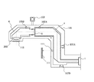
図1は、本発明の露光装置の実施形態を示す全体構成図である。
【0045】
図中、露光装置の光源であるレーザー装置1は、露光装置とは別に床または階下に設置されている。レーザー装置1は、波長160nm以下の波長域の真空紫外光を生成するエキシマレーザー装置である。本実施例では、157nm付近の発振波長を有するF2エキシマレーザーを用いるが、他に126nm付近の発振波長を有するAr2レーザー等の紫外線領域の波長を発する光源を用いても良い。
【0046】
レーザー装置1から射出したレーザービームは、ミラー2、3を介して装置本体に導入される。チャンバー4は、ミラー2、3を含む光路周辺を外気との通気から遮断するため、密閉構造となっている。チャンバー4からの光射出部には、ガラス5が配置されている。このガラス5は、チャンバー4の内側から照射されるレーザー装置1からのレーザービームを透過させ、レーザービームを後述する筐体6に導入する。また、ガラス5は、チャンバー4を、密閉状態を確保して保持されている。
【0047】
ガラス5は、フッ素化合物からなるガラス材で、具体的には螢石(CaF2)、フッ化マグネシウム(MgF2)、フッ化バリウム(BaF2)、SrF2、フッ素ドープ石英のいずれを使用してもよい。これらのガラス材は、157nm以下の波長の光に対して高い透過率を示すものである。
なお、チャンバー4内の詳細については後述する。
【0048】
ガラス5を透過した光は、筐体6に入射し、筐体6内のミラー7を介してレチクル8を照明する。
【0049】
この筐体6内の詳細についても後述する。
【0050】
レチクル8は、レチクルステージ9に載置したレチクル保持器10に載置される。レチクルステージ9は、不図示のレチクルステージ駆動ユニットにより、光軸と直交面内方向であって走査方向であるY方向に駆動される。バーミラー11は、レチクルステージ9に固定され、干渉計12によりバーミラー位置を計測し、レチクルステージの位置を計測する。本図においては、干渉計12が、1つのみ記載され、走査方向である図中座標Y方向に駆動される状態を示しているが、図中座標X方向にも干渉計とバーミラーを配置し、レチクルステージのXY二軸の位置の計測を行っても良い。
【0051】
レチクル8に描かれたパターン(不図示)は、投影光学ユニット13により所定の倍率で縮小されて、感光材を塗布したウエハ14に露光転写される。この投影光学ユニット13内の詳細についても後述する。
【0052】
ウエハ14は、ウエハステージ15に載置したウエハーチャック16に載置されている。ウエハステージ15は、不図示のウエハステージ駆動ユニットにより、光軸と直交面内方向であるXY方向に駆動される。バーミラー17は、ウエハステージに固定され、干渉計18によりバーミラー位置を計測し、ウエハステージの位置を計測する。本図においては、干渉計18が、1つのみ記載され、走査方向である図中座標Y方向に駆動される状態を示している。しかし、ウエハステージは、走査露光後、ウエハをX方向にステップ移動させる必要があるので、図中座標X方向にも干渉計とバーミラーを配置し、ウエハステージのXY二軸の位置の計測を行う。
【0053】
次に、装置構造体について述べる。
【0054】
主定盤20は、複数配置された脚19に載置される。主定盤20上には、ステージ定盤21及び鏡筒定盤22が載置される。
【0055】
ステージ定盤21には、XY平面に平行な基準面が設けられている。前述のウエハステージ15は、この基準面沿ってXY方向に移動する。本実施例では、ウエハステージ15は、ステージ定盤21に対して、気体軸受を用いたガイドによって非接触に支持されている。なお、ウエハステージを支持するガイドは、気体軸受に限られず、ボールやローラを用いた転動型ガイド、あるいは摺動型ガイドを用いてもよい。
【0056】
鏡筒定盤22は、前述の投影光学ユニット13、干渉計18のほかに、空調ダクト23および外筒24を載置している。干渉計18は、投影光学ユニット13を支持する鏡筒定盤22に支持されるため、投影光学ユニット13を基準としてウエハステージ15の位置を計測することができる。空調ダクト23は、後述の循環ユニットからの気体を内部のULPAフィルター23'(Uitra Low Penetration Air-filter)を介して、投影光学ユニット13の光軸と直交方向に吹きつけるものである。空調ダクト23は、干渉計18の干渉計光路18'およびウエハ14、さらに鏡筒定盤22に略囲われた空間を所定温度で安定させる。これにより、干渉計光路18'のゆらぎの低減と空間内の温度変化による物体変形の低減を達成する。また、空調ダクト23は、投影光学ユニット13の終端からウエハ14までの露光光路における光吸収物質(例えば酸素)の濃度の低減をはかっている。
【0057】
また、前述のレチクルステージ9は、外筒24に設けられた基準面に沿って走査方向であるY方向(および場合によってはX方向にも)移動する。本実施例では、レチクルステージ15は、外筒24に対して、気体軸受を用いたガイドによって非接触に支持されている。なお、レチクルステージを支持するガイドは、気体軸受に限られず、ボールやローラを用いた転動型ガイド、あるいは摺動型ガイドを用いてもよい。
【0058】
外筒24は、投影光学ユニット13の鏡筒定盤22上面より上部を囲い、露光光束が通過するよう上部に開口部24'を備えている。さらに、外筒24は、前述のレチクルステージ9のほか、干渉計12および空調ダクト25および筐体6(図中筐体6と外筒接合部は破断線にて省略)を載置している。干渉計12は、投影光学ユニット13と一体的に設けられた外筒24に支持されるため、投影光学ユニット13を基準としてレチクルステージ9の位置を計測することができる。空調ダクト25は、後述の循環ユニットからの気体を内部のULPAフィルター25'を介して投影光学ユニット13の光軸と直交方向に吹きつけるものである。空調ダクト25は、干渉計12の干渉計光路12'およびレチクル8、さらにレチクル周辺空間を所定温度で安定させる。これにより、干渉計光路12'のゆらぎの低減とレチクル周辺空間内の温度変化による物体変形の低減を達成する。また、空調ダクト25は、レチクル8前後の光路における光吸収物質(例えば酸素)の濃度の低減をはかっている。
【0059】
チャンバー26は、本実施例においては、装置本体を内部に収納し、外気との通気を遮断する密閉構造となっている。可動部材27は、ステンレス製ベローズなどからなり、脚19付近とチャンバー26を連結し、チャンバー26の密閉性を確保し、脚19や主定盤20との相対変位を吸収できる構造となっている。
【0060】
また、可動部材28は、ステンレス製ベローズなどからなり、チャンバー4とチャンバー26を連結し、チャンバー4とチャンバー26の密閉性を確保し、支持台30に載置したチャンバー4とチャンバー26の相対変位を吸収できる構造となっている。
【0061】
さらに、可動部材29は、ステンレス製ベローズなどからなり、チャンバー4と筐体6を連結し、チャンバー4と筐体6の密閉性を確保し、チャンバー4と筐体6の相対変位を吸収できる構造となっている。
【0062】
なお、可動部材27、28、29は、本実施例においてはステンレス製ベローズを用いるが、密閉性を確保し、相対変位を吸収できる構造であればこれに限るものではなく、ニッケル合金やチタン製の金属ベローズでもよいし、樹脂製ベローズであってもよい。さらにはベローズ以外に、磁性流体シールを用いてもよい。
【0063】
ロードロック室31は、レチクル8を搬入または搬出する際に用いるロードロック室であって、不図示の駆動ユニットによる開閉自在のゲートバルブ32、33を備えている。支持台34は、レチクル8の支持台である。レチクル搬送ロボット35は、レチクル保持器10へのレチクルの供給および回収を行う。
【0064】
ロードロック室36は、ウエハ14を搬入または搬出する際に用いるロードロック室であり、不図示の駆動ユニットによる開閉自在のゲートバルブ37、38を備えている。支持台39は、ウエハ14の支持台である。ウエハ搬送ロボット40は、ウエハチャック16へのウエハの供給および回収を行う。
【0065】
次に、チャンバー4、26及びロードロック室31、36内の環境制御、温度制御方法について説明する。
【0066】
ガス供給源51は、不活性ガスとしての窒素ガスまたはヘリウムガスのいずれかを供給する。この2種類のガスについては、F2レーザーの光に対して良好な透過率を示すものである。ガス供給源51は、実質的に酸素を含まないガスを供給する。なお、ここで、「実質的に酸素を含まない」とは、装置の性能に大きく影響を与える程度の酸素を含まないという意味であり、少なくともチャンバー4等に求められる酸素濃度より低い酸素濃度を意味する。
【0067】
ガス供給源51からのガスは、配管52を介して、チャンバー4の光源側の一端に設けられたガス供給口53に導かれ、チャンバー4内を経由した後、チャンバー4の露光装置側の他端に設けられたガス排出口54から排出され、配管55を介して、排気機構56に排気される。
【0068】
次に、チャンバー4内のガス流路を図2を用いて説明する。図1と同じ要素については同じ番号を付け、説明は省略する。
【0069】
レーザー装置1から射出されたレーザービームは、ミラー2によって反射され、ビーム成形光学ユニット201により所定のビーム形状に整形たれる。その後、レーザービームは、集光レンズ204及び207によって、所定の倍率でオプティカルインテグレータ210を照射する。オプティカルインテグレータ210は、微小レンズを二次元的に配列したものであって、集光レンズ213を介して、レチクル8(図1)との共役面219を重畳照明する。
【0070】
なお、ビーム整形光学ユニット201は、通気孔203を備えた支持台202に支持されている。集光レンズ204は、通気孔206を備えた支持台205に支持されている。集光レンズ207は、通気孔208を備えた支持台209に支持されている。オプティカルインテグレータ210は、通気孔212を備えた支持台211に支持されている。集光レンズ213は、通気孔215を備えた支持台214に支持されている。
【0071】
ガス供給口53からの気体は、チャンバー4内を光路に沿って流れ、通気孔203、206、208、212、215、218を順次経由してガス排出口54から排出される。
【0072】
チャンバー4内のガス流路の概念を図2中に矢印で示す。
【0073】
チャンバー4内の光学素子間の空間を順次経由する流路を備えることで、各光学素子間の空間の雰囲気を効率よくガス置換することができる。
【0074】
なお、本実施例においては、ガラス5は、平行平面板を用いているが、これに限られるものではなく、レンズやプリズムなど他の透過素子であってもよい。さらに本実施例においては、オプティカルインテグレータとしてハエノ目を用いた場合について説明しているが、他にロッドインテグレータを用いたり、ハエノ目を直列に複数個使用したり、あるいはハエノ目とロッドインテグレータを組合わせて使用した光学ユニットであってもよい。
【0075】
なお、チャンバー4内の光学ユニットは、後述の筐体6内の光学ユニットと合わせて、レチクルを照明する照明光学ユニットを形成している。
【0076】
さらに図1に戻り、本実施形態の露光装置の説明を続ける。
【0077】
図1において、ガス供給源57は、窒素ガスまたはヘリウムガスのいずれかのガスを供給する。
【0078】
ガス供給源57からのガスは、配管58を介して、筐体6またはベローズ29に設けられたガス供給口59に導かれ、筐体6内を経由した後、筐体6の一端に設けられたガス排出口60からチャンバー6内に排出される。
【0079】
筐体6内のガス流路を図2を用いて説明する。図1と同じ要素については同じ番号を付け、説明は省略する。
【0080】
マスキングブレード301は、レチクル8の照明範囲を規定する矩形状の開口を有する。また、矩形状の開口寸法は、レチクルパターン及びレチクル8の位置に応じて不図示の駆動手段により駆動されることで、変更可能である。マスキングブレード301の上記矩形開口を形成する遮光板301'は、前述のレチクル8との共役面219近傍に配置されている。集光レンズ302、305は、マスキンブブレード301で形成される矩形開口部の像を所定の倍率でレチクル8に投影する。
【0081】
従って、上述のごとく、筐体6内の光学ユニットは、チャンバー4内の光学ユニットと共に、レチクル8を照明する照明光学ユニットの一部を形成している。
【0082】
なお、遮光板301'は、不図示のガイドに沿って移動する構造であり、本実施例では非接触軸受である気体軸受を用いた場合について述べるが、これに限られるものではなく、ボールやローラを用いた転動型ガイド、あるいは摺動型ガイドを用いてもよい。
【0083】
集光レンズ302は、通気孔303を備えた支持台304に支持され、集光レンズ305は支持台306に支持されている。
【0084】
なお、ガス供給口59からの気体は、筐体6内を光路に沿って流れ、支持台4に設けられた通気孔303を経由して集光レンズ302と305の間の光路を経由後、ガス排出口60から排出される。筐体6内のガス流路の概念を図2中に矢印で示す。筐体6内の光学素子間を順次経由する流路を備えることで、光学素子間の雰囲気を効率よくガス置換することができる。
【0085】
また、本実施例においては、ガス排出口60から排出されるガスをチャンバー26内に直接流しているが、これに限られるものではない。筐体6からウエハ14までの光路に配置される光学ユニット、例えば投影光学ユニット13などにガス排出口60からのガスを導き、投影光学ユニット内を経由後、チャンバー26内に排出してもよい。または、ガス排出口60から排出されるガスを直接回収しても良い。
【0086】
なお、図2に示した筐体6内の光学ユニットは集光レンズユニットを用いた結像光学ユニットであるが、他に反射屈折型光学ユニットあるいは反射型光学ユニットを用いてもよい。
【0087】
さらに、マスキングブレード301の開口形状は、本実施例においては矩形を使用した場合について説明したが、他に所定の曲率を持った円弧状の開口であってもよい。
【0088】
また、本実施例においては、ガス供給口59は、筐体6の光源側の一端に設けられており、ガス排出口60は、筐体6のレチクル側の一端に設けられているが、これに限られるものではない。例えば、ガス供給口を筐体6のレチクル側の一端に設け、ガス排出口を筐体6の光源側の一端に設けても良い。特に、可動体であるマスキングブレードのある方を下流側としたほうが、筐体6内の雰囲気のガス純度等を考慮すると、望ましい場合がある。
【0089】
上述のガスの循環方法は、露光中におけるチャンバー4内および筐体6内の気体の置換方法である。しかし、露光前は、チャンバー4内および筐体6内の雰囲気は大気であるので、単に不活性ガスを流すだけでは、光路中の酸素濃度が低下するまでに時間がかかる。
【0090】
そこで、本発明では、チャンバー4内および筐体6内に不活性ガスを供給する前に、一度または複数回に分けてチャンバー4内および筐体6内の真空引きを行い、内部に最初に存在していた大気を排出する。
【0091】
ここで、例えばチャンバー4が真空引きされたときに、チャンバー4の内外の圧力差によってチャンバー4が変形すると、チャンバー4が保持している光学素子の位置がずれてしまい、望ましくない。
【0092】
そこで、本発明では、チャンバー4および筐体6の内外の圧力差を減少させるため、チャンバー4および筐体6をさらに密閉容器で囲んでいる。そして、チャンバー4内および筐体6内の真空引きを行うときに、密閉容器の内部もチャンバー4内および筐体6内の圧力と同じ程度の圧力になるように制御する。これによって、チャンバー4や筐体6の内外の圧力差を減少させ、チャンバー4や筐体6の真空引きの際の変形を抑えることができる。
【0093】
図3を用いて、上記の密閉容器の説明を行う。
【0094】
同図において、密閉容器101は、照明光学ユニットを有するチャンバー4と筐体6とを囲んでいる。真空ポンプ103は、密閉容器101内の気体を強制排気し、密閉容器101の真空引きを行う。
【0095】
通気孔105Aは、チャンバー4内部の雰囲気と密閉容器内の雰囲気とを連通している。真空ポンプ103が密閉容器101の気体を強制排気すると、密閉容器101内部が減圧雰囲気となり、チャンバー4内の気体が通気孔105Aを通じて密閉容器101中に排出される。これにより、チャンバー4内を真空引きすると共に、チャンバー4内部の圧力と密閉容器内の圧力をほぼ同程度のものとすることができる。
【0096】
通気孔105Bは、筐体6内部の雰囲気と密閉容器内の雰囲気とを連通している。真空ポンプ103が密閉容器101の気体を強制排気すると、密閉容器101内部が減圧雰囲気となり、筐体6内の気体が通気孔105Bを通じて密閉容器101中に排出される。これにより、筐体6内を真空引きすると共に、筐体6内部の圧力と密閉容器内の圧力をほぼ同程度のものとすることができる。
【0097】
上記の構成により、チャンバー4内と筐体6内の真空引きを行うと共に、チャンバー4と筐体6内外の圧力差を減少させることができる。これにより、真空引きした際のチャンバー4と筐体6の変形を軽減することができる。
【0098】
なお、図3では、チャンバー4と筐体6とを同一の密閉容器で囲んでいるが、これに限るものではなく、それぞれ別の密閉容器に囲んでも良い。また、密閉容器101を前述のチャンバー26と兼用するようにしても良い。
【0099】
ここで、密閉容器101を真空引きすると、密閉容器101の内外で圧力差が生じ、変形するおそれがある。密閉容器101が、例えばチャンバー4を支持しているとすると、この密閉容器101の変形がチャンバー4に伝達されることは望ましくない。そこで、本発明では、密閉容器101とチャンバー4との間に変位を発生する変位機構を設けている。
【0100】
変位機構107A、107Bは、密閉容器101が、変形したときに、その変形がチャンバー4に伝達されないように、密閉容器の変形に応じて密閉容器101とチャンバー4との間で変位を発生させる。外部に設けられた基準部材111を照明光学ユニットの位置決めの基準とし、チャンバー4と基準部材111との距離を干渉計113によって検出する。干渉計113により検出された位置情報の基づいて、変位機構107A、107Bを制御する。
【0101】
なお、変位機構107A、107Bは、チャンバー4を6軸方向に制御できることが望ましい。また、変位機構107A、107Bは、密閉容器に対するチャンバー4の支持も行ってよい。また、変位機構107A、107Bは、非接触で変位を与えられるものが望ましい。
【0102】
なお、図3では、変位機構はチャンバー4にしか描かれていないが、筐体6にも同様に設けられる。
【0103】
また、密閉容器101は、露光の際に露光光を通す必要がある。そこで、本発明では、密閉容器101に透過窓115を設けている。透過窓115は、密閉容器101内の密閉性を確保するように保持されるとともに、密閉容器の内外に圧力差があっても耐えられる構造となっている。なお、透過窓115は、フッ素化合物からなるガラス材で、具体的には蛍石(CaF2)、フッ化マグネシウム(MgF2)、フッ化バリウム(BaF2)、SrF2、フッ素ドープ石英のいずれを使用しても良い。これらのガラス材は、157nm以下の波長の光に対して高い透過率を示すものである。また、本実施例においては、透過窓115は、平行平面板を用いているが、これに限られるものではなく、レンズ、プリズム、膜など他の透過素子であっても良い。
【0104】
上記のようにチャンバー4内と筐体6内の真空引きを行い、チャンバー4内と筐体6内に最初に存在していた大気を排出した後は、前述した通り、ガス供給口53やガス供給口59に不活性ガスを供給し、チャンバー4内と筐体6内の雰囲気を循環させる。このときは、通気孔105A、105Bは閉じられ、図2で述べたガスの経路が確保されるようにする。
【0105】
なお、密閉容器内を真空引きすると、透過窓115が歪んだり、位置ずれを起こしたりするおそれがある。そこで、透過窓115はベローズ(可動体)で密閉容器に対して保持され、不図示のアクチュエータで密閉容器に対して移動可能であってもよい。ここで、透過窓のベローズは、後述する投影光学ユニットについての透過窓165のべローズとほぼ同様である。
【0106】
なお、図3では、通気孔105A、105Bにより、密閉容器101内とチャンバー4、筐体6内との圧力差を軽減していた。しかし、圧力差を軽減するための手段はこれに限られるものではない。例えば、図4に示されるように、密閉容器101、チャンバー4および筐体6にそれぞれ真空ポンプ103A、103B、103Cを設け、それぞれの内部圧力を計測して計測結果に基づいて、それぞれの真空ポンプを制御しても良い。また、後述の図6のように、チャンバー4や筺体6に真空ポンプを設け、チャンバー4と密閉容器101の間や筐体6と密閉容器101の間に通気孔を設けるようにしても良い。
【0107】
また、図3において、露光時のチャンバー4内や筐体6内の圧力が、外部の圧力とほぼ同じ場合、密閉容器101の密閉性を保つ必要はなくなる。このような場合は、密閉容器101に設けられる透過窓115は特に必要はなく、例えば真空引き時に閉じられる開閉扉であっても良い。
【0108】
また、図3において、露光時はチャンバー4内と筐体6内の不活性ガスの純度は特に高める必要がある。そのため、露光時のチャンバー4内と筐体6内の圧力を陽圧としても良い。これにより、チャンバー4や筐体6の外部から流入するガスを防ぎ、チャンバー4と筐体6の内部の不活性ガスの純度を維持することができる。この際、密閉容器101内部の雰囲気も不活性ガスの雰囲気とすれば、密閉容器101からチャンバー4や筐体6内にガスが流入しても、チャンバー4や筐体6のガスの純度の低下を軽減することができる。そのため、密閉容器101に不活性ガスの供給口や排出口を設けることが望ましい。
【0109】
なお、上記のように、密閉容器101内を不活性ガスで満たすとしても、チャンバー4や筐体6の内部ほどの純度が望まれるわけではない。例えば、チャンバー4(若しくは筐体6)内、密閉容器101内、密閉容器外部、の順に純度を高くしても良い。
【0110】
また、上記のように、チャンバー4内や筐体6内の圧力を陽圧とする場合、例えば、チャンバー4(若しくは筐体6)内、密閉容器101内、密閉容器外部、の順に圧力を高くするように制御しても良い。
【0111】
なお、チャンバー4内や筐体6内を複数回に分けて真空引きする場合、真空引き工程の間に、チャンバー4内や筐体6内を不活性ガスで満たす工程があることが望ましい。複数回に分けて真空引きすることにより、各真空引き工程時の内外圧力差を軽減させ、変形を軽減することができる。また、短時間で酸素濃度を十分に下げることができる。
【0112】
図1に戻り、説明を続ける。図1において、ガス供給源57からのガスは、配管61を介して、投影光学ユニット13のウエハ側の一端に設けられたガス供給口62に導かれ、投影光学ユニット13内を経由した後、投影光学ユニット13のレチクル側の他端に設けられたガス排出口63からチャンバー26内に排出される。
【0113】
投影光学ユニット13内のガス流路を図5を用いて説明する。図1と同じ要素については同じ番号を付け、説明は省略する。
【0114】
レチクル8に描かれたパターンは、レンズ402、405、408、411、414、417、420により、ウエハ14に縮小投影される。401は、上記レンズ群の鏡筒である。
【0115】
レンズ402は、ガス排出口63を備えた支持台404に支持されている。レンズ405は、通気孔406を備えた支持台407に支持されている。レンズ408は、通気孔409を備えた支持台410に支持されている。レンズ411は、通気孔412を備えた支持台413に支持されている。レンズ414は、通気孔415を備えた支持台416に支持されている。レンズ417は、通気孔418を備えた支持台419に支持されている。レンズ420及び上記支持台407、407、410、413、416、419は、鏡筒401に支持されている。
【0116】
ガス供給口62からの気体は、各支持台に設けられた通気口418、415、412、409、406を順次経由して、ガス排出口63から排出される。投影光学ユニット13内のガス流路の概念を図4中に矢印で示す。投影光学ユニット13内の光学素子間を順次経由する流路を備えることで、投影光学ユニット13内の光学素子間の雰囲気を効率よくガス置換することができる。
【0117】
なお、本実施例においては、ガス排出口63から排出されるガスをチャンバー26内に直接流しているが、これに限られるものではない。ガラス5(図1〜4)からウエハ14までの光路に配置される光学ユニット、例えば筐体6(図1、図4)などにガス排出口63からのガスを導き、筐体6内を経由後、チャンバー26内に排出してもよい。または、ガス排出口63から排出されるガスを直接回収しても良い。
【0118】
また、本実施例においては、投影光学ユニット13は、屈折型光学ユニットを用いているが、他に反射屈折型光学ユニットあるいは反射型光学ユニットを用いてもよい。
【0119】
上述のガスの循環方法は、露光中における投影光学ユニット13内の気体の置換方法である。しかし、露光前は、投影光学ユニット13内の雰囲気は大気であるので、単に気体を流すだけでは、光路中の酸素濃度が低下するまでに時間がかかる。
【0120】
そこで、本発明では、投影光学ユニット13内に不活性ガスを供給する前に、一度または複数回に分けて投影光学ユニット13内の真空引きを行い、内部に最初に存在していた大気を排出する。
【0121】
ここで、投影光学ユニット13が真空引きされたときに、投影光学ユニット13の内外の圧力差によって投影光学ユニット13が変形すると、投影光学ユニットのレンズの位置がずれてしまい、望ましくない。
【0122】
そこで、本発明では、投影光学ユニット13の内外の圧力差を減少させるため、投影光学ユニット13をさらに密閉容器で囲んでいる。そして、投影光学ユニット13内の真空引きを行うときに、密閉容器の内部も投影光学ユニット13内の圧力と同じ程度の圧力になるように制御する。これによって、投影光学ユニット13の内外の圧力差を減少させ、投影光学ユニット13の真空引きの際の変形を抑えることができる。
【0123】
図6を用いて、上記の密閉容器の説明を行う。同図において、密閉容器151は、投影光学ユニット13を囲んでいる。真空ポンプ153は、密閉容器151内の気体を強制排気し、密閉容器101の真空引きを行う。
【0124】
通気孔155は、投影光学ユニット13の内部の雰囲気と密閉容器151内の雰囲気とを連通している。真空ポンプ153が投影光学ユニット13の気体を強制排気すると、投影光学ユニット13内部が減圧雰囲気となり、密閉容器151内の気体が通気孔155を通じて投影光学ユニット13を介して排出される。これにより、投影光学ユニット13内および密閉容器151内を真空引きすると共に、投影光学ユニット13内部の圧力と密閉容器151内の圧力をほぼ同程度のものとすることができる。
【0125】
上記の構成により、投影光学ユニット13内の真空引きを行うと共に、投影光学ユニット13の内外の圧力差を減少させることができる。これにより、真空引きした際の投影光学ユニット13の変形を軽減することができる。
【0126】
なお、密閉容器151は、前述のチャンバー26または外筒24等と兼用するようにしても良い。
【0127】
ここで、密閉容器151を真空引きすると、密閉容器151の内外で圧力差が生じ、変形するおそれがある。密閉容器151が、投影光学ユニット13を支持しているとすると、この密閉容器151の変形が投影光学ユニット13に伝達されることは望ましくない。そこで、本発明では、密閉容器151と投影光学ユニットとの間に変位を発生する変位機構を設けている。
【0128】
変位機構157A、157Bは、密閉容器151が、変形したときに、その変形が投影光学ユニット13に伝達されないように、密閉容器151の変形に応じて密閉容器151と投影光学ユニット13との間で変位を発生させる。外部に設けられた基準部材111を投影光学ユニット13の位置決めの基準とし、投影光学ユニット13と基準部材111との距離を干渉計163によって検出する。干渉計163により検出された位置情報の基づいて、変位機構157A、157Bを制御する。
【0129】
なお、変位機構157A、157Bは、投影光学ユニット13を6軸方向に制御できることが望ましい。また、変位機構157A、157Bは、密閉容器151に対する投影光学ユニット13の支持も行ってよい。また、変位機構157A、157Bは、非接触で変位を与えられるものが望ましい。
【0130】
また、密閉容器151は、露光の際に露光光を通す必要がある。そこで、本発明では、密閉容器151に透過窓165A、165Bを設けている。透過窓165A、165Bは、密閉容器151内の密閉性を確保するように保持されるとともに、密閉容器151の内外に圧力差があっても耐えられる構造となっている。
また、密閉容器151の変形を考慮して、後述の図7のように、透過窓をベローズで保持して、アクチュエータで移動可能としてもよい。なお、透過窓165A、165Bは、フッ素化合物からなるガラス材で、具体的には蛍石(CaF2)、フッ化マグネシウム(MgF2)、フッ化バリウム(BaF2)、SrF2、フッ素ドープ石英のいずれを使用しても良い。これらのガラス材は、157nm以下の波長の光に対して高い透過率を示すものである。また、本実施例においては、透過窓165A、165Bは、平行平面板を用いているが、これに限られるものではなく、レンズ、プリズム、膜など他の透過素子であっても良い。
【0131】
上記のように投影光学ユニット13内の真空引きを行い、投影光学ユニット13内に最初に存在していた大気を排出した後は、前述した通り、ガス供給口62に不活性ガスを供給し、投影光学ユニット13内の雰囲気を循環させる。このときは、通気孔155は閉じられ、図5で述べたガスの経路が確保されるようにする。
【0132】
なお、図6では、通気孔155により、密閉容器151内と投影光学ユニット13内との圧力差を軽減していた。しかし、圧力差を軽減するための手段はこれに限られるものではない。例えば、図4の場合と同様に、密閉容器151と投影光学ユニット13のそれぞれに真空ポンプ153A、153Bを設け、それぞれの内部圧力を計測して計測結果に基づいて、それぞれの真空ポンプを制御しても良い。または、前述の図3の場合と同様に、密閉容器に真空ポンプを設け、投影光学ユニットと密閉容器の間に通気孔を設けるようにしても良い。
【0133】
また、図6において、露光時の投影光学ユニット13の圧力が、外部の圧力とほぼ同じ場合、密閉容器151の密閉性を保つ必要はなくなる。このような場合は、密閉容器151に設けられる透過窓165A、165Bは特に必要はなく、例えば真空引き時に閉じられる開閉扉であっても良い。
【0134】
また、図6において、露光時は投影光学ユニット13内の不活性ガスの純度は特に高める必要がある。そのため、露光時の投影光学ユニット13内の圧力を陽圧としても良い。これにより、投影光学ユニット13の外部から流入するガスを防ぎ、投影光学ユニット3の内部の不活性ガスの純度を維持することができる。この際、密閉容器151内部の雰囲気も不活性ガスの雰囲気とすれば、密閉容器151から投影光学ユニット13内にガスが流入しても、投影光学ユニット13内のガスの純度の低下を軽減することができる。そのため、密閉容器151に不活性ガスの供給口や排出口を設けることが望ましい。
【0135】
なお、上記のように、密閉容器151内を不活性ガスで満たすとしても、投影光学ユニット13の内部ほどの純度が望まれるわけではない。例えば、投影光学ユニット13内、密閉容器151内、密閉容器外部、の順に純度を高くするようにしても良い。
【0136】
また、上記のように、投影光学ユニット13内の圧力を陽圧とする場合、例えば、投影光学ユニット13内、密閉容器101内、密閉容器外部、の順に圧力を高くするように制御しても良い。
【0137】
なお、投影光学ユニット13内を複数回に分けて真空引きする場合、真空引き工程の間に、投影光学ユニット13内を不活性ガスで満たす工程があることが望ましい。複数回に分けて真空引きすることにより、各真空引き工程時の内外圧力差を軽減させ、変形を軽減することができる。また、短時間で酸素濃度を十分に下げることができる。
【0138】
次に、図7を用いて、投影光学ユニットを覆う密閉容器の変形例の説明を行なう。同図において、図6と同じ要素については同じ番号を付け、説明を省略する。
【0139】
同図において、投影光学ユニット13は、鏡筒定盤22に支持されている。また、密閉容器151Aは、投影光学ユニット13の鏡筒定盤22より上側を覆っている。また、密閉容器151Bは、投影光学ユニット13の鏡筒定盤22より下側を覆っている。図には示されていないが、密閉容器151A内部の空間と密閉容器151B内部の空間は、連通している。
【0140】
真空ポンプ153Aは、密閉容器151A、151Bと投影光学ユニット13との間の空間を真空引きする。また、真空ポンプ153Bは、投影光学ユニット13内の気体を真空引きする。これにより、投影光学ユニット13の内部の圧力と密閉容器151内の圧力をほぼ同程度のものとすることは、前述の場合と同様である。なお、通気孔を設け、いずれかに真空ポンプを設けても良いのも、前述の場合と同様である。
【0141】
ここで、密閉容器151A、151Bを真空引きすると、密閉容器151A、151Bの内外で圧力差が生じ、変形するおそれがある。この密閉容器151A、151Bの変形の影響が投影光学ユニット13に伝達されることは望ましくない。
【0142】
そこで、図7の例では、密閉容器151Aと鏡筒定盤22は、可動体であるステンレス製ベローズ167Aを介して密閉性を保って連結されている。同様に、密閉容器151Bは、可動体であるステンレス製ベローズ167Bを介して密閉性を保って連結されている。これにより、密閉容器151A、151Bの内外の圧力差により、密閉容器151A、151Bが変形しても、変形の影響が鏡筒定盤に伝わらないようになっている。従って、密閉容器151A、151Bの変形の影響が投影光学ユニット13に伝わることはない。なお、鏡筒定盤22は、密閉容器151A、151Bの内部を減圧にしても、変形は起きにくい。よって、密閉容器151A、151B内部を真空引きしたとしても、投影光学ユニット13が受ける変形の影響は軽減される。
【0143】
なお、密閉容器151A、151Bの変形により、密閉容器に設けられた透過窓165A、165Bが歪んだり、位置ずれを起こしたりするおそれがある。そこで、透過窓165A、165Bは、ベローズ(可動体)169A、169Bでそれぞれ密閉容器151A、151Bに対して移動可能に保持され、アクチュエータ(不図示)により密閉容器に対して移動可能となっている。密閉容器151A、151Bが変形を起こしたときは、アクチュエータによって透過窓165A、165Bを投影光学ユニット13に対して所定の位置関係になるように位置決めする。なお、透過窓165A、165Bの保持は、ベローズに限るものではなく、透過窓165A、165Bを密閉容器151A、151Bに対して移動可能に保持し、密閉容器内の気密性を保てるものであればなんでも良い。
【0144】
なお、透過窓165A、165Bの代わりに、前述の開閉扉を設ける場合は、上記のベローズ169A、169Bが必要でないことは言うまでもない。
【0145】
再び、図1に戻り、説明を続ける。
【0146】
ガス排出口60、63からチャンバー26内に排出されたガスは、チャンバー26の循環出口70から排出され、配管71を介して、気体循環ユニット72の導入口73に導かれる。気体循環ユニット72内で所定の流量に配分されたガスは、気体循環ユニット72の分配口74a、74b、74c、74dからそれぞれ排出される。
【0147】
分配口74aから排出されたガスは、配管75aを介して、チャンバー26内のほぼ全体のガスをダウンフローにさせるダウンフローダクト76に導かれ、ダウンフローダクト76内のULPAフィルター76'を介してチャンバー26内に吹き出される。
【0148】
分配口74bから排出されたガスは、配管75bを介して、部分ダクト25に導かれ、前述のごとくレチクル8及び干渉計光路12'近傍の空間に吹きつけられる。
【0149】
分配口74cから排出されたガスは、配管75cを介して、外筒24の気体導入口41に導かれ、投影光学ユニット13と外筒24との間の空間を経由した後、外筒24の開口部24'からチャンバー26内に排出される。
【0150】
分配口74dから排出されたガスは、配管75dを介して、部分ダクト23に導かれ、前述のごとくウエハ14及び干渉計光路18'近傍の空間に吹きつけられる。
【0151】
なお、不図示であるが、気体循環ユニット72内部では、導入口からのガス中の不純物を取り除くためのケミカルフィルタが備えられている。
【0152】
また、気体循環ユニット72内部には、不図示の温調装置が設けられている。温調装置は、露光装置内部に設けられた温度計77a〜77dの検出結果に基づき、制御装置78の指令により所定温度に制御する。
【0153】
なお、前述のガス供給源57からのガスは、予めガス供給源57内で所定温度に制御されてもよいし、配管58、61が上述のごとく温度制御された空間を経由してガス供給口59、62に到達する間に所定温度になるよう配管経路を決定してもよい。
【0154】
図1において、高圧ガス供給装置79は、チャンバー26内のガスの一部を配管80にて回収し、所定のガス圧力に上昇させた後、配管81aを介してウエハーステージ15の気体軸受(不図示)へ、配管81bを介してレチクルステージ9の気体軸受(不図示)へ、そして配管81cを介してマスキングブレード301(図4)の気体軸受(不図示)へそれぞれ供給する。チャンバー26内のパージガスである不活性ガスを気体軸受の作動流体として用いることで、チャンバー26内の環境は、所定の状態に維持することができる。
【0155】
次に、図8を用いて高圧ガス供給装置79の内部概略構成を以下に述べる。
【0156】
配管80からのガスの圧力を圧力ゲージ701で検出し、制御装置78(図1)でコントロールバルブ702を制御することで、所定流量に制御する。コントロールバルブで所定の流量に制御されたガスは、回収ポンプ703を通って、バッファータンク704によりガスが貯められ、そして圧縮機705にて所定圧力に加圧され、配管81a〜81cに流される。また、圧力ゲージ701とコントロールバルブ702の間でガス流路は分岐され、排気ポンプ706にて排気される。この排気量は、バッファータンク704に設けた圧力ゲージ707の検出結果に応じて、排気の必要が生じた時に、マスフローコントローラ708によって制御される。なお、マスフローコントローラ708は、圧力ゲージ707の検出結果により、制御装置78(図1)によって、制御される。
【0157】
上記構成によれば、チャンバー26内の気圧は、常に一定の圧力に制御することが可能である。これにより、気圧変動の影響を受けやすい光学特性、例えば投影光学ユニット13(図1)の性能の維持を可能にする。
【0158】
また、チャンバー26内の気圧と外気圧との相対圧力差を所定の値に維持することも可能である。この場合は、圧力ゲージ701を差圧計にして、配管80内(つまりチャンバー26内)の圧力と外気との圧力差を検出することで達成できる。
【0159】
さらに、チャンバー26内とチャンバー4内の相対気圧差を所定の値に維持することも可能である。この場合は、上述の差圧計で配管80内(つまりチャンバー26内)とチャンバー4内の相対気圧差を検出することで達成できる。
【0160】
また、チャンバー26に前述の密閉容器101や密閉容器151の機能を持たせても良い。
【0161】
図1において、ガス供給源57からのガスは、配管82を介して、ウエハ用のロードロック室36に供給され、内部を置換しながら配管83を介して排気機構86に排気される。同様に、ガス供給源57のガスは配管84を介してレチクル用のロードロック室31に供給され、内部を置換しながら配管85を介して排気機構86に排気される。
【0162】
なお、ガス供給のタイミングについては、ゲートバルブ32もしくは37が開けられ、レチクルやウエハが支持台34、39に載置された後、ゲートバルブ32,37が閉じられ、その後、ガス供給源に備えられたバルブ(不図示)と排気機構86内に備えられたバルブ(不図示)とを制御装置78の指令によって開放しておこなわれる。
【0163】
ロードロック室31、36内が所定の状態になったら制御装置78の指令によりバルブを閉じてガス供給を停止する。更に、ゲートバルブ33及び38を開け、搬送手段35及び40によりレチクル8及びウエハ14が装置内に搬入される。
【0164】
レチクル8もしくはウエハ14を装置外に搬出する場合は、ゲートバルブ32,33,37,38が閉じられた状態でガス供給が開始され、各々のロードロック室内が所定の状態に達した所でガス供給を停止する。次にゲートバルブ33、38を開け、搬送手段35、40にてレチクル8及びウエハ14を装置から搬出し、ロードロック室31、39内の支持台34、39に載置する。載置後、ゲートバルブ33,38は閉じられ、今度はゲートバルブ32、37を開けてレチクル8、ウエハ14を不図示の手段で取出す。
【0165】
上記説明においては、レチクル8とウエハ14の装置への搬入及び搬出を同時に述べたが、レチクル8とウエハ14の搬入、搬出を個別に行ってもよいのは言うまでもない。
【0166】
またロードロック室31、36をガス置換するのは、ゲートバルブ33,38を開けた時に、チャンバー26内の環境に影響を与えないようにするためのものであって、これは周知の通りである。
【0167】
さらに、レチクル8のパターン面へのゴミの付着防止の目的でペリクル(不図示)を使用する場合、レチクル8とペリクルとペリクルを支持するためのペリクルフレーム(不図示)とで囲まれた空間もパージガス置換するのが望ましく、均圧孔付ペリクルフレーム(ペリクルフレーム内外を連通させる通気孔付)を使用するのが望ましい。
【0168】
排気口87は、チャンバー26内のガスを排気するための排気口である。
【0169】
装置の運転を開始する際、チャンバー26内部及び気体循環ユニット72内は大気状態である。
【0170】
従って、装置立上げ時は、ガス供給源57から投影光学ユニット13及び筐体6へのガス供給を開始するとともに、排気口87から配管88を介して、排気機構86への排気も行う。この排気動作のON/OFFは、排気手段86内に備えたバルブ(不図示)を、制御装置78で制御することで行う。
【0171】
チャンバー26内及びこの循環ユニットが所定の置換状態に達したら、排気口87からの排気を停止し、露光動作可能状態になる。
【0172】
排気口87からの排気を停止するタイミングの判断は、排気開始から所定時間に達したかどうかで制御装置78が自動で判断して排気停止指令を送ってもよいし、チャンバー26内もしくはその循環ユニット内の所定箇所にガス検出計(不図示)を配置し、その検出結果に基づき制御装置78が自動で判断して排気停止指令を送ってもよい。
【0173】
また、装置の運転を開始する際に、チャンバー4及び26の置換状態をより短時間で所定状態にしたい場合、あるいはロードロック室31及び36内はレチクルやウエハ交換毎に大気開放と置換状態を繰り返すものであるため、より短時間で置換を終了しスループットを向上させる場合は、真空ポンプを用いて排気手段56、86から大気を強制排気して、チャンバー4,26内およびロードロック室31,36内を真空にした後に上述した方法でガスパージを行っても良い。この場合は、チャンバー4,26およびロードロック室31,36は、真空状態時における変形が装置性能に影響しないよう十分な剛性が必要となる。
【0174】
図1の実施例においては、可動部材27、28、29を用いているため、真空時にチャンバー4、26の変形が生じたとしても、隣接する構成要素の変形が直接伝わるのを防止している。
【0175】
なお、チャンバー内およびロードロック室内を真空状態にした後にガス供給するこの一連の動作は、必要であれば複数回繰り返してもよい。真空引きを1回のみ行ってパージする場合に比べて複数回繰り返せば、チャンバー内およびロードロック室内の到達真空度が相対的に低真空(絶対圧が高い)で済み、真空ポンプや真空対応部品のコストが大幅に軽減できる。本発明の置換方法では、最後の真空引きが終わってからヘリウムを導入することとし、その前のパージには窒素を用いることが望ましい。
【0176】
さらに、図1の実施形態によれば、チャンバー4内部をメンテナンス等で大気に開放する場合でも、チャンバー26側は、パージ状態を維持することが可能で、その反対にチャンバー26内部を大気開放する場合でもチャンバー4側は、パージ状態を維持することが可能である。
【0177】
<実施形態2>
図14は、本発明にかかる実施形態2を説明する図である。図14を用いて、照明光学ユニットを覆う密閉容器の変形例の説明を行なう。
【0178】
同図において、図3と同じ構成要素については同じ参照番号を付け、その説明は省略するものとする。
【0179】
同図において、照明光学ユニットを構成するチャンバー4及び筐体6は、照明ユニット定盤1022に支持されている。また、密閉容器101はチャンバー4及び筐体6を覆っている。
【0180】
真空ポンプ103Aは密閉容器101とチャンバー4及び筐体6との間の内部空間の気圧を真空にする。また、同様に真空ポンプ103Bはチャンバー4内部の気圧を真空にし、真空ポンプ103Cは筐体6内部の気圧を真空にする。これにより、チャンバー4及び筐体6の内部の圧力と密閉容器101内部の圧力をほぼ同程度のものとすることができる。
【0181】
なお、実施形態1で説明したように、チャンバー4と密閉容器101の間や、筐体6と密閉容器101との間に通気孔を設け、いずれかに真空ポンプを設けてるようにしてもよい。
【0182】
ここで、密閉容器101を真空引きすると、密閉容器101の内側と外側で圧力差が生じ、変形するおそれがある。この密閉容器101の変形の影響がチャンバー4または筐体6に伝達されることは望ましくない。そこで、図14の構成では、密閉容器101と照明ユニット定盤1022は、可動体であるステンレス製ベローズ1167を介して、圧力差により生じた変形を吸収することにより密閉性を保って連結されている。これにより、密閉容器101の内外の圧力差により、密閉容器101が変形しても、変形の影響が定盤に伝わらないようになっている。従って、密閉容器101の変形の影響がチャンバー4及び筐体6に伝わることはない。
【0183】
なお、照明ユニット定盤1022は、密閉容器101の内部を減圧にしても変形は起きにくいものであるので、密閉容器101内部を真空引きしたとしても、照明ユニット定盤1022がチャンバー4、筐体6に与える変形の影響は小さい。
【0184】
一方、密閉容器101の変形により、密閉容器に設けられた透過窓115が歪んだり、位置ずれを起こしたりするおそれがある。そこで、透過窓115は、可動体であるベローズ1169によりそれぞれ密閉容器101に対して移動可能に保持され、不図示のアクチュエータにより密閉容器に対して移動可能となっている。密閉容器101が、内外の圧力差により変形を起こしたときは、アクチュエータによって透過窓115を筐体6に対して所定の位置関係になるように位置決めすることが可能である。
【0185】
なお、透過窓115の保持は、ベローズに限るものではなく、透過窓115を密閉容器101に対して移動可能に保持し、密閉容器内の気密性を保つことが可能な部材であればよい。
【0186】
また、透過窓115の代わりに、実施形態1で説明したように真空引き時に負圧によって閉じるような開閉扉を設ける場合は、上記のベローズ1169は必要でないことは言うまでもない。
【0187】
また、図3に示すような基準部材111と定盤1022が剛に接続されている場合、図3における、変位機構107A、107Bによる位置決めは不要となる。
【0188】
本実施形態において、チャンバー4及び筐体6を保持する照明ユニット定盤1022は、前述の実施形態の投影光学ユニット13を保持する鏡筒定盤22(図7参照)と一体的に設けても良い。また、本実施形態の密閉容器101は、前述の実施形態の密閉容器151(図7参照)と同一の構成部材であっても良い。
【0189】
さらに、このようにチャンバーを密閉容器で囲む構成は、投影光学ユニットや照明ユニットに限られるものではない。例えば、ウエハステージ空間やレチクルステージ空間をチャンバーで囲み、このチャンバーを密閉容器で囲む構成であっても良い。そして、その密閉容器は、同一の構成部材であって良い。
【0190】
<半導体生産システムの実施例>
次に、半導体デバイス(ICやLSI等の半導体チップ、液晶パネル、CCD、薄膜磁気ヘッド、マイクロマシン等)の生産システムの例を説明する。これは半導体製造工場に設置された製造装置のトラブル対応や定期メンテナンス、あるいはソフトウェア提供などの保守サービスを、製造工場外のコンピュータネットワークを利用して行うものである。
【0191】
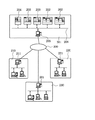
図9は全体システムをある角度から切り出して表現したものである。図中、1101は半導体デバイスの製造装置を提供するベンダー(装置供給メーカー)の事業所である。製造装置の実例として、半導体製造工場で使用する各種プロセス用の半導体製造装置、例えば、前工程用機器(露光装置、レジスト処理装置、エッチング装置等のリソグラフィ装置、熱処理装置、成膜装置、平坦化装置等)や後工程用機器(組立て装置、検査装置等)を想定している。事業所1101内には、製造装置の保守データベースを提供するホスト管理システム1108、複数の操作端末コンピュータ1110、これらを結んでイントラネットを構築するローカルエリアネットワーク(LAN)1109を備える。ホスト管理システム1108は、LAN1109を事業所の外部ネットワークであるインターネット1105に接続するためのゲートウェイと、外部からのアクセスを制限するセキュリティ機能を備える。
【0192】
一方、1102〜1104は、製造装置のユーザーとしての半導体製造メーカーの製造工場である。製造工場1102〜1104は、互いに異なるメーカーに属する工場であっても良いし、同一のメーカーに属する工場(例えば、前工程用の工場、後工程用の工場等)であっても良い。各工場1102〜1104内には、夫々、複数の製造装置1106と、それらを結んでイントラネットを構築するローカルエリアネットワーク(LAN)1111と、各製造装置1106の稼動状況を監視する監視装置としてホスト管理システム1107とが設けられている。各工場1102〜1104に設けられたホスト管理システム1107は、各工場内のLAN1111を工場の外部ネットワークであるインターネット1105に接続するためのゲートウェイを備える。
【0193】
これにより各工場のLAN1111からインターネット1105を介してベンダー1101側のホスト管理システム1108にアクセスが可能となり、ホスト管理システム1108のセキュリティ機能によって限られたユーザーだけがアクセスが許可となっている。具体的には、インターネット1105を介して、各製造装置1106の稼動状況を示すステータス情報(例えば、トラブルが発生した製造装置の症状)を工場側からベンダー側に通知する他、その通知に対応する応答情報(例えば、トラブルに対する対処方法を指示する情報、対処用のソフトウェアやデータ)や、最新のソフトウェア、ヘルプ情報などの保守情報をベンダー側から受け取ることができる。
【0194】
各工場1102〜1104とベンダー1101との間のデータ通信および各工場内のLAN1111でのデータ通信には、インターネットで一般的に使用されている通信プロトコル(TCP/IP)が使用される。なお、工場外の外部ネットワークとしてインターネットを利用する変わりに、第三者からのアクセスができずにセキュリティの高い専用線ネットワーク(ISDNなど)を利用することもできる。
【0195】
また、ホスト管理システムはベンダーが提供するものに限らずユーザーがデータベースを構築して外部ネットワーク上に置き、ユーザーの複数の工場から該データベースへのアクセスを許可するようにしてもよい。
【0196】
さて、図10は本実施形態の全体システムを図9とは別の角度から切り出して表現した概念図である。先の例ではそれぞれが製造装置を備えた複数のユーザー工場と、該製造装置のベンダーの管理システムとを外部ネットワークで接続して、該外部ネットワークを介して各工場の生産管理や少なくとも1台の製造装置の情報をデータ通信するものであった。これに対し本例は、複数のベンダーの製造装置を備えた工場と、該複数の製造装置のそれぞれのベンダーの管理システムとを工場外の外部ネットワークで接続して、各製造装置の保守情報をデータ通信するものである。
【0197】
図中、1201は製造装置ユーザー(半導体デバイス製造メーカー)の製造工場であり、工場の製造ラインには各種プロセスを行う製造装置、ここでは例として露光装置1202、レジスト処理装置1203、成膜処理装置1204が導入されている。なお図10では製造工場201は1つだけ描いているが、実際は複数の工場が同様にネットワーク化されている。
【0198】
工場内の各装置はLAN1206で接続されてイントラネットを構成し、ホスト管理システム1205で製造ラインの稼動管理がされている。一方、露光装置メーカー1210、レジスト処理装置メーカー1220、成膜装置メーカー1230などベンダー(装置供給メーカー)の各事業所には、それぞれ供給した機器の遠隔保守を行なうためのホスト管理システム1211,1221,1231を備え、これらは上述したように保守データベースと外部ネットワークのゲートウェイを備える。
【0199】
ユーザーの製造工場内の各装置を管理するホスト管理システム1205と、各装置のベンダーの管理システム1211,1221,1231とは、外部ネットワーク1200であるインターネットもしくは専用線ネットワークによって接続されている。このシステムにおいて、製造ラインの一連の製造機器の中のどれかにトラブルが起きると、製造ラインの稼動が休止してしまうが、トラブルが起きた機器のベンダーからインターネット1200を介した遠隔保守を受けることで迅速な対応が可能で、製造ラインの休止を最小限に抑えることができる。
【0200】
半導体製造工場に設置された各製造装置はそれぞれ、ディスプレイと、ネットワークインターフェースと、記憶装置にストアされたネットワークアクセス用ソフトウェアならびに装置動作用のソフトウェアを実行するコンピュータを備える。記憶装置としては内蔵メモリやハードディスク、あるいはネットワークファイルサーバーなどである。上記ネットワークアクセス用ソフトウェアは、専用又は汎用のウェブブラウザを含み、例えば図11に一例を示す様な画面のユーザーインターフェースをディスプレイ上に提供する。
【0201】
各工場で製造装置を管理するオペレータは、画面を参照しながら、製造装置の機種(1401)、シリアルナンバー(1402)、トラブルの件名(1403)、発生日(1404)、緊急度(1405)、症状(406)、対処法(407)、経過(408)等の情報を画面上の入力項目に入力する。入力された情報はインターネットを介して保守データベースに送信され、その結果の適切な保守情報が保守データベースから返信されディスプレイ上に提示される。またウェブブラウザが提供するユーザーインターフェースはさらに図示のごとくハイパーリンク機能(1410〜1412)を実現し、オペレータは各項目の更に詳細な情報にアクセスしたり、ベンダーが提供するソフトウェアライブラリから製造装置に使用する最新バージョンのソフトウェアを引出したり、工場のオペレータの参考に供する操作ガイド(ヘルプ情報)を引出したりすることができる。
【0202】
ここで、保守管理システムが提供する保守情報には、上記説明したチャンバー内の酸素濃度に関する情報も含まれ、また前記ソフトウェアライブラリはガス供給装置の切り替えやチャンバー内の酸素濃度の制御等を実現するための最新のソフトウェアも提供する。
【0203】
次に上記説明した生産システムを利用した半導体デバイスの製造プロセスを説明する。図12は半導体デバイスの全体的な製造プロセスのフローを示す。ステップ1(回路設計)では半導体デバイスの回路設計を行なう。ステップ2(マスク製作)では設計した回路パターンを形成したマスクを製作する。一方、ステップ3(ウエハ製造)ではシリコン等の材料を用いてウエハを製造する。ステップ4(ウエハプロセス)は前工程と呼ばれ、上記用意したマスクとウエハを用いて、リソグラフィ技術によってウエハ上に実際の回路を形成する。次のステップ5(組み立て)は後工程と呼ばれ、ステップ4によって作製されたウエハを用いて半導体チップ化する工程であり、アッセンブリ工程(ダイシング、ボンディング)、パッケージング工程(チップ封入)等の組立て工程を含む。ステップ6(検査)ではステップ5で作製された半導体デバイスの動作確認テスト、耐久性テスト等の検査を行なう。こうした工程を経て半導体デバイスが完成し、これを出荷(ステップ7)する。
【0204】
前工程と後工程はそれぞれ専用の別の工場で行い、これらの工場毎に上記説明した遠隔保守システムによって保守がなされる。また前工程工場と後工程工場との間でも、インターネットまたは専用線ネットワークを介して生産管理や装置保守のための情報がデータ通信される。
【0205】
図13は上記ウエハプロセスの詳細なフローを示す。ステップ11(酸化)ではウエハの表面を酸化させる。ステップ12(CVD)ではウエハ表面に絶縁膜を成膜する。ステップ13(電極形成)ではウエハ上に電極を蒸着によって形成する。ステップ14(イオン打込み)ではウエハにイオンを打ち込む。ステップ15(レジスト処理)ではウエハに感光剤を塗布する。ステップ16(露光)では上記説明した露光装置によってマスクの回路パターンをウエハに焼付露光する。ステップ17(現像)では露光したウエハを現像する。ステップ18(エッチング)では現像したレジスト像以外の部分を削り取る。
【0206】
ステップ19(レジスト剥離)ではエッチングが済んで不要となったレジストを取り除く。これらのステップを繰り返し行なうことによって、ウエハ上に多重に回路パターンを形成する。各工程で使用する製造機器は上記説明した遠隔保守システムによって保守がなされているので、トラブルを未然に防ぐと共に、もしトラブルが発生しても迅速な復旧が可能で、従来に比べて半導体デバイスの生産性を向上させることができる。
【0207】
【発明の効果】
以上説明したように、本発明によれば、光学素子を内部に有するチャンバー内を減圧するのに有利な露光装置を提供することができる。
【図面の簡単な説明】
【図1】 露光装置の全体構成図である。
【図2】本発明にかかる露光装置の照明光学ユニットの構成図である。
【図3】 本発明にかかる露光装置の照明光学ユニットの構成図である。
【図4】本発明にかかる露光装置の本発明の照明光学ユニットにおける別の構成図である。
【図5】 本発明にかかる露光装置の投影光学ユニットの構成図である。
【図6】 本発明にかかる露光装置の投影光学ユニットの構成図である。
【図7】 本発明にかかる露光装置の投影光学ユニットにおける別の構成図である。
【図8】 図1の照明光学ユニットの部分的な構成を説明する図である。
【図9】 コンピュータネットワークの全体システムの概略図である。
【図10】 コンピュータネットワークの全体システムの概略図である。
【図11】表示装置の表示画面を示す図である。
【図12】 半導体デバイス製造プロセスのフローを示す図である。
【図13】 ウエハプロセスのフローを示す図である。
【図14】本発明にかかる第2の実施形態として、照明光学ユニットを覆う密閉容器の変形例を説明する図である。[0001]
BACKGROUND OF THE INVENTION
The present inventionDewOptical deviceAnd device manufacturing methodAbout.
[0002]
[Prior art]
With the trend toward higher integration and miniaturization of semiconductor elements, exposure devices such as steppers are required to have high resolution. Since the resolving power is proportional to the wavelength of the exposure light, the exposure wavelength is gradually shortened, and instead of the g-line (wavelength 436 nm) in the visible region, the i-ray (wavelength 365 nm) in the ultraviolet region, the KrF excimer laser beam ( The use of ArF excimer laser light (wavelength 193 nm), F2 laser light (wavelength 157 nm), and further Ar2 laser light (wavelength 126 nm) is under consideration.
[0003]
However, in the wavelength region below the ArF excimer laser beam, absorption by oxygen in the air occurs, and the transmittance decreases. Therefore, in an exposure apparatus that uses ArF excimer laser light, most of the gas in the optical path of the exposure light is replaced with nitrogen. Furthermore, in the wavelength region of 190 nm or less (vacuum ultraviolet), nitrogen also has some absorption, so it is necessary to replace it with another gas (inert gas other than nitrogen) that transmits the light. In such a gas, it is most desirable to replace the atmosphere around the optical path of the exposure light and the optical element with helium in consideration of safety, good thermal conductivity, and small change in refractive index due to temperature. It is believed that.
[0004]
In general, when replacing the atmosphere in the optical path of the exposure light with another gas, the optical path is built in a sealed container, and one end of the sealed container is used as a gas supply port and the other end is used as a discharge port. Gas is supplied, and a gas flow path in the sealed container is formed so that the replacement gas fills the entire optical path. The gas in the sealed container is replaced by the action of convection and molecular diffusion.
[0005]
When the gas is supplied into the sealed container, the atmosphere that was originally present in the container is pushed out. At this stage, there is little change in concentration near the outlet. Next, the atmosphere diluted by convection is discharged. At this stage, the original atmospheric concentration decreases exponentially rapidly. Thereafter, the rate of decrease in concentration gradually decreases. This is considered to be because gas replacement in a stagnation where gas is difficult to flow is proceeded mainly by molecular diffusion.
[0006]
If gas replacement in the stagnation where gas does not flow easily is advanced only by molecular diffusion, it takes a very long time to lower the concentration of the gas initially present in the container.
[0007]
On the other hand, since there is a continuous absorption band for oxygen in the wavelength region of vacuum ultraviolet light, light absorption becomes extremely large when the oxygen concentration in the optical path is high, and the oxygen concentration is about 1 ppm or less for use as an exposure apparatus. There is a need to. However, when replacing air with helium by a conventional method, gas replacement by stagnation is mainly performed by molecular diffusion, and it takes time until the gas is replaced with a desired oxygen concentration.
[0008]
[Means for Solving the Problems]
The present inventionProvided is an exposure apparatus that is advantageous for reducing the pressure in a chamber having an optical element therein.For the purpose.
[0009]
In order to achieve the above object, an exposure apparatus of the present invention comprises a chamber having an optical element therein,
A surface plate supporting the chamber;
Including a bellows and connected to the platen via the bellowsA sealed container surrounding the chamber;
In the chamberAnd in the sealed containerThe pressure reducing pump and,HaveDoIt is characterized by that.
[0042]
A semiconductor device manufacturing method using the above exposure apparatus is also within the scope of the present invention.
[0044]
DETAILED DESCRIPTION OF THE INVENTION
<Example of exposure apparatus>
FIG. 1 is an overall configuration diagram showing an embodiment of an exposure apparatus of the present invention.
[0045]
In the drawing, a
[0046]
The laser beam emitted from the
[0047]
The
Details of the inside of the chamber 4 will be described later.
[0048]
The light transmitted through the
[0049]
Details of the inside of the
[0050]
The reticle 8 is placed on a reticle holder 10 placed on a reticle stage 9. The reticle stage 9 is driven by a reticle stage drive unit (not shown) in the Y direction which is the in-plane direction orthogonal to the optical axis and the scanning direction. The bar mirror 11 is fixed to the reticle stage 9, the bar mirror position is measured by the
[0051]
A pattern (not shown) drawn on the reticle 8 is reduced by a projection
[0052]
The
[0053]
Next, an apparatus structure will be described.
[0054]
The main surface plate 20 is placed on a plurality of legs 19 arranged. A
[0055]
The
[0056]
In addition to the projection
[0057]
Further, the above-described reticle stage 9 moves along the reference plane provided on the
[0058]
The
[0059]
In this embodiment, the
[0060]
The
[0061]
Furthermore, the
[0062]
The
[0063]
The
[0064]
The
[0065]
Next, environmental control and temperature control methods in the
[0066]
The gas supply source 51 supplies either nitrogen gas or helium gas as an inert gas. These two kinds of gases show good transmittance with respect to the light of the F2 laser. The gas supply source 51 supplies a gas that does not substantially contain oxygen. Here, “substantially does not contain oxygen” means that it does not contain oxygen to the extent that it greatly affects the performance of the apparatus, and at least an oxygen concentration lower than the oxygen concentration required for the chamber 4 or the like. means.
[0067]
The gas from the gas supply source 51 is led to a gas supply port 53 provided at one end of the chamber 4 on the light source side through the pipe 52, passes through the chamber 4, and then the other side of the exposure apparatus side of the chamber 4 The gas is discharged from a
[0068]
Next, the gas flow path in the chamber 4 will be described with reference to FIG. The same elements as those in FIG.
[0069]
The laser beam emitted from the
[0070]
The beam shaping
[0071]
The gas from the gas supply port 53 flows along the optical path in the chamber 4 and is discharged from the
[0072]
The concept of the gas flow path in the chamber 4 is indicated by arrows in FIG.
[0073]
By providing a flow path that sequentially passes through the space between the optical elements in the chamber 4, the atmosphere in the space between the optical elements can be efficiently replaced with gas.
[0074]
In the present embodiment, the
[0075]
The optical unit in the chamber 4 forms an illumination optical unit that illuminates the reticle together with an optical unit in the
[0076]
Returning to FIG. 1, the description of the exposure apparatus of this embodiment will be continued.
[0077]
In FIG. 1, a
[0078]
The gas from the
[0079]
The gas flow path in the housing | casing 6 is demonstrated using FIG. The same elements as those in FIG.
[0080]
The
[0081]
Therefore, as described above, the optical unit in the
[0082]
The
[0083]
The
[0084]
The gas from the
[0085]
In the present embodiment, the gas discharged from the
[0086]
The optical unit in the
[0087]
Furthermore, although the opening shape of the
[0088]
In this embodiment, the
[0089]
The gas circulation method described above is a method for replacing the gas in the chamber 4 and the
[0090]
Therefore, in the present invention, before supplying the inert gas into the chamber 4 and the
[0091]
Here, for example, when the chamber 4 is evacuated and the chamber 4 is deformed due to a pressure difference between the inside and outside of the chamber 4, the position of the optical element held by the chamber 4 is shifted, which is not desirable.
[0092]
Therefore, in the present invention, the chamber 4 and the
[0093]
The above sealed container will be described with reference to FIG.
[0094]
In the figure, a sealed
[0095]
The
[0096]
The
[0097]
With the above configuration, the inside of the chamber 4 and the
[0098]
In FIG. 3, the chamber 4 and the
[0099]
Here, when the sealed
[0100]
The
[0101]
It is desirable that the
[0102]
In FIG. 3, the displacement mechanism is depicted only in the chamber 4, but is similarly provided in the
[0103]
Further, the sealed
[0104]
After evacuating the chamber 4 and the
[0105]
Note that if the inside of the sealed container is evacuated, the
[0106]
In FIG. 3, the pressure difference between the sealed
[0107]
In FIG. 3, when the pressure in the chamber 4 and the
[0108]
In FIG. 3, the purity of the inert gas in the chamber 4 and the
[0109]
As described above, even if the inside of the sealed
[0110]
Further, as described above, when the pressure in the chamber 4 or the
[0111]
In addition, when evacuating the chamber 4 and the
[0112]
Returning to FIG. 1, the description will be continued. In FIG. 1, the gas from the
[0113]
The gas flow path in the projection
[0114]
The pattern drawn on the reticle 8 is reduced and projected onto the
[0115]
The
[0116]
The gas from the
[0117]
In this embodiment, the gas discharged from the
[0118]
In the present embodiment, the projection
[0119]
The gas circulation method described above is a gas replacement method in the projection
[0120]
Therefore, in the present invention, before supplying the inert gas into the projection
[0121]
Here, when the projection
[0122]
Therefore, in the present invention, in order to reduce the pressure difference between the inside and outside of the projection
[0123]
The above sealed container will be described with reference to FIG. In the figure, a sealed
[0124]
The
[0125]
With the above configuration, the inside of the projection
[0126]
The sealed
[0127]
Here, when the
[0128]
The
[0129]
It is desirable that the
[0130]
Further, the sealed
In consideration of deformation of the sealed
[0131]
After evacuating the projection
[0132]
In FIG. 6, the pressure difference between the sealed
[0133]
In FIG. 6, when the pressure of the projection
[0134]
In FIG. 6, the purity of the inert gas in the projection
[0135]
As described above, even if the sealed
[0136]
Further, as described above, when the pressure in the projection
[0137]
When evacuating the projection
[0138]
Next, a modified example of the sealed container covering the projection optical unit will be described with reference to FIG. In the figure, the same elements as those in FIG.
[0139]
In the figure, the projection
[0140]
The
[0141]
Here, when the
[0142]
Therefore, in the example of FIG. 7, the sealed
[0143]
In addition, there exists a possibility that
[0144]
Needless to say, the
[0145]
Returning to FIG. 1 again, the description will be continued.
[0146]
The gas discharged from the
[0147]
The gas discharged from the distribution port 74a is led to a
[0148]
The gas discharged from the distribution port 74b is guided to the
[0149]
The gas discharged from the
[0150]
The gas discharged from the
[0151]
Although not shown, a chemical filter for removing impurities in the gas from the inlet is provided inside the
[0152]
A temperature control device (not shown) is provided inside the
[0153]
The gas from the
[0154]
In FIG. 1, a high-pressure
[0155]
Next, an internal schematic configuration of the high-pressure
[0156]
The pressure of the gas from the
[0157]
According to the above configuration, the atmospheric pressure in the
[0158]
It is also possible to maintain the relative pressure difference between the atmospheric pressure in the
[0159]
Furthermore, it is possible to maintain the relative pressure difference between the
[0160]
Further, the
[0161]
In FIG. 1, the gas from the
[0162]
As for the timing of gas supply, the
[0163]
When the
[0164]
When the reticle 8 or the
[0165]
In the above description, the loading and unloading of the reticle 8 and the
[0166]
Further, the reason for replacing the gas in the
[0167]
Further, when a pellicle (not shown) is used for the purpose of preventing dust from adhering to the pattern surface of the reticle 8, a space surrounded by the reticle 8, a pellicle and a pellicle frame (not shown) for supporting the pellicle is also included. It is desirable to replace the purge gas, and it is desirable to use a pellicle frame with a pressure equalizing hole (with a vent hole for communicating the inside and outside of the pellicle frame).
[0168]
The exhaust port 87 is an exhaust port for exhausting the gas in the
[0169]
When starting the operation of the apparatus, the inside of the
[0170]
Therefore, when the apparatus is started up, gas supply from the
[0171]
When the inside of the
[0172]
The determination of the timing of stopping exhaust from the exhaust port 87 may be made automatically by the
[0173]
Further, when starting the operation of the apparatus, if it is desired to change the replacement state of the
[0174]
In the embodiment of FIG. 1, since the
[0175]
It should be noted that this series of operations for supplying gas after evacuating the chamber and the load lock chamber may be repeated a plurality of times if necessary. If the vacuuming is repeated once and repeated multiple times, the ultimate vacuum in the chamber and load lock chamber can be relatively low (the absolute pressure is high), and vacuum pumps and vacuum compatible parts Can greatly reduce the cost. In the replacement method of the present invention, it is desirable to introduce helium after the final evacuation is completed, and to use nitrogen for the previous purge.
[0176]
Furthermore, according to the embodiment of FIG. 1, even when the inside of the chamber 4 is opened to the atmosphere for maintenance or the like, the
[0177]
<
FIG. 14 is a diagram for explaining the second embodiment according to the present invention. A modification of the sealed container covering the illumination optical unit will be described with reference to FIG.
[0178]
In the figure, the same components as those in FIG. 3 are denoted by the same reference numerals, and the description thereof is omitted.
[0179]
In the drawing, the chamber 4 and the
[0180]
The
[0181]
As described in the first embodiment, a vent hole may be provided between the chamber 4 and the sealed
[0182]
Here, when the
[0183]
The illumination
[0184]
On the other hand, due to the deformation of the sealed
[0185]
The holding of the
[0186]
Moreover, it goes without saying that the
[0187]
Further, when the
[0188]
In the present embodiment, the illumination
[0189]
Furthermore, the configuration in which the chamber is surrounded by the sealed container in this way is not limited to the projection optical unit or the illumination unit. For example, the wafer stage space or the reticle stage space may be surrounded by a chamber, and the chamber may be surrounded by a sealed container. And the airtight container may be the same component.
[0190]
<Example of semiconductor production system>
Next, an example of a production system for semiconductor devices (semiconductor chips such as IC and LSI, liquid crystal panels, CCDs, thin film magnetic heads, micromachines, etc.) will be described. In this method, maintenance services such as troubleshooting, periodic maintenance, and software provision for manufacturing apparatuses installed in a semiconductor manufacturing factory are performed using a computer network outside the manufacturing factory.
[0191]
FIG. 9 shows the entire system cut out from a certain angle. In the figure, reference numeral 1101 denotes a business office of a vendor (apparatus supply manufacturer) that provides a semiconductor device manufacturing apparatus. As an example of a manufacturing apparatus, a semiconductor manufacturing apparatus for various processes used in a semiconductor manufacturing factory, for example, equipment for a pre-process (lithography apparatus such as an exposure apparatus, a resist processing apparatus, an etching apparatus, a heat treatment apparatus, a film forming apparatus, and a planarization Equipment) and post-process equipment (assembly equipment, inspection equipment, etc.). The office 1101 includes a host management system 1108 that provides a maintenance database for manufacturing apparatuses, a plurality of operation terminal computers 1110, and a local area network (LAN) 1109 that connects these to construct an intranet. The host management system 1108 includes a gateway for connecting the LAN 1109 to the Internet 1105 which is an external network of the office, and a security function for restricting access from the outside.
[0192]
On the other hand, reference numerals 1102 to 1104 denote manufacturing factories of semiconductor manufacturers as users of manufacturing apparatuses. The manufacturing factories 1102 to 1104 may be factories belonging to different manufacturers, or factories belonging to the same manufacturer (for example, a factory for a pre-process, a factory for a post-process, etc.). In each of the factories 1102 to 1104, a plurality of manufacturing apparatuses 1106, a local area network (LAN) 1111 that connects them to construct an intranet, and host management as a monitoring apparatus that monitors the operating status of each manufacturing apparatus 1106 A system 1107 is provided. The host management system 1107 provided in each factory 1102 to 1104 includes a gateway for connecting the LAN 1111 in each factory to the Internet 1105 which is an external network of the factory.
[0193]
As a result, it becomes possible to access the host management system 1108 on the vendor 1101 side from the LAN 1111 of each factory via the Internet 1105, and only a user who is limited by the security function of the host management system 1108 is permitted to access. Specifically, status information (for example, a symptom of a manufacturing apparatus in which a trouble has occurred) indicating the operating status of each manufacturing apparatus 1106 is notified from the factory side to the vendor side via the Internet 1105, and corresponding to the notification. Maintenance information such as response information (for example, information for instructing a coping method for trouble, coping software or data), latest software, help information, etc. can be received from the vendor side.
[0194]
A communication protocol (TCP / IP) generally used on the Internet is used for data communication between each factory 1102 to 1104 and the vendor 1101 and data communication on the LAN 1111 in each factory. Instead of using the Internet as an external network outside the factory, a high-security dedicated line network (such as ISDN) can be used without access from a third party.
[0195]
The host management system is not limited to the one provided by the vendor, and the user may construct a database and place it on an external network, and allow access to the database from a plurality of factories of the user.
[0196]
Now, FIG. 10 is a conceptual diagram in which the entire system of the present embodiment is cut out from an angle different from that in FIG. In the previous example, a plurality of user factories each equipped with a manufacturing apparatus and a management system of a vendor of the manufacturing apparatus are connected via an external network, and production management of each factory or at least one unit is performed via the external network. Data communication of manufacturing equipment was performed. On the other hand, in this example, a factory equipped with a plurality of vendors' manufacturing devices and a management system of each vendor of the plurality of manufacturing devices are connected via an external network outside the plant, and maintenance information for each manufacturing device is obtained. Data communication.
[0197]
In the figure, reference numeral 1201 denotes a manufacturing factory of a manufacturing apparatus user (semiconductor device manufacturer), and a manufacturing apparatus that performs various processes on the manufacturing line of the factory, in this case, an exposure apparatus 1202, a resist processing apparatus 1203, and a film forming processing apparatus. 1204 has been introduced. In FIG. 10, only one
[0198]
Each device in the factory is connected via a LAN 1206 to form an intranet, and the host management system 1205 manages the operation of the production line. On the other hand, each management office of a vendor (apparatus supply manufacturer) such as an exposure apparatus manufacturer 1210, a resist processing apparatus manufacturer 1220, or a film formation apparatus manufacturer 1230 has host management systems 1211, 1221, 1231, which comprise a maintenance database and an external network gateway as described above.
[0199]
The host management system 1205 that manages each device in the user's manufacturing factory and the vendor management systems 1211, 1221, and 1231 of each device are connected to each other via the Internet or a dedicated line network that is an external network 1200. In this system, if a trouble occurs in any one of a series of production equipment on the production line, the operation of the production line is suspended. This enables quick response and minimizes production line outages.
[0200]
Each manufacturing apparatus installed in the semiconductor manufacturing factory includes a display, a network interface, a computer for executing network access software stored in a storage device and software for operating the apparatus. The storage device is a built-in memory, a hard disk, or a network file server. The network access software includes a dedicated or general-purpose web browser, and provides, for example, a user interface having a screen as shown in FIG. 11 on the display.
[0201]
The operator who manages the manufacturing apparatus in each factory refers to the screen while referring to the screen of the manufacturing apparatus (1401), serial number (1402), trouble title (1403), date of occurrence (1404), urgency (1405), Information such as symptom (406), coping method (407), progress (408), etc. is input to the input items on the screen. The input information is transmitted to the maintenance database via the Internet, and appropriate maintenance information as a result is returned from the maintenance database and presented on the display. The user interface provided by the web browser further realizes a hyperlink function (1410 to 1412) as shown in the figure, and the operator can access more detailed information on each item or use the software library provided by the vendor for the manufacturing apparatus. The latest version of software can be pulled out, and operation guides (help information) can be pulled out for reference by factory operators.
[0202]
Here, the maintenance information provided by the maintenance management system includes information on the oxygen concentration in the chamber described above, and the software library realizes switching of the gas supply device, control of the oxygen concentration in the chamber, and the like. The latest software is also provided.
[0203]
Next, a semiconductor device manufacturing process using the production system described above will be described. FIG. 12 shows the flow of the entire manufacturing process of the semiconductor device. In step 1 (circuit design), a semiconductor device circuit is designed. In step 2 (mask production), a mask on which the designed circuit pattern is formed is produced. On the other hand, in step 3 (wafer manufacture), a wafer is manufactured using a material such as silicon. Step 4 (wafer process) is called a pre-process, and an actual circuit is formed on the wafer by lithography using the prepared mask and wafer. The next step 5 (assembly) is called a post-process, and is a process for forming a semiconductor chip using the wafer produced in step 4, and is an assembly process (dicing, bonding), packaging process (chip encapsulation), etc. Process. In step 6 (inspection), inspections such as an operation confirmation test and a durability test of the semiconductor device manufactured in
[0204]
The pre-process and post-process are performed in separate dedicated factories, and maintenance is performed for each of these factories by the remote maintenance system described above. In addition, information for production management and apparatus maintenance is communicated between the pre-process factory and the post-process factory via the Internet or a dedicated network.
[0205]
FIG. 13 shows a detailed flow of the wafer process. In step 11 (oxidation), the wafer surface is oxidized. In step 12 (CVD), an insulating film is formed on the wafer surface. In step 13 (electrode formation), an electrode is formed on the wafer by vapor deposition. In step 14 (ion implantation), ions are implanted into the wafer. In step 15 (resist process), a photosensitive agent is applied to the wafer. In step 16 (exposure), the circuit pattern of the mask is printed onto the wafer by exposure using the exposure apparatus described above. In step 17 (development), the exposed wafer is developed. In step 18 (etching), portions other than the developed resist image are removed.
[0206]
In step 19 (resist stripping), unnecessary resist after etching is removed. By repeating these steps, multiple circuit patterns are formed on the wafer. Since the manufacturing equipment used in each process is maintained by the remote maintenance system described above, it is possible to prevent problems before they occur, and to recover quickly if a problem occurs. Productivity can be improved.
[0207]
【The invention's effect】
As explained above,ClearlyAccording to the optical elementInsideReduce the pressure inside the chamberProvided is an exposure apparatus that is advantageous tobe able to.
[Brief description of the drawings]
FIG. 1 is an overall configuration diagram of an exposure apparatus.
FIG. 2 is a block diagram of an illumination optical unit of the exposure apparatus according to the present invention.
FIG. 3 is a block diagram of an illumination optical unit of the exposure apparatus according to the present invention.
FIG. 4 is another block diagram of the illumination optical unit of the present invention of the exposure apparatus according to the present invention.
FIG. 5 is a block diagram of a projection optical unit of the exposure apparatus according to the present invention.
FIG. 6 is a block diagram of a projection optical unit of the exposure apparatus according to the present invention.
FIG. 7 is another block diagram of the projection optical unit of the exposure apparatus according to the present invention.
8 is a diagram illustrating a partial configuration of the illumination optical unit in FIG. 1. FIG.
FIG. 9 is a schematic diagram of an entire system of a computer network.
FIG. 10 is a schematic diagram of an entire system of a computer network.
FIG. 11 is a diagram showing a display screen of the display device.
FIG. 12 is a diagram showing a flow of a semiconductor device manufacturing process.
FIG. 13 is a diagram showing a flow of a wafer process.
FIG. 14 is a diagram for explaining a modified example of the sealed container covering the illumination optical unit as the second embodiment according to the present invention.
Claims (9)
光学素子を内部に有するチャンバーと、
前記チャンバーを支持する定盤と、
ベローズを含み、前記ベローズを介して前記定盤と連結されて前記チャンバーを囲む密閉容器と、
前記チャンバー内および前記密閉容器内を減圧するポンプと、
を有することを特徴とする露光装置。An exposure apparatus,
A chamber having an optical element therein;
A surface plate supporting the chamber;
A sealed container that includes a bellows and is connected to the surface plate via the bellows to surround the chamber;
A pump for depressurizing the inside of the chamber and the sealed container ;
Exposure apparatus characterized by have a.
前記チャンバーに対して所定の位置関係になるように前記窓を位置決めするためのアクチュエータをさらに有することを特徴にする請求項1に記載の露光装置。 The exposure apparatus according to claim 1, further comprising an actuator for positioning the window so as to have a predetermined positional relationship with the chamber.
前記工程で露光されたウエハを現像する工程と、 Developing the wafer exposed in the step;
を有することを特徴とするデバイス製造方法。 A device manufacturing method comprising:
Priority Applications (2)
| Application Number | Priority Date | Filing Date | Title |
|---|---|---|---|
| JP2001085531A JP4689064B2 (en) | 2000-03-30 | 2001-03-23 | Exposure apparatus and device manufacturing method |
| US09/818,625 US6714277B2 (en) | 2000-03-30 | 2001-03-28 | Exposure apparatus, gas replacement method, semiconductor device manufacturing method, semiconductor manufacturing factory and exposure apparatus maintenance method |
Applications Claiming Priority (4)
| Application Number | Priority Date | Filing Date | Title |
|---|---|---|---|
| JP2000093686 | 2000-03-30 | ||
| JP2000093686 | 2000-03-30 | ||
| JP2000-93686 | 2000-03-30 | ||
| JP2001085531A JP4689064B2 (en) | 2000-03-30 | 2001-03-23 | Exposure apparatus and device manufacturing method |
Publications (3)
| Publication Number | Publication Date |
|---|---|
| JP2001345262A JP2001345262A (en) | 2001-12-14 |
| JP2001345262A5 JP2001345262A5 (en) | 2008-05-08 |
| JP4689064B2 true JP4689064B2 (en) | 2011-05-25 |
Family
ID=26588857
Family Applications (1)
| Application Number | Title | Priority Date | Filing Date |
|---|---|---|---|
| JP2001085531A Expired - Fee Related JP4689064B2 (en) | 2000-03-30 | 2001-03-23 | Exposure apparatus and device manufacturing method |
Country Status (2)
| Country | Link |
|---|---|
| US (1) | US6714277B2 (en) |
| JP (1) | JP4689064B2 (en) |
Families Citing this family (31)
| Publication number | Priority date | Publication date | Assignee | Title |
|---|---|---|---|---|
| JPH11312640A (en) * | 1998-02-25 | 1999-11-09 | Canon Inc | Processor and device manufacturing method using the processor |
| US6937316B2 (en) * | 2001-08-15 | 2005-08-30 | Asml Netherlands B.V. | Lithographic apparatus, device manufacturing method and device manufactured thereby |
| US6778258B2 (en) * | 2001-10-19 | 2004-08-17 | Asml Holding N.V. | Wafer handling system for use in lithography patterning |
| US7004715B2 (en) * | 2002-01-09 | 2006-02-28 | Asml Holding N.V. | Apparatus for transferring and loading a reticle with a robotic reticle end-effector |
| EP1333329B1 (en) * | 2002-02-01 | 2008-07-02 | ASML Netherlands B.V. | Lithographic apparatus and device manufacturing method |
| KR101503992B1 (en) | 2003-04-09 | 2015-03-18 | 가부시키가이샤 니콘 | Exposure method and apparatus, and device manufacturing method |
| SG141228A1 (en) * | 2003-05-19 | 2008-04-28 | Asml Netherlands Bv | Lithographic apparatus and device manufacturing method |
| JP4370924B2 (en) * | 2003-08-27 | 2009-11-25 | 株式会社ニコン | Vacuum apparatus, operating method of vacuum apparatus, exposure apparatus, and operating method of exposure apparatus |
| TWI628698B (en) | 2003-10-28 | 2018-07-01 | 尼康股份有限公司 | Optical illumination device, exposure device, exposure method and device manufacturing method |
| TWI519819B (en) | 2003-11-20 | 2016-02-01 | 尼康股份有限公司 | Light beam converter, optical illuminating apparatus, exposure device, and exposure method |
| JP2005158926A (en) * | 2003-11-25 | 2005-06-16 | Canon Inc | Device and method for locking load |
| JP4478440B2 (en) * | 2003-12-02 | 2010-06-09 | キヤノン株式会社 | Load lock device and method |
| JP4564742B2 (en) | 2003-12-03 | 2010-10-20 | キヤノン株式会社 | Exposure apparatus and device manufacturing method |
| TWI395068B (en) | 2004-01-27 | 2013-05-01 | 尼康股份有限公司 | Optical system, exposure device and method of exposure |
| TWI379344B (en) | 2004-02-06 | 2012-12-11 | Nikon Corp | Polarization changing device, optical illumination apparatus, light-exposure apparatus and light-exposure method |
| US7184123B2 (en) * | 2004-03-24 | 2007-02-27 | Asml Netherlands B.V. | Lithographic optical system |
| JP4547997B2 (en) * | 2004-06-04 | 2010-09-22 | 株式会社ニコン | Vacuum container, exposure apparatus, and inspection apparatus |
| JP2006165371A (en) * | 2004-12-09 | 2006-06-22 | Canon Inc | Transfer apparatus and device manufacturing method |
| TWI423301B (en) * | 2005-01-21 | 2014-01-11 | 尼康股份有限公司 | Illumination optical device, exposure device, exposure method and fabricating method of device |
| KR101452145B1 (en) | 2005-05-12 | 2014-10-16 | 가부시키가이샤 니콘 | Projection optical system, exposure apparatus and exposure method |
| US7385673B2 (en) * | 2005-06-10 | 2008-06-10 | International Business Machines Corporation | Immersion lithography with equalized pressure on at least projection optics component and wafer |
| JP4708876B2 (en) * | 2005-06-21 | 2011-06-22 | キヤノン株式会社 | Immersion exposure equipment |
| JP2007281142A (en) * | 2006-04-05 | 2007-10-25 | Canon Inc | Exposure device and method therefor, and manufacturing method of device |
| JP2008216949A (en) * | 2007-02-06 | 2008-09-18 | Toppan Printing Co Ltd | Lithography for photosensitive resin plate and method for manufacturing organic electroluminescence element |
| US8749753B2 (en) * | 2007-04-27 | 2014-06-10 | Nikon Corporation | Movable body apparatus, exposure apparatus and optical system unit, and device manufacturing method |
| JP5267029B2 (en) | 2007-10-12 | 2013-08-21 | 株式会社ニコン | Illumination optical apparatus, exposure apparatus, and device manufacturing method |
| US8379187B2 (en) | 2007-10-24 | 2013-02-19 | Nikon Corporation | Optical unit, illumination optical apparatus, exposure apparatus, and device manufacturing method |
| US9116346B2 (en) | 2007-11-06 | 2015-08-25 | Nikon Corporation | Illumination apparatus, illumination method, exposure apparatus, and device manufacturing method |
| JP2010040831A (en) * | 2008-08-06 | 2010-02-18 | Orc Mfg Co Ltd | Exposing method for substrate in exposing device |
| JP5644101B2 (en) * | 2009-12-22 | 2014-12-24 | 株式会社ブイ・テクノロジー | Exposure equipment |
| JP7036666B2 (en) * | 2018-05-23 | 2022-03-15 | 三菱重工業株式会社 | Laser equipment and processing equipment |
Citations (1)
| Publication number | Priority date | Publication date | Assignee | Title |
|---|---|---|---|---|
| JP2002118054A (en) * | 2000-10-11 | 2002-04-19 | Nikon Corp | Vacuum chamber and projection aligner having the vacuum chamber |
Family Cites Families (9)
| Publication number | Priority date | Publication date | Assignee | Title |
|---|---|---|---|---|
| FR2639567B1 (en) * | 1988-11-25 | 1991-01-25 | France Etat | LASER MICRO-BEAM MACHINE FOR WORKING ON THIN FILM OBJECTS, PARTICULARLY FOR CHEMICAL ENGRAVING OR DEPOSITION OF MATERIAL IN THE PRESENCE OF A REACTIVE GAS |
| JP2731950B2 (en) | 1989-07-13 | 1998-03-25 | キヤノン株式会社 | Exposure method |
| JP2766935B2 (en) | 1989-10-20 | 1998-06-18 | キヤノン株式会社 | X-ray exposure equipment |
| EP0463853B1 (en) | 1990-06-29 | 1998-11-04 | Canon Kabushiki Kaisha | Vacuum chuck |
| US6341006B1 (en) * | 1995-04-07 | 2002-01-22 | Nikon Corporation | Projection exposure apparatus |
| JP4011643B2 (en) * | 1996-01-05 | 2007-11-21 | キヤノン株式会社 | Semiconductor manufacturing equipment |
| TWI249760B (en) * | 1996-07-31 | 2006-02-21 | Canon Kk | Remote maintenance system |
| JPH11224839A (en) * | 1998-02-04 | 1999-08-17 | Canon Inc | Exposure system, manufacture of device, and cleaning method of optical device of exposure system |
| US6333775B1 (en) * | 1999-01-13 | 2001-12-25 | Euv Llc | Extreme-UV lithography vacuum chamber zone seal |
-
2001
- 2001-03-23 JP JP2001085531A patent/JP4689064B2/en not_active Expired - Fee Related
- 2001-03-28 US US09/818,625 patent/US6714277B2/en not_active Expired - Fee Related
Patent Citations (1)
| Publication number | Priority date | Publication date | Assignee | Title |
|---|---|---|---|---|
| JP2002118054A (en) * | 2000-10-11 | 2002-04-19 | Nikon Corp | Vacuum chamber and projection aligner having the vacuum chamber |
Also Published As
| Publication number | Publication date |
|---|---|
| US6714277B2 (en) | 2004-03-30 |
| US20010035942A1 (en) | 2001-11-01 |
| JP2001345262A (en) | 2001-12-14 |
Similar Documents
| Publication | Publication Date | Title |
|---|---|---|
| JP4689064B2 (en) | Exposure apparatus and device manufacturing method | |
| JP3976981B2 (en) | Exposure apparatus, gas replacement method, and device manufacturing method | |
| JP3869999B2 (en) | Exposure apparatus and semiconductor device manufacturing method | |
| KR100453343B1 (en) | Exposure apparatus, maintenance method therefor, semiconductor device manufacturing method using the apparatus, and semiconductor manufacturing factory | |
| WO2000055891A1 (en) | Exposure device, exposure method, and device manufacturing method | |
| JP2002372777A (en) | Gas replacement method and exposure device | |
| JP4081813B2 (en) | Optical apparatus, exposure apparatus, and device manufacturing method | |
| KR20020036951A (en) | Exposure method and apparatus | |
| JP2002158155A (en) | Aligner and method therefor | |
| JP2002158153A (en) | Aligner and method of replacing gas in pellicle space | |
| JP2001284210A (en) | Exposure system, method of manufacturing device, maintenance method for semiconductor manufacturing plant and exposure system | |
| JP2008300806A (en) | Substrate processing apparatus, exposure apparatus, and method of manufacturing device | |
| JP2008041822A (en) | Exposure apparatus, device manufacturing method, and environment control unit | |
| JP2003142395A (en) | Temperature-controlled fluid supplying apparatus, aligner comprising the apparatus, and method of manufacturing semiconductor device | |
| JP4532660B2 (en) | Exposure equipment | |
| JP2004258113A (en) | Mask protecting device, mask, gas replacing apparatus, exposure apparatus, method for replacing gas, and exposure method | |
| JP2001284215A (en) | Exposure system, method of manufacturing device, and maintenance method for semiconductor manufacturing plant and exposure system | |
| JP2005286358A (en) | Aligner and manufacturing method of device | |
| WO2003054936A1 (en) | Gas purging method and exposure system, and device production method | |
| JP2002033258A (en) | Aligner, mask apparatus, pattern protective apparatus, and method of manufacturing device | |
| JPWO2002093626A1 (en) | Exposure method and apparatus, and substrate transfer method and apparatus | |
| JP2004259756A (en) | Gas substituting apparatus, exposure unit and method for manufacturing device | |
| WO2002071457A1 (en) | Lens-barrel, exposure device, and method of manufacturing device | |
| JP2003173964A (en) | Exposure system | |
| JP2005079294A (en) | Exposure device, exposure system, and method for manufacturing device |
Legal Events
| Date | Code | Title | Description |
|---|---|---|---|
| A521 | Request for written amendment filed |
Free format text: JAPANESE INTERMEDIATE CODE: A523 Effective date: 20080324 |
|
| A621 | Written request for application examination |
Free format text: JAPANESE INTERMEDIATE CODE: A621 Effective date: 20080324 |
|
| A977 | Report on retrieval |
Free format text: JAPANESE INTERMEDIATE CODE: A971007 Effective date: 20100720 |
|
| A131 | Notification of reasons for refusal |
Free format text: JAPANESE INTERMEDIATE CODE: A131 Effective date: 20100726 |
|
| A521 | Request for written amendment filed |
Free format text: JAPANESE INTERMEDIATE CODE: A523 Effective date: 20100924 |
|
| TRDD | Decision of grant or rejection written | ||
| A01 | Written decision to grant a patent or to grant a registration (utility model) |
Free format text: JAPANESE INTERMEDIATE CODE: A01 Effective date: 20110210 |
|
| A01 | Written decision to grant a patent or to grant a registration (utility model) |
Free format text: JAPANESE INTERMEDIATE CODE: A01 |
|
| A61 | First payment of annual fees (during grant procedure) |
Free format text: JAPANESE INTERMEDIATE CODE: A61 Effective date: 20110216 |
|
| R150 | Certificate of patent or registration of utility model |
Free format text: JAPANESE INTERMEDIATE CODE: R150 |
|
| FPAY | Renewal fee payment (event date is renewal date of database) |
Free format text: PAYMENT UNTIL: 20140225 Year of fee payment: 3 |
|
| LAPS | Cancellation because of no payment of annual fees |