JP4683294B2 - Image processing apparatus and method, program recording medium, and program - Google Patents
Image processing apparatus and method, program recording medium, and program Download PDFInfo
- Publication number
- JP4683294B2 JP4683294B2 JP2006073557A JP2006073557A JP4683294B2 JP 4683294 B2 JP4683294 B2 JP 4683294B2 JP 2006073557 A JP2006073557 A JP 2006073557A JP 2006073557 A JP2006073557 A JP 2006073557A JP 4683294 B2 JP4683294 B2 JP 4683294B2
- Authority
- JP
- Japan
- Prior art keywords
- image
- area
- pixel
- narrow
- unit
- Prior art date
- Legal status (The legal status is an assumption and is not a legal conclusion. Google has not performed a legal analysis and makes no representation as to the accuracy of the status listed.)
- Expired - Fee Related
Links
Images


Classifications
-
- H—ELECTRICITY
- H04—ELECTRIC COMMUNICATION TECHNIQUE
- H04N—PICTORIAL COMMUNICATION, e.g. TELEVISION
- H04N1/00—Scanning, transmission or reproduction of documents or the like, e.g. facsimile transmission; Details thereof
- H04N1/40—Picture signal circuits
-
- G—PHYSICS
- G06—COMPUTING; CALCULATING OR COUNTING
- G06V—IMAGE OR VIDEO RECOGNITION OR UNDERSTANDING
- G06V30/00—Character recognition; Recognising digital ink; Document-oriented image-based pattern recognition
- G06V30/40—Document-oriented image-based pattern recognition
- G06V30/41—Analysis of document content
- G06V30/413—Classification of content, e.g. text, photographs or tables
-
- G—PHYSICS
- G06—COMPUTING; CALCULATING OR COUNTING
- G06T—IMAGE DATA PROCESSING OR GENERATION, IN GENERAL
- G06T3/00—Geometric image transformation in the plane of the image
-
- G—PHYSICS
- G06—COMPUTING; CALCULATING OR COUNTING
- G06T—IMAGE DATA PROCESSING OR GENERATION, IN GENERAL
- G06T7/00—Image analysis
-
- G—PHYSICS
- G06—COMPUTING; CALCULATING OR COUNTING
- G06T—IMAGE DATA PROCESSING OR GENERATION, IN GENERAL
- G06T7/00—Image analysis
- G06T7/60—Analysis of geometric attributes
-
- G—PHYSICS
- G06—COMPUTING; CALCULATING OR COUNTING
- G06V—IMAGE OR VIDEO RECOGNITION OR UNDERSTANDING
- G06V10/00—Arrangements for image or video recognition or understanding
- G06V10/40—Extraction of image or video features
- G06V10/44—Local feature extraction by analysis of parts of the pattern, e.g. by detecting edges, contours, loops, corners, strokes or intersections; Connectivity analysis, e.g. of connected components
- G06V10/457—Local feature extraction by analysis of parts of the pattern, e.g. by detecting edges, contours, loops, corners, strokes or intersections; Connectivity analysis, e.g. of connected components by analysing connectivity, e.g. edge linking, connected component analysis or slices
-
- G—PHYSICS
- G06—COMPUTING; CALCULATING OR COUNTING
- G06V—IMAGE OR VIDEO RECOGNITION OR UNDERSTANDING
- G06V20/00—Scenes; Scene-specific elements
Abstract
Description
本発明は、画像処理装置および方法、プログラム記録媒体、並びにプログラムに関し、特に、画像に含まれる人工画像と自然画像とを区別し、それぞれの画像に最適な手法で画像の品質を的確に高めることができるようにする画像処理装置および方法、プログラム記録媒体、並びにプログラムに関する。 The present invention relates to an image processing apparatus and method, a program recording medium, and a program, and in particular, distinguishes between an artificial image and a natural image included in an image and accurately enhances the image quality by a method optimal for each image. The present invention relates to an image processing apparatus and method, a program recording medium, and a program.
本出願人は、クラス分類適応処理を先に提案している(例えば、特許文献1参照)。クラス分類適応処理は、入力された第1の画像の所定領域の複数画素の画素値に応じて、その第1の画像により求められる第2の画像の画素である注目画素を、クラスに分類し、そのクラスに対応する、学習処理によりクラスごとに予め求めておいた予測係数と、第1の画像の所定領域の複数画素の画素値との線形1次式を演算することにより、入力された第1の画像から第2の画像を求める処理である。 The present applicant has previously proposed a classification adaptation process (see, for example, Patent Document 1). The class classification adaptive processing classifies the target pixel, which is the pixel of the second image obtained from the first image, into a class according to the pixel values of the plurality of pixels in the predetermined area of the input first image. The input is performed by calculating a linear linear expression of a prediction coefficient corresponding to the class, which is obtained in advance for each class by learning processing, and pixel values of a plurality of pixels in a predetermined area of the first image. This is a process for obtaining the second image from the first image.
例えば、第1の画像がノイズを含む画像であり、第2の画像がノイズが低減された画像であれば、このクラス分類適応処理は、ノイズ除去処理として機能し、また、第1の画像がSD(Standard Definition)画像であり、第2の画像がSD画像より高解像度のHD(High Definition)画像であれば、このクラス分類適応処理は、低解像度の画像を高解像度の画像に変換する解像度変換処理として機能する。 For example, if the first image is an image including noise and the second image is an image in which noise is reduced, the classification adaptation process functions as a noise removal process, and the first image If it is an SD (Standard Definition) image and the second image is an HD (High Definition) image with a higher resolution than the SD image, this classification adaptation processing is a resolution that converts a low-resolution image into a high-resolution image. Functions as a conversion process.
また、従来の学習処理においては、放送を主体とした一般的な動画像の予測を可能にするため、教師画像と生徒画像として、後述する人工画像ではない、自然界に存在するものをそのまま撮像することにより得られる画像である自然画像が用いられている。従って、第1の画像が自然画像である場合、学習処理により求められた予測係数を用いてクラス分類適応処理を行うことにより、第1の画像から、高精細で綺麗な第2の画像を予測することができる。 Further, in the conventional learning process, in order to enable prediction of general moving images mainly based on broadcasting, images that exist in the natural world, which are not artificial images described later, are captured as they are as teacher images and student images. A natural image that is an image obtained by this is used. Therefore, when the first image is a natural image, a high-definition and beautiful second image is predicted from the first image by performing the class classification adaptive processing using the prediction coefficient obtained by the learning processing. can do.
ところで、第1の画像は、一般に上述した人工画像としての要素を含む領域と、自然画像としての要素を含む領域とが混ざった画像であることが多い。したがって、第1の画像における自然画像としての要素を含む領域に対して、上述した学習処理により求められた予測係数を用いてクラス分類適応処理を行うことにより、高精細で綺麗な第2の画像を予測することが可能である。 By the way, the first image is generally an image in which a region including an element as an artificial image described above and a region including an element as a natural image are mixed. Therefore, a high-definition and beautiful second image is obtained by performing the class classification adaptive process using the prediction coefficient obtained by the learning process described above on the region including the element as the natural image in the first image. Can be predicted.
しかしながら、第1の画像における文字や単純図形などの人工画像としての要素を含む領域に対して、自然画像を用いた学習処理で求められた予測係数を用いてクラス分類適応処理を行うと、元々エッジが十分に立っている箇所の精細感がさらに強調されたり、平坦なノイズが正しい波形と認識されて、そのノイズの精細感が強調されてしまう。その結果、画像の一部において、リンギングが発生したり、ノイズが強調される。 However, when class adaptation processing is originally performed on a region including elements as artificial images such as characters and simple figures in the first image using a prediction coefficient obtained by learning processing using a natural image, The fineness of the part where the edge is sufficiently standing is further emphasized, or the flat noise is recognized as a correct waveform, and the fineness of the noise is emphasized. As a result, ringing occurs or noise is emphasized in a part of the image.
ここで、人工画像とは、文字や単純な図形などの、階調が少なく、エッジの位置を表す位相情報がはっきりした、すなわち、平坦部分が多い人工的な画像である。換言すれば、人工画像は、文字や単純図形等の階調があまり無く、輪郭等の位置を表す情報が支配的になっている画像である。 Here, the artificial image is an artificial image such as a character or a simple figure with few gradations and clear phase information indicating the position of the edge, that is, many flat portions. In other words, the artificial image is an image in which there is not much gradation such as characters and simple figures, and information indicating the position of the contour or the like is dominant.
本発明は、このような状況に鑑みてなされたものであり、画像における自然画像としての要素を含む領域と人工画像としての要素を含む領域とを区別して、それぞれの領域に対して最適な処理を施すことにより、画像全体の品質を的確に高めることができるようにするものである。 The present invention has been made in view of such a situation, and distinguishes between a region including an element as a natural image and a region including an element as an artificial image in an image, and performs optimal processing for each region. Thus, the quality of the entire image can be accurately improved.
本発明の一側面の画像処理装置は、第1の画像の注目画素に対して第1の所定の領域に存在する画素より、エッジまたは平坦部を表現可能な複数の種類の特徴量からなる広域特徴量を抽出する広域特徴量抽出手段と、前記広域特徴量に含まれる複数の特徴量により表現される多次元の空間における、前記第1の画像のうち、階調が少なくエッジがはっきりした人工的な画像である人工画像の統計的な分布範囲に対する、前記広域特徴量抽出手段により抽出された広域特徴量の前記空間内の位置関係により、前記人工画像の分布領域に属する程度を示す広域人工画度を算出する広域人工画度算出手段と、前記第1の画像の注目画素に対して前記第1の所定の領域よりも狭い第2の所定の領域に存在する画素より、狭域の細線、エッジ、点、エッジ付近の平坦部、またはグラデーションを表現可能な複数の種類の特徴量からなる狭域特徴量を抽出する狭域特徴量抽出手段と、前記狭域特徴量に含まれる複数の特徴量により表現される多次元の空間における、前記第1の画像のうち、前記人工画像の統計的な分布範囲に対する、前記狭域特徴量抽出手段により抽出された狭域特徴量の前記空間内の位置関係により、前記人工画像の分布領域に属する程度を示す狭域人工画度を算出する狭域人工画度算出手段と、前記広域人工画度および前記狭域人工画度を合成して、前記注目画素の人工画度を算出する人工画度算出手段とを含む。 An image processing apparatus according to an aspect of the present invention includes a wide area composed of a plurality of types of feature amounts capable of expressing an edge or a flat portion from a pixel existing in a first predetermined region with respect to a target pixel of a first image. Wide-area feature quantity extraction means for extracting feature quantities, and an artificial image with few gradations and clear edges in the first image in a multidimensional space represented by a plurality of feature quantities included in the wide-area feature quantities A wide-area artificial image indicating the degree of belonging to the distribution area of the artificial image based on the positional relationship in the space of the wide-area feature value extracted by the wide-area feature value extraction unit with respect to a statistical distribution range of the artificial image that is a typical image A wide-area artificial-image-degree calculating means for calculating a degree of image, and a narrow line narrower than a pixel existing in a second predetermined area narrower than the first predetermined area with respect to the target pixel of the first image , Edge, point, edge And narrow-range feature extraction means for extracting a flat portion, or narrow-range features made of characteristic amounts of a plurality of types representable gradation in the vicinity, is represented by a plurality of feature amounts included in the narrow-range features In the multidimensional space, the positional relationship of the narrow area feature amount extracted by the narrow area feature amount extraction unit with respect to the statistical distribution range of the artificial image in the first image, in the space, A narrow-area artificial image degree calculating means for calculating a narrow-area artificial image degree indicating a degree belonging to the distribution area of the artificial image; and combining the wide-area artificial image degree and the narrow-area artificial image degree to produce an artificial image of the target pixel And an artificial image degree calculating means for calculating the degree.
前記第1の画像より、前記人工画像を高品質化した第2の画像を予測する第1の予測手段と、前記第1の画像より、階調が多くエッジがはっきりしない画像である自然画像を高品質化した第3の画像を予測する第2の予測手段と、前記第2の画像と前記第3の画像とを、前記人工画度により合成する合成手段とをさらに含ませるようにすることができる。 A first prediction unit that predicts a second image obtained by improving the quality of the artificial image from the first image; and a natural image that is an image with more gradations and less sharp edges than the first image. A second prediction unit that predicts a high quality third image; and a synthesis unit that combines the second image and the third image with the artificial image degree. Can do.
前記第1の予測手段には、前記第2の画像の画素を、第1のクラスに分類する第1のクラス分類手段と、複数の前記人工画像を用いた学習により獲得された前記第1のクラスごとの第1の予測係数を格納する第1の格納手段と、前記第1の画像と、前記第2の画像の画素の前記第1のクラスの第1の予測係数とを用いて演算することで、前記第1の画像から前記第1の画像より高品質の第2の画像を求める第1の演算手段とを含ませるようにすることができ、前記第2の予測手段には、前記第3の画像の画素を、第2のクラスに分類する第2のクラス分類手段と、複数の、前記自然画像を用いた学習により獲得された前記第2のクラスごとの第2の予測係数を格納する第2の格納手段と、前記第1の画像と、前記第3の画像の画素の前記第2のクラスの第2の予測係数とを用いて演算することで、前記第1の画像から前記第3の画像を求める第2の演算手段とを含ませるようにすることができる。 The first prediction means includes a first class classification means for classifying pixels of the second image into a first class, and the first class acquired by learning using a plurality of the artificial images. Calculation is performed using first storage means for storing a first prediction coefficient for each class, the first image, and the first prediction coefficient of the first class of pixels of the second image. Thus, it is possible to include a first calculation means for obtaining a second image having a higher quality than the first image from the first image, and the second prediction means includes the first calculation means, Second class classification means for classifying the pixels of the third image into a second class, and a plurality of second prediction coefficients for each of the second classes acquired by learning using the natural image. Second storage means for storing; the first image; and the second of the pixels of the third image. By calculation using the second prediction coefficients for classes, it can be from the first image so as to include a second computing means for obtaining the third image.
前記広域人工画度算出手段には、前記広域特徴量に含まれる複数の特徴量により表現される多次元の空間における、前記第1の画像のうち、階調が少なくエッジがはっきりした人工的な画像である人工画像の統計的な分布範囲を記憶する広域人工画分布範囲記憶手段を含ませるようにすることができ、前記広域人工画分布範囲記憶手段に記憶されている、前記広域特徴量に含まれる複数の特徴量により表現される多次元の空間の分布範囲に対する、前記広域特徴量抽出手段により抽出された広域特徴量の前記空間内の位置関係により、前記人工画像の分布領域に属する程度を示す広域人工画度を算出させるようにすることができる。 The wide-area artificial degree-of-gravity calculation means includes an artificial image with few gradations and a clear edge in the first image in a multidimensional space expressed by a plurality of feature amounts included in the wide-area feature amount. A wide-area artificial image distribution range storage unit that stores a statistical distribution range of an artificial image that is an image can be included, and the wide-area feature value stored in the wide-area artificial image distribution range storage unit The degree to which the artificial image belongs to the distribution area of the artificial image according to the positional relationship in the space of the wide area feature quantity extracted by the wide area feature quantity extraction unit with respect to the distribution range of the multidimensional space expressed by the plurality of feature quantities included Can be calculated.
前記狭域人工画度算出手段には、前記狭域特徴量に含まれる複数の特徴量により表現される多次元の空間における、前記第1の画像のうち、前記人工画像の統計的な分布範囲が記憶されている狭域人工画分布範囲記憶手段を含み、前記狭域人工画分布範囲記憶手段に記憶されている、前記狭域特徴量に含まれる複数の特徴量により表現される多次元の空間の分布範囲に対する、前記狭域特徴量抽出手段により抽出された狭域特徴量の前記空間内の位置関係により、前記人工画像の分布領域に属する程度を示す狭域人工画度を算出させるようにすることができる。 The narrow area artificial degree-of-gravity calculation means includes a statistical distribution range of the artificial image among the first images in a multi-dimensional space represented by a plurality of feature quantities included in the narrow area feature quantity. Is stored in the narrow area artificial image distribution range storage means, and is represented by a plurality of feature quantities included in the narrow area feature quantity. According to the positional relationship of the narrow area feature amount extracted by the narrow area feature amount extraction unit with respect to the distribution range of the space in the space, a narrow area artificial degree of image indicating a degree belonging to the distribution area of the artificial image is calculated. Can be.
前記広域特徴量抽出手段には、前記第1の所定の領域に存在する画素より、エッジの存在を表現する特徴量を抽出するエッジ特徴量抽出手段と、前記第1の所定の領域に存在する画素より、平坦部の存在を表現する特徴量を抽出する平坦部特徴量抽出手段とを含ませるようにすることができる。 The said broad-range feature extraction means, from the pixels located in the first predetermined region, and the edge feature extraction means for extracting a feature representing the presence of an edge is present in the first predetermined region It is possible to include flat part feature quantity extraction means for extracting a feature quantity expressing the presence of the flat part from the pixel.
前記エッジ特徴量抽出手段には、前記エッジの存在を表現する特徴量として、前記第1の所定の領域に存在する画素と注目画素との画素値の差分値を用いて、前記第1の所定の領域に存在する画素の差分ダイナミックレンジを抽出させるようにすることができる。 The edge feature quantity extracting means, as the feature representing the presence of an edge, with a difference value between pixel values between the target pixel and the pixels existing in the first predetermined region, said first predetermined It is possible to extract the differential dynamic range of the pixels existing in the region.
前記エッジ特徴量抽出手段には、前記注目画素と前記第1の所定の領域に存在する画素との差分値に、前記注目画素と前記第1の所定の領域に存在する画素との距離に応じた重みを付した値を用いて、前記第1の所定の領域に存在する画素の差分ダイナミックレンジを抽出させるようにすることができる。 The edge feature quantity extraction means, the difference value between the pixels existing in the said target pixel first predetermined region, according to the distance between the pixels existing in the said target pixel first predetermined region The differential dynamic range of the pixels existing in the first predetermined region can be extracted using the weighted value.
前記狭域特徴量抽出手段には、前記第2の所定の領域に包含される第1の領域に存在する画素の画素値の最大値より最小値を引いた画素値ダイナミックレンジを前記狭域特徴量の第1の特徴量として抽出する第1の狭域特徴量抽出手段と、前記第1の領域に包含され、かつ、前記注目画素を包含する第2の領域の画素の画素値の最大値より最小値を引いた画素値ダイナミックレンジを前記狭域特徴量の第2の特徴量として抽出する第2の狭域特徴量抽出手段とを含ませるようにすることができ、前記第2の所定の領域に存在する画素より、細線、エッジ、点、エッジ付近の平坦部、またはグラデーションを表現する2種類の特徴量として前記第1の特徴量および前記第2の特徴量を求め、前記第1の特徴量および前記第2の特徴量の2種類の特徴量からなる狭域特徴量を抽出させるようにすることができる。 The narrow area feature amount extraction unit has a pixel value dynamic range obtained by subtracting a minimum value from a maximum value of pixel values of pixels existing in the first area included in the second predetermined area. First narrow area feature quantity extraction means for extracting the first feature quantity of the quantity, and the maximum value of the pixel values of the pixels in the second area that are included in the first area and include the target pixel It can be made to include a second narrow-range feature extraction means for extracting a pixel value dynamic range more subtracting the minimum value as the second feature amount of the narrow-range features, the second predetermined The first feature amount and the second feature amount are obtained as two types of feature amounts representing a fine line, an edge, a point, a flat portion near the edge, or a gradation from the pixels existing in the region of And two types of feature quantities of the second feature quantity It may be so as to extract the narrow-range feature quantity consisting of symptoms amount.
前記第2の狭域特徴量抽出手段には、複数の前記第2の領域より、それぞれ画素値ダイナミックレンジを抽出する場合、前記画素値ダイナミックレンジが最小となるものを前記第2の特徴量として抽出させるようにすることができる。 When the pixel value dynamic range is extracted from each of the plurality of second regions, the second narrow region feature amount extraction unit uses the one having the smallest pixel value dynamic range as the second feature amount. It can be made to extract.
前記狭域特徴量抽出手段には、前記第2の所定の領域に存在する画素の画素値の画素値ダイナミックレンジを前記狭域特徴量の第1の特徴量として抽出する前記第1の狭域特徴量抽出手段と、前記第2の所定の領域に存在する画素と、前記注目画素との差分絶対値を所定の関数で処理し、さらに、重みを付した値を加算した値を積算した値を前記狭域特徴量の第2の特徴量として抽出する前記第2の狭域特徴量抽出手段とを含ませるようにすることができ、前記第2の所定の領域に存在する画素より、細線、エッジ、点、エッジ付近の平坦部、またはグラデーションを表現する2種類の特徴量として前記第1の特徴量および前記第2の特徴量を求め、前記第1の特徴量および前記第2の特徴量の2種類の特徴量からなる狭域特徴量を抽出させるようにすることができる。 Wherein the narrow-range feature extraction means, said first narrow-range for extracting the pixel-value dynamic range of the pixel values of the pixels located in the second predetermined region as the first feature of the narrow-range features A value obtained by integrating a value obtained by processing a difference absolute value between a feature amount extraction unit, a pixel existing in the second predetermined region, and the target pixel with a predetermined function, and further adding a weighted value And a second narrow area feature quantity extracting unit for extracting the second narrow area feature quantity as a second feature quantity of the narrow area feature quantity, and a fine line from a pixel existing in the second predetermined area. The first feature amount and the second feature amount are obtained as two types of feature amounts representing an edge, a point, a flat portion near the edge, or a gradation, and the first feature amount and the second feature amount are obtained. It is extracted narrow-range features including two types of features of an amount It can be so.
前記注目画素から前記第1の領域に存在する画素までの経路上に存在する全ての画素の隣接画素間の差分絶対値の総和に応じた値からなる前記重みを計算する重み計算手段を含ませるようにすることができる。 Weight calculating means for calculating the weight including a value corresponding to a sum of absolute differences between adjacent pixels of all pixels existing on a path from the target pixel to a pixel existing in the first region is included; Can be.
前記所定の関数は、前記第1の特徴量に対応した関数とすることができる。 The predetermined function may be a function corresponding to the first feature amount.
本発明の一側面の画像処理方法は、第1の画像の注目画素に対して第1の所定の領域に存在する画素より、エッジまたは平坦部を表現可能な複数の種類の特徴量からなる広域特徴量を抽出する広域特徴量抽出ステップと、前記広域特徴量に含まれる複数の特徴量により表現される多次元の空間における、前記第1の画像のうち、階調が少なくエッジがはっきりした人工的な画像である人工画像の統計的な分布範囲に対する、前記広域特徴量抽出ステップの処理により抽出された広域特徴量の前記空間内の位置関係により、前記人工画像の分布領域に属する程度を示す広域人工画度を算出する広域人工画度算出ステップと、前記第1の画像の注目画素に対して前記第1の所定の領域よりも狭い第2の所定の領域に存在する画素より、狭域の細線、エッジ、点、エッジ付近の平坦部、またはグラデーションを表現可能な複数の種類の特徴量からなる狭域特徴量を抽出する狭域特徴量抽出ステップと、前記狭域特徴量に含まれる複数の特徴量により表現される多次元の空間における、前記第1の画像のうち、前記人工画像の統計的な分布範囲に対する、前記狭域特徴量抽出ステップの処理により抽出された狭域特徴量の前記空間内の位置関係により、前記人工画像の分布領域に属する程度を示す狭域人工画度を算出する狭域人工画度算出ステップと、前記広域人工画度および前記狭域人工画度を合成して、前記注目画素の人工画度を算出する人工画度算出ステップとを含む。 An image processing method according to an aspect of the present invention is a wide area composed of a plurality of types of feature amounts capable of expressing an edge or a flat part from a pixel existing in a first predetermined region with respect to a target pixel of a first image. A wide area feature extraction step for extracting a feature quantity, and an artificial image with few gradations and a clear edge in the first image in a multidimensional space represented by a plurality of feature quantities included in the wide area feature quantity The degree of belonging to the distribution region of the artificial image by the positional relationship in the space of the wide area feature amount extracted by the processing of the wide area feature amount extraction step with respect to the statistical distribution range of the artificial image which is a typical image A wide-area artificial image degree calculating step for calculating a wide-area artificial image degree, and a narrower area than a pixel existing in a second predetermined area narrower than the first predetermined area with respect to the target pixel of the first image Thin line Edge point, a plurality of features included in the flat portion, or a narrow-range feature extraction step of extracting a plurality of types of narrow-range features made from the feature can represent gradation, the narrow-range features near the edge In the multi-dimensional space represented by a quantity, the space of the narrow area feature quantity extracted by the process of the narrow area feature quantity extraction step for the statistical distribution range of the artificial image in the first image A narrow-area artificial image degree calculating step for calculating a narrow-area artificial image degree indicating a degree belonging to the distribution region of the artificial image, and combining the wide-area artificial image degree and the narrow-area artificial image degree And an artificial image degree calculating step for calculating an artificial image degree of the target pixel.
本発明の一側面のプログラム記録媒体のプログラムは、第1の画像の注目画素に対して第1の所定の領域に存在する画素より、エッジまたは平坦部を表現可能な複数の種類の特徴量からなる広域特徴量を抽出する広域特徴量抽出ステップと、前記広域特徴量に含まれる複数の特徴量により表現される多次元の空間における、前記第1の画像のうち、階調が少なくエッジがはっきりした人工的な画像である人工画像の統計的な分布範囲に対する、前記広域特徴量抽出ステップの処理により抽出された広域特徴量の前記空間内の位置関係により、前記人工画像の分布領域に属する程度を示す広域人工画度を算出する広域人工画度算出ステップと、前記第1の画像の注目画素に対して前記第1の所定の領域よりも狭い第2の所定の領域に存在する画素より、狭域の細線、エッジ、点、エッジ付近の平坦部、またはグラデーションを表現可能な複数の種類の特徴量からなる狭域特徴量を抽出する狭域特徴量抽出ステップと、前記狭域特徴量に含まれる複数の特徴量により表現される多次元の空間における、前記第1の画像のうち、前記人工画像の統計的な分布範囲に対する、前記狭域特徴量抽出ステップの処理により抽出された狭域特徴量の前記空間内の位置関係により、前記人工画像の分布領域に属する程度を示す狭域人工画度を算出する狭域人工画度算出ステップと、前記広域人工画度および前記狭域人工画度を合成して、前記注目画素の人工画度を算出する人工画度算出ステップとを含む。 The program of the program recording medium according to one aspect of the present invention is based on a plurality of types of feature quantities that can represent an edge or a flat portion from a pixel existing in a first predetermined region with respect to a target pixel of a first image. A wide area feature amount extracting step for extracting a wide area feature amount; and a first image in a multi-dimensional space represented by a plurality of feature amounts included in the wide area feature amount, wherein the first image has few gradations and a clear edge The degree to which the artificial image belongs to the distribution area of the artificial image based on the positional relationship in the space of the wide area feature amount extracted by the processing of the wide area feature amount extraction step with respect to the statistical distribution range of the artificial image that is the artificial image picture present the broad-range degree-of-artificiality calculation step, the narrower second predetermined region than the first predetermined region with respect to the target pixel in the first image for calculating the broad-range degree-of-artificiality showing the More, thin line of the narrow area, edge, point, and the narrow-range feature extraction step of flats, or extracts multiple types of narrow-range features made from the feature representable gradation near the edge, the narrow-range feature In the multi-dimensional space expressed by a plurality of feature amounts included in the amount, the first region is extracted by the processing of the narrow region feature amount extraction step for the statistical distribution range of the artificial image. A narrow-area artificial image-ratio calculating step for calculating a narrow-area artificial image showing the degree of belonging to the distribution region of the artificial image based on the positional relationship of the narrow-area feature amount in the space; And an artificial image degree calculating step of calculating an artificial image degree of the pixel of interest by combining the artificial image degrees.
本発明の第1の側面のプログラムは、第1の画像の注目画素に対して第1の所定の領域に存在する画素より、エッジまたは平坦部を表現可能な複数の種類の特徴量からなる広域特徴量を抽出する広域特徴量抽出ステップと、前記広域特徴量に含まれる複数の特徴量により表現される多次元の空間における、前記第1の画像のうち、階調が少なくエッジがはっきりした人工的な画像である人工画像の統計的な分布範囲に対する、前記広域特徴量抽出ステップの処理により抽出された広域特徴量の前記空間内の位置関係により、前記人工画像の分布領域に属する程度を示す広域人工画度を算出する広域人工画度算出ステップと、前記第1の画像の注目画素に対して前記第1の所定の領域よりも狭い第2の所定の領域に存在する画素より、狭域の細線、エッジ、点、エッジ付近の平坦部、またはグラデーションを表現可能な複数の種類の特徴量からなる狭域特徴量を抽出する狭域特徴量抽出ステップと、前記狭域特徴量に含まれる複数の特徴量により表現される多次元の空間における、前記第1の画像のうち、前記人工画像の統計的な分布範囲に対する、前記狭域特徴量抽出ステップの処理により抽出された狭域特徴量の前記空間内の位置関係により、前記人工画像の分布領域に属する程度を示す狭域人工画度を算出する狭域人工画度算出ステップと、前記広域人工画度および前記狭域人工画度を合成して、前記注目画素の人工画度を算出する人工画度算出ステップとを含む処理をコンピュータに実行させる。 The program according to the first aspect of the present invention is a wide area composed of a plurality of types of feature quantities capable of expressing an edge or a flat part from a pixel existing in a first predetermined area with respect to a target pixel of a first image. A wide area feature extraction step for extracting a feature quantity, and an artificial image with few gradations and a clear edge in the first image in a multidimensional space represented by a plurality of feature quantities included in the wide area feature quantity The degree of belonging to the distribution region of the artificial image by the positional relationship in the space of the wide area feature amount extracted by the processing of the wide area feature amount extraction step with respect to the statistical distribution range of the artificial image which is a typical image A wide-area artificial image degree calculating step for calculating a wide-area artificial image degree, and a narrower area than a pixel existing in a second predetermined area narrower than the first predetermined area with respect to the target pixel of the first image Thin , Edge, point, and the narrow-range feature extraction step of flats, or extracts multiple types of narrow-range features made from the feature representable gradation in the vicinity of the edge, a plurality contained in the narrow-range features Of the first image in the multi-dimensional space represented by the feature amount, the narrow region feature amount extracted by the processing of the narrow region feature amount extraction step for the statistical distribution range of the artificial image. A narrow-area artificial degree-of-gravity calculating step for calculating a narrow-area artificial image showing the degree belonging to the distribution region of the artificial image according to a positional relationship in space, and combining the wide-area artificial image and the narrow-area artificial image. Then, the computer is caused to execute a process including an artificial image degree calculation step of calculating the artificial image degree of the target pixel.
本発明の一側面の画像処理装置および方法、並びにプログラムにおいては、第1の画像の注目画素に対して第1の所定の領域に存在する画素より、エッジまたは平坦部を表現可能な複数の種類の特徴量からなる広域特徴量が抽出され、前記広域特徴量に含まれる複数の特徴量により表現される多次元の空間における、前記第1の画像のうち、階調が少なくエッジがはっきりした人工的な画像である人工画像の統計的な分布範囲に対する、抽出された広域特徴量の前記空間内の位置関係により、前記人工画像の分布領域に属する程度を示す広域人工画度が算出され、前記第1の画像の注目画素に対して前記第1の所定の領域よりも狭い第2の所定の領域に存在する画素より、狭域の細線、エッジ、点、エッジ付近の平坦部、またはグラデーションを表現可能な複数の種類の特徴量からなる狭域特徴量が抽出され、前記狭域特徴量に含まれる複数の特徴量により表現される多次元の空間における、前記第1の画像のうち、前記人工画像の統計的な分布範囲に対する、抽出された狭域特徴量の前記空間内の位置関係により、前記人工画像の分布領域に属する程度を示す狭域人工画度が算出され、前記広域人工画度および前記狭域人工画度が合成されて、前記注目画素の人工画度が算出される。 In the image processing apparatus, method, and program according to one aspect of the present invention, a plurality of types capable of expressing an edge or a flat portion from a pixel existing in a first predetermined region with respect to a target pixel of a first image. A wide-area feature quantity consisting of a plurality of feature quantities is extracted, and the first image in the multi-dimensional space represented by a plurality of feature quantities included in the wide-area feature quantity has a small gradation and a clear edge. A wide-area artificial image showing the degree belonging to the distribution area of the artificial image is calculated according to the positional relationship in the space of the extracted wide-area feature amount with respect to the statistical distribution range of the artificial image that is a typical image, flat portion in the vicinity of the more pixels existing in the narrow second predetermined region than the first predetermined area, the narrow area thin lines, edges, points, edges on the target pixel of the first image, or Gradient The extracted narrow-range features made of characteristic amounts of a plurality of types can be represented, in a multidimensional space represented by the plurality of feature amounts included in the narrow-range features, of the first image, Based on the positional relationship of the extracted narrow area feature quantity in the space with respect to the statistical distribution range of the artificial image, a narrow area artificial degree of image indicating a degree belonging to the distribution area of the artificial image is calculated, and the wide area artificial The degree of art and the narrow-area artificial degree of art are combined to calculate the artificial degree of art of the pixel of interest.
本発明の画像処理装置は、独立した装置であっても良いし、画像処理を行うブロックであっても良い。 The image processing apparatus of the present invention may be an independent apparatus or a block that performs image processing.
本発明の一側面によれば、画像全体の品質を的確に高めることが可能となる。 According to one aspect of the present invention, it is possible to accurately improve the quality of the entire image.
また、本発明の一側面によれば、画像における自然画像としての要素を含む領域と人工画像としての要素を含む領域とを区別して、それぞれの領域に対して画像の品質を向上させるために最適な処理を施すことが可能となる。 Further, according to one aspect of the present invention, an area that includes an element as a natural image in an image is distinguished from an area that includes an element as an artificial image, and is optimal for improving the image quality for each area. Can be processed.
以下に本発明の実施の形態を説明するが、本明細書に記載の発明と、発明の実施の形態との対応関係を例示すると、次のようになる。この記載は、本明細書に記載されている発明をサポートする実施の形態が本明細書に記載されていることを確認するためのものである。従って、発明の実施の形態中には記載されているが、発明に対応するものとして、ここには記載されていない実施の形態があったとしても、そのことは、その実施の形態が、その発明に対応するものではないことを意味するものではない。逆に、実施の形態が発明に対応するものとしてここに記載されていたとしても、そのことは、その実施の形態が、その発明以外の発明には対応しないものであることを意味するものでもない。 Embodiments of the present invention will be described below. The correspondence relationship between the invention described in this specification and the embodiments of the invention is exemplified as follows. This description is intended to confirm that the embodiments supporting the invention described in this specification are described in this specification. Therefore, although there is an embodiment which is described in the embodiment of the invention but is not described here as corresponding to the invention, it means that the embodiment is not It does not mean that it does not correspond to the invention. Conversely, even if an embodiment is described herein as corresponding to an invention, that means that the embodiment does not correspond to an invention other than the invention. Absent.
さらに、この記載は、本明細書に記載されている発明の全てを意味するものではない。換言すれば、この記載は、本明細書に記載されている発明であって、この出願では請求されていない発明の存在、すなわち、将来、分割出願されたり、補正により出現、追加される発明の存在を否定するものではない。 Further, this description does not mean all the inventions described in this specification. In other words, this description is for the invention described in the present specification, which is not claimed in this application, that is, for the invention that will be applied for in the future or that will appear and be added by amendment. It does not deny existence.
即ち、本発明の一側面の画像処理装置は、第1の画像の注目画素に対して第1の所定の領域に存在する画素より、エッジまたは平坦部を表現可能な複数の種類の特徴量からなる広域特徴量を抽出する広域特徴量抽出手段(例えば、図20の広域特徴量抽出部911)と、前記広域特徴量に含まれる複数の特徴量により表現される多次元の空間における、前記第1の画像のうち、階調が少なくエッジがはっきりした人工的な画像である人工画像の統計的な分布範囲に対する、前記広域特徴量抽出手段により抽出された広域特徴量の前記空間内の位置関係により、前記人工画像の分布領域に属する程度を示す広域人工画度を算出する広域人工画度算出手段(例えば、図20の広域人工画度算出部912)と、前記第1の画像の注目画素に対して前記第1の所定の領域よりも狭い第2の所定の領域に存在する画素より、狭域の細線、エッジ、点、エッジ付近の平坦部、またはグラデーションを表現可能な複数の種類の特徴量からなる狭域特徴量を抽出する狭域特徴量抽出手段(例えば、図20の狭域特徴量抽出部914)と、前記狭域特徴量に含まれる複数の特徴量により表現される多次元の空間における、前記第1の画像のうち、前記人工画像の統計的な分布範囲に対する、前記狭域特徴量抽出手段により抽出された狭域特徴量の前記空間内の位置関係により、前記人工画像の分布領域に属する程度を示す狭域人工画度を算出する狭域人工画度算出手段(例えば、図20の狭域人工画度算出部915)と、前記広域人工画度および前記狭域人工画度を合成して、前記注目画素の人工画度を算出する人工画度算出手段(例えば、図20の人工画度生成部913)とを含む。
In other words, the image processing apparatus according to an aspect of the present invention is based on a plurality of types of feature quantities that can represent an edge or a flat portion from a pixel existing in a first predetermined region with respect to a target pixel of a first image. The wide area feature quantity extraction means (for example, the wide area feature
前記第1の画像より、前記人工画像を高品質化した第2の画像を予測する第1の予測手段(例えば、図1の人工画予測部132)と、前記第1の画像より、階調が多くエッジがはっきりしない画像である自然画像を高品質化した第3の画像を予測する第2の予測手段(例えば、図1の自然画予測部131)と、前記第2の画像と前記第3の画像とを、前記人工画度により合成する合成手段(例えば、図1の合成部133)とをさらに含ませるようにすることができる。
A first prediction unit (for example, the artificial
前記第1の予測手段には、前記第2の画像の画素を、第1のクラスに分類する第1のクラス分類手段(例えば、図10のクラス分類部651)と、複数の前記人工画像を用いた学習により獲得された前記第1のクラスごとの第1の予測係数を格納する第1の格納手段(例えば、図10の予測係数メモリ654)と、前記第1の画像と、前記第2の画像の画素の前記第1のクラスの第1の予測係数とを用いて演算することで、前記第1の画像から前記第1の画像より高品質の第2の画像を求める第1の演算手段(例えば、図10の予測部655)とを含ませるようにすることができ、前記第2の予測手段には、前記第3の画像の画素を、第2のクラスに分類する第2のクラス分類手段(例えば、図3のクラスタップ抽出部551,ADRC処理部552)と、複数の、前記自然画像を用いた学習により獲得された前記第2のクラスごとの第2の予測係数を格納する第2の格納手段(例えば、図3の予測係数メモリ555)と、前記第1の画像と、前記第3の画像の画素の前記第2のクラスの第2の予測係数とを用いて演算することで、前記第1の画像から前記第3の画像を求める第2の演算手段(例えば、図3の予測演算部557)とを含ませるようにすることができる。
The first prediction unit includes a first class classification unit (for example, a
前記広域人工画度算出手段(例えば、図20の広域人工画度算出部912)には、前記広域特徴量に含まれる複数の特徴量により表現される多次元の空間における、前記第1の画像のうち、階調が少なくエッジがはっきりした人工的な画像である人工画像の統計的な分布範囲を記憶する広域人工画分布範囲記憶手段(例えば、図20の広域境界線メモリ953)を含ませるようにすることができ、前記広域人工画分布範囲記憶手段に記憶されている、前記広域特徴量に含まれる複数の特徴量により表現される多次元の空間の分布範囲に対する、前記広域特徴量抽出手段により抽出された広域特徴量の前記空間内の位置関係により、前記人工画像の分布領域に属する程度を示す広域人工画度を算出させるようにすることができる。
The wide-area artificial degree-of-gravity calculation means (for example, the wide-area artificial degree-of-
前記狭域人工画度算出手段(例えば、図20の狭域人工画度算出部915)には、前記狭域特徴量に含まれる複数の特徴量により表現される多次元の空間における、前記第1の画像のうち、前記人工画像の統計的な分布範囲が記憶されている狭域人工画分布範囲記憶手段(例えば、図20の狭域境界線メモリ993)を含み、前記狭域人工画分布範囲記憶手段に記憶されている、前記狭域特徴量に含まれる複数の特徴量により表現される多次元の空間の分布範囲に対する、前記狭域特徴量抽出手段により抽出された狭域特徴量の前記空間内の位置関係により、前記人工画像の分布領域に属する程度を示す狭域人工画度を算出させるようにすることができる。
The narrow-area artificial image degree calculation means (for example, the narrow-area artificial image
前記広域特徴量抽出手段には、前記第1の所定の領域に存在する画素より、エッジの存在を表現する特徴量を抽出するエッジ特徴量抽出手段(例えば、図20のBEP抽出部931)と、前記第1の所定の領域に存在する画素より、平坦部の存在を表現する特徴量を抽出する平坦部特徴量抽出手段(例えば、図20のBFP抽出部932)とを含ませるようにすることができる。
The wide area feature quantity extraction means includes an edge feature quantity extraction means (for example, a
前記エッジ特徴量抽出手段(例えば、図21のBEP抽出部931)には、前記エッジの存在を表現する特徴量として、前記第1の所定の領域に存在する画素と注目画素との画素値の差分値を用いて、第1の所定の領域に存在する画素の差分ダイナミックレンジを抽出させるようにすることができる。
The edge feature amount extraction means (for example, the
前記エッジ特徴量抽出手段(例えば、図21のBEP抽出部931)には、前記注目画素と前記第1の所定の領域に存在する画素との差分値に、前記注目画素と前記第1の所定の領域に存在する画素との距離に応じた重みを付した値を用いて、前記第1の所定の領域に存在する画素の差分ダイナミックレンジを抽出させるようにすることができる。
The edge feature amount extraction means (for example, the
前記狭域特徴量抽出手段(例えば、図20の狭域特徴量抽出部914)には、前記第2の所定の領域に包含される第1の領域に存在する画素の画素値の最大値より最小値を引いた画素値ダイナミックレンジを前記狭域特徴量の第1の特徴量として抽出する第1の狭域特徴量抽出手段(例えば、図20のPNDP抽出部971)と、前記第1の領域に包含され、かつ、前記注目画素を包含する第2の領域の画素の画素値の最大値より最小値を引いた画素値ダイナミックレンジを前記狭域特徴量の第2の特徴量として抽出する第2の狭域特徴量抽出手段(例えば、図20のSNDP抽出部972)とを含み、前記第2の所定の領域に存在する画素より、細線、エッジ、点、エッジ付近の平坦部、またはグラデーションを表現する2種類の特徴量として前記第1の特徴量および前記第2の特徴量を求め、前記第1の特徴量および前記第2の特徴量の2種類の特徴量からなる狭域特徴量を抽出させるようにすることができる。
The narrow area feature quantity extraction means (for example, the narrow area feature
前記第2のダイナミックレンジ特徴量抽出手段(例えば、図24のSNDP抽出部972)には、複数の前記第2の領域より、それぞれ画素値ダイナミックレンジを抽出する場合、前記画素値ダイナミックレンジが最小となるものを前記第2の特徴量として抽出させるようにすることができる。
When the pixel value dynamic range is extracted from each of the plurality of second regions, the second dynamic range feature amount extraction unit (for example, the
前記狭域特徴量抽出手段には、前記第2の所定の領域に存在する画素の画素値の画素値ダイナミックレンジを前記狭域特徴量の第1の特徴量として抽出する前記第1の狭域特徴量抽出手段(例えば、図45のPNDP抽出部971)と、前記第2の所定の領域に存在する画素と、前記注目画素との差分絶対値を所定の関数で処理し、さらに、重みを付した値を加算した値を積算した値を前記狭域特徴量の第2の特徴量として抽出する前記第2の狭域特徴量抽出手段(例えば、図47のSNDP抽出部972)とを含ませるようにさせることができ、前記第2の所定の領域に存在する画素より、細線、エッジ、点、エッジ付近の平坦部、またはグラデーションを表現する2種類の特徴量として前記第1の特徴量および前記第2の特徴量を求め、前記第1の特徴量および前記第2の特徴量の2種類の特徴量からなる狭域特徴量を抽出させるようにすることができる。
Wherein the narrow-range feature extraction means, said first narrow-range for extracting the pixel-value dynamic range of the pixel values of the pixels located in the second predetermined region as the first feature of the narrow-range features The feature value extraction means (for example, the
前記注目画素から前記第1の領域に存在する画素までの経路上に存在する全ての画素の隣接画素間の差分絶対値の総和に応じた値からなる前記重みを計算する重み計算手段(例えば、図47の重み計算部1165)を含ませるようにすることができる。 Weight calculation means for calculating the weight including a value corresponding to the sum of absolute difference values between adjacent pixels of all pixels existing on the path from the target pixel to the pixel existing in the first region (for example, The weight calculation unit 1165) of FIG. 47 can be included.
本発明の一側面の画像処理方法およびプログラムは、第1の画像の注目画素に対して第1の所定の領域に存在する画素より、エッジまたは平坦部を表現可能な複数の種類の特徴量からなる広域特徴量を抽出する広域特徴量抽出ステップ(例えば、図25のフローチャートにおけるステップS831,S832)と、前記広域特徴量に含まれる複数の特徴量により表現される多次元の空間における、前記第1の画像のうち、階調が少なくエッジがはっきりした人工的な画像である人工画像の統計的な分布範囲に対する、前記広域特徴量抽出ステップの処理により抽出された広域特徴量の前記空間内の位置関係により、前記人工画像の分布領域に属する程度を示す広域人工画度を算出する広域人工画度算出ステップ(例えば、図25のフローチャートにおけるステップS834)と、前記第1の画像の注目画素に対して前記第1の所定の領域よりも狭い第2の所定の領域に存在する画素より、狭域の細線、エッジ、点、エッジ付近の平坦部、またはグラデーションを表現可能な複数の種類の特徴量からなる狭域特徴量を抽出する狭域特徴量抽出ステップ(例えば、図25のフローチャートにおけるステップS835,S836)と、前記狭域特徴量に含まれる複数の特徴量により表現される多次元の空間における、前記第1の画像のうち、前記人工画像の統計的な分布範囲に対する、前記狭域特徴量抽出ステップの処理により抽出された狭域特徴量の前記空間内の位置関係により、前記人工画像の分布領域に属する程度を示す狭域人工画度を算出する狭域人工画度算出ステップ(例えば、図25のフローチャートにおけるステップS838)と、前記広域人工画度および前記狭域人工画度を合成して、前記注目画素の人工画度を算出する人工画度算出ステップ(例えば、図25のフローチャートにおけるステップS839)とを含む。 An image processing method and a program according to an aspect of the present invention are based on a plurality of types of feature amounts that can represent an edge or a flat portion from a pixel existing in a first predetermined region with respect to a target pixel of a first image. A wide area feature extraction step (for example, steps S831 and S832 in the flowchart of FIG. 25) for extracting a wide area feature quantity, and the multi-dimensional space represented by a plurality of feature quantities included in the wide area feature quantity. Of the one image, the wide-area feature amount extracted by the processing of the wide-area feature amount extraction step for the statistical distribution range of the artificial image that is an artificial image with small gradation and clear edges is included in the space. A wide-area artificial image degree calculating step (for example, the flowchart of FIG. 25) for calculating a wide-area artificial image degree indicating a degree belonging to the distribution region of the artificial image according to the positional relationship. And step S834) in bets, the first from the pixel existing in the narrow second predetermined area than the first predetermined region with respect to a target pixel of the image, the narrow-range fine lines, edges, points, edges A narrow area feature extraction step (for example, steps S835 and S836 in the flowchart of FIG. 25) for extracting a narrow area feature quantity composed of a plurality of types of feature quantities capable of expressing a nearby flat portion or gradation, and the narrow area In the multi-dimensional space expressed by a plurality of feature amounts included in the feature amount, the first region is extracted by the narrow region feature amount extraction step for the statistical distribution range of the artificial image. A narrow-area artificial degree-of-gravity calculating step (for example, calculating a narrow-area artificial degree of art indicating the degree of belonging to the distribution area of the artificial image based on the positional relationship of the narrow area feature amount in the space (for example, Step S838 in the flowchart of FIG. 25 and an artificial image degree calculating step (for example, in the flowchart of FIG. 25) that calculates the artificial image degree of the pixel of interest by synthesizing the wide-area artificial image and the narrow-area artificial image. Step S839).
以下、図を参照して、本発明の実施の形態について説明する。 Hereinafter, embodiments of the present invention will be described with reference to the drawings.
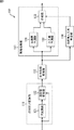
図1は、本発明を適用した画像変換装置101の一実施の形態を示すブロック図である。画像変換装置101は、巡回型IP変換部111、出力位相変換部112、自然画予測部131、人工画予測部132、自然画人工画判定部114、および、合成部133により構成される。また、巡回型IP変換部111は、IP変換部121および巡回型変換部122により構成される。
FIG. 1 is a block diagram showing an embodiment of an
巡回型IP変換部111のIP変換部121および巡回型変換部122には、処理対象となるインターレース方式のSD画像が入力される。
An interlaced SD image to be processed is input to the
IP変換部121は、所定の方法に基づいて、入力されたインターレース方式のSD画像(以下、入力画像とも称する)をプログレッシブ方式のSD画像(以下、中間画像とも称する)にIP変換し、IP変換したプログレッシブ方式のSD画像を巡回型変換部122に供給する。
Based on a predetermined method, the
巡回型変換部122は、入力画像と、1フレーム前に巡回型変換部122から出力されたプログレッシブ方式のSD画像(以下、出力画像とも称する)との間の動きベクトルを求める。巡回型変換部122は、入力画像の画素値と、求めた動きベクトルに基づいて、出力画像に動き補償を施した画像の画素値とを、巡回係数を用いて重み付け加算することにより、中間画像の画質を向上させる。巡回型変換部122は、中間画像をより高画質のプログレッシブ方式のSD画像である出力画像に変換し、出力画像を出力位相変換部112に供給する。なお、巡回係数は、中間画像の各画素について、変換前の入力画像において画素が存在する位置にあるか否か、動きベクトルの垂直方向の大きさ、および、動きベクトルの確からしさを表す信頼度確からしさに基づいて設定される。
The
出力位相変換部112は、巡回型変換部122から供給される第1の画素数のSD画像に対して、水平方向および垂直方向に補間を行うことにより、第1の画素数より多い第2の画素数のHD画像を生成する。出力位相変換部112は、そのHD画像を、自然画予測部131、人工画予測部132、および、自然画人工画判定部114に供給する。
The output
画像処理部113は、自然画人工画判定部114より供給されてくる人工画度に基づいて、HD画像から高品質な画像に処理して、処理結果としての高品質なHD画像を出力する。
The
自然画人工画判定部114は、出力位相変換部112より供給されるHD画像の各画素について、人工画像に分類される領域、または、自然画像に分類される領域のいずれの領域に属するかを判定し、判定結果を人工画度として画像処理部113に出力する。すなわち、人工画度とは、人工画像と自然画像との中間に分類される領域において自然画像における人工画像の割合を0乃至1の値で示したものである。
The natural image / artificial
自然画予測部131は、出力位相変換部112から供給されるHD画像から、そのHD画像のうちの自然画像を高品質にしたHD画像(以下、自然高品質画像と称する)を予測する。具体的には、自然画予測部131は、HD画像の特徴に応じて、そのHD画像から求められる自然高品質画像の画素である注目画素を、自然画像の特徴に適したクラスに分類する。そして、自然画予測部131は、そのクラスに対応する、自然高品質画像を予測するための予測係数と、HD画像とを用いて演算することにより、出力位相変換部112から供給されたHD画像から、自然高品質画像を予測する。自然画予測部131は、その自然高品質画像を合成部133に供給する。
The natural
人工画予測部132は、自然画予測部131と同様に、出力位相変換部112から供給されるHD画像から、そのHD画像のうちの人工画像を高品質にしたHD画像(以下、人工高品質画像と称する)を予測する。具体的には、人工画予測部132は、HD画像の特徴に応じて、そのHD画像から求められる人工高品質画像の画素である注目画素を、人工画像の特徴に適したクラスに分類する。そして、人工画予測部132は、そのクラスに対応する、人工高品質画像を予測するための予測係数と、HD画像とを用いて演算することにより、出力位相変換部112から供給されたHD画像から、人工高品質画像を予測する。人工画予測部132は、その人工高品質画像を合成部133に出力する。
Similar to the natural
合成部133は、自然画人工画判定部114より供給される判定結果に基づいて、自然画予測部131から供給される自然高品質画像の各画素の画素値と、人工画予測部132から供給される人工高品質画像の各画素の画素値とを人工画度に応じた割合で合成し、合成の結果得られるHD画像を出力する。
Based on the determination result supplied from the natural-image / artificial-
次に、図2のフローチャートを参照して、画像変換装置101により実行される画像変換処理を説明する。なお、この処理は、例えば、外部からインターレース方式のSD画像の入力が開始されたとき開始される。
Next, image conversion processing executed by the
ステップS1において、IP変換部121は、IP変換を行う。具体的には、IP変換部121は、所定の方法に基づいて、インターレース方式の入力画像を、プログレッシブ方式の中間画像にIP変換し、IP変換した中間画像を巡回型変換部122に供給する。
In step S1, the
ステップS2において、巡回型変換部122は、巡回型変換処理を行う。具体的には、入力画像と、1フレーム前に巡回型変換部122から出力された出力画像との間の動きベクトルを求める。巡回型変換部122は、入力画像の画素値と、求めた動きベクトルに基づいて、出力画像に動き補償を施した画像の画素値とを、巡回係数を用いて重み付け加算することにより、中間画像の画質を向上させる。巡回型変換部122は、中間画像をより高画質のプログレッシブ方式のSD画像である出力画像に変換し、出力画像を出力位相変換部112に供給する。
In step S2, the
ステップS3において、出力位相変換部112は、出力位相変換処理を行う。具体的には、出力位相変換部112は、巡回型変換部122から供給されるSD画像に対して、水平方向および垂直方向に補間を行うことにより、HD画像を生成する。出力位相変換部112は、そのHD画像を、自然画予測部131、人工画予測部132、および、自然画人工画判定部114に供給する。
In step S3, the
ステップS4において、自然画予測部131は、自然画予測処理を行う。自然画予測処理の詳細は、図6を参照して後述するが、この処理により、HD画像から自然高品質画像が予測され、その自然高品質画像が合成部133に供給される。
In step S4, the natural
ステップS5において、人工画予測部132は、人工画予測処理を行う。人工画予測処理の詳細は、図15を参照して後述するが、この処理により、HD画像から人工高品質画像が予測され、その人工高品質画像が合成部133に出力される。
In step S5, the artificial
ステップS6において、自然画人工画判定部114は、自然画人工画判定処理を行う。自然画予測処理の詳細は、図25を参照して後述するが、自然画人工画判定部114は、出力位相変換部112より供給されるHD画像の各画素について、人工画像に分類される領域、または、自然画像に分類される領域のいずれの領域に属するかを判定し、判定結果を人工画度として合成部133に出力する。
In step S6, the natural-image / artificial-
ステップS7において、合成部133は、画像を合成する。具体的には、合成部133は、自然画人工画判定部114より供給される判定結果に基づいて、自然画予測部131から供給される自然高品質画像の各画素の画素値と、人工画予測部132から供給される人工高品質画像の各画素の画素値とを人工画度に応じた割合で合成する。合成部133は、合成した画像を後段の装置に出力する。
In step S7, the
なお、複数の画像の画像変換を連続して行う場合、上述したステップS1乃至S7の処理が繰り返し実行される。 In addition, when performing image conversion of a plurality of images continuously, the processes in steps S1 to S7 described above are repeatedly executed.
図3は、図1の自然画予測部131の構成例を示すブロック図である。
FIG. 3 is a block diagram illustrating a configuration example of the natural
図3の自然画予測部131は、クラスタップ抽出部551、ADRC(Adaptive Dynamic Range Coding)処理部552、係数種メモリ553、予測係数生成部554、予測係数メモリ555、予測タップ抽出部556、および予測演算部557により構成され、図1の出力位相変換部112から供給されるプログレッシブ方式のHD画像から、そのHD画像のうちの自然画像からノイズなどを除去して、高品質にした自然高品質画像を予測する。
3 includes a class
自然画予測部131には、図1の出力位相変換部112から供給される、プログレッシブ方式のHD画像が入力され、そのHD画像はクラスタップ抽出部551と予測タップ抽出部556に供給される。
The progressive HD image supplied from the output
クラスタップ抽出部551は、入力されたHD画像により求められる、自然高品質画像を構成する画素を、順次、注目画素とし、その注目画素をクラスに分類するために用いる、入力されたHD画像を構成する画素の幾つかを、クラスタップとして抽出する。クラスタップ抽出部551は、抽出されたクラスタップを、ADRC処理部552に供給する。
The class
ADRC処理部552は、クラスタップ抽出部551から供給されるクラスタップを構成する画素の画素値を、クラスタップの波形の特徴として、その画素値に対してADRC処理などを行い、その結果得られるADRCコードを、クラスタップの特徴として検出する。
The
なお、KビットADRCにおいては、例えば、クラスタップを構成する画素の画素値の最大値MAXと最小値MINが検出され、DR=MAX-MINを、集合の局所的なダイナミックレンジとし、このダイナミックレンジDRに基づいて、クラスタップを構成する画素値がKビットに再量子化される。即ち、クラスタップを構成する各画素の画素値から、最小値MINが減算され、その減算値がDR/2Kで除算される。 In the K-bit ADRC, for example, the maximum value MAX and the minimum value MIN of the pixels constituting the class tap are detected, and DR = MAX-MIN is set as the local dynamic range of the set, and this dynamic range Based on DR, the pixel values constituting the class tap are requantized to K bits. That is, the pixel value of each pixel forming the class taps, the minimum value MIN is subtracted, and the subtracted value is divided by DR / 2 K.
そして、以上のようにして得られる、クラスタップを構成するKビットの各画素の画素値を、所定の順番で並べたビット列が、ADRCコードとして出力される。従って、クラスタップが、例えば、1ビットADRC処理された場合には、そのクラスタップを構成する各画素の画素値は、最大値MAXと最小値MINとの平均値で除算されて、除算結果の小数点以下は切り捨てられ、これにより、各画素の画素値が1ビットとされる。即ち、各画素の画素値が2値化される。そして、その1ビットの画素値を所定の順番で並べたビット列が、ADRCコードとして出力される。 A bit string obtained by arranging the pixel values of the K-bit pixels constituting the class tap in a predetermined order is output as an ADRC code. Therefore, for example, when a class tap is subjected to 1-bit ADRC processing, the pixel value of each pixel constituting the class tap is divided by the average value of the maximum value MAX and the minimum value MIN, and the result of the division is The fractional part is rounded down, so that the pixel value of each pixel is 1 bit. That is, the pixel value of each pixel is binarized. Then, a bit string in which the 1-bit pixel values are arranged in a predetermined order is output as an ADRC code.
ADRC処理部552は、検出されたADRCコードに基づいてクラスを決定することにより、注目画素をクラスに分類し、そのクラスを予測係数メモリ555に供給する。例えば、ADRC処理部552は、ADRCコードをそのままクラスとして、予測係数メモリ555に供給する。
The
係数種メモリ553は、図7乃至図9を参照して後述する学習により獲得されたクラスごとの係数種を格納している。予測係数生成部554は、係数種メモリ553から係数種を読み出す。予測係数生成部554は、ユーザにより入力される水平方向の解像度を決定するためのパラメータhと、垂直方向の解像度を決定するためのパラメータvとに基づいて、そのパラメータhとvを含む多項式を用いて、読み出された係数種から予測係数を生成し、予測係数メモリ555に供給して記憶させる。
The
予測係数メモリ555は、ADRC処理部552から供給されるクラスに応じて、そのクラスの予測係数を読み出し、予測演算部557に供給する。
The
なお、予測タップとクラスタップは、同一のタップ構造を有するものとすることも、異なるタップ構造を有するものとすることも可能である。 Note that the prediction tap and the class tap may have the same tap structure or different tap structures.
予測タップ抽出部556は、入力されたHD画像から、注目画素の画素値を予測するのに用いるHD画像を構成する画素を、予測タップとして抽出する。予測タップ抽出部556は、予測タップを予測演算部557に供給する。
The prediction tap extraction unit 556 extracts pixels constituting the HD image used for predicting the pixel value of the target pixel from the input HD image as a prediction tap. The prediction tap extraction unit 556 supplies the prediction tap to the
予測演算部557は、予測タップ抽出部556から供給される予測タップと、予測係数メモリ555から供給される予測係数とを用いて、注目画素の真値の予測値を求める線形一次式の演算などの予測演算を行う。これにより、予測演算部557は、注目画素の画素値の予測値、即ち、自然高品質画像を構成する画素の画素値を求めて合成部133に出力する。
The
図4は、図3のクラスタップ抽出部551により抽出されるクラスタップのタップ構造の一例を示している。
FIG. 4 shows an example of a tap structure of class taps extracted by the class
なお、図中白丸は、出力位相変換部112から供給されるHD画像の画素のうち、クラスタップを構成する画素を表し、点線の丸は、クラスタップを構成しない画素を表し、黒丸は注目画素を表している。このことは、後述する図5においても同様である。
In the figure, white circles represent pixels constituting a class tap among HD image pixels supplied from the output
図4では、9個の画素で、クラスタップが構成されている。即ち、注目画素q6に対応するHD画像を構成する画素p64を中心として、縦方向に1画素置きに並ぶ5画素p60,p61,p64,p67,p68、横方向に1画素置きに並ぶ画素p64を除いた4画素p62,p63,p65,p66から、いわば十字形状のクラスタップが構成されている。 In FIG. 4, a class tap is composed of nine pixels. That is, five pixels p60, p61, p64, p67, p68 arranged every other pixel in the vertical direction and pixels p64 arranged every other pixel in the horizontal direction around the pixel p64 constituting the HD image corresponding to the target pixel q6. The excluded four pixels p62, p63, p65, and p66 constitute a so-called cross-shaped class tap.
図5は、図3の予測タップ抽出部556により抽出される予測タップのタップ構造の一例を示している。 FIG. 5 shows an example of the tap structure of the prediction tap extracted by the prediction tap extraction unit 556 of FIG.
図5では、13個の画素で、予測タップが構成されている。即ち、図5では、出力位相変換部112から供給されるHD画像のうちの、注目画素q8に対応する画素p86を中心として縦方向に1画素置きに並ぶ5画素p80,p82,p86,p90,p92、横方向に1画素置きに並ぶ画素p86を除いた4画素p84、p85,p87,p88、画素p85を中心として、縦方向に1画素置きに並ぶ画素p85を除いた2画素p81,p89、画素p87を中心として、縦方向に1画素置きに並ぶ画素p87を除いた2画素p83,p91から、略ひし形状の予測タップが構成されている。
In FIG. 5, the prediction tap is comprised by 13 pixels. That is, in FIG. 5, among the HD images supplied from the output
なお、図4と図5では、クラスタップを構成する9画素p60乃至p68と、予測タップを構成する13画素p80乃至p92は、上下方向(垂直方向)または左右方向(水平方向)に1画素置きに、即ち2画素間隔で並んでいるが、その間隔は、これに限定されず、出力位相変換部112における変換前のSD画像と変換後のHD画像の画素数の比率、即ち補間倍率に応じて変更するとよい。
4 and 5, the nine pixels p60 to p68 constituting the class tap and the 13 pixels p80 to p92 constituting the prediction tap are arranged every other pixel in the vertical direction (vertical direction) or the horizontal direction (horizontal direction). However, the interval is not limited to this, and the interval depends on the ratio of the number of pixels of the SD image before conversion and the HD image after conversion in the
例えば、水平方向と垂直方向の各画素数が、それぞれ2倍になるように、出力位相変換部112が画像を変換した場合、図4と図5に示されるように、垂直方向または水平方向に2画素間隔で並ぶ画素から、クラスタップと予測タップを構成すると、補間された画素および補間前から存在する画素のうちの一方だけで、クラスタップと予測タップが構成されるので、それらの両方が混在する、例えばクラスタップと予測タップが1画素間隔で並ぶ画素から構成される場合よりも、自然画予測部131による予測処理の結果の精度が向上する。
For example, when the
次に、図6を参照して、図3の自然画予測部131が行う図2のステップS4の自然画予測処理の詳細を説明する。
Next, the details of the natural image prediction process in step S4 of FIG. 2 performed by the natural
初めに、ステップS551において、クラスタップ抽出部551は、図1の出力位相変換部112から入力されたHD画像により求められる自然高品質画像を構成する画素のうちの1つを、注目画素として選択する。
First, in step S551, the class
ステップS552において、クラスタップ抽出部551は、図4に示されるような、ステップS551で選択された注目画素のクラス分類を行うのに用いる、入力されたHD画像を構成する画素の幾つかを、HD画像からクラスタップとして抽出し、ADRC処理部552に供給する。
In step S552, the class
ステップS553において、ADRC処理部552は、クラスタップ抽出部551から供給されるクラスタップを構成する画素の画素値に対して、ADRC処理を行い、その結果得られるADRCコードを、クラスタップの特徴として検出する。
In step S553, the
ステップS554において、ADRC処理部552は、ADRCコードに基づいてクラスを決定することにより、注目画素をクラスに分類し、そのクラスを予測係数メモリ555に供給する。
In step S554, the
ステップS555において、予想係数生成部554は、係数種メモリ553から係数種を読み出す。
In step S555, the predicted
ステップS556において、予測係数生成部554は、ユーザにより入力されたパラメータhとvに基づいて、パラメータhとvを含む多項式を用いて、係数種メモリ553から読み出された係数種から予測係数を生成し、予測係数メモリ555に供給して記憶させる。この係数種から予測係数を生成する処理の詳細については後述する。
In step S556, the prediction
ステップS557において、予測係数メモリ555は、ADRC処理部552から供給されるクラスに基づいて、そのクラスの予測係数を読み出し、予測演算部557に供給する。
In step S557, the
ステップS558において、予測タップ抽出部556は、入力されたHD画像から、図5に示されるような、注目画素の画素値を予測するのに用いるHD画像を構成する画素を、予測タップとして抽出する。予測タップ抽出部556は、予測タップを予測演算部557に供給する。
In step S558, the prediction tap extraction unit 556 extracts, from the input HD image, the pixels constituting the HD image used to predict the pixel value of the target pixel as shown in FIG. 5 as the prediction tap. . The prediction tap extraction unit 556 supplies the prediction tap to the
ステップS559において、予測演算部557は、予測タップ抽出部556から供給される予測タップと、予測係数メモリ555から供給される予測係数とを用いて、注目画素の真値の予測値を求める線形一次式などの予測演算を行う。
In step S559, the
ステップS560において、予測演算部557は、予測演算の結果得られた注目画素の画素値の予測値、即ち、自然高品質画像を構成する画素の画素値を合成部133に出力する。
In step S560, the
ステップS561において、クラスタップ抽出部551は、入力されたHD画像により求められる自然高品質画像を構成するすべての画素を、注目画素としたかどうかを判定する。ステップS561で、すべての画素をまだ注目画素としていないと判定された場合、ステップS562において、クラスタップ抽出部551は、自然高品質画像を構成する画素のうち、まだ注目画素としていないものを、新たに注目画素として決定し、処理をステップS552に戻し、以下同様の処理を繰り返す。一方、ステップS561で、クラスタップ抽出部551は、すべての画素を注目画素としたと判定した場合、自然画予測処理を終了する。
In step S561, the class
以上のようにして、自然画予測部131は、出力位相変換部112から供給されるHD画像から、自然高品質画像を予測し、出力する。即ち、自然画予測部131は、HD画像を自然高品質画像に変換し、出力する。
As described above, the natural
以上のように、図1の画像変換装置101では、出力位相変換部112が、巡回型変換部122から供給されるSD画像を、自然画予測部131から出力するHD画像に変換して、自然画予測部131に供給するので、予測前と予測後の画像の画素数が同一であり、予測前後の画像の画素の位置にはズレがなくなる。
As described above, in the
従って、自然画予測部131は、自然高品質画像の画素である注目画素の位相と同一の位相のHD画像の画素からなる予測タップを用いて、注目画素の画素値を予測することができる。その結果、自然画予測部131は、自然高品質画像を正確に予測し、高精度の画像変換を行うことができる。即ち、出力位相変換部112と自然画予測部131は、巡回型変換部122から入力されるSD画像である画像を、画素数の異なる高品質なHD画像である自然高品質画像に的確に変換することができる。
Therefore, the natural
また、自然画予測部131は、クラスタップを構成する画素の画素値を、クラスタップの波形の特徴として、注目画素をクラスに分類するので、平坦部分が比較的少ない自然画像の特徴を分類するのに適した分類を行うことができる。その結果、自然画予測部131は、HD画像のうちの自然画像の品質を、的確に高めることができる。
Further, since the natural
次に、図3の予測演算部557における予測演算と、その予測演算に用いられる予測係数の学習について説明する。
Next, prediction calculation in the
いま、入力されたHD画像から予測タップを抽出し、その予測タップと予測係数を用いて、自然高品質画像を構成する画素(以下、適宜、自然高品質画像画素と称する)の画素値を予測する所定の予測演算として、例えば、線形1次予測演算を採用することとすると、自然高品質画像画素の画素値yは、次の線形1次式によって求められることになる。 Now, a prediction tap is extracted from the input HD image, and a pixel value of a pixel (hereinafter, appropriately referred to as a natural high quality image pixel) constituting a natural high quality image is predicted using the prediction tap and the prediction coefficient. For example, if a linear primary prediction calculation is employed as the predetermined prediction calculation, the pixel value y of the natural high-quality image pixel is obtained by the following linear primary expression.

但し、式(1)において、xnは、画素値yの自然高品質画像画素についての予測タップを構成する、n番目のHD画像の画素(以下、適宜、HD画像画素と称する)の画素値を表し、Wnは、n番目のHD画像画素の画素値と乗算されるn番目の予測係数を表す。なお、式(1)では、予測タップが、N個のHD画像画素x1,x2,・・・,xNで構成されるものとしてある。 However, in Expression (1), x n is a pixel value of an nth HD image pixel (hereinafter, referred to as an HD image pixel as appropriate) that constitutes a prediction tap for a natural high quality image pixel having a pixel value y. Wn represents the nth prediction coefficient multiplied by the pixel value of the nth HD image pixel. In equation (1), the prediction tap is assumed to be composed of N HD image pixels x 1 , x 2 ,..., X N.
自然高品質画像画素の画素値yは、式(1)に示した線形1次式ではなく、2次以上の高次の式によって求めるようにすることも可能である。 The pixel value y of the natural high-quality image pixel can be obtained not by the linear primary expression shown in Expression (1) but by a higher-order expression of the second or higher order.
いま、第kサンプルの自然高品質画像画素の画素値の真値をykと表すとともに、式(1)によって得られるその真値ykの予測値をyk’と表すと、その予測誤差ekは、次式で表される。 Now, when the true value of the pixel value of the natural high quality image pixel of the k-th sample is expressed as y k and the predicted value of the true value y k obtained by the equation (1) is expressed as y k ′, the prediction error e k is expressed by the following equation.
![]()
![]()
式(2)の予測値yk’は、式(1)にしたがって求められるため、式(2)の予測値yk’を、式(1)にしたがって置き換えると、次式が得られる。 Since the predicted value y k ′ of the formula (2) is obtained according to the formula (1), the following formula is obtained by replacing the predicted value y k ′ of the formula (2) according to the formula (1).
但し、式(3)において、xn,kは、第kサンプルの自然高品質画像画素についての予測タップを構成するn番目のHD画像画素を表す。 In Equation (3), x n, k represents the nth HD image pixel constituting the prediction tap for the natural high quality image pixel of the kth sample.
式(3)または式(2)の予測誤差ekを0、即ち統計的に最小にする予測係数Wnが、自然高品質画像画素を予測するのに最適なものとなるが、すべての自然高品質画像画素について、そのような予測係数Wnを求めることは、一般には困難である。 0 prediction error e k of the formula (3) or formula (2), i.e. the prediction coefficient W n statistically minimizes found is the optimal to predict the high-quality natural image pixel, all natural It is generally difficult to obtain such a prediction coefficient W n for high quality image pixels.
そこで、予測係数Wnが最適なものであることを表す規範として、例えば、最小自乗法を採用することとすると、最適な予測係数Wnは、次式で表される自乗誤差の総和Eを最小にすることで求めることができる。 Therefore, if, for example, the least square method is adopted as a standard indicating that the prediction coefficient W n is optimum, the optimum prediction coefficient W n is obtained by calculating the sum E of square errors expressed by the following equation. It can be obtained by minimizing.
但し、式(4)において、Kは、高品質画像の画素値の真値ykと、その真値ykについての予測タップを構成するHD画像画素x1,k,x2,k,・・・,xN,kとのセットのサンプル数、即ち学習用のサンプルの数を表す。 However, in the formula (4), K is, HD image pixels x 1 constituting the true value y k of the pixel values of the high-quality image, the prediction taps for the true value y k, k, x 2, k, · .., X N, k represents the number of samples, that is, the number of learning samples.
式(4)の自乗誤差の総和Eの最小値は、式(5)に示すように、総和Eを予測係数Wnで偏微分したものを0とするWnによって与えられる。 The minimum value of the sum E of square errors in equation (4) is given by W n , which is 0 as a result of partial differentiation of the sum E by the prediction coefficient W n as shown in equation (5).
そこで、上述の式(3)を予測係数Wnで偏微分すると、次式が得られる。 Therefore, when the above equation (3) is partially differentiated by the prediction coefficient W n , the following equation is obtained.
式(5)と式(6)から、次式が得られる。 From the equations (5) and (6), the following equation is obtained.
式(7)のekに、式(3)を代入することにより、式(7)は、式(8)に示す正規方程式で表すことができる。 By substituting equation (3) into e k in equation (7), equation (7) can be expressed by the normal equation shown in equation (8).
式(8)の正規方程式は、例えば、掃き出し法(Gauss-Jordanの消去法)などを用いることにより、予測係数Wnについて解くことができる。 The normal equation of Expression (8) can be solved for the prediction coefficient W n by using, for example, a sweeping method (Gauss-Jordan elimination method) or the like.
式(8)の正規方程式をクラスごとにたてて解くことにより、最適な予測係数として、自乗誤差の総和Eを最小にする予測係数Wnを、クラスごとに求めることができる。 By solving the normal equation of equation (8) for each class, a prediction coefficient W n that minimizes the sum E of square errors can be obtained for each class as an optimal prediction coefficient.
また、図3の予測係数生成部554において予測係数を生成する多項式と、その多項式に用いられる係数種の学習について説明する。
Also, a polynomial for generating a prediction coefficient in the prediction
いま、入力されたパラメータhとv、並びに係数種を用いて予測係数を生成する式として、例えば、多項式を採用することとすると、クラスごと、かつパラメータhとvの組み合わせごとの予測係数Wnは、次の多項式によって求められる。 As an expression for generating a prediction coefficient using the input parameters h and v and the coefficient type, for example, if a polynomial is adopted, the prediction coefficient W n for each class and each combination of the parameters h and v Is obtained by the following polynomial.
但し、式(9)において、wn,k(k=1,2・・・,9)は、式(14)で表される画素値yの自然高品質画像画素についての予測タップを構成する、n番目のHD画像の画素の画素値xnと乗算されるn番目の予測係数Wnを生成するための係数種のうちの、k番目の項の係数を表す。 However, in Equation (9), w n, k (k = 1, 2,..., 9) constitutes a prediction tap for the natural high quality image pixel having the pixel value y represented by Equation (14). , The coefficient of the k-th term among the coefficient seeds for generating the n-th prediction coefficient W n multiplied by the pixel value x n of the pixel of the n-th HD image.
ここで、パラメータhとvに対応する、n番目の予測係数の真値をWvhnと表すとともに、式(9)によって得られるその真値Wvhnの推測値をWvhn’と表すと、その推測誤差evhnは、次式で表される。 Here, when the true value of the nth prediction coefficient corresponding to the parameters h and v is expressed as W vhn and the estimated value of the true value W vhn obtained by the equation (9) is expressed as W vhn ′, The estimation error e vhn is expressed by the following equation.
![]()
![]()
式(10)の推測値Wvhn’は、式(9)にしたがって求められるため、式(10)の推測値Wvhn’を、式(9)にしたがって置き換えると、次式が得られる。 Since the estimated value W vhn ′ of the equation (10) is obtained according to the equation (9), the following equation is obtained by replacing the estimated value W vhn ′ of the equation (10) according to the equation (9).
なお、式(11)において、wvhn,kは、予測係数Wvhnを生成するための係数種のうちの、k番目の項の係数を表す。また、式(11)において、tkは次式で定義される。 In Equation (11), w vhn, k represents the coefficient of the k-th term among the coefficient types for generating the prediction coefficient W vhn . In the equation (11), t k is defined by the following equation.
式(10)または式(11)の予測誤差evhnを0、即ち統計的に最小にする係数種wvhn,kが、予測係数を推測するのに最適なものとなるが、すべての予測係数について、そのような係数種wvhn,kを求めることは、一般には困難である。 The prediction error e vhn in equation (10) or equation (11) is 0, that is, the coefficient type w vhn, k that statistically minimizes is optimal for estimating the prediction coefficient. In general, it is difficult to obtain such a coefficient seed w vhn, k .
そこで、係数種wvhn,kが最適なものであることを表す規範として、例えば、最小自乗法を採用することとすると、最適な係数種wvhn,kは、次式で表される自乗誤差の総和Eを最小にすることで求めることができる。 Therefore, if the least square method is adopted as a standard indicating that the coefficient type w vhn, k is optimal, for example, the optimal coefficient type w vhn, k is the square error represented by the following equation. Can be obtained by minimizing the sum E of
但し、式(13)において、Vは、パラメータvの種類の数を表し、Hは、パラメータhの種類の数を表す。 However, in Formula (13), V represents the number of types of parameter v, and H represents the number of types of parameter h.
式(13)の自乗誤差の総和Eの最小値は、式(14)に示すように、総和Eを係数種wvhn,kで偏微分したものを0とするwvhn,kによって与えられる。
The minimum value of the sum E of square errors in equation (13) is given by
ここで、XklとYkをそれぞれ以下の式(15)と式(16)で定義すると、式(14)は以下の式(17)の正規方程式に書き換えられる。 Here, if X kl and Y k are defined by the following equations (15) and (16), respectively, equation (14) can be rewritten as a normal equation of the following equation (17).
式(17)の正規方程式は、例えば、掃き出し法(Gauss-Jordanの消去法)などを用いることにより、係数種wn,kについて解くことができる。 The normal equation of the equation (17) can be solved for the coefficient seed wn , k by using, for example, a sweeping method (Gauss-Jordan elimination method) or the like.
式(17)の正規方程式をクラスごとにたてて解くことにより、最適な係数種として、自乗誤差の総和Eを最小にする係数種wn,kを、クラスごとに求めることができる。 By solving the normal equation of Equation (17) for each class, the coefficient type wn , k that minimizes the sum E of square errors can be obtained for each class as the optimum coefficient type.
図7は、式(17)の正規方程式をたてて解くことによりクラスごとの係数種wn,kを求める学習を行う学習装置601の構成例を示すブロック図である。
FIG. 7 is a block diagram illustrating a configuration example of a
図7の学習装置601は、帯域制限フィルタ611、クラスタップ抽出部612、ADRC処理部613、予測タップ抽出部614、正規方程式生成部615、予測係数生成部616、正規方程式生成部617、係数種決定部618、および係数種メモリ619により構成される。
7 includes a
学習装置601には、図示せぬデータベースから読み出された、予測処理後の目標の自然画像となる教師画像が複数入力され、その教師画像は、帯域制限フィルタ611と正規方程式生成部615に供給される。また、学習装置601には、ユーザの指示に基づいて、パラメータhとvが外部から入力され、帯域制限フィルタ611と正規方程式生成部615に供給される。なお、学習装置601には、1枚の教師画像が学習装置601に入力されるごとに、パラメータhとvの全通りの組み合わせが入力されるようになっている。
The
帯域制限フィルタ611は、外部から入力されるパラメータhとvに応じて、図示せぬデータベースから取得された教師画像の、垂直方向および水平方向の帯域をそれぞれ制限するフィルタ処理を行う。これにより、パラメータhとvの組み合わせごとの、予測処理が行われる前の自然画像に相当する生徒画像が生成される。例えば、パラメータhの種類が9種類であり、パラメータvの種類が9種類である場合、帯域制限フィルタ611は、外部から入力されるパラメータhとvに応じて、1枚の教師画像から81種類の生徒画像を生成する。
The
帯域制限フィルタ611は、その生徒画像をクラスタップ抽出部612と予測タップ抽出部614に供給する。
The
クラスタップ抽出部612は、図3のクラスタップ抽出部551と同様に構成される。クラスタップ抽出部612は、教師画像を構成する画素を、順次、注目教師画素として、その注目教師画素について、生徒画像から、図4に示されるような、図3のクラスタップ抽出部551が抽出するクラスタップと同一のタップ構造のクラスタップを抽出し、ADRC処理部613に供給する。
The class
ADRC処理部613は、クラスタップ抽出部551から供給されるクラスタップを構成する画素の画素値に対して、ADRC処理などを行い、その結果得られるADRCコードを、クラスタップの特徴として検出する。ADRC処理部613は、そのADRCコードに基づいてクラスを決定し、そのクラスを正規方程式生成部615に供給する。
The
予測タップ抽出部614は、図3の予測タップ抽出部556と同様に構成される。予測タップ抽出部614は、帯域制限フィルタ611から供給される生徒画像から、図5に示されるような、注目教師画素の画素値を予測するのに用いる生徒画像を構成する画素を、予測タップとして抽出する。予測タップ抽出部556は、予測タップを正規方程式生成部615に供給する。
The prediction
正規方程式生成部615は、入力された教師画像と、予測タップ抽出部614から供給される予測タップのペアを、予測係数Wnの学習に用いられる学習対として、ADRC処理部613から供給されるクラスごと、かつ外部から入力されるパラメータhとvの組み合わせごとに、上述した式(8)の正規方程式をたてると、その正規方程式を予測係数生成部616に供給する。
The normal
予測係数生成部616は、正規方程式生成部615から供給されるクラスごとの正規方程式を解くことにより、予測誤差を統計的に最小にする予測係数Wnを、パラメータhとvの組み合わせごと、かつクラスごとに求めて、正規方程式生成部617に供給する。
The prediction
正規方程式生成部617は、予測係数生成部616からの予測係数Wvhnに基づいて、上述した式(17)の正規方程式をクラスごとに生成し、係数種決定部618に出力する。係数種生成部618は、クラスごとの式(17)の正規方程式を解き、クラスごとの係数種wn,kを求めて係数種メモリ619に格納する。この係数種メモリ619に格納された係数種は、図3の係数種メモリ553に格納される。
Based on the prediction coefficient W vhn from the prediction
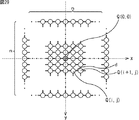
次に、図8を参照して、教師画像と生徒画像の画素の位置関係を説明する。 Next, with reference to FIG. 8, the positional relationship between the pixels of the teacher image and the student image will be described.
図8において、菱形は教師画像の画素を表し、白丸は生徒画像の画素を表している。また、図中横軸は水平方向の位置を表し、縦軸は垂直方向の位置を表す。 In FIG. 8, rhombuses represent pixels of the teacher image, and white circles represent pixels of the student image. In the figure, the horizontal axis represents the horizontal position, and the vertical axis represents the vertical position.
図8に示されるように、教師画像と生徒画像の画素の水平方向および垂直方向の位置は同一となっている。即ち、教師画像と生徒画像は同位相である。 As shown in FIG. 8, the horizontal and vertical positions of the pixels of the teacher image and the student image are the same. That is, the teacher image and the student image are in phase.
次に、図9のフローチャートを参照して、図7の学習装置601の学習処理について説明する。
Next, the learning process of the
初めに、ステップS601において、帯域制限フィルタ611は、入力されたパラメータhとvに応じて、入力された教師画像の垂直方向および水平方向の帯域をそれぞれ制限するフィルタ処理を行うことにより、入力された教師画像から生徒画像を生成し、クラスタップ抽出部612と予測タップ抽出部614に供給する。
First, in step S601, the
ステップS602において、クラスタップ抽出部612は、図3のクラスタップ抽出部551と同様に、教師画像を構成する画素のうちの1つを注目教師画素として、選択する。
In step S602, the class
ステップS603において、クラスタップ抽出部612は、クラスタップ抽出部551と同様に、生徒画像から、図4に示されるようなクラスタップを抽出し、ADRC処理部613に供給する。
In step S <b> 603, the class
ステップS604において、ADRC処理部613は、クラスタップを構成する画素の画素値に対して、ADRC処理を行う。ステップS605において、ADRC処理部613は、ADRC処理の結果得られるADRCコードに基づいて、クラスを決定し、そのクラスを正規方程式生成部615に供給する。
In step S604, the
ステップS606において、予測タップ抽出部614は、図3の予測タップ抽出部556と同様に、注目教師画素について、帯域制限フィルタ611から供給される生徒画像から、図5に示されるような予測タップを抽出し、正規方程式生成部615に供給する。
In step S606, the prediction
ステップS607において、正規方程式生成部615は、入力される教師画像から注目教師画素を抽出し、その注目教師画素と、予測タップ抽出部614から供給される注目教師画素について構成された予測タップを構成する生徒画像とを対象とした式(8)の足し込みを、パラメータhおよびvの組み合わせごと、かつADRC処理部613から供給されるクラスごとに行う。
In step S <b> 607, the normal
ステップS608において、クラスタップ抽出部612は、入力されるすべての教師画像の画素を注目教師画素としたかどうかを判定する。ステップS608で、まだすべての教師画像の画素を注目教師画素としていないと判定された場合、ステップS609において、クラスタップ抽出部612は、教師画像の画素のうち、まだ注目教師画素としていないものを、新たに注目教師画素として決定する。そして、処理はステップS603に戻り、以下、同様の処理が繰り返される。
In step S608, the class
一方、ステップS608で、すべての教師画像の画素を注目教師画素としたと判定された場合、ステップS610において、正規方程式生成部615は、いままでの処理によって得られたパラメータhおよびvの組み合わせごと、かつクラスごとの式(8)における左辺の行列と、右辺のベクトルを、正規方程式として予測係数生成部616に供給する。
On the other hand, when it is determined in step S608 that all the teacher image pixels are the target teacher pixels, in step S610, the normal
ステップS611において、予測係数生成部616は、正規方程式生成部615から供給される、パラメータhおよびvの組み合わせごと、かつクラスごとの式(8)における左辺の行列と右辺のベクトルによって構成されるクラスごとの正規方程式を解き、パラメータhおよびvの組み合わせごと、かつクラスごとの予測係数Wvhnを求めて、正規方程式生成部617に出力する。
In step S <b> 611, the prediction
ステップS612において、正規方程式生成部617は、予測係数Wvhnに基づいて、式(17)の正規方程式をクラスごとに生成し、係数種決定部618に出力する。
In step S612, the normal
ステップS613において、係数種決定部618は、式(17)の正規方程式を解き、クラスごとの係数種wn,kを求める。係数種メモリ619は、ステップS614において、その係数種wn,kを記憶する。この係数種が図3の係数種メモリ553に記憶される。
In step S613, the coefficient
以上のように、自然画予測部131は、自然画像を用いた学習により獲得された係数種よにり生成された予測係数Wnを用いて、自然高品質画像を予測するので、出力位相変換部112から供給されるHD画像のうちの自然画像の品質を的確に高めることができる。
As described above, the natural
また、自然画予測部131は、クラスタップを構成する画素の画素値を、クラスタップの波形の特徴として、その特徴に応じて、注目画素をクラスに分類するので、自然画像の注目画素を、的確に分類することができる。その結果、自然画予測部131は、このクラスごとに学習により獲得された係数種により生成された予測係数を用いて、HD画像から自然高品質画像を予測することにより、自然画像に含まれるノイズ等をより的確に除去し、より高品質の自然高品質画像を出力することができる。
In addition, the natural
図10は、図1の人工画予測部132の第1の実施の形態の詳細構成例を示している。
FIG. 10 shows a detailed configuration example of the first embodiment of the artificial
図10の人工画予測部132は、クラス分類部651、係数種メモリ652、予測係数生成部653、予測係数メモリ654、および予測部655により構成され、出力位相変換部112から供給されるプログレッシブ方式のHD画像から、そのHD画像のうちの人工画像からノイズなどを除去して、高品質にした人工高品質画像を予測する。
10 includes a
出力位相変換部112から供給されるHD画像は、クラス分類部651と予測部655に入力される。クラス分類部651は、そのHD画像により求められる人工高品質画像を構成する画素を、順次、注目画素とし、その注目画素を、HD画像の位相の特徴に応じて、幾つかのクラスのうちのいずれかのクラスに分類する。クラス分類部651は、分類されたクラスを予測係数メモリ654に供給する。
The HD image supplied from the output
係数種メモリ652は、例えばROM(Read Only Memory)などにより構成され、図17乃至図19を参照して後述する学習により獲得されたクラスごとの係数種を格納している。
The
予測係数生成部653は、ユーザにより入力されるパラメータhとvを含む式(9)の多項式を用いて、係数種メモリ652より読み出された係数種wn,kから予測係数Wnを生成し、予測係数メモリ654に記憶させる。
The prediction
予測係数メモリ654は、クラス分類部651から供給されるクラスに基づいて、そのクラスの予測係数Wnをから読み出し、予測部655に供給する。
The
予測部655は、HD画像と、予測係数メモリ654から供給される予測係数Wnとを用いて、注目画素の真値の予測値を求める所定の予測演算を行う。これにより、予測部655は、注目画素の画素値の予測値、即ち、人工高品質画像を構成する画素の画素値を求めて、図1の合成部133に出力する。
The
図11は、図10のクラス分類部651の詳細構成例を示すブロック図である。
FIG. 11 is a block diagram illustrating a detailed configuration example of the
図11のクラス分類部651は、クラスタップ抽出部671、差分算出部672、およびADRC処理部673により構成される。
The
クラスタップ抽出部671は、注目画素をクラスに分類するために用いるHD画像を構成する画素の幾つかを、クラスタップとして抽出し、差分算出部672に供給する。
The class
差分算出部672は、クラスタップ抽出部671から供給されるクラスタップを構成する画素のうちの、隣接する2つの画素どうし(以下、隣接画素と称する)の画素値の差分の絶対値(以下、隣接差分絶対値と称する)を、クラスタップの位相の特徴として、隣接画素ごとに算出する。差分算出部672は、各隣接画素の隣接差分絶対値を、ADRC処理部673に供給する。
The
ADRC処理部673は、差分算出部672から供給される隣接差分絶対値に対して、1ビットADRC処理を行う。具体的には、ADRC処理部673は、クラスタップの隣接差分絶対値を、その最大値MAXと最小値MINとの平均値で除算し、その除算結果の小数点以下を切り捨てることにより、隣接差分絶対値を1ビットにする。即ち、ADRC処理部673は、隣接差分絶対値を2値化する。
The
そして、ADRC処理部673は、その1ビットの画素値を所定の順番で並べたビット列を、注目画素のクラスとして決定する。従って、クラスは、クラスタップ内のエッジの位置を表す位相情報となる。即ち、クラスは、クラスタップの位相を縮退した値となる。ADRC処理部673は、決定されたクラスを、図10の予測係数メモリ654に供給する。
Then, the
以上のように、クラス分類部651は、各隣接画素の隣接差分絶対値を、クラスタップの位相の特徴として、その位相の特徴に応じて、注目画素をクラスに分類する。
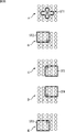
As described above, the
図12は、図11のクラスタップ抽出部671により抽出されるクラスタップのタップ構造の例を示している。なお、クラスタップのタップ構造は、図12に示されている以外の構造とすることも可能である。
FIG. 12 shows an example of a tap structure of class taps extracted by the class
図12では、図1の出力位相変換部112から供給されるHD画像のうちの、注目画素に対応する画素p124と、その画素の上方向、左方向、右方向、下方向にそれぞれ隣接する2画素p120,p121,p122,p123,p125,p126,p127,p128とから、いわば十字形状のクラスタップが構成されている。
In FIG. 12, the pixel p124 corresponding to the target pixel in the HD image supplied from the output
図11の差分算出部672は、クラスタップを構成する9個の画素p120乃至p128のうちの、隣接画素である画素p120とp121,p121とp124,p122とp123,p123とp124,p124とp125,p125とp126,p124とp127,p127とp128の8個の隣接差分絶対値d0乃至d7を算出し、ADRC処理部673に供給する。その結果、ADRC処理部673から8ビットで表されるクラスが出力される。
11 includes the pixels p120 and p121, p121 and p124, p122 and p123, p123 and p124, p124 and p125, which are adjacent pixels, out of the nine pixels p120 to p128 constituting the class tap. Eight adjacent difference absolute values d0 to d7 of p125 and p126, p124 and p127, and p127 and p128 are calculated and supplied to the
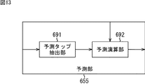
図13は、図10の予測部655の詳細構成例を示すブロック図である。
FIG. 13 is a block diagram illustrating a detailed configuration example of the
図13の予測部655は、予測タップ抽出部691と予測演算部692から構成される。
The
予測タップ抽出部691は、注目画素の画素値を予測するのに用いるHD画像を構成する画素を、予測タップとして抽出する。
The prediction
具体的には、予測タップ抽出部691は、注目画素に対応するHD画像の画素、例えば、注目画素に対して空間的に最も近い位置にあるHD画像の画素に対して、空間的に近い位置にある複数の画素を、HD画像から、予測タップとして抽出する。予測タップ抽出部691は、予測タップを予測演算部692に供給する。
Specifically, the prediction
なお、予測タップとクラスタップは、同一のタップ構造を有するものとすることも、異なるタップ構造を有するものとすることも可能である。 Note that the prediction tap and the class tap may have the same tap structure or different tap structures.
予測演算部692には、予測タップ抽出部691から供給される予測タップのほかに、図10の予測係数メモリ654から予測係数が供給される。予測演算部692は、その予測タップと予測係数とを用いて、注目画素の真値の予測値を求める、式(1)に示した予測演算を行う。これにより、予測演算部692は、注目画素の画素値の予測値、即ち、人工高品質画像を構成する画素の画素値を求めて、図1の合成部133に出力する。
In addition to the prediction tap supplied from the prediction
図14は、図13の予測タップ抽出部691により抽出される予測タップのタップ構造の例を示している。なお、予測タップのタップ構造は、図14に示されている以外の構造とすることも可能である。
FIG. 14 shows an example of the tap structure of the prediction tap extracted by the prediction
図14では、13個の画素で、予測タップが構成されている。即ち、図14では、出力位相変換部112から供給されるHD画像のうちの、注目画素に対応する画素p146を中心として縦方向に並ぶ5画素p140,p142,p146,p150,p152、注目画素に対応する画素p146の左と右に隣接する画素p145,p147それぞれを中心として縦方向に並ぶ3画素p141,p145,p149,p143,p147,p151、および注目画素に対応する画素p146から左と右に2画素だけ離れた画素p144,p148から、略ひし形状の予測タップが構成されている。
In FIG. 14, the prediction tap is comprised by 13 pixels. That is, in FIG. 14, among the HD images supplied from the output
次に、図15を参照して、図10の人工画予測部132が行う図2のステップS5の人工画予測処理の詳細を説明する。
Next, with reference to FIG. 15, the details of the artificial image prediction process in step S5 of FIG. 2 performed by the artificial
初めに、ステップS701において、クラス分類部651は、求める人工高品質画像を構成する画素のうちの所定の画素である注目画素を、その注目画素に対応するHD画像の位相の特徴に応じてクラスに分類するクラス分類処理を行う。このクラス分類処理の詳細は、図16を参照して後述する。
First, in step S701, the
ステップS702において、係数種メモリ652は係数種wn,kを読み出し、予測係数生成部653に出力する。ステップS703において、予測係数生成部653は、ユーザにより入力されたパラメータhとvに基づいて、そのパラメータhとvを含む式(9)の多項式を用いて、係数種wn,kから予測係数Wnを生成し、予測係数メモリ555に供給して記憶させる。
In step S702, the
ステップS704において、予測係数メモリ654は、クラス分類部651により分類されたクラスに基づいて、そのクラスの予測係数Wnを読み出し、予測部655の予測演算部692に供給する。
In step S < b > 704, the
ステップS705において、予測タップ抽出部691は、出力位相変換部112から供給されるHD画像から、図14に示されるような、注目画素の画素値を予測するのに用いるHD画像を構成する画素を、予測タップとして抽出し、予測演算部692に供給する。
In step S705, the prediction
ステップS706において、予測演算部692は、予測タップ抽出部691から供給される予測タップと、予測係数メモリ654から供給される予測係数Wnとを用いて、式(1)に示した予測演算を行うことにより、人工高品質画像を構成する画素の画素値を求める。ステップS707において、予測演算部692は、ステップS706で求められた人工高品質画像を構成する画素の画素値を、図1の合成部133に出力する。
In step S706, the
ステップS708において、クラス分類部651は、人工高品質画像を構成するすべての画素を注目画素としたかどうかを判定し、まだ人工高品質画像を構成するすべての画素を注目画素としていないと判定された場合、ステップS709において、クラス分類部651は、人工高品質画像を構成する画素のうち、まだ注目画素としていないものを新たに注目画素として決定し、処理をステップS701に戻し、以下、同様の処理を繰り返す。
In step S708, the
一方、ステップS708において、クラス分類部651は、人工高品質画像を構成するすべての画素を注目画素としたと判定した場合、人工画予測処理を終了する。
On the other hand, in step S708, when the
以上のようにして、人工画予測部132は、出力位相変換部112から供給されるHD画像から、人工高品質画像を予測し、出力する。即ち、人工画予測部132は、HD画像を人工高品質画像に変換し、出力する。
As described above, the artificial
次に、図16のフローチャートを参照して、図15のステップS701のクラス分類処理について説明する。 Next, the class classification processing in step S701 in FIG. 15 will be described with reference to the flowchart in FIG.
ステップS721において、クラス分類部651のクラスタップ抽出部671(図11)は、図12に示されるような、注目画素のクラス分類を行うのに用いるHD画像を構成する画素の幾つかを、クラスタップとして抽出し、差分算出部672に供給する。
In step S721, the class tap extraction unit 671 (FIG. 11) of the
ステップS722において、差分算出部672は、クラスタップ抽出部671から供給されるクラスタップを構成する画素のうちの、各隣接画素の隣接差分絶対値を算出し、各隣接画素の隣接差分絶対値をADRC処理部673に供給する。
In step S722, the
ステップS723において、ADRC処理部673は、差分算出部672から供給される隣接差分絶対値に対して、1ビットADRC処理を行う。ADRC処理部673は、その結果得られるビット列を、クラスとして決定することにより、注目画素をクラスに分類する。そして、ADRC処理部673は、そのクラスを図10の予測係数メモリ654に供給する。その後、処理は図15のステップS701に戻る。
In step S723, the
図17は、図10の係数種メモリ652に格納される係数種を求める学習を行う学習装置811の構成例を示すブロック図である。
FIG. 17 is a block diagram illustrating a configuration example of the
図17の学習装置811は、生徒画像生成部821、クラス分類部822、生成部823、係数生成部824、正規方程式生成部825、係数種決定部826、および係数種メモリ827により構成される。
17 includes a student
この学習装置811は、上述した自然画予測部131の係数種メモリ553(図3)に格納される係数種wn,kの学習と同様に、係数種を学習する。即ち、学習装置811は、教師画像として、予測処理後の目標の人工画像に相当するHD画像を採用し、生徒画像として、予測処理が行われる前の人工画像に相当するHD画像を採用し、ユーザの指示に基づいて外部から入力されるパラメータhとvの組み合わせごと、かつクラスごとに上述した式(8)の正規方程式をたてて解くことにより、パラメータhとvの組み合わせごと、かつクラスごとの予測係数Wnである予測係数Wvhnを求める。
This
そして、この予測係数Wvhnによりクラスごとに生成される上述した式(17)の正規方程式を解くことで、クラスごとの係数種wn,kが生成され、記憶される。 Then, by solving the normal equation of the above-described equation (17) generated for each class by the prediction coefficient W vhn, the coefficient type wn , k for each class is generated and stored.
学習装置811には、図示せぬデータベースから読み出された教師画像が複数入力され、その教師画像は、生徒画像生成部821と生成部823に供給される。また、学習装置811には、パラメータhおよびvが入力され、生徒画像生成部821、および生成部823に供給される。
A plurality of teacher images read from a database (not shown) are input to the
生徒画像生成部821は、例えばローパスフィルタなどにより構成され、パラメータhおよびvに応じて、図示せぬデータベースから取得された人工画像である教師画像の品質を劣化させることにより、パラメータhおよびvの組み合わせごとの生徒画像を生成する。生徒画像生成部821は、その生徒画像をクラス分類部822と生成部823に供給する。
The student
クラス分類部822は、人工画予測部132の図11のクラス分類部651と同様に構成される。クラス分類部822は、教師画像を構成する画素を、順次、注目教師画素として、その注目教師画素について、生徒画像から、図11のクラスタップ抽出部671が抽出するクラスタップ(図12)と同一のタップ構造のクラスタップを抽出する。
The
そして、クラス分類部822は、クラスタップを構成する画素のうちの各隣接画素の隣接差分絶対値を算出し、その隣接差分絶対値に対して、1ビットADRC処理を行う。クラス分類部822は、その結果得られるビット列を、注目教師画素のクラスとして決定し、生成部823に供給する。
Then, the
生成部823は、教師画像と、生徒画像生成部821から供給される生徒画像のペアを、予測係数の学習に用いられる学習対として、外部から入力されるパラメータhとvの組み合わせごと、かつクラス分類部822から供給されるクラスごとに、式(8)に示した正規方程式をたてると、その正規方程式を、係数生成部824に供給する。
The
係数生成部824は、生成部823から供給される、パラメータhとvの組み合わせごと、かつクラスごとの正規方程式を解くことにより、予測係数Wvhnを、パラメータhとvの組み合わせごと、かつクラスごとに求めて正規方程式生成部825に出力する。
The
正規方程式生成部825は、予測係数Wvhnに基づいて式(17)の正規方程式をクラスごとに生成し、係数種決定部826に出力する。係数種決定部826は、正規方程式を解くことで、係数種wn,kを求め、係数種メモリ827に格納する。係数種メモリ827に格納された係数種wn,kは、図10の係数種メモリ652に格納される。
The normal
図18は、図17の生成部823の詳細構成例を示すブロック図である。
FIG. 18 is a block diagram illustrating a detailed configuration example of the
図18の生成部823は、予測タップ抽出部831と正規方程式生成部832により構成される。
The
生成部823に供給される学習対の生徒画像は、予測タップ抽出部831に供給され、教師画像は、正規方程式生成部832に供給される。
The learning pair student image supplied to the
予測タップ抽出部831は、学習対の教師画像を構成する画素を、順次、注目教師画素とし、その注目教師画素について、学習対の生徒画像から、図13の予測タップ抽出部691が抽出する予測タップ(図14)と同一のタップ構造の予測タップを抽出し、正規方程式生成部832に供給する。
The prediction
正規方程式生成部832は、教師画像から、注目教師画素を抽出し、その注目教師画素と、予測タップ抽出部831から供給される注目教師画素について構成された予測タップを構成する生徒画像とを対象とした足し込みを、外部から入力されるパラメータhとvの組み合わせごと、かつクラス分類部822から供給されるクラスごとに行う。
The normal
そして、正規方程式生成部832は、学習装置811に入力されるすべての教師画像の画素を注目教師画素として、上述の足し込みを行うことにより、各クラスについて、式(8)に示した正規方程式をたてると、その正規方程式を、図17の係数生成部824に供給する。
Then, the normal
次に、図19のフローチャートを参照して、図17の学習装置811の学習処理について説明する。
Next, the learning process of the
初めに、ステップS741において、生徒画像生成部821は、外部から入力されたパラメータhとvに応じて、入力された教師画像から生徒画像を生成し、クラス分類部822と生成部823に供給する。
First, in step S741, the student
ステップS742において、クラス分類部822は、図16のクラス分類処理と同様に、教師画像のうちの所定の画素である注目教師画素を、その注目教師画素に対応する生徒画像の位相の特徴に応じて、クラスに分類するクラス分類処理を行う。クラス分類部822は、決定されたクラスを生成部823の正規方程式生成部832(図18)に供給する。
In step S742, the
ステップS743において、図18の予測タップ抽出部831は、注目教師画素について、生徒画像生成部821から供給される生徒画像から、予測タップを抽出し、正規方程式生成部832に供給する。
In step S743, the prediction
ステップS744において、正規方程式生成部832は、入力される教師画像から注目教師画素を抽出し、その注目教師画素と、予測タップ抽出部831から供給される注目教師画素について構成された予測タップを構成する生徒画像とを対象とした式(8)の足し込みを、パラメータhおよびvの組み合わせごと、かつクラス分類部822から供給されるクラスごとに行う。
In step S744, the normal
ステップS745において、クラス分類部822は、入力されるすべての教師画像の画素を注目教師画素としたかどうかを判定する。ステップS745で、まだすべての教師画像の画素を注目教師画素としていないと判定された場合、ステップS746において、クラス分類部822は、まだ注目教師画素としていない教師画像の画素を、新たに注目教師画素として決定する。そして、処理はステップS742に戻り、以下、同様の処理が繰り返される。
In step S745, the
一方、ステップS745で、すべての教師画像の画素を注目教師画素としたと判定された場合、ステップS747において、正規方程式生成部832は、いままでの処理によって得られたパラメータhおよびvの組み合わせごと、かつクラスごとの式(8)における左辺の行列と、右辺のベクトルを、正規方程式として係数生成部824に供給する。
On the other hand, if it is determined in step S745 that all the teacher image pixels are the target teacher pixels, in step S747, the normal
ステップS748において、係数生成部824は、生成部823から供給される、パラメータhおよびvの組み合わせごと、かつクラスごとの式(8)における左辺の行列と右辺のベクトルによって構成される正規方程式を解き、パラメータhおよびvの組み合わせごと、かつクラスごとの予測係数Wvhnを求め、正規方程式生成部825に出力する。
In step S748, the
ステップS749において、正規方程式生成部825は、予測係数Wvhnに基づいて式(17)の正規方程式をクラスごとに生成し、係数種決定部826に出力する。ステップS750において、係数種決定部826は、クラスごとの式(17)の正規方程式を解き、クラスごとの係数種wn,kを求める。ステップS751において、係数種メモリ827は、係数種wn,kを記憶する。この係数種が図10の係数種メモリ652に記憶される。
In step S749, the normal
以上のように、人工画予測部132は、人工画像を用いた学習により獲得された係数種により生成される予測係数を用いて、人工高品質画像を予測するので、出力位相変換部112から供給されるHD画像のうちの人工画像の品質を的確に高めることができる。
As described above, the artificial
また、人工画予測部132は、クラスタップのエッジの位置を位相の特徴として、その特徴に応じて、注目画素をクラスに分類するので、階調が少なく、位相情報がはっきりした人工画像の注目画素を、的確に分類することができる。その結果、人工画予測部132は、このクラスごとに学習により獲得された係数種により生成される予測係数を用いて、HD画像から人工高品質画像を予測することにより、人工画像に含まれるノイズ等をより的確に除去し、より高品質の人工高品質画像を出力することができる。
Further, since the artificial
次に、図20を参照して、自然画人工画判定部114の詳細構成例について説明する。自然画人工画判定部114は、広域特徴量抽出部911、広域人工画度算出部912、人工画度生成部913、狭域特徴量抽出部914、および狭域人工画度算出部915により構成される。
Next, a detailed configuration example of the natural-image / artificial-
広域特徴量抽出部911は、BEP(Broad Edge Parameter)抽出部931、BFP(Broad Flat Parameter)抽出部932、および特徴量合成部933より構成され、出力位相変換部112より供給されるHD画像の各画素より広域特徴量を抽出して広域人工画度算出部912に供給する。
The wide area feature
BEP抽出部931は、出力位相変換部112より供給されるHD画像の各画素について、注目画素に対応して設定される参照領域の画素の画素値のダイナミックレンジに基づいて得られる値を広域特徴量を構成する特徴量BEPとして抽出し、BFP抽出部932および特徴量合成部933に供給する。尚、BEP抽出部931の詳細な構成例については、図21を参照して後述する。また、以降、参照領域の画素、および特徴量BEPについては、単に参照画素、およびBEPとも称する。さらに、以降の説明において、注目画素とは、出力位相変換部112より供給されるHD画像の画素であって、自然画人工画判定部114における処理対象となる画素である。
The
BFP抽出部932は、出力位相変換部112より供給されるHD画像の各画素について、注目画素に対応して設定される参照画素の隣接する画素間の画素値の差分絶対値およびBEPに基づいて得られる値を、広域特徴量を構成する特徴量BFPとして抽出し、特徴量合成部933に供給する。尚、BFP抽出部932の詳細な構成例については、図22を参照して後述する。また、以降、特徴量BFPについては、単にBFPとも称する。
The
特徴量合成部933は、BEP抽出部931より供給されてくるBEPおよびBFP抽出部932より供給されてくるBFPを合成し、広域特徴量を生成して広域人工画度算出部912に供給する。すなわち、広域特徴量は、上述したBEPおよびBFPという2種類の特徴量より構成され、注目画素の属する広い範囲の画像の特徴を示す特徴量である。
The feature
広域人工画度算出部912は、特徴量分離部951、広域境界線比較部952、広域境界線メモリ953、および内分点計算部954から構成され、広域特徴量抽出部911より供給されてくる広域特徴量に基づいて、広域人工画度Artbを算出し、人工画度生成部913に供給する。
The wide-area artificial image
特徴量分離部951は、広域特徴量抽出部911より供給されてくる広域特徴量を構成する特徴量を分離して、それぞれ広域境界線比較部952に供給する。すなわち、この例においては、広域特徴量は、BEPおよびBFPであるので、特徴量分離部951は、BEPおよびBFPをそれぞれ分離して広域境界線比較部952に供給する。
The feature
広域境界線比較部952は、特徴量分離部951より供給されてくる2種類の特徴量の値に基づいて、予め複数の人工画像および自然画像より統計的に求められており、広域境界線メモリ953に記憶されている人工画像または自然画像のいずれに属するかを示す広域境界線と比較し、比較結果を内分計算部954に供給する。
The wide area boundary
内分計算部954は、広域境界線比較部952より供給されてくる比較結果に基づいて、広域特徴量に対応する広域人工画度Artbを計算して人工画度生成部913に供給する。
Based on the comparison result supplied from the wide area boundary
狭域特徴量抽出部914は、PNDP(Primary Narrow Discrimination Parameter)抽出部971、SNDP(Secondary Narrow Discrimination Parameter)抽出部972、および特徴量合成部973より構成され、出力位相変換部112より供給されるHD画像の各画素より狭域特徴量を抽出して狭域人工画度算出部915に供給する。
The narrow area feature
PNDP抽出部971は、出力位相変換部112より供給されるHD画像の各画素について、注目画素に対応して設定される参照領域に含まれる長タップ領域の画素の画素値のダイナミックレンジに基づいて得られる値を狭域特徴量を構成する特徴量PNDPとして抽出し、SNDP抽出部972および特徴量合成部973に供給する。尚、PNDP抽出部971の詳細な構成例については、図23を参照して後述する。また、以降、単に、特徴量PNDPは、単に、PNDPとも称する。
For each pixel of the HD image supplied from the output
SNDP抽出部972は、出力位相変換部112より供給されるHD画像の各画素について、注目画素に対応して設定される参照領域に含まれる長タップ領域に内包される短タップ領域の画素の画素値のダイナミックレンジおよびPNDPに基づいて得られる特徴量SNDPを狭域特徴量を構成する特徴量として抽出し、特徴量合成部973に供給する。尚、SNDP抽出部972の詳細な構成例については、図24を参照して後述する。また、以降、特徴量SNDPについては、単に、SNDPとも称する。
The
特徴量合成部973は、PNDP抽出部971より供給されてくるPNDPおよびSNDP抽出部972より供給されてくるSNDPを合成し、狭域特徴量を生成して狭域人工画度算出部915に供給する。すなわち、狭域特徴量とは、上述したPNDPおよびSNDPという2種類の特徴量より構成される特徴量であり、注目画素の属する狭い範囲の画像の特徴を示す特徴量である。
The feature
狭域人工画度算出部915は、特徴量分離部991、狭域境界線比較部992、狭域境界線メモリ993、および内分点計算部994から構成され、狭域特徴量抽出部914より供給されてくる狭域特徴量に基づいて、狭域人工画度Artnを算出し、人工画度生成部913に供給する。
The narrow area artificial degree-of-
特徴量分離部991は、狭域特徴量抽出部914より供給されてくる狭域特徴量を構成する特徴量を分離して、それぞれ狭域境界線比較部992に供給する。すなわち、この例においては、狭域特徴量は、PNDPおよびSNDPであるので、特徴量分離部991は、PNDPおよびSNDPをそれぞれ分離して狭域境界線比較部992に供給する。
The feature
狭域境界線比較部992は、特徴量分離部991より供給されてくる2種類の特徴量の値に基づいて、予め複数の人工画像および自然画像より統計的に求められており、狭域境界線メモリ993に記憶されている人工画像または自然画像のいずれに属するかを示す狭域境界線と比較し、比較結果を内分計算部994に供給する。
The narrow area boundary
内分計算部994は、狭域境界線比較部992より供給されてくる比較結果に基づいて、狭域特徴量に対応する狭域人工画度Artnを計算して人工画度生成部913に供給する。
Based on the comparison result supplied from the narrow boundary
人工画度生成部913は、広域人工画度算出部912より供給されてくる広域人工画度Artbと、狭域人工画度算出部915より供給されてくる狭域人工画度Artnとを合成して、人工画度Artを生成して、画像処理部113に出力する。
The articulation
次に、図21を参照して、BEP抽出部931の詳細な構成例について説明する。
Next, a detailed configuration example of the
図21のBEP抽出部931は、バッファ1011、参照画素抽出部1012、重み計算部1013、画素間差分計算部1014、乗算部1015、蓄積部1016、最大値最小値抽出部1017、およびBEP計算部1018から構成される。
21 includes a
バッファ1011は、出力位相変換部112より供給されるHD画像を一時的に記憶し、順次必要に応じて参照画素抽出部1012に供給する。参照画素抽出部1012は、順次、注目画素毎に参照画素を読み出して重み計算部1013および画素間差分計算部1014に供給する。ここで、参照画素とは、注目画素に対応付けて設定される所定の領域内の画素のことであり、例えば、注目画素を中心としたn画素×n画素の範囲の全ての画素である。尚、参照画素については、注目画素に対応付けて設定される複数の画素であればよいので、その他の数、または、配置の画素であっても良いことは言うまでもない。
The
重み計算部1013は、参照画素抽出部1012より供給されてくる参照画素毎に注目画素との距離に応じた重みを計算し乗算部1015に供給する。差分計算部1013は、参照画素抽出部1012より供給されてくる参照画素毎に注目画素との差分値を求めて乗算部1015に供給する。乗算部1015は、重み計算部1013より供給されてくる重みと、画素間差分計算部1014より供給されてくる注目画素と参照画素との差分値とを乗算し、蓄積部1016に蓄積させる。
The
最大値最小値抽出部1017は、蓄積部1016に蓄積されている全ての参照画素と注目画素との差分値に、対応する参照画素と注目画素との距離に応じた重みが乗じられた値が全て蓄積されると、その中から最大値と最小値とを抽出し、BEP計算部1018に供給する。BEP計算部1018は、最大値最小値抽出部1017より供給されてくる、参照画素と注目画素との差分値、すなわち、参照画素と注目画素との差分により求められる差分ダイナミックレンジに、対応する参照画素と注目画素との距離に応じた重みが乗じられた値の差分値を注目画素のBEPとして出力する。尚、差分ダイナミックレンジに重みが乗じられた値を、注目画素からの距離に応じたダイナミックレンジ、または、単に
差分ダイナミックレンジとも称する。
The maximum value / minimum
次に、図22を参照して、BFP抽出部932の詳細な構成例について説明する。
Next, a detailed configuration example of the
図22のBFP抽出部932は、バッファ1031、参照画素抽出部1032、隣接画素間差分計算部1033、関数変換部1034、重み計算部1035、乗算部1036、蓄積部1037、およびBFP計算部1038から構成されている。
22 includes a
バッファ1031は、出力位相変換部112より供給されるHD画像を一時的に記憶し、順次必要に応じて参照画素抽出部1032に供給する。参照画素抽出部1032は、順次、注目画素毎に参照画素を読み出して隣接画素間差分計算部1033および重み計算部1035に供給する。
The
隣接画素間差分計算部1033は、参照画素抽出部1032より供給されてきた全ての参照画素について隣接画素間の差分絶対値を関数変換部1034に供給する。関数変換部1034は、BEP抽出部931より供給されてくるBEPに基づいて、変換関数を設定すると供に、隣接画素間差分計算部1033より供給されてくる隣接画素間差分絶対値を、設定した変換関数で変換し乗算部1036に供給する。
The inter-adjacent pixel
重み計算部1035は、参照画素抽出部1032より供給されてくる参照画素の画素間の位置毎に、注目画素からの距離に応じた重みを計算し乗算部1036に供給する。乗算部1036は、重み計算部1035より供給されてくる重みと、関数変換部1034より供給されてくる関数変換された参照画素間差分絶対値とを乗算し、蓄積部1037に蓄積させる。
The
BFP計算部1038は、蓄積部1037に蓄積されている乗算結果を累積加算し、注目画素のBFPとして出力する。
The
次に、図23を参照して、PNDP抽出部971の詳細な構成例について説明する。
Next, a detailed configuration example of the
図23のPNDP抽出部971は、バッファ1051、参照画素抽出部1052、長タップ抽出部1053、画素値抽出部1054、最大値最小値抽出部1055、およびPNDP計算部1056から構成されている。
23 includes a
バッファ1051は、出力位相変換部112より供給されるHD画像を一時的に記憶し、順次必要に応じて参照画素抽出部1052に供給する。参照画素抽出部1052は、順次、注目画素毎に参照画素を読み出して、長タップ抽出部1053に供給する。
The
長タップ抽出部1053は、参照画素のうち、参照画素の領域に含まれる、すなわち、参照画素の領域と同様であるか、または、それよりも小さな領域から画素を抽出して画素値蓄積部1054に供給する。また、長タップ抽出部1053は、長タップの情報をSNDP抽出部972の短タップ抽出部1073にも供給する。さらに、長タップ抽出部1053は、長タップについて、全ての抽出が終了した段階で、その旨を最大値最小値抽出部1055に供給する。
The long
最大値最小値抽出部1055は、画素値蓄積部1054に蓄積された長タップの全ての画素値のうち、最大値と最小値を抽出してPNDP計算部1056に供給する。
The maximum value / minimum
PNDP計算部1056は、最大値最小値抽出部1055より供給されてくる画素値の最大値と最小値との差分値より参照画素の画素値ダイナミックレンジを求め、注目画素のPNDPとして出力する。ここで、画素値ダイナミックレンジとは、所定の領域に含まれる全ての画素値の最大値から最小値を引いた値である。
The
次に、図24を参照して、SNDP抽出部972の詳細な構成例について説明する。
Next, a detailed configuration example of the
図24のSNDP抽出部972は、バッファ1071、参照画素抽出部1072、短タップ抽出部1073、画素値蓄積部1074、最大値最小値抽出部1075、DR計算部1076、DR蓄積部1077、およびSNDP選択部1078から構成されている。
24 includes a
バッファ1071は、出力位相変換部112より供給されるHD画像を一時的に記憶し、順次必要に応じて参照画素抽出部1072に供給する。参照画素抽出部1072は、順次、注目画素毎に参照画素を読み出して、短タップ抽出部1073に供給する。
The
短タップ抽出部1073は、長タップ抽出部1053より供給されてくる長タップの情報に基づいて、注目画素を含む領域であって、長タップに含まれる領域と同様であるか、または、それよりも小さな、複数の領域から画素を抽出して画素値蓄積部1074に供給する。すなわち、長タップが1個について、短タップは、複数のパターンが設定されることがある。また、短タップ抽出部1073は、複数の短タップについて、全てのパターンについて抽出が終了した段階で、その旨をSNDP選択部1078に供給する。
The short
最大値最小値抽出部1075は、画素値蓄積部1074に蓄積された、短タップに含まれる全ての画素値のうち、最大値と最小値を抽出してDR計算部1076に供給する。
The maximum value / minimum
DR計算部1076は、最大値最小値選択部1075より供給されてくる短タップに含まれる全ての画素値のうち、最大値と最小値との差分から画素値ダイナミックレンジを求め、DR蓄積部1077に蓄積させる。
The
SNDP1079は、短タップ抽出部1073より全てのパターンの短タップについて抽出が終了したことが通知されると、DR蓄積部1077に蓄積されている、全てのパターンの短タップ毎に求められている画素値ダイナミックレンジより、最小値を選択し、SNDPとして出力する。
When the SNDP 1079 is notified by the short
次に、図25のフローチャートを参照して、自然画人工画判定処理について説明する。 Next, the natural image / artificial image determination process will be described with reference to the flowchart of FIG.
ステップS831において、広域特徴量抽出部911のBEP抽出部931は、BEP抽出処理を実行し、出力位相変換部112より供給されるHD画像より画素毎にBEPを抽出して特徴量合成部933に供給する。
In step S831, the
ここで、図26のフローチャートを参照して、図21のBEP抽出部931によるBEP抽出処理について説明する。
Here, the BEP extraction processing by the
ステップS851において、バッファ1011は、出力位相変換部112より供給されるHD画像を一時的に記憶する。
In step S851, the
ステップS852において、参照画素抽出部1012は、バッファ1011より、未処理の画素を注目画素に設定すると供に、ステップS853において、注目画素に対応して設定されている参照画素を読み出して重み計算部1013および画素間差分計算部1014に供給する。ここで、参照画素とは、例えば、注目画素に対応付けて設定される所定の領域内の画素のことであり、例えば、図27で示されるように、注目画素を中心としてn画素×n画素の範囲の全ての画素である。
In step S852, the reference
尚、図27においては、画像内における参照領域R内の黒丸印の注目画素Q(0,0)を中心としたx方向およびy方向の2次元空間の座標上の白丸印が参照画素Q(i,j)を示しており、注目画素Q(0,0)を中心としてn個×n個の点線で囲まれた範囲内の画素が、参照画素Q(i,j)(−(n−1)/2≦i≦(n−1)/2,−(n−1)/2≦j≦(n−1)/2:i,jは、整数)であることが示されている。 In FIG. 27, the white circles on the coordinates in the two-dimensional space in the x and y directions centered on the noticed pixel Q (0, 0) of the black circle in the reference region R in the image are the reference pixels Q ( i, j), and a pixel within a range surrounded by n × n dotted lines centered on the pixel of interest Q (0,0) is a reference pixel Q (i, j) (− (n− 1) / 2 ≦ i ≦ (n−1) / 2, − (n−1) / 2 ≦ j ≦ (n−1) / 2: i and j are integers).
ステップS854において、画素間差分計算部1014は、注目画素と未処理の参照画素との画素間の画素値の差分値を計算し、乗算部1015に供給する。すなわち、図27においては、画素間差分計算部1014は、画素間差分値として、(Q(0,0)−Q(i,j))を計算して乗算部1015に供給する。尚、画素間差分値におけるQ(0,0),Q(i,j)は、注目画素Q(0,0)および参照画素Q(i,j)のそれぞれの画素値である。
In step S854, the inter-pixel
ステップS855において、重み計算部1013は、注目画素と未処理の参照画素との距離に応じた重みを計算し、計算結果である重みを乗算部1015に供給する。より具体的には、例えば、画素間差分値を求めた参照画素が、参照画素Q(i,j)の場合、重み計算部1013は、座標のパラメータを用いて、例えば、重みとしてwd=a/(i2+j2)(a:定数)を計算する。尚、重みwdは、距離に応じて近いほど大きく、遠いほど小さくなるように値が求められれば良いので、上述の方法以外で計算するようにしてもよく、例えば、重みwd=a/√(i2+j2)(a:定数)などでもよい。
In step S855, the
ステップS856において、乗算部1015は、画素間差分計算部1014より供給されてきた画素間差分値と、重み計算部1013より供給されてきた重みとを乗算し、蓄積部1016に蓄積させる。すなわち、図27の場合、乗算部1015は、画素間差分計算部1014より供給されてきた画素間差分値(Q(0,0)−Q(i,j))と、重み計算部1013より供給されてきた重みwdとを乗算し、乗算結果としてwd×(Q(0,0)−Q(i,j))を蓄積部1016に蓄積させる。
In step S856, the
ステップS857において、画素間差分計算部1014は、未処理の参照画素が存在するか否かを判定し、未処理の参照画素が存在する場合、その処理は、ステップS854に戻る。すなわち、全ての参照画素について、ステップS854乃至S857の処理が繰り返される。
In step S857, the inter-pixel
そして、ステップS857において、未処理の参照画素がない、すなわち、全ての参照画素について注目画素との差分値が求められ、さらに、距離に応じた重みwdが設定され、それらが乗算されて蓄積部1016に全て蓄積されていると判定された場合、ステップS858において、画素間差分計算部1014は、全ての参照画素について処理が終了したことを最大値最小値抽出部1017に通知する。最大値最小値抽出部1017は、蓄積部1016に蓄積されている乗算結果のうち、最大値となる値と最小値となる値とを抽出してBEP計算部1018に供給する。
In step S857, there is no unprocessed reference pixel, that is, the difference value from the target pixel is obtained for all the reference pixels, and a weight w d corresponding to the distance is set and multiplied and accumulated. If it is determined that all are stored in the
ステップS859において、BFP計算部1018は、最大値最小値抽出部1017より供給されてきた乗算結果の最大値より最小値を引いた値である参照画素の差分ダイナミックレンジを、注目画素に対するBEPとして計算し、BFP抽出部932および特徴量合成部933に供給する。
In step S859, the
ステップS860において、参照画素抽出部1012は、バッファ1011に記憶されている画像における全ての画素について、BEPが求められたか否かを判定する。ステップS860において、画像の全ての画素についてBEPが求められていない場合、処理は、ステップS852に戻る。すなわち、バッファ1011に記憶された画像の全ての画素についてBEPが求められるまで、ステップS852乃至S860の処理が繰り返される。そして、ステップS860において、画像内の全ての画素についてBEPが求められたと判定された場合、BEP抽出処理が終了する。
In step S860, the reference
以上の処理により、BEPとして画像における広域のエッジを表現する特徴量であるBEPが求められる。すなわち、BEPは、注目画素に対する参照画素内の差分ダイナミックレンジを表現することで、注目画素が属する広域領域にエッジが存在したような場合、大きな値となり、逆にエッジが存在しない場合、小さな値を取ることになる。 Through the above processing, a BEP that is a feature amount representing a wide edge in an image is obtained as a BEP. In other words, the BEP expresses the differential dynamic range in the reference pixel with respect to the target pixel, and becomes a large value when an edge exists in the wide area to which the target pixel belongs, and conversely, a small value when there is no edge. Will take.
ここで、図25のフローチャートの説明に戻る。 Now, the description returns to the flowchart of FIG.
ステップS831におけるBEP抽出処理によりBEPが画像より抽出されると、ステップS832において、広域特徴量抽出部911のBFP抽出部932は、BFP抽出処理を実行し、出力位相変換部112より供給されるHD画像より画素毎にBFPを抽出して特徴量合成部933に供給する。
When the BEP is extracted from the image by the BEP extraction process in step S831, the
ここで、図28のフローチャートを参照して、図22のBFP抽出部932によるBFP抽出処理について説明する。
Here, the BFP extraction processing by the
ステップS871において、バッファ1031は、出力位相変換部112より供給されるHD画像を一時的に記憶する。
In step S871, the
ステップS872において、参照画素抽出部1032は、バッファ1011より、未処理の画素を注目画素に設定すると供に、ステップS873において、注目画素に対応して設定されている参照画素を読み出して隣接画素間差分計算部1033および重み計算部1035に供給する。
In step S872, the reference
ステップS874において、画素間差分計算部1033は、未処理の参照画素間(注目画素を含む)の画素値の差分絶対値を計算し、関数変換部1034に供給する。すなわち、図29においては、画素間差分計算部1033は、隣接画素間差分絶対値eとして、例えば、e=|Q(i+1,j)−Q(i,j)|を計算して関数変換部1034に供給する。尚、画素間差分絶対値におけるQ(i+1,j),Q(i,j)は、参照画素Q(i+1,j),Q(i,j)のそれぞれの画素値である。また、図29における黒丸印は、注目画素Q(0,0)である。
In step S874, the inter-pixel
さらに、参照画素の隣接間差分絶対値eは、図29における丸印で示される各画素のx方向およびy方向に隣接する画素との画素値の差分絶対値である。したがって、参照画素Q(i,j)の隣接画素間差分絶対値eは、|Q(i+1,j)−Q(i,j)|,|Q(i,j+1)−Q(i,j)|,|Q(i−1,j)−Q(i,j)|,|Q(i,j−1)−Q(i,j)|の4種類の隣接画素間差分絶対値が設定される。ただし、参照画素の設定されている領域の辺縁部の画素については、xy方向の正方向または負方向いずれか1方向に参照画素と隣接していないので、3種類の隣接画素間差分絶対値が設定される。また、参照画素のうち、参照画素が設定されている領域の4箇所の角となる位置の参照画像については、xy方向の正方向または負方向いずれか2方向に参照画素と隣接していないので、2種類の隣接画素間差分絶対値が設定される。結果として、注目画素を中心としてn画素×n画素の参照画素が設定される場合、2n(n−1)個の画素間差分絶対値が設定されることになる。 Further, the difference absolute value e between adjacent reference pixels is a difference absolute value of a pixel value of each pixel indicated by a circle in FIG. 29 with a pixel adjacent in the x direction and the y direction. Accordingly, the difference value e between adjacent pixels of the reference pixel Q (i, j) is | Q (i + 1, j) −Q (i, j) |, | Q (i, j + 1) −Q (i, j). |, | Q (i-1, j) -Q (i, j) |, | Q (i, j-1) -Q (i, j) | The However, since the pixels at the edge of the region where the reference pixel is set are not adjacent to the reference pixel in either the positive or negative direction of the xy direction, the difference absolute value between the three types of adjacent pixels Is set. Further, among the reference pixels, the reference image at the four corners of the region where the reference pixel is set is not adjacent to the reference pixel in either the positive or negative direction of the xy direction. Two types of absolute difference values between adjacent pixels are set. As a result, when n pixels × n reference pixels are set around the pixel of interest, 2n (n−1) inter-pixel difference absolute values are set.
ステップS875において、関数変換部1034は、BEP抽出部931より供給されてくるBEPにより設定される関数fに基づいて、隣接画素間差分計算部1033より供給されてきた隣接画素間差分絶対値eを変換して、乗算部1036に供給する。より詳細には、関数変換部1034は、BEP抽出部931より供給されてくるBEPにより設定される以下の式(18)に基づいて、値を変換し、変換した値を乗算部1036に出力する。
In step S875, the function conversion unit 1034 uses the adjacent pixel difference absolute value e supplied from the adjacent pixel
式(18)においては、隣接画素間差分絶対値eが閾値th=BEP/bより大きい場合、0が乗算部1036に出力され、隣接画素間差分絶対値eが閾値th=BEP/b以下である場合、1が乗算部1036に出力されることが示されている。尚、ここで、bは、定数である。また、閾値thの計算に用いられるBEPは、注目画素のBEPである。さらに、閾値thは、BEPの傾向が利用できればよいので、閾値th=BEP/b以外のBEPを用いた閾値でもよく、例えば、閾値th=(√BEP)/b、または、閾値th=(BEP)2/bなどを利用するようにしても良い。
In Expression (18), when the difference absolute value e between adjacent pixels is larger than the threshold th = BEP / b, 0 is output to the
ステップS876において、重み計算部1035は、注目画素と、隣接画素間差分絶対値を計算した画素間の中央位置との距離に応じた重みを計算し、計算結果である重みweを乗算部1036に供給する。より具体的には、例えば、隣接画素間差分絶対値を求めた参照画素が、参照画素Q(i,j),Q(i+1,j),の場合、重み計算部1013は、座標のパラメータを用いて、例えば、重みとしてwe=a/((i+1/2)2+j2)(a:定数)を計算する。尚、重みweは、距離に依存した値が求められれば良いので、上述の方法以外で計算するようにしてもよく、例えば、重みwe=a/√((i+1/2)2+j2)(a:定数)などでもよい。
In step S876, the
ステップS877において、乗算部1036は、関数変換部1034より供給されてきた隣接画素間差分絶対値eと、重み計算部1035より供給されてきた重みweとを乗算し、ステップS878において、蓄積部1037に蓄積させる。すなわち、図29の場合、乗算部1036は、関数変換部1034より供給されてきた変換結果である1または0と、重み計算部1035より供給されてきた重みweとを乗算し、乗算結果としてweまたは0を蓄積部1036に蓄積させる。
In step S877, the
ステップS879において、隣接画素間差分計算部1033は、未処理の参照画素が存在するか否か、すなわち、隣接画素間差分絶対値が設定されているにもかかわらず、求められていないものがあるか否かを判定し、存在する場合、その処理は、ステップS874に戻る。このとき、全ての隣接画素間差分絶対値について、ステップS874乃至S879の処理が繰り返される。すなわち、上述したように、図29で示されるように、参照画素がn画素×n画素で設定されている場合、2n(n−1)個の隣接画素間差分絶対値が求められることになるので、ステップS874乃至S879の処理が、2n(n−1)回繰り返されることになる。
In step S879, the inter-adjacent pixel
そして、ステップS879において、未処理の参照画素がない、すなわち、全ての隣接画素間差分絶対値が求められて関数変換され、さらに、距離に応じた重みが設定され、それらが乗算されて蓄積部1037に全て蓄積されていると判定された場合、ステップS880において、隣接画素間差分計算部1033は、全ての参照画素について処理が終了したことをBFP計算部1038に通知する。BFP計算部1038は、蓄積部1037に蓄積されている乗算結果の総和を求めてBFPとして出力する。
In step S879, there is no unprocessed reference pixel, that is, all adjacent pixel difference absolute values are obtained and function-converted, weights corresponding to the distances are set, they are multiplied, and the storage unit If it is determined that all are stored in 1037, in step S880, the adjacent pixel
ステップS881において、参照画素抽出部1032は、バッファ1011に記憶されている画像における全ての画素について、BFPが求められたか否かを判定する。ステップS881において、画像の全ての画素についてBFPが求められていない場合、処理は、ステップS872に戻る。すなわち、バッファ1031に記憶された画像の全ての画素についてBFPが求められるまで、ステップS872乃至S881の処理が繰り返される。そして、ステップS881において、画像内の全ての画素についてBFPが求められたと判定された場合、BFP抽出処理が終了する。
In step S881, the reference
以上の処理により、画像における広域の平坦部を表現する特徴量としてBFPが求められる。すなわち、BFPは、仮に重みweが距離に応じたものではなく、均一に1であった場合、参照画素のうち、閾値thよりも小さい隣接画素間差分絶対値の数がカウントされた値となる。結果として、BFPは、注目画素の属する広域的な範囲が平坦である場合、値が大きくなり、逆に、エッジなどが多く存在する、平坦ではないような場合、値が小さくなる。 Through the above processing, BFP is obtained as a feature amount representing a wide flat portion in the image. That, BFP is, if not the weight w e is corresponding to the distance, if uniformly was 1, among the reference pixels, and values which the number counted in the small adjacent-pixel difference absolute value than the threshold value th Become. As a result, the BFP value increases when the wide range to which the pixel of interest belongs is flat, and conversely, the value decreases when there are many edges or the like and the value is not flat.
尚、以上においては、隣接画素間差分絶対値を求めるに当たり、参照画素の全ての隣接画素間の差分絶対値を求める例について説明してきたが、隣接している画素間の画素値の関係が明らかになる値が抽出できれば良いので、その他の方法で隣接画素間差分絶対値を求めるようにしてもよく、例えば、図29におけるx方向、または、y方向の何れかの方向に隣接する画素間の画素値の差分絶対値を求めるようにしても良いし、各参照画素について、上下方に隣接するそれぞれの画素との隣接画素間差分絶対値の和、左右に隣接するそれぞれの画素との隣接画素間差分絶対値の和、または上下左右方向に隣接するそれぞれの画素との画素間差分絶対値の総和などを隣接画素間差分絶対値として利用するようにしてもよい。さらに、以降の説明においても隣接画素間差分絶対値を求める処理があるが、上述のように様々な形式を用いるようにしてよいことは同様である。 In the above description, the example of obtaining the absolute difference value between all adjacent pixels of the reference pixel has been described in calculating the absolute difference value between adjacent pixels. However, the relationship between the pixel values between adjacent pixels is clear. The absolute value of the difference between adjacent pixels may be obtained by other methods, for example, between pixels adjacent in either the x direction or the y direction in FIG. You may make it obtain | require the absolute difference value of a pixel value, and about each reference pixel, the sum of the absolute difference value between adjacent pixels with each pixel adjoining up and down, the adjacent pixel with each pixel adjacent to right and left The sum of absolute differences between pixels or the sum of absolute differences between pixels with pixels adjacent in the vertical and horizontal directions may be used as the absolute difference between adjacent pixels. Further, in the following description, there is a process for obtaining the absolute value of the difference between adjacent pixels, but it is the same that various formats may be used as described above.
また、上述した関数変換部1034は、式(18)で示されるような関数により隣接画素間差分絶対値eを変換して出力するようにしていたが、変換関数は、式(18)で示されるものでなくてもよく、例えば、図30で示されるように、傾向として隣接画素間差分絶対値の大きさの差を鮮明にできる値に変換し、結果として、式(18)で示されるような関数を用いた場合と同様の効果を得るようにしても良い。 In addition, the function conversion unit 1034 described above converts the difference absolute value e between adjacent pixels by a function as shown in Expression (18) and outputs the converted value, but the conversion function is expressed by Expression (18). For example, as shown in FIG. 30, the difference in the magnitude of the absolute value of the difference between adjacent pixels is converted into a value that can be clarified as shown in FIG. 30, and the result is expressed by Expression (18). You may make it acquire the effect similar to the case where such a function is used.
さらに、変換関数fは、例えば、図30で示されるようなものでもよいことは、上述した通りであるが、BEPと対応付けるようにしてもよく、例えば、隣接画素間差分絶対値eが、閾値th1=BEP/b1以上の場合、f(e)=A(Aは定数)とし、隣接画素間差分絶対値eが、閾値th2=BEP/b2以下の場合、f(e)=B(Bは定数)とし、さらに、隣接画素間差分絶対値eが、閾値th2=BEP/b2より大きく閾値th1=BEP/b1より小さい場合、f(e)=(B−A)・(e−th1)/(th2−th1)+Aとするようにしてもよい。また、閾値th1,th2は、BEPの傾向が使えればよいので、例えば、閾値th1=(BEP)2/b1,th2=(BEP)2/b2、または、閾値th1=(√BEP)/b1,th2=(√BEP)/b2などを利用するようにしても良い。 Furthermore, the conversion function f may be, for example, as shown in FIG. 30 as described above. However, the conversion function f may be associated with the BEP. For example, the absolute difference e between adjacent pixels is a threshold value. When th1 = BEP / b1 or more, f (e) = A (A is a constant). When the absolute difference e between adjacent pixels is equal to or less than the threshold th2 = BEP / b2, f (e) = B (B is And the difference absolute value e between adjacent pixels is larger than the threshold th2 = BEP / b2 and smaller than the threshold th1 = BEP / b1, f (e) = (B−A) · (e−th1) / You may make it be (th2-th1) + A. The thresholds th1 and th2 only need to use the BEP tendency. For example, the threshold th1 = (BEP) 2 / b1, th2 = (BEP) 2 / b2, or the threshold th1 = (√BEP) / b1, You may make it utilize th2 = (√BEP) / b2.
ここで、図25のフローチャートの説明に戻る。 Now, the description returns to the flowchart of FIG.
ステップS832の処理により、BFPが求められると、ステップS833において、特徴量合成部933は、BEP抽出部931より供給されてくるBEPと、BFP抽出部932より供給されてくるBFPとを合成し、広域特徴量として広域人工画度算出部912に供給する。
When the BFP is obtained by the process of step S832, in step S833, the feature
ステップS834において、広域人工画度算出部912は、広域特徴量抽出部911より供給されてくる広域特徴量に基づいて、広域人工画度算出処理を実行して、広域人工画度Artbを算出し、人工画度生成部913に供給する。
In step S834, the wide-area artificial degree-of-
ここで、図31のフローチャートを参照して、図20の広域人工画度算出部912による広域人工画度算出処理について説明する。
Here, with reference to the flowchart of FIG. 31, the wide-area artificial image degree calculation processing by the wide-area artificial image
ステップS891において、特徴量分離部951は、広域特徴量抽出部911より供給されてくる広域特徴量を取得すると供に、BEPおよびBFPを分離して、それぞれを広域境界線比較部952に供給する。
In step S891, the feature
ステップS892において、広域境界線比較部952は、広域境界線メモリ953より広域境界線の情報を読み出す。
In step S <b> 892, the wide area boundary
ステップS893において、広域境界線比較部952は、未処理の画素を注目画素とし、その注目画素のBEPおよびBFPを抽出して、BEP-BFPの2次元平面上にプロットすると供に、読み出した広域境界線との位置関係を比較する。
In step S893, the wide area boundary
ここで、広域境界線とは、複数の人工画像および自然画像から抽出されるBEPおよびBFPを、BEP軸およびBFP軸からなる2次元空間に(BEP,BFP)としてプロットすることで得られる統計上の分布から生成される境界線である。広域境界線には、広域人工画像境界線および広域自然画像境界線の2種類の境界線がある。このうち、広域人工画像境界線は、人工画像の広域特徴量のみがプロットされている領域と、人工画像および自然画像の広域特徴量が混在してプロットされている領域との境界線である。また、広域自然画像境界線は、自然画像の広域特徴量のみがプロットされている領域と、人工画像および自然画像の広域特徴量が混在してプロットされている領域との境界線である。したがって、BEP軸およびBFP軸からなる領域は、図32で示されるように、広域人工画像境界線および広域自然画像境界線に基づいて、広域人工画像領域、広域自然画像領域、および人工画像および自然画像の広域混在領域の3種類の領域に分割されることになる。ここで、図32においては、広域人工画像境界線は、図中の曲線L1であり、広域自然画像境界線は、図中の曲線L2である。尚、以下、曲線L1,L2については、適宜、広域人工画像境界線L1および広域自然画像境界線L2とも称するものとする。また、図32においては、広域人工画像境界線L1よりも上部の領域が、広域人工画像領域であり、広域人工画像境界線L1および広域自然画像境界線L2の間の領域が、広域混在領域であり、広域自然画像境界線L2よりも下部の領域が広域自然画像領域である。 Here, the wide boundary line is statistically obtained by plotting BEP and BFP extracted from multiple artificial images and natural images as (BEP, BFP) in a two-dimensional space consisting of BEP axes and BFP axes. Is a boundary generated from the distribution of. There are two types of wide boundary lines, wide area artificial image boundary lines and wide area natural image boundary lines. Among these, the wide-area artificial image boundary line is a boundary line between a region where only the wide-area feature amount of the artificial image is plotted and a region where the wide-area feature amount of the artificial image and the natural image is mixed. The wide area natural image boundary line is a boundary line between an area where only the wide area feature amount of the natural image is plotted and an area where the wide area feature amount of the artificial image and the natural image is mixed. Therefore, as shown in FIG. 32, the area composed of the BEP axis and the BFP axis is based on the wide area artificial image boundary line and the wide area natural image boundary line, and the wide area artificial image area, the wide area natural image area, and the artificial image and natural image area. The image is divided into three types of areas, that is, a wide mixed area of images. Here, in FIG. 32, the wide-area artificial image boundary line is the curve L1 in the figure, and the wide-area natural image boundary line is the curve L2 in the figure. Hereinafter, the curves L1 and L2 are also referred to as a wide-area artificial image boundary line L1 and a wide-area natural image boundary line L2 as appropriate. In FIG. 32, the area above the wide area artificial image boundary line L1 is a wide area artificial image area, and the area between the wide area artificial image boundary line L1 and the wide area natural image boundary line L2 is a wide area mixed area. Yes, the area below the wide area natural image boundary L2 is the wide area natural image area.
ステップS894において、広域境界線比較部952は、注目画素のBEPおよびBFPをプロットした位置が、広域人工画像領域であるか否かを判定する。例えば、注目画素のBEPおよびBFPをプロットした位置が、図32における位置B1である場合、ステップS895において、広域境界線比較部952は、その画素が広域人工画像領域に属していることを内分計算部954に通知する。
In step S894, the wide area boundary
ステップS896において、内分計算部954は、広域境界線比較部952からの注目画素の広域特徴量が広域人工画像領域に属している旨の通知を取得すると、広域人工画度Artbを1として人工画度生成部913に供給し、その処理は、ステップS902に進む。
In step S896, the internal
ステップS894において、例えば、注目画素のBEPおよびBFPをプロットした位置が、図32における位置B1ではなく、位置B2またはB3である場合、広域境界線比較部952は、その画素が広域人工画像領域に属していないとみなし、処理は、ステップS897に進む。
In step S894, for example, when the position where the BEP and BFP of the pixel of interest are plotted is not the position B1 in FIG. 32 but the position B2 or B3, the wide area
ステップS897において、広域境界線比較部952は、注目画素のBEPおよびBFPをプロットした位置が、広域自然画像領域であるか否かを判定する。例えば、注目画素のBEPおよびBFPをプロットした位置が、図32における位置B3である場合、ステップS898において、広域境界線比較部952は、その画素が広域自然画像領域に属していることを内分計算部954に通知する。
In step S897, the wide area
ステップS899において、内分計算部954は、広域境界線比較部952からの注目画素の広域特徴量が広域自然画像領域に属している旨の通知を取得すると、広域人工画度Artbを0として人工画度生成部913に供給し、その処理は、ステップS902に進む。
In step S899, the internal
ステップS897において、例えば、注目画素のBEPおよびBFPをプロットした位置が、図32における位置B3ではなく、位置B2である場合、広域境界線比較部952は、その画素が広域人工画像領域にも広域自然画像領域にも属していないとみなし、処理は、ステップS900に進む。
In step S897, for example, when the position where the BEP and BFP of the target pixel are plotted is not the position B3 in FIG. 32 but the position B2, the wide-area
ステップS900において、広域境界線比較部952は、その画素が広域混在領域に属していることと供に、広域人工画像境界線L1と広域自然画像境界線L2との内分比率を内分計算部954に通知する。すなわち、図32の場合、位置B2は、広域人工画像境界線L1までの距離:広域自然画像境界線L2までの距離との比率は、1−q:qとなるので、この情報が内分計算部954に通知される。
In step S900, the wide area
ステップS901において、内分計算部954は、広域境界線比較部952からの注目画素の広域特徴量が広域混在領域に属している旨と供に、内分比率の通知を取得すると、内分比率qを広域人工画度Artbとして人工画度生成部913に供給し、その処理は、ステップS902に進む。
In step S <b> 901, the internal
ステップS902において、広域境界線比較部952は、未処理の画素が存在するか否かを判定し、未処理の画素、すなわち、広域特徴量が、広域人工画像領域、広域自然画像領域、または、広域混在領域のいずれに属しているかが比較され、広域人工画度が求められているか否かを判定し、全ての画素について、広域人工画像度が求められていないと判定された場合、処理は、ステップS893に戻る。
In step S902, the wide area
一方、全ての画素について、広域人工画度Artbが求められている場合、処理は終了する。 On the other hand, when the wide-area artificial image degree Art b is obtained for all the pixels, the process ends.
以上の処理により、全ての画素についてBEPおよびBFPからなる広域特徴量が読み出されて、BEP-BFP空間においてプロットされ、複数の人工画像および自然画像の分布より統計的に求められた広域人工画像境界線および広域自然画像境界線と比較されることにより、BEP-BFP空間におけるプロット位置(BEP,BFP)と、広域人工画像境界線および広域自然画像境界線との位置関係に基づいて、広域人工画像度Artbが算出されることになる。尚、以上においては、広域混在領域に存在する場合、内分比率qが広域人工画度Artbとして設定される例について説明してきたが、内分比が傾向として反映される値となればよいので、広域人工画度としては、例えば、q2または√qなどでもよい。 Through the above process, wide area feature values consisting of BEP and BFP are read for all pixels, plotted in the BEP-BFP space, and statistically obtained from the distribution of multiple artificial images and natural images. Based on the positional relationship between the plot position (BEP, BFP) in the BEP-BFP space and the wide-area artificial image boundary line and wide-area natural image boundary line by comparing with the boundary line and wide-area natural image boundary line The image degree Art b is calculated. In the above description, an example in which the internal ratio q is set as the wide-area artificial image degree Art b when it exists in the wide-area mixed area has been described. However, the internal ratio should be a value that reflects the tendency as a trend. Therefore, as the wide-area artificial image, for example, q 2 or √q may be used.
ここで、図25のフローチャートの説明に戻る。 Now, the description returns to the flowchart of FIG.
ステップS835において、狭域特徴量抽出部912のPNDP抽出部971は、PNDP抽出処理を実行し、出力位相変換部112より供給されるHD画像より画素毎にPNDPを抽出して特徴量合成部933に供給する。
In step S835, the
ここで、図33のフローチャートを参照して、図21のPNDP抽出部971によるPNDP抽出処理について説明する。
Here, the PNDP extraction processing by the
ステップS911において、バッファ1051は、出力位相変換部112より供給されるHD画像を一時的に記憶する。
In step S911, the
ステップS912において、参照画素抽出部1052は、バッファ1051より、未処理の画素を注目画素に設定すると供に、ステップS913において、注目画素に対応して設定されている参照画素を読み出して長タップ抽出部1053に供給する。
In step S912, the reference
ステップS914において、長タップ抽出部1053は、参照画素より長タップを抽出すると供に、ステップS915において、長タップの画素値を画素値蓄積部1054蓄積させ、さらに、SNDP抽出部972に供給する。ここで、長タップとは、例えば、参照画素に含まれる、注目画素に対応付けて設定される所定の領域内の画素のことであり、例えば、図34で示されるように、注目画素を中心としてm画素×m画素の画素である。尚、図34においては、n画素×n画素(n>m)の範囲が参照画素の範囲を示している。また、図34においては、画像内における黒丸印の注目画素P(0,0)を中心としたx方向およびy方向の2次元空間の座標上の白丸印が長タップP(i,j)を示しており、注目画素P(0,0)を中心としてm個×m個の点線で囲まれた範囲内の画素が、長タップP(i,j)(−(m−1)/2≦i≦(m−1)/2,−(m−1)/2≦j≦(m−1)/2:i,jは、整数)であることが示されている。
In step S914, the long
ステップS916において、画素値抽出部1054は、未処理の長タップが存在するか否かを判定し、未処理の長タップが存在する場合、その処理は、ステップS915に戻る。すなわち、全ての長タップについて、ステップS915,S916の処理が繰り返される。
In step S916, the pixel
そして、ステップS916において、未処理の長タップがない、すなわち、全ての長タップについて画素値が抽出され、画素値蓄積部1054に全て蓄積されていると判定された場合、ステップS917において、画素値抽出部1054は、全ての長タップについて処理が終了したことを最大値最小値抽出部1055に通知する。これを受けて、最大値最小値抽出部1055は、画素値蓄積部1054に蓄積されている画素値のうち、最大値となる値と最小値となる値とを抽出してPNDP計算部1056に供給する。
If it is determined in step S916 that there are no unprocessed long taps, that is, pixel values are extracted for all long taps and all are stored in the pixel
ステップS918において、PNDP計算部1056は、最大値最小値抽出部1055より供給されてきた最大値より最小値を引いた値である長タップの画素値ダイナミックレンジを、注目画素に対するPNDPとして計算し、特徴量合成部933に供給する。
In step S918, the
ステップS919において、参照画素抽出部1052は、バッファ1051に記憶されている画像における全ての画素について、PNDPが求められたか否かを判定する。ステップS919において、画像の全ての画素についてPNDPが求められていない場合、処理は、ステップS912に戻る。すなわち、バッファ1051に記憶された画像の全ての画素についてPNDPが求められるまで、ステップS912乃至S919の処理が繰り返される。そして、ステップS919において、画像内の全ての画素についてPNDPが求められたと判定された場合、PNDP抽出処理が終了する。
In step S919, the reference
以上の処理により、画像における狭域のエッジを表現する特徴量であるPNDPが求められる。すなわち、PNDPは、注目画素に対する長タップ内の画素値ダイナミックレンジを表現することで、注目画素が属する狭域領域にエッジが存在したような場合、大きな値となり、逆にエッジが存在しない場合、小さな値を取ることになる。 Through the above processing, PNDP, which is a feature amount representing a narrow edge in an image, is obtained. That is, PNDP expresses the pixel value dynamic range within the long tap for the pixel of interest, and if the edge exists in the narrow area to which the pixel of interest belongs, it becomes a large value, and conversely, if there is no edge, It will take a small value.
ここで、図25のフローチャートの説明に戻る。 Now, the description returns to the flowchart of FIG.
ステップS835におけるPNDP抽出処理によりPNDPが画像より抽出されると、ステップS836において、狭域特徴量抽出部914のSNDP抽出部972は、SNDP抽出処理を実行し、出力位相変換部112より供給されるHD画像より画素毎にSNDPを抽出して特徴量合成部933に供給する。
When the PNDP is extracted from the image by the PNDP extraction process in step S835, the
ここで、図35のフローチャートを参照して、図24のSNDP抽出部972によるSNDP抽出処理について説明する。
Here, the SNDP extraction processing by the
ステップS941において、バッファ1071は、出力位相変換部112より供給されるHD画像を一時的に記憶する。
In step S941, the
ステップS942において、参照画素抽出部1072は、バッファ1051より、未処理の画素を注目画素に設定すると供に、ステップS943において、注目画素に対応して設定されている参照画素を読み出して短タップ抽出部1073に供給する。
In step S942, the reference
ステップS944において、短タップ抽出部1073は、参照画素、およびPNDP抽出部971より供給される長タップの情報に基づいて、参照画素より短タップ群を抽出する。ここで、短タップとは、長タップに含まれた画素であって、注目画素を含む複数の画素のことであり、例えば、参照画素のうち長タップに含まれる画素であって、注目画素に対応付けて設定される所定の領域内の画素のことであり、例えば、図36のパターンAで示されるように、注目画素を中心として、水平方向および垂直方向に隣接する4画素を含めた5画素からなる短タップST1であったり、パターンBで示されるように、注目画素を右下隅として、水平方向および垂直方向に3画素×3画素の9画素からなる短タップST2であったり、パターンCで示されるように、注目画素を左上隅として、水平方向および垂直方向に3画素×3画素の9画素からなる短タップST3であったり、パターンDで示されるように、注目画素を左下隅として、水平方向および垂直方向に3画素×3画素の9画素からなる短タップST4であったり、または、パターンEで示されるように、注目画素を右上隅として、水平方向および垂直方向に3画素×3画素の9画素からなる短タップST5などでもよい。また、複数のパターンの短タップを短タップ群と称している。従って、図36の短タップST1乃至ST5が短タップとして使用される場合、5パターンの短タップからなる短タップ群が構成されていると言える。尚、図36においては、丸印が画素を示しており、そのうち黒丸印が注目画素を示しており、さらに、実線で囲まれている範囲内の画素が、短タップを構成する画素であることを示している。
In step S944, the short
ステップS945において、短タップ抽出部1073は、未処理の1つの短タップの画素値を抽出し、画素値蓄積部1074に蓄積させる。
In step S945, the short
ステップS946において、短タップ抽出部1073は、未処理の短タップが存在するか否かを判定し、未処理の短タップが存在する場合、その処理は、ステップS945に戻る。すなわち、1つの短タップに含まれる全ての画素について、ステップS945,S946の処理が繰り返される。
In step S946, the short
そして、ステップS946において、未処理の短タップがない、すなわち、1つの短タップの全ての画素値が、画素値蓄積部1074に全て蓄積されていると判定された場合、ステップS947において、画素値抽出部1074は、1つの短タップの全ての画素を蓄積する処理が終了したことを最大値最小値抽出部1075に通知する。最大値最小値抽出部1075は、画素値蓄積部1074に蓄積されている1つの短タップの画素値のうち、最大値となる値と最小値となる値とを抽出してDR計算部1076に供給する。
If it is determined in step S946 that there are no unprocessed short taps, that is, all pixel values of one short tap are all stored in the pixel
ステップS948において、DR計算部1076は、最大値最小値抽出部1075より供給されてきた画素値の最大値より最小値を引いた値である1つの短タップの画素値ダイナミックレンジを、注目画素に対する画素値DR(画素値ダイナミックレンジ)として計算し、ステップS949において、DR蓄積部1077に蓄積させる。
In step S948, the
ステップS950において、短タップ抽出部1073は、未処理の短タップ群が残されているか否かを判定し、残されていると判定した場合、その処理は、ステップS944に戻る。すなわち、全ての短タップ群についてDRが求められたと判定されるまで、ステップS944乃至S950の処理が繰り返される。従って、例えば、短タップ群が、図36で示される5パターンである場合、ステップS944乃至S950の処理が5回繰り返されることになる。
In step S950, the short
そして、ステップS950において、全ての短タップ群の処理が終了した、すなわち、全ての短タップについてDRが求められた場合、ステップS951において、短タップ抽出部1073は、その旨をSNDP選択部1078に通知する。さらに、SNDP選択部1078は、DR蓄積部1077に蓄積されている各短タップ群のDRを比較し、最小となるDRをSNDPとして選択し、特徴量合成部973に供給する。
In step S950, when all the short tap groups have been processed, that is, when DR is obtained for all the short taps, in step S951, the short
ステップS952において、参照画素抽出部1072は、バッファ1071に記憶されている画像における全ての画素について、SNDPが求められたか否かを判定する。ステップS952において、画像の全ての画素についてSNDPが求められていない場合、処理は、ステップS942に戻る。すなわち、バッファ1071に記憶された画像の全ての画素についてSNDPが求められるまで、ステップS942乃至S952の処理が繰り返される。そして、ステップS952において、画像内の全ての画素についてSNDPが求められたと判定された場合、SNDP抽出処理が終了する。
In step S952, the reference
以上の処理により、画像における各画素の属する狭域の平坦部の程度を表現する特徴量であるSNDPが求められる。すなわち、SNDPは、注目画素に対する長タップ内の複数の短タップの画素値ダイナミックレンジのうちの最小値により長タップ内において、短タップで表現される領域の中で最も平坦な領域における平坦さの程度が表現されることになるので、注目画素が属する狭域領域に含まれる平坦部が平坦であるほど小さな値となり、平坦ではなくなるほど大きな値となる。 Through the above processing, the SNDP that is a feature amount representing the degree of the narrow flat portion to which each pixel belongs in the image is obtained. That is, SNDP is the flatness of the flattest region among the regions represented by short taps in the long taps by the minimum value of the pixel value dynamic range of a plurality of short taps in the long taps for the target pixel. Since the degree is expressed, the flat portion included in the narrow area to which the pixel of interest belongs is flatter, and the smaller the value, the smaller the flat portion, the larger the flat portion.
ここで、図25のフローチャートの説明に戻る。 Now, the description returns to the flowchart of FIG.
ステップS836の処理により、SNDPが求められると、ステップS837において、特徴量合成部973は、PNDP抽出部971より供給されてくるPNDPと、SNDP抽出部972より供給されてくるSNDPとを合成し、狭域特徴量として狭域人工画度算出部915に供給する。
When the SNDP is obtained by the processing in step S836, in step S837, the feature
ステップS838において、狭域人工画度算出部915は、狭域特徴量抽出部914より供給されてくる狭域特徴量に基づいて、狭域人工画度算出処理を実行し、狭域人工画度Artnを算出し、人工画度生成部913に供給する。
In step S <b> 838, the narrow area artificial degree-of-
ここで、図37のフローチャートを参照して、図20の狭域人工画度算出部915による狭域人工画度算出処理について説明する。
Here, with reference to the flowchart of FIG. 37, the narrow area artificial image degree calculation processing by the narrow area artificial image
ステップS971において、特徴量分離部991は、狭域特徴量抽出部914より供給されてくる狭域特徴量を取得すると供に、PNDPおよびSNDPを分離して、それぞれを狭域境界線比較部992に供給する。
In step S971, the feature
ステップS972において、狭域境界線比較部992は、狭域境界線メモリ993より狭域境界線の情報を読み出す。
In step S <b> 972, the narrow area
ステップS973において、狭域境界線比較部992は、未処理の画素を注目画素とし、その注目画素のPNDPおよびSNDPを抽出して、PNDP-SNDPの2次元平面上にプロットすると供に、読み出した狭域境界線との位置関係を比較する。
In step S973, the narrow boundary
ここで、狭域境界線とは、複数の人工画像および自然画像から抽出されるPNDPおよびSNDPを、PNDP軸およびSNDP軸からなる2次元空間に(PNDP,SNDP)としてプロットすることで得られる統計上の分布から生成される境界線である。狭域境界線には、狭域人工画像境界線および狭域自然画像境界線の2種類の境界線がある。このうち、狭域人工画像境界線は、人工画像の狭域特徴量のみがプロットされている領域と、人工画像および自然画像の狭域特徴量が混在してプロットされている領域との境界線である。また、狭域自然画像境界線は、自然画像の狭域特徴量のみがプロットされている領域と、人工画像および自然画像の狭域特徴量が混在してプロットされている領域との境界線である。したがって、PNDP軸およびSNDP軸からなる領域は、図38で示されるように、狭域人工画像境界線および狭域自然画像境界線に基づいて、狭域人工画像領域、狭域自然画像領域、および人工画像および自然画像の狭域混在領域の3種類の領域に分割されることになる。ここで、図38においては、狭域自然画像境界線は、図中の曲線L11であり、狭域人工画像境界線は、図中の曲線L12である。尚、以下、曲線L11,L12については、適宜、狭域自然画像境界線L11および狭域人工画像境界線L12とも称するものとする。また、図38においては、狭域自然画像境界線L11よりも上部の領域が、狭域自然画像領域であり、狭域自然画像境界線L11および狭域人工画像境界線L12の間の領域が、狭域混在領域であり、狭域人工画像境界線L12よりも下部の領域が狭域人工画像領域である。 Here, the narrow boundary line is a statistic obtained by plotting PNDP and SNDP extracted from a plurality of artificial images and natural images as (PNDP, SNDP) in a two-dimensional space consisting of PNDP axes and SNDP axes. A boundary line generated from the above distribution. The narrow boundary line includes two types of boundary lines: a narrow artificial image boundary line and a narrow natural image boundary line. Among these, the narrow-area artificial image boundary line is the boundary line between the area where only the narrow-area feature amount of the artificial image is plotted and the area where the narrow-area feature amount of the artificial image and the natural image is mixed. It is. The narrow natural image boundary line is the boundary line between the area where only the narrow area feature amount of the natural image is plotted and the area where the narrow area feature amount of the artificial image and the natural image is mixed. is there. Therefore, as shown in FIG. 38, the region composed of the PNDP axis and the SNDP axis is based on the narrow artificial image boundary line and the narrow natural image boundary line, and the narrow artificial image region, the narrow natural image region, and It is divided into three types of areas, which are a narrow-area mixed area of an artificial image and a natural image. Here, in FIG. 38, the narrow natural image boundary line is a curve L11 in the figure, and the narrow artificial image boundary line is a curve L12 in the figure. Hereinafter, the curves L11 and L12 are also referred to as a narrow natural image boundary line L11 and a narrow artificial image boundary line L12 as appropriate. In FIG. 38, the region above the narrow natural image boundary line L11 is the narrow natural image region, and the region between the narrow natural image boundary line L11 and the narrow artificial image boundary line L12 is The narrow area mixed area, and the area below the narrow area artificial image boundary L12 is the narrow area artificial image area.
ステップS974において、狭域境界線比較部992は、注目画素のPNDPおよびSNDPをプロットした位置が、狭域人工画像領域であるか否かを判定する。例えば、注目画素のPNDPおよびSNDPをプロットした位置が、図38における位置N3である場合、ステップS975において、狭域境界線比較部992は、その画素が狭域人工画像領域に属していることを内分計算部994に通知する。
In step S974, the narrow area
ステップS976において、内分計算部994は、狭域境界線比較部992からの注目画素の狭域特徴量が狭域人工画像領域に属している旨の通知を取得すると、狭域人工画度Artnを1として人工画度生成部913に供給し、その処理は、ステップS982に進む。
In step S976, when the internal
ステップS974において、例えば、注目画素のPNDPおよびSNDPをプロットした位置が、図38における位置N3ではなく、位置N2またはN1である場合、狭域境界線比較部992は、その画素が狭域人工画像領域に属していないとみなし、処理は、ステップS977に進む。
In step S974, for example, when the position where the PNDP and SNDP of the pixel of interest are plotted is not the position N3 in FIG. 38 but the position N2 or N1, the narrow boundary
ステップS977において、狭域境界線比較部992は、注目画素のPNDPおよびSNDPをプロットした位置が、狭域自然画像領域であるか否かを判定する。例えば、注目画素のPNDPおよびSNDPをプロットした位置が、図38における位置N1である場合、ステップS978において、狭域境界線比較部992は、その画素が広域自然画像領域に属していることを内分計算部994に通知する。
In step S977, the narrow area
ステップS979において、内分計算部994は、狭域境界線比較部992からの注目画素の狭域特徴量が狭域自然画像領域に属している旨の通知を取得すると、狭域人工画度Artnを0として人工画度生成部913に供給し、その処理は、ステップS982に進む。
In step S979, when the internal
ステップS977において、例えば、注目画素のPNDPおよびSNDPをプロットした位置が、図38における位置N1ではなく、位置N2である場合、狭域境界線比較部992は、その画素が狭域人工画像領域にも狭域自然画像領域にも属していないとみなし、処理は、ステップS980に進む。
In step S977, for example, when the position where the PNDP and SNDP of the pixel of interest are plotted is not the position N1 in FIG. 38 but the position N2, the narrow area
ステップS980において、狭域境界線比較部992は、その画素が狭域混在領域に属していることと供に、狭域自然画像境界線L11と狭域人工画像境界線L12との内分比率を内分計算部994に通知する。すなわち、図38の場合、位置N2は、狭域自然画像境界線L11までの距離:狭域人工画像境界線L12までの距離との比率は、p:1−pとなるので、この情報が内分計算部994に通知される。
In step S980, the narrow area
ステップS981において、内分計算部994は、狭域境界線比較部992からの注目画素の狭域特徴量が狭域混在領域に属している旨と供に、内分比率の通知を取得すると、内分比率pを狭域人工画度Artnとして人工画度生成部913に供給し、その処理は、ステップS982に進む。
In step S981, the internal
ステップS982において、狭域境界線比較部992は、未処理の画素が存在するか否かを判定し、未処理の画素、すなわち、狭域特徴量が、狭域人工画像領域、狭域自然画像領域、または、狭域混在領域のいずれに属しているかが比較され、狭域人工画度が求められているか否かを判定し、全ての画素について、狭域人工画像度が求められていないと判定された場合、処理は、ステップS973に戻る。
In step S982, the narrow area
一方、全ての画素について、狭域人工画度Artnが求められている場合、処理は終了する。 On the other hand, when the narrow-area artificial image degree Art n is obtained for all the pixels, the process ends.
以上の処理により、全ての画素についてPNDPおよびSNDPからなる狭域特徴量が読み出されて、PNDP-SNDP空間においてプロットされ、複数の人工画像および自然画像の分布より統計的に求められた狭域人工画像境界線および狭域自然画像境界線と比較されることにより、PNDP-SNDP空間におけるプロット位置(PNDP,SNDP)と、狭域人工画像境界線および狭域自然画像境界線との位置関係に基づいて、狭域人工画像度Artnが算出されることになる。尚、以上においては、狭域混在領域に存在する場合、内分比率pが狭域人工画度Artnとして設定される例について説明してきたが、内分比が傾向として反映される値となればよいので、広域人工画度としては、例えば、p2または√pなどでもよい。 Through the above processing, the narrow area feature quantity consisting of PNDP and SNDP is read for all pixels, plotted in the PNDP-SNDP space, and statistically obtained from the distribution of multiple artificial images and natural images Compared with the artificial image boundary line and the narrow natural image boundary line, the positional relationship between the plot position (PNDP, SNDP) in the PNDP-SNDP space and the narrow artificial image boundary line and the narrow natural image boundary line Based on this, the narrow-area artificial image degree Art n is calculated. In the above description, the example in which the internal ratio p is set as the narrow-area artificial image degree Art n when it exists in the narrow mixed area has been described. However, the internal ratio should be a value that reflects the tendency. Therefore, the wide-area artificial image may be, for example, p 2 or √p.
ここで、図25のフローチャートの説明に戻る。 Now, the description returns to the flowchart of FIG.
ステップS839において、人工画度生成部913は、広域人工画度算出部912より供給されてきた広域人工画度Artb、および狭域人工画度算出部915より供給されてきた狭域人工画度Artnに基づいて、以下の式(19)を計算することで、人工画度Artを生成し、画像処理部113に供給する。
In step S <b> 839, the artificial
![]()
![]()
ここで、α,β,γは、定数である。また、人工画度Artは、0≦Art≦1を想定して設定されている値であるため、式(19)の計算結果、人工画度Artが1以上である場合、人工画度生成部913は、人工画度Artを1にクリップして画像処理部113に供給する。
Here, α, β, and γ are constants. Further, since the artificial art degree Art is a value set on the assumption that 0 ≦ Art ≦ 1, when the calculation result of Expression (19) indicates that the artificial art degree Art is 1 or more, the artificial art degree generator In
以上の処理により、上述した図2におけるステップS7の処理において、合成部133は、例えば、以下の式(20)を演算することにより、自然画予測部131から供給される自然高品質画像の各画素の画素値と、人工画予測部132から供給される人工高品質画像の各画素の画素値とを人工画度に応じた割合で合成する。
With the above processing, in the processing of step S7 in FIG. 2 described above, the
![]()
![]()
ここで、Pixは、最終的に合成されて生成される高品質画像の各画素の画素値であり、Pixnatは、自然画予測部131より供給されてきた自然画像であり、Pixartは、人工画予測部132より供給されてきた人工画像であり、さらに、Artは、人工画度の係数である。
Here, Pix is a pixel value of each pixel of the high-quality image that is finally synthesized and generated, Pix nat is a natural image supplied from the natural
以上によれば、画像に対して人工画像としての画像処理を施した画素と、自然画像としての画像処理を施した画素とを、人工画度に応じて合成することで、画像における自然画像としての要素を含む領域と人工画像としての要素を含む領域とを区別して、それぞれの領域に対して最適な処理を施すことが可能となる。 According to the above, as a natural image in an image, a pixel that has been subjected to image processing as an artificial image and a pixel that has been subjected to image processing as a natural image are synthesized according to the degree of artificial image. It is possible to distinguish an area including the element and an area including an element as an artificial image, and to perform optimum processing on each area.
以上においては、図28のフローチャートを参照して説明したBEP抽出処理のように、参照画素と注目画素との差分値の最大値と最小値との差分値を求めることにより、参照画素の差分ダイナミックレンジを求めることで、BEPを抽出する例について説明してきたが、参照画素の画素値の変化の大きな部分が求められればよいので、その他の方法でもよく、参照領域に含まれる画素の画素値の画素値ダイナミックレンジでも良い。尚、BEPとして画素値ダイナミックレンジを使用すると、参照領域の境界近傍の参照画素にエッジ領域に属する画素が含まれる場合と含まれない場合とで、BEPの値が大きく変化してしまう恐れがある。そこで、上述したように、BEPについては、距離に応じて重みを付する差分ダイナミックレンジの方がより好ましい結果を期待することができる。 In the above, as in the BEP extraction process described with reference to the flowchart of FIG. 28, the difference dynamic value of the reference pixel is obtained by obtaining the difference value between the maximum value and the minimum value of the difference value between the reference pixel and the target pixel. The example of extracting the BEP by calculating the range has been described. However, since it is only necessary to obtain a part where the change in the pixel value of the reference pixel is large, other methods may be used, and the pixel value of the pixel included in the reference region may be determined. The pixel value dynamic range may be used. If the pixel value dynamic range is used as the BEP, the BEP value may change greatly depending on whether or not the reference pixel near the boundary of the reference region includes the pixel belonging to the edge region. . Therefore, as described above, for BEP, a more preferable result can be expected when the differential dynamic range is weighted according to the distance.
また、BEPとしては、例えば、各参照画素の隣接画素間の画素値の差分絶対値を昇順に並べ替えて、上位の差分絶対値を用いて求めるようにしてもよい。 In addition, as the BEP, for example, the absolute difference values of the pixel values between adjacent pixels of each reference pixel may be rearranged in ascending order and may be obtained using the upper absolute difference value.
図39は、各参照画素の隣接画素間の画素値の差分絶対値を昇順に並べ替えて、上位の差分絶対値を用いて参照画素のエッジの存在を表現するBEPとして求めるようにしたBEP抽出部931の構成例を示している。
FIG. 39 shows the BEP extraction in which the absolute values of the pixel values between adjacent pixels of each reference pixel are rearranged in ascending order to obtain the BEP that represents the presence of the edge of the reference pixel using the upper absolute difference value. A configuration example of the
図39のBEP抽出部931は、バッファ1101、参照画素抽出部1102、隣接画素間差分絶対値計算部1103、並び替え部1104、上位抽出部1105、およびBEP計算部1106から構成されている。
39 includes a
バッファ1101は、基本的に図21におけるバッファ1011と同様のものであり、出力位相変換部112より供給されるHD画像を一時的に記憶し、順次必要に応じて参照画素抽出部1102に供給する。参照画素抽出部1102は、基本的に図21における参照画素抽出部1021と同様のものであり、順次、注目画素毎に参照画素を読み出して隣接画素間差分絶対値計算部1103に供給する。
The
隣接画素間差分絶対値計算部1103は、参照画素抽出部1102より供給されてくる参照画素のうち、上下左右方向に隣接する画素間の画素値の差分絶対値を求めて並び替え部1104に供給する。並び替え部1104は、隣接画素間差分絶対値計算部1103より供給されてくる参照画素の隣接画素間の差分絶対値を昇順に並び替えて上位抽出部1105に供給する。
The inter-adjacent pixel difference absolute
上位抽出部1105は、並び替え部1104より供給されてきた隣接画素間差分絶対値の昇順に並び替えられた情報に基づいて、上位N1番目乃至N2番目の順位の値を抽出して、BEP計算部1106に供給する。BEP計算部1106は、上位抽出部1105より供給されてきた、隣接画素間差分絶対値の昇順に並び替えられた情報に基づいて、上位N1番目乃至N2番目の順位の値の平均値をBEPとして求め、特徴量合成部933に供給する。
The
ここで、図40のフローチャートを参照して、図39のBEP抽出部931によるBEP抽出処理について説明する。
Here, the BEP extraction processing by the
ステップS1001において、バッファ1101は、出力位相変換部112より供給されるHD画像を一時的に記憶する。
In step S1001, the
ステップS1002において、参照画素抽出部1102は、バッファ1101より、未処理の画素を注目画素に設定すると供に、ステップS1003において、注目画素に対応して設定されている参照画素を読み出して隣接画素間差分絶対値計算部1103に供給する。
In step S1002, the reference
ステップS1004において、隣接画素間差分絶対値計算部1103は、未処理の参照画素の隣接画素間(注目画素を含む)の画素値の差分絶対値を計算し、並び替え部1104に供給する。
In step S <b> 1004, the inter-adjacent-pixel difference absolute
ステップS1005において、並び替え部1104は、隣接画素間差分絶対値計算部1103より供給されてきた隣接画素間差分絶対値を蓄積する。
In step S <b> 1005, the
ステップS1006において、隣接画素間差分絶対値計算部1103は、参照画素における全ての隣接画素間の差分絶対値を求めたか否かを判定し、例えば、全ての隣接画素間の差分絶対値が求められていないと判定された場合、処理は、ステップS1004に戻る。
In step S1006, the adjacent pixel difference absolute
すなわち、全ての隣接画素間の差分絶対値が求められるまで、ステップS1004乃至S1006の処理が繰り返される。そして、ステップS1004において、全ての隣接画素間の差分絶対値が求められて、並び替え部1104に全て蓄積されていると判定された場合、ステップS1007において、並び替え部1104は、隣接画素間差分絶対値の計算結果を昇順に並び替えて上位抽出部1105に供給する。すなわち、並び替え部1104は、例えば、図41で示されるように、隣接画素間差分絶対値を昇順に並び替えて、上位抽出部1105に供給する。尚、図41においては、横軸が順位を示しており、縦軸が隣接画素間差分絶対値を示している。
That is, the processes in steps S1004 to S1006 are repeated until the absolute difference value between all adjacent pixels is obtained. In step S1004, when the absolute difference values between all adjacent pixels are obtained and it is determined that all the difference pixels are stored in the
ステップS1008において、上位抽出部1105は、並び替え部1104より供給されてきた昇順に並び替えられている隣接画素間差分絶対値より上位N1番目乃至N2番目の順位の隣接画素間差分絶対値を抽出して、BEP計算部1106に供給する。すなわち、例えば、図41の場合、図中の上位N1番目乃至N2番目の順位の隣接画素間差分絶対値から抽出される。
In step S <b> 1008, the
ステップS1009において、BEP計算部1106は、上位N1番目乃至N2番目の順位の隣接画素間差分絶対値の平均値をBEPとして計算し、特徴量合成部933に出力する。
In step S <b> 1009, the
ステップS1010において、参照画素抽出部1102は、バッファ1101に記憶されている画像における全ての画素について、BEPが求められたか否かを判定する。ステップS1010において、画像の全ての画素についてBEPが求められていない場合、処理は、ステップS1002に戻る。すなわち、バッファ1101に記憶された画像の全ての画素についてBEPが求められるまで、ステップS1002乃至S1010の処理が繰り返される。そして、ステップS1010において、画像内の全ての画素についてBEPが求められたと判定された場合、BEP抽出処理が終了する。
In step S1010, the reference
以上の処理により、画像における広域のエッジを表現する特徴量であるBEPが求められる。すなわち、BEPは、隣接画素間差分絶対値の上位N1番目乃至N2番目の順位の平均値であり、参照画素の隣接画素間差分絶対値のうち比較的大きな値が、広域のエッジを表現する特徴量として抽出される。 Through the above processing, a BEP that is a feature amount that represents a wide edge in an image is obtained. That is, BEP is the average value of the highest N1 to N2 ranks of the absolute difference value between adjacent pixels, and a relatively large value among the absolute difference values between adjacent pixels of the reference pixel represents a wide-area edge. Extracted as a quantity.
尚、以上においては、上位N1番目乃至N2番目の順位の平均値をBEPとする例について説明してきたが、参照画素における隣接画素間差分絶対値を用いた広域の特徴量が求められればよいので、求め方は以上の方法以外でもよく、例えば、平均値ではなく各隣接画素間差分絶対値に対して重みを付加して積和を用いるようにしてもよいし、さらには、図41で示されるように、上位N1番目乃至N2番目前後のN番目の順位の値をそのままBEPとするようにしてもよい。 In the above description, the example in which the average value of the top N1 to N2 ranks is set as BEP has been described. However, it is only necessary to obtain a wide-area feature amount using the absolute value of the difference between adjacent pixels in the reference pixel. The calculation method may be other than the above method. For example, the product sum may be used by adding a weight to each absolute difference value between adjacent pixels instead of the average value, and further, as shown in FIG. As described above, the Nth order values from the top N1 th to the N2 th order may be used as BEP as they are.
また、以上においては、図28のフローチャートを参照して説明したBFP抽出処理のように、参照画素の隣接画素間差分絶対値を所定の閾値thと比較し、閾値thよりも大きな値については、関数により所定の値を設定し、全ての参照画素における総和をBFPとする例について説明してきたが、参照画素の画素値の変化の小さな部分が求められればよいので、その他の方法でもよく、例えば、各参照画素の隣接画素間の画素値の差分絶対値を昇順に並べ替えて、下位の差分絶対値を用いて求めるようにしてもよい。 Further, in the above, as in the BFP extraction process described with reference to the flowchart of FIG. 28, the absolute value of the difference between adjacent pixels of the reference pixel is compared with a predetermined threshold value th. Although an example in which a predetermined value is set by a function and the sum of all reference pixels is set to BFP has been described, it is only necessary to obtain a small change in the pixel value of the reference pixel. The difference absolute values of the pixel values between adjacent pixels of each reference pixel may be rearranged in ascending order, and may be obtained using the lower difference absolute value.
図42は、各参照画素の隣接画素間の画素値の差分絶対値を昇順に並べ替えて、下位の差分絶対値を用いて参照画素の平坦部の存在を表現するBFPを求めるようにしたBFP抽出部932の構成例を示している。
FIG. 42 shows a BFP in which the absolute values of pixel values between adjacent pixels of each reference pixel are rearranged in ascending order, and a BFP that expresses the presence of a flat portion of the reference pixel is obtained using the lower absolute difference value. A configuration example of the
図42のBFP抽出部932は、バッファ1121、参照画素抽出部1122、隣接画素間差分絶対値計算部1123、並び替え部1124、上位抽出部1125、およびBFP計算部1126から構成されている。
The
バッファ1121は、基本的に図22におけるバッファ1031と同様のものであり、出力位相変換部112より供給されるHD画像を一時的に記憶し、順次必要に応じて参照画素抽出部1122に供給する。参照画素抽出部1122は、基本的に図22における参照画素抽出部1031と同様のものであり、順次、注目画素毎に参照画素を読み出して重み隣接画素間差分絶対値計算部1123に供給する。
The
隣接画素間差分絶対値計算部1123は、参照画素抽出部1122より供給されてくる参照画素のうち、上下左右方向に隣接する画素間の画素値の差分絶対値を求めて並び替え部1124に供給する。並び替え部1124は、隣接画素間差分絶対値計算部1123より供給されてくる参照画素の隣接画素間の差分絶対値を昇順に並び替えて下位抽出部1125に供給する。
The inter-adjacent pixel difference absolute
下位抽出部1125は、並び替え部1124より供給されてきた隣接画素間差分絶対値の昇順に並び替えられた情報に基づいて、下位n1番目乃至n2番目の順位の値を抽出して、BFP計算部1126に供給する。BFP計算部1126は、下位抽出部1125より供給されてきた、隣接画素間差分絶対値の昇順に並び替えられた情報に基づいて、下位n1番目乃至n2番目の順位の値の平均値をBFPとして求め、特徴量合成部933に供給する。
The lower
ここで、図43のフローチャートを参照して、図42のBFP抽出部932によるBFP抽出処理について説明する。
Here, the BFP extraction process by the
ステップS1031において、バッファ1121は、出力位相変換部112より供給されるHD画像を一時的に記憶する。
In step S1031, the
ステップS1032において、参照画素抽出部1122は、バッファ1121より、未処理の画素を注目画素に設定すると供に、ステップS1033において、注目画素に対応して設定されている参照画素を読み出して隣接画素間差分絶対値計算部1123に供給する。
In step S1032, the reference
ステップS1034において、隣接画素間差分絶対値計算部1123は、未処理の参照画素の隣接画素間(注目画素を含む)の画素値の差分絶対値を計算し、並び替え部1124に供給する。
In step S <b> 1034, the inter-adjacent-pixel difference absolute
ステップS1035において、並び替え部1124は、隣接画素間差分絶対値計算部1123より供給されてきた隣接画素間差分絶対値を蓄積する。
In step S <b> 1035, the
ステップS1036において、隣接画素間差分絶対値計算部1123は、参照画素における全ての隣接画素間の差分絶対値を求めたか否かを判定し、例えば、全ての隣接画素間の差分絶対値が求められていないと判定された場合、処理は、ステップS1034に戻る。
In step S1036, the adjacent pixel difference absolute
すなわち、全ての隣接画素間の差分絶対値が求められるまで、ステップS1034乃至S1036の処理が繰り返される。そして、ステップS1034において、全ての隣接画素間の差分絶対値が求められて、並び替え部1124に全て蓄積されていると判定された場合、ステップS1037において、並び替え部1124は、隣接画素間差分絶対値の計算結果を昇順に並び替えて下位抽出部1125に供給する。すなわち、並び替え部1124は、例えば、図44で示されるように、隣接画素間差分絶対値を昇順に並び替えて、下位抽出部1125に供給する。尚、図44においては、横軸が順位を示しており、縦軸が隣接画素間差分絶対値を示している。
That is, the processes in steps S1034 to S1036 are repeated until the absolute difference value between all adjacent pixels is obtained. In step S1034, if the absolute difference values between all adjacent pixels are obtained and it is determined that all are stored in the
ステップS1038において、下位抽出部1125は、並び替え部1124より供給されてきた昇順に並び替えられている隣接画素間差分絶対値より下位n1番目乃至n2番目の順位の隣接画素間差分絶対値を抽出して、BFP計算部1126に供給する。すなわち、例えば、図44の場合、図中の下位n1番目乃至n2番目の順位の隣接画素間差分絶対値から抽出される。
In step S1038, the lower-
ステップS1039において、BFP計算部1126は、下位n1番目乃至n2番目の順位の隣接画素間差分絶対値の平均値をBFPとして計算し、特徴量合成部933に出力する。
In step S <b> 1039, the
ステップS1040において、参照画素抽出部1122は、バッファ1121に記憶されている画像における全ての画素について、BFPが求められたか否かを判定する。ステップS1040において、画像の全ての画素についてBFPが求められていない場合、処理は、ステップS1032に戻る。すなわち、バッファ1121に記憶された画像の全ての画素についてBFPが求められるまで、ステップS1032乃至S1040の処理が繰り返される。そして、ステップS1040において、画像内の全ての画素についてBFPが求められたと判定された場合、BFP抽出処理が終了する。
In step S1040, the reference
以上の処理により、画像における広域の平坦部を表現する特徴量であるBFPが求められる。すなわち、BFPは、隣接画素間差分絶対値の下位n1番目乃至n2番目の順位の平均値であり、参照画素の隣接画素間差分絶対値のうち比較的小さな値が、広域の平坦部を表現する特徴量として抽出される。 Through the above processing, a BFP that is a feature amount representing a wide flat portion in an image is obtained. That is, BFP is an average value in the order of the lowest n1 to n2 of the absolute difference value between adjacent pixels, and a relatively small value among the absolute difference values between adjacent pixels of the reference pixel represents a wide flat portion. It is extracted as a feature value.
尚、以上においては、下位n1番目乃至n2番目の順位の平均値をBFPとする例について説明してきたが、参照画素における隣接画素間差分絶対値を用いた広域の特徴量が求められればよいので、求め方は以上の方法以外でもよく、例えば、平均値ではなく各隣接画素間差分絶対値に対して重みを付加して積和を用いるようにしてもよいし、さらには、図44で示されるように、下位n1番目乃至n2番目の順位の前後のn番目の順位の値をそのままBFPとするようにしてもよい。 In the above description, an example in which the average value of the lowest n1 to n2 ranks is set to BFP has been described. However, since a wide-area feature amount using the absolute value of the difference between adjacent pixels in the reference pixel may be obtained. The calculation method may be other than the above method. For example, a product sum may be used by adding a weight to each absolute difference value between adjacent pixels instead of the average value, and further, as shown in FIG. As described above, the values of the nth ranks before and after the lowest n1th to n2nd ranks may be used as BFP as they are.
また、以上においては、PNDPは、図33のフローチャートを参照して説明したPNDP抽出処理のように、参照画素に含まれる長タップの画素値ダイナミックレンジより求められる例について説明してきたが、参照画素の画素値ダイナミックレンジを用いるようにしてもよい。 In the above description, the PNDP has been described with respect to the example obtained from the long tap pixel value dynamic range included in the reference pixel as in the PNDP extraction process described with reference to the flowchart of FIG. The pixel value dynamic range may be used.
図45は、参照画素の画素値ダイナミックレンジを用いるようにしてPNDPを求めるようにしたPNDP抽出部971の構成例を示している。
FIG. 45 illustrates a configuration example of the
図45のPNDP抽出部971は、バッファ1141、参照画素抽出部1142、画素値抽出部1143、画素値蓄積部1143、最大値最小値抽出部1144、およびPNDP計算部1145から構成されている。
45 includes a
バッファ1141は、出力位相変換部112より供給されるHD画像を一時的に記憶し、順次必要に応じて参照画素抽出部1142に供給する。参照画素抽出部1142は、順次、注目画素毎に参照画素を読み出して、画素値を画素値蓄積部1143に蓄積させる。
The
最大値最小値抽出部1144は、画素値蓄積部1143に蓄積された参照画素の全ての画素の画素値のうち、最大値と最小値を抽出してPNDP計算部1145に供給する。
The maximum value / minimum
PNDP計算部1145は、最大値最小値抽出部1144より供給されてくる全ての参照画素の画素値の最大値から最小値を引いた値より参照画素の画素値ダイナミックレンジを求め、注目画素のPNDPとして出力する。
The
次に、図46のフローチャートを参照して、図45のPNDP抽出部971によるPNDP抽出処理について説明する。
Next, the PNDP extraction process by the
ステップS1051において、バッファ1141は、出力位相変換部112より供給されるHD画像を一時的に記憶する。
In step S1051, the
ステップS1052において、参照画素抽出部1142は、バッファ1141より、未処理の画素を注目画素に設定すると供に、ステップS1053において、注目画素に対応して設定されている参照画素を読み出してその画素値を、ステップS1054において、画素値蓄積部1143に蓄積させる。
In step S1052, the reference
ステップS1055において、参照画素抽出部1142は、未処理の参照画素が存在するか否か、すなわち、全ての参照画素の画素値が画素値蓄積部1143に蓄積されたか否かを判定し、未処理の参照画素が存在する場合、その処理は、ステップS1054に戻る。すなわち、全ての参照画素について、ステップS1054,S1055の処理が繰り返される。
In step S1055, the reference
そして、ステップS1055において、未処理の参照画素がない、すなわち、全ての参照画素について画素値が抽出され、画素値蓄積部1143に全て蓄積されていると判定された場合、ステップS1056において、参照画素抽出部1142は、全ての参照画素について処理が終了したことを最大値最小値抽出部1144に通知する。これを受けて、最大値最小値抽出部1144は、画素値蓄積部1054に蓄積されている画素値のうち、最大値となる値と最小値となる値とを抽出してPNDP計算部1145に供給する。
If it is determined in step S1055 that there is no unprocessed reference pixel, that is, pixel values are extracted for all reference pixels and all are stored in the pixel
ステップS1057において、PNDP計算部1145は、最大値最小値抽出部1144より供給されてきた画素値の最大値から最小値を引いた値である参照画素の画素値ダイナミックレンジを、注目画素に対するPNDPとして計算し、特徴量合成部933に供給する。
In step S1057, the
ステップS1058において、参照画素抽出部1142は、バッファ1141に記憶されている画像における全ての画素について、PNDPが求められたか否かを判定する。ステップS1058において、画像の全ての画素についてPNDPが求められていない場合、処理は、ステップS1052に戻る。すなわち、バッファ1141に記憶された画像の全ての画素についてPNDPが求められるまで、ステップS1052乃至S1058の処理が繰り返される。そして、ステップS1058において、画像内の全ての画素についてPNDPが求められたと判定された場合、PNDP抽出処理が終了する。
In step S <b> 1058, the reference
以上の処理により、画像における狭域のエッジを表現する特徴量であるPNDPが求められる。すなわち、PNDPは、注目画素に対する参照画素内の画素値ダイナミックレンジを表現することで、注目画素が属する狭域領域にエッジが存在したような場合、大きな値となり、逆にエッジが存在しない場合、小さな値を取ることになる。 Through the above processing, PNDP, which is a feature amount representing a narrow edge in an image, is obtained. In other words, the PNDP expresses the pixel value dynamic range in the reference pixel with respect to the target pixel, and when the edge exists in the narrow area to which the target pixel belongs, it becomes a large value, and conversely, when the edge does not exist, It will take a small value.
さらに、以上においては、図35のフローチャートを参照して説明したSNDP抽出処理のように、短タップの画素値ダイナミックレンジのうち最小の値をSNDPとして抽出する例について説明してきたが、狭域の平坦部の傾向を特徴量に利用できればよいので、図22のBFP抽出部932と同様に、参照画素と注目画素との差分絶対値を関数で変換し、参照画素から注目画素までの経路に応じた重みを付して、閾値と比較し、比較結果を加算してSNDPとして抽出するようにしてもよい。
Furthermore, in the above description, an example in which the minimum value of the short-tap pixel value dynamic range is extracted as the SNDP as in the SNDP extraction process described with reference to the flowchart of FIG. 35 has been described. As long as the tendency of the flat part can be used as the feature amount, the difference absolute value between the reference pixel and the target pixel is converted by a function in the same manner as the
図47は、参照画素と注目画素との差分絶対値を関数で変換し、参照画素から注目画素までの経路に応じた重みを付して、閾値と比較し、比較結果を加算してSNDPとして抽出するようにしたSNDP抽出部972の構成例を示している。
In FIG. 47, the absolute value of the difference between the reference pixel and the target pixel is converted by a function, a weight corresponding to the path from the reference pixel to the target pixel is added, compared with a threshold value, and the comparison result is added as SNDP. The example of a structure of the
図47のSNDP抽出部972は、バッファ1161、参照画素抽出部1162、隣接画素間差分計算部1163、関数変換部1164、重み計算部1165、乗算部1166、蓄積部1167、およびSNDP計算部1168から構成されている。
47 includes the
バッファ1161は、出力位相変換部112より供給されるHD画像を一時的に記憶し、順次必要に応じて参照画素抽出部1162に供給する。参照画素抽出部1162は、順次、注目画素毎に参照画素を読み出して画素間差分計算部1163および重み計算部1165に供給する。
The
画素間差分計算部1163は、参照画素抽出部1162より供給されてきた全ての参照画素について注目画素との差分絶対値を関数変換部1164に供給する。関数変換部1164は、画素間差分計算部1163より供給されてくる画素間差分絶対値を、設定した変換関数で変換し乗算部1166に供給する。
The inter-pixel
重み計算部1165は、補間画素生成部1165aおよび差分計算部1165bを備えており、参照画素抽出部1162より供給されてくる参照画素の位置毎に、注目画素からの距離に応じた重みを計算し乗算部1166に供給する。より詳細には、重み計算部1165は、差分計算部1165bを制御して、注目画素と参照画素との経路上に存在する画素間の差分絶対値を積算し、積算結果に基づいて、重みwsを求める。この際、重み計算部1165は、補間画素生成部1165a制御して、注目画素と参照画素との経路上に必要に応じて補間により画素を生成する。
The weight calculation unit 1165 includes an interpolation
乗算部1166は、重み計算部1165より供給されてくる重みwsと、関数変換部1164より供給されてくる関数変換された画素間差分絶対値とを乗算し、蓄積部1167に蓄積させる。
The multiplying
SNDP計算部1168は、蓄積部1167に蓄積されている乗算結果を累積加算し、注目画素のSNDPとして出力する。
The
ここで、図48のフローチャートを参照して、図47のSNDP抽出部972によるSNDP抽出処理について説明する。
Here, the SNDP extraction process by the
ステップS1081において、バッファ1161は、出力位相変換部112より供給されるHD画像を一時的に記憶する。
In step S1081, the
ステップS1082において、参照画素抽出部1162は、バッファ1161より、未処理の画素を注目画素に設定すると供に、ステップS1083において、注目画素に対応して設定されている参照画素を読み出して画素間差分計算部1163および重み計算部1165に供給する。
In step S1082, the reference
ステップS1084において、画素間差分計算部1163は、未処理の参照画素、すなわち、注目画素の画素値との差分絶対値を計算していない参照画素について、注目画素との画素値の画素間差分絶対値gを計算し、関数変換部1164に供給する。
In step S <b> 1084, the inter-pixel
ステップS1085において、関数変換部1164は、予め設定される関数Fに基づいて、画素間差分計算部1163より供給されてきた画素間差分絶対値gを変換して、乗算部1166に供給する。より詳細には、関数変換部1164は、例えば、図49の実線で示される関数F(g)に基づいて、値を変換し、変換した値を乗算部1166に出力する。図49の実線で示される関数F(g)においては、画素間差分絶対値gは、関数Fにより、所定の値より小さいときより大きく、所定の値より大きいときより小さく変換される。すなわち、所定の値を境界として値が変化する。
In step S <b> 1085, the function conversion unit 1164 converts the inter-pixel difference absolute value g supplied from the inter-pixel
ステップS1086において、重み計算部1165は、注目画素と参照画素との間に補間生成すべき画素が存在するか否かを判定する。より詳細には、例えば、図50で示されるように、注目画素P(0,0)と図中の二重丸印で示される参照画素P(2,4)とであった場合、注目画素P(0,0)と参照画素P(2,4)との経路上には、補間画素P(0.5,1),P(1.5,3)が必要となるため、補間の必要な画素が存在すると判定されることになる。この場合、処理は、ステップS1087に進む。 In step S1086, the weight calculation unit 1165 determines whether there is a pixel to be interpolated between the target pixel and the reference pixel. More specifically, for example, as shown in FIG. 50, when the pixel of interest P (0, 0) and the reference pixel P (2, 4) indicated by a double circle in the figure, the pixel of interest Interpolation pixels P (0.5,1) and P (1.5,3) are required on the path between P (0,0) and reference pixel P (2,4), so interpolation is necessary. It is determined that a correct pixel exists. In this case, the process proceeds to step S1087.
ステップS1087において、重み計算部1165は、補間生成部1165aを制御し、補間画素を生成させる。例えば,図50で注目画素P(0,0)と参照画素P(2,4)との場合、補間生成部1165aは、補間画素P(0.5,1),P(1.5,3)の画素値を、例えば、それぞれ(P(0,1)+P(1,1))/2,(P(1,3)+P(1,1))/2などのように平均値として求める。尚、補間の方法はこれに限らず、それ以外の方法でもよく、例えば、重みを付加して総和を求めるようにしてもよい。
In step S1087, the weight calculation unit 1165 controls the
ステップS1086において、例えば、図50において注目画素P(0,0)と図中のバツ印で示される参照画素P(3,3)とであった場合、注目画素P(0,0)と参照画素P(3,3)との経路上には、補間画素P(1,1),P(2,2)が存在するため、補間の必要な画素がないため、補間が必要な画素がないと判定されることになる。この場合、処理は、ステップS1087の処理はスキップされる。 In step S1086, for example, when the pixel of interest P (0, 0) in FIG. 50 and the reference pixel P (3, 3) indicated by the cross in the drawing are referred to, the pixel of interest P (0, 0) is referred to. Since there are interpolated pixels P (1,1) and P (2,2) on the path to the pixel P (3,3), there is no pixel that needs to be interpolated, so there is no pixel that needs to be interpolated. It will be determined. In this case, the process of step S1087 is skipped.
ステップS1088において、重み計算部1165は、差分計算部1165bを制御して、注目画素と、参照画素との経路上の画素間差分絶対値の総和Dを計算し、総和Dより重みwg=1−D/H(Hは定数)を求め、乗算部1166に供給する。すなわち、図50における注目画素P(0,0)と参照画素P(2,4)との場合、差分計算部1165bは、|P(0,0)−P(0.5,1)|,|P(0.5,1)−P(1,2)|,|P(1,2)−P(1.5,3)|,|P(1.5,3)−P(2,4)|の総和Dを計算する。さらに、重み計算部1165は、重みwg=1−D/Hを計算し、乗算部1166に供給する。尚、重みwgは、PNDP等のパラメータに対応付けた値としてもよく、例えば、重みwg=1−D/PNDP、または重みwg=1−D/(√PNDP)とするようにしてもよい。
In step S1088, the weight calculation unit 1165 controls the
ステップS1089において、乗算部1166は、関数変換部1164より供給されてきた画素間差分絶対値gと、重み計算部1165より供給されてきた重みwgとを乗算し、ステップS1090において、蓄積部1167に蓄積させる。
In step S1089, the
ステップS1091において、画素間差分計算部1163は、未処理の参照画素が存在するか否かを判定し、存在する場合、その処理は、ステップS1084に戻る。すなわち、全ての参照画素と注目画素との画素間差分絶対値が、ステップS1084乃至S1091の処理が繰り返されることにより求められる。
In step S1091, the inter-pixel
そして、ステップS1091において、未処理の参照画素がないと判定された場合、ステップS1092において、画素間差分計算部1163は、全ての参照画素について処理が終了したことをSNDP計算部1168に通知する。SNDP計算部1168は、蓄積部1167に蓄積されている乗算結果の総和を求めてSNDPとして出力する。
If it is determined in step S1091 that there are no unprocessed reference pixels, in step S1092, the inter-pixel
ステップS1093において、参照画素抽出部1162は、バッファ1161に記憶されている画像における全ての画素について、SNDPが求められたか否かを判定する。ステップS1093において、画像の全ての画素についてSNDPが求められていない場合、処理は、ステップS1082に戻る。すなわち、バッファ1161に記憶された画像の全ての画素についてSNDPが求められるまで、ステップS1082乃至S1093の処理が繰り返される。そして、ステップS1093において、画像内の全ての画素についてSNDPが求められたと判定された場合、SNDP抽出処理が終了する。
In step S1093, the reference
以上の処理により、画像における狭域の平坦部を表現する特徴量であるSNDPが求められる。すなわち、SNDPは、注目画素の属する狭域が平坦である場合、値が大きくなり、逆に、エッジなどが多く存在する、平坦ではないような場合、値が小さくなる。 Through the above processing, SNDP, which is a feature amount representing a narrow flat portion in an image, is obtained. That is, the SNDP has a large value when the narrow area to which the pixel of interest belongs is flat, and conversely has a small value when there are many edges and the like and is not flat.
以上において、変換関数Fは、例えば、図49で示されるようなものでもよいことは、上述した通りであるが、PNDPと対応付けるようにしてもよく、例えば、画素間差分絶対値gが、閾値th11=PNDP/b11以上の場合、F(g)=AA(AAは定数)とし、画素間差分絶対値gが、閾値th2=PNDP/b12以下の場合、F(g)=BB(BBは定数)とし、さらに、画素間差分絶対値gが、閾値th12=PNDP/b12より大きく閾値th11=BEP/b11より小さい場合、F(g)=(BB−AA)・(g−th11)/(th12−th11)+AAとするようにしてもよい。また、閾値th11,th12は、PNDPの傾向が使えればよいので、例えば、閾値th11=(PNDP)2/b11,th12=(PNDP)2/b12、または、閾値th11=(√PNDP)/b11,th12=(√PNDP)/b12などを利用するようにしても良い。 In the above, the conversion function F may be, for example, as shown in FIG. 49 as described above. However, the conversion function F may be associated with the PNDP. When th11 = PNDP / b11 or more, F (g) = AA (AA is a constant), and when the inter-pixel difference absolute value g is equal to or less than the threshold th2 = PNDP / b12, F (g) = BB (BB is a constant) Further, when the absolute difference value g between pixels is larger than the threshold th12 = PNDP / b12 and smaller than the threshold th11 = BEP / b11, F (g) = (BB−AA) · (g−th11) / (th12 -Th11) + AA. The thresholds th11 and th12 only need to use the PNDP tendency. For example, the threshold th11 = (PNDP) 2 / b11, th12 = (PNDP) 2 / b12, or the threshold th11 = (√PNDP) / b11, th12 = (√PNDP) / b12 may be used.
以上においては、図1で示されるように、自然画予測部131および人工画予測部132が、それぞれ予測処理を行った後、それらを自然画人工画判定部114により求められる人工画度Artに基づいて合成する例について説明してきたが、予め自然画像と人工画像とを分離して、それぞれ自然画予測部131および人工画予測部132に供給するようにしてもよい。
In the above, as shown in FIG. 1, after the natural
図51は、予め自然画像と人工画像とを分離して、それぞれ自然画予測部131および人工画予測部132に供給するようにした画像変換装置101の構成例を示している。尚、図1における画像変換装置101と同様の構成については、同一の符号を付しており、その説明は適宜省略するものとする。
FIG. 51 illustrates a configuration example of the
図51の画像変換装置101において、図1の画像変換装置101と異なるのは、出力位相変換部112の後段に分離部1201が設けられており、自然画予測部131および人工画予測部132の後段に加算部1202が設けられている点が異なる。
51 is different from the
分離部1201は、自然画人工画判定部114からの人工画度Artに基づいて、出力位相変換部112より供給されるHD画像を画素単位で分離し、自然画予測部131および人工画予測部132に供給する。
The
加算部1202は、自然画予測部131および人工画予測部132より供給されてくる画素を加算することにより、すなわち、分離されて、高画質化された画素をそれぞれ分離前の位置に再配置することで画像にする。
The adding
次に、図52のフローチャートを参照して、図51の画像変換装置101による画像変換処理について説明する。尚、図52のフローチャートにおけるステップS1111乃至S1114,S1116,S1117の処理については、図2のフローチャートにおけるステップS1乃至S3,S6,S4,S5の処理と同様であるので、その説明は省略する。
Next, image conversion processing by the
ステップS1115において、分離部1201は、自然画人工画判定部114より供給されてくる人工画度Artに基づいて、出力位相変換部112より供給されるHD画像を画素単位で分離し、自然画予測部131および人工画予測部132にそれぞれ供給する。より詳細には、画素単位で、分離部1201は、人工画度Artが1の場合、その画素を人工画予測部132に供給し、一方、人工画度Artが0の場合、その画素を自然画予測部131に供給する。また、人工画度Artが0より大きく1より小さい場合、人工画度の情報と共にその画素を自然画予測部131および人工画予測部132の両方に供給する。このとき、分離部1201は、分離した画素の情報と併せて、自然画予測処理および人工画予測処理のために、入力画像も自然画予測部131および人工画予測部132に供給する。
In step S1115, the
そして、ステップS1116,S1117の処理により、自然画予測処理および人工画予測処理が行われた後、ステップS1118において、加算部1202は、自然画予測部131および人工画予測部132より供給されてくる画素を合わせることにより、高画質化された画像を生成して出力する。この際、分離部1201により分離される際、人工画度Artが0より大きく1より小さいときに、自然画予測部131および人工画予測部132のそれぞれに人工画度Artが付された状態で分離された画素については、人工画像には、人工画度Artを乗じると共に、自然画像には1より人工画度Artを引いた値(1−Art)を乗じた後、加算することで画素を生成する。
After the natural image prediction process and the artificial image prediction process are performed by the processes in steps S1116 and S1117, the
以上の処理により、図1の画像変換装置101と同様の効果を得ることが可能となる。また、図51の画像変換装置101においては、人工画度Artにより自然画予測部131および人工画予測部132にそれぞれ供給される画素が振り分けられるので、処理負荷を低減させることが可能となる。
With the above processing, it is possible to obtain the same effect as that of the
なお、以上においては、図32で示されるように、広域人工画境界線L1が広域自然画像境界線L2の上側に存在する例について説明してきたが、この位置関係はBEPおよびBFPとして採用する特徴量によっては逆転することもある。 In the above description, as shown in FIG. 32, the example in which the wide-area artificial image boundary line L1 exists on the upper side of the wide-area natural image boundary line L2 has been described, but this positional relationship is a feature adopted as BEP and BFP. Depending on the amount, it may be reversed.
すなわち、BEPとして、参照画素の差分ダイナミックレンジ、参照画素を用いた画素値ダイナミックレンジ、または、参照画素の隣接画素間の画素値の差分絶対値を昇順に並べ替えて、上位の差分絶対値を用いる場合であって、BFPとして、参照画素の隣接画素間差分絶対値を所定の閾値thと比較し、閾値thよりも大きな値については、関数により所定の値を設定し、全ての参照画素における総和を用いるようなとき、縦軸にBFP、および横軸にBEPをとると、広域人工画像境界線は、広域自然画像境界線よりも上に位置する。また、BEPとして、参照画素の差分ダイナミックレンジ、参照画素を用いた画素値ダイナミックレンジ、または、参照画素の隣接画素間の画素値の差分絶対値を昇順に並べ替えて、上位の差分絶対値を用いる場合であって、BFPとして、参照画素の隣接画素間差分絶対値を昇順に並べ替えたとき、上位の値を用いるようなとき、縦軸にBFP、および横軸にBEPをとると、広域人工画像境界線は、広域自然画像境界線よりも下に位置する。 That is, as the BEP, the difference dynamic range of the reference pixel, the pixel value dynamic range using the reference pixel, or the difference absolute value of the pixel value between adjacent pixels of the reference pixel are rearranged in ascending order, and the upper difference absolute value is As a BFP, the difference value between adjacent pixels of a reference pixel is compared with a predetermined threshold th as a BFP, and for a value larger than the threshold th, a predetermined value is set by a function. When using the summation, if the vertical axis is BFP and the horizontal axis is BEP, the wide-area artificial image boundary line is positioned above the wide-area natural image boundary line. Also, as BEP, the difference dynamic range of the reference pixel, the pixel value dynamic range using the reference pixel, or the difference absolute value of the pixel value between adjacent pixels of the reference pixel are rearranged in ascending order, and the upper difference absolute value is If the absolute value of the difference between adjacent pixels of the reference pixel is rearranged in ascending order as BFP, and the higher value is used, BFP on the vertical axis and BEP on the horizontal axis, The artificial image boundary line is located below the wide area natural image boundary line.
また、広域人工画境界線L1および広域自然画像境界線L2は、例えば、画像変換処理をする際のパラメータ、例えば、解像度軸値、ノイズ軸値、ズーム倍率といった設定により、広域人工画度Artbの値を高くしたり低くしたりすることが可能である。 Further, broad-range artificial image boundary L1 and the broad-range natural image boundary L2 is, for example, parameter for the image conversion processing, for example, the resolution axis value, the noise-axis value, by setting such a zoom magnification, broad-range degree-of-artificiality Art b The value of can be increased or decreased.
すなわち、図53の中段で示される広域人工画境界線L1および広域自然画像境界線L2は、図32と同一のものであるが、例えば、画像変換処理における解像度を変化させた場合、解像度を上げたとき、図53の上段で示されるように、広域人工画境界線L1’および広域自然画像境界線L2’が、それぞれ広域人工画境界線L1および広域自然画像境界線L2よりも低い位置となるため、同一の広域特徴量であれば、広域人工画度Artbが高い値を取りやすい状態となる。一方、解像度を下げたとき、図53の下段で示されるように、広域人工画境界線L1’’および広域自然画像境界線L2’’が、高い位置となるため、同一の広域特徴量であれば、広域人工画度Artbが低い値をとりやすい状態となる。 That is, the wide-area artificial image boundary line L1 and the wide-area natural image boundary line L2 shown in the middle of FIG. 53 are the same as those in FIG. 32. For example, when the resolution in the image conversion process is changed, the resolution is increased. 53, as shown in the upper part of FIG. 53, the wide-area artificial image boundary line L1 ′ and the wide-area natural image boundary line L2 ′ are lower than the wide-area artificial image boundary line L1 and the wide-area natural image boundary line L2, respectively. For this reason, if the same wide area feature amount is set, the wide area artificial art degree Art b is likely to take a high value. On the other hand, when the resolution is lowered, as shown in the lower part of FIG. 53, the wide-area artificial image boundary line L1 ″ and the wide-area natural image boundary line L2 ″ are at high positions. For example, the wide-area artificial image degree Art b is likely to take a low value.
同様にして、以上においては、図38で示されるように、狭域自然画像境界線L11が狭域人工画像境界線L12の上側に存在する例について説明してきたが、この位置関係はPNDPおよびSNDPとして採用する特徴量によっては逆転することもある。 Similarly, in the above description, as shown in FIG. 38, an example in which the narrow natural image boundary line L11 is present above the narrow artificial image boundary line L12 has been described, but this positional relationship is based on PNDP and SNDP. May be reversed depending on the feature quantity adopted.
すなわち、PNDPとして、参照画素の画素値ダイナミックレンジを用いる場合であって、SNDPとして、注目画素と各参照画素との経路による重み付き差分絶対値和を用いたとき、縦軸にPNDP、および横軸にSNDPをとると、狭域人工画像境界線L12は、狭域自然画像境界線L11よりも上に位置する。また、PNDPとして、長タップの画素値ダイナミックレンジを用いる場合であって、SNDPとして、短タップの画素値ダイナミックレンジを用いるようなとき、縦軸にPNDP、および横軸にSNDPをとると、狭域人工画像境界線L12は、狭域自然画像境界線L11よりも下に位置する。 That is, when the pixel value dynamic range of the reference pixel is used as the PNDP, and when the weighted difference absolute value sum by the path between the target pixel and each reference pixel is used as the SNDP, the vertical axis indicates the PNDP and the horizontal When SNDP is taken as the axis, the narrow-area artificial image boundary line L12 is positioned above the narrow-area natural image boundary line L11. In addition, when a long tap pixel value dynamic range is used as the PNDP, and when a short tap pixel value dynamic range is used as the SNDP, the vertical axis is PNDP and the horizontal axis is SNDP. The area artificial image boundary line L12 is located below the narrow area natural image boundary line L11.
また、狭域自然画像境界線L11および狭域人工画像境界線L12は、例えば、画像変換処理をする際のパラメータ、例えば、解像度軸値、ノイズ軸値、ズーム倍率といった設定により、狭域人工画度Artnの値を高くしたり低くしたりすることが可能である。 In addition, the narrow natural image boundary line L11 and the narrow artificial image boundary line L12 are, for example, a narrow artificial image by setting parameters such as a resolution axis value, a noise axis value, and a zoom magnification when performing image conversion processing. It is possible to increase or decrease the value of Art n .
すなわち、図54の中段で示される狭域自然画像境界線L11および狭域人工画像境界線L12は、図38と同一のものであるが、例えば、画像変換処理におけるノイズ軸値を変化させた場合、ノイズ軸値を上げたとき、図54の上段で示されるように、狭域自然画像境界線L11’および狭域人工画像境界線L12’が、それぞれ狭域自然画像境界線L11および狭域人工画像境界線L12よりも低い位置となるため、同一の狭域特徴量であれば、狭域人工画度Artnが高い値を取りやすい状態となる。一方、ノイズ軸値を下げたとき、図54の下段で示されるように、狭域自然画像境界線L11’’および狭域人工画像境界線L12’’が、それぞれ狭域自然画像境界線L11および狭域人工画像境界線L12よりも高い位置となるため、同一の狭域特徴量であれば狭域人工画度Artnが低い値をとりやすい状態となる。 That is, the narrow natural image boundary line L11 and the narrow artificial image boundary line L12 shown in the middle stage of FIG. 54 are the same as those in FIG. 38. For example, when the noise axis value in the image conversion process is changed. When the noise axis value is increased, as shown in the upper part of FIG. 54, the narrow natural image boundary line L11 ′ and the narrow artificial image boundary line L12 ′ are respectively converted into the narrow natural image boundary line L11 and the narrow artificial region. Since the position is lower than the image boundary line L12, the narrow-area artificial image degree Art n is likely to take a high value with the same narrow-area feature amount. On the other hand, when the noise axis value is lowered, as shown in the lower part of FIG. 54, the narrow natural image boundary line L11 ″ and the narrow artificial image boundary line L12 ″ become the narrow natural image boundary line L11 and the narrow natural image boundary line L11, respectively. Since the position is higher than the narrow-area artificial image boundary line L12, the narrow-area artificial image degree Art n is likely to take a low value with the same narrow-area feature amount.
以上においては、広域特徴量としてBEPおよびBFPを、狭域特徴量としてPNDP、およびSNDPを用いた例について説明してきたが、広域特徴量については、エッジや平坦部を表現できるパラメータであれば、BEPおよびBFPに限るものではなく、それ以外の特徴量を使用するようにしてもよい。また、狭域特徴量についても同様に、上述したPNDPおよびSNDPのみならず、狭域の細線、エッジ、点、エッジ付近の平坦部、またはグラデーションなどが表現できる特徴量であれば、それらの特徴量を使用するようにしてもよい。さらに、以上においては、広域特徴量および狭域特徴量について、それぞれ2種類の特徴量を使用する例について説明してきたが、それ以上の種類の特徴量を使用するようにしてもよく、その場合、人工画像と自然画像との境界線については、図32や図38で示されるような2次元ではなく、特徴量の数nに応じたn次元で表現される境界線または境界面などとなるが、n次空間における特徴量の存在領域を判定したり、混在領域において、境界線間、または、境界面間の距離の比率を求めるといった基本的な処理は同様である。 In the above, examples have been described in which BEP and BFP are used as the wide area feature quantity, and PNDP and SNDP are used as the narrow area feature quantity, but for the wide area feature quantity, if it is a parameter that can express an edge or a flat part, The feature amount is not limited to BEP and BFP, and other feature amounts may be used. Similarly, the narrow area feature amount is not limited to the above-described PNDP and SNDP, but may be any feature amount that can express a narrow line, an edge, a point, a flat portion near the edge, or a gradation. An amount may be used. Further, in the above description, examples of using two types of feature amounts for each of the wide-area feature amount and the narrow-area feature amount have been described. However, more types of feature amounts may be used. The boundary line between the artificial image and the natural image is not two-dimensional as shown in FIGS. 32 and 38, but is a boundary line or boundary surface expressed in n dimensions corresponding to the number n of feature quantities. However, the basic processing is the same, such as determining the existence area of the feature amount in the n-order space and obtaining the ratio of the distance between the boundary lines or the boundary surfaces in the mixed area.
以上によれば、画像を画素単位で自然画像または人工画像を識別し、自然画予測処理および人工画予測処理を施すことが可能となり、各画素について適切に予測処理を施すことができるので、画像全体の品質を的確に高めることが可能となる。 According to the above, a natural image or an artificial image can be identified on a pixel-by-pixel basis, natural image prediction processing and artificial image prediction processing can be performed, and prediction processing can be appropriately performed on each pixel. It is possible to accurately improve the overall quality.
上述した一連の処理は、ハードウェアにより実行させることもできるが、ソフトウェアにより実行させることもできる。一連の処理をソフトウェアにより実行させる場合には、そのソフトウェアを構成するプログラムが、専用のハードウェアに組み込まれているコンピュータ、または、各種のプログラムをインストールすることで、各種の機能を実行させることが可能な、例えば汎用のパーソナルコンピュータなどに記録媒体からインストールされる。 The series of processes described above can be executed by hardware, but can also be executed by software. When a series of processes is executed by software, a program constituting the software may execute various functions by installing a computer incorporated in dedicated hardware or various programs. For example, it is installed from a recording medium in a general-purpose personal computer or the like.
図55は、図1,図51の画像変換装置101の電気的な内部構成をソフトウェアにより実現する場合のパーソナルコンピュータの一実施の形態の構成を示している。パーソナルコンピュータのCPU2001は、パーソナルコンピュータの全体の動作を制御する。また、CPU2001は、バス2004および入出力インタフェース2005を介してユーザからキーボードやマウスなどからなる入力部2006から指令が入力されると、それに対応してROM(Read Only Memory)2002に格納されているプログラムを実行する。あるいはまた、CPU2001は、ドライブ2010に接続された磁気ディスク、光ディスク、光磁気ディスク、または半導体メモリを含むリムーバルディスク2011から読み出され、記憶部2008にインストールされたプログラムを、RAM(Random Access Memory)2003にロードして実行する。これにより、上述した図1,図51の画像変換装置101の機能が、ソフトウェアにより実現されている。さらに、CPU2001は、通信部2009を制御して、外部と通信し、データの授受を実行する。
FIG. 55 shows a configuration of an embodiment of a personal computer when the electrical internal configuration of the
プログラムが記録されている記録媒体は、図55に示すように、コンピュータとは別に、ユーザにプログラムを提供するために配布される、プログラムが記録されている磁気ディスク(フレキシブルディスクを含む)、光ディスク(CD-ROM(Compact Disc-Read Only Memory),DVD(Digital Versatile Disk)を含む)、光磁気ディスク(MD(Mini-Disc)を含む)、もしくは半導体メモリを含むリムーバルメディア2011などよりなるパッケージメディアにより構成されるだけでなく、コンピュータに予め組み込まれた状態でユーザに提供される、プログラムが記録されているROM2002や、記憶部2008に含まれるハードディスクなどで構成される。
As shown in FIG. 55, the recording medium on which the program is recorded is distributed in order to provide the program to the user separately from the computer. The magnetic disk (including the flexible disk) on which the program is recorded and the optical disk are distributed. (Including CD-ROM (Compact Disc-Read Only Memory), DVD (Digital Versatile Disk)), magneto-optical disk (including MD (Mini-Disc)), or
尚、本明細書において、記録媒体に記録されるプログラムを記述するステップは、記載された順序に沿って時系列的に行われる処理は、もちろん、必ずしも時系列的に処理されなくとも、並列的あるいは個別に実行される処理を含むものである。 In this specification, the step of describing the program recorded on the recording medium is not limited to the processing performed in time series in the order described, but of course, it is not necessarily performed in time series. Or the process performed separately is included.
114 自然画人工画判定部, 651 クラス分類部, 652 係数種メモリ, 653 予測係数生成部, 654 予測係数メモリ, 655 予測部, 811 学習装置, 822 クラス分類部, 823 生成部, 824 係数生成部, 825 正規方程式生成部, 826 係数種決定部, 827 係数種メモリ, 831 予測タップ抽出部, 832 正規方程式生成部, 840 クラス分類部, 841 クラス決定部, 861 クラス分類器, 862 クラス分類器, 863 クラス選択部, 911 広域特徴量抽出部, 912 広域人工画度算出部, 913 人工画度生成部, 914 狭域特徴量抽出部, 915 狭域人工画度算出部, 931 BEP抽出部, 932 BFP抽出部, 952 広域境界線比較部, 971 PNDP抽出部, 972 SNDP抽出部, 992 狭域境界線比較部 114 natural image / artificial image determination unit, 651 class classification unit, 652 coefficient seed memory, 653 prediction coefficient generation unit, 654 prediction coefficient memory, 655 prediction unit, 811 learning device, 822 class classification unit, 823 generation unit, 824 coefficient generation unit , 825 normal equation generation unit, 826 coefficient seed determination unit, 827 coefficient seed memory, 831 prediction tap extraction unit, 832 normal equation generation unit, 840 class classification unit, 841 class determination unit, 861 class classifier, 862 class classifier, 863 Class selection unit, 911 Wide area feature amount extraction unit, 912 Wide area artificial image degree calculation unit, 913 Artificial image degree generation unit, 914 Narrow area feature amount extraction unit, 915 Narrow area artificial image degree calculation unit, 931 BEP extraction unit, 932 BFP extraction section, 952 Wide-area boundary comparison section, 971 PNDP Extraction unit, 972 SNDP extraction unit, 992 Narrow boundary comparison unit
Claims (16)
前記広域特徴量に含まれる複数の特徴量により表現される多次元の空間における、前記第1の画像のうち、階調が少なくエッジがはっきりした人工的な画像である人工画像の統計的な分布範囲に対する、前記広域特徴量抽出手段により抽出された広域特徴量の前記空間内の位置関係により、前記人工画像の分布領域に属する程度を示す広域人工画度を算出する広域人工画度算出手段と、
前記第1の画像の注目画素に対して前記第1の所定の領域よりも狭い第2の所定の領域に存在する画素より、狭域の細線、エッジ、点、エッジ付近の平坦部、またはグラデーションを表現可能な複数の種類の特徴量からなる狭域特徴量を抽出する狭域特徴量抽出手段と、
前記狭域特徴量に含まれる複数の特徴量により表現される多次元の空間における、前記第1の画像のうち、前記人工画像の統計的な分布範囲に対する、前記狭域特徴量抽出手段により抽出された狭域特徴量の前記空間内の位置関係により、前記人工画像の分布領域に属する程度を示す狭域人工画度を算出する狭域人工画度算出手段と、
前記広域人工画度および前記狭域人工画度を合成して、前記注目画素の人工画度を算出する人工画度算出手段と
を含む画像処理装置。 A wide area feature amount extracting unit that extracts a wide area feature amount including a plurality of types of feature amounts capable of expressing an edge or a flat portion from a pixel existing in a first predetermined region with respect to a target pixel of the first image; ,
Statistical distribution of an artificial image that is an artificial image with few gradations and clear edges in the first image in a multidimensional space represented by a plurality of feature amounts included in the wide area feature amount Wide-area artificial image degree calculating means for calculating a wide-area artificial image degree indicating a degree belonging to the distribution region of the artificial image based on a positional relationship in the space of the wide-area feature value extracted by the wide-area feature value extracting means with respect to a range; ,
A narrow line, an edge, a point, a flat part near the edge, or a gradation than a pixel existing in a second predetermined area narrower than the first predetermined area with respect to the target pixel of the first image A narrow area feature extraction means for extracting a narrow area feature quantity composed of a plurality of types of feature quantities capable of expressing
Extracted by the narrow region feature amount extraction means for the statistical distribution range of the artificial image in the first image in a multidimensional space represented by a plurality of feature amounts included in the narrow region feature amount. A narrow-area artificial image degree calculating means for calculating a narrow-area artificial image degree indicating a degree belonging to the distribution area of the artificial image according to the positional relationship of the narrow-area feature value in the space;
An image processing apparatus comprising: an artificial image degree calculating unit that calculates the artificial image degree of the pixel of interest by combining the wide-area artificial image degree and the narrow-area artificial image degree.
前記第1の画像より、階調が多くエッジがはっきりしない画像である自然画像を高品質化した第3の画像を予測する第2の予測手段と、
前記第2の画像と前記第3の画像とを、前記人工画度により合成する合成手段と
をさらに含む
請求項1に記載の画像処理装置。 First prediction means for predicting a second image obtained by improving the quality of the artificial image from the first image;
Second prediction means for predicting a third image having a higher quality than a natural image, which is an image having a large number of gradations and an unclear edge than the first image;
The image processing apparatus according to claim 1, further comprising: a combining unit configured to combine the second image and the third image with the artificial image degree.
前記第2の画像の画素を、第1のクラスに分類する第1のクラス分類手段と、
複数の前記人工画像を用いた学習により獲得された前記第1のクラスごとの第1の予測係数を格納する第1の格納手段と、
前記第1の画像と、前記第2の画像の画素の前記第1のクラスの第1の予測係数とを用いて演算することで、前記第1の画像から前記第1の画像より高品質の第2の画像を求める第1の演算手段とを含み、
前記第2の予測手段は、
前記第3の画像の画素を、第2のクラスに分類する第2のクラス分類手段と、
複数の、前記自然画像を用いた学習により獲得された前記第2のクラスごとの第2の予測係数を格納する第2の格納手段と、
前記第1の画像と、前記第3の画像の画素の前記第2のクラスの第2の予測係数とを用いて演算することで、前記第1の画像から前記第3の画像を求める第2の演算手段とを含む
請求項2に記載の画像処理装置。 The first prediction means includes
First class classification means for classifying the pixels of the second image into a first class;
First storage means for storing a first prediction coefficient for each of the first classes acquired by learning using a plurality of the artificial images;
By calculating using the first image and the first class of first prediction coefficients of the pixels of the second image, the first image has higher quality than the first image. First calculating means for obtaining a second image,
The second prediction means includes
Second class classification means for classifying the pixels of the third image into a second class;
A plurality of second storage means for storing a second prediction coefficient for each of the second classes obtained by learning using the natural image;
A second for obtaining the third image from the first image by calculating using the first image and the second prediction coefficient of the second class of pixels of the third image; The image processing apparatus according to claim 2, further comprising:
前記広域特徴量に含まれる複数の特徴量により表現される多次元の空間における、前記第1の画像のうち、階調が少なくエッジがはっきりした人工的な画像である人工画像の統計的な分布範囲を記憶する広域人工画分布範囲記憶手段を含み、
前記広域人工画分布範囲記憶手段に記憶されている、前記広域特徴量に含まれる複数の特徴量により表現される多次元の空間の分布範囲に対する、前記広域特徴量抽出手段により抽出された広域特徴量の前記空間内の位置関係により、前記人工画像の分布領域に属する程度を示す広域人工画度を算出する
請求項1に記載の画像処理装置。 The wide-area artificial image degree calculation means includes:
Statistical distribution of an artificial image that is an artificial image with few gradations and clear edges in the first image in a multidimensional space represented by a plurality of feature amounts included in the wide area feature amount A wide-area artificial image distribution range storage means for storing the range;
Wide-area features extracted by the wide-area feature quantity extraction means for a distribution range of a multidimensional space expressed by a plurality of feature quantities included in the wide-area feature quantity stored in the wide-area artificial image distribution range storage means The image processing apparatus according to claim 1, wherein a wide-area artificial image degree indicating a degree belonging to a distribution region of the artificial image is calculated based on a positional relationship of an amount in the space.
前記狭域特徴量に含まれる複数の特徴量により表現される多次元の空間における、前記第1の画像のうち、前記人工画像の統計的な分布範囲が記憶されている狭域人工画分布範囲記憶手段を含み、
前記狭域人工画分布範囲記憶手段に記憶されている、前記狭域特徴量に含まれる複数の特徴量により表現される多次元の空間の分布範囲に対する、前記狭域特徴量抽出手段により抽出された狭域特徴量の前記空間内の位置関係により、前記人工画像の分布領域に属する程度を示す狭域人工画度を算出する
請求項1に記載の画像処理装置。 The narrow-area artificial image degree calculation means
A narrow-area artificial image distribution range in which a statistical distribution range of the artificial image is stored among the first images in a multidimensional space represented by a plurality of feature amounts included in the narrow-area feature amount. Including storage means;
Extracted by the narrow area feature quantity extraction means for a distribution range of a multidimensional space expressed by a plurality of feature quantities included in the narrow area feature quantity stored in the narrow area artificial image distribution range storage means. The image processing apparatus according to claim 1, wherein a narrow-area artificial image degree indicating a degree belonging to the distribution area of the artificial image is calculated based on a positional relationship of the narrow-area feature amount in the space.
前記第1の所定の領域に存在する画素より、エッジの存在を表現する特徴量を抽出するエッジ特徴量抽出手段と、
前記第1の所定の領域に存在する画素より、平坦部の存在を表現する特徴量を抽出する平坦部特徴量抽出手段とを含む
請求項1に記載の画像処理装置。 The wide area feature amount extraction means includes:
Edge feature amount extraction means for extracting a feature amount expressing the presence of an edge from pixels existing in the first predetermined region;
The image processing apparatus according to claim 1, further comprising: a flat part feature amount extracting unit that extracts a feature amount expressing the presence of a flat part from pixels existing in the first predetermined region.
請求項6に記載の画像処理装置。 The edge feature extraction means, wherein the feature representing the presence of an edge, with a difference value between pixel values of the pixels present in the first predetermined area and the pixel of interest, the first predetermined The image processing apparatus according to claim 6, wherein a differential dynamic range of pixels existing in the region is extracted.
請求項7に記載の画像処理装置。 The edge feature extraction means, the difference value between pixels present in the said target pixel first predetermined region, according to the distance between the pixels existing in the said target pixel first predetermined region The image processing apparatus according to claim 7, wherein a differential dynamic range of pixels existing in the first predetermined region is extracted using a weighted value.
前記第2の所定の領域に包含される第1の領域に存在する画素の画素値の最大値より最小値を引いた画素値ダイナミックレンジを前記狭域特徴量の第1の特徴量として抽出する第1の狭域特徴量抽出手段と、
前記第1の領域に包含され、かつ、前記注目画素を包含する第2の領域の画素の画素値の最大値より最小値を引いた画素値ダイナミックレンジを前記狭域特徴量の第2の特徴量として抽出する第2の狭域特徴量抽出手段とを含み、
前記第2の所定の領域に存在する画素より、細線、エッジ、点、エッジ付近の平坦部、またはグラデーションを表現する2種類の特徴量として前記第1の特徴量および前記第2の特徴量を求め、前記第1の特徴量および前記第2の特徴量の2種類の特徴量からなる狭域特徴量を抽出する
請求項1に記載の画像処理装置。 The narrow area feature amount extraction means includes:
A pixel value dynamic range obtained by subtracting the minimum value from the maximum value of the pixel values of the pixels existing in the first region included in the second predetermined region is extracted as the first feature amount of the narrow region feature amount. First narrow area feature extraction means;
A pixel value dynamic range obtained by subtracting the minimum value from the maximum value of the pixel values of the pixels in the second region that is included in the first region and includes the target pixel is the second feature of the narrow region feature amount. Second narrow area feature quantity extraction means for extracting as a quantity,
The first feature amount and the second feature amount are expressed as two types of feature amounts representing a fine line, an edge, a point, a flat portion near the edge, or a gradation from pixels existing in the second predetermined region. The image processing apparatus according to claim 1, wherein the image processing apparatus obtains and extracts a narrow-area feature amount composed of two types of feature amounts, the first feature amount and the second feature amount .
請求項9に記載の画像処理装置。 The second narrow area feature amount extraction unit extracts, as the second feature amount, a pixel value dynamic range that is minimum when extracting a pixel value dynamic range from each of the plurality of second areas. The image processing apparatus according to claim 9.
前記第2の所定の領域に存在する画素の画素値の画素値ダイナミックレンジを前記狭域特徴量の第1の特徴量として抽出する前記第1の狭域特徴量抽出手段と、
前記第2の所定の領域に存在する画素と、前記注目画素との差分絶対値を所定の関数で処理し、さらに、重みを付した値を加算した値を積算した値を前記狭域特徴量の第2の特徴量として抽出する前記第2の狭域特徴量抽出手段とを含み、
前記第2の所定の領域に存在する画素より、細線、エッジ、点、エッジ付近の平坦部、またはグラデーションを表現する2種類の特徴量として前記第1の特徴量および前記第2の特徴量を求め、前記第1の特徴量および前記第2の特徴量の2種類の特徴量からなる狭域特徴量を抽出する
請求項1に記載の画像処理装置。 The narrow area feature amount extraction means includes:
The first narrow area feature quantity extraction means for extracting a pixel value dynamic range of pixel values of pixels existing in the second predetermined area as a first feature quantity of the narrow area feature quantity;
The absolute value of the difference between the pixel existing in the second predetermined region and the target pixel is processed by a predetermined function, and a value obtained by adding a weighted value is added to the narrow region feature amount. The second narrow area feature quantity extracting means for extracting the second feature quantity as a second feature quantity ,
The first feature amount and the second feature amount are expressed as two types of feature amounts representing a fine line, an edge, a point, a flat portion near the edge, or a gradation from pixels existing in the second predetermined region. The image processing apparatus according to claim 1 , wherein the image processing apparatus obtains and extracts a narrow-area feature amount including two types of feature amounts, the first feature amount and the second feature amount .
請求項11に記載の画像処理装置。 A weight calculation unit configured to calculate the weight including a value corresponding to a sum of absolute differences between adjacent pixels of all pixels existing on a path from the target pixel to a pixel existing in the first region; Item 12. The image processing apparatus according to Item 11 .
請求項11に記載の画像処理装置。 The image processing apparatus according to claim 11 , wherein the predetermined function is a function corresponding to the first feature amount.
前記広域特徴量に含まれる複数の特徴量により表現される多次元の空間における、前記第1の画像のうち、階調が少なくエッジがはっきりした人工的な画像である人工画像の統計的な分布範囲に対する、前記広域特徴量抽出ステップの処理により抽出された広域特徴量の前記空間内の位置関係により、前記人工画像の分布領域に属する程度を示す広域人工画度を算出する広域人工画度算出ステップと、
前記第1の画像の注目画素に対して前記第1の所定の領域よりも狭い第2の所定の領域に存在する画素より、狭域の細線、エッジ、点、エッジ付近の平坦部、またはグラデーションを表現可能な複数の種類の特徴量からなる狭域特徴量を抽出する狭域特徴量抽出ステップと、
前記狭域特徴量に含まれる複数の特徴量により表現される多次元の空間における、前記第1の画像のうち、前記人工画像の統計的な分布範囲に対する、前記狭域特徴量抽出ステップの処理により抽出された狭域特徴量の前記空間内の位置関係により、前記人工画像の分布領域に属する程度を示す狭域人工画度を算出する狭域人工画度算出ステップと、
前記広域人工画度および前記狭域人工画度を合成して、前記注目画素の人工画度を算出する人工画度算出ステップと
を含む画像処理方法。 A wide area feature amount extraction step of extracting a wide area feature amount composed of a plurality of types of feature amounts capable of expressing an edge or a flat portion from a pixel existing in a first predetermined region with respect to a target pixel of the first image; ,
Statistical distribution of an artificial image that is an artificial image with few gradations and clear edges in the first image in a multidimensional space represented by a plurality of feature amounts included in the wide area feature amount A wide-area artificial degree-of-gravity calculation that calculates a wide-area artificial image degree indicating a degree belonging to the distribution region of the artificial image based on a positional relationship in the space of the wide-area feature amount extracted by the processing of the wide area feature amount extraction step with respect to a range Steps,
A narrow line, an edge, a point, a flat part near the edge, or a gradation than a pixel existing in a second predetermined area narrower than the first predetermined area with respect to the target pixel of the first image A narrow area feature extraction step for extracting a narrow area feature quantity composed of a plurality of types of feature quantities capable of expressing
Processing of the narrow area feature amount extraction step for a statistical distribution range of the artificial image in the first image in a multidimensional space represented by a plurality of feature amounts included in the narrow area feature amount A narrow-area artificial image degree calculating step for calculating a narrow-area artificial image degree indicating a degree belonging to the distribution area of the artificial image according to the positional relationship in the space of the narrow-area feature value extracted by
An image processing method comprising: an artificial image degree calculating step of calculating the artificial image degree of the target pixel by combining the wide area artificial image degree and the narrow area artificial image degree.
前記広域特徴量に含まれる複数の特徴量により表現される多次元の空間における、前記第1の画像のうち、階調が少なくエッジがはっきりした人工的な画像である人工画像の統計的な分布範囲に対する、前記広域特徴量抽出ステップの処理により抽出された広域特徴量の前記空間内の位置関係により、前記人工画像の分布領域に属する程度を示す広域人工画度を算出する広域人工画度算出ステップと、
前記第1の画像の注目画素に対して前記第1の所定の領域よりも狭い第2の所定の領域に存在する画素より、狭域の細線、エッジ、点、エッジ付近の平坦部、またはグラデーションを表現可能な複数の種類の特徴量からなる狭域特徴量を抽出する狭域特徴量抽出ステップと、
前記狭域特徴量に含まれる複数の特徴量により表現される多次元の空間における、前記第1の画像のうち、前記人工画像の統計的な分布範囲に対する、前記狭域特徴量抽出ステップの処理により抽出された狭域特徴量の前記空間内の位置関係により、前記人工画像の分布領域に属する程度を示す狭域人工画度を算出する狭域人工画度算出ステップと、
前記広域人工画度および前記狭域人工画度を合成して、前記注目画素の人工画度を算出する人工画度算出ステップと
を含むコンピュータが読み取り可能なプログラムが記録されているプログラム記録媒体。 A wide area feature amount extraction step of extracting a wide area feature amount composed of a plurality of types of feature amounts capable of expressing an edge or a flat portion from a pixel existing in a first predetermined region with respect to a target pixel of the first image; ,
Statistical distribution of an artificial image that is an artificial image with few gradations and clear edges in the first image in a multidimensional space represented by a plurality of feature amounts included in the wide area feature amount A wide-area artificial degree-of-gravity calculation that calculates a wide-area artificial image degree indicating a degree belonging to the distribution region of the artificial image based on a positional relationship in the space of the wide-area feature amount extracted by the processing of the wide area feature amount extraction step with respect to a range Steps,
A narrow line, an edge, a point, a flat part near the edge, or a gradation than a pixel existing in a second predetermined area narrower than the first predetermined area with respect to the target pixel of the first image A narrow area feature extraction step for extracting a narrow area feature quantity composed of a plurality of types of feature quantities capable of expressing
Processing of the narrow area feature amount extraction step for a statistical distribution range of the artificial image in the first image in a multidimensional space represented by a plurality of feature amounts included in the narrow area feature amount A narrow-area artificial image degree calculating step for calculating a narrow-area artificial image degree indicating a degree belonging to the distribution area of the artificial image according to the positional relationship in the space of the narrow-area feature value extracted by
A program recording medium on which a computer-readable program is recorded, including: an artificial image degree calculating step of calculating the artificial image degree of the pixel of interest by combining the wide area artificial image degree and the narrow area artificial image degree.
前記広域特徴量に含まれる複数の特徴量により表現される多次元の空間における、前記第1の画像のうち、階調が少なくエッジがはっきりした人工的な画像である人工画像の統計的な分布範囲に対する、前記広域特徴量抽出ステップの処理により抽出された広域特徴量の前記空間内の位置関係により、前記人工画像の分布領域に属する程度を示す広域人工画度を算出する広域人工画度算出ステップと、
前記第1の画像の注目画素に対して前記第1の所定の領域よりも狭い第2の所定の領域に存在する画素より、狭域の細線、エッジ、点、エッジ付近の平坦部、またはグラデーションを表現可能な複数の種類の特徴量からなる狭域特徴量を抽出する狭域特徴量抽出ステップと、
前記狭域特徴量に含まれる複数の特徴量により表現される多次元の空間における、前記第1の画像のうち、前記人工画像の統計的な分布範囲に対する、前記狭域特徴量抽出ステップの処理により抽出された狭域特徴量の前記空間内の位置関係により、前記人工画像の分布領域に属する程度を示す狭域人工画度を算出する狭域人工画度算出ステップと、
前記広域人工画度および前記狭域人工画度を合成して、前記注目画素の人工画度を算出する人工画度算出ステップと
を含む処理をコンピュータに実行させるプログラム。 A wide area feature amount extraction step of extracting a wide area feature amount composed of a plurality of types of feature amounts capable of expressing an edge or a flat portion from a pixel existing in a first predetermined region with respect to a target pixel of the first image; ,
Statistical distribution of an artificial image that is an artificial image with few gradations and clear edges in the first image in a multidimensional space represented by a plurality of feature amounts included in the wide area feature amount A wide-area artificial degree-of-gravity calculation that calculates a wide-area artificial image degree indicating a degree belonging to the distribution region of the artificial image based on a positional relationship in the space of the wide-area feature amount extracted by the processing of the wide area feature amount extraction step with respect to a range Steps,
A narrow line, an edge, a point, a flat part near the edge, or a gradation than a pixel existing in a second predetermined area narrower than the first predetermined area with respect to the target pixel of the first image A narrow area feature extraction step for extracting a narrow area feature quantity composed of a plurality of types of feature quantities capable of expressing
Processing of the narrow area feature amount extraction step for a statistical distribution range of the artificial image in the first image in a multidimensional space represented by a plurality of feature amounts included in the narrow area feature amount A narrow-area artificial image degree calculating step for calculating a narrow-area artificial image degree indicating a degree belonging to the distribution area of the artificial image according to the positional relationship in the space of the narrow-area feature value extracted by
A program that causes a computer to execute a process including: an artificial image degree calculating step of calculating the artificial image degree of the pixel of interest by synthesizing the wide area artificial image degree and the narrow area artificial image degree.
Priority Applications (6)
| Application Number | Priority Date | Filing Date | Title |
|---|---|---|---|
| JP2006073557A JP4683294B2 (en) | 2006-03-16 | 2006-03-16 | Image processing apparatus and method, program recording medium, and program |
| TW96108812A TW200802188A (en) | 2006-03-16 | 2007-03-14 | Image processing apparatus and method, program recording medium and program |
| US11/686,017 US7881539B2 (en) | 2006-03-16 | 2007-03-14 | Image processing apparatus and method, program recording medium, and program |
| EP20070104268 EP1835461A2 (en) | 2006-03-16 | 2007-03-15 | Image processing adapted to natural and artificial image components |
| CNB2007100874547A CN100570629C (en) | 2006-03-16 | 2007-03-16 | Image processing apparatus and method |
| KR20070026226A KR20070094566A (en) | 2006-03-16 | 2007-03-16 | Image processing apparatus and method, program recording medium, and program |
Applications Claiming Priority (1)
| Application Number | Priority Date | Filing Date | Title |
|---|---|---|---|
| JP2006073557A JP4683294B2 (en) | 2006-03-16 | 2006-03-16 | Image processing apparatus and method, program recording medium, and program |
Publications (3)
| Publication Number | Publication Date |
|---|---|
| JP2007251687A JP2007251687A (en) | 2007-09-27 |
| JP2007251687A5 JP2007251687A5 (en) | 2009-04-30 |
| JP4683294B2 true JP4683294B2 (en) | 2011-05-18 |
Family
ID=38134208
Family Applications (1)
| Application Number | Title | Priority Date | Filing Date |
|---|---|---|---|
| JP2006073557A Expired - Fee Related JP4683294B2 (en) | 2006-03-16 | 2006-03-16 | Image processing apparatus and method, program recording medium, and program |
Country Status (6)
| Country | Link |
|---|---|
| US (1) | US7881539B2 (en) |
| EP (1) | EP1835461A2 (en) |
| JP (1) | JP4683294B2 (en) |
| KR (1) | KR20070094566A (en) |
| CN (1) | CN100570629C (en) |
| TW (1) | TW200802188A (en) |
Families Citing this family (16)
| Publication number | Priority date | Publication date | Assignee | Title |
|---|---|---|---|---|
| JP5200642B2 (en) * | 2008-04-15 | 2013-06-05 | ソニー株式会社 | Image display device and image display method |
| TWI410820B (en) * | 2008-04-22 | 2013-10-01 | Applied Materials Israel Ltd | Method and system for evaluating an object |
| KR101361005B1 (en) | 2008-06-24 | 2014-02-13 | 에스케이 텔레콤주식회사 | Intra Prediction Method and Apparatus and Image Encoding/Decoding Method and Apparatus Using Same |
| US20100166257A1 (en) * | 2008-12-30 | 2010-07-01 | Ati Technologies Ulc | Method and apparatus for detecting semi-transparencies in video |
| US8977044B2 (en) * | 2011-02-18 | 2015-03-10 | Fuji Xerox Co., Ltd. | Image processing apparatus for area separation of images, image processing method, and computer readable medium |
| KR101934261B1 (en) * | 2012-07-09 | 2019-01-03 | 삼성전자 주식회사 | Method and device for converting image resolution, and electronic device having the device |
| WO2014192412A1 (en) * | 2013-05-28 | 2014-12-04 | ソニー株式会社 | Image processing device, imaging device, image processing method and program |
| JP2015176252A (en) * | 2014-03-13 | 2015-10-05 | オムロン株式会社 | Image processor and image processing method |
| JP2016110354A (en) | 2014-12-05 | 2016-06-20 | 三星ディスプレイ株式會社Samsung Display Co.,Ltd. | Image processor, image processing method, and program |
| CN108460389B (en) * | 2017-02-20 | 2021-12-03 | 阿里巴巴集团控股有限公司 | Type prediction method and device for identifying object in image and electronic equipment |
| US11074671B2 (en) | 2017-12-18 | 2021-07-27 | Samsung Electronics Co., Ltd. | Electronic apparatus and control method thereof |
| KR101882704B1 (en) | 2017-12-18 | 2018-07-27 | 삼성전자주식회사 | Electronic apparatus and control method thereof |
| JP7218215B2 (en) * | 2019-03-07 | 2023-02-06 | 株式会社日立製作所 | Image diagnosis device, image processing method and program |
| CN111046803A (en) * | 2019-12-13 | 2020-04-21 | 电子科技大学 | Vehicle detection and landing location positioning method based on convolutional neural network |
| CH717600A2 (en) | 2020-06-30 | 2021-12-30 | Alpla Werke Alwin Lehner Gmbh & Co Kg | plastic container. |
| CH718924A1 (en) | 2021-08-27 | 2023-02-28 | Alpla Werke Alwin Lehner Gmbh & Co Kg | Stretch blow molded plastic container with a handle formed on the container body and method of making. |
Citations (5)
| Publication number | Priority date | Publication date | Assignee | Title |
|---|---|---|---|---|
| JP2002064835A (en) * | 2000-08-22 | 2002-02-28 | Sony Corp | Image signal processing apparatus, image signal processing method, learning device, learning method and recording medium |
| JP2002084428A (en) * | 2000-09-11 | 2002-03-22 | Ricoh Co Ltd | Image data compression method, compression/expansion method, recording medium, compression device, image storage device, image reader and image forming device |
| JP2002247611A (en) * | 2001-02-16 | 2002-08-30 | Matsushita Electric Ind Co Ltd | Image discriminating circuit, image quality correcting device, image discrimination method, image quality correction method and program |
| JP2003324738A (en) * | 2002-04-30 | 2003-11-14 | Sony Corp | Image processing apparatus and method, and program and recording medium |
| JP2005018465A (en) * | 2003-06-26 | 2005-01-20 | Canon Inc | Image processor, method, and program |
Family Cites Families (3)
| Publication number | Priority date | Publication date | Assignee | Title |
|---|---|---|---|---|
| JPH09167240A (en) | 1995-12-15 | 1997-06-24 | Sony Corp | Digital image signal processing device and method therefor |
| AU2003212574A1 (en) * | 2002-03-26 | 2003-10-08 | Koninklijke Philips Electronics N.V. | Classifying pixels as natural or synthetic image content |
| JP3974572B2 (en) * | 2003-11-28 | 2007-09-12 | 松下電器産業株式会社 | Image display device, image data transfer method, and program |
-
2006
- 2006-03-16 JP JP2006073557A patent/JP4683294B2/en not_active Expired - Fee Related
-
2007
- 2007-03-14 US US11/686,017 patent/US7881539B2/en not_active Expired - Fee Related
- 2007-03-14 TW TW96108812A patent/TW200802188A/en not_active IP Right Cessation
- 2007-03-15 EP EP20070104268 patent/EP1835461A2/en not_active Withdrawn
- 2007-03-16 CN CNB2007100874547A patent/CN100570629C/en not_active Expired - Fee Related
- 2007-03-16 KR KR20070026226A patent/KR20070094566A/en not_active Application Discontinuation
Patent Citations (5)
| Publication number | Priority date | Publication date | Assignee | Title |
|---|---|---|---|---|
| JP2002064835A (en) * | 2000-08-22 | 2002-02-28 | Sony Corp | Image signal processing apparatus, image signal processing method, learning device, learning method and recording medium |
| JP2002084428A (en) * | 2000-09-11 | 2002-03-22 | Ricoh Co Ltd | Image data compression method, compression/expansion method, recording medium, compression device, image storage device, image reader and image forming device |
| JP2002247611A (en) * | 2001-02-16 | 2002-08-30 | Matsushita Electric Ind Co Ltd | Image discriminating circuit, image quality correcting device, image discrimination method, image quality correction method and program |
| JP2003324738A (en) * | 2002-04-30 | 2003-11-14 | Sony Corp | Image processing apparatus and method, and program and recording medium |
| JP2005018465A (en) * | 2003-06-26 | 2005-01-20 | Canon Inc | Image processor, method, and program |
Also Published As
| Publication number | Publication date |
|---|---|
| US7881539B2 (en) | 2011-02-01 |
| EP1835461A2 (en) | 2007-09-19 |
| US20080013835A1 (en) | 2008-01-17 |
| KR20070094566A (en) | 2007-09-20 |
| TWI348658B (en) | 2011-09-11 |
| CN101038625A (en) | 2007-09-19 |
| JP2007251687A (en) | 2007-09-27 |
| CN100570629C (en) | 2009-12-16 |
| TW200802188A (en) | 2008-01-01 |
Similar Documents
| Publication | Publication Date | Title |
|---|---|---|
| JP4683294B2 (en) | Image processing apparatus and method, program recording medium, and program | |
| JP4470899B2 (en) | Image processing apparatus, image processing method, and program | |
| EP1280072B1 (en) | Image retrieval apparatus and image retrieving method | |
| WO2015083396A1 (en) | Image processing device and image processing method | |
| JP4772819B2 (en) | Image search apparatus and image search method | |
| JP2015011585A (en) | Image processing apparatus, image forming apparatus, image forming system, image processing method, and program | |
| JP4605468B2 (en) | Image processing apparatus, image processing method, learning apparatus, learning method, and program | |
| CN115937540A (en) | Image Matching Method Based on Transformer Encoder | |
| JP3671469B2 (en) | Prediction coefficient learning method and signal conversion apparatus and method | |
| JP5701467B1 (en) | Image processing apparatus and image processing method | |
| JP4973591B2 (en) | Motion vector detection apparatus and motion vector detection method | |
| JP5511628B2 (en) | Frame rate conversion apparatus and program | |
| US20110194607A1 (en) | Information Processing Device, Information Processing Method, and Program | |
| GB2292039A (en) | Motion analysis of moving images | |
| JP3020299B2 (en) | Motion vector detection device | |
| JP3861325B2 (en) | Motion vector detection apparatus and detection method | |
| JP2006050481A (en) | Image processing apparatus, image processing method and program thereof | |
| JP2009122841A (en) | Image list image construction device, recording medium and image forming apparatus | |
| JP4273979B2 (en) | Information processing apparatus and method, recording medium, and program | |
| US8311963B2 (en) | Signal processing apparatus, signal processing method, signal processing program and learning apparatus | |
| US20110242417A1 (en) | Image processing apparatus | |
| JPH09265530A (en) | Dictionary generating method and color image recognizing method | |
| JPH04266292A (en) | Movement compensation prediction method for picture signal | |
| JP3033291B2 (en) | Inter-pixel correlation adaptive motion detection method | |
| JP4449281B2 (en) | Information processing apparatus and information processing method |
Legal Events
| Date | Code | Title | Description |
|---|---|---|---|
| A521 | Request for written amendment filed |
Free format text: JAPANESE INTERMEDIATE CODE: A523 Effective date: 20090313 |
|
| A621 | Written request for application examination |
Free format text: JAPANESE INTERMEDIATE CODE: A621 Effective date: 20090313 |
|
| A977 | Report on retrieval |
Free format text: JAPANESE INTERMEDIATE CODE: A971007 Effective date: 20101027 |
|
| A131 | Notification of reasons for refusal |
Free format text: JAPANESE INTERMEDIATE CODE: A131 Effective date: 20101116 |
|
| A521 | Request for written amendment filed |
Free format text: JAPANESE INTERMEDIATE CODE: A523 Effective date: 20101220 |
|
| TRDD | Decision of grant or rejection written | ||
| A01 | Written decision to grant a patent or to grant a registration (utility model) |
Free format text: JAPANESE INTERMEDIATE CODE: A01 Effective date: 20110113 |
|
| A01 | Written decision to grant a patent or to grant a registration (utility model) |
Free format text: JAPANESE INTERMEDIATE CODE: A01 |
|
| A61 | First payment of annual fees (during grant procedure) |
Free format text: JAPANESE INTERMEDIATE CODE: A61 Effective date: 20110126 |
|
| FPAY | Renewal fee payment (event date is renewal date of database) |
Free format text: PAYMENT UNTIL: 20140218 Year of fee payment: 3 |
|
| FPAY | Renewal fee payment (event date is renewal date of database) |
Free format text: PAYMENT UNTIL: 20140218 Year of fee payment: 3 |
|
| R250 | Receipt of annual fees |
Free format text: JAPANESE INTERMEDIATE CODE: R250 |
|
| R250 | Receipt of annual fees |
Free format text: JAPANESE INTERMEDIATE CODE: R250 |
|
| LAPS | Cancellation because of no payment of annual fees |