JP4681709B2 - Endoscope device - Google Patents
Endoscope device Download PDFInfo
- Publication number
- JP4681709B2 JP4681709B2 JP2000103858A JP2000103858A JP4681709B2 JP 4681709 B2 JP4681709 B2 JP 4681709B2 JP 2000103858 A JP2000103858 A JP 2000103858A JP 2000103858 A JP2000103858 A JP 2000103858A JP 4681709 B2 JP4681709 B2 JP 4681709B2
- Authority
- JP
- Japan
- Prior art keywords
- lever
- bending
- control
- insertion portion
- driving means
- Prior art date
- Legal status (The legal status is an assumption and is not a legal conclusion. Google has not performed a legal analysis and makes no representation as to the accuracy of the status listed.)
- Expired - Fee Related
Links
Images


Classifications
-
- A—HUMAN NECESSITIES
- A61—MEDICAL OR VETERINARY SCIENCE; HYGIENE
- A61B—DIAGNOSIS; SURGERY; IDENTIFICATION
- A61B1/00—Instruments for performing medical examinations of the interior of cavities or tubes of the body by visual or photographical inspection, e.g. endoscopes; Illuminating arrangements therefor
- A61B1/00147—Holding or positioning arrangements
- A61B1/0016—Holding or positioning arrangements using motor drive units
-
- A—HUMAN NECESSITIES
- A61—MEDICAL OR VETERINARY SCIENCE; HYGIENE
- A61B—DIAGNOSIS; SURGERY; IDENTIFICATION
- A61B1/00—Instruments for performing medical examinations of the interior of cavities or tubes of the body by visual or photographical inspection, e.g. endoscopes; Illuminating arrangements therefor
- A61B1/00002—Operational features of endoscopes
- A61B1/00039—Operational features of endoscopes provided with input arrangements for the user
- A61B1/00042—Operational features of endoscopes provided with input arrangements for the user for mechanical operation
Landscapes
- Life Sciences & Earth Sciences (AREA)
- Health & Medical Sciences (AREA)
- Surgery (AREA)
- Engineering & Computer Science (AREA)
- Biophysics (AREA)
- Medical Informatics (AREA)
- Nuclear Medicine, Radiotherapy & Molecular Imaging (AREA)
- Optics & Photonics (AREA)
- Pathology (AREA)
- Radiology & Medical Imaging (AREA)
- Veterinary Medicine (AREA)
- Biomedical Technology (AREA)
- Heart & Thoracic Surgery (AREA)
- Physics & Mathematics (AREA)
- Molecular Biology (AREA)
- Animal Behavior & Ethology (AREA)
- General Health & Medical Sciences (AREA)
- Public Health (AREA)
- Mechanical Engineering (AREA)
- Instruments For Viewing The Inside Of Hollow Bodies (AREA)
- Endoscopes (AREA)
Description
【0001】
【発明の属する技術分野】
本発明は、ジョイスティックを利用して内視鏡先端部を湾曲駆動するものに好適な内視鏡装置に関する。
【0002】
【従来の技術】
従来より、体腔内等へ細長の内視鏡を挿入して被検部位の観察や各種処置を行うようにした内視鏡が広く用いられている。また、工業分野においても、ボイラ,タービン,エンジン,化学プラントなどの内部の傷や腐蝕などを観察したり検査することのできる工業用内視鏡が広く利用されている。
【0003】
内視鏡装置は、手元操作により湾曲操作可能な湾曲部を備えた細長の挿入部を有している。挿入部は、先端に撮像手段であるCCD等が設けられ、手元側にカメラコントロールユニットが設けられている。
【0004】
CCDによって得られた画像情報は、カメラコントロールユニットに伝送されて映像信号が生成される。この映像信号をLCDやCRT等のディスプレイ装置に供給することで、内視鏡像の表示が可能である。
【0005】
挿入部湾曲部の湾曲操作は、操作リモコンによって遠隔操作可能である。即ち、操作リモコンによって制御可能な湾曲駆動用のモータを設け、このモータの動力を利用して湾曲部に配設したワイヤを牽引することで、湾曲部を遠隔的に湾曲操作することができるようになっている。
【0006】
このような操作リモコンについては、特開平10−328131号公報にて開示されたものがある。この提案では、湾曲操作する操作リモコンとして、ジョイスティックが開示されている。なお、この提案では、ジョイスティックの具体的な操作方法については開示されていない。
【0007】
また、特開平5−207968号公報には、プロセッサー制御モジュールから取り外し可能な電動湾曲挿入部をジョイスティックで操作する提案が示されている。この提案では、電動湾曲挿入部をジョイスティックによって位置制御することが示されている。また、電気的に湾曲形状を「パーク」(湾曲ロック)することについても開示されている。なお、この提案においても、位置制御及び湾曲ロックのための操作ボタンの操作等の具体的な操作方法についての詳細な記述はない。
【0008】
ジョイスティックはレバーの傾き角に応じて抵抗値が変化する可変抵抗器を備えており、レバーの傾き角に応じたアナログ電圧値を出力することができる。このようなジョイスティックは、特開平5−207968号公報に開示されているように、位置制御に用いられることが多い。
【0009】
【発明が解決しようとする課題】
ジョイスティックを用いた位置制御では、レバーの傾き角度を制御対象の変位量に比例させる方法が考えられる。例えば、レバー(湾曲レバー)の傾き角度と挿入部先端の湾曲角度とを比例させることで、操作者が実際の湾曲角度を把握しやすいという長所がある。
【0010】
しかし、微小な角度だけ湾曲させたい場合には、湾曲レバーの操作角度も微小にしなければならず、操作者が指先に神経を集中する等の必要があり、作業の疲労度が大きい。
【0011】
そこで、このような位置制御の短所を改善するために、ジョイスティックの出力をレバーの傾斜角に対応したアナログ値としてではなく、方向のみを示す信号として扱い、レバーを倒した方向に湾曲部を一定の速度で湾曲させる方法(一定速度湾曲制御)も実用化されている。更に、位置制御と一定速度湾曲制御とを切り替えて使うようにしたシステムもある。
【0012】
一定速度湾曲制御では、操作者が湾曲スピードを任意に変えることができないことから、一定速度を遅く設定して、いわゆるスローモードとして運転することが多い。スローモードの場合には、湾曲角度の微調整時の操作性は高いが、所望の湾曲角度に到達するまでに長時間を要するという短所がある。逆に、湾曲スピードを速くすると、微調整時の操作性が著しく低下する。
【0013】
また、特開平5−207968号公報の提案では、湾曲ロックをオンにする場合には、湾曲操作を行うジョイスティックとは別の位置にレイアウトされた湾曲ロックスイッチを操作して行っていた。従って、この提案では、片手操作によって湾曲ロックを行うことができない。
【0014】
また、一般的には、湾曲ロックされていることを確認することはできないか、又は、スイッチ近傍のLED点灯等によって確認するようにすることが一般的である。しかし、LED点灯等によって確認するためには、内視鏡画像等が表示されているモニタから目を離さなければならず、作業性が悪い。
【0015】
ところで、ジョイスティックは、レバーを操作していない場合には、バネの付勢力によって、中立位置近傍に自動復帰するようになっている。しかしながら、ジョイスティックのバネ及びメカ機構の精度によって、自動復帰によるレバーの中立位置は大きくばらついてしまうという問題があった。
【0016】
そこで、このばらつきを考慮して、中立位置近傍を不感帯に設定し、レバーが中立位置にある場合には、位置情報信号の出力を停止させる方法が考えられる。しかしながら、この場合には、中立位置近傍の所定範囲内におけるレバー操作は有効でなく、レバーを比較的大きく傾けないと湾曲操作することができないという欠点がある。
【0017】
一方、不感帯を設けず常に位置情報を送信すると、レバーを操作していない場合でも、ジョイスティックから位置情報が出力されるので、ジョイスティックの位置情報を用いて制御を行うコントローラでは、CPUの処理効率が低下してしまう。
【0018】
これらの理由からジョイスティックの操作精度を高くすることは困難であった。
【0019】
本発明はかかる問題点に鑑みてなされたものであって、ジョイスティックによる湾曲操作の操作性を向上させることができる内視鏡装置を提供することを目的とする。
【0020】
また、本発明は、ジョイスティックによる湾曲操作の操作精度を向上させることができる内視鏡装置を提供することを目的とする。
【0021】
【課題を解決するための手段】
本発明に係る第1の態様の内視鏡装置は、挿入部と、駆動手段と、一端が前記挿入部に、他端が前記駆動手段に接続され、前記駆動手段の駆動により前記挿入部を湾曲させる牽引手段と、レバーの傾斜によって前記挿入部を湾曲操作する操作部からの前記レバーの位置情報に基づいて前記牽引手段を介して前記駆動手段に前記挿入部を湾曲させる制御手段と、を具備し、前記制御手段は、前記レバーの中立位置から一定の範囲の不感帯に前記レバーが位置すると判断したとき、前記レバーの位置情報を前記駆動手段に伝達することを停止し、前記レバーが前記不感帯を超えて傾斜されたと判断したとき、前記レバーの位置情報を前記駆動手段に伝達し、前記挿入部を湾曲させるための制御方式として、前記レバーの傾斜角に応じて前記挿入部の湾曲角度を決定する位置制御モードと、前記レバーの傾斜角に応じて前記挿入部の湾曲速度を決定する速度制御モードとを備え、当該制御手段は、前記操作部からの切換え信号に基づいて前記制御方式を前記位置制御モードと前記速度制御モードとのいずれかに切換えるとき、前記挿入部の湾曲角度を維持して前記制御方式を切換えることを特徴とする。
【0022】
また、本発明に係る第2の態様の内視鏡装置は、挿入部と、駆動手段と、一端が前記挿入部に、他端が前記駆動手段に接続され、前記駆動手段の駆動により前記挿入部を湾曲させる牽引手段と、レバーの傾斜によって前記挿入部を湾曲操作する操作部からの前記レバーの位置情報に基づいて前記牽引手段を介して前記駆動手段に前記挿入部を湾曲させる制御手段と、を具備し、前記制御手段は、前記レバーの中立位置から一定の範囲の不感帯に前記レバーが位置すると判断したとき、前記レバーの位置情報を前記駆動手段に伝達することを停止し、前記レバーが前記不感帯を超えて傾斜されたと判断したとき、前記レバーの位置情報を前記駆動手段に伝達し、前記挿入部を湾曲させるための制御方式として、前記レバーの傾斜角に応じて前記挿入部の湾曲角度を決定する位置制御モードと、前記レバーの傾斜角に応じて前記挿入部の湾曲速度を決定する速度制御モードとを備え、当該制御手段は、前記操作部からの切換え信号に基づいて前記制御方式を前記位置制御モードと前記速度制御モードとのいずれかに切換えるとき、前記挿入部の湾曲角度を記憶しておき、前記挿入部がストレートになるように前記駆動手段を制御してから前記挿入部が前記湾曲角度となるように前記駆動手段を制御し、前記制御方式を切換えることを特徴とする。
【0025】
【発明の実施の形態】
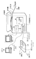
以下、図面を参照して本発明の実施の形態について詳細に説明する。図1乃至図4は本発明の第1の実施の形態に係り、図1は第1の実施の形態に係る内視鏡装置を含む内視鏡システムの全体を示す説明図、図2は内視鏡装置の回路構成を示すブロック図、図3はジョイスティックの動作範囲を説明するための説明図、図4は第1の実施の形態の動作を説明するための説明図である。
【0026】
本実施の形態は、ジョイスティックからの角度信号を停止させるべき中立位置の不感帯範囲を狭くすることによって、操作精度を向上させるようにしたものである。
【0027】
内視鏡制御ユニット1は、内視鏡3を収納する収納部4を備えている。内視鏡3は挿入部2を有し、挿入部2の先端部5は、湾曲自在である。内視鏡制御ユニット1には、CCU6、制御回路7及びモータ駆動回路8が構成されている。制御回路7は、内視鏡制御ユニット1の各部を制御する。
【0028】
内視鏡3の先端部5にはCCD28(図2参照)が設けられており、CCD28は被写体の光学像を光電変換して、カメラコントロールユニット(以下、CCUという)6に出力する。CCU6は、制御回路7に制御されて、入力された信号をモニタ表示するために標準的な映像信号に変換するようになっている。
【0029】
CCU6からの映像信号はケーブルを介してモニタ9に供給される。モニタ9は、入力された映像信号に基づいて、表示画面上に内視鏡画像を映出するようになっている。
【0030】
汎用PC16と制御回路7とは例えばRS232CやUSB等の所定のインターフェースケーブルを介して接続されている。汎用PC16には画像処理ソフトが内蔵されており、汎用PC16を操作することで制御回路7を介して、モニタ9に表示する内視鏡画像に所定の画像処理を施すことができるようになっている。
【0031】
図2に示すように、挿入部2には複数の牽引用ワイヤ28が配設されている。牽引用ワイヤ28は、一端が挿入部2の所定位置に固定されており、各牽引用ワイヤ28を適宜牽引することによって、挿入部2の先端部5は湾曲操作されるようになっている。各引用ワイヤ28は、複数のモータ27によって牽引されるようになっている。各モータ27は、モータ駆動回路8によって駆動されて牽引用ワイヤ28を牽引する。モータ駆動回路8は、制御回路7に制御されて、モータ27の駆動を制御するようになっている。
【0032】
本実施の形態においては、湾曲操作の遠隔操作手段として、ジョイスティック12が内蔵された操作リモコン11を用いるようになっている。操作リモコン11の上面からは、操作者の操作によって前後左右に傾斜自在なジョイスティック12の湾曲レバー13が立設されている。湾曲レバー13は、操作者によるレバー操作が行われていない場合には、図示しないバネの付勢力によって、所定の中立位置近傍に自動復帰するようになっている。
【0033】
図2に示すように、ジョイスティック12は、湾曲レバー13の左右方向の傾斜に対応して抵抗値が変化する可変抵抗器18と、湾曲レバー13の前後方向の傾斜に対応して抵抗値が変化する可変抵抗器19とを有している。可変抵抗器18は、湾曲レバー13の左右方向の傾斜角に対応したレベルのJ/SR/L信号を出力し、可変抵抗器19は、湾曲レバー13の前後方向の傾斜角に対応したレベルのJ/SU/D信号を出力する。
【0034】
可変抵抗器18,19からの出力は、操作リモコン11に内蔵されたリモコン回路21のCPU14に供給されるようになっている。CPU14はA/D変換器(A/D)22,23を有しており、A/D22,23によって、J/SR/L信号及びJ/SU/D信号はディジタル信号に変換されてCPU14に取込まれる。
【0035】
CPU14は、取込んだJ/SR/L信号及びJ/SU/D信号を、位置情報として出力する。図1の例では、操作リモコン11と制御回路7は、RS232C規格等のリモコンケーブル15によって接続されており、リモコン回路21は、RS232Cドライバ25を介して制御回路7に位置情報を出力する。
【0036】
本実施の形態においては、CPU14は、J/SR/L信号及びJ/SU/D信号を監視することで、湾曲レバー13が自動復帰によって中立位置に復帰したか否かを判断する。そして、CPU14は、中立位置に復帰したと判断した場合には、そのときのJ/SR/L信号及びJ/SU/D信号を中立位置における位置情報としてメモリ24に記憶させるようになっている。
【0037】
更に、CPU14は、メモリ24に記憶させた中立位置を中心にして一定範囲内に不感帯を設定するようになっている。そして、CPU14は、J/SR/L信号及びJ/SU/D信号によって、湾曲レバー13の傾斜が不感帯の範囲内であると判断した場合には、制御回路7への位置情報の送信を停止するようになっている。
【0038】
制御回路7は、リモコンケーブル15を介して位置情報が与えられ、位置情報に基づいてモータ駆動回路8を制御することにより、先端部5を位置情報に基づく湾曲角度で湾曲させるようになっている。
【0039】
次に、このように構成された実施の形態の動作について図3及び図4を参照して説明する。
【0040】
いま、操作者が内視鏡3挿入部2の先端部5を湾曲操作するものとする。操作者は操作リモコン11に立設されている湾曲レバー13によって湾曲操作を行う。即ち、操作者は先端部5を湾曲させたい方向に応じた向きに湾曲レバー13を傾斜させると共に、その傾斜角を湾曲させた角度に応じて傾斜させる。
【0041】
湾曲レバー13の傾斜操作によって、ジョイスティック12の可変抵抗器18,19の抵抗値が変化し、傾斜角に応じたレベルのJ/SR/L信号及びJ/SU/D信号がリモコン回路21のCPU14に供給される。CPU14は、A/D22,23によってこれらの信号を取込み、位置情報として出力する。
【0042】
リモコン回路21からの位置情報はリモコンケーブル15を介して内視鏡制御ユニット1内の制御回路7に供給される。制御回路7は、位置情報に基づいてモータ駆動回路8を制御する。これにより、モータ駆動回路8は、位置情報に基づいてモータ27を駆動して、牽引用ワイヤ28を適宜牽引する。これにより、挿入部2の先端部5は、位置情報に応じた方向及び湾曲角度で湾曲する。
【0043】
ここで、操作者がジョイスティック12の湾曲レバー13から手を放すものとする。そうすると、ジョイスティック12の湾曲レバー13は、図示しないバネの付勢力によって、図3に示す中立位置近傍に傾斜角が変化する。この場合には、湾曲レバー13は、バネ等のばらつきに応じたばらつき範囲内のいずれかの位置に自動復帰する。なお、図3に示すように、理想的な中立位置は、全操作範囲(湾曲レバー13の最大傾斜角の範囲)の中央であり、自動復帰位置は、中立位置前後の所定のばらつき範囲内である。
【0044】
CPU14は、ジョイスティック12の出力から、湾曲レバー13が自動復帰位置に復帰したことを検出すると、そのときの位置情報をメモリ24に記憶させる。そして、CPU14は、記憶させた位置情報の前後に所定範囲の不感帯を設定する。自動復帰位置に復帰したかどうかの検出は、例えば、可変抵抗器18,19の電圧が数秒間変化しないかどうかをCPU14で判断することで行う。
【0045】
本発明では自動復帰毎に、復帰した位置情報をリモコン回路12で記憶し、記憶した位置を軸に一定範囲内に不感帯を設定する。例えば、CPU14は、復帰位置が図4のA位置である場合には、このA位置を中心として曲線矢印にて示すA不感帯を設定する。また、例えば、復帰位置が図4のB位置である場合には、このB位置を中心として曲線矢印にて示すB不感帯を設定する。
【0046】
CPU14は、ジョイスティック12からのJ/SR/L信号及びJ/SU/D信号を監視して、湾曲レバー13の傾斜がメモリ24に記憶させている復帰位置に基づく不感帯の範囲内にあるか否かを判断する。そして、CPU14は、湾曲レバー13の傾斜が不感帯の範囲内であると判断した場合には、制御回路7ヘの位置情報の送信を停止する。
【0047】
いま、湾曲レバー13が自動復帰した後に、操作者が湾曲レバー13に手を触れていないものとする。この場合には、湾曲レバー13の傾斜は不感帯の範囲内である。従って、リモコン回路21からは制御回路7に位置情報が送信されない。制御回路7では、位置情報が受信されないので、制御回路7において、位置情報に基づく制御は行われない。
【0048】
ここで、操作者が先端部5の湾曲操作のために湾曲レバー13を操作するものとする。この場合には、操作者は、設定されている不感帯を越えるように湾曲レバー13を傾斜させる。そうすると、CPU14は、受信したJ/SR/L信号及びJ/SU/D信号から湾曲レバー13が不感帯の範囲外に傾斜したことを検出して、J/SR/L信号及びJ/SU/D信号に基づく位置情報の送信を再開する。この場合には、従来例のように、バネ等のばらつきを考慮した広い不感帯が設定するようにはなっていないので、操作者は、比較的小さい傾斜角のレバー操作で、湾曲を指示することができる。
【0049】
これにより、制御回路7は、位置情報の受信を再開し、モータ駆動回路8の制御等の位置情報に基づく制御を再開する。
【0050】
このように本実施の形態においては、制御回路7は、操作者がジョイスティック12の湾曲レバー13を操作していない場合には、湾曲操作に伴う制御を行う必要はない。従って、制御回路7は、位置情報を処理していた時間で、汎用PC16との通信や画像処理等の別処理を行なうことが可能となる。
【0051】
しかも、従来例のように、バネ等のばらつきを考慮して広い不感帯を設定する場合と異なり、不感帯の範囲を狭くすることができることから、微小な傾斜角のレバー操作によって湾曲を指示することができ、より高精度の操作性を得ることができる。
【0052】
また、自動復帰毎の位置情報を用いて中立位置及び不感帯を設定し直しているので、バネ等のばらつきが大きい場合でも狭い不感帯の範囲での利用が可能であり、自動復帰する位置が大きくばらつくような中立位置の精度が低い安価なジョイスティックに適用することができ、コストを抑制することができる。
【0053】
また、湾曲レバー13が不感帯の範囲内に位置する場合には、位置情報をジョイスティック12から送信しないので、送信及び処理回路を停止することができる。即ち、ジョイスティック12を操作していない期間の消費電力を低減させることが可能である。
【0054】
なお、上記実施の形態においては、操作リモコンはジョイスティックの操作に基づくアナログ信号を位置情報に変換した後に制御回路に出力するようになっているが、位置情報への変換機能等を内視鏡制御ユニット側に設けるようにしてもよい。即ち、リモコン回路21を内視鏡制御ユニット側に設けて、ジョイスティックからのアナログ信号をこのリモコン回路に伝達するようにすればよい。この場合には、既存のジョイスティックを利用した装置を構成することができる。
【0055】
図5乃至図図7は本発明の第2の実施の形態に係り、図5は第2の実施の形態に係る内視鏡装置を含む内視鏡システムの全体を示す説明図、図6は図5中の操作リモコンの内ジョイスティックの構成を具体的に示す説明図、図7は動作を説明するためのフローチャートである。図5において図1と同一の構成要素には同一符号を付して説明を省略する。
【0056】
本実施の形態は内視鏡制御ユニット1に代えて内視鏡制御ユニット45を採用し、操作リモコン11に代えて操作リモコン41を採用した点が第1の実施の形態と異なる。
【0057】
内視鏡制御ユニット45は制御回路7及びモータ駆動回路8に夫々代えて制御回路43及びモータ駆動回路44を採用した点が内視鏡制御ユニット1と異なる。また、操作リモコン41は、ジョイスティック12に代えてジョイスティック31を採用し、CPU14に代えてCPU42を採用した点が操作リモコン11と異なる。
【0058】
図6はジョイスティック31の断面を示している。湾曲レバー13は、前後左右方向に回動自在な球部34に植設され、操作リモコン41の筐体上面33から露出して設けられる。ジョイスティック31は、湾曲レバー13の左右方向の傾斜に対応して抵抗値が変化する可変抵抗器(図2参照)と、湾曲レバー13の前後方向の傾斜に対応して抵抗値が変化する可変抵抗器とを有しており、湾曲レバー13の前後及び左右方向の傾斜角に対応したレベルのアナログ信号をCPU42に出力するようになっている。また、図示しないばね等によって中立位置に自動復帰するように付勢されている。
【0059】
本実施の形態においては、ジョイスティック31は、球部34の下側に、タクタイルスイッチ35が設けられている。球部34は前後左右方向に回動自在なだけでなく、湾曲レバー13の軸方向への押し下げ操作によって、軸方向に移動することができるようになっている。
【0060】
球部34は、図示しないばね等によって上方向に付勢されており、湾曲レバー13の押し下げ操作が行われた場合にのみ軸に沿って下方向に移動して、底部分でタクタイルスイッチ35を押し下げてオンにすることができるようになっている。タクタイルスイッチ35は、球部34が押し下げられた場合にのみオン信号をCPU42に出力するようになっている。また、図示しないばね等によって中立位置に自動復帰するように付勢されている。
【0061】
CPU42は、湾曲レバー13の前後左右方向の傾斜角に応じたレベルの位置情報をリモコンケーブル15を介して制御回路43に出力すると共に、タクタイルスイッチ35のオン信号をモードの切換え信号として制御回路43に出力する。
【0062】
制御回路43は、図1の制御回路7と同様に、内視鏡制御ユニット45の各部を制御することができるようになっている。また、制御回路43は、システムコントロールマイコン(又はCPU)46を内蔵しており、湾曲レバー13の傾斜角に応じて、挿入部2の先端部5の湾曲角度を制御するようにモータ駆動回路8を制御することができるようになっている。更に、本実施の形態においては、制御回路43のCPU46は、湾曲レバー13の傾斜角に応じて湾曲角度を制御する位置制御モードだけでなく、湾曲レバー13の傾斜角とモータ27(図2参照)の回転速度とを比例させる速度制御モードを実行することができるようになっている。なお、湾曲方向は、いずれのモードでも湾曲レバー13の傾斜方向に一致させる。
【0063】
そして、本実施の形態においては、制御回路43のCPU46は、タクタイルスイッチ35のオン信号に基づく切換え信号によって、これらのモードを切換えるようになっている。即ち、CPU46は、位置制御モード時において切換え信号を受信すると共に、切換え信号の受信後に湾曲レバー13が中立位置に復帰したことを位置情報によって検出すると、位置制御モードから速度制御モードヘの切換え命令をモータ駆動回路44に送信する。また、CPU46は、速度制御モード時において切換え信号を受信すると、速度制御モードから位置制御モードへの切換え命令をモータ駆動回路44に送信する。
【0064】
モータ駆動回路44は、モータ駆動制御マイコン(CPU)47が内蔵されている。モータ駆動回路8は、CPU47において制御回路43からのモードの切換え命令を受信する。
【0065】
モータ駆動回路44のCPU47は、モード切換え命令を受信すると、それまでのモードによる最後の状態を維持し、それ以後切換え後のモードを実行するようにプログラムを切換えるようになっている。
【0066】
例えば、位置制御モード時に切換え命令を受信すると、モータ駆動制御マイコン47は、先端部5の湾曲状態(湾曲角度)を保持しつつ、以後湾曲レバー13の傾斜角とモータ27の回転速度が比例する速度制御モードに内部プログラムを切換える。
【0067】
逆に、速度制御モード時に切換え命令を受信すると、モータ駆動制御マイコン47は、以後湾曲レバー13の傾斜角と内視鏡の湾曲角度を比例させる位置制御モードに、プログラムを切換えるようになっている。
【0068】
なお、速度制御モードから位置制御モードへの切換え時には、湾曲レバー13がセンター位置に戻っていることが多いものと考えられる。この場合には、モード切換え時点における湾曲は、位置制御モードになることでストレート状態に戻る。湾曲がストレート状態に戻る際の速度が速い場合には、メカ的な負担が大きくなり、また、映像が急に流れて観察位置の把握が困難になるので、ストレート状態への復帰速度は、比較的遅いほうがよい。
【0069】
そこで、モータ駆動制御マイコン47は、速度制御モードから位置制御モードに切換える場合には、モータ27の回転速度を比較的遅くして、ストレート状態又はモード切換え時点における湾曲レバー13の傾斜角に応じた湾曲角度まではゆっくりと復帰させるようになっている。なお、この場合における湾曲スピードを任意に選択可能にし、最適な湾曲スピードに制御することにより、耐久性及び使い勝手を向上させることができる。
【0070】
CPU47は、速度制御モード時においては、ジョイスティックの傾斜角に比例して出力される位置情報(数値)を積分した値に基づいてモータ27の速度制御を行うようになっている。
【0071】
なお、位置制御モード時のレバー傾斜角と湾曲角度の関係、速度制御モード時のレバー傾斜角とモータの回転速度は、必づしも正比例でなくてもよく、例えば指数関数、又はその他の計算式によりレバー傾斜角の増減で湾曲角度、回転速度が増減するようにしてもよい。
【0072】
なお、速度制御モードにおけるモータの回転速度Vm と回転角θm は、例えば、下記(1),(2)式によって表される。
【0073】

【0074】
次に、このように構成された実施の形態の動作について図7のフローチャートを参照して説明する。
【0075】
いま、操作者が挿入部2の先端部5を湾曲操作するものとする。なお、この時点では、制御回路43のCPU46は、位置制御モードに設定しているものとする。操作者は操作リモコン41に内蔵されているジョイスティック31の湾曲レバー13を傾斜させて湾曲操作を行う。
【0076】
操作者が湾曲レバー13を傾斜させると、傾斜角に応じたレベルの信号がCPU42に与えられる。CPU42は入力された信号に基づく位置情報を発生し、リモコンケーブル15を介して制御回路43に送信する。
【0077】
制御回路43のCPU46は、受信した位置情報に基づいてモータ駆動回路44を制御する(ステップS2 )。これにより、モータ駆動回路44のCPU47は、位置情報に応じてモータ27をサーボ制御し(ステップS3 )、モータを所定速度で駆動して先端部5を傾斜させる(ステップS4 )。
【0078】
ここで、操作者が湾曲速度を小さくすることにより、湾曲角度の微調整を行うものとする。この場合には、操作者は湾曲レバー13を押下する。この操作によってジョイスティック31のタクタイルスイッチ35がオンとなり、CPU42は切換え信号を発生する。切換え信号は制御回路43のCPU46によって受信される。
【0079】
これにより、CPU46はステップS1 からステップS5 に処理を移行して、モータ駆動回路44に湾曲状態を保持させる。更に、操作者が湾曲レバー13を中立位置まで戻したり、湾曲レバーから指を離して中立位置に自動復帰させると、制御回路43のCPU46は、位置情報によって湾曲レバー13が中立位置に位置することを検出し(ステップS7 )、位置制御モードから速度制御モードへの切換え命令をモータ駆動回路44のCPU47に出力する。
【0080】
モータ駆動回路44のCPU47は、湾曲レバー13の湾曲角度に応じて湾曲速度が制御される速度制御モードS6 によって、モータ27を駆動制御する。操作者が比較的小さい角度で湾曲レバー13を傾斜させると、モータ駆動回路44は、モータサーボによって(ステップS3 )、湾曲レバー13の傾斜角に応じた低速で先端部5を湾曲させる(ステップS4 )。こうして、先端部5の湾曲角度を微調整することができる。
【0081】
次に、操作者が元の位置制御モードに戻すために、湾曲レバー31を軸方向に押下するものとする。そうすると、タクタイルスイッチ35がオンとなって、制御回路43のCPU46は、切換え信号を受信する。制御回路43は、速度制御モードから位置制御モードへの切換え命令をモータ駆動回路44に出力する。
【0082】
モータ駆動回路44は、切換え命令出力時における湾曲レバー13の傾斜角に相当する湾曲角度まで、ゆっくりと先端部5の湾曲角度を変化させる。一般的な使用法では、位置制御モードへの切換え時点においては、ばねの付勢により湾曲レバー13は略中立位置に位置するものと考えられるので、モータ駆動回路44は、先端部5をストレート状態にゆっくりと戻す。
【0083】
切換え命令出力時のレバー13傾斜角に相当する角度まで選択部5の湾曲角度が変化すると、以後、通常の速度で、湾曲レバー13の傾斜位置に対応させて湾曲させる位置制御が行われる。
【0084】
このように、本実施の形態においては、操作者が実際の湾曲角度の把握しやすい位置制御方式と、微調整が可能で且つ操作者が湾曲スピードを任意に変えることが可能な速度制御方式を、操作者が簡単な操作で任意に切り替えて使用することができる。
【0085】
なお、第2の実施の形態においては、湾曲レバーが中立位置に復帰したことを制御回路43内のCPU46において判断しており、CPU46は、湾曲レバーが中立位置に復帰した後に、切換え命令をモータ駆動回路44のCPU47に送信している。これに対し、湾曲レバーが中立位置に復帰したことを、モータ駆動回路44のCPU47において判断してもよい。即ち、この場合には、制御回路43内のCPU46は、切換え命令と共に、湾曲レバーの傾斜角に応じた情報をモータ駆動回路44内のCPU47に供給する。CPU47において、湾曲レバーが中立位置に復帰したことを検出した後、モードを切換えればよい。
【0086】
図8は本発明の第3の実施の形態に採用される動作フローを示すフローチャートである。図8において図7と同一の手順には同一符号を付して説明を省略する。
【0087】
本実施の形態におけるハードウェア構成は第2の実施の形態と同一である。
【0088】
本実施の形態は位置制御モードから速度制御モードへの切換え時において、湾曲レバーが中立位置に復帰しない場合でもモードの移行を行うようにさせたものである。
【0089】
図8は、湾曲レバー13の軸方向への押下から所定時間経過したか否かを判断するステップS8 を付加した点が図7の動作フローと異なる。
【0090】
このように構成された実施の形態においては、湾曲レバー13を軸方向に押下した後、プログラムで定めた一定時間経過しても湾曲レバー13がセンター位置に戻らない場合、制御回路43のシステムコントローマイコン46は、ステップS8 において、所定時間経過したことを検出すると、自動的に位置制御モードから速度制御モードへの切換え命令を出力する。
【0091】
これにより、モード切換え時点における先端部5の湾曲方向と、モード切換え後における先端部5の湾曲方向とが一致する場合においては、制御モードの切換え時において、スムーズな湾曲操作が可能となる。
【0092】
このように、本実施の形態においては、一方向を連続観察する場合等において、制御モードの切換えをスムーズに連続して行うことができ、作業手順を簡略化することができる。
【0093】
図9は本発明の第4の実施の形態を示すブロック図である。図9において図5と同一の構成要素には同一符号を付して説明を省略する。本実施の形態は第2及び第3の実施の形態に対して、湾曲ロック状態であることを操作者に認識可能にしたものである。
【0094】
内視鏡制御ユニット51は、湾曲ロック状態を示す表示機能を付加した点を除き、図5の内視鏡制御ユニット45と略同様の構成である。即ち、湾曲駆動装置68は、図2のモータ27及び牽引用ワイヤ28等に相当し、挿入部2の先端部5を湾曲駆動する。湾曲制御基板66は、図5のモータ駆動回路44に相当する機能を有し、操作リモコン41の操作に基づいて、位置制御モード及び速度制御モードを切換えながら、湾曲駆動装置68を制御する。
【0095】
CCU67は図5のCCU6と同様の構成である。システムコントロールマイコン61は、図5の制御回路43と同等の機能を有する。システムコントロールマイコン61はCPU62、ROM63、画像発生装置64及びスーパーインポーズ装置65によって構成されている。
【0096】
ROM63にはCPU62の動作プログラムが格納されている。CPU62は図5の制御回路43中のCPU46と同等の機能を有すると共に、切換え命令に応答して湾曲ロック状態に遷移したことを示す情報が湾曲制御基板66から与えられて、この情報に基づく表示命令を画像発生装置64に出力するようになっている。画像発生装置64は、湾曲ロック状態に伴う表示命令が入力されると、湾曲ロックを示す表示(文字又はグラフィック)の表示データを発生してスーパーインポーズ装置65に供給するようになっている。
【0097】
スーパーインポーズ装置65は、CCU67において作成された画像に、画像発生装置64からの表示データをスーパーインポーズして、モニタ9に出力するようになっている。
【0098】
このように構成された実施の形態においては、操作者が操作リモコン41の湾曲レバー13を押し下げると、タクタイルスイッチ(図6参照)がオンとなって、切換え信号がCPU62に供給されることは第2及び第3の実施の形態と同様である。CPU62は、切換え信号を受信すると、モードを切換えるための切換え命令を湾曲制御基板66に出力する。
【0099】
湾曲制御基板66は、モードを切換えに伴って、湾曲駆動装置68を制御して、先端部5の湾曲状態をロック(湾曲ロック)させる。本実施例においては、湾曲制御基板66は、湾曲ロック状態に遷移したことを示す情報をシステムコントロールマイコン61のCPU62に供給する。
【0100】
これにより、CPU62は表示命令を画像発生装置64に出力する。画像発生装置64によって、湾曲ロックを示す表示の表示データが発生して、スーパーインポーズ装置65に供給される。スーパーインポーズ装置65は、CCU67からの画像に湾曲ロックを示す表示データを重畳して、モニタ9に出力する。
【0101】
こうして、モニタ9の表示画面上には、湾曲ロックを示す表示69がスーパーインポーズされた画像が映出される。湾曲制御基板66によって湾曲ロックが解除されると、CPU62は、画像発生装置64に表示データの出力を停止させる命令を発する。これにより、モニタ9の表示画面からは湾曲ロックを示す表示69が消去される。
【0102】
このように、本実施の形態においては、湾曲ロック状態であることを示す表示をモニタ上に表示させることができ、操作者は容易に湾曲ロック状態を確認することができる。また、湾曲ロック状態であることを示す表示は、CCU67からの画像上にスーパーインポーズ表示されており、操作者は内視鏡画像から目を離すことなく、容易に湾曲ロック状態を確認することができる。
【0103】
なお、本実施の形態においては、湾曲制御基板66が湾曲ロック動作完了を示す信号をCPU62に出力することによって、CPU62が表示命令を発する例を説明したが、システムコントロールマイコン61において、湾曲ロック動作の完了を判断して表示命令を発するようにしてもよい。
【0104】
[付記]
(1) 挿入部の先端部を湾曲駆動する駆動手段と、
レバーの傾斜によって前記先端部を湾曲操作する操作部からの情報に基づいて前記駆動手段に前記先端部を湾曲駆動させると共に、前記レバーが中立位置に自動復帰する毎に中立位置を検出し、検出した中立位置から一定の範囲を前記駆動手段による前記先端部の湾曲駆動を禁止する不感帯に設定する制御手段とを具備したことを特徴とする内視鏡装置。
【0105】
(2) 挿入部の先端部を湾曲駆動する駆動手段と、
レバーの傾斜によって前記先端部を湾曲操作する操作部と、
前記操作部からの情報に基づいて、前記レバーの傾斜角に応じて前記先端部の湾曲角度を決定する位置制御モードと、前記レバーの傾斜角に応じて前記先端部の湾曲速度を決定する速度制御モードとを切換えて前記駆動手段に前記先端部を湾曲駆動させる制御手段とを具備したことを特徴とする内視鏡装置。
【0106】
(3) 前記操作部は、前記レバーの押下操作によって、前記位置制御モードと速度制御モードとの切換えを行うための信号を前記制御手段に出力することを特徴とする付記項2に記載の内視鏡装置。
【0107】
(4) 制御手段は、前記レバーの傾斜角に応じた値を積分することで、速度制御モードにおける速度を決定することを特徴とする付記項2に記載の内視鏡装置。
【0108】
(5) 前記制御手段は、前記レバーの押下操作後に、前記レバーが中立位置に復帰したことを検出することにより、前記位置制御モードから前記速度制御モードへの切換を行うことを特徴とする付記項3に記載の内視鏡装置。
【0109】
(6) 前記制御手段は、前記位置制御モードと前記速度制御モードとの切換え時には、切換え直前における前記先端部の湾曲状態を保持することを特徴とする付記項2に記載の内視鏡装置。
【0110】
(7) 前記制御手段が前記先端部の湾曲状態を保持していることを表示する表示手段を更に具備したことを特徴とする付記項6に記載の内視鏡装置。
【0111】
【発明の効果】
以上説明したように本発明によれば、ジョイスティックによる湾曲操作の操作性を向上させると共に、ジョイスティックによる湾曲操作の操作精度を向上させることができるという効果を有する。
【図面の簡単な説明】
【図1】本発明の第1の実施の形態に係る内視鏡装置を含む内視鏡システムの全体を示す説明図。
【図2】内視鏡装置の回路構成を示すブロック図。
【図3】ジョイスティックの動作範囲を説明するための説明図。
【図4】第1の実施の形態の動作を説明するための説明図。
【図5】第2の実施の形態に係る内視鏡装置を含む内視鏡システムの全体を示す説明図。
【図6】図5中の操作リモコンの内ジョイスティックの構成を具体的に示す説明図。
【図7】動作を説明するためのフローチャート。
【図8】本発明の第3の実施の形態に採用される動作フローを示すフローチャート。
【図9】本発明の第4の実施の形態を示すブロック図。
【符号の説明】
1…内視鏡制御ユニット、2…挿入部、3…内視鏡、5…先端部、6CCU、7…制御回路、8…モータ駆動回路、9…モニタ、11…操作リモコン、12…ジョイスティック、13…湾曲レバー。[0001]
BACKGROUND OF THE INVENTION
The present invention relates to an endoscope apparatus suitable for an apparatus that drives a distal end portion of an endoscope by using a joystick.
[0002]
[Prior art]
2. Description of the Related Art Conventionally, endoscopes in which a long and narrow endoscope is inserted into a body cavity or the like to observe a test site and perform various treatments have been widely used. Also in the industrial field, industrial endoscopes that can observe and inspect internal scratches and corrosion of boilers, turbines, engines, chemical plants, and the like are widely used.
[0003]
The endoscope apparatus has an elongated insertion portion including a bending portion that can be bent by a hand operation. The insertion portion is provided with a CCD or the like as an imaging means at the tip, and a camera control unit is provided on the hand side.
[0004]
Image information obtained by the CCD is transmitted to the camera control unit to generate a video signal. By supplying this video signal to a display device such as an LCD or CRT, an endoscopic image can be displayed.
[0005]
The bending operation of the insertion portion bending portion can be remotely operated by an operation remote controller. In other words, a bending drive motor that can be controlled by an operation remote controller is provided, and the bending portion can be remotely operated by pulling a wire disposed in the bending portion using the power of the motor. It has become.
[0006]
As such an operation remote controller, there is one disclosed in Japanese Patent Laid-Open No. 10-328131. In this proposal, a joystick is disclosed as an operation remote controller for bending operation. This proposal does not disclose a specific operation method of the joystick.
[0007]
Japanese Patent Laid-Open No. 5-207968 discloses a proposal for operating an electric bending insertion section removable from a processor control module with a joystick. In this proposal, it is shown that the position of the electric bending insertion portion is controlled by a joystick. It is also disclosed to “park” (curve lock) the curved shape electrically. In this proposal, there is no detailed description of a specific operation method such as operation of operation buttons for position control and bending lock.
[0008]
The joystick has a variable resistor whose resistance value changes according to the tilt angle of the lever, and can output an analog voltage value according to the tilt angle of the lever. Such a joystick is often used for position control as disclosed in JP-A-5-207968.
[0009]
[Problems to be solved by the invention]
In position control using a joystick, a method is conceivable in which the tilt angle of the lever is proportional to the amount of displacement of the controlled object. For example, there is an advantage that the operator can easily grasp the actual bending angle by making the inclination angle of the lever (curving lever) proportional to the bending angle of the distal end of the insertion portion.
[0010]
However, when it is desired to bend only by a small angle, the operation angle of the bending lever must also be small, and it is necessary for the operator to concentrate nerves on the fingertips, and the degree of work fatigue is large.
[0011]
Therefore, in order to improve the disadvantages of such position control, the output of the joystick is not treated as an analog value corresponding to the tilt angle of the lever, but as a signal indicating only the direction, and the curved portion is fixed in the direction in which the lever is tilted. A method of bending at a constant speed (constant speed bending control) has also been put into practical use. In addition, there is a system that switches between position control and constant speed bending control.
[0012]
In the constant speed bending control, since the operator cannot arbitrarily change the bending speed, the constant speed is often set to be slow and the operation is performed in a so-called slow mode. In the slow mode, the operability at the time of fine adjustment of the bending angle is high, but there is a disadvantage that it takes a long time to reach a desired bending angle. Conversely, when the bending speed is increased, the operability during fine adjustment is significantly reduced.
[0013]
Further, in the proposal of Japanese Patent Laid-Open No. 5-207968, when turning on the bending lock, the bending lock switch laid out at a position different from the joystick for performing the bending operation is operated. Therefore, in this proposal, it is not possible to lock the curve by one-handed operation.
[0014]
In general, it is not possible to confirm that the curve is locked, or it is general to confirm by turning on an LED in the vicinity of the switch. However, in order to confirm by turning on the LED or the like, it is necessary to keep an eye on the monitor on which the endoscopic image or the like is displayed, and the workability is poor.
[0015]
By the way, when the lever is not operated, the joystick automatically returns to the vicinity of the neutral position by the biasing force of the spring. However, there is a problem that the neutral position of the lever due to automatic return varies greatly depending on the accuracy of the spring and mechanical mechanism of the joystick.
[0016]
In view of this variation, a method of setting the vicinity of the neutral position as a dead zone and stopping the output of the position information signal when the lever is in the neutral position can be considered. However, in this case, the lever operation within a predetermined range near the neutral position is not effective, and there is a drawback that the bending operation cannot be performed unless the lever is tilted relatively large.
[0017]
On the other hand, if the position information is always transmitted without providing a dead zone, the position information is output from the joystick even when the lever is not operated. Therefore, in the controller that performs control using the position information of the joystick, the processing efficiency of the CPU is high. It will decline.
[0018]
For these reasons, it has been difficult to increase the operation accuracy of the joystick.
[0019]
The present invention has been made in view of such problems, and an object of the present invention is to provide an endoscope apparatus capable of improving the operability of a bending operation using a joystick.
[0020]
It is another object of the present invention to provide an endoscope apparatus that can improve the operation accuracy of a bending operation using a joystick.
[0021]
[Means for Solving the Problems]
According to the present inventionOf the first aspectThe endoscope apparatus includes an insertion portion, a driving means, one end connected to the insertion portion, the other end connected to the driving means, a traction means for bending the insertion portion by driving of the driving means, and an inclination of the lever Control means for causing the drive means to bend the insertion part via the traction means based on position information of the lever from an operation part for bending the insertion part. When it is determined that the lever is located in a dead zone within a certain range from the neutral position of the lever, transmission of the position information of the lever to the driving unit is stopped, and it is determined that the lever is tilted beyond the dead zone. When the lever position information is transmitted to the drive meansAs a control method for bending the insertion portion, a position control mode for determining a bending angle of the insertion portion according to the inclination angle of the lever, and a bending speed of the insertion portion according to the inclination angle of the lever A speed control mode for determining the position, and the control means switches the control method to either the position control mode or the speed control mode based on a switching signal from the operation unit. The control method is switched while maintaining the bending angle.
[0022]
The endoscope apparatus according to the second aspect of the present invention includes an insertion portion, a driving means, one end connected to the insertion portion, and the other end connected to the driving means, and the insertion by driving the driving means. Traction means for bending the portion, and control means for causing the drive means to bend the insertion portion via the traction means based on position information of the lever from an operation portion for bending the insertion portion by tilting the lever. And the control means stops transmitting the position information of the lever to the driving means when it is determined that the lever is located in a dead zone within a certain range from the neutral position of the lever, and the lever Is determined to be tilted beyond the dead zone, the position information of the lever is transmitted to the driving means, and as a control method for bending the insertion portion, according to the tilt angle of the lever A position control mode for determining a bending angle of the insertion portion, and a speed control mode for determining a bending speed of the insertion portion in accordance with an inclination angle of the lever, wherein the control means is based on a switching signal from the operation portion. When the control method is switched between the position control mode and the speed control mode, the bending angle of the insertion portion is stored, and the driving means is controlled so that the insertion portion is straight. From the above, the drive unit is controlled so that the insertion portion has the bending angle, and the control method is switched.
[0025]
DETAILED DESCRIPTION OF THE INVENTION
Hereinafter, embodiments of the present invention will be described in detail with reference to the drawings. 1 to 4 relate to a first embodiment of the present invention. FIG. 1 is an explanatory diagram showing the entire endoscope system including an endoscope apparatus according to the first embodiment. FIG. FIG. 3 is an explanatory diagram for explaining the operation range of the joystick, and FIG. 4 is an explanatory diagram for explaining the operation of the first embodiment.
[0026]
In this embodiment, the operation accuracy is improved by narrowing the dead zone range of the neutral position where the angle signal from the joystick should be stopped.
[0027]
The
[0028]
The
[0029]
The video signal from the
[0030]
The general-
[0031]
As shown in FIG. 2, a plurality of pulling
[0032]
In the present embodiment, an operation remote controller 11 having a built-in joystick 12 is used as a remote operation means for bending operation. From the upper surface of the operation remote controller 11, a bending
[0033]
As shown in FIG. 2, the joystick 12 has a
[0034]
Outputs from the
[0035]
The
[0036]
In the present embodiment, the
[0037]
Further, the
[0038]
The
[0039]
Next, the operation of the embodiment configured as described above will be described with reference to FIGS.
[0040]
Now, it is assumed that the operator performs a bending operation on the
[0041]
By the tilting operation of the bending
[0042]
Position information from the remote control circuit 21 is supplied to the
[0043]
Here, it is assumed that the operator releases his / her hand from the bending
[0044]
When the
[0045]
In the present invention, for each automatic return, the returned position information is stored in the remote control circuit 12, and a dead zone is set within a certain range around the stored position. For example, when the return position is the A position in FIG. 4, the
[0046]
The
[0047]
It is assumed that the operator does not touch the bending
[0048]
Here, it is assumed that the operator operates the bending
[0049]
As a result, the
[0050]
Thus, in the present embodiment, when the operator does not operate the bending
[0051]
In addition, unlike the conventional example, in which a wide dead zone is set in consideration of variations in springs and the like, the dead zone range can be narrowed, so that bending can be instructed by operating a lever with a small inclination angle. More accurate operability can be obtained.
[0052]
In addition, since the neutral position and dead zone are reset using the position information for each automatic return, even if there is a large variation in springs, etc., it can be used in a narrow dead zone, and the automatic return position varies greatly. This can be applied to an inexpensive joystick having a low accuracy of the neutral position, and the cost can be suppressed.
[0053]
Further, when the bending
[0054]
In the above embodiment, the operation remote controller converts the analog signal based on the operation of the joystick into position information and then outputs it to the control circuit. However, the function for converting to position information is controlled by the endoscope. It may be provided on the unit side. That is, the remote control circuit 21 may be provided on the endoscope control unit side so that an analog signal from the joystick is transmitted to the remote control circuit. In this case, an apparatus using an existing joystick can be configured.
[0055]
FIG. 5 to FIG. 7 relate to a second embodiment of the present invention, FIG. 5 is an explanatory view showing the entire endoscope system including the endoscope apparatus according to the second embodiment, and FIG. FIG. 7 is an explanatory diagram specifically showing the configuration of the inner joystick of the operation remote controller in FIG. 5, and FIG. 7 is a flowchart for explaining the operation. In FIG. 5, the same components as those of FIG.
[0056]
The present embodiment is different from the first embodiment in that an endoscope control unit 45 is employed instead of the
[0057]
The endoscope control unit 45 is different from the
[0058]
FIG. 6 shows a cross section of the
[0059]
In the present embodiment, the
[0060]
The
[0061]
The
[0062]
The control circuit 43 can control each part of the endoscope control unit 45 in the same manner as the
[0063]
In this embodiment, the
[0064]
The motor drive circuit 44 incorporates a motor drive control microcomputer (CPU) 47. The
[0065]
When the
[0066]
For example, when a switching command is received in the position control mode, the motor
[0067]
Conversely, when a switching command is received in the speed control mode, the motor
[0068]
It should be noted that the bending
[0069]
Therefore, when switching from the speed control mode to the position control mode, the motor
[0070]
In the speed control mode, the
[0071]
It should be noted that the relationship between the lever tilt angle and the bending angle in the position control mode and the lever tilt angle in the speed control mode and the motor rotation speed do not necessarily have to be directly proportional, for example, an exponential function or other calculation. The bending angle and rotational speed may be increased or decreased by increasing or decreasing the lever tilt angle according to the equation.
[0072]
Note that the rotational speed Vm and the rotational angle θm of the motor in the speed control mode are expressed by the following equations (1) and (2), for example.
[0073]
[0074]
Next, the operation of the embodiment configured as described above will be described with reference to the flowchart of FIG.
[0075]
Now, it is assumed that the operator performs a bending operation on the
[0076]
When the operator tilts the bending
[0077]
The
[0078]
Here, it is assumed that the bending angle is finely adjusted by the operator reducing the bending speed. In this case, the operator presses the bending
[0079]
As a result, the
[0080]
The
[0081]
Next, it is assumed that the bending
[0082]
The motor drive circuit 44 slowly moves to a bending angle corresponding to the inclination angle of the bending
[0083]
When the bending angle of the
[0084]
As described above, in this embodiment, a position control method that allows the operator to easily grasp the actual bending angle and a speed control method that allows fine adjustment and allows the operator to arbitrarily change the bending speed. The operator can switch between them with a simple operation.
[0085]
In the second embodiment, the
[0086]
FIG. 8 is a flowchart showing an operation flow employed in the third embodiment of the present invention. In FIG. 8, the same steps as those in FIG.
[0087]
The hardware configuration in the present embodiment is the same as that in the second embodiment.
[0088]
In this embodiment, when the position control mode is switched to the speed control mode, the mode is changed even when the bending lever does not return to the neutral position.
[0089]
FIG. 8 differs from the operation flow of FIG. 7 in that step S8 for determining whether or not a predetermined time has elapsed since the bending
[0090]
In the embodiment configured as described above, if the bending
[0091]
As a result, when the bending direction of the
[0092]
As described above, in the present embodiment, when continuously observing one direction, the control mode can be switched smoothly and continuously, and the work procedure can be simplified.
[0093]
FIG. 9 is a block diagram showing a fourth embodiment of the present invention. In FIG. 9, the same components as those in FIG. This embodiment makes it possible for the operator to recognize that it is in a curved lock state compared to the second and third embodiments.
[0094]
The endoscope control unit 51 has substantially the same configuration as the endoscope control unit 45 of FIG. 5 except that a display function indicating a bending lock state is added. That is, the bending
[0095]
The
[0096]
The
[0097]
The superimposing
[0098]
In the embodiment configured as described above, when the operator depresses the bending
[0099]
The bending
[0100]
As a result, the
[0101]
In this way, an image on which the
[0102]
As described above, in the present embodiment, a display indicating the bending lock state can be displayed on the monitor, and the operator can easily confirm the bending lock state. In addition, a display indicating that the bending lock state is displayed is superimposed on the image from the
[0103]
In this embodiment, the example in which the
[0104]
[Appendix]
(1) driving means for driving the distal end of the insertion portion to bend;
Based on the information from the operation unit that bends the tip by lever inclination, the driving means drives the tip to bend, and the neutral position is detected and detected each time the lever automatically returns to the neutral position. An endoscope apparatus comprising: a control unit that sets a certain range from the neutral position to a dead zone that prohibits the driving of the tip portion from being bent by the driving unit.
[0105]
(2) driving means for driving the distal end of the insertion portion to bend;
An operation unit for bending the tip by tilting the lever;
A position control mode for determining the bending angle of the tip according to the tilt angle of the lever based on information from the operation unit, and a speed for determining the bending speed of the tip according to the tilt angle of the lever An endoscope apparatus comprising: control means for switching the control mode to cause the driving means to drive the bending of the distal end portion.
[0106]
(3) In the
[0107]
(4) The endoscope apparatus according to
[0108]
(5) The control means switches from the position control mode to the speed control mode by detecting that the lever has returned to the neutral position after the lever is pressed.
[0109]
(6) The endoscope apparatus according to
[0110]
(7) The endoscope apparatus according to
[0111]
【The invention's effect】
As described above, according to the present invention, it is possible to improve the operability of the bending operation using the joystick and to improve the operation accuracy of the bending operation using the joystick.
[Brief description of the drawings]
FIG. 1 is an explanatory diagram showing the entire endoscope system including an endoscope apparatus according to a first embodiment of the present invention.
FIG. 2 is a block diagram showing a circuit configuration of the endoscope apparatus.
FIG. 3 is an explanatory diagram for explaining an operation range of a joystick.
FIG. 4 is an explanatory diagram for explaining the operation of the first embodiment;
FIG. 5 is an explanatory diagram showing an entire endoscope system including an endoscope apparatus according to a second embodiment.
6 is an explanatory diagram specifically showing a configuration of an inner joystick of the operation remote controller in FIG. 5. FIG.
FIG. 7 is a flowchart for explaining the operation.
FIG. 8 is a flowchart showing an operation flow employed in the third embodiment of the present invention.
FIG. 9 is a block diagram showing a fourth embodiment of the present invention.
[Explanation of symbols]
DESCRIPTION OF
Claims (7)
駆動手段と、
一端が前記挿入部に、他端が前記駆動手段に接続され、前記駆動手段の駆動により前記挿入部を湾曲させる牽引手段と、
レバーの傾斜によって前記挿入部を湾曲操作する操作部からの前記レバーの位置情報に基づいて前記牽引手段を介して前記駆動手段に前記挿入部を湾曲させる制御手段と、
を具備し、
前記制御手段は、前記レバーの中立位置から一定の範囲の不感帯に前記レバーが位置すると判断したとき、前記レバーの位置情報を前記駆動手段に伝達することを停止し、前記レバーが前記不感帯を超えて傾斜されたと判断したとき、前記レバーの位置情報を前記駆動手段に伝達し、
前記挿入部を湾曲させるための制御方式として、前記レバーの傾斜角に応じて前記挿入部の湾曲角度を決定する位置制御モードと、前記レバーの傾斜角に応じて前記挿入部の湾曲速度を決定する速度制御モードとを備え、
当該制御手段は、前記操作部からの切換え信号に基づいて前記制御方式を前記位置制御モードと前記速度制御モードとのいずれかに切換えるとき、前記挿入部の湾曲角度を維持して前記制御方式を切換える
ことを特徴とする内視鏡装置。An insertion part;
Driving means;
One end is connected to the insertion portion, the other end is connected to the driving means, and the pulling means is configured to bend the insertion portion by driving the driving means;
Control means for causing the drive means to bend the insertion part via the traction means based on position information of the lever from an operation part for bending the insertion part by tilting the lever;
Comprising
When the control means determines that the lever is located in a dead band within a certain range from the neutral position of the lever, the control means stops transmitting the position information of the lever to the driving means, and the lever exceeds the dead band. The position information of the lever is transmitted to the driving means ,
As a control method for bending the insertion portion, a position control mode for determining the bending angle of the insertion portion according to the inclination angle of the lever, and a bending speed of the insertion portion according to the inclination angle of the lever. Speed control mode to
The control means maintains the bending angle of the insertion portion and switches the control method when switching the control method to either the position control mode or the speed control mode based on a switching signal from the operation unit. Switch
An endoscope apparatus characterized by that .
ことを特徴とする請求項1に記載の内視鏡装置。The control means detects the neutral position every time the lever returns to the neutral position, and sets a certain range from the detected neutral position as a dead zone for prohibiting the bending of the insertion portion by the driving means. The endoscope apparatus according to claim 1.
ことを特徴とする請求項1または2に記載の内視鏡装置。The control means controls the driving means so that the insertion portion is straight when the lever is in a neutral position, and then the insertion portion is straight when the lever is tilted within a dead zone. It controls so that it may maintain. The endoscope apparatus according to claim 1 or 2 characterized by things.
駆動手段と、
一端が前記挿入部に、他端が前記駆動手段に接続され、前記駆動手段の駆動により前記挿入部を湾曲させる牽引手段と、
レバーの傾斜によって前記挿入部を湾曲操作する操作部からの前記レバーの位置情報に基づいて前記牽引手段を介して前記駆動手段に前記挿入部を湾曲させる制御手段と、
を具備し、
前記制御手段は、前記レバーの中立位置から一定の範囲の不感帯に前記レバーが位置すると判断したとき、前記レバーの位置情報を前記駆動手段に伝達することを停止し、前記レバーが前記不感帯を超えて傾斜されたと判断したとき、前記レバーの位置情報を前記駆動手段に伝達し、
前記挿入部を湾曲させるための制御方式として、前記レバーの傾斜角に応じて前記挿入部の湾曲角度を決定する位置制御モードと、前記レバーの傾斜角に応じて前記挿入部の湾曲速度を決定する速度制御モードとを備え、
当該制御手段は、前記操作部からの切換え信号に基づいて前記制御方式を前記位置制御モードと前記速度制御モードとのいずれかに切換えるとき、前記挿入部の湾曲角度を記憶しておき、前記挿入部がストレートになるように前記駆動手段を制御してから前記挿入部が前記湾曲角度となるように前記駆動手段を制御し、前記制御方式を切換える
ことを特徴とする内視鏡装置。 An insertion part;
Driving means;
One end is connected to the insertion portion, the other end is connected to the driving means, and the pulling means is configured to bend the insertion portion by driving the driving means;
Control means for causing the drive means to bend the insertion part via the traction means based on position information of the lever from an operation part for bending the insertion part by tilting the lever;
Comprising
When the control means determines that the lever is located in a dead band within a certain range from the neutral position of the lever, the control means stops transmitting the position information of the lever to the driving means, and the lever exceeds the dead band. The position information of the lever is transmitted to the driving means,
As a control method for bending the insertion portion, a position control mode for determining the bending angle of the insertion portion according to the inclination angle of the lever, and a bending speed of the insertion portion according to the inclination angle of the lever. Speed control mode to
The control means stores the bending angle of the insertion portion when switching the control method to either the position control mode or the speed control mode based on a switching signal from the operation portion, The drive means is controlled so that the section is straight, and then the drive means is controlled so that the insertion section has the bending angle, and the control method is switched.
An endoscope apparatus characterized by that .
ことを特徴とする請求項4に記載の内視鏡装置。 The control means detects the neutral position every time the lever returns to the neutral position, and sets a certain range from the detected neutral position as a dead zone for prohibiting the bending of the insertion portion by the driving means.
The endoscope apparatus according to claim 4 .
ことを特徴とする請求項4または5に記載の内視鏡装置。 The control means controls the driving means so that the insertion portion is straight when the lever is in a neutral position, and then the insertion portion is straight when the lever is tilted within a dead zone. Control to maintain
The endoscope apparatus according to claim 4 or 5, wherein
前記制御手段は、前記挿入部をストレートに戻すとき、前記モータの回転速度を下げる制御を行う
ことを特徴とする請求項4−6の何れか一項に記載の内視鏡装置。The driving means is a motor,
The endoscope apparatus according to any one of claims 4 to 6, wherein the control unit performs control to reduce a rotation speed of the motor when the insertion unit is returned to a straight line.
Priority Applications (3)
| Application Number | Priority Date | Filing Date | Title |
|---|---|---|---|
| JP2000103858A JP4681709B2 (en) | 2000-04-05 | 2000-04-05 | Endoscope device |
| US09/817,931 US6569086B2 (en) | 2000-03-27 | 2001-03-27 | Controllable bending endoscope |
| US10/413,694 US6752758B2 (en) | 2000-03-27 | 2003-04-15 | Endoscope apparatus |
Applications Claiming Priority (1)
| Application Number | Priority Date | Filing Date | Title |
|---|---|---|---|
| JP2000103858A JP4681709B2 (en) | 2000-04-05 | 2000-04-05 | Endoscope device |
Related Child Applications (1)
| Application Number | Title | Priority Date | Filing Date |
|---|---|---|---|
| JP2010036078A Division JP5174842B2 (en) | 2010-02-22 | 2010-02-22 | Endoscope device |
Publications (3)
| Publication Number | Publication Date |
|---|---|
| JP2001286437A JP2001286437A (en) | 2001-10-16 |
| JP2001286437A5 JP2001286437A5 (en) | 2007-05-24 |
| JP4681709B2 true JP4681709B2 (en) | 2011-05-11 |
Family
ID=18617491
Family Applications (1)
| Application Number | Title | Priority Date | Filing Date |
|---|---|---|---|
| JP2000103858A Expired - Fee Related JP4681709B2 (en) | 2000-03-27 | 2000-04-05 | Endoscope device |
Country Status (1)
| Country | Link |
|---|---|
| JP (1) | JP4681709B2 (en) |
Families Citing this family (5)
| Publication number | Priority date | Publication date | Assignee | Title |
|---|---|---|---|---|
| JP5253852B2 (en) * | 2008-03-19 | 2013-07-31 | 哲丸 宮脇 | Endoscope bending section drive device |
| WO2013047186A1 (en) * | 2011-09-26 | 2013-04-04 | オリンパスメディカルシステムズ株式会社 | Endoscope |
| WO2014010347A1 (en) * | 2012-07-09 | 2014-01-16 | オリンパスメディカルシステムズ株式会社 | Insertion device system |
| CN106794045B (en) * | 2014-09-09 | 2021-02-19 | 直观外科手术操作公司 | Flexible medical instrument |
| EP3316759A4 (en) * | 2015-06-30 | 2019-05-22 | Canon U.S.A., Inc. | Method and apparatus for controlling manipulator |
Citations (5)
| Publication number | Priority date | Publication date | Assignee | Title |
|---|---|---|---|---|
| JPS5878635A (en) * | 1981-11-02 | 1983-05-12 | オリンパス光学工業株式会社 | Endoscope apparatus |
| JPH03248215A (en) * | 1990-02-27 | 1991-11-06 | Pentel Kk | Inclination angle detector |
| JPH0654795A (en) * | 1992-08-06 | 1994-03-01 | Olympus Optical Co Ltd | Device for curving endscope |
| JPH08281584A (en) * | 1995-04-14 | 1996-10-29 | Mitsutoyo Corp | Joy stick signal processing device |
| JPH11318817A (en) * | 1998-03-19 | 1999-11-24 | Olympus Optical Co Ltd | Endoscope |
-
2000
- 2000-04-05 JP JP2000103858A patent/JP4681709B2/en not_active Expired - Fee Related
Patent Citations (5)
| Publication number | Priority date | Publication date | Assignee | Title |
|---|---|---|---|---|
| JPS5878635A (en) * | 1981-11-02 | 1983-05-12 | オリンパス光学工業株式会社 | Endoscope apparatus |
| JPH03248215A (en) * | 1990-02-27 | 1991-11-06 | Pentel Kk | Inclination angle detector |
| JPH0654795A (en) * | 1992-08-06 | 1994-03-01 | Olympus Optical Co Ltd | Device for curving endscope |
| JPH08281584A (en) * | 1995-04-14 | 1996-10-29 | Mitsutoyo Corp | Joy stick signal processing device |
| JPH11318817A (en) * | 1998-03-19 | 1999-11-24 | Olympus Optical Co Ltd | Endoscope |
Also Published As
| Publication number | Publication date |
|---|---|
| JP2001286437A (en) | 2001-10-16 |
Similar Documents
| Publication | Publication Date | Title |
|---|---|---|
| US6752758B2 (en) | Endoscope apparatus | |
| JP5559996B2 (en) | Endoscope device, endoscope system, and operation method of endoscope device | |
| US20110295063A1 (en) | Medical system and control method | |
| WO2016009711A1 (en) | Insertion device | |
| WO2016035359A1 (en) | Endoscope | |
| JP5174842B2 (en) | Endoscope device | |
| JP4360860B2 (en) | Endoscope bending operation device | |
| JP4681709B2 (en) | Endoscope device | |
| JPH05300873A (en) | Bending controller for endoscope | |
| JP5319040B2 (en) | Endoscope apparatus and method for operating endoscope apparatus | |
| EP2060224B1 (en) | Action display system and endoscope system | |
| JP3321212B2 (en) | Endoscope bending device | |
| JP4068855B2 (en) | Electric bending endoscope device | |
| US20210186306A1 (en) | Manipulator system, and control method of manipulator system | |
| JP3397940B2 (en) | Electric bending endoscope device | |
| JP2002248073A (en) | Bending device for endoscope | |
| JP5396178B2 (en) | Endoscope apparatus and endoscope system | |
| JPH04263830A (en) | Endoscope device | |
| JP3382977B2 (en) | Endoscope device | |
| JP2011019550A (en) | Endoscope apparatus, endoscope system, and method of controlling endoscope apparatus | |
| JPH06304126A (en) | Bending device | |
| JP3356296B2 (en) | Endoscope device | |
| JP3143152B2 (en) | Endoscope device | |
| JP3485190B2 (en) | Endoscope device | |
| JP2001174715A (en) | Endoscope |
Legal Events
| Date | Code | Title | Description |
|---|---|---|---|
| A521 | Written amendment |
Free format text: JAPANESE INTERMEDIATE CODE: A523 Effective date: 20070402 |
|
| A621 | Written request for application examination |
Free format text: JAPANESE INTERMEDIATE CODE: A621 Effective date: 20070402 |
|
| A977 | Report on retrieval |
Free format text: JAPANESE INTERMEDIATE CODE: A971007 Effective date: 20091215 |
|
| A131 | Notification of reasons for refusal |
Free format text: JAPANESE INTERMEDIATE CODE: A131 Effective date: 20091222 |
|
| A521 | Written amendment |
Free format text: JAPANESE INTERMEDIATE CODE: A523 Effective date: 20100222 |
|
| A02 | Decision of refusal |
Free format text: JAPANESE INTERMEDIATE CODE: A02 Effective date: 20100810 |
|
| A521 | Written amendment |
Free format text: JAPANESE INTERMEDIATE CODE: A523 Effective date: 20101109 |
|
| A911 | Transfer to examiner for re-examination before appeal (zenchi) |
Free format text: JAPANESE INTERMEDIATE CODE: A911 Effective date: 20101221 |
|
| TRDD | Decision of grant or rejection written | ||
| A01 | Written decision to grant a patent or to grant a registration (utility model) |
Free format text: JAPANESE INTERMEDIATE CODE: A01 Effective date: 20110201 |
|
| A01 | Written decision to grant a patent or to grant a registration (utility model) |
Free format text: JAPANESE INTERMEDIATE CODE: A01 |
|
| A61 | First payment of annual fees (during grant procedure) |
Free format text: JAPANESE INTERMEDIATE CODE: A61 Effective date: 20110207 |
|
| R151 | Written notification of patent or utility model registration |
Ref document number: 4681709 Country of ref document: JP Free format text: JAPANESE INTERMEDIATE CODE: R151 |
|
| FPAY | Renewal fee payment (event date is renewal date of database) |
Free format text: PAYMENT UNTIL: 20140210 Year of fee payment: 3 |
|
| S531 | Written request for registration of change of domicile |
Free format text: JAPANESE INTERMEDIATE CODE: R313531 |
|
| R350 | Written notification of registration of transfer |
Free format text: JAPANESE INTERMEDIATE CODE: R350 |
|
| R250 | Receipt of annual fees |
Free format text: JAPANESE INTERMEDIATE CODE: R250 |
|
| LAPS | Cancellation because of no payment of annual fees |