JP4680195B2 - Semiconductor device and source voltage control method - Google Patents
Semiconductor device and source voltage control method Download PDFInfo
- Publication number
- JP4680195B2 JP4680195B2 JP2006527594A JP2006527594A JP4680195B2 JP 4680195 B2 JP4680195 B2 JP 4680195B2 JP 2006527594 A JP2006527594 A JP 2006527594A JP 2006527594 A JP2006527594 A JP 2006527594A JP 4680195 B2 JP4680195 B2 JP 4680195B2
- Authority
- JP
- Japan
- Prior art keywords
- voltage
- source line
- memory cell
- circuit
- semiconductor device
- Prior art date
- Legal status (The legal status is an assumption and is not a legal conclusion. Google has not performed a legal analysis and makes no representation as to the accuracy of the status listed.)
- Active
Links
Images


Classifications
-
- G—PHYSICS
- G11—INFORMATION STORAGE
- G11C—STATIC STORES
- G11C16/00—Erasable programmable read-only memories
- G11C16/02—Erasable programmable read-only memories electrically programmable
- G11C16/06—Auxiliary circuits, e.g. for writing into memory
- G11C16/30—Power supply circuits
Landscapes
- Read Only Memory (AREA)
Description
本発明は半導体装置に関し、特にメモリセルのソース電圧の制御方法に関する。 The present invention relates to a semiconductor device, and more particularly to a method for controlling the source voltage of a memory cell.
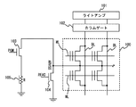
従来の半導体装置の構成を図1に示す。複数のメモリセルMCからなるセルアレイ部100は、ワード線WLとビット線BLとの交差位置にメモリセルMCが配置されている。各メモリセルMCのゲートはワード線WLに、ドレイン端子はビット線BLにそれぞれ接続される。図1に示すセルアレイ部100は、データの読み出し、書き込み、消去の単位となる1セクタを示しており、同一セクタ内のメモリセルMCのソース端子は、共通のソース線ARVSSに接続される。
A configuration of a conventional semiconductor device is shown in FIG. In the
メモリセルMCは、フローティングゲートに電荷がチャージされないデータ「1」の状態と、電荷がチャージされたデータ「0」の状態とを保持している。データ「1」ではしきい値電圧が低く、データ「0」ではしきい値電圧が高くなる。 The memory cell MC holds a state of data “1” in which no charge is charged in the floating gate and a state of data “0” in which the charge is charged. The threshold voltage is low for data “1” and the threshold voltage is high for data “0”.
データの読み出し時には、ワード線WLに所定の電圧を印加し、図1に示すn型MOSトランジスタ(以下、nMOSトランジスタと表記する)104をオンにしてソース線ARVSSをグランド電圧にする。これにより2つの状態でのドレイン電流の違いから、記憶データが読み出される。またデータの書き込み時には、書き込み対象の選択メモリセルMCが接続されたビット線BLに6V程度の高い電圧を、ワード線WLに10V程度の高い電圧を印加し、セルに電流を流すことで生じるホットエレクトロンをフローティングゲートに注入する。非選択のワード線WLには0Vを印加し、非選択メモリセルが導通しないようにする。 When reading data, a predetermined voltage is applied to the word line WL, the n-type MOS transistor (hereinafter referred to as nMOS transistor) 104 shown in FIG. 1 is turned on, and the source line ARVSS is set to the ground voltage. As a result, the stored data is read out from the difference in drain current between the two states. When data is written, a high voltage of about 6 V is applied to the bit line BL to which the selected memory cell MC to be written is connected, a high voltage of about 10 V is applied to the word line WL, and a hot current generated by flowing a current through the cell. Electrons are injected into the floating gate. 0 V is applied to the non-selected word line WL so that the non-selected memory cell is not turned on.
しかしながら、非選択メモリセルMCのワード線が0Vに制御されても、非選択メモリセルMCがオンしてしまう場合がある。選択されたメモリセルのビット線BLには高い電圧が印加されているため、このビット線BLに接続している選択メモリセルと非選択メモリセルとのドレイン線のカップリング作用により、非選択メモリセルMCのフローティングゲートの電圧が上昇し、非選択メモリセルMCがオンしてしまう。それに伴い、ビット線BLに非選択メモリセルMCからのリーク電流が発生し、ビット線BLの寄生抵抗による電圧低下で選択メモリセルMCのドレイン電圧が低下し、ソース・ドレイン電圧が不十分になり、プログラム動作に不具合を生じる。 However, even if the word line of the unselected memory cell MC is controlled to 0V, the unselected memory cell MC may be turned on. Since a high voltage is applied to the bit line BL of the selected memory cell, the non-selected memory is coupled by the coupling action of the drain line between the selected memory cell and the non-selected memory cell connected to the bit line BL. The voltage of the floating gate of the cell MC rises and the unselected memory cell MC is turned on. As a result, a leakage current from the unselected memory cell MC is generated in the bit line BL, the drain voltage of the selected memory cell MC is lowered due to a voltage drop due to the parasitic resistance of the bit line BL, and the source / drain voltage becomes insufficient. This causes problems in program operation.
このような書き込み動作の不具合を防止するため、書き込み時のソース線ARVSSの電圧をグランド電圧よりも若干高い電圧に制御する方法がとられている。すなわち、書き込み時には図1に示すプログラム信号(PGM)によりnMOSトランジスタ103をオンさせて、ソース線ARVSSとグランドの間に設けた抵抗105に書き込み電流を流すことで、ソース線ARVSSの電圧をグランド電圧Vssより若干高くし、書き込み動作でない時にはnMOSトランジスタ104をオンさせてソース線の電圧をグランド電圧Vssに制御する。
In order to prevent such a problem in the writing operation, a method is employed in which the voltage of the source line ARVSS at the time of writing is controlled to a voltage slightly higher than the ground voltage. That is, at the time of writing, the
特許文献1では、選択したセルトランジスタと、ビット線を高電圧にするプログラム電圧発生回路との間の距離に応じて、選択セルトランジスタのソース電圧を変更している。
In
近年の半導体装置は大容量化が図られ、セルアレイ領域が大きくなってきている。セルアレイ領域が大きくなると、ビット線の抵抗やソース線の抵抗が無視できないほど大きくなる。またメモリセルへの書き込み時間の短縮も図られるようになってきており、書き込みパルスのパルス幅はできるだけ小さく設定される。 In recent years, the capacity of semiconductor devices has been increased, and the cell array region has become larger. As the cell array region becomes larger, the resistance of the bit line and the resistance of the source line become so large that they cannot be ignored. In addition, the time for writing to the memory cell has been shortened, and the pulse width of the write pulse is set as small as possible.
このため、大きな負荷があるソース線を短時間でチャージしようとしても、ソース線の電圧が充分とはならず、リーク電流が発生して書き込み効率を低下させるという問題がある。特許文献1にもこのような技術課題は開示されていない。
Therefore, even if an attempt is made to charge a source line with a large load in a short time, there is a problem that the voltage of the source line is not sufficient, and a leakage current is generated to reduce the writing efficiency.
また、ソース線とグランドの間に抵抗を設けることで書き込み中にソース線をバイアスする方法では、書き込むセルの位置によってグラントまでの電圧降下の程度が異なったり、書き込み中の電流値も一定ではないため、ソース線の電圧を一定のレベルに正確に制御することは困難である。 Also, in the method of biasing the source line during writing by providing a resistor between the source line and the ground, the degree of voltage drop to the grant differs depending on the position of the cell to be written, and the current value during writing is not constant. For this reason, it is difficult to accurately control the voltage of the source line to a certain level.
本発明は上記事情に鑑みてなされたものであり、データの書き込み時間が短縮されてもメモリセルへのデータ書き込みを最適に行う半導体装置およびソース電圧制御方法を提供することを目的とする。 The present invention has been made in view of the above circumstances, and an object of the present invention is to provide a semiconductor device and a source voltage control method that optimally write data to a memory cell even when the data write time is shortened.
かかる目的を達成するために本発明の半導体装置は、メモリセルと、前記メモリセルのソース線をデータの書き込み前に電源に接続し前記ソース線を所定電圧とし、データの書き込み時には前記電源から遮断するプリチャージ回路と、データの書き込み時に前記ソース線をグランドと接続し前記ソース線の電圧を所定値以下となるように制御するクランプ回路と、を有して構成している。 In order to achieve such an object, the semiconductor device of the present invention connects a memory cell and a source line of the memory cell to a power source before writing data, sets the source line to a predetermined voltage, and shuts off the power source when writing data And a clamp circuit for controlling the source line voltage to be a predetermined value or less by connecting the source line to the ground when writing data .
メモリセルのソース線をデータの書き込み前にプリチャージしておくことで、データの書き込み時間が短縮されてもメモリセルのソース電圧が低下することがない。従って、データの書き込み時のリーク電流の発生を防止し、メモリセルへのデータ書き込みを最適に行うことができる。 By precharging the source line of the memory cell before writing data, the source voltage of the memory cell does not decrease even if the data writing time is shortened. Therefore, it is possible to prevent the occurrence of leakage current during data writing and optimally write data to the memory cell.
上記の半導体装置において、前記プリチャージ回路は、前記メモリセルのゲート電圧の昇圧中に前記ソース線を所定電圧にする回路を含む構成とすることができる。 In the semiconductor device described above, the precharge circuit may include a circuit that sets the source line to a predetermined voltage while boosting the gate voltage of the memory cell.
メモリセルのゲート電圧の昇圧中にソース線のプリチャージを行うことで、データの書き込み前にソース線を充分な電圧にプリチャージすることができる。 By precharging the source line while boosting the gate voltage of the memory cell, the source line can be precharged to a sufficient voltage before data is written.
上記の半導体装置において、前記プリチャージ回路は、複数のセクタのソース線に選択的に接続される共通ソース線の電圧と基準電圧とを比較して、該共通ソース線の電圧が一定となるように前記共通ソース線を所定電圧にする回路を含む構成とすることができる。 In the semiconductor device, the precharge circuit compares a voltage of a common source line selectively connected to source lines of a plurality of sectors with a reference voltage so that the voltage of the common source line becomes constant. The circuit may include a circuit for setting the common source line to a predetermined voltage .
プリチャージ回路によってプリチャージされる共通ソース線を、選択されたセクタのソース線に接続することでセクタのソース線を所望の電圧にプリチャージすることができる。またプリチャージ回路は、共通ソース線の電圧を基準電圧と比較しながら共通ソース線をチャージすることで、共通ソース線の電圧を一定となるように制御することができる。 By connecting the common source line precharged by the precharge circuit to the source line of the selected sector, the source line of the sector can be precharged to a desired voltage. The precharge circuit can control the voltage of the common source line to be constant by charging the common source line while comparing the voltage of the common source line with the reference voltage.
上記の半導体装置は、前記メモリセルの前記ソース線を前記電源に接続する配線と、前記メモリセルの前記ソース線と前記プリチャージ回路とを接続し前記配線とは別の配線と、を有している。また、前記プリチャージ回路は、前記別の配線の電圧と基準電圧とを比較して、前記ソース線の電圧が一定となるように制御する回路を含む構成とすることができる。 The semiconductor device includes a wiring that connects the source line of the memory cell to the power supply, and a wiring that connects the source line of the memory cell and the precharge circuit and is different from the wiring. ing. The precharge circuit may include a circuit that compares the voltage of the other wiring with a reference voltage and controls the source line voltage to be constant.
メモリセルのソース線と前記プリチャージ回路とを接続する配線の電圧と基準電圧とを比較することで、メモリセルのソース線を所望の電圧に正確に設定することができる。 By comparing the voltage of the wiring connecting the source line of the memory cell and the precharge circuit with the reference voltage, the source line of the memory cell can be accurately set to a desired voltage.
上記半導体装置において、前記クランプ回路は、前記メモリセルのドレインに高電圧を印加している期間だけ前記ソース線の電圧が前記所定値以下となるように制御する回路を含む構成とすることができる。 In the semiconductor device, the clamp circuit may include a circuit that controls the source line voltage to be equal to or lower than the predetermined value only during a period in which a high voltage is applied to the drain of the memory cell. .
メモリセルのドレインに高電圧を印加している期間だけソース線の電圧が一定値以上にならないように制御しているので、必要な期間だけクランプ回路を動作させることができる。 Since the voltage of the source line is controlled so as not to exceed a certain value only during a period when a high voltage is applied to the drain of the memory cell, the clamp circuit can be operated only during a necessary period.
上記の半導体装置において、前記クランプ回路は、複数のセクタのソース線が選択的に接続される共通ソース線の電圧と基準電圧とを比較して、該共通ソース線の電圧が一定値となるように制御する回路を含む構成とすることができる。 In the above semiconductor device, the clamp circuit compares the voltage of the common source line to which the source lines of a plurality of sectors are selectively connected with a reference voltage so that the voltage of the common source line becomes a constant value. It is possible to adopt a configuration including a circuit to be controlled.
共通ソース線の電圧と基準電圧とを比較して、共通ソース線の電圧が一定値となるように制御することで、共通ソース線の電圧を一定値に保つことができる。 By comparing the voltage of the common source line with the reference voltage and controlling the voltage of the common source line to be a constant value, the voltage of the common source line can be maintained at a constant value.
上記の半導体装置において、前記メモリセルの前記ソース線を前記グランドに接続する配線と、前記メモリセルの前記ソース線と前記クランプ回路とを接続し前記配線とは別の配線と、を具備し、前記クランプ回路は、前記別の配線の電圧と基準電圧とを比較して、前記ソース線の電圧が一定となるように制御する回路を含む構成とすることができる。 In the semiconductor device described above, a wiring that connects the source line of the memory cell to the ground, and a wiring that connects the source line of the memory cell and the clamp circuit and is different from the wiring, The clamp circuit may include a circuit that compares the voltage of the another wiring with a reference voltage and controls the source line voltage to be constant.
メモリセルのソース線とプリチャージ回路とを接続する配線の電圧と基準電圧とを比較することで、メモリセルのソース線の電圧を所望の値に正確に設定することができる。 By comparing the voltage of the wiring connecting the source line of the memory cell and the precharge circuit with the reference voltage, the voltage of the source line of the memory cell can be accurately set to a desired value.
本発明の半導体装置は、前記プリチャージ回路は、前記メモリセルのドレインに高電圧が印加される前に、前記メモリセルのソース線を前記所定電圧にする構成としている。 In the semiconductor device of the present invention, the precharge circuit is configured such that the source line of the memory cell is set to the predetermined voltage before a high voltage is applied to the drain of the memory cell .
上記の半導体装置において、データの書き込み時には、選択された前記メモリセルのソース線を、抵抗を介してグランドに接続するとよい。 In the above semiconductor device, the source line of the selected memory cell may be connected to the ground through a resistor when data is written.
データの書き込み時に、選択されたメモリセルのソース線を抵抗を介してグランドに接続し、ソース線と抵抗に書き込み電流を流すことでソース線をバイアスすることができる。 When writing data, the source line of the selected memory cell is connected to the ground via a resistor, and the source line can be biased by flowing a write current through the source line and the resistor.
上記の半導体装置において、前記メモリセルは、電荷を蓄える層として、多結晶シリコンからなるフローティンゲートを用いたメモリセルであるとよい。 In the above-described semiconductor device, the memory cell may be a memory cell using a floating gate made of polycrystalline silicon as a charge storage layer.
多結晶シリコンからなるフローティングゲートを用いたメモリセルの場合、非選択メモリセルのフローティングゲートの電圧がカップリングで上がり、リーク電流が発生するという問題を生じるが、請求項1から9のいずれかに記載の半導体装置とすることで、データ書き込み時のリーク電流の発生を防止することができる。
If the memory cell using a floating gate of polycrystalline silicon, up in voltage coupling of the floating gates of the unselected memory cell, but there arises a problem that leakage current is generated, to any one of
本発明のソース電圧制御方法は、メモリセルのソース線をデータの書き込み前に電源に接続し前記ソース線を所定電圧とするステップと、データの書き込み時に前記ソース線を前記電源から遮断するステップと、前記メモリセルへのデータの書き込み時に、前記ソース線をグランドと接続し前記ソース線の電圧が所定値以下となるように制御するステップと、を有している。 The source voltage control method of the present invention includes a step of connecting a source line of a memory cell to a power supply before writing data and setting the source line to a predetermined voltage, and a step of cutting off the source line from the power supply during data writing And, when writing data to the memory cell, connecting the source line to the ground and controlling the voltage of the source line to be a predetermined value or less .
メモリセルのソース線をデータの書き込み前にプリチャージしておくことで、データの書き込み時間が短縮されてもメモリセルのソース電圧が低下するのを防止することができる。従って、データの書き込み時のリーク電流の発生を防止し、メモリセルへのデータの書き込みを最適化することができる。 By precharging the source line of the memory cell before writing data, it is possible to prevent the source voltage of the memory cell from being lowered even if the data writing time is shortened. Therefore, it is possible to prevent the occurrence of leakage current during data writing and to optimize data writing to the memory cell.
上記の前記プリチャージする工程は、前記メモリセルのゲート電圧の昇圧中に前記ソース線をプリチャージする工程であるとよい。 The step of precharging may be a step of precharging the source line during boosting of the gate voltage of the memory cell.
メモリセルのゲート電圧の昇圧中にソース線の電圧のプリチャージを行うことで、データの書き込み前にソース線を充分な電圧にプリチャージすることができる。 By precharging the source line voltage while boosting the gate voltage of the memory cell, the source line can be precharged to a sufficient voltage before data is written.
上記の前記ソース線の電圧を制御する工程は、前記メモリセルのドレインに高電圧を印加している間だけ前記ソース線の電圧が前記所定値以下となるように制御するとよい。 The step of controlling the voltage of the source line may be controlled so that the voltage of the source line is not more than the predetermined value only while a high voltage is applied to the drain of the memory cell.
メモリセルのドレインに高電圧を印加している期間だけソース線の電圧が一定値以上にならないように制御しているので、必要な期間だけクランプ回路を動作させることができる。 Since the voltage of the source line is controlled so as not to exceed a certain value only during a period when a high voltage is applied to the drain of the memory cell, the clamp circuit can be operated only during a necessary period.
本発明は、データの書き込み時間が短縮されてもデータの書き込み時にメモリセルのソース電圧が低下するのを防止することができる。従って、データの書き込み時のリーク電流の発生を防止し、メモリセルへのデータ書き込みを最適に行うことができる。 The present invention can prevent the source voltage of a memory cell from being lowered during data writing even when the data writing time is shortened. Therefore, it is possible to prevent the occurrence of leakage current during data writing and optimally write data to the memory cell.
次に添付図面を参照しながら本発明の最良の実施例を説明する。 Next, preferred embodiments of the present invention will be described with reference to the accompanying drawings.
まず、図2を参照しながら本実施例の半導体装置の構成を説明する。図2に示す半導体装置1は、制御回路2、高電圧生成回路3、ロウデコーダ4、スイッチング回路5、ソース電源6、ソースデコーダ7、カラムデコーダ8、カラムゲート9、セルアレイ部10、リファレンス回路11、センスアンプ(比較回路)12、出力バッファ13、入力バッファ14、ライトアンプ15、書込回路16などを備えている。この半導体装置1は単独でパッケージされたフラッシュメモリ等の半導体記憶装置であってもよいし、システムLSIのように半導体装置の一部として組み込まれたものであってもよい。
First, the configuration of the semiconductor device of this embodiment will be described with reference to FIG. A
セルアレイ部10は、ワード線WLに接続されたコントロールゲートと、ビット線BLに接続されたドレインと、ソース線ARVSSに接続されたソースと、電荷を蓄える層として、多結晶シリコンからなるフローティングゲートとを含む不揮発性のメモリセルMCを有し、このメモリセルMCが複数個マトリックス状に配置されている。
The
制御回路2は、ライトイネーブル(/WE)等の制御信号や、アドレス信号、データ信号を外部から受け取り、これらの信号に基づいてステートマシンとして動作し、メモリセルMCに対して書き込み、消去および読み出し等の動作を行うために各々の内部回路を制御する。
The
高電圧生成回路3は、電源電圧Vccを所定のレベルになるように調整することで、ビット線電圧、ワード線電圧を生成して書込回路16に供給する。ロウデコーダ4は、不図示のアドレスバッファから供給されたアドレスをデコードする。スイッチング回路5は、メモリセルのワード線WLをデコード結果に応じて活性化させる。ソースデコーダ7は、ソース電源6から電源の供給を受け、ソース線ARVSSを選択する。カラムデコーダ8は、不図示のアドレスバッファから供給されたアドレスをデコードする。
The high
カラムゲート9は、デコードアドレス信号に基づいて、読み出し時にはセルアレイ部10のビット線BLを選択的にセンスアンプ12に接続する。また書き込み時にはビット線BLを選択的にライトアンプ15に接続する。これによって、セルアレイ部10のメモリセルMCに対するデータの読み出し/書き込み経路が確立される。
The
リファレンス回路11は、ゲート電圧が印加されるリファレンスセル(トランジスタ)と、リファレンスセルのリファレンスレベルをシフトさせる回路部とを含む。このリファレンスセルは、リード用のリファレンスセル、プログラム用のリファレンスセル、イレース用のリファレンスセルおよびコンバージェンス用のリファレンスセル等のように各種のリファレンスセルに用いられる。 The reference circuit 11 includes a reference cell (transistor) to which a gate voltage is applied, and a circuit unit that shifts the reference level of the reference cell. This reference cell is used for various reference cells such as a read reference cell, a program reference cell, an erase reference cell, and a convergence reference cell.
センスアンプ12は、メモリセルMCのデータをリファレンスセルのデータと比較することで、メモリセルMCのデータが0であるのか1であるのかを判定し、判定結果を読み出しデータとして出力バッファ13へ供給する。 The sense amplifier 12 compares the data in the memory cell MC with the data in the reference cell to determine whether the data in the memory cell MC is 0 or 1, and supplies the determination result to the output buffer 13 as read data. To do.
書込回路16は、制御回路2の制御の下に、ロウデコーダ4、カラムデコーダ8を駆動して、メモリセルMCに対するデータ書き込み動作を実行する。
The write circuit 16 drives the
プログラム動作およびイレース動作に伴うベリファイ動作は、ロウデコーダ4およびカラムデコーダ8によって指定されたメモリセルMCから供給されたデータの電流を、プログラムベリファイ用リファレンスセルおよびイレースベリファイ用リファレンスセルの示すリファレンス電流と比較することで行われる。
The verify operation associated with the program operation and the erase operation is performed by using the current of the data supplied from the memory cell MC designated by the
また、外部から入力したデータは、一旦入力バッファ14に蓄積され、カラムデコーダ8により選択されたビット線BLにライトアンプ15によりデータを書き込むことで、選択されたメモリセルMCにデータが書き込まれる。
Further, data input from the outside is temporarily accumulated in the input buffer 14, and the data is written to the selected memory cell MC by writing the data to the bit line BL selected by the
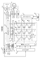
次に、メモリセルMCのソース線ARVSSの電圧を調整する機能部について図3を参照しながら説明する。まず、セルアレイ部10の構成を説明する。図3に示すようにセルアレイ部10は、複数のブロック(図3には、ブロック1〜ブロックNを示す)からなり、各ブロック内には読み出し、書き込み及び消去の単位となるセクタが複数設けられている。本実施例では、1ブロック内には8つのセクタ(セクタ0〜セクタ7)が設けられている。各セクタ内にはそれぞれ所定個のメモリセルMCが配置されている。
Next, a functional unit for adjusting the voltage of the source line ARVSS of the memory cell MC will be described with reference to FIG. First, the configuration of the
同一セクタ内の複数のメモリセルMCは、共通のソース線ARVSSに接続されている。例えば図3に示すセクタ3(1)内のメモリセルMCは、すべてソース線ARVSS3(1)に接続しており、セクタ2(N)のメモリセルMCは、すべてソース線ARVSS2(N)に接続している。なお、セクタ3(1)は、ブロック1に含まれる3番目のセクタであることを示している。
A plurality of memory cells MC in the same sector are connected to a common source line ARVSS. For example, all the memory cells MC in the sector 3 (1) shown in FIG. 3 are connected to the source line ARVSS3 (1), and all the memory cells MC in the sector 2 (N) are connected to the source line ARVSS2 (N). is doing. Note that sector 3 (1) is the third sector included in
各ソース線ARVSSには、ソース線ARVSSの活性、非活性を切り換えるnMOSトランジスタ50がそれぞれ設けられている。このnMOSトランジスタ50のゲートには、ソースデコーダ7からのプログラム信号PGMが入力される。例えば、セクタ3(1)のソース線の活性、非活性を切り換えるnMOSトランジスタ50には、ソースデコーダ7からプログラム信号PGM3(1)が入力される。このプログラム信号PGMによってnMOSトランジスタ50がオンすると、該当するセクタのメモリセルMCのソース線ARVSSが配線55を介して共通ソース線ARVSSR60に接続される。データ読み出し時には、この共通ソース線ARVSSR60が接地電圧Vssとなり(不図示)、データ書き込み時にはソース電源6によって所定電圧に設定される(本実施例では0.6V)。共通ソース線ARVSSRに抵抗40を接続して、この共通ソース線ARVSSRにソース電源6から電流を流し、また書き込み電流をこの抵抗40に流すことで共通ソース線ARVSSRが所定電圧に設定される。共通ソース線ARVSSR60は、各セクタ(メモリセルMC)のソースが共通に接続される配線であり、この共通ソース線ARVSSR60には、図3に示すプリチャージ回路20と、クランプ回路30とが接続されている。
Each source line ARVSS is provided with an
プリチャージ回路20は、図3に示すように差動増幅回路21と、p型MOSトランジスタ(以下、pMOSトランジスタと表記する)22とを備えている。差動増幅回路21には、この差動増幅回路21の動作を制御するPGMSTART信号(制御信号)を入力する。また差動増幅回路21は、基準電圧Vrefと共通ソース線ARVSSR60の電圧との論理によって、pMOSトランジスタ22のゲートに信号を出力する。pMOSトランジスタ22は、ゲートを差動増幅回路21の出力に接続し、ドレインを共通ソース線ARVSSR60に接続し、ソースをソース電源6からの電源電圧Vccに接続している。
As shown in FIG. 3, the
PGMSTART信号(制御信号)は、書き込み要求があってメモリセルMCのゲート電圧を昇圧している期間にハイレベルとなり、その後メモリセルMCのドレインに高電圧を印加している期間は、ローレベルとなる。pMOSトランジスタ22のゲートをコントロールする差動増幅回路21は、PGMSTART信号(制御信号)がハイレベルとなると動作を開始し、共通ソース線ARVSSRの電圧が基準電圧Vrefを超えるまで(共通ソース線ARVSSR60の電圧が一定値に達するまで)pMOSトランジスタ22をオンさせ、共通ソース線ARVSSRをプリチャージする。差動増幅回路21は、それ以外の期間ではハイレベルを出力してpMOSトランジスタ22をオフさせる。
The PGMSTART signal (control signal) is at a high level during a period when there is a write request and the gate voltage of the memory cell MC is boosted, and after that a high voltage is applied to the drain of the memory cell MC. Become. The
クランプ回路30は、図3に示すように共通ソース線ARVSSR60とグランドの間に設けられる抵抗40に並列に設けられ、差動増幅回路31と、インバータ32と、nMOSトランジスタ33とを備えている。差動増幅回路31には、制御信号であるPGMSTART信号(制御信号)の出力をインバータ32で反転させた信号が入力される。また、差動増幅回路31は、基準電圧Vrefと共通ソース線ARVSSR60の電圧との論理によって、nMOSトランジスタ33のゲートに信号を出力する。nMOSトランジスタ33は、ゲートを差動増幅回路31の出力に接続し、ドレインを共通ソース線ARVSSR60に接続し、ソースを接地している。
As shown in FIG. 3, the
nMOSトランジスタ33のゲートをコントロールする差動増幅回路31は、PGMSTART信号(制御信号)がローレベルの期間(差動増幅回路31の入力は、インバータ32で反転してハイレベルとなる)に共通ソース線ARVSSR60の電圧が一定値以上になると、nMOSトランジスタ33をオンさせてクランプを行う。すなわち、共通ソース線ARVSSR60の電圧が所定値以下となるように動作する。差動増幅回路31は、それ以外の期間ではローレベルを出力し、nMOSトランジスタ33をオフさせる。
The
メモリセルMCのソース線ARVSSと、抵抗40との間に存在するnMOSトランジスタ50のスイッチは、動作電源電圧が低く、共通ソース線ARVSSR60の電圧が高く成り過ぎると、十分にオンしないという問題がある。nMOSトランジスタ50のスイッチが十分にオンしないとメモリセルMCへの書き込み効率が低下するという問題が発生する。そこで、クランプ回路30によって共通ソース線ARVSSR60の電圧が所定値以下となるように電圧を固定することで、メモリセルMCへの書き込み効率の低下を防止することができる。
The switch of the
図4に上述した各配線の電圧レベルと、電圧レベルの変化するタイミングとを示す。データの書き込み動作が開始されると、選択されたセクタのnMOSトランジスタ50をオンさせるPGMS(n)が電源電圧Vccに設定される。これと同時に、図3に示すプリチャージ回路20、クランプ回路30に入力されるPGMSTART信号(制御信号)がハイレベルに遷移する。PGMSTART信号(制御信号)は、メモリセルMCのゲート電圧を昇圧している期間(図4に示すワード線WLを昇圧している期間)にハイレベルとなり、その後ドレインに高電圧を印加する実際のプログラム期間(図4に示すビット線BLに高電圧を印加する期間)はローレベルとなる。
FIG. 4 shows the voltage level of each wiring described above and the timing at which the voltage level changes. When the data write operation is started, PGMS (n) for turning on the
プリチャージ回路20は、PGMSTART信号(制御信号)がハイレベルになると動作を開始して、共通ソース線ARVSSR60の電圧を所定の電圧にプリチャージする。共通ソース線ARVSSR60を予めプリチャージしておくことで、実際のプログラム時(ビット線に高電圧を印加する時)にはソース線ARVSSに所望の電圧が印加されているため、データ書き込み時にドレインからのリーク電流の発生を防止することができる。
The
また、クランプ回路30は、PGMSTART信号(制御信号)がハイレベルからローレベルに遷移すると動作を開始し、書き込み電流が流れて共通ソース線ARVSSR60が一定値以上となるとnMOSトランジスタ33をオンさせクランプを行う。すなわち、共通ソース線ARVSSR60の電圧が一定となるように制御を行う。クランプ回路30によって共通ソース線ARVSSRの電圧が所定値以下となるように固定することで、メモリセルMCへの書き込み効率の低下を防止することができる。
The
図4のように、ソース線ARVSSの電圧は、0.5Vから0.7V程度のほぼ一定値に保つことができる。プリチャージ回路20及びクランプ回路30内の差動増幅回路21及び31は、グランドに接続された共通ソース線ARVSSR60をモニタしている。この電圧は0.5Vの一定値に制御されるが、ソース線ARVSSは、各セクタから共通ソース線ARVSSR60までの配線長の相違に起因する電圧降下により、セクタの位置によってその電圧に多少のばらつきがある。例えば、図3に示すセクタ0(1)を選択した場合には、共通ソース線ARVSSR60からセクタのソースARVSS0(1)までの配線長は、図3に示すABであるが、セクタ3(1)を選択した場合には、配線長はACとなる。従って、選択したセクタによって、そのソース線ARVSSから共通ソース線ARVSSR60までの電圧降下がそれぞれ異なり、ソース線ARVSSの電圧が0.5V〜0.7Vで変動することになる。
As shown in FIG. 4, the voltage of the source line ARVSS can be maintained at a substantially constant value of about 0.5V to 0.7V. The
尚、抵抗40は、書き込み中にIRドロップを生じさせて共通ソース線ARVSSR60をある程度高い電圧に設定するが、この抵抗40は用いずに、プリチャージ回路20とクランプ回路30だけでソース電圧を制御するようにしても良い。
The
次に、本発明の第2実施例について説明する。本実施例の構成を図5に示す。本実施例は、プリチャージ回路20、クランプ回路30で基準電圧Vrefと電圧を比較するノードを共通ソース線ARVSSR60ではなく、メモリセルからグランドへのパスがない配線(ARVSSC)を設けて、その配線上の電圧を基準電圧Vrefと比較する。この実施例によれば、第1の実施例で生じたソース線ARVSS電圧のセクタによるばらつきをなくすことができる。
Next, a second embodiment of the present invention will be described. The configuration of this embodiment is shown in FIG. In this embodiment, the node for comparing the voltage with the reference voltage Vref by the
本実施例は図5に示すように、セクタごとに設けられているソース線ARVSSに接続する配線ARVSSC61を設けている。それを介してメモリセルからグランドに電流が流れるパスはない。配線ARVSSC61は、各ソース線ARVSSにスイッチとしてのnMOSトランジスタ51を介して接続している。nMOSトランジスタ51のゲートには、ソースデコーダ7からのプログラム信号PGMが入力されている。セクタが選択され、ソース線ARVSSが共通ソース線ARVSSR60に接続されると、nMOSトランジスタ51もオンして、該当するセクタのソース線ARVSSに配線ARVSSC61を接続する。プリチャージ回路20、クランプ回路30は、選択されたセクタのソース線ARVSSに繋がった配線ARVSSC61上の電圧と基準電圧Vrefとを直接比較して、配線ARVSSC61の電圧、つまりソース線ARVSSを一定の電圧0.6Vに保つように制御する。ソース線ARVSSは、グランドへのパスがない配線(ARVSSC61)を介して電圧が制御されるため、その電圧はセクタの位置によらず一定となる。尚、共通ソース線ARVSSR60の電圧は、0.4Vから0.6Vの間をとるが、これは第1に実施例と同様に、各セクタのソース線ARVSSから共通ソース線ARVSSR60までの間の配線長がセクタ位置に依存するため、選択セクタによってグラントまでの間に生じる電圧降下が異なるためである。このようにして、プリチャージ回路20、クランプ回路30は、メモリセルMCのソース線ARVSSの電圧を正確にプリチャージ、クランプすることができる。
In the present embodiment, as shown in FIG. 5, a
なお、上述した実施例は本発明の好適な実施例である。但し、これに限定されるものではなく、本発明の要旨を逸脱しない範囲内において種々変形実施可能である。例えば、上述した実施例では、プリチャージ回路20とクランプ回路30とを組にして両方設けているが、プリチャージ回路20とクランプ回路30のいずれか一方だけを設けた構成であってもよい。
The above-described embodiment is a preferred embodiment of the present invention. However, the present invention is not limited to this, and various modifications can be made without departing from the scope of the present invention. For example, in the above-described embodiment, both the
Claims (5)
前記メモリセルのソース線をデータの書き込み前に電源に接続し前記ソース線を所定電圧とし、データの書き込み時には前記電源から遮断するプリチャージ回路と、
データの書き込み時に前記ソース線をグランドと接続し前記ソース線の電圧を所定値以下となるように制御するクランプ回路と、
前記メモリセルの前記ソース線を前記電源に接続する配線と、
前記メモリセルの前記ソース線を前記プリチャージ回路または前記クランプ回路に接続する、前記配線とは別の配線と、を具備し、
前記別の配線は、前記メモリセルの前記ソース線とグランドとの間にパスを有さず、
前記プリチャージ回路は、前記データの書き込み前において、前記別の配線の電圧と基準電圧とを比較して、前記ソース線の電圧が一定となるように制御する回路を含み、
前記クランプ回路は、前記別の配線の電圧と基準電圧とを比較して、前記ソース線の電圧が一定となるように制御する回路を含む、半導体装置。A memory cell;
A precharge circuit that connects a source line of the memory cell to a power supply before writing data, sets the source line to a predetermined voltage, and shuts off the power supply when writing data;
A clamp circuit that connects the source line to the ground when writing data and controls the voltage of the source line to be a predetermined value or less ;
Wiring for connecting the source line of the memory cell to the power source;
A wiring different from the wiring for connecting the source line of the memory cell to the precharge circuit or the clamp circuit, and
The another wiring does not have a path between the source line of the memory cell and the ground,
The precharge circuit includes a circuit that controls a voltage of the source line to be constant by comparing a voltage of the other wiring with a reference voltage before writing the data.
The said clamp circuit is a semiconductor device containing the circuit which compares the voltage of said another wiring, and a reference voltage, and controls it so that the voltage of the said source line may become fixed .
Applications Claiming Priority (1)
| Application Number | Priority Date | Filing Date | Title |
|---|---|---|---|
| PCT/JP2004/008998 WO2006001058A1 (en) | 2004-06-25 | 2004-06-25 | Semiconductor device and source voltage control method |
Publications (2)
| Publication Number | Publication Date |
|---|---|
| JPWO2006001058A1 JPWO2006001058A1 (en) | 2008-07-31 |
| JP4680195B2 true JP4680195B2 (en) | 2011-05-11 |
Family
ID=35781610
Family Applications (1)
| Application Number | Title | Priority Date | Filing Date |
|---|---|---|---|
| JP2006527594A Active JP4680195B2 (en) | 2004-06-25 | 2004-06-25 | Semiconductor device and source voltage control method |
Country Status (3)
| Country | Link |
|---|---|
| US (1) | US7206232B2 (en) |
| JP (1) | JP4680195B2 (en) |
| WO (1) | WO2006001058A1 (en) |
Families Citing this family (8)
| Publication number | Priority date | Publication date | Assignee | Title |
|---|---|---|---|---|
| KR100688545B1 (en) * | 2005-05-04 | 2007-03-02 | 삼성전자주식회사 | Erase discharge method of memory device |
| US7420851B2 (en) * | 2006-10-24 | 2008-09-02 | San Disk 3D Llc | Memory device for controlling current during programming of memory cells |
| US7420850B2 (en) * | 2006-10-24 | 2008-09-02 | Sandisk 3D Llc | Method for controlling current during programming of memory cells |
| US7626882B2 (en) * | 2006-12-20 | 2009-12-01 | Spansion Llc | Flash memory device with external high voltage supply |
| US7916544B2 (en) | 2008-01-25 | 2011-03-29 | Micron Technology, Inc. | Random telegraph signal noise reduction scheme for semiconductor memories |
| JP2010211899A (en) * | 2009-03-12 | 2010-09-24 | Toshiba Corp | Semiconductor memory device |
| JP6433871B2 (en) * | 2015-09-10 | 2018-12-05 | 東芝メモリ株式会社 | Semiconductor memory device |
| US9401213B1 (en) * | 2015-11-15 | 2016-07-26 | Winbond Electronics Corp. | Non-volatile memory apparatus and operation method thereof |
Citations (6)
| Publication number | Priority date | Publication date | Assignee | Title |
|---|---|---|---|---|
| JPS57205895A (en) * | 1981-06-12 | 1982-12-17 | Toshiba Corp | Nonvolatile semiconductor memory |
| JPS5977700A (en) * | 1982-10-25 | 1984-05-04 | Toshiba Corp | Non-volatile semiconductor memory device |
| JPH05205895A (en) * | 1991-09-27 | 1993-08-13 | Raytheon Co | Continuous monitoring system of static- electricity discharge system |
| JPH1145587A (en) * | 1997-07-25 | 1999-02-16 | Mitsubishi Electric Corp | Semiconductor integrated circuit device and its programming method |
| WO2001013377A1 (en) * | 1999-08-13 | 2001-02-22 | Advanced Micro Devices, Inc. | Circuit implementation to quench bit line leakage current in programming and over-erase correction modes in flash eeprom |
| JP2003123493A (en) * | 2001-10-12 | 2003-04-25 | Fujitsu Ltd | Nonvolatile memory in which program operation is optimized by controlling source potential |
Family Cites Families (12)
| Publication number | Priority date | Publication date | Assignee | Title |
|---|---|---|---|---|
| US4542485A (en) * | 1981-01-14 | 1985-09-17 | Tokyo Shibaura Denki Kabushiki Kaisha | Semiconductor integrated circuit |
| JPH0528778A (en) * | 1991-07-25 | 1993-02-05 | Toshiba Corp | Nonvolatile semiconductor memory |
| US5590076A (en) * | 1995-06-21 | 1996-12-31 | Advanced Micro Devices, Inc. | Channel hot-carrier page write |
| WO1998048318A1 (en) * | 1997-04-22 | 1998-10-29 | Matsushita Electric Industrial Co., Ltd. | Drive circuit for active matrix liquid crystal display |
| US6108238A (en) * | 1997-09-11 | 2000-08-22 | Kabushiki Kaisha Toshiba | Programmable semiconductor memory device having program voltages and verify voltages |
| KR100295150B1 (en) * | 1997-12-31 | 2001-07-12 | 윤종용 | Method for operating non-volatile memory device and apparatus and method for performing the same |
| DE69913337T2 (en) * | 1999-07-26 | 2004-10-07 | St Microelectronics Srl | Method for programming EEPROM memory arrangements with improved reliability, and corresponding EEPROM memory arrangement |
| JP3606799B2 (en) * | 2000-10-05 | 2005-01-05 | 沖電気工業株式会社 | Semiconductor memory device |
| US6643174B2 (en) * | 2001-12-20 | 2003-11-04 | Winbond Electronics Corporation | EEPROM cells and array with reduced write disturbance |
| US6977842B2 (en) * | 2003-09-16 | 2005-12-20 | Micron Technology, Inc. | Boosted substrate/tub programming for flash memories |
| KR100559714B1 (en) * | 2004-04-19 | 2006-03-10 | 주식회사 하이닉스반도체 | NAND flash memory device and method of programming the same |
| US7457156B2 (en) * | 2004-09-02 | 2008-11-25 | Micron Technology, Inc. | NAND flash depletion cell structure |
-
2004
- 2004-06-25 JP JP2006527594A patent/JP4680195B2/en active Active
- 2004-06-25 WO PCT/JP2004/008998 patent/WO2006001058A1/en active Application Filing
-
2005
- 2005-06-23 US US11/165,008 patent/US7206232B2/en active Active
Patent Citations (6)
| Publication number | Priority date | Publication date | Assignee | Title |
|---|---|---|---|---|
| JPS57205895A (en) * | 1981-06-12 | 1982-12-17 | Toshiba Corp | Nonvolatile semiconductor memory |
| JPS5977700A (en) * | 1982-10-25 | 1984-05-04 | Toshiba Corp | Non-volatile semiconductor memory device |
| JPH05205895A (en) * | 1991-09-27 | 1993-08-13 | Raytheon Co | Continuous monitoring system of static- electricity discharge system |
| JPH1145587A (en) * | 1997-07-25 | 1999-02-16 | Mitsubishi Electric Corp | Semiconductor integrated circuit device and its programming method |
| WO2001013377A1 (en) * | 1999-08-13 | 2001-02-22 | Advanced Micro Devices, Inc. | Circuit implementation to quench bit line leakage current in programming and over-erase correction modes in flash eeprom |
| JP2003123493A (en) * | 2001-10-12 | 2003-04-25 | Fujitsu Ltd | Nonvolatile memory in which program operation is optimized by controlling source potential |
Also Published As
| Publication number | Publication date |
|---|---|
| US7206232B2 (en) | 2007-04-17 |
| US20050286328A1 (en) | 2005-12-29 |
| JPWO2006001058A1 (en) | 2008-07-31 |
| WO2006001058A1 (en) | 2006-01-05 |
Similar Documents
| Publication | Publication Date | Title |
|---|---|---|
| EP0713222B1 (en) | An integrated circuit memory device | |
| EP0713164B1 (en) | A reference circuit | |
| KR0184093B1 (en) | Non-volatile semiconductor memory device and data erasing method therefor | |
| JP2001057088A (en) | Nand type non-volatile memory | |
| KR100423894B1 (en) | Low-voltage semiconductor memory device | |
| JPH10241382A (en) | Semiconductor integrated circuit | |
| JP2002251896A (en) | Non-volatile memory having bit line setup circuit and discharge circuit for programming, and its programming method | |
| KR19980047428A (en) | Flash non-volatile semiconductor memory device and method of controlling the operation mode of the device | |
| JPH11306783A (en) | Boost circuit and semiconductor memory device | |
| US6735120B2 (en) | Semiconductor device having a high-speed data read operation | |
| JP3702229B2 (en) | Semiconductor memory device | |
| US7206232B2 (en) | Semiconductor device and source voltage control method | |
| JP2000276882A (en) | Non-volatile semiconductor memory and erasing method for its storage data | |
| JP3709606B2 (en) | Nonvolatile semiconductor memory device and verify method | |
| JP3615009B2 (en) | Semiconductor memory device | |
| US6999345B1 (en) | Method of sense and program verify without a reference cell for non-volatile semiconductor memory | |
| JP2004355675A (en) | Nonvolatile semiconductor memory device and its control method | |
| US7796441B2 (en) | Method of reading configuration data in flash memory device | |
| JP2005285223A (en) | Nonvolatile semiconductor storage device and its data rewriting method | |
| US7616486B2 (en) | Cell array of semiconductor memory device and method of driving the same | |
| JP2001014877A (en) | Voltage generating circuit and semiconductor storage provided with it | |
| JP4960078B2 (en) | Nonvolatile semiconductor memory device | |
| KR20040021773A (en) | Flash memory reducing peak current | |
| JP3181478B2 (en) | Nonvolatile semiconductor memory device | |
| JP2888181B2 (en) | Nonvolatile semiconductor memory device |
Legal Events
| Date | Code | Title | Description |
|---|---|---|---|
| A131 | Notification of reasons for refusal |
Free format text: JAPANESE INTERMEDIATE CODE: A131 Effective date: 20100112 |
|
| RD04 | Notification of resignation of power of attorney |
Free format text: JAPANESE INTERMEDIATE CODE: A7424 Effective date: 20100204 |
|
| RD03 | Notification of appointment of power of attorney |
Free format text: JAPANESE INTERMEDIATE CODE: A7423 Effective date: 20100616 |
|
| RD03 | Notification of appointment of power of attorney |
Free format text: JAPANESE INTERMEDIATE CODE: A7423 Effective date: 20100805 |
|
| A02 | Decision of refusal |
Free format text: JAPANESE INTERMEDIATE CODE: A02 Effective date: 20100810 |
|
| A711 | Notification of change in applicant |
Free format text: JAPANESE INTERMEDIATE CODE: A711 Effective date: 20100922 |
|
| A521 | Request for written amendment filed |
Free format text: JAPANESE INTERMEDIATE CODE: A523 Effective date: 20101202 |
|
| A911 | Transfer to examiner for re-examination before appeal (zenchi) |
Free format text: JAPANESE INTERMEDIATE CODE: A911 Effective date: 20101209 |
|
| TRDD | Decision of grant or rejection written | ||
| A01 | Written decision to grant a patent or to grant a registration (utility model) |
Free format text: JAPANESE INTERMEDIATE CODE: A01 Effective date: 20110125 |
|
| A01 | Written decision to grant a patent or to grant a registration (utility model) |
Free format text: JAPANESE INTERMEDIATE CODE: A01 |
|
| A61 | First payment of annual fees (during grant procedure) |
Free format text: JAPANESE INTERMEDIATE CODE: A61 Effective date: 20110202 |
|
| R150 | Certificate of patent or registration of utility model |
Ref document number: 4680195 Country of ref document: JP Free format text: JAPANESE INTERMEDIATE CODE: R150 Free format text: JAPANESE INTERMEDIATE CODE: R150 |
|
| FPAY | Renewal fee payment (event date is renewal date of database) |
Free format text: PAYMENT UNTIL: 20140210 Year of fee payment: 3 |
|
| FPAY | Renewal fee payment (event date is renewal date of database) |
Free format text: PAYMENT UNTIL: 20140210 Year of fee payment: 3 |
|
| RD02 | Notification of acceptance of power of attorney |
Free format text: JAPANESE INTERMEDIATE CODE: R3D02 |
|
| R250 | Receipt of annual fees |
Free format text: JAPANESE INTERMEDIATE CODE: R250 |
|
| R250 | Receipt of annual fees |
Free format text: JAPANESE INTERMEDIATE CODE: R250 |
|
| S111 | Request for change of ownership or part of ownership |
Free format text: JAPANESE INTERMEDIATE CODE: R313111 |
|
| R350 | Written notification of registration of transfer |
Free format text: JAPANESE INTERMEDIATE CODE: R350 |
|
| R250 | Receipt of annual fees |
Free format text: JAPANESE INTERMEDIATE CODE: R250 |
|
| R250 | Receipt of annual fees |
Free format text: JAPANESE INTERMEDIATE CODE: R250 |
|
| R250 | Receipt of annual fees |
Free format text: JAPANESE INTERMEDIATE CODE: R250 |
|
| R250 | Receipt of annual fees |
Free format text: JAPANESE INTERMEDIATE CODE: R250 |
|
| R250 | Receipt of annual fees |
Free format text: JAPANESE INTERMEDIATE CODE: R250 |
|
| R250 | Receipt of annual fees |
Free format text: JAPANESE INTERMEDIATE CODE: R250 |
|
| R250 | Receipt of annual fees |
Free format text: JAPANESE INTERMEDIATE CODE: R250 |
|
| S111 | Request for change of ownership or part of ownership |
Free format text: JAPANESE INTERMEDIATE CODE: R313113 |
|
| R350 | Written notification of registration of transfer |
Free format text: JAPANESE INTERMEDIATE CODE: R350 |
|
| R250 | Receipt of annual fees |
Free format text: JAPANESE INTERMEDIATE CODE: R250 |