JP4679710B2 - Noise suppression processing apparatus and recording medium - Google Patents
Noise suppression processing apparatus and recording medium Download PDFInfo
- Publication number
- JP4679710B2 JP4679710B2 JP2000324904A JP2000324904A JP4679710B2 JP 4679710 B2 JP4679710 B2 JP 4679710B2 JP 2000324904 A JP2000324904 A JP 2000324904A JP 2000324904 A JP2000324904 A JP 2000324904A JP 4679710 B2 JP4679710 B2 JP 4679710B2
- Authority
- JP
- Japan
- Prior art keywords
- band
- noise
- image signal
- edge
- smoothing
- Prior art date
- Legal status (The legal status is an assumption and is not a legal conclusion. Google has not performed a legal analysis and makes no representation as to the accuracy of the status listed.)
- Expired - Fee Related
Links
- 238000012545 processing Methods 0.000 title claims description 84
- 230000001629 suppression Effects 0.000 title claims description 63
- 239000013598 vector Substances 0.000 claims description 87
- 238000009499 grossing Methods 0.000 claims description 84
- 238000000034 method Methods 0.000 claims description 62
- 230000005855 radiation Effects 0.000 claims description 53
- 230000008569 process Effects 0.000 claims description 30
- 238000004364 calculation method Methods 0.000 claims description 11
- 230000003247 decreasing effect Effects 0.000 claims 1
- 238000010586 diagram Methods 0.000 description 20
- 238000003384 imaging method Methods 0.000 description 16
- 238000001914 filtration Methods 0.000 description 10
- 230000003044 adaptive effect Effects 0.000 description 7
- 238000000354 decomposition reaction Methods 0.000 description 7
- 230000006866 deterioration Effects 0.000 description 7
- 238000006243 chemical reaction Methods 0.000 description 6
- 230000000694 effects Effects 0.000 description 6
- 238000012935 Averaging Methods 0.000 description 5
- OAICVXFJPJFONN-UHFFFAOYSA-N Phosphorus Chemical compound [P] OAICVXFJPJFONN-UHFFFAOYSA-N 0.000 description 5
- 230000007423 decrease Effects 0.000 description 5
- 238000010606 normalization Methods 0.000 description 5
- 230000001419 dependent effect Effects 0.000 description 4
- 230000002238 attenuated effect Effects 0.000 description 3
- 230000004069 differentiation Effects 0.000 description 3
- 101000920618 Homo sapiens Transcription and mRNA export factor ENY2 Proteins 0.000 description 2
- 102100031954 Transcription and mRNA export factor ENY2 Human genes 0.000 description 2
- 230000008859 change Effects 0.000 description 2
- 238000003745 diagnosis Methods 0.000 description 2
- 238000011156 evaluation Methods 0.000 description 2
- 238000011835 investigation Methods 0.000 description 2
- 238000000926 separation method Methods 0.000 description 2
- NCGICGYLBXGBGN-UHFFFAOYSA-N 3-morpholin-4-yl-1-oxa-3-azonia-2-azanidacyclopent-3-en-5-imine;hydrochloride Chemical compound Cl.[N-]1OC(=N)C=[N+]1N1CCOCC1 NCGICGYLBXGBGN-UHFFFAOYSA-N 0.000 description 1
- 230000002411 adverse Effects 0.000 description 1
- 238000013459 approach Methods 0.000 description 1
- 210000000988 bone and bone Anatomy 0.000 description 1
- 230000015556 catabolic process Effects 0.000 description 1
- 238000006731 degradation reaction Methods 0.000 description 1
- 230000010354 integration Effects 0.000 description 1
- 238000005457 optimization Methods 0.000 description 1
- 238000004321 preservation Methods 0.000 description 1
- 238000002601 radiography Methods 0.000 description 1
- 230000009467 reduction Effects 0.000 description 1
- 238000009877 rendering Methods 0.000 description 1
- 230000035945 sensitivity Effects 0.000 description 1
- 230000009466 transformation Effects 0.000 description 1
Images


Landscapes
- Apparatus For Radiation Diagnosis (AREA)
- Image Processing (AREA)
- Facsimile Image Signal Circuits (AREA)
- Image Analysis (AREA)
Description
【0001】
【発明の属する技術分野】
本発明は、放射線画像を担持する入力画像信号に対して、放射線画像に含まれるノイズ成分を抑制させるノイズ抑制処理を施すノイズ抑制処理装置およびこのノイズ抑制処理をコンピュータに実行させるためのプログラムを記録した記録媒体に関するものである。
【0002】
【従来の技術】
コンピューテッド・ラジオグラフィ装置(以下CR装置という)などを用いて取得した放射線画像を診断に資するに際しては、得られた放射線画像に対して周波数強調処理や階調処理など所望の画像処理を施して診断に適する画像とした後にCRTモニタにソフトコピーとして表示させたり、フィルムにハードコピーとして出力することが行なわれている。
【0003】
ここで、放射線画像は、放射線量が少なく濃度が低い部分において、放射線の量子ノイズが目立ってしまうという問題がある。このため、放射線画像を担持する画像信号中に含まれるノイズ成分を抑制させるノイズ抑制処理を施す方法が種々提案されている。
【0004】
例えば特開平6-96200 号には、画像を一連のデテール像(解像度レベル1〜M段までの帯域制限画像信号)に多重解像度分解し、各デテール像において注目画素近辺(N×N画素分)の領域に対する2乗和(移動平均)を計算し、この2乗和のデテール象に亘るヒストグラムのピークからノイズ分散を算出し、このノイズ分散と各画素に対応する2乗和の値とを比較し、2乗和の値がノイズ分散より小さいときはデテール信号を小さくすることによりデテール像のノイズを抑制し、この後、逆多重解像度変換を行なって画像を復元することにより、ノイズ成分が抑制された画像を得る方法が提案されている。
【0005】
また、上記特開平6-96200 号には、最高解像度レベルの画像(最も密なデテール像)のノイズ分散に基づいてそれよりも低解像度レベルの画像におけるノイズ分散を計算する手法も提案されている。
【0006】
【発明が解決しようとする課題】
しかしながら、上記特開平6-96200号に記載された方法は、ノイズは画像全体において均一であるという考えに従い、該当解像度信号(デテール像)のみの2乗和(移動平均)とそのヒストグラムから算出したノイズ分散値を用いてノイズ抑制を行なっている。しかし実際の放射線画像は、ある画像の中でも例えば直接X線があたっている領域はノイズが少なく例えば被写体が写っている領域ではノイズが多くなるというように、画像全体に亘ってノイズが均一であるということはない。したがって、ヒストグラムから算出した閾値を用いてノイズ抑制を行なうならば、ノイズが少ない領域では、ノイズと一緒にエッジ情報までもが抑制されるためエッジ劣化が生じ鮮鋭度の低下した画像となってしまい、ノイズが多い領域ではノイズが十分に抑制できないという問題がある。
【0007】
また、様々な構造を有する被写体の場合と、多くの横造を有しない被写体とではヒストグラムの形状が異なるものになるから、被写体に応じてノイズとエッジとの分離を最適に行なうことは難しい。
【0008】
本発明は、上記事情に鑑みなされたものであり、線量に拘わらずノイズを効果的に抑制あるいは除去するとともに、ノイズが多い画像に対してノイズ除去処理を施した際に生じ得るエッジ劣化を少なくすることができるノイズ抑制処理装置および該ノイズ抑制処理をコンピュータに実行させるためのプログラムを記録したコンピュータ読取り可能な記録媒体を提供することを目的とするものである。
【0009】
【課題を解決するための手段】
本発明のノイズ抑制処理装置は、入力された放射線画像を担持する入力画像信号に対して平滑化フィルタを用いた平滑化処理を施す平滑化処理手段を具備し、放射線画像に含まれるノイズ成分を抑制させるノイズ抑制処理装置において、放射線画像を得た際の放射線の線量を示す情報(以下線量情報ともいう)に基づいて、入力画像信号のノイズ特性を算出するノイズ特性算出手段を備え、平滑化処理手段が、この算出されたノイズ特性に基づいて、平滑化処理を施すために用いられる平滑化フィルタの特性を切り替えるものであることを特徴とする。
【0010】
放射線画像を得た際の放射線の線量を示す情報は、フォトタイマーからの情報など放射線画像を得た際の放射線の線量を直接的に示すものに限らず、撮影メニュー、患者年齢、撮影条件(撮影装置における放射線照射条件)、規格化条件(特開平2−108175号などを参照)、または画像の信号値(濃度値)など、放射線の線量を間接的に示し得るもの(線量相当のもの)であってもよい。
【0011】
また、本発明のノイズ抑制処理装置においては、入力画像信号に基づいて、それぞれが異なる周波数帯域を有する画像を担持する複数の帯域制限画像信号を作成する帯域制限画像信号作成手段をさらに備えたものとするとともに、平滑化処理手段を、複数の帯域制限画像信号それぞれに対して平滑化フィルタを用いた平滑化処理を施すものとすることが望ましい。
【0012】
この帯域制限画像信号作成手段としては、入力画像信号を多重解像度分解することにより複数の帯域制限画像信号を作成するものとすることが望ましい。この場合、ノイズ抑制処理が施された帯域制限画像信号に対して逆多重解像度展開を施すことにより画像再構成を行なうこととなる。多重解像度分解としては、例えばラプラシアンピラミッド分解やウェーブレット変換などを用いるとよい。
【0013】
「放射線画像を得た際の放射線の線量を示す情報に基づいて」とは、少なくとも前記放射線の線量を示す情報に基づいてという意味であり、この放射線の線量を示す情報に加えて、その他の情報を用いるものであってもよいのはいうまでもない。その他の情報としては、例えば注目画素近傍の局所情報(局所的に計算された情報)を用いることができる。すなわち、本発明のノイズ抑制処理装置においては、ノイズ特性算出手段を、複数の帯域制限画像信号の少なくとも1つについての注目画素近傍の値から局所的に計算された情報にも基づいてノイズ特性を得るものとすることが望ましい。
【0014】
「局所的に計算された情報」としては、エッジらしさを判定し得る情報であればよく、例えばベクトル情報や濃度値の局所平均(移動平均値でもよい)、あるいは局所2乗和などを用いることができる。
【0015】
この場合、ノイズ特性算出手段を、少なくとも1つの帯域制限画像信号により表される帯域制限画像の注目画素における画素ベクトルを求め、この画素ベクトルを前記局所的に計算された情報として用いてノイズ特性としてのエッジ方向を検出するものとし、平滑化処理手段を、この検出されたエッジ方向に沿って平滑化処理を施すように平滑化フィルタの特性を切り替えるものとすることが望ましい。
【0016】
本発明の記録媒体は、入力された放射線画像を担持する入力画像信号に対して、放射線画像に含まれるノイズ成分を抑制させるノイズ抑制処理をコンピュータに実行させるためのプログラムを記録したコンピュータ読取り可能な記録媒体であって、前記プログラムが、放射線画像を得た際の放射線の線量を示す情報に基づいて、入力画像信号のノイズ特性を算出する手順と、この算出されたノイズ特性に基づいて、入力画像信号に対して平滑化処理を施すために用いられる平滑化フィルタの特性を切り替える手順と、この切り替えられた平滑化フィルタを用いて入力画像信号に対して平滑化処理を施す手順をコンピュータに実行させるものであることを特徴とする。
【0017】
本発明の記録媒体は、入力された放射線画像を担持する入力画像信号に対して、放射線画像に含まれるノイズ成分を抑制させるノイズ抑制処理をコンピュータに実行させるためのプログラムを記録したコンピュータ読取り可能な記録媒体であって、前記プログラムが、入力画像信号に基づいて、それぞれが異なる周波数帯域を有する画像を担持する複数の帯域制限画像信号を作成する手順と、放射線画像を得た際の放射線の線量を示す情報に基づいて入力画像信号のノイズ特性を算出する手順と、この算出されたノイズ特性に基づいて複数の帯域制限画像信号それぞれに対して平滑化処理を施すために用いられる平滑化フィルタの特性を切り替える手順と、この切り替えられた平滑化フィルタを用いて複数の帯域制限画像信号それぞれに対して平滑化処理を施す手順をコンピュータに実行させるものとすることもできる。
【0018】
【発明の効果】
本発明のノイズ抑制処理装置および記録媒体によれば、放射線画像を得た際の放射線の線量を示す情報(線量情報)に基づいて入力画像信号のノイズ特性を算出し、この算出されたノイズ特性に基づいて平滑化フィルタの特性を切り替える構成としたので、線量に拘わらずノイズが効果的に抑制・除去された画像を得ることができる。
【0019】
また、帯域制限画像信号を作成して各帯域制限画像信号に対して平滑化フィルタを用いた平滑化処理を施すものとした場合には、ノイズ抑制処理が施された各帯域制限画像信号に基づいて1つの画像信号を再構成すればよく、この場合にも、線量に拘わらずノイズが効果的に抑制・除去された画像を得ることができる。
【0020】
また、複数の帯域制限画像信号の少なくとも1つについての注目画素近傍の値から局所的に計算された情報に基づいてノイズ特性を得るものとすれば、エッジの程度と、線量情報とを加味したノイズ特性が得られ、領域ごとのノイズ変化に対応してエッジとノイズの分離が容易となるため、エッジ劣化が少なく、且つノイズが効果的に抑制された画像が得られる。
【0021】
この場合、特に帯域制限画像の注目画素における画素ベクトルを求め、この画素ベクトルを局所的に計算された情報として用いてノイズ特性としてのエッジ方向を検出し、この検出されたエッジ方向に沿って平滑化処理を施すように平滑化フィルタの特性を切り替える構成とすれば、ノイズが多い画像に対してノイズ抑制を行なった際に生じ得るエッジの劣化を低減し、撮影線量による画質のばらつきを抑制することができる。つまり、エッジ方向に沿って平滑化処理を施すことができるから、エッジ上にのったノイズを適正に抑制することができ、またエッジコントラストを低減することなくエッジ上のノイズを一層効果的に抑制することができるなど、エッジを保存しつつノイズを効果的に抑制することができる。
【0022】
加えて、各特定方向ごとにそれぞれ平滑化の程度が異なる複数のフィルタを予め用意しておき、算出されたノイズ特性に基づいてこの複数のフィルタの中からいずれかを選択することにより平滑化フィルタの特性を切り替える構成とすれば、上記ノイズ抑制処理を高速に行なうことができ、処理全体のスループットを向上させることができる。
【0023】
さらに、入力画像信号を多重解像度分解して各帯域制限画像信号を作成する構成とすれば、帯域制限画像信号の作成処理や画像再構成の処理を高速に行なうことができるから、処理全体のスループットを一層向上させることができる。
【0024】
【発明の実施の形態】
以下、図面を参照して本発明の実施の形態について詳細に説明する。
【0025】
図1は本発明のノイズ抑制処理装置の一実施形態の構成を示す概略ブロック図である。
【0026】
ノイズ抑制処理装置100は、図1に示すように、読取装置などにおいて得られた所定の解像度を有する放射線画像を担持する入力画像信号Sinに基づいて、それぞれが異なる周波数帯域を有する画像を担持する複数の帯域制限画像信号を作成する帯域制限画像信号作成部1と、放射線画像を得た際の放射線の線量を示す情報に基づいて、放射線量に応じたノイズ成分を抑制させる程度を示す指標値を得る指標値取得部2と、この得られた指標値に基づいて複数の帯域制限画像信号のそれぞれについてノイズ抑制処理を施すノイズ抑制処理部3と、それぞれノイズ抑制処理が施された複数の帯域制限画像信号に基づいてノイズが抑制された放射線画像を担持する処理済画像信号Sprocを再構成する画像再構成部4とを有する。
【0027】
指標値取得部2は、本発明のノイズ特性算出手段として機能するように構成されている。すなわち、この指標値取得部2は、帯域制限画像の注目画素における画素ベクトルを求め、この画素ベクトルを用いてノイズ特性としてのエッジ方向を検出するように構成されている。
【0028】
また、ノイズ抑制処理部3は、本発明の平滑化処理手段として機能するように構成されている。すなわち、このノイズ抑制処理部3は、指標値取得部2において算出(検出)されたノイズ特性としてエッジ方向に沿って平滑化処理を施すように平滑化フィルタの特性を切り替え、この特性が切り替えられた平滑化フィルタを用いて帯域制限画像信号Bk のそれぞれについて平滑化処理を施すように構成されている。
【0029】
なお、本実施形態は、例えば特開昭55-12429号や同56-11395号などに記載のように、蓄積性蛍光体シートを利用した放射線画像情報記録再生システムにおいて、蓄積性蛍光体シートに記録された人体の放射線画像をレーザビーム走査によりデジタル画像信号として読み取ったものをノイズ抑制処理の対象としている。放射線画像の読み取りは、蓄積性蛍光体シートに対して主走査方向(横方向)にレーザビームを走査させながらシートを副走査方向(縦方向)に移動させてシートを2次元走査することにより行なわれる。
【0030】
次に上記構成のノイズ抑制処理装置100の作用について説明する。
【0031】
最初に図2に示すフローチャートを参照して、処理の概要について説明する。
【0032】
帯域制限画像信号の作成処理としては、例えば特開平5-244508号、同6-096200号、あるいは特願平 11-363766号および特願 2000-022828号などにおいて本願出願人が提案しているラプラシアンピラミッド分解や、特開平6-274615号や特願平 11-363766号などにおいて本願出願人が提案しているウェーブレット変換などの多重解像度変換の手法を用いるとよい。また、特開平10-75364号などに示されているようにボケマスク信号を用いて取得する方法など、公知のその他の方法を用いてもよい。以下の実施形態では、ラプラシアンピラミッドの手法を用いるものとして説明する。
【0033】
入力された原画像から、多重解像度変換の一態様であるラプラシアンピラミッド分解を用いて帯域制限画像信号を得る(ステップS21)。そして、本発明の評価値としての、帯域制限画像信号が担持する多重解像度空間に分解された各帯域制限画像の各画素位置におけるベクトル成分を算出する(ステップS22)。なお、ベクトル成分は、後述するDouble-Angle表現にて算出すると、ある画素位置において、45度ごとの4方向のベクトルを算出することになる。これら4方向ベクトルから、該当画素位置における情報がノイズ成分なのかエッジ成分なのかを識別することができる。
【0034】
しかしながら、周辺のベクトルに比べて極端に大きなベクトルを持つなどの特異点(局所的なノイズ)が存在すると、その画素位置での局所的なノイズをエッジ信号と間違えるため、1次元フィルタを用いて各ベクトル成分の近傍平均をとることとする(ステップS23)。ベクトル平均は、エッジ信号は連続しているという仮定から成り立っている。本実施形態では、後述するように、等方性の2次元空間フィルタを用いて近傍平均をとる。また、このベクトル平均を、対象解像度より低解像度のベクトル成分を用いて修正する。このとき、原画像を得た際の放射線の線量に応じてベクトル平均を修正する(ステップ24)。
【0035】
次に、平均され且つ修正された各ベクトルに基づいて、後述する方法にしたがって、それぞれノイズ抑制度の一態様であるエッジ信頼性Cと画素エネルギEを算出し(ステップ25)、このエッジ信頼性Cと画素エネルギEを用いて、適応的フィルタリングによるノイズ抑制処理を施す(ステップS26)。そして最後に、逆多重解像度変換の一態様であるラプラシアンピラミッド再構成を行なってノイズが抑制された処理済画像を得る(ステップS27)。
【0036】
ステップS26における適応的フィルタリングは、異方性フィルタ(方向依存フィルタ)と等方性フィルタ(方向に依存しないフィルタ)に分けて行なう。異方性フィルタは、例えば予め数10種類の異方性フィルタ係数を算出しておき、ベクトル方向Dおよびノイズ量に応じて1種類のフィルタ係数を選択するようにする。一方、等方性フィルタは、単純な非線形変換で実現することとする。
【0037】
なお、等方性フィルタの作成に当たっては、マスクの中心におけるフィルタ係数を1とし、その他の係数を下記式(1)により算出することとする。そして、係数の総和が1となるように正規化する。
【数1】

一方、異方性フィルタの作成に当たっては、下記式(2)により算出することとする。そして、係数の総和が1となるように正規化する。
【数2】
次に、各ステップにおいて行なう処理の詳細について説明する。
【0040】
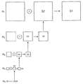
図3は帯域制限画像信号作成部1の概要を示すブロック図、図4は5段階の帯域制限画像信号作成処理を模式的に示す図である。
【0041】
例えば上記特開平5-244508号などに示されているように、フィルタリング処理手段10においては、入力画像信号Sinに対して原画像の主副の各走査方向に対してフィルタリング処理を施して入力画像信号Sinよりも解像度が低い画像信号L1 (以下、低解像度画像信号という)を作成し、次にこの低解像度画像信号L1 に対して同様のフィルタリング処理を施してこの低解像度画像信号L1 よりもさらに解像度が低い低解像度画像信号L2 を作成し、以降順次同様のフィルタリング処理を繰り返して各解像度の低解像度画像信号Lk (k=1〜n)を得る。そして、補間処理手段11において、このフィルタリング処理の各段において得られる低解像度画像信号Lk に対して、主副の各走査方向にそれぞれ2倍(全体としては4倍)の画素数となるように補間処理を施して、鮮鋭度が異なる複数のボケ画像信号Sus1 〜Susn (以下Susk (k=1〜n)で代表させる)を得る。この後、減算器12により互いに対応する画素数を有する低解像度画像信号Lk-1 とボケ画像信号Susk および入力画像信号Sinとボケ画像信号Sus1 との差分を求め、これを帯域制限画像信号Bk とする。
【0042】
次に、上述のようにして求められた帯域制限画像信号Bk を用いてノイズ抑制の程度を示す指標値(ノイズ抑制度)を求め、求めた指標値にしたがってノイズ抑制処理を施す過程について説明する。
【0043】
図5は装置100の全体構成の詳細を示すブロック図である。図示するように、指標値取得部2は、各帯域制限画像信号Bk により表される各帯域制限画像の各画素における画素ベクトル(本発明の評価値の一態様)を得る画素ベクトル取得手段22と、画素ベクトルの長さおよび/または方向に基づいて、エッジ信頼性、画素エネルギ、およびベクトル方向(それぞれ本発明の指標値の一態様)の少なくとも1つを、帯域制限画像信号Bk により表される帯域制限画像の各画素ごとに得る指標値算出手段24とを各帯域制限画像信号Bk ごとに有している。
【0044】
ノイズ抑制処理部3は、指標値算出手段24から出力された指標値に基づいて帯域制限画像信号Bk に含まれるノイズ成分を抑制する処理を施す抑制処理手段32を各帯域制限画像信号Bk ごとに有している。
【0045】
本実施形態のノイズ抑制処理は、「線信号は線方向に平滑化し、孤立ノイズは2次元的に平滑化する」という手法を用いるものである。この処理の最大の特徴は、線信号の平滑化による滑らかなエッジ(線)の描出であり、そのために必要な情報をベクトル形式もしくはテンソル形式のみで表現している点である。本実施形態では、処理に用いる情報として、テンソル形式のものではなく、Double‐Angle表現(以下D−A表現という)という概念のベクトル形式のものを用いる。
【0046】
ベクトルのD−A表現は、線信号を表現するための手法であり、アルゴリズムとしてのメリットは、このD−A表現された情報の近傍平均をとるだけで線信号の信頼性(線らしさの指標)が算出できる点である。この点について、図6を参照して簡単に説明する。
【0047】
図6(A)に示すような画像信号の濃度ベクトルを算出し、通常のベクトル表現(ここではFull-Angle表現;以下F−A表現という)すると同図(B)のようになり、中心の低濃度部領域を境にベクトルの向きが正対する。一方、D−A表現では算出したベクトル角度を2倍するため同図(C)のようになる。
【0048】
これらのベクトルの近傍平均によりエッジ信頼性Cを算出すると、(B),(C)の右側の大矢印のようになり、(C)に対し(B)の信頼性はかなり小さくなる。特に図示していないが、ノイズ(近傍べクトルが様々な方向を向く)も信頼性が小さくなることは容易に想像でき、F−A表現ではノイズと線情報の分離はより困難となる。
【0049】
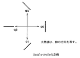
これに対して、D−A表現を用いると、図7に示すように、線方向に対するベクトルを定義することとなる。q0〜q3は、注目画素における各方向成分の大きさを表している。ある画素において、直交する2方向成分の大きさが等しい場合(交点に相当する)、D−A表現では出力が弱くなり、2つの直交する成分の大きさが異なれば、大きい成分を持つ方向が主方向となる。
【0050】
したがって、各画素における4方向成分q0〜q3を算出すれば、ベクトルをD−A表現することができる。
【0051】
以下、各方向成分q0〜q3の具体的な算出方法について具体的に説明する。
【0052】
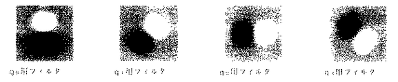
対象となっている帯域制限画像信号は、ラプラシアンピラミッド分解されたラプラシアン信号であり、図8に示す4種類の2次元空間フィルタとのコンボリューションにより4成分を算出する。フィルタ係数の例として5×5のq0フィルタのフィル夕係数を表4−1に示す。ラプラシアン信号とフィルタ係数はどちらも0を中心とした正負の値をとるので、方向成分としてはこれらのコンボリューション積の絶対値を用いる。
【表1】
この4種類のフィルタは何れも一種の微分フィルタなので、ラプラシアン信号のように2次微分された信号に対して施す場合、2次微分信号値が大きくてもその傾きが小さい場所ではフィルタ出力が大きくならない。この様子を図9で説明する。
【0054】
図9は、ラプラシアン信号と1次微分フィルタ出力値(1次微分後の絶対値)との関係を示す図である。図示するように、ラプラシアン信号のA点はエッジ端の一部を表し、ラプラシアン信号は最大値となるが、A点での信号の傾きが0のため、1次微分フィルタによる出力値も0になる。
【0055】
また、エッジと非エッジ境界点であるC点では、信号に傾きがあるためA点での1次微分フィルタ出力値より大きくなる。この傾向は、マスクサイズが大きいほど顕著となる。また、マスクサイズが大きくなると、微小エッジの追従性が悪くなり、微小エッジがボケることも明らかである。
【0056】
したがって、パターン画像のように人工的に生成されたノイズがない画像信号であれば、小マスクサイズが適切である。しかし、実際の自然画像では、程度の差はあるものの画像全体にノイズが加わっているため、小マスクサイズでの1次微分は、ノイズの影響を強く受ける。
【0057】
これらのことは、画素エネルギ(q0〜q3の平均値)を用いた適応的フィルタを施す際、画質に悪影響を与える要因の1つとなる。
【0058】
しかしながら、ノイズの量が推定できれば、ノイズの量に応じてマスクサイズを変更する、あるいはマスクサイズ変更と同等となるフィルタ係数を設定することで、最適化できる可能性がある。本実施形態のように放射線画像を処理対象画像として取り扱う場合、S値(読取感度)やL値(ラチチュード)からX線量とノイズ量を推定し、最適なフィルタ係数を計算することができる。なお、S値やL値に関しては、例えば特開平2−108175号などを参照するとよい。
【0059】
具体的には、各画素に対して算出したベクトル成分(q0〜q3)を、各成分ごとに近傍平均する。近傍平均には、図10に示すような等方性の2次元空間フィルタを用いる。
【0060】
ここで、2次元フィルタのマスクサイズを変えると、当然ベクトル成分の平滑化レベルが変わる。この平滑化レベルは、エッジ信頼性や信号の画素エネルギに反映され、最終画像に与える影響は比較的大きい。マスクサイズを大きくすると、ノイズと比較的大きなエッジ信号は精度良く分離可能となるが、小さなエッジ信号がノイズと見なされる虞れがある。したがって、例えば小児胸部などのように細かな情報がない画像では、大きなマスクサイズでの平滑化が有効である。一方、足画像などの骨画像では、骨梁のような細かな信号が縦横無尽に存在しているため、平滑化レベルを強くすると細かな信号がエッジと認識できないため、小さなマスクサイズを用いることとする。
【0061】
また、このベクトル平均に関しては、本願出願人が特願2000-022828号 において提案したように、対象画像の解像度よりも低解像度画像のベクトル成分を用いて修正する。ここで、本願発明者らの調査によれば、ベクトル平均時にたった今対象としている帯域制限画像信号(注目帯域制限画像)から算出されたベクトルのほかに、別の(より低解像度の)帯域制限画像信号から算出されたベクトルを利用する際、以下のようなことが分かった。
【0062】
1)ノイズが少ない画像(X線が多く照射された画像)は、S/Nが良いため、たった今注目している帯域制限画像信号だけのベクトル平均を用いた方が、細かな信号に対するベクトルの追従性が向上し、エッジ劣化を防止できる。
2)ノイズが多い画像は、S/Nが悪いため、注目している帯域制限画像信号より算出したベクトル(S/Nが悪い)と低周波帯域情報から算出したベクトル(S/Nが向上している)の平均をとることにより、ノイズに埋もれていない比較的大きな信号に対する追従性が増し、大きなノイズ除去効果が得られる。
つまり、画像中に含まれるノイズ量に応じてノイズ抑制の程度をコントロールすることが、画像品質を向上させる上で重要であるということである。
【0063】
次に、ノイズ抑制の程度をコントロールするに際して必要となるノイズ量を推測する方法について説明する。
【0064】
X線画像などの放射線画像の場合、ノイズは主に透過放射線量の減少によりもたらされるため、透過放射線量が分かれば、おおよそのノイズ量を推測できる。
【0065】
また、周波数帯域が異なるベクトルの平均方法は、注目帯域制限信号でのベクトル平均をA、低周波帯域制限信号のベクトル平均をBとすると、ベクトル平均Cは、次式(3)により計算できる。
【数3】
ここで、xはX線量を表し、f(x)はX線量に依存した関数を表し、隣り合う解像度レベルの帯域制限画像信号間のベクトル平均の加算比率に相当する。
【0067】
ノイズ量を推測する手法としては、1)撮影部位や撮影メニュー、2)規格化条件(EDR条件)としてのS値やL値、3)画像の信号値(濃度値)、4)患者年齢あるいは撮影条件など、X線量を示し得る各種情報を用いることができる。
【0068】
撮影部位や撮影メニューを用いる場合には、例えば低線量用メニューあるいは小児メニューを用意し、そのメニューに応じて、注目する帯城制限画像信号のベクトルと、より低周波の帯域制限画像信号のベクトルとの加算比率を変えることで対応できる。S値やL値を用いる場合には、S値が小さいほど(高X線量)f(x)が大きくなるような関数、例えば次式(4)で示すような関数を用いるとよい。勿論これ以外の関数を用いることもできる。
【数4】
画像の信号値を用いる場合には、蓄積性蛍光体シート面上でのX線量と画像濃度とに相関があり、画像信号値は相対的にはX線量を表すから、加算比率の関数として、例えば次式(5)で示すような関数を用いるとよい。
【数5】
なお、ここでは、0≦f(x)≦1.0としたが、例えば、0.5≦f(x)≦1.0の範囲としてもよい。
【0071】
このように信号値を用いる場合は、ベクトル平均を算出するときに、画素位置の画像信号値を参照し、上記式(5)でX線量を推測し、予め定義された関数により求められる加算比率でベクトル平均を算出することになる。
【0072】
次に、4つのベクトル成分(q0〜q3)を用いて、主ベクトルと副ベクトルのそれぞれ方向と長さを算出する。図7に示すように、各ベクトル成分がD−A表現となるように算出されているため、主ベクトル長V1は、式(6)で算出でき、主ベクトルの単位ベクトル成分(ex1,ey1)は、それぞれ式(7)のように算出できる。
【数6】
また、主ベクトルと直交する副ベクトルの単位ベクトル成分(ex2,ey2)は、D−A表現では、主ベクトルと逆方向となるため、式(8)のようになる。
【数8】
また該当画素での画素エネルギVeは、各成分の平均として式(9)で定義できるため、副ベクトル長V2は、画素エネルギVeと主ベクトル長V1の割合から式(10)のように算出できる。
【数9】
次に、平均され且つノイズ量に応じて修正された互いに直交する2つのベクトル情報V1,V2を用いて、それぞれノイズ抑制度の一態様であるエッジ信頼性Cと画素エネルギE、並びに異方性フィルタの平滑化方向Dを以下の式に基づいて決定する。すなわち、画素エネルギEはある閾値Thに対して式(11)で算出し、エッジの信頼性Cは主ベクトル長V1と副ベクトル長V2とから式(12)で算出する。
【数11】
ただし、0.0≦E≦1.0、0.0≦C≦1.0、0≦D≦31(Dは整数)である。
【0077】
また、式(13)に示すように、副ベクトルの単位ベクトル成分から角度θを算出し、算出した角度からさらに規格化された平滑化方向Dを算出する。なお、本実施形態では、全32方向とした。
【数13】
エッジ信頼性Cは、エッジらしさを表す指標であり、該当画素位置が直線上であるほど大きな値をとる一方、画素エネルギEが大きいほど信号であることを示す。エッジ信頼性Cと画素エネルギEとの関係における、直線信号と交点・端点信号およびノイズの認識モデル(適応フィルタの一例)を図11に示す。
【0079】
次に、互いに直交する2つのベクトル情報から算出された画素エネルギE、エッジ信頼性C、および平滑化方向Dに基づいて、各帯域制限画像信号(ラプラシアン信号)の各画素に対して異方性フィルタを用いた平滑化処理と適応的フィルタリングを用いてノイズ抑制処理を施す。
【0080】
ここで、エッジ信頼性Cが大きいほど直線であるため、本実施形態では、先ず直線方向に沿うように異方性フィルタを用いた平滑化処理を施す。換言すれば、ラプラシアン信号に施す異方性の2次元空間フィルタ(方向依存性フィルタ)は、主ベクトル方向に平滑化を行なうものである。この異方性フィルタは、図12に示すような形状をなすように係数が設定されている。このような異方性フィルタを用いる意図は、ノイズが多い画像になると、エッジ信号上にもノイズが重畳するため、エッジコントラストを低減することなくエッジ上のノイズを除去するためである。
【0081】
ここで、図12に示す各異方性フィルタは、黒ほどフィルタ係数が大きいことを示している。また、左側に示した(a)は上下方向に沿った平滑化を実施するためのフィルタであり、中心角θの角度が大きいほど平滑化能力が高いがエッジ信号も平滑化する。さらに、上段に示したものほどマスクサイズが大きいため平滑化能力が高いがエッジ劣化が懸念される一方、下段は逆にマスクサイズが小さく平滑化能力が小さいがエッジ保存の効果がある。
【0082】
このような2次元の異方性フィルタを用いることにより、ベクトル方向に沿った平滑化処理、すなわちエッジを保存しながらエッジ上のノイズを抑制もしくは除去することが可能となるが、本願発明者らの調査によれば、画像上のノイズ量の大小に応じてフィルタが影響を及ぼす範囲(マスクサイズ)と方向性(中心角)の最適値が以下に示すように異なるということが分かった。つまり、画像中に含まれるノイズ量に応じて異方性フィルタを切り替えることが、エッジを保存しながらエッジ上のノイズを抑制もしくは除去する上で重要であるということである。
1)ノイズが少ない画像(X線が多く照射された画像)は、細かな信号に対するベクトルの追従性を向上するため、影響範囲が小さく且つ中心角が小さなフィルタ特性とするのがよい。
2)ノイズが多い画像に対し、上記1)と同じ条件で処理すると、ベクトル方向を向いたノイズとなりアーチファクトとなるため、より平滑化能力が高いフィルタ特性が必要である。
【0083】
次に、異方性フィルタを切り替える際して必要となるノイズ量を推測する方法について説明する。
【0084】
上述のようにX線画像などの放射線画像の場合、ノイズは主に透過放射線量の減少によりもたらされるため、透過放射線量f(x)が分かれば、おおよそのノイズ量を推測できる。
【0085】
ここで、透過放射線量f(x)を推測する手法としては、1)撮影部位や撮影メニュー、2)規格化条件(EDR条件)としてのS値やL値、3)画像の信号値(濃度値)、4)エッジ信頼性、5)患者年齢あるいは撮影条件など、X線量を示し得る各種情報を用いることができる。
【0086】
撮影部位や撮影メニューを用いる場合には、例えば低線量用メニューあるいは小児メニューを用意し、そのメニューに応じて、予めf(x)を設定しておくとよい。
【0087】
S値やL値を用いる場合には、S値が小さいほど(高X線量)f(x)が大きくなるような関数、例えば次式(14)で示すような関数を用いるとよい。勿論これ以外の関数を用いることもできる。
【数14】
画像の信号値を用いる場合には、蓄積性蛍光体シート面上でのX線量と画像濃度とに相関があり、画像信号値は相対的にはX線量を表すから、透過放射線量f(x)として、下記式(15)に示すような関数を用いるのがよい。
【数15】
これらの式を用いてフィルタ処理を施す際には、該当画素位置における画像信号を参照して透過放射線量f(x)を算出し、f(x)に依存してフィルタ特性を切り替える。これにより、例えば、信号値が小さい場合(低X線量領域)、平滑フィルタの中心角は大きくかつ影響範囲も大きくなり、より平滑重視になる。一方、信号値が大きい(高X線量)領域は、中心角も影響範囲も狭くなり、エッジのボケを抑制できる。
【0090】
エッジ信頼性は、前記したようにベクトル平均後に求められる指標であり、この値が大きいほど非ノイズ信号であることになる。ノイズが多い画像になるとエッジ信頼性が低下するため、この信頼性もノイズ量を推測する指標として考えることができる。ここで、エッジ信頼性が高いほど平滑化フィルタの影響範囲と中心角を狭くし、逆にエッジ信頼性が低いほど広くすることで、ノイズ除去と先鋭化が両立できる。
【0091】
なお、異方性フィルタは、エッジに対してはエッジ保存となるが、エッジ交点では平滑化方向に働く。しかし、実際の画像上に見られる交点は、理想的な交点(線がシャープで線が互いに直交している交点)とは異なり、それ程平滑化されない。
【0092】
次に、ベクトルから算出した平滑化方向D(θ)とノイズ量とに応じて方向依存性フィルタとしての異方性フィルタを選択し、選択されたフィルタでコンボリューション(畳込み積分)を行なって変換画像信号としてのコンボリューション積を得る。このコンボリューション積(異方性フィルタ信号)が後述する式(16)や式(17)に記載されているAである。
【0093】
ノイズ抑制処理部3においては、ノイズ成分を抑制するための適応的フィルタリング処理として、上述のように異方性フィルタとラプラシアン信号のコンボリューション積Aを求め、このコンボリューション積Aとラプラシアン信号との加算比率を画素エネルギEおよびエッジ信頼性Cに基づいて制御することで、各帯域制限画像信号(ラプラシアン信号)の各画素に対応する処理済帯域制限画像信号fBk(k=1〜n)(式ではProc で代表させる)を算出する。処理済帯域制限画像信号Proc はノイズ成分が抑制された信号となる。この処理済帯域制限画像信号Proc の算出時の定義には、下記1,2がある。
【0094】
定義1:図11(b)を直線と定義する場合
図11(b)を直線と定義する場合であり、ノイズ成分が抑制された処理済帯域制限画像信号Proc は次式(16)で計算される。
【数16】
エッジ信頼性Cが高いときは、エッジなので異方性フィルタ出力を選択し(第1項)、信頼性が低いときはさらに画素エネルギEによってオリジナルのラプラシアン信号を減衰し、ノイズと交点を分離する(第2項)。
【0096】
定義2:図11(b)をノイズと定義する場合
図11(b)をノイズと定義する場合であり、ノイズ成分が抑制された処理済帯域制限画像信号Proc は次式(17)で計算される。
【数17】
エッジ信頼性Cが高い場合は、画素エネルギEに依存して異方性フィルタ出力を減衰し、ノイズとエッジを分離する(第1項)。エッジ信頼性Cが低い時も画素エネルギEによってオリジナルのラプラシアン信号を減衰し、ノイズと交点を分離する(第2項)。
【0098】
ここで、定義1の場合、S/Nが良い画像ではノイズ除去効果があるものの、S/Nが悪い画像になると効果がほとんどない。この結果から、S/Nが悪くなるとノイズでも線の信頼性が高くなるということが考察できる。
【0099】
また、定義2の場合は、S/Nが悪い画像ほど、不連続感(突然ノイズやエッジが見える現象:局所的な不連続感)を生じアーチファクトとなる。このアーチファクトを消すためには、画素エネルギ算出時の閾値を高くする必要があるが、閾値が高くなると当然エッジもボケることになる。これは、S/Nが悪い画像の場合は、エッジの画素エネルギとノイズの画素エネルギが拮抗しているためであり、画素エネルギを利用している限り必ず生じる問題である。
【0100】
なお、エッジ信頼性Cは非直線信号(交点や端点および点信号など)でも小さな値を有するため、これらの非直線信号とノイズと分離するために、画素エネルギEを用いて、画素エネルギEがある値以上であれは信号、以下であればノイズというような判断を行なうこともできる。実際には、任意の非線形関数により連続的にノイズらしさを決定する。例えば、ノイズらしさNは、閾値TH、画素エネルギに基づいて、次式(18)で示すような非線形関数で決定することもできる。
【数18】
この場合、エッジ信頼性CとノイズらしさNから、上記式(16)に対応して次式(19)を用いたり、あるいは上記式(17)に対応して次式(20)を用いるとよい。
【数19】
上記式(18)における閾値THは、線量相当量に基づいて決まる値であり、線量相当量として画素値を利用するときには画素位置ごとに値が変化する。また、式(18)で定義される関数は、エネルギが大きくなるにつれて1.0に漸近する関数である。例えば、式(19)は、エネルギEが閾値THに対して十分大きいときにはN=1となり処理済帯域制限画像信号Proc が残るが、エネルギEが閾値THに対して十分小さいときにはN=0となるから処理済帯域制限画像信号Proc =0となる。
【0103】
このようにして、ノイズ抑制処理を各帯域制限画像信号に対して施して処理済帯域制限画像信号Proc を得た後、画像再構成部4において、逆多重解像度変換としてのラプラシアン再構成を行ない、ノイズ成分が抑制された画像を表す処理済画像信号Sprocを得る。
【0104】
画像再構成部4には、図5に示すように、ノイズ抑制処理が施された帯域制限画像信号に対して補間処理を施す補間処理手段43と、帯域制限画像信号と補間処理が施された拡大画像信号とを加算する加算器44とが、解像度レベルの段数に応じて設けられている。
【0105】
図13はラプラシアン再構成を行なう処理を模式的に示す図である。ノイズ成分が抑制された処理済帯域制限画像信号fBk (k=1〜n)が得られたら、処理済帯域制限画像信号fBk のうち、最低解像度の信号fBn が1段階高解像度の処理済帯域制限画像信号fBk-1 と同一画素数となるように、補間処理手段43において上記補間処理手段11と同様の補間処理がなされて拡大画像信号Sn′が得られる。この後、処理済帯域制限画像信号fBk-1 と拡大画像信号Sn′とが加算器44において加算されて、加算画像信号Sn−1が得られる。このような処理をより高解像度となる方向に繰り返し行なって、最高解像度の加算画像信号S1を得る。この最高解像度の加算画像信号S1は、ノイズ成分が抑制された処理済画像信号Sprocとなる。
【0106】
したがって、この処理済画像信号Sprocに基づいて画像出力すれば、画質的には、適応的フィルタなどのパラメータ調整をすることで、「低線量画像を、通常線量画像の高周波成分を少し暈かしたような画像」として得ることができる。つまり、放射線画像を得た際のX線量に依存して、注目する帯域制限画像信号の平均ベクトルと、より低周波の帯域制限画像信号の平均ベクトルとの加算比率を制御しているので、高X線量領域では微細エッジ重視のノイズ抑制処理がなされる一方、低X線領域では大きなエッジを重視したノイズ抑制処理がなされるから、総合的には、ノイズを効果的に抑制あるいは除去するとともに、ノイズが多い画像に対してノイズ抑制を行なった際に生じ得るエッジの劣化を軽減し、撮影線量による画質のばらつきを抑制することができる。換言すれば、撮影線量にバラ付きがあるなどに起因して画像に含まれるノイズ成分量が異なる場合においても、常にノイズ抑制効果が大きく、唐草模様状のアーチファクト(不自然さ)を低減させ、より自然な画像を得ることができ、また微細信号の劣化が少ない、高画質な画像を得ることができる。
【0107】
以上本発明のノイズ抑制処理装置の好ましい実施形態について説明したが、本発明は必ずしも上述した実施形態に限定されるものではない。
【0108】
例えば、上記実施形態は、ラプラシアンピラミッドの手法により入力画像信号Sinからそれぞれ異なる周波数帯域を有する帯域制限画像信号を得ているが、例えば特開平6-274615号に示すように、ウェーブレット変換により帯域制限画像信号を得るようにしてもよい。
【0109】
また、ノイズ成分が抑制された各帯域制限画像信号を逆多重解像度変換することによりノイズ成分が抑制された画像を得るようにしていたが、例えば本願出願人が特願平 11-363766号に提案しているように、多重解像度信号を用いてノイズ成分SH1を分離した後、ノイズ分離手段45により入力画像信号Sinからノイズ成分SH1を差し引くことによってノイズ成分が抑制された画像を得るという構成とすることもできる。図14は、このような形態の装置100の詳細を示すブロック図である。
【0110】
また、上記実施形態は、注目画素近傍の値から局所的に算出される情報(以下局所情報という)としてベクトル情報を用い、このベクトル情報に基づいてノイズ抑制度を示す指標値を求めたりフィルタ処理を施すようにしていたが、局所情報は、これに限らず、例えば移動平均値を用いることもできる。移動平均値を用いる場合、一の帯域制限画像信号に対する第1の移動平均値算出時に、撮影メニューやX線撮影条件およびX線相当量などの放射線の線量を示す情報に応じて、より周波数帯域の低い帯域制限画像信号における該当画素における第2の移動平均値を加味するようにしてもよい。
【0111】
さらに、平滑化処理として、等方的な(普通の2次元)空間フィルタのフィルタ係数を切り替えたり、マスクサイズを切り替えたりしてもよい。
【0112】
さらにまた、例えば上記特開平6-96200 号に記載の方法を利用して、詳細画像の局所2乗和とX線量に相当する情報とに基づいて、上記フィルタ特性の切替えを行なうこともできる。ただし、エッジ方向平滑化に比べてエッジ部が劣化しやすくなるため、やはりエッジ方向平滑化の方が好ましい。
【0113】
また、上記実施形態は、それぞれが異なる周波数帯域を有する画像を担持する帯域制限画像信号を作成した後、各帯域制限画像信号それぞれに対して平滑化フィルタを用いた平滑化処理を施すに際して、線量情報に基づいて入力画像信号のノイズ特性を算出し、この算出したノイズ特性に基づいて平滑化フィルタの特性を切り替えるようにしていたが、入力された画像信号そのものに対して平滑化フィルタを用いた平滑化処理を施す場合にも上述同様の手法を適用することができる。また、この場合においても、線量情報に加えて、例えばベクトル情報などの局所情報を用いてノイズ特性を求める手法を同様に適用することもできる。
【0114】
また、上述したノイズ抑制方法をコンピュータにより実行するものとし、該ノイズ抑制方法をコンピュータに実行させるためのプログラムを、コンピュータ読取り可能な記録媒体に記録して提供してもよい。
【図面の簡単な説明】
【図1】本発明のノイズ抑制処理装置の一実施形態の構成を示す概略ブロック図
【図2】本発明のノイズ抑制処理装置における処理手順を示すフローチャート
【図3】帯域制限画像信号作成部の概要を示すブロック図
【図4】帯域制限画像信号作成処理を模式的に示す図
【図5】ノイズ抑制処理装置の全体構成の詳細を示すブロック図
【図6】 Double-Angle表現を説明する概念図
【図7】 Double-Angle表現の定義を説明する図
【図8】4種類の2次元空間フィルタの例を示す図
【図9】ラプラシアン信号と1次微分フィルタ出力値(1次微分後の絶対値)との関係を示す図
【図10】等方性の2次元空間フィルタの例を示す図
【図11】エッジ信頼性と画素エネルギとの関係における、直線信号と交点・端点信号およびノイズの認識モデルを示す図
【図12】異方性フィルタの一例を示す図
【図13】ラプラシアン再構成を行なう処理を模式的に示す図
【図14】本発明のノイズ抑制処理装置の他の実施形態の構成を示す詳細ブロック図
【符号の説明】
100 ノイズ抑制処理装置
1 帯域制限画像信号作成部
2 指標値取得部(ノイズ特性算出手段)
3 ノイズ抑制処理部(平滑化処理手段)
4 画像再構成部[0001]
BACKGROUND OF THE INVENTION
The present invention records a noise suppression processing device that performs noise suppression processing for suppressing noise components included in a radiographic image on an input image signal carrying a radiographic image, and a program for causing a computer to execute the noise suppression processing. It relates to a recording medium.
[0002]
[Prior art]
When a radiographic image acquired using a computed radiography apparatus (hereinafter referred to as a CR apparatus) is used for diagnosis, the obtained radiographic image is subjected to desired image processing such as frequency enhancement processing and gradation processing. Then, after making an image suitable for diagnosis, it is displayed as a soft copy on a CRT monitor or output as a hard copy on a film.
[0003]
Here, the radiation image has a problem that the quantum noise of the radiation becomes conspicuous in a portion where the radiation dose is low and the density is low. For this reason, various methods for performing noise suppression processing for suppressing noise components included in an image signal carrying a radiographic image have been proposed.
[0004]
For example, in Japanese Patent Laid-Open No. 6-96200, an image is subjected to multi-resolution decomposition into a series of detail images (band-limited image signals of
[0005]
Japanese Patent Laid-Open No. 6-96200 also proposes a method for calculating the noise variance in an image at a lower resolution level based on the noise variance of the image at the highest resolution level (the densest detail image). .
[0006]
[Problems to be solved by the invention]
However, the above-mentioned JP-A-6-6 96200 The method described in this issue is based on the idea that noise is uniform throughout the entire image, and noise suppression is performed using the sum of squares (moving average) of the corresponding resolution signal (detail image) and the noise variance calculated from the histogram. Is doing. However, in an actual radiographic image, noise is uniform over the entire image, for example, an area that is directly exposed to X-rays has less noise, for example, an area in which an object is photographed has a greater noise. That's not true. Therefore, if noise suppression is performed using the threshold value calculated from the histogram, in the area where the noise is low, the edge information is suppressed together with the noise, resulting in edge deterioration and an image with reduced sharpness. There is a problem that noise cannot be sufficiently suppressed in a region where there is a lot of noise.
[0007]
In addition, since the shape of the histogram differs between a subject having various structures and a subject that does not have many horizontal structures, it is difficult to optimally separate noise and edges according to the subject.
[0008]
The present invention has been made in view of the above circumstances, and effectively suppresses or removes noise regardless of dose, and reduces edge deterioration that may occur when noise removal processing is performed on an image with much noise. An object of the present invention is to provide a noise suppression processing apparatus capable of performing a noise reduction and a computer-readable recording medium on which a program for causing a computer to execute the noise suppression processing is recorded.
[0009]
[Means for Solving the Problems]
The noise suppression processing apparatus of the present invention includes a smoothing processing unit that performs a smoothing process using a smoothing filter on an input image signal carrying an input radiation image, and removes noise components included in the radiation image. A noise suppression processing apparatus for suppressing, comprising noise characteristic calculation means for calculating noise characteristics of an input image signal based on information indicating radiation dose when a radiation image is obtained (hereinafter also referred to as dose information), and smoothing The processing means switches the characteristics of the smoothing filter used for performing the smoothing process based on the calculated noise characteristics.
[0010]
Information indicating the radiation dose at the time of obtaining the radiation image is not limited to information directly indicating the radiation dose at the time of obtaining the radiation image, such as information from a phototimer. Radiation irradiation conditions in imaging equipment), normalization conditions (see Japanese Patent Laid-Open No. 2-108175, etc.), or image signal values (concentration values) that can indirectly indicate radiation dose (equivalent to dose) It may be.
[0011]
The noise suppression processing apparatus of the present invention further includes band-limited image signal creating means for creating a plurality of band-limited image signals each carrying an image having a different frequency band based on the input image signal. In addition, it is desirable that the smoothing processing means performs a smoothing process using a smoothing filter on each of the plurality of band limited image signals.
[0012]
As the band-limited image signal creating means, it is desirable to create a plurality of band-limited image signals by performing multi-resolution decomposition on the input image signal. In this case, image reconstruction is performed by applying inverse multi-resolution expansion to the band limited image signal that has been subjected to noise suppression processing. As the multiresolution decomposition, for example, a Laplacian pyramid decomposition or wavelet transform may be used.
[0013]
“Based on the information indicating the radiation dose when obtaining the radiation image” means at least based on the information indicating the radiation dose, and in addition to the information indicating the radiation dose, It goes without saying that information may be used. As other information, for example, local information in the vicinity of the target pixel (information calculated locally) can be used. In other words, in the noise suppression processing apparatus of the present invention, the noise characteristic calculation means has the noise characteristic based on information locally calculated from values in the vicinity of the target pixel for at least one of the plurality of band limited image signals. It is desirable to obtain.
[0014]
The “locally calculated information” may be any information that can determine edge-likeness. For example, vector information, a local average of density values (may be a moving average value), or a local square sum is used. Can do.
[0015]
In this case, the noise characteristic calculation means obtains a pixel vector at the target pixel of the band limited image represented by at least one band limited image signal, and uses the pixel vector as the locally calculated information as the noise characteristic. It is preferable that the edge direction is detected, and the smoothing processing means switches the characteristics of the smoothing filter so as to perform the smoothing process along the detected edge direction.
[0016]
The recording medium of the present invention is a computer-readable recording medium storing a program for causing a computer to execute noise suppression processing for suppressing noise components included in a radiographic image with respect to an input image signal carrying an input radiographic image. A recording medium, wherein the program calculates a noise characteristic of an input image signal based on information indicating a radiation dose when a radiographic image is obtained, and an input based on the calculated noise characteristic. The computer executes the procedure for switching the characteristics of the smoothing filter used to smooth the image signal and the procedure for smoothing the input image signal using the switched smoothing filter. It is a thing to let it be.
[0017]
The recording medium of the present invention is a computer-readable recording medium storing a program for causing a computer to execute noise suppression processing for suppressing noise components included in a radiographic image with respect to an input image signal carrying an input radiographic image. A recording medium, wherein the program creates a plurality of band-limited image signals each carrying an image having a different frequency band based on an input image signal, and a radiation dose when the radiation image is obtained The procedure of calculating the noise characteristics of the input image signal based on the information indicating the smoothing filter used to perform the smoothing process on each of the plurality of band limited image signals based on the calculated noise characteristics The procedure for switching the characteristics and each of a plurality of band-limited image signals using the switched smoothing filter It can be assumed to execute a procedure for performing a smoothing process on the computer.
[0018]
【The invention's effect】
According to the noise suppression processing apparatus and the recording medium of the present invention, the noise characteristic of the input image signal is calculated based on information (dose information) indicating the radiation dose when the radiation image is obtained, and the calculated noise characteristic is calculated. Therefore, it is possible to obtain an image in which noise is effectively suppressed / removed regardless of the dose.
[0019]
In addition, when a band-limited image signal is created and a smoothing process using a smoothing filter is performed on each band-limited image signal, the band-limited image signal is subjected to noise suppression processing. In this case, an image in which noise is effectively suppressed / removed can be obtained regardless of the dose.
[0020]
In addition, if noise characteristics are obtained based on information locally calculated from values in the vicinity of a target pixel for at least one of a plurality of band-limited image signals, the degree of edge and dose information are taken into account. Noise characteristics can be obtained, and edge and noise can be easily separated in accordance with noise change for each region. Therefore, an image with little edge deterioration and noise effectively suppressed can be obtained.
[0021]
In this case, in particular, the pixel vector at the target pixel of the band-limited image is obtained, the edge direction as noise characteristics is detected using this pixel vector as locally calculated information, and smoothed along the detected edge direction. If the smoothing filter characteristics are switched so that the image processing is performed, edge deterioration that may occur when noise suppression is performed on a noisy image is reduced, and variations in image quality due to imaging dose are suppressed. be able to. In other words, since the smoothing process can be performed along the edge direction, the noise on the edge can be appropriately suppressed, and the noise on the edge can be more effectively reduced without reducing the edge contrast. Noise can be effectively suppressed while preserving edges, such as being able to suppress.
[0022]
In addition, a plurality of filters having different smoothing levels for each specific direction are prepared in advance, and a smoothing filter is selected by selecting one of the plurality of filters based on the calculated noise characteristics. If the characteristic is switched, the noise suppression process can be performed at high speed, and the throughput of the entire process can be improved.
[0023]
Furthermore, if the input image signal is decomposed into multiple resolutions to create each band-limited image signal, the band-limited image signal creation process and the image reconstruction process can be performed at high speed. Can be further improved.
[0024]
DETAILED DESCRIPTION OF THE INVENTION
Hereinafter, embodiments of the present invention will be described in detail with reference to the drawings.
[0025]
FIG. 1 is a schematic block diagram showing a configuration of an embodiment of a noise suppression processing apparatus of the present invention.
[0026]
As shown in FIG. 1, the noise
[0027]
The index
[0028]
Further, the noise
[0029]
This embodiment is described in, for example, Japanese Patent Laid-Open No. 55-55. 12429 In the radiation image information recording / reproducing system using the stimulable phosphor sheet, the radiographic image of the human body recorded on the stimulable phosphor sheet is converted into a digital image by laser beam scanning. What is read as a signal is the target of noise suppression processing. Reading of the radiation image is performed by moving the sheet in the sub-scanning direction (longitudinal direction) while scanning the laser beam in the main scanning direction (lateral direction) with respect to the stimulable phosphor sheet and scanning the sheet two-dimensionally. It is.
[0030]
Next, the operation of the noise
[0031]
First, an overview of the processing will be described with reference to the flowchart shown in FIG.
[0032]
For example, the Laplacian proposed by the present applicant in Japanese Patent Application Laid-Open No. 5-244508, No. 6-096200, Japanese Patent Application No. 11-363766 and Japanese Patent Application No. 2000-022828, etc. It is preferable to use a method of multiresolution conversion such as pyramid decomposition or wavelet transform proposed by the applicant of the present application in Japanese Patent Application Laid-Open No. 6-27615 and Japanese Patent Application No. 11-363766. Further, other known methods such as a method of obtaining using a blur mask signal as disclosed in JP-A-10-75364 may be used. In the following embodiments, a description will be given assuming that a Laplacian pyramid technique is used.
[0033]
A band-limited image signal is obtained from the input original image using Laplacian pyramid decomposition, which is an aspect of multi-resolution conversion (step S21). Then, a vector component at each pixel position of each band limited image decomposed into the multi-resolution space carried by the band limited image signal as the evaluation value of the present invention is calculated (step S22). When the vector component is calculated by a double-angle expression described later, a vector in four directions every 45 degrees is calculated at a certain pixel position. From these four-direction vectors, it is possible to identify whether the information at the corresponding pixel position is a noise component or an edge component.
[0034]
However, if there is a singular point (local noise) such as having an extremely large vector compared to the surrounding vector, a local noise at the pixel position is mistaken for an edge signal. The neighborhood average of each vector component is taken (step S23). Vector averaging consists of the assumption that edge signals are continuous. In this embodiment, as will be described later, a neighborhood average is obtained using an isotropic two-dimensional spatial filter. Further, the vector average is corrected using a vector component having a resolution lower than the target resolution. At this time, the vector average is corrected according to the radiation dose when the original image is obtained (step 24).
[0035]
Next, based on the averaged and corrected vectors, edge reliability C and pixel energy E, which are one aspect of the noise suppression degree, are calculated according to a method described later (step 25). Noise suppression processing by adaptive filtering is performed using C and pixel energy E (step S26). Finally, Laplacian pyramid reconstruction, which is an aspect of inverse multiresolution conversion, is performed to obtain a processed image in which noise is suppressed (step S27).
[0036]
The adaptive filtering in step S26 is performed separately for an anisotropic filter (direction-dependent filter) and an isotropic filter (direction-independent filter). For the anisotropic filter, for example, several tens of types of anisotropic filter coefficients are calculated in advance, and one type of filter coefficient is selected according to the vector direction D and the amount of noise. On the other hand, the isotropic filter is realized by a simple nonlinear transformation.
[0037]
In creating the isotropic filter, the filter coefficient at the center of the mask is set to 1, and the other coefficients are calculated by the following equation (1). Then, normalization is performed so that the sum of the coefficients becomes 1.
[Expression 1]
On the other hand, when creating the anisotropic filter, it is calculated by the following equation (2). Then, normalization is performed so that the sum of the coefficients becomes 1.
[Expression 2]
Next, details of processing performed in each step will be described.
[0040]
FIG. 3 is a block diagram showing an outline of the band-limited image
[0041]
For example, as disclosed in Japanese Patent Application Laid-Open No. 5-244508, the filtering processing means 10 performs a filtering process on the input image signal Sin in each of the main and sub scanning directions of the original image to obtain an input image. Image signal L with lower resolution than signal Sin 1 (Hereinafter referred to as a low resolution image signal), and then this low resolution image signal L 1 The same filtering process is applied to the low resolution image signal L 1 Low-resolution image signal L whose resolution is even lower than 2 After that, the same filtering process is sequentially repeated, and the low resolution image signal L for each resolution is generated. k (K = 1 to n) is obtained. Then, in the interpolation processing means 11, the low resolution image signal L obtained at each stage of the filtering process. k In contrast, a plurality of blurred image signals Sus1 to Susn (hereinafter referred to as Susk (hereinafter referred to as “Susk”)) are subjected to interpolation processing so that the number of pixels is doubled (4 times as a whole) in each of the main and sub scanning directions. represented by k = 1 to n). Thereafter, the low-resolution image signal L having the number of pixels corresponding to each other by the
[0042]
Next, the band limited image signal B obtained as described above. k A process of obtaining an index value (noise suppression degree) indicating the degree of noise suppression using, and applying noise suppression processing according to the calculated index value will be described.
[0043]
FIG. 5 is a block diagram showing details of the overall configuration of the
[0044]
The noise
[0045]
The noise suppression processing of the present embodiment uses a technique of “smoothing line signals in a line direction and isolated noises two-dimensionally”. The greatest feature of this processing is the rendering of smooth edges (lines) by smoothing the line signal, and the information necessary for this is expressed only in the vector format or the tensor format. In the present embodiment, information used for processing is not a tensor format, but a vector format having a concept of Double-Angle expression (hereinafter referred to as DA expression).
[0046]
The DA expression of a vector is a technique for expressing a line signal, and the merit as an algorithm is that the reliability of the line signal (index of linearity) is obtained simply by taking the neighborhood average of the information expressed in DA. ) Can be calculated. This point will be briefly described with reference to FIG.
[0047]
When a density vector of an image signal as shown in FIG. 6A is calculated and a normal vector expression (here, full-angle expression; hereinafter referred to as FA expression) is obtained, the result is as shown in FIG. The direction of the vector faces the low concentration area. On the other hand, in the D-A expression, the calculated vector angle is doubled as shown in FIG.
[0048]
If the edge reliability C is calculated by the neighborhood average of these vectors, it becomes like a large arrow on the right side of (B) and (C), and the reliability of (B) is considerably smaller than (C). Although not shown in particular, it can be easily imagined that the reliability of noise (neighboring vectors are directed in various directions) is reduced, and separation of noise and line information becomes more difficult in the FA expression.
[0049]
On the other hand, when the DA expression is used, a vector with respect to the line direction is defined as shown in FIG. q0 to q3 represent the size of each direction component in the target pixel. In a pixel, when the orthogonal two-direction components have the same magnitude (corresponding to the intersection), the output is weak in the DA expression, and when the two orthogonal components are different in size, the direction having the larger component is determined. Main direction.
[0050]
Therefore, if the four-direction components q0 to q3 in each pixel are calculated, the vector can be expressed as a DA.
[0051]
Hereinafter, the specific calculation method of each direction component q0-q3 is demonstrated concretely.
[0052]
The target band-limited image signal is a Laplacian signal subjected to Laplacian pyramid decomposition, and four components are calculated by convolution with four types of two-dimensional spatial filters shown in FIG. As an example of the filter coefficient, the filter coefficient of the 5 × 5 q0 filter is shown in Table 4-1. Since both the Laplacian signal and the filter coefficient take positive and negative values centered on 0, the absolute value of these convolution products is used as the direction component.
[Table 1]
Since these four types of filters are all types of differential filters, when applied to a second-order differentiated signal such as a Laplacian signal, the filter output is large at a location where the slope is small even if the second-order differential signal value is large. Don't be. This will be described with reference to FIG.
[0054]
FIG. 9 is a diagram showing the relationship between the Laplacian signal and the first-order differential filter output value (absolute value after the first-order differentiation). As shown in the figure, the point A of the Laplacian signal represents a part of the edge end, and the Laplacian signal has the maximum value, but since the signal slope at the point A is 0, the output value by the primary differential filter is also 0. Become.
[0055]
Further, at point C, which is a boundary point between the edge and the non-edge, the signal has an inclination, which is larger than the output value of the first-order differential filter at point A. This tendency becomes more prominent as the mask size is larger. It is also clear that when the mask size is increased, the followability of the minute edge is deteriorated and the minute edge is blurred.
[0056]
Therefore, a small mask size is appropriate for an image signal having no artificially generated noise such as a pattern image. However, in an actual natural image, noise is added to the entire image although there is a difference in degree. Therefore, the first-order differentiation with a small mask size is strongly influenced by noise.
[0057]
These are one of the factors that adversely affect image quality when an adaptive filter using pixel energy (average value of q0 to q3) is applied.
[0058]
However, if the amount of noise can be estimated, there is a possibility that optimization can be performed by changing the mask size according to the amount of noise or setting a filter coefficient that is equivalent to the mask size change. When a radiographic image is handled as a processing target image as in the present embodiment, an X-ray dose and a noise amount can be estimated from an S value (reading sensitivity) or an L value (latitude), and an optimum filter coefficient can be calculated. Regarding the S value and L value, for example, refer to Japanese Patent Laid-Open No. 2-108175.
[0059]
Specifically, the vector components (q0 to q3) calculated for each pixel are subjected to neighborhood averaging for each component. For the neighborhood average, an isotropic two-dimensional spatial filter as shown in FIG. 10 is used.
[0060]
Here, when the mask size of the two-dimensional filter is changed, the smoothing level of the vector component naturally changes. This smoothing level is reflected in edge reliability and signal pixel energy, and has a relatively large effect on the final image. When the mask size is increased, noise and a relatively large edge signal can be separated with high accuracy, but a small edge signal may be regarded as noise. Therefore, smoothing with a large mask size is effective for an image having no detailed information such as a child's chest. On the other hand, in bone images such as foot images, fine signals such as trabeculae exist in all directions, so if the smoothing level is increased, fine signals cannot be recognized as edges, so use a small mask size. And
[0061]
Further, the vector average is corrected by using a vector component of an image having a resolution lower than the resolution of the target image, as proposed by the present applicant in Japanese Patent Application No. 2000-022828. Here, according to the investigation by the inventors of the present application, in addition to the vector calculated from the band limited image signal (target band limited image) that is the target at the time of vector averaging, another (lower resolution) band limited image is used. When using the vector calculated from the signal, the following was found.
[0062]
1) Since an image with little noise (an image irradiated with a lot of X-rays) has a good S / N, it is better to use a vector average of only the band-limited image signal that is just focused on. Followability is improved and edge deterioration can be prevented.
2) Since an image having a lot of noise has a poor S / N, a vector (S / N is bad) calculated from a focused band-limited image signal and a vector (S / N) calculated from low frequency band information are improved. )), The followability to a relatively large signal that is not buried in noise is increased, and a large noise removal effect can be obtained.
That is, controlling the degree of noise suppression according to the amount of noise included in the image is important for improving the image quality.
[0063]
Next, a method for estimating the amount of noise necessary for controlling the degree of noise suppression will be described.
[0064]
In the case of a radiographic image such as an X-ray image, noise is mainly caused by a decrease in the amount of transmitted radiation. Therefore, if the amount of transmitted radiation is known, an approximate amount of noise can be estimated.
[0065]
Further, the vector averaging method for different frequency bands can be calculated by the following equation (3), where A is the vector average of the target band limited signal and B is the vector average of the low frequency band limited signal.
[Equation 3]
Here, x represents the X-ray dose, f (x) represents a function dependent on the X-ray dose, and corresponds to the vector average addition ratio between the band-limited image signals of adjacent resolution levels.
[0067]
The methods for estimating the amount of noise include 1) imaging region and imaging menu, 2) S value and L value as normalization conditions (EDR conditions), 3) image signal value (concentration value), 4) patient age or Various types of information that can indicate the X-ray dose such as imaging conditions can be used.
[0068]
When using an imaging region or an imaging menu, for example, a low-dose menu or a pediatric menu is prepared, and a vector of a band-limited image signal to be noticed and a vector of a band-limited image signal of a lower frequency depending on the menu. This can be done by changing the addition ratio. When the S value or the L value is used, it is preferable to use a function that increases the (high X-ray dose) f (x) as the S value decreases, for example, a function represented by the following equation (4). Of course, other functions can be used.
[Expression 4]
When using the signal value of the image, there is a correlation between the X-ray dose on the stimulable phosphor sheet surface and the image density, and the image signal value relatively represents the X-ray dose. For example, a function represented by the following equation (5) may be used.
[Equation 5]
Here, although 0 ≦ f (x) ≦ 1.0, the range may be, for example, 0.5 ≦ f (x) ≦ 1.0.
[0071]
When the signal value is used in this way, when calculating the vector average, the image signal value at the pixel position is referred to, the X-ray dose is estimated by the above equation (5), and the addition ratio obtained by a predefined function To calculate the vector average.
[0072]
Next, using the four vector components (q0 to q3), the directions and lengths of the main vector and the subvector are calculated. As shown in FIG. 7, since each vector component is calculated so as to have a DA expression, the main vector length V1 can be calculated by Expression (6), and the unit vector components (ex1, ey1) of the main vector Can be calculated as shown in Equation (7).
[Formula 6]
In addition, the unit vector component (ex2, ey2) of the subvector orthogonal to the main vector is in the opposite direction to the main vector in the DA expression, and thus is expressed by Expression (8).
[Equation 8]
Further, since the pixel energy Ve at the corresponding pixel can be defined by the equation (9) as an average of each component, the sub vector length V2 can be calculated as the equation (10) from the ratio of the pixel energy Ve and the main vector length V1. .
[Equation 9]
Next, using two vector information V1 and V2 that are averaged and corrected according to the amount of noise, the edge reliability C and the pixel energy E, which are one aspect of the noise suppression degree, and the anisotropy, respectively, are used. The smoothing direction D of the filter is determined based on the following formula. That is, the pixel energy E is calculated with respect to a certain threshold Th by the expression (11), and the edge reliability C is calculated by the expression (12) from the main vector length V1 and the subvector length V2.
## EQU11 ##
However, 0.0 ≦ E ≦ 1.0, 0.0 ≦ C ≦ 1.0, and 0 ≦ D ≦ 31 (D is an integer).
[0077]
Further, as shown in Expression (13), the angle θ is calculated from the unit vector component of the subvector, and the normalized smoothing direction D is calculated from the calculated angle. In this embodiment, all 32 directions are used.
[Formula 13]
The edge reliability C is an index representing the likelihood of an edge, and takes a larger value as the pixel position is on a straight line, and indicates that the signal is higher as the pixel energy E is larger. FIG. 11 shows a straight line signal, an intersection / endpoint signal, and a noise recognition model (an example of an adaptive filter) in the relationship between the edge reliability C and the pixel energy E.
[0079]
Next, based on pixel energy E, edge reliability C, and smoothing direction D calculated from two vector information orthogonal to each other, anisotropy is performed for each pixel of each band limited image signal (Laplacian signal). Noise suppression processing is performed using smoothing processing using a filter and adaptive filtering.
[0080]
Here, since the higher the edge reliability C, the straighter the line, in the present embodiment, first, smoothing processing using an anisotropic filter is performed along the linear direction. In other words, the anisotropic two-dimensional spatial filter (direction-dependent filter) applied to the Laplacian signal performs smoothing in the main vector direction. This anisotropic filter has coefficients set so as to have a shape as shown in FIG. The purpose of using such an anisotropic filter is to remove noise on the edge without reducing edge contrast because noise is superimposed on the edge signal when the image has a lot of noise.
[0081]
Here, each anisotropic filter shown in FIG. 12 indicates that the filter coefficient is larger for black. Further, (a) shown on the left side is a filter for performing smoothing along the vertical direction. The larger the center angle θ, the higher the smoothing ability, but the edge signal is also smoothed. Furthermore, as shown in the upper part, since the mask size is larger, the smoothing ability is higher but the edge deterioration is concerned. On the contrary, in the lower part, the mask size is smaller and the smoothing ability is smaller, but there is an effect of edge preservation.
[0082]
By using such a two-dimensional anisotropic filter, smoothing processing along the vector direction, that is, noise on the edge can be suppressed or removed while preserving the edge. According to the above investigation, it was found that the optimum range of the range (mask size) and the directionality (center angle) influenced by the filter differs depending on the amount of noise on the image as shown below. That is, switching the anisotropic filter according to the amount of noise included in the image is important for suppressing or removing noise on the edge while preserving the edge.
1) An image with less noise (an image irradiated with a lot of X-rays) should have a filter characteristic with a small influence range and a small central angle in order to improve vector followability to a fine signal.
2) If an image with a lot of noise is processed under the same conditions as in 1) above, it becomes noise in the vector direction, resulting in artifacts, and therefore a filter characteristic with higher smoothing capability is required.
[0083]
Next, a method for estimating the amount of noise required when switching the anisotropic filter will be described.
[0084]
As described above, in the case of a radiation image such as an X-ray image, noise is mainly caused by a decrease in the amount of transmitted radiation. Therefore, if the amount of transmitted radiation f (x) is known, an approximate amount of noise can be estimated.
[0085]
Here, as methods for estimating the transmitted radiation dose f (x), 1) an imaging region and an imaging menu, 2) an S value and an L value as normalization conditions (EDR conditions), and 3) an image signal value (density) (Value), 4) edge reliability, 5) patient age, imaging conditions, and other information that can indicate the X-ray dose can be used.
[0086]
When using an imaging region or an imaging menu, for example, a low-dose menu or a child menu is prepared, and f (x) is set in advance according to the menu.
[0087]
When using the S value or the L value, it is preferable to use a function that increases the (high X-ray dose) f (x) as the S value decreases, for example, a function represented by the following equation (14). Of course, other functions can be used.
[Expression 14]
When the signal value of the image is used, there is a correlation between the X-ray dose on the stimulable phosphor sheet surface and the image density, and the image signal value relatively represents the X-ray dose. ) Is preferably a function as shown in the following formula (15).
[Expression 15]
When performing filter processing using these equations, the transmitted radiation dose f (x) is calculated with reference to the image signal at the corresponding pixel position, and the filter characteristics are switched depending on f (x). Thereby, for example, when the signal value is small (low X-ray dose region), the center angle of the smoothing filter is large and the influence range is large, and the emphasis is on smoothness. On the other hand, in the region where the signal value is large (high X-ray dose), the central angle and the influence range are narrowed, and blurring of the edge can be suppressed.
[0090]
The edge reliability is an index obtained after vector averaging as described above, and the larger this value is, the non-noise signal is. Since the edge reliability decreases when the image has a lot of noise, this reliability can also be considered as an index for estimating the amount of noise. Here, as the edge reliability is higher, the influence range and the central angle of the smoothing filter are narrowed, and conversely, the lower the edge reliability is, the wider it is, so that both noise removal and sharpening can be achieved.
[0091]
The anisotropic filter is edge-preserving for the edge, but works in the smoothing direction at the edge intersection. However, unlike the ideal intersection (intersection where the line is sharp and the lines are orthogonal to each other), the intersection seen on an actual image is not so smooth.
[0092]
Next, an anisotropic filter as a direction-dependent filter is selected according to the smoothing direction D (θ) calculated from the vector and the amount of noise, and convolution (convolution integration) is performed with the selected filter. A convolution product as a converted image signal is obtained. This convolution product (anisotropic filter signal) is A described in equations (16) and (17) described later.
[0093]
The noise
[0094]
Definition 1: When defining FIG. 11B as a straight line
FIG. 11B is defined as a straight line, and the processed band limited image signal Proc in which the noise component is suppressed is calculated by the following equation (16).
[Expression 16]
When the edge reliability C is high, since it is an edge, the anisotropic filter output is selected (first term). When the reliability is low, the original Laplacian signal is further attenuated by the pixel energy E, and the noise and the intersection are separated. (Section 2).
[0096]
Definition 2: When defining FIG. 11B as noise
FIG. 11B is defined as noise, and the processed band limited image signal Proc in which the noise component is suppressed is calculated by the following equation (17).
[Expression 17]
When the edge reliability C is high, the anisotropic filter output is attenuated depending on the pixel energy E, and the noise and the edge are separated (first term). Even when the edge reliability C is low, the original Laplacian signal is attenuated by the pixel energy E to separate the noise and the intersection (second term).
[0098]
Here, in the case of
[0099]
In the case of
[0100]
Since the edge reliability C has a small value even for non-linear signals (intersection points, end points, point signals, etc.), the pixel energy E is used to separate these non-linear signals and noise. It can also be judged as a signal if it is above a certain value, and as a noise if it is below. Actually, the likelihood of noise is continuously determined by an arbitrary nonlinear function. For example, the noise likelihood N can be determined by a nonlinear function as shown by the following equation (18) based on the threshold value TH and the pixel energy.
[Formula 18]
In this case, from the edge reliability C and the noise likelihood N, the following equation (19) may be used corresponding to the above equation (16), or the following equation (20) may be used corresponding to the above equation (17). .
[Equation 19]
The threshold value TH in the equation (18) is a value determined based on the dose equivalent amount, and the value changes for each pixel position when the pixel value is used as the dose equivalent amount. Further, the function defined by Expression (18) is a function that gradually approaches 1.0 as the energy increases. For example, in the equation (19), when the energy E is sufficiently large with respect to the threshold value TH, N = 1 and the processed band limited image signal Proc remains, but when the energy E is sufficiently small with respect to the threshold value TH, N = 0. Therefore, the processed band limited image signal Proc = 0.
[0103]
Thus, after performing noise suppression processing on each band limited image signal to obtain a processed band limited image signal Proc, the
[0104]
As shown in FIG. 5, the
[0105]
FIG. 13 is a diagram schematically showing processing for performing Laplacian reconstruction. Processed band limited image signal fB with suppressed noise components k When (k = 1 to n) is obtained, the processed band limited image signal fB k Of these, the lowest resolution signal fB n Is a one-step high resolution processed band limited image signal fB k-1 In the
[0106]
Therefore, if an image is output based on the processed image signal Sproc, by adjusting parameters such as an adaptive filter in terms of image quality, “the low-dose image is slightly increased in the high-frequency component of the normal dose image. Image ". In other words, depending on the X-ray dose at the time of obtaining the radiation image, the addition ratio between the average vector of the band-limited image signal of interest and the average vector of the lower-frequency band-limited image signal is controlled. In the X-ray dose region, noise suppression processing is performed with emphasis on fine edges, while in the low X-ray region, noise suppression processing is performed with emphasis on large edges. Therefore, overall, noise is effectively suppressed or removed, Edge degradation that may occur when noise suppression is performed on an image with a lot of noise can be reduced, and variations in image quality due to imaging dose can be suppressed. In other words, even when the amount of noise components included in the image is different due to variations in imaging dose, the noise suppression effect is always great, reducing arabesque pattern artifacts (unnaturalness), A more natural image can be obtained, and a high-quality image with little deterioration of fine signals can be obtained.
[0107]
Although the preferred embodiment of the noise suppression processing apparatus of the present invention has been described above, the present invention is not necessarily limited to the above-described embodiment.
[0108]
For example, in the above-described embodiment, band-limited image signals having different frequency bands are obtained from the input image signal Sin by the Laplacian pyramid technique. For example, as shown in Japanese Patent Application Laid-Open No. 6-274615, band limitation is performed by wavelet transform. An image signal may be obtained.
[0109]
In addition, each band limited image signal in which the noise component is suppressed is obtained by performing inverse multi-resolution conversion to obtain an image in which the noise component is suppressed. For example, the applicant of the present application proposed in Japanese Patent Application No. 11-363766. As shown, after the noise component SH1 is separated using the multi-resolution signal, the
[0110]
In the above embodiment, vector information is used as information locally calculated from values in the vicinity of the target pixel (hereinafter referred to as local information), and an index value indicating a noise suppression degree is obtained based on the vector information, or is subjected to a filtering process. However, the local information is not limited to this, and for example, a moving average value can be used. In the case of using the moving average value, when calculating the first moving average value for one band-limited image signal, the frequency band is more according to information indicating the radiation dose such as the imaging menu, X-ray imaging conditions, and X-ray equivalent amount. The second moving average value of the corresponding pixel in the low band limited image signal may be taken into consideration.
[0111]
Furthermore, as a smoothing process, the filter coefficient of an isotropic (normal two-dimensional) spatial filter may be switched, or the mask size may be switched.
[0112]
Furthermore, the filter characteristics can be switched based on the local sum of squares of the detailed image and information corresponding to the X-ray dose by using, for example, the method described in JP-A-6-96200. However, edge direction smoothing is more preferable than edge direction smoothing, and edge direction smoothing is still preferable.
[0113]
Further, in the above-described embodiment, after creating band-limited image signals that carry images having different frequency bands, doses are applied when performing a smoothing process using a smoothing filter on each of the band-limited image signals. The noise characteristics of the input image signal were calculated based on the information, and the characteristics of the smoothing filter were switched based on the calculated noise characteristics. However, the smoothing filter was used for the input image signal itself. The same technique as described above can also be applied when performing the smoothing process. Also in this case, a technique for obtaining noise characteristics using local information such as vector information in addition to dose information can be similarly applied.
[0114]
Further, the above-described noise suppression method may be executed by a computer, and a program for causing a computer to execute the noise suppression method may be recorded on a computer-readable recording medium and provided.
[Brief description of the drawings]
FIG. 1 is a schematic block diagram showing the configuration of an embodiment of a noise suppression processing apparatus of the present invention.
FIG. 2 is a flowchart showing a processing procedure in the noise suppression processing apparatus of the present invention.
FIG. 3 is a block diagram showing an outline of a band limited image signal creation unit.
FIG. 4 is a diagram schematically illustrating band-limited image signal creation processing.
FIG. 5 is a block diagram showing details of the overall configuration of the noise suppression processing apparatus.
FIG. 6 is a conceptual diagram illustrating Double-Angle expression.
FIG. 7 is a diagram for explaining the definition of Double-Angle expression.
FIG. 8 is a diagram illustrating examples of four types of two-dimensional spatial filters.
FIG. 9 is a diagram showing a relationship between a Laplacian signal and a first-order differential filter output value (absolute value after first-order differentiation).
FIG. 10 is a diagram illustrating an example of an isotropic two-dimensional spatial filter;
FIG. 11 is a diagram showing a recognition model for linear signals, intersection / endpoint signals, and noise in the relationship between edge reliability and pixel energy;
FIG. 12 is a diagram illustrating an example of an anisotropic filter
FIG. 13 is a diagram schematically illustrating processing for performing Laplacian reconstruction.
FIG. 14 is a detailed block diagram showing the configuration of another embodiment of the noise suppression processing apparatus of the present invention;
[Explanation of symbols]
100 Noise suppression processing device
1 Band-limited image signal generator
2 Index value acquisition unit (noise characteristic calculation means)
3 Noise suppression processing unit (smoothing processing means)
4 Image reconstruction unit
Claims (4)
前記平滑化処理を施そうとしている帯域制限画像信号である注目帯域制限画像信号毎にノイズ特性を算出するノイズ特性算出手段であって、前記注目帯域制限画像信号および該注目帯域制限画像信号よりも低い周波数帯の帯域制限画像信号を用いて各注目画素の濃度の勾配を表す主ベクトルおよび該主ベクトルに直交する副ベクトルを算出し、前記主ベクトルおよび前記副ベクトルから各注目画素がエッジ位置に存在する確からしさを示すエッジ信頼性と該エッジのエッジ方向をノイズ特性として算出するノイズ特性算出手段を備え、
該ノイズ特性算出手段が、前記放射線画像を得た際の放射線の線量が多い場合は、前記放射線画像を得た際の放射線の線量が少ないときよりも前記注目帯域制限画像信号の割合を高くし、前記放射線画像を得た際の放射線の線量が少なくなるに従って、前記放射線画像を得た際の放射線の線量が多いときよりも前記低い周波数帯の帯域制限画像信号の割合が高くなるような割合で、前記注目帯域制限画像信号および前記低い周波数帯の帯域制限画像信号を用いて前記主ベクトルおよび前記副ベクトルを算出するものであり、
前記平滑化フィルタが、前記各注目画素において前記エッジ方向に沿って平滑化処理を施すものであり、該平滑化フィルタを、前記エッジ信頼性が高い部分ではエッジのボケを抑制するように前記エッジ方向に沿った平滑化の範囲を狭くし、前記エッジ信頼性が低くなるに従って前記平滑化の範囲を広くするように切り替えるものであり、
前記平滑化フィルタの平滑化の範囲は、前記注目画素を中心とした2次元の範囲を表すマスクサイズ、および、該注目画素を通るエッジ方向に延びる軸の左右に拡がる該注目画素を中心とした中心角により決められるものであり、
前記エッジ信頼性が高い部分では前記マスクサイズおよび前記中心角を小さくし、前記エッジ信頼性が低くなるに従って前記マスクサイズおよび前記中心角を大きくするものであることを特徴とするノイズ抑制処理装置。 Band-limited image signal creating means for creating a plurality of band-limited image signals each carrying an image having a different frequency band based on an input image signal carrying an input radiation image, and each of the plurality of band-limited image signals In a noise suppression processing apparatus comprising a smoothing processing means for performing a smoothing process using a smoothing filter for suppressing noise components included in the radiation image by the smoothing process ,
Noise characteristic calculation means for calculating a noise characteristic for each band-of-interest-limited image signal that is a band-limited image signal to be subjected to the smoothing process. A main vector representing a density gradient of each pixel of interest and a subvector orthogonal to the main vector are calculated using a band limited image signal in a low frequency band, and each pixel of interest is set to an edge position from the main vector and the subvector. A noise characteristic calculating means for calculating the edge reliability indicating the probability of existence and the edge direction of the edge as noise characteristics ;
When the noise characteristic calculating means has a large radiation dose when obtaining the radiation image, the ratio of the band-of-interest-limited image signal is set higher than when the radiation dose when obtaining the radiation image is small. The ratio of the band-limited image signal in the lower frequency band becomes higher as the dose of radiation at the time of obtaining the radiation image becomes smaller than when the dose of radiation at the time of obtaining the radiation image is larger. The main vector and the sub-vector are calculated using the band-limited image signal of interest and the band-limited image signal of the low frequency band.
Before Symbol smoothing filter, the are those subjected to the smoothing process along the edge direction in each pixel of interest, said to suppress blurring of the edges of the smoothing filter, at the edge highly reliable parts narrowing the range of smoothing along the edge direction, the edge reliability is intended to switch to wide range of the smoothing according to the low Kunar,
The smoothing range of the smoothing filter is centered on the mask size representing a two-dimensional range centered on the target pixel and the target pixel extending to the left and right of the axis extending in the edge direction passing through the target pixel. It is determined by the central angle,
Wherein an edge high reliability moiety reduced the mask size and the central angle, the edge reliability noise suppression processing apparatus, characterized in that to increase the mask size and the central angle according to the low Kunar .
前記入力画像信号に基づいて、それぞれが異なる周波数帯域を有する画像を担持する複数の帯域制限画像信号を作成する手順と、
平滑化処理を施そうとしている帯域制限画像信号である注目帯域制限画像信号毎にノイズ特性を算出する手順と、
この算出されたノイズ特性に基づいて、前記複数の帯域制限画像信号それぞれに対して前記平滑化処理を施すために用いられる平滑化フィルタの特性を切り替える手順と、
この切り替えられた平滑化フィルタを用いて前記複数の帯域制限画像信号それぞれに対して前記平滑化処理を施す手順を前記コンピュータに実行させるものであり、
前記ノイズ特性を算出する手順が、前記注目帯域制限画像信号および該注目帯域制限画像信号よりも低い周波数帯の帯域制限画像信号を用いて各注目画素の濃度の勾配を表す主ベクトルおよび該主ベクトルに直交する副ベクトルを算出し、前記主ベクトルおよび前記副ベクトルから各注目画素がエッジ位置に存在する確からしさを示すエッジ信頼性と該エッジのエッジ方向をノイズ特性として算出するものであり、
前記主ベクトルおよび前記副ベクトルが、前記放射線画像を得た際の放射線の線量が多い場合は、前記放射線画像を得た際の放射線の線量が少ないときよりも前記注目帯域制限画像信号の割合を高くし、前記放射線画像を得た際の放射線の線量が少なくなるに従って、前記放射線画像を得た際の放射線の線量が多いときよりも前記低い周波数帯の帯域制限画像信号の割合が高くなるような割合で、前記注目帯域制限画像信号および前記低い周波数帯の帯域制限画像信号を用いて算出されるものであり、
前記平滑化フィルタが、前記各注目画素において前記エッジ方向に沿って平滑化処理を施すものであり、該平滑化フィルタを、前記エッジ信頼性が高い部分ではエッジのボケを抑制するように前記エッジ方向に沿った平滑化の範囲を狭くし、前記エッジ信頼性が低くなるに従って前記平滑化の範囲を広くするように切り替えるものであり、
前記平滑化フィルタの平滑化の範囲は、前記注目画素を中心とした2次元の範囲を表すマスクサイズ、および、該注目画素を通るエッジ方向に延びる軸の左右に拡がる該注目画素を中心とした中心角により決められるものであり、
前記エッジ信頼性が高い部分では前記マスクサイズおよび前記中心角を小さくし、前記エッジ信頼性が低くなるに従って前記マスクサイズおよび前記中心角を大きくするものであることを特徴とするコンピュータ読取り可能な記録媒体。A computer-readable recording medium recording a program for causing a computer to execute noise suppression processing for suppressing noise components included in the radiographic image with respect to an input image signal carrying an input radiographic image, The program is
Creating a plurality of band limited image signals each carrying an image having a different frequency band based on the input image signal;
A procedure for calculating noise characteristics for each band-limited image signal of interest that is a band-limited image signal to be smoothed;
Based on the calculated noise characteristics, the procedure for switching the characteristics of the smoothing filter used for performing the smoothing processing on the plurality of band-limited image signals,
Using the switched smoothing filter to cause the computer to execute a procedure for performing the smoothing process on each of the plurality of band limited image signals ;
The procedure for calculating the noise characteristics includes: Is calculated, and the edge reliability indicating the probability that each pixel of interest is present at the edge position and the edge direction of the edge are calculated as noise characteristics from the main vector and the subvector .
When the main vector and the sub vector have a large dose of radiation when the radiographic image is obtained, the ratio of the band-of-interest-limited image signal is smaller than when the dose of radiation at the time of obtaining the radiographic image is small. The ratio of the band-limited image signal in the lower frequency band is increased as the dose of the radiation when obtaining the radiation image is decreased and as the dose of the radiation when obtaining the radiation image is increased. At a certain rate, it is calculated using the band-limited image signal of interest and the band-limited image signal of the low frequency band,
Before Symbol smoothing filter, the are those subjected to the smoothing process along the edge direction in each pixel of interest, said to suppress blurring of the edges of the smoothing filter, at the edge highly reliable parts narrowing the range of smoothing along the edge direction, the edge reliability is intended to switch to wide range of the smoothing according to the low Kunar,
The smoothing range of the smoothing filter is centered on the mask size representing a two-dimensional range centered on the target pixel and the target pixel extending to the left and right of the axis extending in the edge direction passing through the target pixel. It is determined by the central angle,
Wherein an edge high reliability moiety reduced the mask size and the center angle, it can be computer readable, wherein the edge reliability is to increase the mask size and the central angle according to the low Kunar recoding media.
Priority Applications (4)
| Application Number | Priority Date | Filing Date | Title |
|---|---|---|---|
| JP2000324904A JP4679710B2 (en) | 2000-10-25 | 2000-10-25 | Noise suppression processing apparatus and recording medium |
| EP20010124594 EP1223553A3 (en) | 2000-10-17 | 2001-10-15 | Apparatus for suppressing noise by adapting filter characteristics to input image signal based on characteristics of input image signal |
| EP20050002150 EP1526480A1 (en) | 2000-10-17 | 2001-10-15 | Apparatus for suppressing noise by adapting filter characteristics to input image signal based on characteristics of input image signal |
| US09/978,275 US7386158B2 (en) | 2000-10-17 | 2001-10-17 | Apparatus for suppressing noise by adapting filter characteristics to input image signal based on characteristics of input image signal |
Applications Claiming Priority (1)
| Application Number | Priority Date | Filing Date | Title |
|---|---|---|---|
| JP2000324904A JP4679710B2 (en) | 2000-10-25 | 2000-10-25 | Noise suppression processing apparatus and recording medium |
Publications (3)
| Publication Number | Publication Date |
|---|---|
| JP2002133410A JP2002133410A (en) | 2002-05-10 |
| JP2002133410A5 JP2002133410A5 (en) | 2005-11-04 |
| JP4679710B2 true JP4679710B2 (en) | 2011-04-27 |
Family
ID=18802357
Family Applications (1)
| Application Number | Title | Priority Date | Filing Date |
|---|---|---|---|
| JP2000324904A Expired - Fee Related JP4679710B2 (en) | 2000-10-17 | 2000-10-25 | Noise suppression processing apparatus and recording medium |
Country Status (1)
| Country | Link |
|---|---|
| JP (1) | JP4679710B2 (en) |
Cited By (2)
| Publication number | Priority date | Publication date | Assignee | Title |
|---|---|---|---|---|
| US10755389B2 (en) | 2016-02-22 | 2020-08-25 | Canon Kabushiki Kaisha | Image processing apparatus, image processing method, and medium |
| WO2022045210A1 (en) | 2020-08-26 | 2022-03-03 | キヤノン株式会社 | Image processing device, image processing method, learning device, learning method, and program |
Families Citing this family (27)
| Publication number | Priority date | Publication date | Assignee | Title |
|---|---|---|---|---|
| JP4534594B2 (en) * | 2004-05-19 | 2010-09-01 | ソニー株式会社 | Image processing apparatus, image processing method, program for image processing method, and recording medium recording program for image processing method |
| JP4517288B2 (en) * | 2004-12-17 | 2010-08-04 | 富士ゼロックス株式会社 | Image processing apparatus, image processing method, and program thereof |
| JP4517287B2 (en) * | 2004-12-17 | 2010-08-04 | 富士ゼロックス株式会社 | Image processing apparatus, image processing method, and program thereof |
| JP4661238B2 (en) * | 2005-01-31 | 2011-03-30 | コニカミノルタホールディングス株式会社 | Image processing method, image processing apparatus, and image processing program |
| JP2006215677A (en) * | 2005-02-02 | 2006-08-17 | Noritsu Koki Co Ltd | Photographic image processor |
| JP4517872B2 (en) * | 2005-02-10 | 2010-08-04 | ソニー株式会社 | Image processing apparatus, image processing method, program for image processing method, and recording medium recording program for image processing method |
| JP2007018379A (en) * | 2005-07-08 | 2007-01-25 | Konica Minolta Medical & Graphic Inc | Image processing method and image processing device |
| CN100548222C (en) * | 2005-09-15 | 2009-10-14 | Ge医疗系统环球技术有限公司 | Image processing method and X ray CT system |
| US8300905B2 (en) | 2005-11-18 | 2012-10-30 | General Electric Company | Adaptive image processing and display for digital and computed radiography images |
| WO2007059602A1 (en) | 2005-11-23 | 2007-05-31 | Cedara Software Corp. | Method and system for enhancing digital images |
| JP2007149092A (en) * | 2005-11-23 | 2007-06-14 | Sonosite Inc | Multiple resolution adaptive filtering |
| JP2008079706A (en) * | 2006-09-26 | 2008-04-10 | Konica Minolta Medical & Graphic Inc | Image radiographing system |
| JP5268248B2 (en) * | 2006-11-30 | 2013-08-21 | ゼネラル・エレクトリック・カンパニイ | Adaptive image processing and display methods for digital and computed radiography images. |
| JP2009000164A (en) * | 2007-06-19 | 2009-01-08 | Shimadzu Corp | Radiation image processor |
| JP5076755B2 (en) * | 2007-09-07 | 2012-11-21 | ソニー株式会社 | Image processing apparatus, image processing method, and computer program |
| JP5538684B2 (en) * | 2008-03-13 | 2014-07-02 | キヤノン株式会社 | Image processing apparatus, image processing method, program, and storage medium |
| JP5369526B2 (en) * | 2008-07-28 | 2013-12-18 | 株式会社日立製作所 | Image signal processing device, display device, recording / playback device, and image signal processing method |
| US8559746B2 (en) | 2008-09-04 | 2013-10-15 | Silicon Image, Inc. | System, method, and apparatus for smoothing of edges in images to remove irregularities |
| CN102612697B (en) * | 2009-07-21 | 2014-10-22 | 高通股份有限公司 | A method and system for detection and enhancement of video images |
| US8761540B2 (en) * | 2011-06-14 | 2014-06-24 | Kabushiki Kaisha Toshiba | Method and system for estimating noise level |
| CN103747736B (en) | 2011-09-07 | 2016-02-17 | 株式会社岛津制作所 | Image processing apparatus and possess the radiographic equipment of this image processing apparatus |
| JP6156847B2 (en) | 2014-03-05 | 2017-07-05 | 富士フイルム株式会社 | Radiation image processing apparatus and method, and program |
| WO2016083248A1 (en) * | 2014-11-24 | 2016-06-02 | Koninklijke Philips N.V. | Simulating dose increase by noise model based multi scale noise reduction |
| JP2017051395A (en) * | 2015-09-09 | 2017-03-16 | 富士フイルム株式会社 | Radiation image processing device, method, and program |
| KR101812659B1 (en) | 2015-09-09 | 2017-12-27 | 삼성전자주식회사 | Tomography apparatus and method for reconstructing a tomography image thereof |
| JP7436320B2 (en) | 2020-07-31 | 2024-02-21 | 富士フイルム株式会社 | Radiographic image processing device, method and program |
| CN117784156B (en) * | 2024-02-23 | 2024-04-26 | 杭州宇称电子技术有限公司 | Histogram noise suppression peak-finding distance measurement implementation method and application thereof |
-
2000
- 2000-10-25 JP JP2000324904A patent/JP4679710B2/en not_active Expired - Fee Related
Cited By (2)
| Publication number | Priority date | Publication date | Assignee | Title |
|---|---|---|---|---|
| US10755389B2 (en) | 2016-02-22 | 2020-08-25 | Canon Kabushiki Kaisha | Image processing apparatus, image processing method, and medium |
| WO2022045210A1 (en) | 2020-08-26 | 2022-03-03 | キヤノン株式会社 | Image processing device, image processing method, learning device, learning method, and program |
Also Published As
| Publication number | Publication date |
|---|---|
| JP2002133410A (en) | 2002-05-10 |
Similar Documents
| Publication | Publication Date | Title |
|---|---|---|
| JP4679710B2 (en) | Noise suppression processing apparatus and recording medium | |
| JP3995854B2 (en) | Image processing method and apparatus, and recording medium | |
| EP1223553A2 (en) | Apparatus for suppressing noise by adapting filter characteristics to input image signal based on characteristics of input image signal | |
| JP3833177B2 (en) | Image processing apparatus, image processing method, storage medium, and program | |
| JP4598507B2 (en) | System and method for image noise reduction using minimum error space-time recursive filter | |
| EP2191438B1 (en) | Method of generating a multiscale contrast enhanced image | |
| EP1447773B1 (en) | Image processing apparatus for reducing noise from image | |
| US6771793B1 (en) | Image processing method and apparatus | |
| JP2009516882A (en) | Method and system for enhancing digital images | |
| JP3690882B2 (en) | Image enhancement processing method and apparatus | |
| JP2004242285A (en) | Noise suppression processing method, apparatus and program | |
| JP3738788B2 (en) | Image dynamic range compression processing method and apparatus | |
| JP4197392B2 (en) | Noise suppression processing apparatus and recording medium | |
| US8526753B2 (en) | Method of enhancing the contrast of an image | |
| JP4244094B2 (en) | Image processing method and apparatus, and recording medium | |
| US9721329B2 (en) | Image de-noising method | |
| JP2001167264A (en) | Method and device for image processing and recording medium | |
| WO2021094471A1 (en) | Method and apparatus for contrast enhancement | |
| JPH1063839A (en) | Image processing method and device therefor | |
| JP3783116B2 (en) | Radiation image enhancement processing method and apparatus | |
| Cheng et al. | Fast iterative adaptive reconstruction in low-dose CT imaging | |
| US20230133074A1 (en) | Method and Apparatus for Noise Reduction | |
| JP4316106B2 (en) | Image processing method and apparatus, and recording medium | |
| Yasuda et al. | Design of a noise-dependent shrinkage function in wavelet shrinkage of X-ray CT image | |
| CN114638757A (en) | Noise reduction method, device, terminal and computer readable storage medium |
Legal Events
| Date | Code | Title | Description |
|---|---|---|---|
| A521 | Request for written amendment filed |
Free format text: JAPANESE INTERMEDIATE CODE: A523 Effective date: 20050912 |
|
| A621 | Written request for application examination |
Free format text: JAPANESE INTERMEDIATE CODE: A621 Effective date: 20050912 |
|
| A711 | Notification of change in applicant |
Free format text: JAPANESE INTERMEDIATE CODE: A712 Effective date: 20061202 |
|
| A977 | Report on retrieval |
Free format text: JAPANESE INTERMEDIATE CODE: A971007 Effective date: 20081009 |
|
| A131 | Notification of reasons for refusal |
Free format text: JAPANESE INTERMEDIATE CODE: A131 Effective date: 20081021 |
|
| A521 | Request for written amendment filed |
Free format text: JAPANESE INTERMEDIATE CODE: A523 Effective date: 20081222 |
|
| A02 | Decision of refusal |
Free format text: JAPANESE INTERMEDIATE CODE: A02 Effective date: 20090127 |
|
| A521 | Request for written amendment filed |
Free format text: JAPANESE INTERMEDIATE CODE: A523 Effective date: 20090330 |
|
| A911 | Transfer to examiner for re-examination before appeal (zenchi) |
Free format text: JAPANESE INTERMEDIATE CODE: A911 Effective date: 20090406 |
|
| A912 | Re-examination (zenchi) completed and case transferred to appeal board |
Free format text: JAPANESE INTERMEDIATE CODE: A912 Effective date: 20090424 |
|
| A521 | Request for written amendment filed |
Free format text: JAPANESE INTERMEDIATE CODE: A523 Effective date: 20101115 |
|
| A01 | Written decision to grant a patent or to grant a registration (utility model) |
Free format text: JAPANESE INTERMEDIATE CODE: A01 |
|
| A61 | First payment of annual fees (during grant procedure) |
Free format text: JAPANESE INTERMEDIATE CODE: A61 Effective date: 20110202 |
|
| R150 | Certificate of patent or registration of utility model |
Free format text: JAPANESE INTERMEDIATE CODE: R150 Ref document number: 4679710 Country of ref document: JP Free format text: JAPANESE INTERMEDIATE CODE: R150 |
|
| FPAY | Renewal fee payment (event date is renewal date of database) |
Free format text: PAYMENT UNTIL: 20140210 Year of fee payment: 3 |
|
| R250 | Receipt of annual fees |
Free format text: JAPANESE INTERMEDIATE CODE: R250 |
|
| R250 | Receipt of annual fees |
Free format text: JAPANESE INTERMEDIATE CODE: R250 |
|
| R250 | Receipt of annual fees |
Free format text: JAPANESE INTERMEDIATE CODE: R250 |
|
| R250 | Receipt of annual fees |
Free format text: JAPANESE INTERMEDIATE CODE: R250 |
|
| R250 | Receipt of annual fees |
Free format text: JAPANESE INTERMEDIATE CODE: R250 |
|
| R250 | Receipt of annual fees |
Free format text: JAPANESE INTERMEDIATE CODE: R250 |
|
| LAPS | Cancellation because of no payment of annual fees |