JP4677379B2 - Image processing apparatus and image processing method - Google Patents
Image processing apparatus and image processing method Download PDFInfo
- Publication number
- JP4677379B2 JP4677379B2 JP2006207164A JP2006207164A JP4677379B2 JP 4677379 B2 JP4677379 B2 JP 4677379B2 JP 2006207164 A JP2006207164 A JP 2006207164A JP 2006207164 A JP2006207164 A JP 2006207164A JP 4677379 B2 JP4677379 B2 JP 4677379B2
- Authority
- JP
- Japan
- Prior art keywords
- data
- profile
- calibration
- color conversion
- device link
- Prior art date
- Legal status (The legal status is an assumption and is not a legal conclusion. Google has not performed a legal analysis and makes no representation as to the accuracy of the status listed.)
- Expired - Fee Related
Links
- 238000003672 processing method Methods 0.000 title claims description 4
- 238000006243 chemical reaction Methods 0.000 claims description 25
- 238000000034 method Methods 0.000 claims description 21
- 238000003702 image correction Methods 0.000 claims description 15
- 230000006870 function Effects 0.000 description 9
- 238000010586 diagram Methods 0.000 description 3
- 239000003086 colorant Substances 0.000 description 2
- 230000003287 optical effect Effects 0.000 description 1
Images


Classifications
-
- H—ELECTRICITY
- H04—ELECTRIC COMMUNICATION TECHNIQUE
- H04N—PICTORIAL COMMUNICATION, e.g. TELEVISION
- H04N1/00—Scanning, transmission or reproduction of documents or the like, e.g. facsimile transmission; Details thereof
- H04N1/46—Colour picture communication systems
- H04N1/56—Processing of colour picture signals
- H04N1/60—Colour correction or control
- H04N1/603—Colour correction or control controlled by characteristics of the picture signal generator or the picture reproducer
-
- H—ELECTRICITY
- H04—ELECTRIC COMMUNICATION TECHNIQUE
- H04N—PICTORIAL COMMUNICATION, e.g. TELEVISION
- H04N1/00—Scanning, transmission or reproduction of documents or the like, e.g. facsimile transmission; Details thereof
- H04N1/46—Colour picture communication systems
- H04N1/56—Processing of colour picture signals
- H04N1/60—Colour correction or control
- H04N1/6016—Conversion to subtractive colour signals
- H04N1/6022—Generating a fourth subtractive colour signal, e.g. under colour removal, black masking
Description
本発明は、プロファイルを利用した色処理に関し、プロファイルに適したキャリブレーション処理を行う技術に関するものである。 The present invention relates to color processing using a profile, and relates to a technique for performing calibration processing suitable for the profile.
現在、カラープロファイルを利用した色処理(カラーマネージメント処理)において、プリンタのエンジン特性の変化に対する補正としてキャリブレーションを行うのが一般的である。 Currently, in color processing (color management processing) using a color profile, calibration is generally performed as correction for changes in printer engine characteristics.
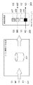
例えば、通常のカラープロファイルでの流れを図1を使って説明する。図1において、CMYK値(C1、M1、Y1、K1)の入力データ101がソースカラープロファイル102によりL*a*b*色空間の色空間データ103に変換される。このL*a*b*色空間は、入力に対するデバイス非依存の色空間である。そして、ディスティネーションカラープロファイル104により色空間データ103がCMYK値(C2、M2、Y2、K2)の出力データ105に変換される。このディスティネーションカラープロファイル104には、色空間データ103に対する出力デバイスのCMYK値の組み合わせが格納されている。
For example, the flow in a normal color profile will be described with reference to FIG. In Figure 1, are converted into CMYK values by the input data 101 (C1, M1, Y1, K1) is the source color profile 102 L * a * b *
そして、出力データ105はエンジンの階調特性の変化を補正するキャリブレーション部によりCMYK値(C2'M2'Y2'K2')のデータ106に変換される。ここでC2は1次元LUT107でC2’に、M2は1次元LUT108でM2’に、Y2は1次元LUT109でY2’に、K2は1次元LUT110でK2’にそれぞれ変換される。
The
次に、最近流通し始めたデバイスリンクプロファイルでの流れを図2を使って説明する。ここでデバイスリンクプロファイルとは、入力用プロファイルと出力用プロファイルからカラーマネージメントを用いて入力値から出力値の対応を求め、その入力値から出力値への対応テーブルが盛り込まれたプロファイルである。このプロファイルだけで入力値から出力値への色空間の変換を行うことができる。 Next, the flow of the device link profile that has recently started to be distributed will be described with reference to FIG. Here, the device link profile is a profile in which correspondence between output values is obtained from input values using color management from the input profile and output profile, and a correspondence table from the input values to the output values is incorporated. The color space can be converted from the input value to the output value only with this profile.
図2に示す入力データ101がデバイスリンクプロファイル201により、直接CMYK値(C3、M3、Y3、K3)の出力データ202に変換される。変換された出力データ202は、図1と同様に、エンジンの階調特性の変化を補正するキャリブレーション部によりCMYK値(C3'M3'Y3'K3')のデータ203に変換される。即ち、C3は1次元LUT107でC3’に、M3は1次元LUT108でM3’に、Y3は1次元LUT109でY3’に、K3は1次元LUT110でK3’にそれぞれ変換される。
The
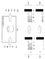
ここで、通常のカラープロファイルとデバイスリンクプロファイルとの違いを、図3、図4を用いて説明する。図3は、通常のカラープロファイルを用いた色処理を説明するための図である。図4は、デバイスリンクプロファイルを用いた色処理を説明するための図である。 Here, the difference between the normal color profile and the device link profile will be described with reference to FIGS. FIG. 3 is a diagram for explaining color processing using a normal color profile. FIG. 4 is a diagram for explaining color processing using a device link profile.
通常のカラープロファイルの場合、図3に示す301のCMYKの組み合わせと、302のCMYKの組み合わせは異なるが、ソースカラープロファイル102により変換された色空間データは同じ値(L*=5、a*=b*=0)303となる。尚、正確には、CMYの量が異なるため、明るさのL*は異なるが説明を簡単にするために同じにしている。
In the case of a normal color profile, the combination of 301 CMYK shown in FIG. 3 is different from the combination of 302 CMYK, but the color space data converted by the
この同じ色空間データ303の黒はディスティネーションカラープロファイル104により変換されると、CMYK値(C3、M3、Y3、K3)の出力データ304となる。即ち、入力の異なる301の値と302の値が出力では同じとなってしまう。そこで、違うCMYK値の入力データに対して出力データも違うようにできるようにしたものが、デバイスリンクプロファイルである。
When the black same
このデバイスリンクプロファイルは、図4に示すように、入力データのCMYK値から直接出力データのCMYK値に変換しているので、入力データ301と入力データ302を別々にハンドリングすることが可能になる。図4に示す401、402のように、入力データが異なっていれば、出力データも異なるように変換できることが一番の特徴である。
As shown in FIG. 4, since this device link profile is directly converted from the CMYK value of the input data to the CMYK value of the output data, the
即ち、通常のカラープロファイルによる処理では、例えば黒に対しての出力は、CMYKの組み合わせが同じであるが、デバイスリンクプロファイルは入力データのCMYK値の違いをそのまま出力データのCMYK値の違いに反映することができる。
しかし、最近では、キャリブレーションの精度を上げるために、CMYKをそれぞれ1次元LUTで補正するのではなく、図5に示すように、多次元LUT503を用いて補正するものが採用され始めている。1次元LUTでは、例えばキャリブレーション前、Y(Yellow)だけで再現されているものはキャリブレーションしてもYだけである。
However, recently, in order to increase the accuracy of calibration, instead of correcting each CMYK with a one-dimensional LUT, a correction using a
図5に示すように、多次元LUT503を用いた場合、CMYKに対するCMYKを定義できるので、Yだけの入力データに対しても出力データをCMYKの組み合わせに変換できる。また、色の組み合わせは保証できないが、色再現の精度を1次元LUTよりも向上させることができる。
As shown in FIG. 5, in the case of using the
しかし、図6に示すように、デバイスリンクプロファイル201によりYだけのデータ601に変換しても、多次元LUT603によりキャリブレーション後のデータ602に他の色も混じる可能性があるという欠点もある。
However, as shown in FIG. 6, even if the
本発明は、プロファイルの種類に応じて、キャリブレーションの方法を選択的に設定することを目的とする。 An object of the present invention is to selectively set a calibration method according to the type of profile.
また、本発明は、キャリブレーションの方法を選択可能にし、色再現の精度を求めるのか、出力値の組み合わせを求めるのかを選択可能にすることを目的とする。 Further, the invention allows selecting the method of calibration, or determine the accuracy of color reproduction, and an object thereof is to enable select whether obtaining the combination of the output values.
本発明は、画像処理装置であって、ページ記述言語で記述されたデータを入力する入力手段と、前記入力手段で入力されたデータのコマンドを解釈する解釈手段と、前記解釈手段にてコマンドを解釈した結果、前記データに対して色変換処理を行う際に用いるカラープロファイルとしてデバイスリンクプロファイルを用いるか否かを判定する判定手段と、前記判定手段により、前記デバイスリンクプロファイルを用いると判定されると、前記データに対してデバイスリンクプロファイルを用いて色変換処理を行い、該色変換処理後のデータに対して1次元キャリブレーションで画像補正を実行するために、1次元キャリブレーションで使用する1次元LUTを設定し、前記判定手段により、前記デバイスリンクプロファイルを用いないと判定されると、前記データに対してソースプロファイルとデスティネーションプロファイルを用いて色変換を行い、該色変換処理後のデータに対して多次元キャリブレーションで画像補正を実行するために、多次元キャリブレーションで使用する多次元LUTを設定する設定手段と、前記設定手段により設定されたLUTを用いてキャリブレーションを行い、前記色変換処理後のデータに対して、画像補正を実行する画像補正手段とを有することを特徴とする。 The present invention is an image processing apparatus , wherein an input unit that inputs data described in a page description language, an interpretation unit that interprets a command of data input by the input unit, and a command received by the interpretation unit As a result of the interpretation, a determination unit that determines whether or not to use a device link profile as a color profile used when performing color conversion processing on the data, and the determination unit determines that the device link profile is to be used. 1 is used in one-dimensional calibration to perform color conversion processing on the data using a device link profile, and to perform image correction on the data after the color conversion processing by one-dimensional calibration. Dimension LUT is set, and the determination unit determines that the device link profile is not used In order to perform color conversion on the data using a source profile and a destination profile, and to perform image correction on the data after the color conversion processing by multidimensional calibration, A setting unit that sets a multi-dimensional LUT to be used; and an image correction unit that performs calibration using the LUT set by the setting unit and performs image correction on the data after the color conversion processing. It is characterized by that.
また、本発明は、画像処理方法であって、ページ記述言語で記述されたデータを入力する入力工程と、前記入力工程において入力されたデータのコマンドを解釈する解釈工程と、前記解釈工程にてコマンドを解釈した結果、前記データに対して色変換処理を行う際に用いるカラープロファイルとしてデバイスリンクプロファイルを用いるか否かを判定する判定工程と、前記判定工程において前記デバイスリンクプロファイルを用いると判定されると、前記データに対してデバイスリンクプロファイルを用いて色変換処理を行い、該色変換処理後のデータに対して1次元キャリブレーションで画像補正を実行するために、1次元キャリブレーションで使用する1次元LUTを設定し、前記判定工程において前記デバイスリンクプロファイルを用いないと判定されると、前記データに対してソースプロファイルとデスティネーションプロファイルを用いて色変換を行い、該色変換処理後のデータに対して多次元キャリブレーションで画像補正を実行するために、多次元キャリブレーションで使用する多次元LUTを設定する設定工程と、前記設定工程において設定されたLUTを用いてキャリブレーションを行い、前記色変換処理後のデータに対して、画像補正を実行する画像補正工程とを有することを特徴とする。 Further, the present invention is an image processing method , wherein an input step for inputting data described in a page description language, an interpretation step for interpreting a command of data input in the input step, and the interpretation step As a result of interpreting the command, it is determined that a device link profile is used as a color profile used when performing color conversion processing on the data, and it is determined that the device link profile is used in the determination step. Then, color conversion processing is performed on the data using a device link profile, and the data after the color conversion processing is used in one-dimensional calibration to perform image correction by one-dimensional calibration. Set a one-dimensional LUT and use the device link profile in the determination step If it is determined that there is no data, color conversion is performed on the data using a source profile and a destination profile, and image correction is performed on the data after the color conversion processing by multidimensional calibration. A setting step for setting a multi-dimensional LUT used in the three-dimensional calibration, and an image correction for performing calibration using the LUT set in the setting step and performing image correction on the data after the color conversion processing And a process.
本発明によれば、プロファイルの種類に応じて、キャリブレーションの方法を選択的に設定することにより、単色に変換したデータに他の色が混色するのを防止することができる。 According to the present invention, depending on the type of profile, by selectively setting the calibration method, it is possible to other color data converted to monochrome is prevented from mixing.
また本発明によれば、キャリブレーションの方法を選択可能にし、色再現の精度を求めるのか、出力値の組み合わせを求めるのかを選択可能にすることで、ユーザの自由度を増大させることができる。 In addition, according to the present invention, it is possible to select a calibration method and to select whether to obtain color reproduction accuracy or a combination of output values, thereby increasing the degree of freedom of the user.
以下、図面を参照しながら発明を実施するための最良の形態について詳細に説明する。 The best mode for carrying out the invention will be described below in detail with reference to the drawings.
[第1の実施形態]
図7は、第1の実施形態における画像処理システムの構成の一例を示す図である。図7に示すように、パーソナルコンピュータ(PC)701内のアプリケーションやプリンタドライバなどで作成されたページ記述言語(PDL)データがネットワーク702を介して画像形成装置703に送られる。ここで送られたPDLデータはPDL解釈部704でPDLで書かれたコマンドが解釈され、カラープロファイルを用いて色変換が行われる。そして、変換されたデータは、随時RAM709やハードディスク(HD)707などのメモリに格納される。
[First Embodiment]
FIG. 7 is a diagram illustrating an example of the configuration of the image processing system according to the first embodiment. As shown in FIG. 7, page description language (PDL) data created by an application in a personal computer (PC) 701, a printer driver, or the like is sent to an
次に、画像処理部705でキャリブレーション補正などの画像補正が行われ、プリンタエンジン部706に送られ、プリント印刷される。また、カラープロファイルなどの各種設定はユーザインターフェース(UI)710により指定できるように構成され、それらの命令や前記各種処理の制御は中央演算部(CPU)708により制御されている。
Next, image correction such as calibration correction is performed in the
次に、色処理がカラープロファイルかデバイスリンクプロファイルかに応じて、1次元キャリブレーション又は多次元キャリブレーションを設定する処理を、図8を用いて説明する。 Next, the color processing in accordance with whether the color profile or a device link profile, a process of setting a one-dimensional calibration or multidimensional calibration will be described with reference to FIG.
図8は、第1の実施形態におけるキャリブレーション設定処理を示すフローチャートである。まず、ステップS801において、CPU708はPDL解釈部704の色処理としてデバイスリンクプロファイルを用いるか否かを判定する。その結果、デバイスリンクプロファイルを用いるのでなければ、ステップS802へ処理を進め、画像処理部705のキャリブレーションを多次元キャリブレーションに設定する。
FIG. 8 is a flowchart showing calibration setting processing in the first embodiment. First, in step S <b> 801, the
ここでは、キャリブレーション時に、多次元のためのチャートの出力や、その出力から多次元のキャリブレーションLUTの設定、実際のキャリブレーション時に多次元LUTを使用するように変更を行う。また、変更前に1次元LUTでのキャリブレーションのみしか行われておらず、多次元に初めて変更する場合は、キャリブレーションを行うように促して、補正テーブルを更新するようにする。 Here, at the time of calibration, a multi-dimensional chart is output, the multi-dimensional calibration LUT is set based on the output, and the multi-dimensional LUT is used at the time of actual calibration. Further, only the calibration in the one-dimensional LUT is performed before the change, and when changing to the multi-dimensional for the first time, the user is prompted to perform the calibration and the correction table is updated.
一方、ステップS801において、デバイスリンクプロファイルを用いるのであれば、ステップS803へ処理を進め、1次元キャリブレーションの設定を行う。具体的には、キャリブレーション時に、1次元のためのチャートの出力や、その出力から1次元のキャリブレーションLUTの設定、或いは実際のキャリブレーション時に1次元LUTを使用するように変更を行う。また、変更前に多次元LUTでのキャリブレーションのみしか行われておらず、1次元に初めて変更する場合は、キャリブレーションを行うように促して、補正テーブルを更新するようにする。 On the other hand, if a device link profile is used in step S801, the process proceeds to step S803, and one-dimensional calibration is set. Specifically, a one-dimensional chart is output during calibration, a one-dimensional calibration LUT is set from the output, or a change is made so that the one-dimensional LUT is used during actual calibration. Further, only the calibration in the multi-dimensional LUT is performed before the change, and when changing to the first dimension for the first time, the user is prompted to perform the calibration and the correction table is updated.
第1の実施形態によれば、デバイスリンクプロファイルを用いる場合、デバイスリンクプロファイルでの入力のCMYKの違いをそのまま出力のCMYKの違いに反映させてキャリブレーションを行うことができる。これにより、単色に変換したデータに他の色が混色するのを防止することが可能となる。 According to the first embodiment, when a device link profile is used, calibration can be performed by directly reflecting the difference in input CMYK in the device link profile in the difference in output CMYK. Thereby, it is possible to prevent other colors from being mixed with the data converted into a single color.
[第2の実施形態]
次に、図面を参照しながら本発明に係る第2の実施形態を詳細に説明する。第1の実施形態では、デバイスリンクプロファイルの時は、CMYK値を保存する方法を選択するだけであった。しかし、第2の実施形態では、キャリブレーションを選択可能に制御するものである。
[Second Embodiment]
Next, a second embodiment according to the present invention will be described in detail with reference to the drawings. In the first embodiment, when the device link profile is used, only the method for storing the CMYK value is selected. However, in the second embodiment, the calibration is controlled to be selectable.
尚、第2の実施形態におけるシステム構成は、図7を用いて説明した第1の実施形態と同様であり、その説明は省略する。 The system configuration in the second embodiment is the same as that in the first embodiment described with reference to FIG.
次に、デバイスリンクプロファイルを用いる場合、色味(色再現の精度)又はCMYK値(出力値の組み合わせ)の何れを優先させるかに応じて、1次元キャリブレーション又は多次元キャリブレーションを設定する処理を、図9、図10を用いて説明する。 Next, when a device link profile is used, processing for setting one-dimensional calibration or multidimensional calibration depending on whether color (accuracy of color reproduction) or CMYK value (combination of output values) is prioritized. Will be described with reference to FIGS.
図9は、第2の実施形態におけるキャリブレーション設定処理を示すフローチャートである。まず、ステップS901において、CPU708はPDL解釈部704の色処理としてデバイスリンクプロファイルを用いるか否かを判定する。その結果、デバイスリンクプロファイルを用いるのでなければ、ステップS902へ処理を進め、画像処理部705のキャリブレーションを多次元キャリブレーションに設定する。この設定処理は、第1の実施形態と同様であり、その説明は省略する。
FIG. 9 is a flowchart showing calibration setting processing in the second embodiment. First, in step S <b> 901, the
一方、ステップS901において、デバイスリンクプロファイルを用いるのであれば、ステップS903へ処理を進め、図10に示す設定画面1001をUI710の表示部に表示する。そして、デバイスリンクプロファイルキャリブレーション設定画面1001において、色味優先1002とCMYK値優先1003の何れをユーザが選択するかを待つ。ここで、ユーザが色味優先1002を選択し、OK1004を押下した場合は、ステップS902へ処理を進め、上述の多次元キャリブレーション設定処理を行う。
On the other hand, in step S901, the long used the device link profile, the process proceeds to step S903, and displays a
また、ユーザがCMYK値優先1003を選択したならば、ステップS904へ処理を進め、第1の実施形態と同様に、1次元キャリブレーションの設定を行う。
Further, if the user selects the CMYK values
第2の実施形態によれば、デバイスリンクプロファイルを用いる場合、色再現の精度を求めるのか、出力値の組み合わせを求めるのか選択可能にすることで、ユーザの自由度を増大させることが可能となる。 According to the second embodiment, when a device link profile is used, it is possible to select whether to obtain the accuracy of color reproduction or a combination of output values, thereby increasing the degree of freedom of the user. .
尚、本発明は複数の機器(例えば、ホストコンピュータ,インターフェース機器,リーダ,プリンタなど)から構成されるシステムに適用しても、1つの機器からなる装置(例えば、複写機,ファクシミリ装置など)に適用しても良い。 Even if the present invention is applied to a system composed of a plurality of devices (for example, a host computer, an interface device, a reader, a printer, etc.), it is applied to an apparatus (for example, a copier, a facsimile machine, etc.) composed of a single device. It may be applied.
また、前述した実施形態の機能を実現するソフトウェアのプログラムコードを記録した記録媒体を、システム或いは装置に供給し、そのシステム或いは装置のコンピュータ(CPU若しくはMPU)が記録媒体に格納されたプログラムコードを読出し実行する。これによっても、本発明の目的が達成されることは言うまでもない。 In addition, a recording medium in which a program code of software for realizing the functions of the above-described embodiments is recorded is supplied to the system or apparatus, and the computer (CPU or MPU) of the system or apparatus stores the program code stored in the recording medium. Read and execute. It goes without saying that the object of the present invention can also be achieved by this.
この場合、記録媒体から読出されたプログラムコード自体が前述した実施形態の機能を実現することになり、そのプログラムコードを記憶した記録媒体は本発明を構成することになる。 In this case, the program codes read from the recording medium realizes the functions of the embodiments and the recording medium storing the program code constitutes the present invention.
このプログラムコードを供給するための記録媒体として、例えばフレキシブルディスク,ハードディスク,光ディスク,光磁気ディスク,CD−ROM,CD−R,磁気テープ,不揮発性のメモリカード,ROMなどを用いることができる。 As a recording medium for supplying the program code, for example, a flexible disk, a hard disk, an optical disk, a magneto-optical disk, a CD-ROM, a CD-R, a magnetic tape, a nonvolatile memory card, a ROM, or the like can be used.
また、コンピュータが読出したプログラムコードを実行することにより、前述した実施形態の機能が実現されるだけでなく、次の場合も含まれることは言うまでもない。即ち、プログラムコードの指示に基づき、コンピュータ上で稼働しているOS(オペレーティングシステム)などが実際の処理の一部又は全部を行い、その処理により前述した実施形態の機能が実現される場合である。 In addition, by executing the program code read by the computer, not only the functions of the above-described embodiments are realized, but also the following cases are included. That is, based on instructions of the program code, is a case where such an OS (operating system) running on the computer performs part or all of the actual processing so that the functions of the embodiments mentioned above are realized by that processing .
更に、記録媒体から読出されたプログラムコードがコンピュータに挿入された機能拡張ボードやコンピュータに接続された機能拡張ユニットに備わるメモリに書込む。その後、そのプログラムコードの指示に基づき、その機能拡張ボードや機能拡張ユニットに備わるCPUなどが実際の処理の一部又は全部を行い、その処理により前述した実施形態の機能が実現される場合も含まれることは言うまでもない。 Further, the program code read from the recording medium is written in a memory provided in a function expansion board inserted into the computer or a function expansion unit connected to the computer. Then, on the basis of the instructions of the program code, the function expansion board or function expansion unit performs part or all of actual processing CPU provided in, includes the case where the functions of the above embodiments by the processing is realized Needless to say.
701 パーソナルコンピュータ(PC)
702 ネットワーク
703 画像形成装置
704 PDL解釈部
705 画像処理部
706 プリンタエンジン部
707 HD
708 CPU
709 RAM
710 ユーザインターフェース(UI)
701 Personal computer (PC)
702
708 CPU
709 RAM
710 User Interface (UI)
Claims (3)
前記入力手段で入力されたデータのコマンドを解釈する解釈手段と、
前記解釈手段にてコマンドを解釈した結果、前記データに対して色変換処理を行う際に用いるカラープロファイルとしてデバイスリンクプロファイルを用いるか否かを判定する判定手段と、
前記判定手段により、前記デバイスリンクプロファイルを用いると判定されると、前記データに対してデバイスリンクプロファイルを用いて色変換処理を行い、該色変換処理後のデータに対して1次元キャリブレーションで画像補正を実行するために、1次元キャリブレーションで使用する1次元LUTを設定し、
前記判定手段により、前記デバイスリンクプロファイルを用いないと判定されると、前記データに対してソースプロファイルとデスティネーションプロファイルを用いて色変換を行い、該色変換処理後のデータに対して多次元キャリブレーションで画像補正を実行するために、多次元キャリブレーションで使用する多次元LUTを設定する設定手段と、
前記設定手段により設定されたLUTを用いてキャリブレーションを行い、前記色変換処理後のデータに対して、画像補正を実行する画像補正手段とを有することを特徴とする画像処理装置。 An input means for inputting data described in a page description language;
Interpretation means for interpreting a command of data input by the input means;
As a result of interpreting the command by the interpretation means, a determination means for determining whether or not to use a device link profile as a color profile used when performing color conversion processing on the data;
If the determination unit determines that the device link profile is to be used, the data is subjected to color conversion processing using the device link profile, and the image after the color conversion processing is subjected to an image by one-dimensional calibration. In order to perform correction, a one-dimensional LUT used for one-dimensional calibration is set,
If the determination unit determines that the device link profile is not used, the data is subjected to color conversion using the source profile and the destination profile, and the data after the color conversion processing is subjected to multidimensional calibration. Setting means for setting a multidimensional LUT used in multidimensional calibration in order to perform image correction in
An image processing apparatus comprising: an image correcting unit that performs calibration using the LUT set by the setting unit and performs image correction on the data after the color conversion processing .
前記入力工程において入力されたデータのコマンドを解釈する解釈工程と、
前記解釈工程にてコマンドを解釈した結果、前記データに対して色変換処理を行う際に用いるカラープロファイルとしてデバイスリンクプロファイルを用いるか否かを判定する判定工程と、
前記判定工程において前記デバイスリンクプロファイルを用いると判定されると、前記データに対してデバイスリンクプロファイルを用いて色変換処理を行い、該色変換処理後のデータに対して1次元キャリブレーションで画像補正を実行するために、1次元キャリブレーションで使用する1次元LUTを設定し、
前記判定工程において前記デバイスリンクプロファイルを用いないと判定されると、前記データに対してソースプロファイルとデスティネーションプロファイルを用いて色変換を行い、該色変換処理後のデータに対して多次元キャリブレーションで画像補正を実行するために、多次元キャリブレーションで使用する多次元LUTを設定する設定工程と、
前記設定工程において設定されたLUTを用いてキャリブレーションを行い、前記色変換処理後のデータに対して、画像補正を実行する画像補正工程とを有することを特徴とする画像処理方法。 An input process for inputting data described in a page description language;
An interpreting step of interpreting a command of data input in the input step;
As a result of interpreting the command in the interpretation step, a determination step for determining whether or not to use a device link profile as a color profile used when performing color conversion processing on the data;
If it is determined in the determination step that the device link profile is used, the data is subjected to color conversion processing using the device link profile, and image correction is performed on the data after the color conversion processing by one-dimensional calibration. To set a one-dimensional LUT to be used for one-dimensional calibration,
If it is determined that the device link profile is not used in the determination step, color conversion is performed on the data using a source profile and a destination profile, and multi-dimensional calibration is performed on the data after the color conversion processing. A setting step for setting a multi-dimensional LUT used in multi-dimensional calibration in order to perform image correction in
An image processing method comprising: an image correction step of performing calibration using the LUT set in the setting step and performing image correction on the data after the color conversion processing .
Priority Applications (2)
| Application Number | Priority Date | Filing Date | Title |
|---|---|---|---|
| JP2006207164A JP4677379B2 (en) | 2006-07-28 | 2006-07-28 | Image processing apparatus and image processing method |
| US11/776,586 US7944583B2 (en) | 2006-07-28 | 2007-07-12 | Image processing apparatus and method |
Applications Claiming Priority (1)
| Application Number | Priority Date | Filing Date | Title |
|---|---|---|---|
| JP2006207164A JP4677379B2 (en) | 2006-07-28 | 2006-07-28 | Image processing apparatus and image processing method |
Publications (3)
| Publication Number | Publication Date |
|---|---|
| JP2008035270A JP2008035270A (en) | 2008-02-14 |
| JP2008035270A5 JP2008035270A5 (en) | 2009-09-10 |
| JP4677379B2 true JP4677379B2 (en) | 2011-04-27 |
Family
ID=38985931
Family Applications (1)
| Application Number | Title | Priority Date | Filing Date |
|---|---|---|---|
| JP2006207164A Expired - Fee Related JP4677379B2 (en) | 2006-07-28 | 2006-07-28 | Image processing apparatus and image processing method |
Country Status (2)
| Country | Link |
|---|---|
| US (1) | US7944583B2 (en) |
| JP (1) | JP4677379B2 (en) |
Cited By (2)
| Publication number | Priority date | Publication date | Assignee | Title |
|---|---|---|---|---|
| US9223241B2 (en) | 2012-06-26 | 2015-12-29 | Canon Kabushiki Kaisha | Image processing apparatus and image processing method |
| KR101667666B1 (en) * | 2012-07-11 | 2016-10-28 | 캐논 가부시끼가이샤 | Image processing apparatus and method for calibrating the same |
Families Citing this family (10)
| Publication number | Priority date | Publication date | Assignee | Title |
|---|---|---|---|---|
| JP2009274273A (en) * | 2008-05-13 | 2009-11-26 | Canon Inc | Image processing device, image processing method, and program |
| JP5121786B2 (en) * | 2009-07-10 | 2013-01-16 | キヤノン株式会社 | Image processing method, image processing apparatus, and program |
| US8665491B2 (en) * | 2011-01-06 | 2014-03-04 | Infoprint Solutions Company, Llc | Mechanism for applying formula based transformations in a color management workflow |
| JP5578147B2 (en) * | 2011-08-11 | 2014-08-27 | コニカミノルタ株式会社 | Printing system, printing method, and printing program |
| JP5842599B2 (en) * | 2011-12-22 | 2016-01-13 | コニカミノルタ株式会社 | Print job processing apparatus, printing system, print job processing system, and program |
| JP6193589B2 (en) * | 2013-03-05 | 2017-09-06 | キヤノン株式会社 | Image processing apparatus, image processing method, and program for executing image processing method |
| JP6558888B2 (en) | 2014-03-04 | 2019-08-14 | キヤノン株式会社 | Apparatus, printing apparatus, printing control method, and program |
| CN106157955A (en) * | 2015-03-30 | 2016-11-23 | 阿里巴巴集团控股有限公司 | A kind of sound control method and device |
| US10319119B2 (en) * | 2016-03-08 | 2019-06-11 | Siemens Healthcare Gmbh | Methods and systems for accelerated reading of a 3D medical volume |
| JP7167693B2 (en) * | 2018-12-20 | 2022-11-09 | 東洋紡株式会社 | LAMINATED FILM, LAMINATE, AND LAMINATE MANUFACTURING METHOD |
Citations (4)
| Publication number | Priority date | Publication date | Assignee | Title |
|---|---|---|---|---|
| JP2001103330A (en) * | 1999-07-28 | 2001-04-13 | Fuji Photo Film Co Ltd | Color conversion table generating method and device, and proof generator using the device |
| JP2004023740A (en) * | 2002-06-20 | 2004-01-22 | Canon Inc | Data processing apparatus and method, and image processing apparatus |
| JP2005340926A (en) * | 2004-05-24 | 2005-12-08 | Canon Inc | Image processing method in image processing apparatus, and image processing apparatus |
| JP2006148831A (en) * | 2004-11-25 | 2006-06-08 | Konica Minolta Medical & Graphic Inc | Image output method, image output control apparatus, image output system, image output program, and storage medium with the program stored thereon |
Family Cites Families (4)
| Publication number | Priority date | Publication date | Assignee | Title |
|---|---|---|---|---|
| US7298527B2 (en) * | 2003-03-12 | 2007-11-20 | Canon Kabushiki Kaisha | Image forming apparatus and its control method, and computer program |
| US20050259280A1 (en) * | 2004-05-05 | 2005-11-24 | Kodak Polychrome Graphics, Llc | Color management of halftone prints |
| US7667872B2 (en) * | 2005-11-14 | 2010-02-23 | Microsoft Corporation | Gamut mapping and rendering intent management system |
| JP5538743B2 (en) * | 2009-04-15 | 2014-07-02 | キヤノン株式会社 | Image processing apparatus, image processing method, and program |
-
2006
- 2006-07-28 JP JP2006207164A patent/JP4677379B2/en not_active Expired - Fee Related
-
2007
- 2007-07-12 US US11/776,586 patent/US7944583B2/en not_active Expired - Fee Related
Patent Citations (4)
| Publication number | Priority date | Publication date | Assignee | Title |
|---|---|---|---|---|
| JP2001103330A (en) * | 1999-07-28 | 2001-04-13 | Fuji Photo Film Co Ltd | Color conversion table generating method and device, and proof generator using the device |
| JP2004023740A (en) * | 2002-06-20 | 2004-01-22 | Canon Inc | Data processing apparatus and method, and image processing apparatus |
| JP2005340926A (en) * | 2004-05-24 | 2005-12-08 | Canon Inc | Image processing method in image processing apparatus, and image processing apparatus |
| JP2006148831A (en) * | 2004-11-25 | 2006-06-08 | Konica Minolta Medical & Graphic Inc | Image output method, image output control apparatus, image output system, image output program, and storage medium with the program stored thereon |
Cited By (3)
| Publication number | Priority date | Publication date | Assignee | Title |
|---|---|---|---|---|
| US9223241B2 (en) | 2012-06-26 | 2015-12-29 | Canon Kabushiki Kaisha | Image processing apparatus and image processing method |
| KR101667666B1 (en) * | 2012-07-11 | 2016-10-28 | 캐논 가부시끼가이샤 | Image processing apparatus and method for calibrating the same |
| US9542629B2 (en) | 2012-07-11 | 2017-01-10 | Canon Kabushiki Kaisha | Image processing apparatus, image processing method, and program |
Also Published As
| Publication number | Publication date |
|---|---|
| JP2008035270A (en) | 2008-02-14 |
| US20080024844A1 (en) | 2008-01-31 |
| US7944583B2 (en) | 2011-05-17 |
Similar Documents
| Publication | Publication Date | Title |
|---|---|---|
| JP4677379B2 (en) | Image processing apparatus and image processing method | |
| KR100850057B1 (en) | Image processing apparatus and image processing method | |
| US8422070B2 (en) | Image processing apparatus, method, and computer readable storage medium for toner reduction based on image data type and area size | |
| US7920308B2 (en) | Image processing apparatus and image processing method | |
| JP5344518B2 (en) | Image processing method and image processing apparatus | |
| JP2002359748A (en) | Medium for recording color transformation program, color transformation program, method for generating color transformation table, medium for recording color transformation table data, color transformation device, color transformation method and color transformation table | |
| JP2006217181A (en) | Color processing device and method | |
| US20100123911A1 (en) | Print color management | |
| JP2009099129A (en) | Image forming system, image processing apparatus, and image processing method | |
| US9218552B2 (en) | Image processing apparatus and image processing method | |
| JP2010288250A (en) | Image processing apparatus and method, program, and recording medium | |
| JP5391861B2 (en) | Image forming apparatus, color conversion control method, color conversion control program, and information processing apparatus having printer driver | |
| CN114070952A (en) | Information processing apparatus, information processing method, and storage medium | |
| US20190052774A1 (en) | Image processing apparatus, image processing method, and storage medium | |
| JP2005243003A (en) | Image processing method and image processor | |
| JP2012109884A (en) | Color conversion table management method, color conversion table management device and program | |
| KR101631942B1 (en) | Method for printing document based on Black Optimization printing option and for controlling thereof, image forming apparatus and host device for performing thereof | |
| JP7479841B2 (en) | Control device, control method and program | |
| JP2003234916A (en) | Image processing apparatus, image processing method, printer, image processing program and medium recording image processing program | |
| JP2010274616A (en) | Image processing system, image processing device, image forming apparatus and program | |
| US8792135B2 (en) | Image processing device, computer program product including image processing program embodied on computer readable medium, and image forming apparatus | |
| JP4821142B2 (en) | Image processing system | |
| JP2011249931A (en) | Image forming system and image forming program | |
| JP2005018524A (en) | Method for controlling printing | |
| JP5678559B2 (en) | Information processing apparatus and information processing program |
Legal Events
| Date | Code | Title | Description |
|---|---|---|---|
| A521 | Request for written amendment filed |
Free format text: JAPANESE INTERMEDIATE CODE: A523 Effective date: 20090728 |
|
| A621 | Written request for application examination |
Free format text: JAPANESE INTERMEDIATE CODE: A621 Effective date: 20090728 |
|
| A977 | Report on retrieval |
Free format text: JAPANESE INTERMEDIATE CODE: A971007 Effective date: 20101014 |
|
| A131 | Notification of reasons for refusal |
Free format text: JAPANESE INTERMEDIATE CODE: A131 Effective date: 20101025 |
|
| A521 | Request for written amendment filed |
Free format text: JAPANESE INTERMEDIATE CODE: A523 Effective date: 20101224 |
|
| TRDD | Decision of grant or rejection written | ||
| A01 | Written decision to grant a patent or to grant a registration (utility model) |
Free format text: JAPANESE INTERMEDIATE CODE: A01 Effective date: 20110121 |
|
| A01 | Written decision to grant a patent or to grant a registration (utility model) |
Free format text: JAPANESE INTERMEDIATE CODE: A01 |
|
| A61 | First payment of annual fees (during grant procedure) |
Free format text: JAPANESE INTERMEDIATE CODE: A61 Effective date: 20110131 |
|
| FPAY | Renewal fee payment (event date is renewal date of database) |
Free format text: PAYMENT UNTIL: 20140204 Year of fee payment: 3 |
|
| R150 | Certificate of patent or registration of utility model |
Ref document number: 4677379 Country of ref document: JP Free format text: JAPANESE INTERMEDIATE CODE: R150 Free format text: JAPANESE INTERMEDIATE CODE: R150 |
|
| LAPS | Cancellation because of no payment of annual fees |