JP4677205B2 - Guide wire - Google Patents
Guide wire Download PDFInfo
- Publication number
- JP4677205B2 JP4677205B2 JP2004167575A JP2004167575A JP4677205B2 JP 4677205 B2 JP4677205 B2 JP 4677205B2 JP 2004167575 A JP2004167575 A JP 2004167575A JP 2004167575 A JP2004167575 A JP 2004167575A JP 4677205 B2 JP4677205 B2 JP 4677205B2
- Authority
- JP
- Japan
- Prior art keywords
- coil
- end side
- guide wire
- distal end
- fixing member
- Prior art date
- Legal status (The legal status is an assumption and is not a legal conclusion. Google has not performed a legal analysis and makes no representation as to the accuracy of the status listed.)
- Expired - Lifetime
Links
- 239000011162 core material Substances 0.000 claims description 208
- 239000000463 material Substances 0.000 claims description 74
- 238000003466 welding Methods 0.000 claims description 21
- 239000000853 adhesive Substances 0.000 claims description 15
- 230000001070 adhesive effect Effects 0.000 claims description 15
- 238000002844 melting Methods 0.000 claims description 13
- 230000008018 melting Effects 0.000 claims description 13
- 230000000704 physical effect Effects 0.000 claims description 8
- 238000003780 insertion Methods 0.000 abstract description 8
- 230000037431 insertion Effects 0.000 abstract description 8
- 230000002349 favourable effect Effects 0.000 abstract description 2
- 239000000956 alloy Substances 0.000 description 40
- 229910045601 alloy Inorganic materials 0.000 description 39
- 239000010935 stainless steel Substances 0.000 description 17
- 229910001220 stainless steel Inorganic materials 0.000 description 17
- BASFCYQUMIYNBI-UHFFFAOYSA-N platinum Chemical compound [Pt] BASFCYQUMIYNBI-UHFFFAOYSA-N 0.000 description 14
- 238000005219 brazing Methods 0.000 description 13
- 239000000470 constituent Substances 0.000 description 11
- 229910000679 solder Inorganic materials 0.000 description 10
- 230000005540 biological transmission Effects 0.000 description 8
- KHYBPSFKEHXSLX-UHFFFAOYSA-N iminotitanium Chemical compound [Ti]=N KHYBPSFKEHXSLX-UHFFFAOYSA-N 0.000 description 8
- 239000010410 layer Substances 0.000 description 8
- 238000000034 method Methods 0.000 description 8
- 229910001000 nickel titanium Inorganic materials 0.000 description 8
- 229910052697 platinum Inorganic materials 0.000 description 7
- 229920005989 resin Polymers 0.000 description 7
- 239000011347 resin Substances 0.000 description 7
- 229910018487 Ni—Cr Inorganic materials 0.000 description 6
- -1 and Polymers 0.000 description 6
- 239000002131 composite material Substances 0.000 description 6
- PCHJSUWPFVWCPO-UHFFFAOYSA-N gold Chemical compound [Au] PCHJSUWPFVWCPO-UHFFFAOYSA-N 0.000 description 6
- 229910052737 gold Inorganic materials 0.000 description 6
- 239000010931 gold Substances 0.000 description 6
- 239000007769 metal material Substances 0.000 description 6
- 229920002050 silicone resin Polymers 0.000 description 6
- 238000005452 bending Methods 0.000 description 5
- 210000004204 blood vessel Anatomy 0.000 description 5
- 239000011248 coating agent Substances 0.000 description 5
- 238000000576 coating method Methods 0.000 description 5
- 239000000203 mixture Substances 0.000 description 5
- 229910000510 noble metal Inorganic materials 0.000 description 5
- 239000002861 polymer material Substances 0.000 description 5
- YCKRFDGAMUMZLT-UHFFFAOYSA-N Fluorine atom Chemical compound [F] YCKRFDGAMUMZLT-UHFFFAOYSA-N 0.000 description 4
- 230000000694 effects Effects 0.000 description 4
- 239000011737 fluorine Substances 0.000 description 4
- 229910052731 fluorine Inorganic materials 0.000 description 4
- 229920000728 polyester Polymers 0.000 description 4
- 229910000531 Co alloy Inorganic materials 0.000 description 3
- RYGMFSIKBFXOCR-UHFFFAOYSA-N Copper Chemical compound [Cu] RYGMFSIKBFXOCR-UHFFFAOYSA-N 0.000 description 3
- 229920003171 Poly (ethylene oxide) Polymers 0.000 description 3
- 239000004952 Polyamide Substances 0.000 description 3
- 229920001577 copolymer Polymers 0.000 description 3
- 229910052802 copper Inorganic materials 0.000 description 3
- 239000010949 copper Substances 0.000 description 3
- 229910052759 nickel Inorganic materials 0.000 description 3
- 229920002401 polyacrylamide Polymers 0.000 description 3
- 229920002647 polyamide Polymers 0.000 description 3
- 229920002635 polyurethane Polymers 0.000 description 3
- 239000004814 polyurethane Substances 0.000 description 3
- 239000000126 substance Substances 0.000 description 3
- 238000006467 substitution reaction Methods 0.000 description 3
- RTZKZFJDLAIYFH-UHFFFAOYSA-N Diethyl ether Chemical compound CCOCC RTZKZFJDLAIYFH-UHFFFAOYSA-N 0.000 description 2
- 239000004677 Nylon Substances 0.000 description 2
- 239000004698 Polyethylene Substances 0.000 description 2
- 239000004642 Polyimide Substances 0.000 description 2
- 239000004743 Polypropylene Substances 0.000 description 2
- 239000004793 Polystyrene Substances 0.000 description 2
- 239000004372 Polyvinyl alcohol Substances 0.000 description 2
- BQCADISMDOOEFD-UHFFFAOYSA-N Silver Chemical compound [Ag] BQCADISMDOOEFD-UHFFFAOYSA-N 0.000 description 2
- 229920002125 Sokalan® Polymers 0.000 description 2
- 238000010521 absorption reaction Methods 0.000 description 2
- 230000004323 axial length Effects 0.000 description 2
- 230000008901 benefit Effects 0.000 description 2
- 229910052790 beryllium Inorganic materials 0.000 description 2
- 229920003174 cellulose-based polymer Polymers 0.000 description 2
- 239000003795 chemical substances by application Substances 0.000 description 2
- 229910052804 chromium Inorganic materials 0.000 description 2
- 239000011247 coating layer Substances 0.000 description 2
- 230000007423 decrease Effects 0.000 description 2
- 230000003247 decreasing effect Effects 0.000 description 2
- 229920000840 ethylene tetrafluoroethylene copolymer Polymers 0.000 description 2
- 238000010438 heat treatment Methods 0.000 description 2
- 230000006872 improvement Effects 0.000 description 2
- FPYJFEHAWHCUMM-UHFFFAOYSA-N maleic anhydride Chemical compound O=C1OC(=O)C=C1 FPYJFEHAWHCUMM-UHFFFAOYSA-N 0.000 description 2
- 229920001778 nylon Polymers 0.000 description 2
- 239000013500 performance material Substances 0.000 description 2
- XNGIFLGASWRNHJ-UHFFFAOYSA-N phthalic acid Chemical compound OC(=O)C1=CC=CC=C1C(O)=O XNGIFLGASWRNHJ-UHFFFAOYSA-N 0.000 description 2
- 229920003023 plastic Polymers 0.000 description 2
- 239000004033 plastic Substances 0.000 description 2
- 239000004417 polycarbonate Substances 0.000 description 2
- 229920000515 polycarbonate Polymers 0.000 description 2
- 229920000573 polyethylene Polymers 0.000 description 2
- 229920001721 polyimide Polymers 0.000 description 2
- 229920000642 polymer Polymers 0.000 description 2
- 229920000098 polyolefin Polymers 0.000 description 2
- 229920001155 polypropylene Polymers 0.000 description 2
- 229920002223 polystyrene Polymers 0.000 description 2
- 229920001343 polytetrafluoroethylene Polymers 0.000 description 2
- 239000004810 polytetrafluoroethylene Substances 0.000 description 2
- 229920002451 polyvinyl alcohol Polymers 0.000 description 2
- 239000004800 polyvinyl chloride Substances 0.000 description 2
- 229920000915 polyvinyl chloride Polymers 0.000 description 2
- 229920000036 polyvinylpyrrolidone Polymers 0.000 description 2
- 239000001267 polyvinylpyrrolidone Substances 0.000 description 2
- 235000013855 polyvinylpyrrolidone Nutrition 0.000 description 2
- 229920002379 silicone rubber Polymers 0.000 description 2
- 239000004945 silicone rubber Substances 0.000 description 2
- 229910052709 silver Inorganic materials 0.000 description 2
- 239000004332 silver Substances 0.000 description 2
- 125000006850 spacer group Chemical group 0.000 description 2
- 230000009466 transformation Effects 0.000 description 2
- XLYOFNOQVPJJNP-UHFFFAOYSA-N water Substances O XLYOFNOQVPJJNP-UHFFFAOYSA-N 0.000 description 2
- HRPVXLWXLXDGHG-UHFFFAOYSA-N Acrylamide Chemical compound NC(=O)C=C HRPVXLWXLXDGHG-UHFFFAOYSA-N 0.000 description 1
- NIXOWILDQLNWCW-UHFFFAOYSA-M Acrylate Chemical compound [O-]C(=O)C=C NIXOWILDQLNWCW-UHFFFAOYSA-M 0.000 description 1
- 229910000851 Alloy steel Inorganic materials 0.000 description 1
- PKAUISBSZACZJI-UHFFFAOYSA-N CC(=CC(=O)N)C.C(C(=C)C)(=O)O Chemical compound CC(=CC(=O)N)C.C(C(=C)C)(=O)O PKAUISBSZACZJI-UHFFFAOYSA-N 0.000 description 1
- 229910017518 Cu Zn Inorganic materials 0.000 description 1
- 229910017752 Cu-Zn Inorganic materials 0.000 description 1
- 229910017943 Cu—Zn Inorganic materials 0.000 description 1
- 229920000663 Hydroxyethyl cellulose Polymers 0.000 description 1
- 239000004354 Hydroxyethyl cellulose Substances 0.000 description 1
- 229920002153 Hydroxypropyl cellulose Polymers 0.000 description 1
- 229910001182 Mo alloy Inorganic materials 0.000 description 1
- 229910003310 Ni-Al Inorganic materials 0.000 description 1
- 239000002202 Polyethylene glycol Substances 0.000 description 1
- 229920002873 Polyethylenimine Polymers 0.000 description 1
- CDBYLPFSWZWCQE-UHFFFAOYSA-L Sodium Carbonate Chemical compound [Na+].[Na+].[O-]C([O-])=O CDBYLPFSWZWCQE-UHFFFAOYSA-L 0.000 description 1
- 206010057469 Vascular stenosis Diseases 0.000 description 1
- 229910052782 aluminium Inorganic materials 0.000 description 1
- 238000002583 angiography Methods 0.000 description 1
- 230000015572 biosynthetic process Effects 0.000 description 1
- 229920001400 block copolymer Polymers 0.000 description 1
- 229910017052 cobalt Inorganic materials 0.000 description 1
- 239000010941 cobalt Substances 0.000 description 1
- GUTLYIVDDKVIGB-UHFFFAOYSA-N cobalt atom Chemical compound [Co] GUTLYIVDDKVIGB-UHFFFAOYSA-N 0.000 description 1
- TVZPLCNGKSPOJA-UHFFFAOYSA-N copper zinc Chemical compound [Cu].[Zn] TVZPLCNGKSPOJA-UHFFFAOYSA-N 0.000 description 1
- 238000007887 coronary angioplasty Methods 0.000 description 1
- 230000008878 coupling Effects 0.000 description 1
- 238000010168 coupling process Methods 0.000 description 1
- 238000005859 coupling reaction Methods 0.000 description 1
- 238000006073 displacement reaction Methods 0.000 description 1
- 229920001971 elastomer Polymers 0.000 description 1
- 239000000806 elastomer Substances 0.000 description 1
- KNVWWMVPZMGMPG-UHFFFAOYSA-N formaldehyde;3-methylbutan-2-one Chemical compound O=C.CC(C)C(C)=O KNVWWMVPZMGMPG-UHFFFAOYSA-N 0.000 description 1
- 229910052733 gallium Inorganic materials 0.000 description 1
- 235000019447 hydroxyethyl cellulose Nutrition 0.000 description 1
- 239000001863 hydroxypropyl cellulose Substances 0.000 description 1
- 235000010977 hydroxypropyl cellulose Nutrition 0.000 description 1
- 238000001727 in vivo Methods 0.000 description 1
- 229920006276 ketonic resin Polymers 0.000 description 1
- 229910052751 metal Inorganic materials 0.000 description 1
- 239000002184 metal Substances 0.000 description 1
- 229910052750 molybdenum Inorganic materials 0.000 description 1
- 229910052758 niobium Inorganic materials 0.000 description 1
- 230000002093 peripheral effect Effects 0.000 description 1
- XNGIFLGASWRNHJ-UHFFFAOYSA-L phthalate(2-) Chemical compound [O-]C(=O)C1=CC=CC=C1C([O-])=O XNGIFLGASWRNHJ-UHFFFAOYSA-L 0.000 description 1
- 229920001467 poly(styrenesulfonates) Polymers 0.000 description 1
- 239000004584 polyacrylic acid Substances 0.000 description 1
- 229920001223 polyethylene glycol Polymers 0.000 description 1
- 229920002338 polyhydroxyethylmethacrylate Polymers 0.000 description 1
- 229960002796 polystyrene sulfonate Drugs 0.000 description 1
- 239000011970 polystyrene sulfonate Substances 0.000 description 1
- 239000010970 precious metal Substances 0.000 description 1
- 150000003151 propanoic acid esters Chemical class 0.000 description 1
- 229910052710 silicon Inorganic materials 0.000 description 1
- 239000002345 surface coating layer Substances 0.000 description 1
- 238000001356 surgical procedure Methods 0.000 description 1
- 229910052715 tantalum Inorganic materials 0.000 description 1
- 229920002725 thermoplastic elastomer Polymers 0.000 description 1
- 229910052718 tin Inorganic materials 0.000 description 1
- 229910052719 titanium Inorganic materials 0.000 description 1
- 230000007704 transition Effects 0.000 description 1
- 229920003169 water-soluble polymer Polymers 0.000 description 1
- 238000009736 wetting Methods 0.000 description 1
- 229910052725 zinc Inorganic materials 0.000 description 1
Images


Classifications
-
- A—HUMAN NECESSITIES
- A61—MEDICAL OR VETERINARY SCIENCE; HYGIENE
- A61M—DEVICES FOR INTRODUCING MEDIA INTO, OR ONTO, THE BODY; DEVICES FOR TRANSDUCING BODY MEDIA OR FOR TAKING MEDIA FROM THE BODY; DEVICES FOR PRODUCING OR ENDING SLEEP OR STUPOR
- A61M25/00—Catheters; Hollow probes
- A61M25/01—Introducing, guiding, advancing, emplacing or holding catheters
- A61M25/09—Guide wires
- A61M2025/09058—Basic structures of guide wires
- A61M2025/09083—Basic structures of guide wires having a coil around a core
Landscapes
- Health & Medical Sciences (AREA)
- Life Sciences & Earth Sciences (AREA)
- Biophysics (AREA)
- Pulmonology (AREA)
- Engineering & Computer Science (AREA)
- Anesthesiology (AREA)
- Biomedical Technology (AREA)
- Heart & Thoracic Surgery (AREA)
- Hematology (AREA)
- Animal Behavior & Ethology (AREA)
- General Health & Medical Sciences (AREA)
- Public Health (AREA)
- Veterinary Medicine (AREA)
- Media Introduction/Drainage Providing Device (AREA)
- Inorganic Fibers (AREA)
Abstract
Description
本発明は、ガイドワイヤに関するものである。特に、血管などの体腔内にカテーテルを導入する際に用いられるガイドワイヤに関する。 The present invention relates to a guide wire. In particular, the present invention relates to a guide wire used when a catheter is introduced into a body cavity such as a blood vessel.
ガイドワイヤは、例えばPTCA術(Percutaneous Transluminal Coronary Angioplasty:経皮的冠状動脈血管形成術)のような、外科的手術が困難な部位の治療、または人体への低侵襲を目的とした治療や、心臓血管造影などの検査に用いられるカテーテルを誘導するのに使用される。PTCA術に用いられるガイドワイヤは、ガイドワイヤの先端をバルーンカテーテルの先端より突出させた状態にて、バルーンカテーテルと共に目的部位である血管狭窄部付近まで挿入され、バルーンカテーテルの先端部を血管狭窄部付近まで誘導する。
血管は、複雑に湾曲しており、バルーンカテーテルを血管に挿入する際に用いるガイドワイヤには、適度の曲げに対する柔軟性および復元性、基端部における操作を先端側に伝達するための押し込み性およびトルク伝達性(これらを総称して「操作性」という)、さらには耐キンク性(耐折れ曲がり性)等が要求される。
それらの特性の内、適度の柔軟性を得るための構造として、ガイドワイヤの細い先端芯材の回りに曲げに対する柔軟性を有する金属コイルを備えたものや、柔軟性および復元性を付与するためのガイドワイヤの芯材にNi−Ti等の超弾性線を用いたものがある。
前者のコイルを備えたガイドワイヤには、特許文献1のように、2つの材質の異なるコイルを直列に配置して相互にねじ込まれて芯材に固定されたものがある。しかし、コイルをガイドワイヤの芯材の固定する際に、コイルの中心に固定するのは必ずしも容易な作業とは言えなかった。
The guide wire can be used for the treatment of a site where surgical operation is difficult, such as PTCA (Percutaneous Transluminal Coronary Angioplasty), or for the purpose of minimally invasive to the human body, Used to guide catheters used for examinations such as angiography. A guide wire used for PTCA surgery is inserted to the vicinity of the target vascular stenosis portion together with the balloon catheter with the tip of the guide wire protruding from the tip of the balloon catheter. Guide to near.
The blood vessel is intricately curved, and the guide wire used to insert the balloon catheter into the blood vessel has flexibility and resilience to moderate bending, and pushability to transmit the operation at the proximal end to the distal side. In addition, torque transmission properties (collectively referred to as “operability”) and kink resistance (bending resistance) are required.
Among these characteristics, as a structure for obtaining moderate flexibility, a structure having a metal coil having flexibility for bending around a thin tip core material of a guide wire, and for providing flexibility and resilience There is a guide wire using a super elastic wire such as Ni-Ti as a core material.
As for the guide wire provided with the former coil, there is one in which two different coils are arranged in series and screwed to each other and fixed to a core material as in Patent Document 1. However, it is not always easy to fix the coil to the center of the coil when fixing the core material of the guide wire.
そこで、特許文献2には、ガイドワイヤにおいて、2つのコイルを心出しモールド上にて結合した後、該モールドを取り除くことが開示されている。また、特許文献3には、接続コイルを介して2つのコイルを接続したガイドワイヤが開示されている。さらに、特許文献4には、2つのコイルのスぺーサーを介して結合したガイドワイヤとが開示されている。
しかし、上記特許文献1において2つのコイルを芯材に接合しようとすると、はんだがコイルと芯材の空間を流れてしまい、接合部が軸方向に長くなってしまう。また、特許文献2や3のように、モールドや接続コイル上にて結合する方法では、コイル同士の軸線上のずれは少なくなるが、作業が煩雑であり、かつ、接合したコイルを芯材に接続しようとすると、コイルの中心軸と芯材とがずれるという問題点は残る。特許文献4のスぺーサーには、造影性などの特徴はあるものの、コイル同士のズレやコイルと芯材とのズレという点ではなんら示唆もない。
Therefore,
However, when the two coils are joined to the core in Patent Document 1, the solder flows through the space between the coil and the core, and the joint becomes long in the axial direction. Further, as in
本発明の目的は、コイルを芯材に対して、ほぼ同心状となるように配置することができ、生体内挿入時に、ガイドワイヤの先端部は、偏りのない良好な変形を生じ、操作性の優れたガイドワイヤを提供するものである。 The object of the present invention is that the coil can be arranged so as to be substantially concentric with respect to the core material, and the distal end portion of the guide wire undergoes good deformation with no bias when inserted into the living body, thereby improving operability. An excellent guide wire is provided.
上記目的を達成するものは、以下のものである。
(1) 芯材と、該芯材の少なくとも先端側部分を被包するコイルとを備えるガイドワイヤであって、該ガイドワイヤは、前記芯材の先端側部分に固定されるとともに、前記コイルの長手方向の少なくとも一部分にて、該コイルを前記芯材に対してほぼ同心状となるよう固定するためのコイル固定用部材を備え、前記コイルは、先端側コイルと基端側コイルとを備え、さらに、前記先端側コイルおよび前記基端側コイルは、ほぼ同じ外径を有するとともに異なる内径を有し、前記コイル固定用部材は、前記先端側コイルの基端部および前記基端側コイルの先端部を前記芯材に固定するものであり、かつ、前記コイルは、前記コイル固定用部材に接着用材料を介して固定されているガイドワイヤ。
(2) 前記先端側コイルと前記基端側コイルとは、物性が異なっている上記(1)に記載のガイドワイヤ。
(3) 前記コイル固定用部材は、前記各コイルの内径の相違に対応する小径部分と大径部分を備えている上記(1)に記載のガイドワイヤ。
(4) 芯材と、該芯材の少なくとも先端側部分を被包するコイルとを備えるガイドワイヤであって、該ガイドワイヤは、前記芯材の先端側部分に固定されるとともに、前記コイルの長手方向の少なくとも一部分にて、該コイルを前記芯材に対してほぼ同心状となるよう固定するためのコイル固定用部材を備え、前記コイルは、先端側コイルと基端側コイルとを備え、さらに、前記先端側コイルおよび前記基端側コイルは、ほぼ同じ外径を有するとともに異なる内径を有し、前記コイル固定用部材は、前記先端側コイルの基端部および前記基端側コイルの先端部を前記芯材に固定するものであり、かつ、前記コイルは、前記コイル固定用部材に溶接により固定されているガイドワイヤ。
(5) 前記コイル固定用部材形成材料の融点は、前記コイル形成材料の融点よりも低いものである(4)に記載のガイドワイヤ。
(6) 前記コイル固定用部材は、前記各コイルの内径の相違に対応する小径部分と大径部分を備えている(4)または(5)に記載のガイドワイヤ。
(7) 前記先端側コイルと前記基端側コイルとは、物性が異なっている上記(4)ないし(6)のいずれかに記載のガイドワイヤ。
What achieves the above object is as follows.
(1) A guide wire comprising a core material and a coil that encapsulates at least a tip side portion of the core material, the guide wire being fixed to the tip side portion of the core material, A coil fixing member for fixing the coil so as to be substantially concentric with the core material in at least a part of the longitudinal direction, the coil including a distal end side coil and a proximal end side coil; Furthermore, the distal end side coil and the proximal end side coil have substantially the same outer diameter and different inner diameters, and the coil fixing member includes a proximal end portion of the distal end side coil and a distal end of the proximal end side coil. A guide wire that fixes a portion to the core member, and the coil is fixed to the coil fixing member via an adhesive material.
( 2 ) The guide wire according to (1), wherein the distal end side coil and the proximal end side coil have different physical properties.
( 3 ) The guide wire according to (1), wherein the coil fixing member includes a small diameter portion and a large diameter portion corresponding to a difference in inner diameter of each coil.
( 4 ) A guide wire comprising a core material and a coil that encapsulates at least the tip side portion of the core material, the guide wire being fixed to the tip side portion of the core material, A coil fixing member for fixing the coil so as to be substantially concentric with the core material in at least a part of the longitudinal direction, the coil including a distal end side coil and a proximal end side coil; Furthermore, the distal end side coil and the proximal end side coil have substantially the same outer diameter and different inner diameters, and the coil fixing member includes a proximal end portion of the distal end side coil and a distal end of the proximal end side coil. A guide wire that fixes a portion to the core member, and the coil is fixed to the coil fixing member by welding.
( 5 ) The guide wire according to ( 4 ), wherein a melting point of the coil fixing member forming material is lower than a melting point of the coil forming material.
( 6 ) The guide wire according to ( 4) or (5) , wherein the coil fixing member includes a small diameter portion and a large diameter portion corresponding to a difference in inner diameter of each coil.
( 7 ) The guide wire according to any one of ( 4 ) to ( 6 ), wherein the distal end side coil and the proximal end side coil have different physical properties.
本発明のガイドワイヤでは、コイルの長手方向の中間部分にて、コイルを芯材に対してほぼ同心状となるよう固定するためのコイル固定用部材を備えている。このため、芯材(固定用部材)とコイル間の空隙が減少するために、コイルを芯材に対して、ほぼ同心状となるよう固定することができ、生体内挿入時に、ガイドワイヤの先端部は、偏りのない良好な変形を生じるものとなる。 The guide wire according to the present invention includes a coil fixing member for fixing the coil so as to be substantially concentric with the core material at an intermediate portion in the longitudinal direction of the coil. For this reason, since the space | gap between a core material (fixing member) and a coil reduces, a coil can be fixed so that it may become substantially concentric with respect to a core material, and the front-end | tip of a guide wire at the time of in-vivo insertion A part will produce the favorable deformation | transformation without a bias | inclination.
本発明のガイドワイヤを図面に示す実施例を用いて説明する。
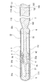
図1は、本発明のガイドワイヤの一実施例の部分省略正面図である。図2は、図1に示したガイドワイヤの部分省略断面図である。図3は、本発明のガイドワイヤに用いられるコイル固定用部材の一例の正面図である。図4は、図3に示したコイル固定用部材の右側面図である。図5は、本発明のガイドワイヤに用いられるコイル固定用部材の他の例の右側面図である。図6は、本発明のガイドワイヤに用いられるコイル固定用部材の他の断面図である。図7ないし図9は、本発明のガイドワイヤに用いられるコイル固定用部材の他の例の正面図である。
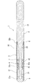
本発明のガイドワイヤ1は、芯材2と、芯材2の少なくとも先端側部分を被包するコイル3とを備える。ガイドワイヤ1は、芯材2の先端側部分に固定されるとともに、コイル3の長手方向の少なくとも一部分にて、コイル3を芯材2に対してほぼ同心状となるよう固定するためのコイル固定用部材4を備え、コイル2は、コイル固定用部材4に接着用材料を介して固定されている。
The guide wire of the present invention will be described using an embodiment shown in the drawings.
FIG. 1 is a partially omitted front view of an embodiment of a guide wire according to the present invention. FIG. 2 is a partially omitted sectional view of the guide wire shown in FIG. FIG. 3 is a front view of an example of a coil fixing member used in the guide wire of the present invention. 4 is a right side view of the coil fixing member shown in FIG. FIG. 5 is a right side view of another example of a coil fixing member used for the guide wire of the present invention. FIG. 6 is another cross-sectional view of a coil fixing member used in the guide wire of the present invention. 7 to 9 are front views of other examples of the coil fixing member used in the guide wire of the present invention.
The guide wire 1 of the present invention includes a
図1および図2に示す実施例のガイドワイヤ1は、芯材2と、芯材2の少なくとも先端側部分を被包するコイル3とを備える。コイル3は、先端側コイル31と基端側コイル32とを備える。そして、図2に示すように、コイル固定用部材4は、先端側コイル31の基端部31bおよび基端側コイル32の先端部32aを芯材2に固定するためのものである。コイル3の先端、この実施例では、先端側コイル31の先端31aは、芯材2の先端部に固定されている。コイル3の基端、この実施例では、基端側コイル32の基端32bは、芯材2の先端より所定距離基端側となる部分に固定されている。つまり、この実施例のガイドワイヤ1では、コイル3は、先端が芯材2の先端に固定されており、コイル3の基端は、芯材2の先端より所定距離基端側となる部分に固定されており、芯材2は、コイル3の基端部より延出しガイドワイヤ1の本体部分を構成している。
The guide wire 1 of the embodiment shown in FIGS. 1 and 2 includes a
ガイドワイヤ1の全長は、300〜4500mm程度が好ましく、1000〜2000mm程度が特に好ましい。
芯材2は、基端側より、本体部22、テーパー部23および先端部21を有する。本体部22は、芯材2の基端より、先端側に向かって延びるほぼ一定外径を有する長尺な部分であり、先端部21は、本体部22に比べて小径となっている。この実施例では、先端部21は、略同一径にて先端側に延びるものとなっている。そして、先端部21と本体部22間にテーパー部23が形成されている。
本体部22におけるガイドワイヤ1の外径は、0.2〜1.8mm、好ましくは0.3〜1.6mm程度が特に好ましい。また、先端部21の外径としては、0.05mm〜1.6mm、長さは10mm〜500mm、好ましくは20mm〜300mmである。先端部21は、先端側がより柔軟となるものであってもよく、例えば、熱処理により先端に向かって徐々に柔軟なものとしてもよい。
The total length of the guide wire 1 is preferably about 300 to 4500 mm, and particularly preferably about 1000 to 2000 mm.
The
The outer diameter of the guide wire 1 in the
芯材2の構成材料としては、例えば、Ni−Ti合金等の超弾性合金、ステンレス鋼、ピアノ線等の各種金属材料などが用いられる。
コイル3としては、全長が10mm〜500mm、好ましくは20mm〜300mmであり、コイル3の外径としては、直径0.2〜1.8mm、好ましくは、0.3〜1.6mmである。そして、コイル3は、芯材2の先端部21およびテーパー部23を被包している。コイルの先端は芯材2の先端に固定されており、コイルの基端は、芯材2のテーパー部の基端部にロウ6等で固着されている。
この実施例では、コイル3は、図1および図2に示すように、先端側コイル31と基端側コイル32とにより構成されている。さらに、先端側コイル31の基端部31bと基端側コイル32の先端部32aは絡み合っている。このように両者が絡み合うことにより、両者が離間するすることを防止する。両者の絡み合う距離としては、0.1〜2mm程度が好適である。
As a constituent material of the
The
In this embodiment, the
また、先端側コイル31と基端側コイル32とは物性が異なることが好ましい。両者の物性は、ガイドワイヤの目的に応じて種々選択可能である。例えば、基端側コイルに比べて先端側コイルは柔軟なものとすること(コイル柔軟性は、例えば、コイルの素線に一定の隙間を設けるか、素線を密着させて巻くかによって変えること、コイルの素線径を変えること、コイルの素材を変えることなどにより変化させることができる)、また、基端側コイルに比べて先端側コイルは造影性が高いものとすることなどが考えられる。この実施例では、先端側コイル31の素線径は、基端側コイルの素線径より太いものがものが用いられている。なお、先端側コイル31および基端側コイル32は、ほぼ同じ外径となっている。先端側コイルの長さとしては、3〜60mm程度が好適であり、基端側コイルの長さとしては、10〜40mm程度が好適である。また、先端側コイル31の内径は、基端側コイル32の内径より小さいものとなっている。
The physical properties of the distal
コイルの形成材料としては、例えば、Ni−Ti合金等の超弾性合金、ステンレス鋼、金、白金などの貴金属などが使用できる。そして、先端側コイルおよび基端側コイルは、同じ材料により形成すること、また異なる材料により形成することのいずれでもよい。異なる材料を用いる場合には、例えば、先端側コイルとしては、金、白金などの貴金属を用い、基端側コイルとしては、ステンレス鋼を用いること、また、先端側コイルとしては、超弾性合金を用い、基端側コイルとしては、ステンレス鋼を用いることなどが考えられる。
そして、コイル3の先端は、芯材2の先端にロウ5により固定されている。そして、ロウ5により形成されるガイドワイヤ1の先端は、半球状先端部となっている。半球状先端とは、実質的に曲面に成形されていることを意味し、例えば釣鐘状、弾丸状などの形状を含むものである。
As a material for forming the coil, for example, a superelastic alloy such as a Ni—Ti alloy, a noble metal such as stainless steel, gold, or platinum can be used. The distal end side coil and the proximal end side coil may be formed of the same material or formed of different materials. When using different materials, for example, a noble metal such as gold or platinum is used as the distal end side coil, stainless steel is used as the proximal end side coil, and a super elastic alloy is used as the distal end side coil. It is conceivable to use stainless steel as the proximal end side coil.
The tip of the
そして、芯材2の先端部分には、コイル固定用部材4が固定されている。固定用部材4の芯材2への固定は、嵌合、ロウ付けなどどのような方法により行なってもよい。この固定用部材4は、コイル3の長手方向の少なくとも一部分にて、コイル3を芯材2に対してほぼ同心状となるよう固定するためのものである。固定用部材の長さとしては、0.2〜1.0mm程度が好適である。
コイル3における固定用部材4の位置は、本実施例では、コイル3の長手方向の中間部分よりも先端側に設けているが、コイル3の長手方向のほぼ中間部分や、コイル3の長手方向の中間部分よりも基端側に設けてもよい。コイル3における固定用部材4の位置は、コイル3の先端または基端より所定距離離間した位置となる。また、固定用部材4は複数設けてもよい。例えば、先端側コイル31と基端側コイル32を接合した部分から所定距離離れた先端側と基端側に固定用部材4を配置して、先端側コイル31と先端側固定用部材、基端側コイル32と基端側固定用部材をそれぞれロウなどの接着用材料を介して固定してもよい。
A
In the present embodiment, the position of the fixing
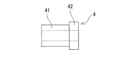
この実施例のガイドワイヤ1では、固定用部材は、図2ないし図4に示すように、筒状部材となっている。さらに、この固定用部材4は、先端側コイル3の基端部、図示する実施例では、先端側コイルと基端側コイルとの絡合部分に対応する小径部41と、基端側コイルに対応する大径部42とを備えている。このガイドワイヤ1では、固定用部材4は、先端側コイル31と基端側コイル32の絡合部分となる位置に設けられる。そして、固定用部材4の小径部41の外径は、先端側コイル31の内径より若干小さいものとなっている。同様に、固定用部材4の大径部42の外径は、基端側コイル32の内径より若干小さいものとなっている。また、固定用部材4の大径部42の外径は、先端側コイル31の内径より若干大きいものであることが好ましい。このようにすることにより、図2に示すように、先端側コイル31の後端は、固定用部材4の大径部の端部に当接するため、先端側コイルの移動を防止できる。さらに、芯材へのコイルの固定作業も容易なものとなる。また、この実施例における固定用部材4では、大径部42の軸方向の長さが、小径部41の軸方向の長さよりも短いものとなっている。
In the guide wire 1 of this embodiment, the fixing member is a cylindrical member as shown in FIGS. Further, the fixing
そして、コイル3は、コイル固定用部材4に接着用材料であるロウ7により固定されている。接着用材料は、前述したロウ(ハンダを含む)の他に、樹脂製接着剤が挙げられる。コイル3は、コイル固定用部材4に接着用材料を介して固定されている。接着用材料は、固定用部材4と芯材2の間に充填されている。
このような固定用部材4を設けることにより、芯材(固定用部材)とコイル間の空隙が減少するために、コイル3を芯材に対して、ほぼ同心状となるよう固定することができ、生体内挿入時に、ガイドワイヤの先端部は、偏りのない良好な変形を生じるとともにスムーズなトルク伝達性を実現できるものとなる。また、固定時にロウがガイドワイヤの軸方向に過剰に流れることがなくなり、コイルと芯材との固定部の長さを短いものとできる。
コイル固定用部材の材料としては、銀ロウ等のロウ材、ロウ(ハンダ)になじみやすい金、銅などの貴金属、ステンレス鋼などの金属材料のほか、プラスチックでもよい。コイル固定用部材をプラスチックにて構成した場合は、接着用材料として樹脂用接着剤が好適である。
The
By providing such a fixing
As a material for the coil fixing member, a brazing material such as silver brazing, a gold that is easily compatible with brazing (solder), a noble metal such as copper, a metal material such as stainless steel, or a plastic may be used. When the coil fixing member is made of plastic, a resin adhesive is suitable as an adhesive material.
コイル固定用部材としては、上述した実施例のものに限定されるものではなく、例えば、図5に示す固定用部材4aのように、内腔の内壁に軸方向に延びる溝43を備えるものであってもよい。溝43は、図示するように、複数設けることが好ましい。このような溝を設けることにより、固定用部材と芯材間へのロウの流入を容易なものとできる。また、図6に示す固定用部材4bのように、大径部41部分の内腔が、他の部分に比べて拡径した部分44となっているものであってもよい。この拡径部分44を設けることにより、固定用部材と芯材間へのロウの流入を容易なものとできる。また、図7に示す固定用部材4cのように、軸方向に延びるスリット45を備えるものであってもよい。スリット45は、図示するように、複数設けることが好ましい。また、図示するものでは、スリット45は、固定用部材の一端から他端まで連通しないものとなっている。このようなスリットを設けることにより、固定用部材と芯材間へのロウの流入さらには固定用部材とコイル間へのロウの流入を容易なものとできる。また、図8に示す固定用部材4dのように、網状体、さらには、図9に示す固定用部材4eのように、コイル状部材であってよい。このようなものでも、固定用部材と芯材間へのロウの流入さらには固定用部材とコイル間へのロウの流入を容易なものとできる。
また、固定用部材は芯材の全周を覆うものが好ましいが、例えば、軸方向にスリットを有するような芯材を一部分覆わないものであってもよい。さらに、固定用部材は、その横断面において複数の部材からなるものでもよい。例えば、芯材の周囲を二つ以上の部材で少なくとも一カ所の非被覆部分を有して覆うものであってもよい。
The coil fixing member is not limited to the above-described embodiment, and includes a
In addition, the fixing member preferably covers the entire circumference of the core material. For example, the fixing member may not partially cover the core material having a slit in the axial direction. Further, the fixing member may be composed of a plurality of members in its cross section. For example, the core material may be covered with at least one uncovered portion with two or more members.
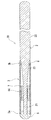
次に、図10に示す実施例のガイドワイヤ10について説明する。
このガイドワイヤ10と上述したガイドワイヤ1との基本構成は、同じである。相違点は、芯材の先端部の形態とコイル固定用部材の内腔の形態のみである。よって、相違点のみ説明し、他の部分については、上述した説明を参照する。
芯材2は、基端側より、本体部52、テーパー状中間部53およびテーパー状先端部51を有する。本体部52は、芯材2の基端より、先端側に向かって延びるほぼ一定外径を有する長尺な部分である。テーパー状先端部51は、本体部52に比べて小径となっているとともに、先端側に向かって緩やかに小径となっている。そして、テーパー状先端部51と本体部52間にテーパー状中間部53が形成されている。このテーパー状中間部53は、テーパー状先端部より、外径が大きく変化するテーパーとなっている。このようにすることにより、先端部51を先端側がより柔軟となるものとすることができる。なお、テーパー状先端部51は、全体がテーパー状になっているものに限定されるものではなく、部分的にストレート部分を備えるものであってもよい。
Next, the
The basic configuration of the
The
この実施例のガイドワイヤ10では、固定用部材は、図10に示すように、筒状部材となっている。また、この固定用部材54は、内腔が芯材の先端部のテーパー形状に合わせて先端に向かって縮径している。このため、芯材2にこの固定用部材54を装着したとき、固定用部材54ががたつくことが少なく、固定用部材自体を芯材に対して同心状に容易に配置できる。また、この固定用部材54は、上述した固定用部材4と同様に、先端側コイルと基端側コイルとの絡合部分に対応する小径部54aと、基端側コイルに対応する大径部54bとを備えている。このガイドワイヤ10においても、固定用部材54は、先端側コイル31と基端側コイル32の絡合部分となる位置に設けられる。そして、固定用部材54の小径部54aの外径は、先端側コイル31の内径より若干小さいものとなっている。同様に、固定用部材54の大径部54bの外径は、基端側コイル32の内径より若干小さいものとなっている。また、固定用部材54の大径部54bの外径は、先端側コイル31の内径より若干大きいものであることが好ましい。このようにすることにより、図10に示すように、先端側コイル31の後端は、固定用部材54の大径部の端部に当接する。コイル3は、コイル固定用部材54にロウ7により固定されている。このような固定用部材54を設けることにより、芯材(固定用部材)とコイル間の空隙が減少するために、コイル3を芯材に対して、ほぼ同心状となるよう固定することができ、生体内挿入時に、ガイドワイヤの先端部は、偏りのない良好な変形を生じるものとなる。
In the
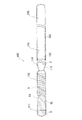
次に、図11に示す実施例のガイドワイヤ20について説明する。
このガイドワイヤ20と上述したガイドワイヤ1との基本構成は、同じである。相違点は、コイル3を構成する先端側コイル31の基端部31bと基端側コイル32の先端部32aが絡み合っていない点のみである。よって、相違点のみ説明し、他の部分については、上述した説明を参照する。
先端側コイル31の基端部31bと基端側コイル32の先端部32aが絡み合っていないため、コイル固定用部材4は、先端側コイル31の基端部31bと基端側コイル32の先端部32aを芯材2に固定するものとなる。よって、固定用部材4は、先端側コイルおよび基端側コイルの両者を個々に芯材に対して、ほぼ同心状となるよう固定するように機能する。そして、固定用部材4は、小径部41と大径部42を備え、小径部41の外径は、先端側コイル31の内径より若干小さいものとなっている。同様に、固定用部材4の大径部42の外径は、基端側コイル32の内径より若干小さいものとなっている。また、固定用部材4の大径部42の外径は、先端側コイル31の内径より若干大きいものとなっている。このようにすることにより、図11に示すように、先端側コイル31の後端は、固定用部材4の大径部の端部に当接する。コイル3は、コイル固定用部材4にロウ7により固定されている。このような固定用部材4を設けることにより、芯材(固定用部材)とコイル間の空隙が減少するために、コイル3を芯材に対して、ほぼ同心状となるよう固定することができ、生体内挿入時に、ガイドワイヤの先端部は、偏りのない良好な変形を生じるものとなる。
Next, the
The basic configurations of the
Since the
次に、図12に示す実施例のガイドワイヤ30について説明する。
このガイドワイヤ30と上述したガイドワイヤ1との基本構成は、同じである。相違点は、コイル3として単体のコイルを用いている点およびコイル固定用部材の形態のみである。よって、相違点のみ説明し、他の部分については、上述した説明を参照する。
コイル3としては、図12に示すように、全体が同じ素線により形成されたものとなっており、全体がほぼ同一の外径および同一の内径を備えるものとなっている。そして、コイル固定用部材64は、図12に示すように、ほぼ同一外径を備える筒状部材となっている。この固定用部材64を用いることにより、コイルの中間部分を芯材に対して、ほぼ同心状となるよう固定することができる。固定用部材64の外径は、コイル3の内径より若干小さいものとなっている。コイル3は、コイル固定用部材64にロウ7により固定されている。このような固定用部材64を設けることにより、芯材(固定用部材)とコイル間の空隙が減少するために、コイル3を芯材に対して、ほぼ同心状となるよう固定することができ、生体内挿入時に、ガイドワイヤの先端部は、偏りのない良好な変形を生じるものとなる。
Next, the
The basic configurations of the
As shown in FIG. 12, the
なお、単体のコイルとしては、全て同一の材料からなるものの他に、先端側の素線を白金などの造影性材料にて形成し、基端側の素線をステンレス鋼などの先端側より造影性の低い材料にて形成し、先端側素線の基端部と基端側素線の先端部を接合して一体的にコイルにしたものも含む。この場合、固定用部材64は、素線の接合部に上述のように芯材とコイルの間に介在してもよいが、接合部を挟んで先端側および/または基端側に位置してもよい。
In addition, as a single coil, in addition to those made of the same material, the wire on the distal end side is formed of a contrasting material such as platinum, and the wire on the proximal end is contrasted from the distal end side such as stainless steel. It includes a material that is formed of a low-performance material, and that integrally joins the proximal end of the distal end side strand and the distal end of the proximal end strand to form a coil. In this case, the fixing
また、図13に示すガイドワイヤ40のように、コイル固定用部材64aは、側面に軸方向に延びる溝もしくは環状の溝を備えるものであってもよい。このようにすることにより、コイル3と固定用部材64a間へのロウの流入が容易となる。
図12、13の実施例において、コイル固定用部材64aに位置するコイル3に隙間を設けることによって隙間よりロウ(ハンダ)を溶かし込み易くできる。
なお、上述した実施例のガイドワイヤ20および30においても、上述したガイドワイヤ10のような芯材の先端部の形態とコイル固定用部材の内腔の形態を備えるものとしてもよい。
Moreover, like the
In the embodiment of FIGS. 12 and 13, it can be easily narrowing dissolved wax (solder) than the gap by providing a gap in the
Note that the
次に、図14に示す実施例のガイドワイヤ70について説明する。
このガイドワイヤ70と上述したガイドワイヤ1との基本構成は、同じである。相違点は、芯材の形態とコイルの形態のみである。よって、相違点のみ説明し、他の部分については、上述した説明を参照する。
コイル3は、芯材72の全体を被包している。芯材72は、基端側より先端側まで、ほぼ同じ外径を備えるものなっている。なお、芯材72の先端部は、上述したガイドワイヤ10のように先端に向かって縮径するものであってもよい。
コイル3は、先端側コイル76と基端側コイル77を備えている。先端側コイル76は、上述した先端側コイル31と同じである。基端側コイル77は、その後端77bが芯材72の後端まで延び、芯材72の後端に固定されている。この実施例のガイドワイヤ70においても、上述した固定用部材4と同様に、先端側コイル76の基端部76bと基端側コイル77の先端部77aとは絡み合っている。固定用部材74は、先端側コイル76と基端側コイル77との絡合部分に対応する小径部74aと、基端側コイル77に対応する大径部74bとを備えている。このガイドワイヤ70においても、固定用部材74は、先端側コイル76と基端側コイル77の絡合部分となる位置に設けられる。
Next, the
The basic configurations of the
The
The
そして、固定用部材74の小径部74aの外径は、先端側コイル76の内径より若干小さいものとなっている。同様に、固定用部材74の大径部74bの外径は、基端側コイル77の内径より若干小さいものとなっている。また、固定用部材74の大径部74aの外径は、先端側コイル76の内径より若干大きいものであることが好ましい。このようにすることにより、図14に示すように、先端側コイル76の後端は、固定用部材74の大径部の端部に当接する。
コイル3は、コイル固定用部材74にロウ7により固定されている。そして、コイル3の先端(先端側コイル76の先端76a)は、芯材72の先端にロウ5により固定されている。そして、ロウ5により形成されるガイドワイヤ70の先端は、半球状先端部となっている。半球状先端とは、実質的に曲面に成形されていることを意味し、例えば釣鐘状、弾丸状などの形状を含むものである。
上述したように、固定用部材74を設けることにより、芯材(固定用部材)とコイル間の空隙が減少するために、コイル3を芯材に対して、ほぼ同心状となるよう固定することができ、生体内挿入時に、ガイドワイヤの先端部は、偏りのない良好な変形を生じるものとなる。
The outer diameter of the
The
As described above, since the gap between the core material (fixing member) and the coil is reduced by providing the fixing
次に、図15に示す実施例のガイドワイヤ80について説明する。
図15は、本発明の他の実施例のガイドワイヤの断面図である。図16は、本発明のガイドワイヤに使用される筒状部材の他の例の外観図である。
このガイドワイヤ80と上述したガイドワイヤ1との基本構成は、同じである。
相違点は、コイル固定用部材の形態のみである。よって、相違点を中心に説明し、他の部分については、上述した説明を参照する。
この実施例のガイドワイヤ80においてもガイドワイヤ1と同様に、固定用部材81は、図15および図16に示すように、筒状部材となっている。固定用部材81は、図16に示すように外面に、コイルの内側部分の形状に対応した螺旋状の溝84を備えている。そして、図15に示すように、先端側コイル31の基端部の内側部分は、固定用部材81の溝84内に入り込んだ状態となっている。 この実施例のガイドワイヤ80では、先端側コイル31の基端部31bと基端側コイル32の先端部32aが絡み合っている。これを考慮して、固定用部材81の溝84は、ピッチが広いものとなっている。
Next, the
FIG. 15 is a cross-sectional view of a guide wire according to another embodiment of the present invention. FIG. 16 is an external view of another example of a cylindrical member used in the guide wire of the present invention.
The basic configurations of the
The only difference is the form of the coil fixing member. Therefore, it demonstrates centering around difference and the description mentioned above is referred about another part.
Also in the
そして、この固定用部材81は、図16に示すように、先端側コイル31の基端部、図示する実施例では、先端側コイルと基端側コイルとの絡合部分に対応する小径部82と、基端側コイルに対応する大径部83とを備えている。
また、このガイドワイヤ80では、上述したガイドワイヤ1と同様に、固定用部材81は、先端側コイル31と基端側コイル32の絡合部分となる位置に設けられる。そして、固定用部材81の小径部82の外径は、先端側コイル31の内径より若干大きいものとなっている。なお、先端側コイル31の固定用部材81の小径部上となる部分は、上述した溝84内に入り込むため、先端側コイル31の固定用部材81上となる部分は、他の部分と同じ外径を維持している。また、固定用部材81の大径部83の外径は、基端側コイル32の内径より若干小さいものとなっている。また、固定用部材81の大径部83の外径は、先端側コイル31の内径より若干大きいものであることが好ましい。このようにすることにより、先端側コイル31の後端は、固定用部材81の大径部の端部に当接するため、先端側コイルの移動を防止できる。さらに、芯材へのコイルの固定作業も容易なものとなる。
As shown in FIG. 16, the fixing
Further, in this
そして、コイル3は、コイル固定用部材81に接着用材料であるロウ7により固定されている。接着用材料は、前述したロウ(ハンダを含む)の他に、樹脂製接着剤が挙げられる。コイル3は、コイル固定用部材81に接着用材料を介して固定されている。接着用材料は、固定用部材81と芯材2の間に充填されている。
このような固定用部材81を設けることにより、芯材(固定用部材)とコイル間の空隙が減少するために、コイル3を芯材に対して、ほぼ同心状となるよう固定することができ、生体内挿入時に、ガイドワイヤの先端部は、偏りのない良好な変形を生じるとともにスムーズなトルク伝達性を実現できるものとなる。また、固定時にロウがガイドワイヤの軸方向に過剰に流れることがなくなり、コイルと芯材との固定部の長さを短いものとできる。
The
By providing such a fixing
また、この実施例のガイドワイヤにおけるコイル固定用部材としては、上述したものに限定されるものではなく、例えば、図5に示した固定用部材4aのように、内腔の内壁に軸方向に延びる溝43を備えるものであってもよい。溝43は、図示するように、複数設けることが好ましい。このような溝を設けることにより、固定用部材と芯材間へのロウの流入を容易なものとできる。また、図6に示した固定用部材4bのように、大径部41部分の内腔が、他の部分に比べて拡径した部分44となっているものであってもよい。この拡径部分44を設けることにより、固定用部材と芯材間へのロウの流入を容易なものとできる。また、図7に示した固定用部材4cのように、軸方向に延びるスリット45を備えるものであってもよい。スリット45は、図示するように、複数設けることが好ましい。また、図示するものでは、スリット45は、固定用部材の一端から他端まで連通しないものとなっている。このようなスリットを設けることにより、固定用部材と芯材間へのロウの流入さらには固定用部材とコイル間へのロウの流入を容易なものとできる。
また、この実施例のガイドワイヤ80においても、上述したガイドワイヤ10のような芯材の先端部の形態とコイル固定用部材の内腔の形態を備えるものとしてもよい。
Further, the coil fixing member in the guide wire of this embodiment is not limited to the above-described one, and for example, as in the fixing
Further, the
さらに、この実施例のガイドワイヤにおけるコイルは、上述したものに限定されるものではなく、図11に示したガイドワイヤ20のように、コイル3として、先端側コイル31の基端部31bと基端側コイル32の先端部32aが絡み合っていないものであってもよい。この場合、固定用部材81に設けられる溝84は、先端側コイルの基端部が基端側コイルにより押し広がられないため、言い換えれば、先端側コイル31の基端のピッチが、図15に示すものより短いものとなるため、ピッチは短い(先端側コイルの全体のピッチと同じ)ものとなる。
Further, the coil in the guide wire of this embodiment is not limited to the above-described one, and as the
さらに、この実施例のガイドワイヤにおけるコイルとして、図12に示したガイドワイヤ30のように、単体のコイル3を用いるものであってもよい。この場合、コイル3としては、図12に示すように、全体が同じ素線により形成されたものとなり、全体がほぼ同一の外径および同一の内径を備えるものとなる。そして、この場合におけるコイル固定用部材は、図12に示すもののように、ほぼ同一外径を備える筒状部材となる。そして、固定用部材の外面全体に、コイルのピッチと同じピッチの螺旋状の溝を備えるものとなる。
なお、単体のコイルとしては、全て同一の材料からなるものの他に、先端側の素線を白金などの造影性材料にて形成し、基端側の素線をステンレス鋼などの先端側より造影性の低い材料にて形成し、先端側素線の基端部と基端側素線の先端部を接合して一体的にコイルにしたものも含む。この場合、固定用部材は、素線の接合部に上述のように芯材とコイルの間に介在してもよいが、接合部を挟んで先端側および/または基端側に位置してもよい。
さらに、この実施例のガイドワイヤにおいても、図14に示したガイドワイヤ70と同様の芯材の形態およびコイルの形態を有するものであってもよい。
Furthermore, as a coil in the guide wire of this embodiment, a
In addition, as a single coil, in addition to those made of the same material, the wire on the distal end side is formed of a contrasting material such as platinum, and the wire on the proximal end is contrasted from the distal end side such as stainless steel. It includes a material that is formed of a low-performance material, and that integrally joins the proximal end of the distal end side strand and the distal end of the proximal end strand to form a coil. In this case, the fixing member may be interposed between the core material and the coil as described above in the joint portion of the strands, but may be located on the distal end side and / or the proximal end side with the joint portion interposed therebetween. Good.
Furthermore, the guide wire of this embodiment may have the same core material form and coil form as the
本発明の他の実施例のガイドワイヤを図面に示す実施例を用いて説明する。
図17は、本発明のガイドワイヤの他の実施例の部分省略正面図である。図18は、図17に示したガイドワイヤのA−A線断面図である。
この実施例のガイドワイヤ90は、芯材2と、芯材2の少なくとも先端側部分を被包するコイル3とを備える。ガイドワイヤ90は、芯材2の先端側部分に固定されるとともに、コイル3の長手方向の少なくとも一部分にて、コイル3を芯材2に対してほぼ同心状となるよう固定するためのコイル固定用部材4を備え、コイル2は、コイル固定用部材4に溶接により固定されている。
この実施例のガイドワイヤ90では、コイル3は、コイル固定用部材4に溶接により固定されている。溶接方法としては、レーザ溶接、アーク溶接、抵抗溶接などの公知の方法が使用できる。この実施例のガイドワイヤ90では、スポット溶接により固定されており、2つの固定部8a,8bを有している。そして、一方の固定部8aは、固定用部材4の中央部もしくは中央部より基端側に位置し、他方の固定部8bは、固定用部材4の先端側に位置している。さらに、この実施例のガイドワイヤ90では、コイル3は、図17および図18に示すように、先端側コイル31と基端側コイル32とにより構成されており、さらに、先端側コイル31の基端部31bと基端側コイル32の先端部32aは絡み合っている。そして、一方の固定部8aは、コイルの絡み合っている部分の基端部を固定用部材に固定しており、他方の固定部8bは、コイルの絡み合っている部分の先端部を固定用部材4に固定している。
A guide wire according to another embodiment of the present invention will be described with reference to an embodiment shown in the drawings.
FIG. 17 is a partially omitted front view of another embodiment of the guide wire according to the present invention. 18 is a cross-sectional view taken along line AA of the guide wire shown in FIG.
The
In the
固定部8a及び8bは、先端側コイル31、基端側コイル32及び固定用部材4の少なくとも表面が互いに溶融し固化した部分であることが好ましい。溶融固化部は、まず、レーザ溶接など前述の溶接方法によるエネルギー照射によって、先端側コイル31及び基端側コイル32が溶融し、更に固定用部材4の表面も溶融し、さらに、溶融したコイル31、32及び固定用部材4の表面形成材料が互いに混じりあった状態で固化したものとなっている。このようにして溶融固化部は互いの材料が混合して固化するのでコイルと固定用部材が強固に固定された固定部を形成する。
固定用部材の材料としては、銀ロウ等のロウ材、ロウ(ハンダ)になじみやすい金、銅などの貴金属、ステンレス鋼などの金属材料が挙げられる。固定用部材を構成する材料の融点がコイルを構成する材料の融点よりも低いことが好ましい。すなわち、固定用部材の重量が固定部の面積に相当するコイルの重量より充分に大きいので、レーザ等のエネルギーで、コイル及び固定用部材表面は溶融するが、固定用部材全体は溶融せず形を維持できる。コイルを構成する材料の融点よりも低い材料にて固定用部材を構成するほかに、固定用部材の少なくとも表面を、コイルを構成する材料の融点よりも低い材料にて形成することも可能である。コイルが異なる融点を有する材料からなる二層構造(例えば、外層をX線造影性の低いステンレス鋼、内層をX線造影性の高い白金)を有する場合は、個々の材料の融点と断面積占有率から計算してコイルの融点とすることができる。
The fixing
Examples of the material for the fixing member include a brazing material such as silver brazing, gold, copper, a precious metal such as copper, and a metal material such as stainless steel. The melting point of the material constituting the fixing member is preferably lower than the melting point of the material constituting the coil. That is, since the weight of the fixing member is sufficiently larger than the weight of the coil corresponding to the area of the fixing portion, the surface of the coil and the fixing member is melted by energy such as laser, but the entire fixing member is not melted. Can be maintained. In addition to constituting the fixing member with a material lower than the melting point of the material constituting the coil, it is also possible to form at least the surface of the fixing member with a material lower than the melting point of the material constituting the coil. . If the coil has a two-layer structure of materials with different melting points (for example, the outer layer is stainless steel with low X-ray contrast properties and the inner layer is platinum with high X-ray contrast properties), the melting point and cross-sectional area occupation of each material The melting point of the coil can be calculated from the rate.
この実施例では、2つの固定部8a,8bは、所定長ガイドワイヤの軸方向に離間している。また、この実施例では、2つの固定部8a,8bは、ガイドワイヤの中心軸に対してほぼ180度ずれた位置となるように設けられている。
固定部の位置としては、一方の固定部8aがコイルの絡み合っている部分よりも先端側の先端側コイル及び固定用部材に位置し、他方の固定部8bがコイルの絡み合っている部分よりも基端側の基端側コイル及び固定用部材に位置する例が挙げられる。
なお、このように点状に溶接して固定部を形成する場合、固定部の数としては、上記の2つに限定されるものではなく、3以上であってもよい。また、3以上の固定部を設ける場合には、それぞれの固定部は、ガイドワイヤの中心軸に対して、ほぼ等角度となるように設けることが好ましい。さらに、3以上の固定部を設ける場合には、それぞれの固定部は、ガイドワイヤの軸方向に対して、ほぼ等間隔となるように設けることが好ましい。また、固定部は、上記のように点状に形成されるものに限定されるものではなく、環状に溶接するものであってもよい。
そして、上述したすべての実施例のガイドワイヤにおいて、コイルはコイル固定用部材に溶接により固定するものとしてもよい。溶接による固定部としては、上述したものが好適である。
In this embodiment, the two fixing
As for the position of the fixing portion, one fixing
In addition, when forming a fixing | fixed part by welding in dot shape in this way, as a number of fixing | fixed parts, it is not limited to said two, Three or more may be sufficient. When three or more fixing portions are provided, each fixing portion is preferably provided so as to be substantially equiangular with respect to the central axis of the guide wire. Further, when three or more fixing parts are provided, it is preferable that the fixing parts are provided at substantially equal intervals in the axial direction of the guide wire. Moreover, a fixing | fixed part is not limited to what is formed in dot shape as mentioned above, You may weld cyclically | annularly.
And in the guide wire of all the embodiments described above, the coil may be fixed to the coil fixing member by welding. As the fixing portion by welding, those described above are suitable.
ガイドワイヤ90は、図17および図18に示すように、芯材2と、芯材2の少なくとも先端側部分を被包するコイル3とを備える。コイル3は、先端側コイル31と基端側コイル32とを備える。そして、図18に示すように、コイル固定用部材4は、先端側コイル31の基端部31bおよび基端側コイル32の先端部32aを芯材2に固定するためのものである。コイル3の先端、この実施例では、先端側コイル31の先端31aは、芯材2の先端部に固定されている。コイル3の基端、この実施例では、基端側コイル32の基端32bは、芯材2の先端より所定距離基端側となる部分に固定されている。つまり、この実施例のガイドワイヤ90では、コイル3は、先端が芯材2の先端に固定されており、コイル3の基端は、芯材2の先端より所定距離基端側となる部分に固定されており、芯材2は、コイル3の基端部より延出しガイドワイヤ90の本体部分を構成している。
As shown in FIGS. 17 and 18, the
ガイドワイヤ90の全長は、300〜4500mm程度が好ましく、1000〜2000mm程度が特に好ましい。
芯材2は、基端側より、本体部22、テーパー部23および先端部21を有する。本体部22は、芯材2の基端より、先端側向かって延びるほぼ一定外径を有する長尺な部分であり、先端部21は、本体部22に比べて小径となっている。この実施例では、先端部21は、略同一径にて先端側に延びるものとなっている。そして、先端部21と本体部22間にテーパー部23が形成されている。
本体部22におけるガイドワイヤ90の外径は、0.2〜1.8mm、好ましくは0.3〜1.6mm程度が特に好ましい。また、先端部21の外径としては、0.05mm〜1.6mm、長さは10mm〜500mm、好ましくは20mm〜300mmである。先端部21は、先端側がより柔軟となるものであってもよく、例えば、熱処理により先端に向かって徐々に柔軟なものとしてもよい。
芯材2の構成材料としては、例えば、Ni−Ti合金等の超弾性合金、ステンレス鋼、ピアノ線等の各種金属材料などが用いられる。
コイル3としては、全長が10mm〜500mm、好ましくは20mm〜300mmであり、コイル3の外径としては、直径0.2〜1.8mm、好ましくは、0.3〜1.6mmである。そして、コイル3は、芯材2の先端部21およびテーパー部23を被包している。コイルの先端は芯材2の先端に固定されており、コイルの基端は、芯材2のテーパー部の基端部にロウ6等で固着されている。
The total length of the
The
The outer diameter of the
As a constituent material of the
The
この実施例では、コイル3は、図17および図18に示すように、先端側コイル31と基端側コイル32とにより構成されている。さらに、先端側コイル31の基端部31bと基端側コイル32の先端部32aは絡み合っている。このように両者が絡み合うことにより、両者が離間するすることを防止する。両者の絡み合う距離としては、0.1〜2mm程度が好適である。
また、先端側コイル31と基端側コイル32とは物性が異なることが好ましい。両者の物性は、ガイドワイヤの目的に応じて種々選択可能である。例えば、基端側コイルに比べて先端側コイルは柔軟なものとすること(コイル柔軟性は、例えば、コイルの素線に一定の隙間を設けるか、素線を密着させて巻くかによって変えること、コイルの素線径を変えること、コイルの素材を変えることなどにより変化させることができる)、また、基端側コイルに比べて先端側コイルは造影性が高いものとすることなどが考えられる。この実施例では、先端側コイル31の素線径は、基端側コイルの素線径より太いものがものが用いられている。さらに、先端側コイルの素線に一定の隙間を設けても良い。なお、先端側コイル31および基端側コイル32は、ほぼ同じ外径となっている。先端側コイルの長さとしては、3〜60mm程度が好適であり、基端側コイルの長さとしては、10〜40mm程度が好適である。また、先端側コイル31の内径は、基端側コイル32の内径より小さいものとなっている。
In this embodiment, the
The physical properties of the distal
コイルの形成材料としては、例えば、Ni−Ti合金等の超弾性合金、ステンレス鋼、金、白金などの貴金属などが使用できる。そして、先端側コイルおよび基端側コイルは、同じ材料により形成すること、また異なる材料により形成することのいずれでもよい。異なる材料を用いる場合には、例えば、先端側コイルとしては、金、白金などの貴金属を用い、基端側コイルとしては、ステンレス鋼を用いること、また、先端側コイルとしては、超弾性合金を用い、基端側コイルとしては、スレンレス鋼を用いることなどが考えられる。
そして、コイル3の先端は、芯材2の先端にロウ5により固定されている。そして、ロウ5により形成されるガイドワイヤ90の先端は、半球状先端部となっている。半球状先端とは、実質的に曲面に成形されていることを意味し、例えば釣鐘状、弾丸状などの形状を含むものである。
As a material for forming the coil, for example, a superelastic alloy such as a Ni—Ti alloy, a noble metal such as stainless steel, gold, or platinum can be used. The distal end side coil and the proximal end side coil may be formed of the same material or formed of different materials. When using different materials, for example, a noble metal such as gold or platinum is used as the distal end side coil, stainless steel is used as the proximal end side coil, and a super elastic alloy is used as the distal end side coil. It is conceivable to use stainless steel as the proximal coil.
The tip of the
そして、芯材2の先端部分には、コイル固定用部材4が固定されている。固定用部材4の芯材2への固定は、嵌合、ロウ付けなどどのような方法により行なってもよい。この固定用部材4は、コイル3の長手方向の少なくとも一部分にて、コイル3を芯材2に対してほぼ同心状となるよう固定するためのものである。固定用部材の長さとしては、0.2〜1.0mm程度が好適である。
コイル3における固定用部材4の位置は、本実施例では、コイル3の長手方向の中間部分よりも先端側に設けているが、コイル3の長手方向のほぼ中間部分や、コイル3の長手方向の中間部分よりも基端側に設けてもよい。コイル3における固定用部材4の位置は、コイル3の先端または基端より所定距離離間した位置となる。また、固定用部材4は複数設けてもよい。例えば、先端側コイル31と基端側コイル32を接合した部分から所定距離離れた先端側と基端側に固定用部材4を配置して、先端側コイル31と先端側固定用部材、基端側コイル32と基端側固定用部材をそれぞれロウなどの接着用材料を介して固定してもよい。
A
In the present embodiment, the position of the fixing
この実施例のガイドワイヤ90では、固定用部材は、図18に示すように、筒状部材となっている。さらに、この固定用部材4は、先端側コイル3の基端部、図示する実施例では、先端側コイルと基端側コイルとの絡合部分に対応する小径部41と、基端側コイルに対応する大径部42とを備えている。このガイドワイヤ90では、固定用部材4は、先端側コイル31と基端側コイル32の絡合部分となる位置に設けられる。そして、固定用部材4の小径部41の外径は、先端側コイル31の内径より若干小さいものとなっている。同様に、固定用部材4の大径部42の外径は、基端側コイル32の内径より若干小さいものとなっている。また、固定用部材4の大径部42の外径は、先端側コイル31の内径より若干大きいものであることが好ましい。このようにすることにより、図18に示すように、先端側コイル31の後端は、固定用部材4の大径部の端部に当接するため、先端側コイルの移動を防止できる。さらに、芯材へのコイルの固定作業も容易なものとなる。そして、この実施例における固定用部材4では、大径部42の軸方向の長さが小径部41の軸方向の長さよりも短くなっている。
In the
そして、この実施例のガイドワイヤ90では、コイル3は、コイル固定用部材4に溶接により固定されている。溶接方法としては、レーザ溶接、アーク溶接、抵抗溶接などの公知の方法が使用できる。レーザ溶接の場合、照射部位のスポット径を小さく調整することができ、さらに、照射部位の材料に応じて照射強度や時間を調整できるので好ましい。例えば融点の高い材料で形成されたコイルに対する照射強度は、融点の低い材料で形成されたコイルに対する照射強度よりも高くすることができる。
そして、このような固定用部材4を設けることにより、芯材(固定用部材)とコイル間の空隙が減少するために、コイル3を芯材に対して、ほぼ同心状となるよう固定することができ、生体内挿入時に、ガイドワイヤの先端部は、偏りのない良好な変形を生じるとともにスムーズなトルク伝達性を実現できるものとなる。また、固定時にロウがガイドワイヤの軸方向に過剰に流れることがなくなり、コイルと芯材との固定部の長さを短いものとできる。
In the
And by providing such a fixing
また、この実施例のガイドワイヤ90においても、コイル固定用部材としては、上述したものに限定されるものではなく、例えば、図5に示した固定用部材4aのように、内腔の内壁に軸方向に延びる溝43を備えるものであってもよい。溝43は、図示するように、複数設けることが好ましい。このような溝を設けることにより、固定用部材と芯材間へのロウの流入を容易なものとできる。また、図6に示した固定用部材4bのように、大径部41部分の内腔が、他の部分に比べて拡径した部分44となっているものであってもよい。この拡径部分44を設けることにより、固定用部材と芯材間へのロウの流入を容易なものとできる。また、図7に示した固定用部材4cのように、軸方向に延びるスリット45を備えるものであってもよい。スリット45は、図示するように、複数設けることが好ましい。また、図示するものでは、スリット45は、固定用部材の一端から他端まで連通しないものとなっている。このようなスリットを設けることにより、固定用部材と芯材間へのロウの流入さらには固定用部材とコイル間へのロウの流入を容易なものとできる。
Also, in the
また、この実施例のガイドワイヤ90においても、上述したガイドワイヤ10のような芯材の先端部の形態とコイル固定用部材の内腔の形態を備えるものとしてもよい。また、この実施例のガイドワイヤにおけるコイルとして、図12に示したガイドワイヤ30のように、単体のコイル3を用いるものであってもよい。
また、この実施例のガイドワイヤにおいても、図14に示したガイドワイヤ70と同様の芯材の形態およびコイルの形態を有するものであってもよい。さらに、この実施例のガイドワイヤ9においても、固定用部材は、図15および図16に示したもののように、固定用部材は、外面に、コイルの内側部分の形状に対応した螺旋状の溝を備え、図15に示すように、先端側コイル3の基端部の内側部分は、固定用部材の溝内に入り込んだ状態となっているものであってもよい。
Also, the
Also, the guide wire of this embodiment may have the same core form and coil form as the
そして、すべての実施例において、ガイドワイヤの外面の全面もしくは所望部分の外面には、カテーテル等の筒状体内面との摩擦抵抗を低下させるための潤滑性付与剤をコーティングしてもよい。
潤滑性付与剤としては、水溶性高分子物質またはその誘導体が好ましく、例えば、ポリ(2−ヒドロキシエチルメタクリレート)、ポリヒドロキシエチルアクリレート、セルロース系高分子物質(例えば、ヒドロキシプロピルセルロース、ヒドロキシエチルセルロース)、無水マレイン酸系高分子物質(例えば、メチルビニルエーテル無水マレイン酸共重合体)、アクリルアミド系高分子物質(例えば、ポリアクリルアミド)、ポリエチレンオキサイド系高分子物質(例えば、ポリエチレンオキサイド、ポリエチレングリコール)、ポリビニルアルコール、ポリアクリル酸系高分子物質(例えば、ポリアクリル酸ソーダ)、フタル酸系高分子物質(例えば、ポリヒドロキシエチルフタル酸エステル)、水溶性ポリエステル(例えば、ポリジメチロールプロピオン酸エステル)、ケトンアルデヒド樹脂(例えば、メチルイソプロピルケトンホルムアルデヒド)、ポリビニルピロリドン、ポリエチレンイミン、ポリスチレンスルホネート、水溶性ナイロンなどが使用できる。
In all of the embodiments, the entire outer surface of the guide wire or the outer surface of a desired portion may be coated with a lubricity imparting agent for reducing the frictional resistance with the inner surface of the tubular body such as a catheter.
As the lubricity imparting agent, a water-soluble polymer substance or a derivative thereof is preferable. For example, poly (2-hydroxyethyl methacrylate), polyhydroxyethyl acrylate, a cellulose-based polymer substance (for example, hydroxypropylcellulose, hydroxyethylcellulose), Maleic anhydride polymer (eg, methyl vinyl ether maleic anhydride copolymer), acrylamide polymer (eg, polyacrylamide), polyethylene oxide polymer (eg, polyethylene oxide, polyethylene glycol), polyvinyl alcohol Polyacrylic acid polymer materials (eg, polyacrylic acid soda), phthalic acid polymer materials (eg, polyhydroxyethyl phthalate), water-soluble polyesters (eg, polydimethyl ether) Propionic acid ester), a ketone aldehyde resin (e.g., methyl isopropyl ketone formaldehyde), polyvinyl pyrrolidone, polyethylene imine, polystyrene sulfonate, and water-soluble nylon can be used.
さらに、上述したすべての実施例のガイドワイヤにおいて、芯材2は、図19ないし図21に示すガイドワイヤ100に示すものであってもよい。また、上述したすべての実施例のガイドワイヤにおいて、ガイドワイヤは、図19ないし図21に示すガイドワイヤ100に示すように、表面被覆層を有するものであってもよい。図19は、本発明のガイドワイヤの他の実施例の部分省略正面図である。図20は、図19に示したガイドワイヤの部分省略断面図である。図21は、図19に示したガイドワイヤの先端部の拡大断面図である。
なお、この実施例のガイドワイヤの基本構成は、上述した実施例ガイドワイヤ90と同じものとなっているが、他の上述したすべての実施例のいずれかのガイドワイヤが備える構成であってもよい。同様に、固定部材としても、図5ないし図9および図16のいずれかのものを用いるものであってもよい。
ガイドワイヤ100では、芯材2は、先端側芯材102と基端側芯材103とからなる。先端側芯材102の基端が、基端側芯材103の先端に固定されている。
Furthermore, in the guide wires of all the embodiments described above, the
The basic configuration of the guide wire of this embodiment is the same as that of the above-described
In the
先端側芯材102は、弾性を有する線材である。先端側芯材102の長さは、特に限定されないが、20〜1000mm程度であるのが好ましい。この実施例のガイドワイヤ100では、先端側芯材102は、その基端から所定長さは外径が一定であり、途中から外径が先端方向へ向かって漸減している。
先端側芯材102の構成材料は、特に限定されず、例えば、ステンレス鋼などの各種金属材料を使用することができるが、そのなかでも特に、擬弾性を示す合金(超弾性合金を含む。)が好ましい。より好ましくは超弾性合金である。超弾性合金は、比較的柔軟であるとともに、復元性があり、曲がり癖が付き難い。先端側芯材102を超弾性合金で構成することにより、ガイドワイヤ100は、その先端側の部分に十分な柔軟性と曲げに対する復元性が得られる。このため、複雑に湾曲・屈曲する血管に対する追従性が向上し、より優れた操作性が得られる。さらに、先端側芯材102が湾曲・屈曲変形を繰り返しても、先端側芯材102に復元性により曲がり癖が付かないので、ガイドワイヤ100の使用中に先端側芯材102に曲がり癖が付くことによる操作性の低下を防止することができる。
The distal end
The constituent material of the front end
擬弾性合金には、引張りによる応力−ひずみ曲線のいずれの形状も含み、As、Af、Ms、Mf等の変態点が顕著に測定できるものも、できないものも含み、応力により大きく変形(歪)し、応力の除去により元の形状にほぼ戻るものは全て含まれる。
超弾性合金の好ましい組成としては、49〜52原子%NiのNi−Ti合金等のNi−Ti系合金、38.5〜41.5重量%ZnのCu−Zn合金、1〜10重量%XのCu−Zn−X合金(Xは、Be、Si、Sn、Al、Gaのうちの少なくとも1種)、36〜38原子%AlのNi−Al合金等が挙げられる。このなかでも特に好ましいものは、上記のNi−Ti系合金である。
先端側芯材102の基端には、基端側芯材103の先端が溶接により連結(接続)されている。基端側芯材103は、弾性を有する線材である。基端側芯材103の長さは、特に限定されないが、20〜4800mm程度であるのが好ましい。
Pseudoelastic alloys include any shape of stress-strain curve due to tension, including those that can measure the transformation point of As, Af, Ms, Mf, etc., and those that cannot be measured. However, everything that returns to its original shape by removing stress is included.
The preferred composition of the superelastic alloy is Ni-Ti alloy such as Ni-Ti alloy of 49-52 atomic% Ni, Cu-Zn alloy of 38.5-41.5 wt% Zn, 1-10 wt% X Cu-Zn-X alloy (X is at least one of Be, Si, Sn, Al, and Ga), 36-38 atomic% Al-Ni-Al alloy, and the like. Of these, the Ni-Ti alloy is particularly preferable.
The distal end of the proximal end
基端側芯材103は、先端側芯材102の構成材料より弾性率(ヤング率(縦弾性係数)、剛性率(横弾性係数)、体積弾性率)が大きい材料で構成されている。これにより、基端側芯材103に適度な剛性(曲げ剛性、ねじり剛性)が得られ、ガイドワイヤ100がいわゆるコシの強いものとなって押し込み性およびトルク伝達性が向上し、より優れた挿入操作性が得られる。
基端側芯材103の構成材料(素材)は、特に限定されず、ステンレス鋼(例えば、SUS304、SUS303、SUS316、SUS316L、SUS316J1、SUS316J1L、SUS405、SUS430、SUS434、SUS444、SUS429、SUS430F、SUS302等SUSの全品種)、ピアノ線、コバルト系合金、擬弾性合金などの各種金属材料を使用することができる。
この中でも、コバルト系合金は、ワイヤとしたときの弾性率が高く、かつ適度な弾性限度を有している。このため、コバルト系合金で構成された基端側芯材103は、特に優れたトルク伝達性を有し、座屈等の問題を極めて生じ難い。コバルト系合金としては、構成元素としてCoを含むものであれば、いかなるものを用いてもよいが、Coを主成分として含むもの(Co基合金:合金を構成する元素中で、Coの含有率が重量比で最も多い合金)が好ましく、Co−Ni−Cr系合金を用いるのがより好ましい。このような組成の合金を、基端側芯材103の構成材料として用いることにより、前述した効果がさらに顕著なものとなる。また、このような組成の合金は、弾性係数が高く、かつ高弾性限度としても冷間成形可能で、高弾性限度であることにより、座屈の発生を十分に防止しつつ、小径化することができ、所定部位に挿入するのに十分な柔軟性と剛性を備えるものとすることができる。
The proximal end
The constituent material (material) of the base end
Among these, the cobalt-based alloy has a high elastic modulus when used as a wire and has an appropriate elastic limit. For this reason, the base end
Co−Ni−Cr系合金としては、例えば、28〜50wt%Co−10〜30wt%Ni−10〜30wt%Cr−残部Feの組成からなる合金や、その一部が他の元素(置換元素)で置換された合金等が好ましい。置換元素の含有は、その種類に応じた固有の効果を発揮する。例えば、置換元素として、Ti、Nb、Ta、Be、Moから選択される少なくとも1種を含むことにより、基端側芯材103の強度のさらなる向上等を図ることができる。なお、Co、Ni、Cr以外の元素を含む場合、その(置換元素全体の)含有量は30wt%以下であるのが好ましい。
また、Co、Ni、Crの一部は、他の元素で置換してもよい。例えば、Niの一部をMnで置換してもよい。これにより、例えば、加工性のさらなる改善等を図ることができる。また、Crの一部をMoおよび/またはWで置換してもよい。これにより、弾性限度のさらなる改善等を図ることができる。Co−Ni−Cr系合金の中でも、Moを含む、Co−Ni−Cr−Mo系合金が特に好ましい。
Examples of the Co—Ni—Cr alloy include alloys having a composition of 28 to 50 wt% Co-10 to 30 wt% Ni-10 to 30 wt% Cr—remainder Fe, and a part of the other elements (substitution elements). Alloys substituted with are preferred. The inclusion of a substitution element exhibits a unique effect depending on the type. For example, by including at least one selected from Ti, Nb, Ta, Be, and Mo as a substitution element, the strength of the proximal
Further, a part of Co, Ni, and Cr may be substituted with other elements. For example, a part of Ni may be substituted with Mn. Thereby, the further improvement of workability etc. can be aimed at, for example. Further, a part of Cr may be replaced with Mo and / or W. Thereby, the further improvement of an elastic limit, etc. can be aimed at. Among Co—Ni—Cr alloys, Co—Ni—Cr—Mo alloys containing Mo are particularly preferable.
Co−Ni−Cr系合金の具体的な組成としては、例えば、[1]40wt%Co−22wt%Ni−25wt%Cr−2wt%Mn−0.17wt%C−0.03wt%Be−残部Fe、[2]40wt%Co−15wt%Ni−20wt%Cr−2wt%Mn−7wt%Mo−0.15wt%C−0.03wt%Be−残部Fe、[3]42wt%Co−13wt%Ni−20wt%Cr−1.6wt%Mn−2wt%Mo−2.8wt%W−0.2wt%C−0.04wt%Be−残部Fe、[4]45wt%Co−21wt%Ni−18wt%Cr−1wt%Mn−4wt%Mo−1wt%Ti−0.02wt%C−0.3wt%Be−残部Fe、[5]34wt%Co−21wt%Ni−14wt%Cr−0.5wt%Mn−6wt%Mo−2.5wt%Nb−0.5wt%Ta−残部Fe等が挙げられる。本発明でいうCo−Ni−Cr系合金とはこれらの合金を包含する概念である。 As a specific composition of the Co—Ni—Cr alloy, for example, [1] 40 wt% Co-22 wt% Ni-25 wt% Cr-2 wt% Mn—0.17 wt% C-0.03 wt% Be—balance Fe [2] 40 wt% Co-15 wt% Ni-20 wt% Cr-2 wt% Mn-7 wt% Mo-0.15 wt% C-0.03 wt% Be-balance Fe, [3] 42 wt% Co-13 wt% Ni- 20 wt% Cr-1.6 wt% Mn-2 wt% Mo-2.8 wt% W-0.2 wt% C-0.04 wt% Be-balance Fe, [4] 45 wt% Co-21 wt% Ni-18 wt% Cr- 1 wt% Mn-4 wt% Mo-1 wt% Ti-0.02 wt% C-0.3 wt% Be-balance Fe, [5] 34 wt% Co-21 wt% Ni-14 wt% Cr-0.5 wt% Mn-6 wt% Mo-2.5wt Nb-0.5wt% Ta- balance being Fe, and the like. The Co—Ni—Cr alloy referred to in the present invention is a concept that includes these alloys.
また、基端側芯材103の構成材料として、ステンレス鋼を用いた場合、ガイドワイヤ100は、より優れた押し込み性およびトルク伝達性が得られる。
また、先端側芯材102と基端側芯材103を異種合金とすることが好ましく、また、先端側芯材102が、基端側芯材103の構成材料より弾性率が小さい材料で構成されたものであるのが好ましい。これにより、ガイドワイヤ100は、先端側の部分が優れた柔軟性を有するとともに、基端側の部分が剛性(曲げ剛性、ねじり剛性)に富んだものとなる。その結果、ガイドワイヤ100は、優れた押し込み性やトルク伝達性を得て良好な操作性を確保しつつ、先端側においては良好な柔軟性、復元性を得て血管への追従性、安全性が向上する。
また、先端側芯材102と、基端側芯材103との具体的な組合せとしては、先端側芯材102を超弾性合金で構成し、基端側芯材103をCo−Ni−Cr系合金またはステンレス鋼で構成することが特に好ましい。これにより、前述した効果はさらに顕著なものとなる。
Further, when stainless steel is used as the constituent material of the base end
Further, it is preferable that the distal end
Further, as a specific combination of the distal end
そして、このガイドワイヤ100では、基端側芯材103が、その先端付近に外径漸減部(テーパー状縮径部)131を有している。すなわち、基端側芯材103は、その先端部付近に設けられた第1の部位131と、第1の部位より基端側に設けられかつ第1の部位131よりも剛性の高い第2の部位132とを有する。これにより、先端側芯材102と基端側芯材103との弾性移行が滑らかに変化するという効果が得られる。
また、このガイドワイヤ100では、先端側芯材102と基端側芯材103との溶接部104に、外周方向に突出する突出部105が形成されている。このような突出部105が形成されることにより、先端側芯材102と基端側芯材103との接合面積が大きくなり、これらの接合強度は、特に高いものとなる。これにより、ガイドワイヤ100は、基端側芯材103からのねじりトルクや押し込み力がより確実に先端側芯材102に伝達される。
突出部105の高さは、特に限定されないが、0.001〜0.3mmであるのが好ましく、0.005〜0.05mmであるのがより好ましい。
And in this
Further, in this
Although the height of the
上述したすべての実施例のガイドワイヤ1,10,20,30,40,70,80,90において、芯材は、上記のガイドワイヤ100に示したものであってもよい。
そして、このガイドワイヤ100では、ガイドワイヤの外面は、被覆層110により被覆されている。
被覆層110は、基端側芯材103の外径漸減部131および突出部105を被覆するとともに、実質的に均一な外径となっている。なお、使用上支障のないようななだらかな外径の変化も「実質的に均一な外径」に含むものとする。
そして、この実施例のガイドワイヤ100では、被覆層110は、異なる被覆材料により形成された複数の被覆部を備えている。
In the
In the
The
In the
この実施例では、被覆層110は、コイルの先端部を含むガイドワイヤの先端部を被覆する先端被覆部111,コイル部分を被覆するコイル被覆部112,先端側芯材102の基端部を被覆する先端側芯材基端部被覆部113,先端側芯材と基端側芯材の接合部を被覆する接合部被覆部114,基端側芯材を被覆する基端側芯材被覆部115を有する。
先端被覆部111は、先端側芯材102の先端とコイル3の先端を固定するロウ5部分の外面およびコイル3の先端部外面を被覆するものである。
接合部被覆部114は、先端側芯材102の基端部、先端側芯材102の基端と基端側芯材103との接合部104,接合部に形成された突出部105および基端側芯材のテーパー部131の外面を被覆するものである。
先端被覆部111、接合部被覆部114は、ほぼ均一な外径を形成することができる成形性の良好な材料により形成することが好ましい。さらには、摩擦を低減し得る材料であることが好ましい。これにより、この部分のガイドワイヤの外径をほぼ均一なものとすることができるとともに、ガイドワイヤが挿入されるカテーテルの内壁との摩擦抵抗(摺動抵抗)も低減される。
In this embodiment, the
The distal
The
The
このような成形性が良好であり摩擦抵抗も高くない材料としては、例えば、シリコーンゴムなどのシリコーン樹脂、ポリウレタン、その他各種のエラストマー(例えば、ポリアミド系、ポリエステル系等の熱可塑性エラストマー)、さらには、ポリエチレン、ポリプロピレン等のポリオレフィン、ポリ塩化ビニル、ポリエステル(PET、PBT等)、ポリアミド、ポリイミド、ポリウレタン、ポリスチレン、ポリカーボネート、フッ素系樹脂(PTFE、ETFE等)、またはこれらの複合材料が挙げられる。特に、シリコーンゴムを含むシリコーン樹脂が好ましい。 Examples of such a material having good moldability and high friction resistance include, for example, silicone resins such as silicone rubber, polyurethane, and other various elastomers (for example, thermoplastic elastomers such as polyamide and polyester), and , Polyolefins such as polyethylene and polypropylene, polyvinyl chloride, polyester (PET, PBT, etc.), polyamide, polyimide, polyurethane, polystyrene, polycarbonate, fluororesin (PTFE, ETFE, etc.), or a composite material thereof. In particular, a silicone resin containing silicone rubber is preferable.
また、被覆部がシリコーン樹脂(またはこれを含む複合材料)で構成されたものであると、被覆部を形成する部位に被覆する際に、加熱しなくても、確実かつ強固に密着した被覆部を形成することができる。すなわち、被覆部をシリコーン樹脂(またはこれを含む複合材料)で構成されたものとする場合、反応硬化型の材料等を用いることができるため、被覆部の形成を室温にて行うことができる。
また、先端側芯材基端部被覆部113,基端側芯材を被覆する基端側芯材被覆部115は、摩擦を低減し得る材料で構成されているのが好ましい。これにより、ガイドワイヤの先端部とともに用いられるカテーテルの内壁との摩擦抵抗(摺動抵抗)が低減されて摺動性が向上し、カテーテル内でのガイドワイヤの操作性がより良好なものとなる。
Further, when the covering portion is made of a silicone resin (or a composite material containing the same), the covering portion that adheres securely and firmly without being heated when the portion where the covering portion is formed is covered. Can be formed. That is, in the case where the covering portion is made of a silicone resin (or a composite material containing the same), a reaction-curing material or the like can be used, and thus the covering portion can be formed at room temperature.
Moreover, it is preferable that the front end side core material base end
このような摩擦を低減し得る材料としては、例えば、PTFE、ETFE等のフッ素系樹脂、ポリエチレン、ポリプロピレン等のポリオレフィン、ポリ塩化ビニル、ポリエステル(PET、PBT等)、ポリアミド、ポリイミド、ポリウレタン、ポリスチレン、ポリカーボネート、またはこれらの複合材料が挙げられる。特に、フッ素系樹脂が好ましい。
また、コイル被覆部112は、湿潤(吸水)により潤滑性を発揮するものであることが好ましい。このような湿潤(吸水)により潤滑性を発揮するものとして、多くの親水性材料が使用できる。具体的には、セルロース系高分子物質、ポリエチレンオキサイド系高分子物質、無水マレイン酸系高分子物質(例えば、メチルビニルエーテル−無水マレイン酸共重合体のような無水マレイン酸共重合体)、アクリルアミド系高分子物質(例えば、ポリアクリルアミド、ポリグリシジルメタクリレート−ジメチルアクリルアミド(PGMA−DMAA)のブロック共重合体)、水溶性ナイロン、ポリビニルアルコール、ポリビニルピロリドン等が挙げられる。
Examples of materials that can reduce such friction include fluorine resins such as PTFE and ETFE, polyolefins such as polyethylene and polypropylene, polyvinyl chloride, polyesters (PET, PBT, etc.), polyamide, polyimide, polyurethane, polystyrene, Polycarbonate or a composite material thereof can be used. In particular, a fluorine-based resin is preferable.
Moreover, it is preferable that the coil coating |
このような被覆部を有することにより、ガイドワイヤ100とともに用いられるカテーテルの内壁との摩擦抵抗(摺動抵抗)がかなり小さいものとなる。これにより、ガイドワイヤの摺動性が向上し、カテーテル内でのガイドワイヤ100の操作性がより良好なものとなる。
各被覆層部の厚さは、特に限定されないが、通常は、厚さ(平均)が1〜20μm程度であるのが好ましく、2〜10μm程度であるのがより好ましい。
そして、被覆層110における被覆部の形成材料の組み合わせとしては、接合部被覆部114は、シリコーン樹脂(またはこれを含む複合材料)で構成され、先端側芯材基端部被覆部113および基端側芯材被覆部115は、フッ素系樹脂(またはこれを含む複合材料)で構成されたものであるのが好ましい。
これにより、シリコーン樹脂の利点とフッ素系樹脂の利点とを併有することができる。すなわち、被覆層115における被覆部の構成材料を、上記のような組合せとすることにより、溶接部における先端側芯材と基端側芯材との接合強度を維持しつつ、ガイドワイヤ100全体としては、十分な摺動性を有し、優れた操作性を発揮するものとすることができる。
By having such a covering portion, the frictional resistance (sliding resistance) with the inner wall of the catheter used together with the
Although the thickness of each coating layer part is not specifically limited, Usually, it is preferable that thickness (average) is about 1-20 micrometers, and it is more preferable that it is about 2-10 micrometers.
And as a combination of the formation material of the coating | coated part in the
Thereby, it can have both the advantage of a silicone resin and the advantage of a fluorine resin. That is, by configuring the constituent material of the covering portion in the
また、接合部被覆部114の構成材料が、上記のような組合せである場合、被覆部114を形成する際には、芯材2を加熱せず、かつ、先端側芯材基端部被覆部113および基端側芯材被覆部115を形成する際には、芯材2を加熱することが好ましい。これにより、先端側芯材基端部被覆部113および基端側芯材被覆部115と芯材2との密着性は、特に優れたものとなる。
また、上述した実施例のガイドワイヤ70を除く他のすべての実施例のガイドワイヤ1,10,20,30,40,80,90において、上記のガイドワイヤ100に示したもののように被覆部110を備えることが好ましい。被覆部110の構成としては、上述のものが好ましい。
なお、上述したような構成を有する先端被覆部111を設けることが好ましいが、先端被覆部111は、コイル被覆部112と一体のものとしてもよい。また、上述したような構成を有する先端側芯材基端部被覆部113を設けることが好ましいが、先端側芯材基端部被覆部113は、コイル被覆部112もしくは接合部被覆部114と一体のものとしてもよい。
Further, when the constituent material of the bonding
Further, in the
Although it is preferable to provide the
1 ガイドワイヤ
10 ガイドワイヤ
20 ガイドワイヤ
30 ガイドワイヤ
40 ガイドワイヤ
70 ガイドワイヤ
80 ガイドワイヤ
90 ガイドワイヤ
100 ガイドワイヤ
1
Claims (7)
Priority Applications (7)
| Application Number | Priority Date | Filing Date | Title |
|---|---|---|---|
| JP2004167575A JP4677205B2 (en) | 2003-07-17 | 2004-06-04 | Guide wire |
| DE602004028783T DE602004028783D1 (en) | 2003-07-17 | 2004-07-15 | guidewire |
| EP04016692A EP1498152B1 (en) | 2003-07-17 | 2004-07-15 | Guide wire |
| AT04016692T ATE478700T1 (en) | 2003-07-17 | 2004-07-15 | GUIDE WIRE |
| CN2009102031060A CN101554507B (en) | 2003-07-17 | 2004-07-16 | Guide wire |
| US10/892,326 US7722552B2 (en) | 2003-07-17 | 2004-07-16 | Guide wire |
| CNB2004100709391A CN100515513C (en) | 2003-07-17 | 2004-07-16 | Guide wire |
Applications Claiming Priority (2)
| Application Number | Priority Date | Filing Date | Title |
|---|---|---|---|
| JP2003275953 | 2003-07-17 | ||
| JP2004167575A JP4677205B2 (en) | 2003-07-17 | 2004-06-04 | Guide wire |
Publications (3)
| Publication Number | Publication Date |
|---|---|
| JP2005046603A JP2005046603A (en) | 2005-02-24 |
| JP2005046603A5 JP2005046603A5 (en) | 2007-06-28 |
| JP4677205B2 true JP4677205B2 (en) | 2011-04-27 |
Family
ID=33479029
Family Applications (1)
| Application Number | Title | Priority Date | Filing Date |
|---|---|---|---|
| JP2004167575A Expired - Lifetime JP4677205B2 (en) | 2003-07-17 | 2004-06-04 | Guide wire |
Country Status (6)
| Country | Link |
|---|---|
| US (1) | US7722552B2 (en) |
| EP (1) | EP1498152B1 (en) |
| JP (1) | JP4677205B2 (en) |
| CN (2) | CN101554507B (en) |
| AT (1) | ATE478700T1 (en) |
| DE (1) | DE602004028783D1 (en) |
Families Citing this family (59)
| Publication number | Priority date | Publication date | Assignee | Title |
|---|---|---|---|---|
| US7785273B2 (en) * | 2003-09-22 | 2010-08-31 | Boston Scientific Scimed, Inc. | Guidewire with reinforcing member |
| JP2006271955A (en) * | 2005-03-02 | 2006-10-12 | Terumo Corp | Guide wire |
| US7660625B2 (en) * | 2005-05-12 | 2010-02-09 | Tyco Electronics Corporation | Catheter with compactly terminated electronic component |
| WO2006135964A1 (en) * | 2005-06-20 | 2006-12-28 | Cathrx Ltd | Sleeve steering and reinforcement |
| US8267872B2 (en) * | 2005-07-07 | 2012-09-18 | St. Jude Medical, Cardiology Division, Inc. | Steerable guide wire with torsionally stable tip |
| US20070185415A1 (en) * | 2005-07-07 | 2007-08-09 | Ressemann Thomas V | Steerable guide wire with torsionally stable tip |
| ATE412442T1 (en) * | 2005-09-27 | 2008-11-15 | Asahi Intecc Co Ltd | MEDICAL GUIDE WIRE |
| JP5148936B2 (en) * | 2006-12-28 | 2013-02-20 | テルモ株式会社 | Guide wire |
| JP5020630B2 (en) * | 2006-12-28 | 2012-09-05 | テルモ株式会社 | Guide wire |
| JP4917900B2 (en) * | 2007-01-12 | 2012-04-18 | テルモ株式会社 | Intermediate member for guide wire and guide wire |
| US20080200839A1 (en) * | 2007-02-15 | 2008-08-21 | Vance Products Inc., D/B/A Cook Urological | Dual stiffness wire guide |
| US8308658B2 (en) | 2007-04-13 | 2012-11-13 | Neometrics, Inc. | Medical guidewire |
| JP5441336B2 (en) | 2007-05-11 | 2014-03-12 | テルモ株式会社 | Guide wire |
| JP5067845B2 (en) * | 2007-06-22 | 2012-11-07 | 朝日インテック株式会社 | Medical guidewire |
| US8105246B2 (en) * | 2007-08-03 | 2012-01-31 | Boston Scientific Scimed, Inc. | Elongate medical device having enhanced torque and methods thereof |
| US8777873B2 (en) * | 2008-06-13 | 2014-07-15 | Cook Medical Technologies Llc | Wire guide having a rib for coil attachment |
| JP5147569B2 (en) * | 2008-06-30 | 2013-02-20 | テルモ株式会社 | Guide wire |
| US10363389B2 (en) | 2009-04-03 | 2019-07-30 | Scientia Vascular, Llc | Micro-fabricated guidewire devices having varying diameters |
| US11406791B2 (en) | 2009-04-03 | 2022-08-09 | Scientia Vascular, Inc. | Micro-fabricated guidewire devices having varying diameters |
| JP5751709B2 (en) | 2008-12-08 | 2015-07-22 | サイエンティア バスキュラー エルエルシー | Micro-cutting device for forming cuts in products |
| US8444577B2 (en) * | 2009-01-05 | 2013-05-21 | Cook Medical Technologies Llc | Medical guide wire |
| US9950137B2 (en) | 2009-04-03 | 2018-04-24 | Scientia Vascular, Llc | Micro-fabricated guidewire devices formed with hybrid materials |
| US8403867B2 (en) * | 2009-05-14 | 2013-03-26 | Medtronic Vascular, Inc. | Concentric guidewire assembly |
| JP4993632B2 (en) | 2009-06-16 | 2012-08-08 | 朝日インテック株式会社 | Medical guidewire |
| JP4913198B2 (en) * | 2009-10-27 | 2012-04-11 | 株式会社パテントストラ | Medical guide wire, method for manufacturing medical guide wire, assembly of medical guide wire, microcatheter and guiding catheter, and assembly of medical guide wire, balloon catheter and guiding catheter |
| SE535022C2 (en) | 2010-06-30 | 2012-03-20 | St Jude Medical Systems Ab | Sensor guide wire comprising a multi-hole sensor capsule |
| JP5929315B2 (en) * | 2011-02-28 | 2016-06-01 | 住友ベークライト株式会社 | Medical device and method for manufacturing medical device |
| JP5392792B2 (en) * | 2011-06-06 | 2014-01-22 | 朝日インテック株式会社 | Guide wire |
| JP5743267B2 (en) * | 2011-06-30 | 2015-07-01 | 朝日インテック株式会社 | Guide wire |
| JP2014236757A (en) * | 2011-09-29 | 2014-12-18 | テルモ・クリニカルサプライ株式会社 | Guide wire |
| WO2013076889A1 (en) * | 2011-11-21 | 2013-05-30 | 二プロ株式会社 | Balloon catheter |
| US9061088B2 (en) * | 2012-02-02 | 2015-06-23 | Abbott Cardiovascular Systems, Inc. | Guide wire core wire made from a substantially titanium-free alloy for enhanced guide wire steering response |
| US10029076B2 (en) | 2012-02-28 | 2018-07-24 | Covidien Lp | Intravascular guidewire |
| WO2014110326A2 (en) * | 2013-01-10 | 2014-07-17 | The Cleveland Clinic Foundation | Coronary guidewire |
| US9636485B2 (en) | 2013-01-17 | 2017-05-02 | Abbott Cardiovascular Systems, Inc. | Methods for counteracting rebounding effects during solid state resistance welding of dissimilar materials |
| EP2982406A4 (en) * | 2013-04-01 | 2016-12-07 | Terumo Corp | Guide wire |
| EP4088771A1 (en) * | 2013-08-07 | 2022-11-16 | Boston Scientific Medical Device Limited | Devices for puncturing tissue |
| US10124437B2 (en) | 2013-08-19 | 2018-11-13 | Covidien Lp | Laser welding of nickel titanium alloys |
| JP5971865B2 (en) | 2013-09-25 | 2016-08-17 | 朝日インテック株式会社 | Guide wire |
| JP5896479B2 (en) | 2013-09-25 | 2016-03-30 | 朝日インテック株式会社 | Guide wire |
| JP5904672B2 (en) | 2013-09-25 | 2016-04-20 | 朝日インテック株式会社 | Guide wire |
| JP6080170B2 (en) * | 2014-03-20 | 2017-02-15 | 朝日インテック株式会社 | Guide wire |
| WO2016071822A1 (en) * | 2014-11-03 | 2016-05-12 | Koninklijke Philips N.V. | Intravascular devices, systems, and methods having a radiopaque patterned flexible tip |
| US10639456B2 (en) * | 2015-09-28 | 2020-05-05 | Microvention, Inc. | Guidewire with torque transmission element |
| US11052228B2 (en) | 2016-07-18 | 2021-07-06 | Scientia Vascular, Llc | Guidewire devices having shapeable tips and bypass cuts |
| US11207502B2 (en) | 2016-07-18 | 2021-12-28 | Scientia Vascular, Llc | Guidewire devices having shapeable tips and bypass cuts |
| US10821268B2 (en) | 2016-09-14 | 2020-11-03 | Scientia Vascular, Llc | Integrated coil vascular devices |
| US11452541B2 (en) | 2016-12-22 | 2022-09-27 | Scientia Vascular, Inc. | Intravascular device having a selectively deflectable tip |
| WO2018156908A1 (en) * | 2017-02-23 | 2018-08-30 | St. Jude Medical, Cardiology Division, Inc. | Flexible torque cable for delivery of medical devices |
| JP6281731B1 (en) * | 2017-05-11 | 2018-02-21 | 株式会社エフエムディ | Medical guidewire |
| CN110691626B (en) | 2017-05-26 | 2022-03-18 | 血管科学有限责任公司 | Microfabricated medical device with non-helical incision placement |
| WO2019003382A1 (en) * | 2017-06-29 | 2019-01-03 | 朝日インテック株式会社 | Plasma guide wire |
| JP6421885B1 (en) * | 2018-01-11 | 2018-11-14 | 株式会社エフエムディ | Medical guidewire |
| US11305095B2 (en) | 2018-02-22 | 2022-04-19 | Scientia Vascular, Llc | Microfabricated catheter having an intermediate preferred bending section |
| CN210409198U (en) * | 2018-04-12 | 2020-04-28 | 中国医学科学院阜外医院 | Auxiliary catheter and catheter assembly for intravascular bifurcation lesion treatment |
| JP7389123B2 (en) | 2019-08-28 | 2023-11-29 | 朝日インテック株式会社 | guide wire |
| US11285299B2 (en) * | 2019-10-31 | 2022-03-29 | Abbott Cardiovascular Systems Inc. | Mold for forming solder distal tip for guidewire |
| JP7428552B2 (en) * | 2020-03-11 | 2024-02-06 | 朝日インテック株式会社 | guide wire |
| US20230135237A1 (en) * | 2021-04-16 | 2023-05-04 | Bard Peripheral Vascular, Inc. | Strength-adjustable guidewire |
Citations (6)
| Publication number | Priority date | Publication date | Assignee | Title |
|---|---|---|---|---|
| US5666969A (en) * | 1994-05-18 | 1997-09-16 | Scimed Life Systems, Inc. | Guidewire having multiple radioscopic coils |
| JPH09510125A (en) * | 1994-03-11 | 1997-10-14 | シー・アール・バード・インク | Catheter guidewire with radiopaque marker |
| US5876783A (en) * | 1995-06-20 | 1999-03-02 | The Microspring Company, Inc. | Radiopaque medical devices |
| JP2002336360A (en) * | 2001-05-21 | 2002-11-26 | Japan Lifeline Co Ltd | Medical guide wire |
| JP2006501018A (en) * | 2002-09-30 | 2006-01-12 | ボストン サイエンティフィック リミテッド | Medical device with support member |
| JP2006511304A (en) * | 2002-12-23 | 2006-04-06 | ボストン サイエンティフィック リミテッド | Guidewire tip structure |
Family Cites Families (21)
| Publication number | Priority date | Publication date | Assignee | Title |
|---|---|---|---|---|
| US4538622A (en) | 1983-11-10 | 1985-09-03 | Advanced Cardiovascular Systems, Inc. | Guide wire for catheters |
| US4748986A (en) * | 1985-11-26 | 1988-06-07 | Advanced Cardiovascular Systems, Inc. | Floppy guide wire with opaque tip |
| US4714815A (en) | 1986-11-04 | 1987-12-22 | United Technologies Corporation | Dual laser beam brazing of fine wires |
| US4934380A (en) * | 1987-11-27 | 1990-06-19 | Boston Scientific Corporation | Medical guidewire |
| JPH05168695A (en) * | 1991-12-25 | 1993-07-02 | Olympus Optical Co Ltd | Guide wire |
| JP3182832B2 (en) * | 1992-01-13 | 2001-07-03 | 株式会社ジェイ・エム・エス | Tube connector |
| US5287858A (en) * | 1992-09-23 | 1994-02-22 | Pilot Cardiovascular Systems, Inc. | Rotational atherectomy guidewire |
| US5372144A (en) * | 1992-12-01 | 1994-12-13 | Scimed Life Systems, Inc. | Navigability improved guidewire construction and method of using same |
| US5377690A (en) * | 1993-02-09 | 1995-01-03 | C. R. Bard, Inc. | Guidewire with round forming wire |
| EP0625358B1 (en) | 1993-05-19 | 1996-07-10 | Schneider (Europe) Ag | Guide wire |
| US5640970A (en) * | 1995-04-26 | 1997-06-24 | Cordis Corporation | Guidewire having a controlled radiopacity tip |
| US5682894A (en) * | 1996-04-26 | 1997-11-04 | Orr; Gregory C. | Guide wire |
| DE59600146D1 (en) * | 1996-05-03 | 1998-05-14 | Schneider Europ Ag | Method of making a guidewire and guidewire |
| US5807279A (en) | 1996-09-27 | 1998-09-15 | Cordis Corporation | Guidewire having radiopaque distal tip |
| US6001068A (en) | 1996-10-22 | 1999-12-14 | Terumo Kabushiki Kaisha | Guide wire having tubular connector with helical slits |
| US5876356A (en) * | 1997-04-02 | 1999-03-02 | Cordis Corporation | Superelastic guidewire with a shapeable tip |
| US6602207B1 (en) * | 2000-07-19 | 2003-08-05 | Scimed Life Systems, Inc. | Guide wire stiffness transition element |
| JP3762290B2 (en) | 2001-12-03 | 2006-04-05 | 朝日インテック株式会社 | Medical guidewire |
| JP4028245B2 (en) * | 2002-01-28 | 2007-12-26 | テルモ株式会社 | Guide wire |
| JP3626469B2 (en) * | 2002-04-19 | 2005-03-09 | 三菱電機株式会社 | Magnetoresistive sensor device |
| US7182735B2 (en) | 2003-02-26 | 2007-02-27 | Scimed Life Systems, Inc. | Elongated intracorporal medical device |
-
2004
- 2004-06-04 JP JP2004167575A patent/JP4677205B2/en not_active Expired - Lifetime
- 2004-07-15 DE DE602004028783T patent/DE602004028783D1/en active Active
- 2004-07-15 AT AT04016692T patent/ATE478700T1/en not_active IP Right Cessation
- 2004-07-15 EP EP04016692A patent/EP1498152B1/en active Active
- 2004-07-16 US US10/892,326 patent/US7722552B2/en active Active
- 2004-07-16 CN CN2009102031060A patent/CN101554507B/en active Active
- 2004-07-16 CN CNB2004100709391A patent/CN100515513C/en active Active
Patent Citations (6)
| Publication number | Priority date | Publication date | Assignee | Title |
|---|---|---|---|---|
| JPH09510125A (en) * | 1994-03-11 | 1997-10-14 | シー・アール・バード・インク | Catheter guidewire with radiopaque marker |
| US5666969A (en) * | 1994-05-18 | 1997-09-16 | Scimed Life Systems, Inc. | Guidewire having multiple radioscopic coils |
| US5876783A (en) * | 1995-06-20 | 1999-03-02 | The Microspring Company, Inc. | Radiopaque medical devices |
| JP2002336360A (en) * | 2001-05-21 | 2002-11-26 | Japan Lifeline Co Ltd | Medical guide wire |
| JP2006501018A (en) * | 2002-09-30 | 2006-01-12 | ボストン サイエンティフィック リミテッド | Medical device with support member |
| JP2006511304A (en) * | 2002-12-23 | 2006-04-06 | ボストン サイエンティフィック リミテッド | Guidewire tip structure |
Also Published As
| Publication number | Publication date |
|---|---|
| US7722552B2 (en) | 2010-05-25 |
| CN100515513C (en) | 2009-07-22 |
| ATE478700T1 (en) | 2010-09-15 |
| EP1498152B1 (en) | 2010-08-25 |
| JP2005046603A (en) | 2005-02-24 |
| CN101554507A (en) | 2009-10-14 |
| CN1575824A (en) | 2005-02-09 |
| EP1498152A1 (en) | 2005-01-19 |
| CN101554507B (en) | 2012-06-27 |
| DE602004028783D1 (en) | 2010-10-07 |
| US20050038359A1 (en) | 2005-02-17 |
Similar Documents
| Publication | Publication Date | Title |
|---|---|---|
| JP4677205B2 (en) | Guide wire | |
| JP4138583B2 (en) | Guide wire | |
| JP4981471B2 (en) | Guide wire | |
| JP5214878B2 (en) | Guide wire | |
| JP2004230142A (en) | Guide wire | |
| JP2004230140A (en) | Guide wire | |
| JP4734015B2 (en) | Guide wire manufacturing method | |
| JP2005270466A (en) | Guide wire | |
| JP5473677B2 (en) | Guide wire | |
| JP4783343B2 (en) | Guide wire | |
| JP4734029B2 (en) | Guide wire manufacturing method | |
| JP4376048B2 (en) | Guide wire | |
| JP4447597B2 (en) | Guide wire | |
| JP5073713B2 (en) | Guide wire | |
| JP4376078B2 (en) | Guide wire | |
| JP5019868B2 (en) | Guide wire | |
| JP5328835B2 (en) | Guide wire manufacturing method | |
| JP4455808B2 (en) | Guide wire | |
| JP4376073B2 (en) | Guide wire | |
| JP2006296893A (en) | Guide wire | |
| JP5135452B2 (en) | Guide wire | |
| JP4783345B2 (en) | Guide wire | |
| JP4783344B2 (en) | Guide wire | |
| JP2004181089A (en) | Guide wire | |
| JP2004065795A (en) | Guide wire |
Legal Events
| Date | Code | Title | Description |
|---|---|---|---|
| A521 | Request for written amendment filed |
Free format text: JAPANESE INTERMEDIATE CODE: A523 Effective date: 20070515 |
|
| A621 | Written request for application examination |
Free format text: JAPANESE INTERMEDIATE CODE: A621 Effective date: 20070515 |
|
| A977 | Report on retrieval |
Free format text: JAPANESE INTERMEDIATE CODE: A971007 Effective date: 20091110 |
|
| A131 | Notification of reasons for refusal |
Free format text: JAPANESE INTERMEDIATE CODE: A131 Effective date: 20091201 |
|
| A521 | Request for written amendment filed |
Free format text: JAPANESE INTERMEDIATE CODE: A523 Effective date: 20100126 |
|
| A131 | Notification of reasons for refusal |
Free format text: JAPANESE INTERMEDIATE CODE: A131 Effective date: 20100316 |
|
| A521 | Request for written amendment filed |
Free format text: JAPANESE INTERMEDIATE CODE: A523 Effective date: 20100512 |
|
| TRDD | Decision of grant or rejection written | ||
| A01 | Written decision to grant a patent or to grant a registration (utility model) |
Free format text: JAPANESE INTERMEDIATE CODE: A01 Effective date: 20110118 |
|
| A01 | Written decision to grant a patent or to grant a registration (utility model) |
Free format text: JAPANESE INTERMEDIATE CODE: A01 |
|
| A61 | First payment of annual fees (during grant procedure) |
Free format text: JAPANESE INTERMEDIATE CODE: A61 Effective date: 20110131 |
|
| FPAY | Renewal fee payment (event date is renewal date of database) |
Free format text: PAYMENT UNTIL: 20140204 Year of fee payment: 3 |
|
| R150 | Certificate of patent or registration of utility model |
Ref document number: 4677205 Country of ref document: JP Free format text: JAPANESE INTERMEDIATE CODE: R150 Free format text: JAPANESE INTERMEDIATE CODE: R150 |
|
| R250 | Receipt of annual fees |
Free format text: JAPANESE INTERMEDIATE CODE: R250 |
|
| R250 | Receipt of annual fees |
Free format text: JAPANESE INTERMEDIATE CODE: R250 |
|
| R250 | Receipt of annual fees |
Free format text: JAPANESE INTERMEDIATE CODE: R250 |
|
| R250 | Receipt of annual fees |
Free format text: JAPANESE INTERMEDIATE CODE: R250 |
|
| R250 | Receipt of annual fees |
Free format text: JAPANESE INTERMEDIATE CODE: R250 |
|
| R250 | Receipt of annual fees |
Free format text: JAPANESE INTERMEDIATE CODE: R250 |