JP4677105B2 - Data transfer processing device, device device, data transfer processing device control method, device device control method, and program - Google Patents
Data transfer processing device, device device, data transfer processing device control method, device device control method, and program Download PDFInfo
- Publication number
- JP4677105B2 JP4677105B2 JP2001009473A JP2001009473A JP4677105B2 JP 4677105 B2 JP4677105 B2 JP 4677105B2 JP 2001009473 A JP2001009473 A JP 2001009473A JP 2001009473 A JP2001009473 A JP 2001009473A JP 4677105 B2 JP4677105 B2 JP 4677105B2
- Authority
- JP
- Japan
- Prior art keywords
- message
- data
- creating
- state
- Prior art date
- Legal status (The legal status is an assumption and is not a legal conclusion. Google has not performed a legal analysis and makes no representation as to the accuracy of the status listed.)
- Expired - Fee Related
Links
Images


Landscapes
- Accessory Devices And Overall Control Thereof (AREA)
- Information Transfer Between Computers (AREA)
- Computer And Data Communications (AREA)
Description
【0001】
【発明の属する技術分野】
本発明は、データ転送処理装置、デバイス装置、データ転送処理装置の制御方法、デバイス装置の制御方法、及びプログラムに関し、特に、ネットワーク上に接続された、サーバ装置と、クライアント装置と、ネットワークへのインタフェースを行うネットワーク制御部及び装置自身の制御を行うデバイス制御部を備えたデバイス装置との間におけるデータ転送処理、データ転送で行われる処理の設定、デバイス装置における制御に好適なデータ転送処理装置、デバイス装置、データ転送処理装置の制御方法、デバイス装置の制御方法、及びプログラムに関する。
【0002】
【従来の技術】
従来、ネットワーク上にクライアント装置と各種のデバイス装置とを接続し、クライアント装置によりデバイス装置の情報を取得し監視するように構成されたネットワークシステムが知られている。この種のネットワークシステムにおいては、予めデバイス装置の情報を取得するための専用のアプリケーションがクライアント装置に組み込まれると共に、アプリケーションがクライアント装置上で動作している状態でなければ、デバイス装置の情報を取得することができなかった。
【0003】
そこで、上記の問題を解決するために、例えば特開平10−149302号公報に記載されている如く、デバイス装置の状態変化に関する情報を電子メールとしてサーバ装置を介しクライアント装置へ転送するように構成されたネットワークシステムが提案されている。更に、電子メールで通知されるデバイス装置の状態を予め特定した状態に限定して通知するネットワークシステムも存在する。
【0004】
【発明が解決しようとする課題】
しかしながら、上記従来例では、電子メールで通知されるデバイス装置の情報は、デバイス装置に接続されるデータ転送処理装置によりデバイス装置から取得した情報に基づき人間が読解可能な自然言語で作成されたテキストメッセージに変換され、送信される。そのため、デバイス装置に接続されるデータ転送処理装置は、予め接続されるデバイス装置の各状態情報に対応したテキストメッセージを保持する必要があった。
【0005】
また、上記従来例では、データ転送処理装置が異なる種類のデバイス装置に接続される場合には、各デバイス装置の種別に応じて、デバイス装置から取得した状態情報をテキストメッセージとして保持する必要があるため、対応するデバイス装置の種類が増加する毎に、データ転送処理装置の記憶デバイスの記憶容量が増大するといった問題があった。
【0006】
また、上記従来例では、データ転送処理装置に各デバイス装置の各状態情報に対応したテキストメッセージを保持するため、データ転送処理装置においては、デバイス装置の機種依存度が高くなり、汎用性に欠けるといった問題もあった。
【0007】
更に、上記従来例では、電子メールにより通知するデバイス装置の状態を、予め特定した状態に限定して通知する場合、デバイス装置の各状態毎に通知条件を設定する必要があるため、状態種別が多くなるにつれてユーザによる設定負担が重くなるといった問題があった。
【0008】
本発明は、上述した点に鑑みなされたものであり、デバイス装置を管理するユーザにデバイス装置の状態を適切に通知することを可能としたデータ転送処理装置の制御方法、デバイス装置の制御方法、及びプログラムを提供することを目的とする。
【0013】
【課題を解決するための手段】
上記目的を達成するため、本発明のデータ転送処理装置は、通信媒体を介して接続されるクライアント装置及びデバイス装置間におけるデータ転送を制御するデータ転送処理装置であって、前記デバイス装置で発生し得る複数の状態のそれぞれに対応付けられたメッセージであって、ユーザから入力されることなく前もって保持されているメッセージのうち、前記デバイス装置で発生した状態に対応する第1のメッセージを取得する第1の取得手段と、設定画面を介してユーザから入力され、前記デバイス装置で発生し得る複数の状態のそれぞれに対応付けて保持されているメッセージのうち、前記デバイス装置で発生した状態に対応する第2のメッセージを取得する第2の取得手段と、前記第1の取得手段が取得した第1のメッセージ、前記第2の取得手段が取得した第2のメッセージ、送信先情報、及び返信先情報に基づき電子メールデータを作成する作成手段と、前記作成手段が作成した電子メールデータを前記クライアント装置に送信する電子メールデータ送信手段とを有し、前記作成手段は、前記電子メールデータを作成する際に、前記デバイス装置で発生した状態に応じて異なるアドレスを電子メールデータの返信先情報として設定し、前記第1のメッセージ及び前記第2のメッセージを電子メールデータの本文情報として設定することを特徴とする。
【0020】
上記目的を達成するため、本発明のデバイス装置は、クライアント装置と通信媒体を介して通信可能なデバイス装置であって、前記デバイス装置で発生し得る複数の状態のそれぞれに対応付けられたメッセージであって、ユーザから入力されることなく前もって保持されているメッセージのうち、前記デバイス装置で発生した状態に対応する第1のメッセージを取得する第1の取得手段と、設定画面を介してユーザから入力され、前記デバイス装置で発生し得る複数の状態のそれぞれに対応付けて保持されているメッセージのうち、前記デバイス装置で発生した状態に対応する第2のメッセージを取得する第2の取得手段と、前記第1の取得手段が取得した第1のメッセージ、前記第2の取得手段が取得した第2のメッセージ、送信先情報、及び返信先情報に基づき電子メールデータを作成する作成手段と、前記作成手段が作成した電子メールデータを前記クライアント装置に送信する電子メールデータ送信手段とを有し、前記作成手段は、前記電子メールデータを作成する際に、前記デバイス装置で発生した状態に応じて異なるアドレスを電子メールデータの返信先情報として設定し、前記第1のメッセージ及び前記第2のメッセージを電子メールデータの本文情報として設定することを特徴とする。
【0029】
上記目的を達成するため、本発明のデバイス装置は、クライアント装置と通信媒体を介して通信可能なデバイス装置であって、前記デバイス装置で発生し得る複数の状態のそれぞれに対応付けられたメッセージであって、ユーザから入力されることなく前もって保持されているメッセージのうち、前記デバイス装置で発生した状態に対応する第1のメッセージを取得する第1の取得手段と、設定画面を介してユーザから入力され、前記デバイス装置で発生し得る複数の状態のそれぞれに対応付けて保持されているメッセージのうち、前記デバイス装置で発生した状態に対応する第2のメッセージを取得する第2の取得手段と、前記第1の取得手段が取得した第1のメッセージ、前記第2の取得手段が取得した第2のメッセージ、送信先情報、及び返信先情報に基づき電子メールデータを作成する作成手段と、前記作成手段が作成した電子メールデータを前記クライアント装置に送信する電子メールデータ送信手段とを有し、前記作成手段は、前記電子メールデータを作成する際に、前記第1のメッセージ及び前記第2のメッセージを電子メールデータの本文情報として設定することを特徴とする。
【0038】
上記目的を達成するため、本発明のデータ転送処理装置の制御方法は、通信媒体を介して接続されるクライアント装置及びデバイス装置間におけるデータ転送を制御するデータ転送処理装置の制御方法であって、前記デバイス装置で発生し得る複数の状態のそれぞれに対応付けられたメッセージであって、ユーザから入力されることなく前もって保持されているメッセージのうち、前記デバイス装置で発生した状態に対応する第1のメッセージを取得する第1の取得工程と、設定画面を介してユーザから入力され、前記デバイス装置で発生し得る複数の状態のそれぞれに対応付けて保持されているメッセージのうち、前記デバイス装置で発生した状態に対応する第2のメッセージを取得する第2の取得工程と、前記第1の取得工程で取得した第1のメッセージ、前記第2の取得工程で取得した第2のメッセージ、送信先情報、及び返信先情報に基づき電子メールデータを作成する作成工程と、前記作成工程で作成した電子メールデータを前記クライアント装置に送信する電子メールデータ送信工程とを有し、前記作成工程では、前記電子メールデータを作成する際に、前記デバイス装置で発生した状態に応じて異なるアドレスを電子メールデータの返信先情報として設定し、前記第1のメッセージ及び前記第2のメッセージを電子メールデータの本文情報として設定することを特徴とする。
【0047】
上記目的を達成するため、本発明のデバイス装置の制御方法は、クライアント装置と通信媒体を介して通信可能なデバイス装置の制御方法であって、前記デバイス装置で発生し得る複数の状態のそれぞれに対応付けられたメッセージであって、ユーザから入力されることなく前もって保持されているメッセージのうち、前記デバイス装置で発生した状態に対応する第1のメッセージを取得する第1の取得工程と、設定画面を介してユーザから入力され、前記デバイス装置で発生し得る複数の状態のそれぞれに対応付けて保持されているメッセージのうち、前記デバイス装置で発生した状態に対応する第2のメッセージを取得する第2の取得工程と、前記第1の取得工程で取得した第1のメッセージ、前記第2の取得工程で取得した第2のメッセージ、送信先情報、及び返信先情報に基づき電子メールデータを作成する作成工程と、前記作成工程で作成した電子メールデータを前記クライアント装置に送信する電子メールデータ送信工程とを有し、前記作成工程では、前記電子メールデータを作成する際に、前記デバイス装置で発生した状態に応じて異なるアドレスを電子メールデータの返信先情報として設定し、前記第1のメッセージ及び前記第2のメッセージを電子メールデータの本文情報として設定することを特徴とする。
また、上記目的を達成するため、本発明のデバイス装置の制御方法は、クライアント装置と通信媒体を介して通信可能なデバイス装置の制御方法であって、前記デバイス装置で発生し得る複数の状態のそれぞれに対応付けられたメッセージであって、ユーザから入力されることなく前もって保持されているメッセージのうち、前記デバイス装置で発生した状態に対応する第1のメッセージを取得する第1の取得工程と、設定画面を介してユーザから入力され、前記デバイス装置で発生し得る複数の状態のそれぞれに対応付けて保持されているメッセージのうち、前記デバイス装置で発生した状態に対応する第2のメッセージを取得する第2の取得工程と、前記第1の取得工程で取得した第1のメッセージ、前記第2の取得工程で取得した第2のメッセージ、送信先情報、及び返信先情報に基づき電子メールデータを作成する作成工程と、前記作成工程で作成した電子メールデータを前記クライアント装置に送信する電子メールデータ送信工程とを有し、前記作成工程では、前記電子メールデータを作成する際に、前記第1のメッセージ及び前記第2のメッセージを電子メールデータの本文情報として設定することを特徴とする。
【0056】
【発明の実施の形態】
先ず、本発明の実施の形態を説明する前に、本発明の概要について説明する。
【0057】
本発明は、デバイス装置の状態変化に応じて、デバイス装置の状態情報を人間が読解可能な自然言語により作成されたテキストメッセージとして取得し、クライアント装置へ電子メールによりデバイス装置の状態情報を通知するものである。また、デバイス装置の各状態のエラーレベルを定義し、各エラーレベル毎に設定された通知先へ電子メールによりデバイス装置の状態を通知するものである。
【0058】
また、デバイス装置で発生した状態のエラーレベルに応じて設定された通知情報を付加し、電子メールによりデバイス装置の状態を通知するものである。以下、本発明の実施の形態を図面に基づいて詳細に説明する。
【0059】
[第1の実施の形態]
図1は本発明の第1の実施の形態に係るデバイス装置とクライアント装置とメールサーバ装置を備えたネットワークシステムの構成を示すブロック図である。
【0060】
本発明の第1の実施の形態は請求項1に対応する。本発明の第1の実施の形態に係るネットワークシステムは、デバイス装置101、クライアント装置301、メールサーバ装置302を備えており、更に、デバイス装置101は、プリンタエンジン部105、デバイス状態変化通知部106、ステータスメッセージ送信部110、ステータスメッセージデータ部111を有するデバイス制御部102と、デバイス状態変化検知部107、メールメッセージ生成部108、ステータスメッセージ取得部109、メールヘッダ・フッダデータ部112、メール送信部113、ネットワークインタフェース114を有するネットワーク制御部103と、デバイスインタフェース104とを備えている。図中、201はネットワークである。
【0061】
上記構成を詳述すると、デバイス装置101は、例えばEthernet(米国ゼロックス、DEC、インテル三社が共同開発したバス構造のLAN)等のネットワーク201に接続されている。尚、本発明の第1の実施の形態では、デバイス装置101をプリンタとした場合を例に挙げ説明する。デバイス装置101の詳細構成については後述する。
【0062】
クライアント装置301は、例えばパーソナルコンピュータ(PC)等で構成される装置であり、ネットワーク201に接続されている。電子メールサーバ装置(以下、メールサーバ装置)302は、電子メールの転送を行う装置であり、ネットワーク201に接続されている。この場合、各ユーザが電子メール・アドレスを持っており、クライアント装置301からメールサーバ装置302に接続する際に、メールサーバ装置302が電子メールを振り分ける。尚、デバイス装置101からクライアント装置301への電子メールを含む情報の送信は、メールサーバ装置302を介して転送される。
【0063】
デバイス装置101は、上記の如く装置自身の制御を行うデバイス制御部102及びネットワークへのインタフェースを行うネットワーク制御部103を備えており、デバイス制御部102及びネットワーク制御部103はデバイスインタフェース104を介して接続されている。デバイス制御部102において、プリンタエンジン部105は、印刷処理に関わる各種制御機器や印刷機器(不図示)により統括的に構成されている。デバイス状態変化通知部106は、プリンタエンジン部105の状態を監視し、プリンタエンジン部105の状態に応じて、デバイスインタフェース104を介してネットワーク制御部103に対しプリンタエンジン部105の状態に関する情報を通知する。
【0064】
ネットワーク制御部103において、デバイス状態変化検知部107は、デバイス制御部102から通知されたデバイス装置101の状態に関する情報(状態情報)を取得する。メールメッセージ生成部108は、デバイス状態変化検知部107により取得したデバイス装置101の状態に関する情報と通知情報(送信先情報)に基づき、クライアント装置301に送信する送信データを生成する。
【0065】
また、メールメッセージ生成部108は、電子メールに対する返信先アドレスを上記送信データに設定する。ステータスメッセージ取得部109は、メールメッセージ生成部108の指示に従って、ステータスメッセージ送信部110から、デバイス装置101の状態に関する情報を人間が読解可能な自然言語に基づくメッセージとして取得する。
【0066】
この場合、本発明の第1の実施の形態では、上記の電子メールに対する返信先アドレスとしては、例えばデバイス装置の管理者のメールアドレス、デバイス装置の保守担当者のメールアドレス、デバイス装置の備品管理者のメールアドレスなど、ユーザから適切な連絡先へ迅速な問い合わせが可能なメールアドレスが設定されている。
【0067】
デバイス制御部102において、ステータスメッセージ送信部110は、ステータスメッセージ取得部109からの要求に応じて、デバイス装置101の状態に関する情報を人間が読解可能な自然言語に基づくメッセージとしてネットワーク制御部103へ送信する。ステータスメッセージデータ部111は、デバイス装置101の各種の状態に関する情報を人間が読解可能な自然言語に基づくメッセージとして保持している。
【0068】
メールヘッダ・フッダデータ部112には、クライアント装置301へ電子メールを送信する際に付加する通知情報(送信先情報)が記憶されており、メールメッセージ生成部108により送信データを生成する際に参照される。メール送信部113は、メールメッセージ生成部108で生成された送信データを電子メールとして、ネットワークインタフェース114からメールサーバ装置302を介してクライアント装置301へデータ転送する。
【0069】
次に、上記の如く構成された本発明の第1の実施の形態に係るネットワークシステムのデバイス装置101におけるデータ転送処理手順について、図2、図5、図7のフローチャート並びに図3、図4、図6、図8、図9、図10、図11を参照しながら詳細に説明する。
【0070】
図2は本発明の第1の実施の形態に係るデバイス装置101のデバイス制御部102におけるデバイス装置101の状態をネットワーク制御部103へ通知する際の処理を示すフローチャートである。尚、特に図示しないが、本処理を実行する制御プログラムは、デバイス制御部102内の記憶媒体に格納されており、デバイス制御部102により実行される。
【0071】
ステップS201では、デバイス制御部102は、デバイス制御部102のプリンタエンジン部105の状態を監視する。プリンタエンジン部105の状態が変化したと判定した場合には、ステップS202へ進み、プリンタエンジン部105の状態が変化していないと判定した場合には、再度ステップS201に戻り、プリンタエンジン部105の状態を監視する。
【0072】
ステップS202では、デバイス制御部102は、予めデバイス制御部102内に設定されたデバイス状態の通知条件に基づき、現在のプリンタエンジン部105の状態をネットワーク制御部103へ通知するか否かを判定する。ネットワーク制御部103へ通知すべきデバイス状態であると判定した場合には、ステップS203へ進み、ネットワーク制御部103へ通知不要であると判断した場合には、再度ステップS201に戻り、プリンタエンジン部105の状態を監視する。
【0073】
ステップS203では、デバイス制御部102は、現在のプリンタエンジン部105の状態を、図3で示される書式に従って、例えばエラーに起因する状態変化或いは待機状態から処理状態に移行した等のエラーを伴わない状態変化であるかを示す値を格納する状態変化通知種別、現在の状態に対応する値を格納するステータスコード、現在発生しているエラー数を示すエラーカウント、デバイス装置101へ印刷データを送信可能か否かを示すラインステータス、更にデバイス装置101の表示パネルに表示されるパネルメッセージ文字列情報等のデバイス状態情報を、図4に示すような送信データとして生成し、ステップS204に進む。
【0074】
ステップS204では、デバイス制御部102は、ネットワーク制御部103に対し上記デバイス状態情報を送信した後、再度ステップS201に戻り、プリンタエンジン部105の状態を監視する。
【0075】
図4は本発明の第1の実施の形態に係る送信データ例を示す説明図である。図4の送信データ例において、状態変化通知種別「0x02」は、エラーに伴う状態変化を示しており、ステータスコード「40309」は、プリンタエンジン部105のオイルポンプの異常状態を示しており、エラーカウント「1」は、現在発生しているエラーが合計1つであることを示しており、ラインステータス「0」は、印刷ジョブデータを受信できない状態であることを示しており、パネルメッセージ文字列「E9 オイルポンプ コショウ」は、デバイス装置101の表示パネル上に「E9 オイルポンプ コショウ」の文字列が表示されていることを示している。
【0076】
図5は本発明の第1の実施の形態に係るデバイス装置101のデバイス制御部102におけるデバイス装置101の状態情報を人間が読解可能な自然言語に基づくメッセージとしてネットワーク制御部103へ送信する際の処理を示すフローチャートである。尚、特に図示しないが、本処理を実行する制御プログラムは、デバイス制御部102内の記憶媒体に格納されており、デバイス制御部102により実行される。
【0077】
ステップS501では、デバイス制御部102は、ネットワーク制御部103からデバイス状態を示すメッセージの取得要求として送信されたステータスコードを受信する。
【0078】
ステップS502では、デバイス制御部102は、デバイス制御部102に記憶されている図6に示されるような、各ステータスコードに対応するステータスメッセージ、及びステータス詳細メッセージを格納したステータスメッセージデータ部111から要求されたステータスコード、に合致するステータスメッセージ及びステータス詳細メッセージが存在するか否かを判定する。上記ステータスコードに合致するステータスメッセージ及びステータス詳細メッセージが存在する場合には、ステップS503へ進み、上記ステータスコードに合致するステータスメッセージ及びステータス詳細メッセージが存在しない場合には、本処理を終了する。
【0079】
ステップS503では、デバイス制御部102は、上記ステータスコードに対応するステータスメッセージをデバイス制御部102のステータスメッセージデータ部111から取得し、ステップS504で、ネットワーク制御部103へ送信し、本処理を終了する。
【0080】
これにより、例えばネットワーク制御部103からステータスコード「40300」に対応するメッセージの取得要求を受信した場合、図6のステータスコード「40300」の行に記載されているステータスメッセージ及びステータス詳細メッセージのデータが、ネットワーク制御部103へ送信される。
【0081】
図7は本発明の第1の実施の形態に係るデバイス装置101のネットワーク制御部103における、デバイス装置101の状態情報をネットワーク201に接続されたメールサーバ装置302を介してクライアント装置301に電子メールとして送信する際の処理を示すフローチャートである。尚、特に図示しないが、本処理を実行する制御プログラムは、ネットワーク制御部103内の記憶媒体に格納されており、ネットワーク制御部103により実行される。
【0082】
ステップS701で、ネットワーク制御部103は、デバイス制御部102からデバイス装置101の状態情報を受信すると、受信した状態情報からステータスコードを取得し、ステップS702へ進む。
【0083】
ステップS702では、ネットワーク制御部103は、ネットワーク制御部103内に記憶された図8及び図9に示すような各通知種別に割り当てられたステータスコードと、デバイス制御部102より取得したステータスコードとが合致するか否かを判定する。上記両ステータスコードが合致する場合には、ステップS703に進み、上記両ステータスコードが合致しない場合には、本処理を終了する。
【0084】
ステップS703では、ネットワーク制御部103は、デバイス制御部102より取得したステータスコードに対応するデバイス装置101の状態情報を、人間が読解可能な自然言語に基づくメッセージとしてデバイス制御部102から取得し、ステップS704へ進む。
【0085】
ステップS704では、ネットワーク制御部103は、予めネットワーク制御部103のメールヘッダ及びフッダ情報を保持しているメールヘッダ・フッダデータ部112より、電子メールの送信先及び電子メールに付加する情報を取得し、ステップS705へ進む。
【0086】
ステップS705では、ネットワーク制御部103は、上記ステップS703及び上記ステップS704で取得した情報を合成することで、電子メールの送信データを生成し、ステップS706に進む。
【0087】
ステップS706では、ネットワーク制御部103は、ネットワーク201に接続されたメールサーバ装置302を介して送信先となるクライアント装置301へ、デバイス装置101の状態情報を示す送信データを電子メールとして送信し、本処理を終了する。
【0088】
図8は本発明の第1の実施の形態に係るデバイス装置101における各エラー状態に対応するステータスコードを示す説明図である。図示例で、オペレータコールには、例えば紙詰まり等のデバイス装置101で発生したエラーのうちユーザによる復帰作業が可能なエラー状態に対応するステータスコードが割り当てられている。一方、サービスコールには、例えばデバイス装置101の故障等、ユーザによる復帰作業が困難なエラー状態を示すステータスコードが割り当てられている。
【0089】
図9は本発明の第1の実施の形態に係るデバイス装置101において使用される各種消耗部品の交換要求に対応するステータスコードを示す説明図である。図示例では、例えばトナーカートリッジ交換要求や、印刷された複数枚の用紙を綴じる際に用いられるステープラ針の補充要求等を示すステータスコードが割り当てられている。この他に、感光ドラム、定着オイル、定着器、ITBユニット、ドラムクリーナ、定着ウェブ等に関するステータスコードが割り当てられている。
【0090】
図10は本発明の第1の実施の形態に係る上記図7に示したデバイス装置101のネットワーク制御部103が生成した、デバイス装置101においてエラーが発生した際の電子メールの送信例を示す説明図である。図中、1001は、メールヘッダ部、即ち、電子メールの送信情報からなるデータ部であり、1002〜1005で示すような情報により構成されている。1002は、送信元を示すデータであり、例えばデバイス装置101自身を特定する名称やアドレス情報が含まれている。1003は、送信先を示すデータであり、クライアント装置301上の通知先ユーザを特定するアドレス情報が含まれている。1004は、本電子メールの主題を示すデータであり、本電子メールがデバイスエラーの発生により通知されたことを示す情報が含まれている。1005は、返信先を示すデータであり、本電子メールに対する返答が必要な場合に引用されるアドレス情報が含まれている。
【0091】
1006は、メッセージ部、即ち、デバイス装置101の状態情報からなるデータ部であり、1007及び1008で示すような情報により構成されている。1007は、デバイス装置101の状態種別を示すメッセージであり、本例ではデバイス装置101にエラーが発生していること示している。1008は、デバイス装置101の状態を示すメッセージであり、デバイス制御部102から取得したステータスメッセージ及びステータス詳細メッセージの情報が含まれている。
【0092】
1009は、メールフッダ部、即ち、クライアント装置301に付加するデバイス装置101に関する付加情報からなるデータ部であり、1010及び1011で示すような情報等により構成されている。1010は、デバイス装置101固有の情報を示しており、例えばデバイス装置101の製品名称や、本電子メールが生成された時点のデバイス装置101で印刷された総ページ数が含まれている。1011は、後述する設定手段により予め設定されたデバイス装置101に関わる任意のメッセージを示しており、本例ではデバイス装置101の設置場所や、デバイス装置101の管理者への連絡先等のメッセージ等を示している。
【0093】
図11は本発明の第1の実施の形態に係る上記図7に示したデバイス装置101のネットワーク制御部103により生成された、デバイス装置101の消耗部品の交換要求の状態変化が発生した際に送信される電子メールの送信例を示す説明図である。本電子メールにより、例えば、デバイス装置101のプリンタエンジン部105で印刷時に使用するトナーの残量が少なくなった場合に、通知先のユーザに対してトナーカートリッジの交換を促すメッセージを送信する。
【0094】
以上説明したように、本発明の第1の実施の形態に係るネットワークシステムによれば、デバイス装置101は、デバイス装置の状態に関する状態情報を取得するデバイス状態変化検知部107、取得した状態情報に応じた自然言語に基づくメッセージを取得するステータスメッセージ取得部109、送信先情報を記憶するメールヘッダ・フッダデータ部112、メッセージと送信先情報に基づき送信データを作成するメールメッセージ生成部108、作成した送信データを電子メールとしてクライアント装置301に送信するメール送信部113を備えているため、下記のような作用及び効果を奏する。
【0095】
上記構成において、デバイス装置101にエラー等の状態変化が発生した場合、デバイス装置101のネットワーク制御部103のメールヘッダ・フッダデータ部112に保持される電子メール・アドレスに基づいて、メールサーバ装置302を介し通知先となるクライアント装置301上のユーザに対して、的確なタイミングでデバイス装置101の状態が通知される。
【0096】
即ち、デバイス装置101の状態変化に基づくデバイス装置101の状態情報に応じたメッセージと送信先情報とに基づき作成した送信データを、電子メールとしてクライアント装置301へ送信するので、デバイス装置101を管理するユーザに対し、デバイス装置101の状態を的確なタイミングで認知させることが可能となる。
【0097】
また、デバイス装置101の各状態を示すメッセージをデバイス装置101のデバイス制御部102に保持することで、クライアント装置301及びデバイス装置101間のデータ転送処理を担うネットワーク制御部103が、デバイス装置101に依存する情報を保持する必要がなくなるため、同じシステム構成からなり異なるデバイス制御部を備えたデバイス装置に対し、上記ネットワーク制御部103をそのまま適用することが可能となる。
【0098】
また、デバイス装置101から送信する電子メールに、該電子メールに対する返信先アドレスとして、例えばデバイス装置101の管理者や保守担当者等のメールアドレスを予め設定しておくことで、電子メールを受信したユーザが管理者や保守担当者等のメールアドレスを意識することなく、適切な連絡先へデバイス装置101に関する問い合わせをすることが可能となる。
【0099】
また、デバイス装置101の状態種別に応じて、例えばデバイスエラーであれば保守担当者のメールアドレス、消耗品交換要求であれば備品管理者のメールアドレスを、返信先アドレスとして設定することで、デバイス装置101の状態に応じたより適切な連絡先への迅速な問い合わせが可能となる。
【0100】
従って、デバイス装置の維持管理に係るユーザ負担をより一層軽減することが可能なシステムを提供することが可能となる効果を奏する。
【0101】
[第2の実施の形態]
図12は本発明の第2の実施の形態に係るデバイス装置とクライアント装置を備えたネットワークシステムの構成を示すブロック図である。本発明の第2の実施の形態に係るネットワークシステムは、デバイス装置1101、クライアント装置1301を備えており、更に、デバイス装置1101は、デバイス状態通知条件設定情報取得部1111、デバイス状態通知条件設定部1112、デバイス状態通知条件設定情報記憶メモリ1113を有するデバイス制御部1102と、メール通知設定画面生成部1105、メール通知設定画面記憶メモリ1106、メール通知設定情報記憶メモリ1107、メール通知設定情報取得部1108、メール通知設定情報登録部1109、デバイス状態通知条件設定部1110、ネットワークインタフェース1114を有するネットワーク制御部1103と、デバイスインタフェース1104とを備えている。図中、1201はネットワークである。
【0102】
上記構成を詳述すると、デバイス装置1101は、ネットワーク1201に接続されている。尚、本発明の第2の実施の形態では、デバイス装置1101をプリンタとした場合を例に挙げ説明する。更に、パーソナルコンピュータ(PC)等で構成されるクライアント装置1301が、ネットワーク1201上に少なくとも1台接続されている。デバイス装置1101は、装置自身の制御を行うデバイス制御部1102及びネットワークへのインタフェースを行うネットワーク制御部1103を備えており、デバイス制御部1102及びネットワーク制御部1103はデバイスインタフェース1104を介して接続されている。
【0103】
ネットワーク制御部1103において、メール通知設定画面生成部1105は、上記クライアント装置1301上で動作するWEBブラウザ等のGUI(Graphical User Interface、特許請求の範囲の設定画面)で表示可能なGUIデータを生成する。メール通知設定画面生成部1105により生成されたGUIデータは、ネットワークインタフェース1114を介してクライアント装置1301へ送信され、クライアント装置1301において、例えば図13に示すようなメール通知設定を行うためのGUIが提供される。
【0104】
メール通知設定画面記憶メモリ1106には、メール通知設定画面生成部1105で生成されるGUIデータに必要な画面情報が記憶されている。メール通知設定情報記憶メモリ1107には、例えば電子メールの送信先や通知条件等の現在設定されているメール通知設定情報(送信設定情報)が記憶されており、メール通知設定画面生成部1105においてGUIデータを生成する場合等に参照される。また、メール通知設定情報記憶メモリ1107のメール通知設定情報(送信設定情報)には、電子メールに対する返信先アドレスが記憶される。
【0105】
この場合、本発明の第2の実施の形態では、上記の電子メールに対する返信先アドレスとしては、例えばデバイス装置の管理者のメールアドレス、デバイス装置の保守担当者のメールアドレス、デバイス装置の備品管理者のメールアドレスなど、ユーザから適切な連絡先へ迅速な問い合わせが可能なメールアドレスが設定されている。
【0106】
メール通知設定情報取得部1108は、クライアント装置1301により設定されたメール通知設定情報をネットワークインタフェース1114を介して取得する。メール通知設定情報登録部1109は、メール通知設定情報取得部1108により取得されたメール通知設定情報に基づいて、メール通知設定情報記憶メモリ1107内に記憶されたメール通知設定情報を更新する。更に、上記メール通知設定情報において、例えばエラー発生時のみ状態を通知するなどのメール通知の条件が変更された場合には、デバイス状態通知条件設定部1110により、デバイス制御部1102から通知されるデバイス装置1101の状態通知の条件を設定する。
【0107】
デバイス制御部1102において、デバイス状態通知条件設定情報取得部1111は、デバイス状態通知条件設定部1110から送信されたデバイス装置1101の状態通知の条件を取得する。デバイス状態通知条件設定部1112は、デバイス装置1101の状態を通知する条件をデバイス制御部1102内のデバイス状態通知条件設定情報記憶メモリ1107に記憶する。
【0108】
更に、デバイス制御部1102は、デバイス装置1101内で発生した状態を検知する状態検知手段(図示略)、検知した状態を上記メール通知設定情報記憶メモリ1107に保持されたメール通知設定情報に応じてネットワーク制御部1103に通知する状態通知手段(図示略)とを備えている。
【0109】
次に、上記の如く構成された本発明の第2の実施の形態に係るネットワークシステムにおける動作を図12、図13、図14、図15を参照しながら詳細に説明する。
【0110】
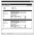
図13は本発明の第2の実施の形態に係るクライアント装置1301の表示部に表示されるメール通知設定画面の表示例を示す説明図である。本図では、デバイス装置1101に対して二つの異なる設定条件で電子メール通知設定が可能な例を示している。
【0111】
例えば、条件1では、デバイス装置1101でエラーが発生した場合のみ、Toアドレスで設定された通知先に対して電子メールが送信される。また、送信先を設定するToアドレスの入力部は、上記条件1のToアドレスに示すように、カンマ「,」で区切って複数のアドレスを設定することが可能である。図13において上記条件1で設定されたメールは、"prt-admin"@canon.co.jp"及び"Sys-admin@canon.co.jp"の二つの送信先に通知される。
【0112】
また、Reply-Toアドレス部で設定されたアドレス情報は、本電子メールの返信先アドレスとして、デバイス装置1101のネットワーク制御部1103に記憶され、本電子メール送信時に含まれる。
【0113】
図14は本発明の第2の実施の形態に係るデバイス装置1101のネットワーク制御部1103における、電子メール通知設定に係わるGUIデータをクライアント装置1301へ送信する際の処理を示すフローチャートである。尚、特に図示しないが、本処理を実行する制御プログラムは、ネットワーク制御部1103内の記憶媒体に格納されており、ネットワーク制御部1103により実行される。
【0114】
ネットワーク制御部1103は、クライアント装置1301からネットワーク1201を介してメール通知設定のGUIデータの送信要求が発生すると、ステップS1401で、メール通知設定情報記憶メモリ1107から、現在、デバイス装置1101に設定されているメール通知設定情報を読み出し、ステップS1402へ進む。
【0115】
ステップS1402では、ネットワーク制御部1103は、メール通知設定画面記憶メモリ1106に記憶されたメール通知設定表示画面データを読み出し、ステップS1403へ進む。
【0116】
ステップS1403で、ネットワーク制御部1103は、上記メール通知設定情報及び上記メール通知設定表示データに基づいて、上記図13で示すようなクライアント装置1301上で表示する際に参照されるGUIデータを生成し、ステップS1405へ進む。
【0117】
ステップS1405で、ネットワーク制御部1103は、上記生成されたGUIデータをネットワーク1201を介してクライアント装置1301へ送信し、本処理を終了する。
【0118】
図15は本発明の第2の実施の形態に係るデバイス装置1101のネットワーク制御部1103における、電子メール通知設定情報をデバイス装置1101に設定する際の処理を示すフローチャートである。尚、特に図示しないが、本処理を実行する制御プログラムは、ネットワーク制御部1103内の記憶媒体に格納されており、ネットワーク制御部1103により実行される。
【0119】
ステップS1501で、ネットワーク制御部1103は、クライアント装置1301からネットワーク1201を介してメール通知設定情報を受信すると、ステップS1502へ進む。
【0120】
ステップS1502で、ネットワーク制御部1103は、上記受信したメール通知設定情報と、ネットワーク制御部1103内のメール通知設定情報記憶メモリ1107に記憶されたメール通知設定情報との内容を比較する。メール通知設定情報に変更が有ると判定した場合には、ステップS1503へ進み、メール通知設定情報に変更無しと判定した場合には、本処理を終了する。
【0121】
ステップS1503で、ネットワーク制御部1103は、上記受信したメール通知設定情報に応じて、メール通知設定情報記憶メモリ1107に記憶されたメール通知設定情報を更新し、ステップS1504へ進む。
【0122】
ステップS1504で、ネットワーク制御部1103は、上記受信したメール通知設定情報に応じて、デバイス装置1101の状態変化の通知条件を変更する必要があるか否かを判定する。デバイス装置1101の状態変化の通知条件を変更する必要がある場合には、ステップS1505へ進み、デバイス装置1101の状態変化の通知条件を変更する必要がない場合には、本処理を終了する。
【0123】
以上説明したように、本発明の第2の実施の形態に係るネットワークシステムによれば、デバイス装置1101は、デバイス装置の状態に関する状態情報に応じた自然言語に基づくメッセージを含む電子メールをクライアント装置1301に送信するための送信設定情報を記憶するメール通知設定情報記憶メモリ1107、クライアント装置1301上で表示される送信設定情報のGUIデータの生成に必要な画面情報を記憶するメール通知設定画面記憶メモリ1106、送信設定情報及び画面情報に基づきGUIデータを生成するメール通知設定画面生成部1105、生成したGUIデータをクライアント装置1301に送信するネットワークI/F1114を備えているため、下記のような作用及び効果を奏する。
【0124】
上記構成において、デバイス装置1101の状態情報を電子メールで通知する際に必要な設定処理を、クライアント装置1301上でデバイス装置1101の現在の設定情報を確認しながら変更することが可能となる。
【0125】
即ち、任意のクライアント装置1301からデバイス装置1101に対し、専用のアプリケーションを用いることなく、デバイス装置1101を管理するための情報を取得し転送するように指示することが可能となる。
【0126】
また、デバイス装置1101から送信する電子メールに、該電子メールに対する返信先アドレスとして、例えばデバイス装置の管理者や保守担当者等のメールアドレスを予め設定しておくことで、電子メールを受信したユーザが管理者や保守担当者等のメールアドレスを意識することなく、適切な連絡先へデバイス装置1101に関する問い合わせをすることが可能となる。
【0127】
また、デバイス装置1101の状態種別に応じて、例えばデバイスエラーであれば保守担当者のメールアドレス、消耗品交換要求であれば備品管理者のメールアドレスを、返信先アドレスとして設定することで、デバイス装置1101の状態に応じたより適切な連絡先への迅速な問い合わせが可能となる。
【0128】
従って、デバイス装置の維持管理に係るユーザ負担をより一層軽減することが可能なシステムを提供することが可能となる効果を奏する。
【0129】
[他の実施の形態]
(1)本発明の上記第1の実施の形態において、電子メールで通知するデバイス装置の状態変化として、上記エラー及び消耗部品交換要求に加え、例えば用紙が少ない等のワーニングや印刷処理の終了等の状態変化に応じて、電子メールを送信してもよい。また、デバイス装置の状態を通知する電子メールに付加する情報として、デバイス装置のIPアドレスやFAX番号等のアドレス情報を付加してもよい。
【0130】
(2)本発明の上記第2の実施の形態において、デバイス装置に対して設定する電子メールの通知タイミングとして、例えば紙詰まりのエラーのみを通知する等、デバイス装置の特定の状態に限定して設定するようにしてもよく、また、その際の設定方法として、直接ステータスコードを入力するようにしてもよい。
【0131】
(3)本発明の上記第2の実施の形態において、設定可能な電子メールの通知設定条件の数は二つに限定されるものではなく、複数の通知設定条件を設定することも可能であることは言うまでもない。
【0132】
(4)本発明の上記第1及び第2の実施の形態において、ネットワーク上に接続するデバイス装置として画像形成機能を有するプリンタの場合を例に挙げたが、プリンタの他に例えば画像形成機能及び画像読取機能を有する複写機や複合機(MFP)を接続してもよい。
【0133】
(5)本発明の上記第1及び第2の実施の形態において、ネットワーク上にクライアント装置及びデバイス装置を1台ずつ接続した場合を例に挙げたが、クライアント装置及びデバイス装置の接続台数は任意台数とすることができる。
【0134】
(6)本発明の上記第1及び第2の実施の形態において、電子メールに対する返信先アドレスとして、デバイス装置の管理者のメールアドレス、デバイス装置の保守担当者のメールアドレス、デバイス装置の備品管理者のメールアドレスを例に挙げたが、ユーザから適切な連絡先へ迅速な問い合わせが可能なメールアドレスであればよい。
【0135】
尚、本発明は、複数の機器から構成されるシステムに適用しても、1つの機器からなる装置に適用してもよい。上述した実施形態の機能を実現するソフトウエアのプログラムコードを記憶した記憶媒体等の媒体をシステム或いは装置に供給し、そのシステム或いは装置のコンピュータ(またはCPUやMPU)が記憶媒体等の媒体に格納されたプログラムコードを読み出し実行することによっても、達成されることは言うまでもない。
【0136】
この場合、記憶媒体等の媒体から読み出されたプログラムコード自体が上述した実施形態の機能を実現することになり、そのプログラムコードを記憶した記憶媒体等の媒体は本発明を構成することになる。プログラムコードを供給するための記憶媒体等の媒体としては、例えば、フロッピーディスク、ハードディスク、光ディスク、光磁気ディスク、CD−ROM、CD−R、磁気テープ、不揮発性のメモリカード、ROM、或いはネットワークを介したダウンロードなどを用いることができる。
【0137】
また、コンピュータが読み出したプログラムコードを実行することにより、上述した実施形態の機能が実現されるだけでなく、そのプログラムコードの指示に基づき、コンピュータ上で稼動しているOSなどが実際の処理の一部または全部を行い、その処理によって上述した実施形態の機能が実現される場合も含まれることは言うまでもない。
【0138】
更に、記憶媒体等の媒体から読み出されたプログラムコードが、コンピュータに挿入された機能拡張ボードやコンピュータに接続された機能拡張ユニットに備わるメモリに書き込まれた後、そのプログラムコードの指示に基づき、その機能拡張ボードや機能拡張ユニットに備わるCPUなどが実際の処理の一部または全部を行い、その処理によって上述した実施形態の機能が実現される場合も含まれることは言うまでもない。
【0139】
図17は本発明のデータ転送方法を実行するプログラム及び関連データが記憶媒体からコンピュータ等の装置に供給される概念例を示す説明図である。本発明のデータ転送方法を実行するプログラム及び関連データは、フロッピーディスクやCD−ROM等の記憶媒体1701をコンピュータ等の装置1702に装備された記憶媒体ドライブの挿入口1703に挿入することで供給される。その後、本発明のデータ転送方法を実行するプログラム及び関連データを、記憶媒体1701から一旦ハードディスクにインストールしハードディスクからRAMにロードするか、或いはハードディスクにインストールせずに直接RAMにロードすることで、当該プログラム及び関連データを実行することが可能となる。
【0140】
この場合、本発明の第1〜第2の実施の形態に係るネットワークシステムにおいて、本発明のデータ転送方法を実行するプログラムを実行させる場合は、例えば上記図17を参照して説明したようなコンピュータ等の装置を介してネットワークシステムを構成する各装置に当該プログラム及び関連データを供給するか、或いはネットワークシステムを構成する各装置に予め当該プログラム及び関連データを格納しておくことで、プログラム実行が可能となる。
【0141】
図16は本発明のデータ転送方法を実行するプログラム及び関連データを記憶した記憶媒体の記憶内容の構成例を示す説明図である。記憶媒体は、例えばボリューム情報1601、ディレクトリ情報1602、プログラム実行ファイル1603、プログラム関連データファイル1604等の記憶内容で構成される。本発明のデータ転送方法を実行するプログラムは、上記各フローチャートに基づきプログラムコード化されたものである。
【0142】
【発明の効果】
以上説明したように、本発明によれば、デバイス装置で発生し得る複数の状態のそれぞれに対応付けられたメッセージであって、ユーザから入力されることなく前もって保持されているメッセージのうち、デバイス装置で発生した状態に対応する第1のメッセージ、設定画面を介してユーザから入力され、デバイス装置で発生し得る複数の状態のそれぞれに対応付けて保持されているメッセージのうち、デバイス装置で発生した状態に対応する第2のメッセージ、送信先情報、及び返信先情報に基づき作成した電子メールデータをクライアント装置へ送信するので、デバイス装置を管理するユーザに対し、デバイス装置の状態を適切に通知することが可能となる。
【0143】
また、任意のクライアント装置からデバイス装置に対し、専用のアプリケーションを用いることなく、デバイス装置を管理するための情報を取得し転送するように指示することが可能となる。
【0144】
また、デバイス装置の各状態を示すメッセージをデバイス装置のデバイス制御部に保持することで、クライアント装置及びデバイス装置間のデータ転送処理を担うデータ転送処理装置(ネットワーク制御部)が、デバイス装置に依存する情報を保持する必要がなくなるため、同じシステム構成からなり異なるデバイス制御部を備えたデバイス装置に対し、上記データ転送処理装置(ネットワーク制御部)をそのまま適用することが可能となる。
【0145】
また、デバイス装置から送信する電子メールに、該電子メールに対する返信先アドレスとして、例えばデバイス装置の管理者や保守担当者等のメールアドレスを予め設定しておくことで、電子メールを受信したユーザが管理者や保守担当者等のメールアドレスを意識することなく、適切な連絡先へデバイス装置に関する問い合わせをすることが可能となる。
【0146】
また、デバイス装置の状態種別に応じて、例えばデバイスエラーであれば保守担当者のメールアドレス、消耗品交換要求であれば備品管理者のメールアドレスを、返信先アドレスとして設定することで、デバイス装置の状態に応じたより適切な連絡先への迅速な問い合わせが可能となる。
【0147】
従って、デバイス装置の維持管理に係るユーザ負担をより一層軽減することが可能なシステムを提供することが可能となる効果を奏する。
【0148】
また、本発明のデバイス装置、本発明のネットワークシステム、本発明のデータ転送方法、本発明の記憶媒体においても、上記と同様に、デバイス装置の維持管理に係るユーザ負担をより一層軽減することが可能なシステムを提供することが可能となる効果を奏する。
【図面の簡単な説明】
【図1】本発明の第1の実施の形態に係るデバイス装置とクライアント装置とメールサーバ装置を備えたネットワークシステムの構成例を示すブロック図である。
【図2】図1に示したデバイス装置のデバイス制御部における第一のデータ転送処理の一例を示すフローチャートである。
【図3】図1に示したデバイス装置のデバイス制御部から送信されるデバイス装置の状態に関する送信データの書式例を示す説明図である。
【図4】図3に示した書式例に従ったデバイス装置のデバイスデバイス制御部からの送信データの一例を示す説明図である。
【図5】図1に示したデバイス装置のデバイス制御部における第二のデータ転送処理の一例を示すフローチャートである。
【図6】図1に示したデバイス装置のデバイス制御部に記憶されるデバイス装置の各状態を表すステータスメッセージデータの一例を示す説明図である。
【図7】図1に示したデバイス装置のネットワーク制御部におけるデータ転送処理の一例を示すフローチャートである。
【図8】図1に示したデバイス装置のネットワーク制御部に記憶されるデバイス装置の各エラー状態に対応するステータスコードの一例を示す説明図である。
【図9】図1に示したデバイス装置のネットワーク制御部に記憶されるデバイス装置の各消耗品交換要求状態に対応するステータスコードの一例を示す説明図である。
【図10】図7に示したデバイス装置のネットワーク制御部が生成したデバイス装置でエラーが発生した際の電子メールの送信例を示す説明図である。
【図11】図7に示したデバイス装置のネットワーク制御部が生成したデバイス装置で消耗品交換要求が発生した際の電子メールの送信例を示す説明図である。
【図12】本発明の第2の実施の形態に係るデバイス装置とクライアント装置を備えたネットワークシステムの構成例を示したブロック図である。
【図13】図12に示したクライアント装置で表示されるメール通知設定画面の表示例を示す説明図である。
【図14】図12に示したデバイス装置のネットワーク制御部における第一のデータ転送処理の一例を示すフローチャートである。
【図15】図12に示したデバイス装置のネットワーク制御部における第一のデータ転送処理の一例を示すフローチャートである。
【図16】本発明のデータ転送方法を実行するプログラム及び関連データを記憶した記憶媒体の記憶内容の構成例を示す説明図である。
【図17】本発明のデータ転送方法を実行するプログラム及び関連データが記憶媒体からコンピュータ等の装置に供給される概念例を示す説明図である。
【符号の説明】
101、1101 デバイス装置
102、1102 デバイス制御部
103、1103 ネットワーク制御部(データ転送処理装置)
107 デバイス状態変化検知部
108 メールメッセージ生成部(作成手段)
109 ステータスメッセージ取得部
110 ステータスメッセージ送信部
111 ステータスメッセージデータ部
112 メールヘッダ・フッダデータ部(送信先情報記憶手段)
113 メール送信部(電子メールデータ送信手段)
201、1201 ネットワーク(通信媒体)
301、1301 クライアント装置
302 メールサーバ装置
1105 メール通知設定画面生成部(生成手段)
1106 メール通知設定画面記憶メモリ
1107 メール通知設定情報記憶メモリ
1108 メール通知設定情報取得部
1110 デバイス状態通知条件設定部
1114 ネットワークI/F(画面データ送信手段)[0001]
BACKGROUND OF THE INVENTION
The present invention relates to a data transfer processing device, a device device,Data transfer processing device control method, device device control method,as well asprogramIn particular, data transfer processing between a server device, a client device, a network control unit that performs an interface to the network, and a device device that includes a device control unit that controls the device itself, connected to the network. , Data transfer processing device suitable for setting of processing performed in data transfer, control in device device, device device,Data transfer processing device control method, device device control method,as well asprogramAbout.
[0002]
[Prior art]
2. Description of the Related Art Conventionally, there is known a network system configured to connect a client device and various device devices on a network, and acquire and monitor device device information by the client device. In this type of network system, a dedicated application for acquiring device device information is incorporated in the client device in advance, and the device device information is acquired if the application is not operating on the client device. I couldn't.
[0003]
In order to solve the above problem, for example, as described in Japanese Patent Application Laid-Open No. 10-149302, it is configured to transfer information on the state change of the device device to the client device via the server device as an electronic mail. A network system has been proposed. In addition, there is a network system that notifies the state of the device device notified by electronic mail only to a state specified in advance.
[0004]
[Problems to be solved by the invention]
However, in the above-described conventional example, the information on the device notified by e-mail is a text created in a human-readable natural language based on information acquired from the device by a data transfer processing device connected to the device. It is converted into a message and sent. Therefore, the data transfer processing device connected to the device device needs to hold a text message corresponding to each status information of the device device connected in advance.
[0005]
In the above conventional example, when the data transfer processing device is connected to a different type of device device, it is necessary to hold the status information acquired from the device device as a text message according to the type of each device device. Therefore, there is a problem that the storage capacity of the storage device of the data transfer processing device increases every time the type of the corresponding device device increases.
[0006]
In the above conventional example, since the data transfer processing device holds the text message corresponding to each status information of each device device, the data transfer processing device is highly dependent on the model of the device device and lacks versatility. There was also a problem.
[0007]
Furthermore, in the above-described conventional example, when the state of the device device notified by e-mail is limited to the state specified in advance, it is necessary to set a notification condition for each state of the device device. There is a problem that the setting burden on the user increases as the number increases.
[0008]
The present invention has been made in view of the above points., DeThe device device status to the user who manages the deviceProperly notifyMade it possibleData transfer processing device control method, device device control method,as well asprogramTo provideEyesTarget.
[0013]
[Means for Solving the Problems]
In order to achieve the above object, a data transfer processing device of the present invention is a data transfer processing device for controlling data transfer between a client device and a device device connected via a communication medium, the device deviceCan occur in multipleStatusAssociated with each ofA message that is held in advance without input from the userCorresponds to the state of the device that occurred in the deviceA first acquisition means for acquiring a first message and a user input via a setting screen;Corresponding to each of a plurality of states that can occur in the device deviceRetainedCorresponds to the state of the device that occurred in the deviceSecond acquisition means for acquiring a second message, first message acquired by the first acquisition means, second message acquired by the second acquisition means, transmission destination information, and reply destination information And creating means for creating e-mail data, and e-mail data transmitting means for sending the e-mail data created by the creating means to the client device, wherein the creating means creates the e-mail data When the device apparatusOccurred inA different address is set as e-mail data reply destination information according to the state, and the first message and the second message are set as body information of the e-mail data.
[0020]
To achieve the above object, a device apparatus of the present invention is a device apparatus capable of communicating with a client apparatus via a communication medium, and the device apparatusCan occur in multipleStatusAssociated with each ofA message that is held in advance without input from the userCorresponds to the state of the device that occurred in the deviceA first acquisition means for acquiring a first message and a user input via a setting screen;Corresponding to each of a plurality of states that can occur in the device deviceRetainedCorresponds to the state of the device that occurred in the deviceSecond acquisition means for acquiring a second message, first message acquired by the first acquisition means, second message acquired by the second acquisition means, transmission destination information, and reply destination information And creating means for creating e-mail data, and e-mail data transmitting means for sending the e-mail data created by the creating means to the client device, wherein the creating means creates the e-mail data When the device apparatusOccurred inA different address is set as e-mail data reply destination information according to the state, and the first message and the second message are set as body information of the e-mail data.
[0029]
To achieve the above object, a device apparatus of the present invention is a device apparatus capable of communicating with a client apparatus via a communication medium, and the device apparatusCan occur in multipleStatusAssociated with each ofA message that is held in advance without input from the userCorresponds to the state of the device that occurred in the deviceA first acquisition means for acquiring a first message and a user input via a setting screen;Corresponding to each of a plurality of states that can occur in the device deviceRetainedCorresponds to the state of the device that occurred in the deviceSecond acquisition means for acquiring a second message, first message acquired by the first acquisition means, second message acquired by the second acquisition means, transmission destination information, and reply destination information And creating means for creating e-mail data, and e-mail data transmitting means for sending the e-mail data created by the creating means to the client device, wherein the creating means creates the e-mail data In this case, the first message and the second message are set as body information of electronic mail data.
[0038]
In order to achieve the above object, a control method for a data transfer processing device of the present invention is a control method for a data transfer processing device that controls data transfer between a client device and a device device connected via a communication medium, Device deviceCan occur in multipleStatusAssociated with each ofA message that is held in advance without input from the userCorresponds to the state of the device that occurred in the deviceThe first acquisition step of acquiring the first message, and input from the user via the setting screen,Corresponding to each of a plurality of states that can occur in the device deviceRetainedCorresponds to the state of the device that occurred in the deviceA second acquisition step of acquiring a second message; a first message acquired in the first acquisition step; a second message acquired in the second acquisition step; destination information; and reply destination information A creation step for creating email data based on the email data, and an email data transmission step for sending the email data created in the creation step to the client device. In the creation step, the email data is created. When the device apparatusOccurred inA different address is set as e-mail data reply destination information according to the state, and the first message and the second message are set as body information of the e-mail data.
[0047]
To achieve the above object, a device apparatus control method according to the present invention is a device apparatus control method capable of communicating with a client apparatus via a communication medium, the device apparatus comprising:Can occur in multipleStatusAssociated with each ofA message that is held in advance without input from the userCorresponds to the state of the device that occurred in the deviceThe first acquisition step of acquiring the first message, and input from the user via the setting screen,Corresponding to each of a plurality of states that can occur in the device deviceRetainedCorresponds to the state of the device that occurred in the deviceA second acquisition step of acquiring a second message; a first message acquired in the first acquisition step; a second message acquired in the second acquisition step; destination information; and reply destination information A creation step for creating email data based on the email data, and an email data transmission step for sending the email data created in the creation step to the client device. In the creation step, the email data is created. When the device apparatusOccurred inA different address is set as e-mail data reply destination information according to the state, and the first message and the second message are set as body information of the e-mail data.
In order to achieve the above object, a device apparatus control method of the present invention is a device apparatus control method capable of communicating with a client apparatus via a communication medium, the device apparatus comprising:Can occur in multipleStatusAssociated with each ofA message that is held in advance without input from the userCorresponds to the state of the device that occurred in the deviceThe first acquisition step of acquiring the first message, and input from the user via the setting screen,Corresponding to each of a plurality of states that can occur in the device deviceRetainedCorresponds to the state of the device that occurred in the deviceA second acquisition step of acquiring a second message; a first message acquired in the first acquisition step; a second message acquired in the second acquisition step; destination information; and reply destination information A creation step for creating email data based on the email data, and an email data transmission step for sending the email data created in the creation step to the client device. In the creation step, the email data is created. In this case, the first message and the second message are set as body information of electronic mail data.
[0056]
DETAILED DESCRIPTION OF THE INVENTION
First, before describing embodiments of the present invention, an outline of the present invention will be described.
[0057]
According to the present invention, in response to a change in the state of the device apparatus, the state information of the device apparatus is acquired as a text message created in a human-readable natural language, and the state information of the device apparatus is notified to the client apparatus by e-mail. Is. Further, the error level of each state of the device apparatus is defined, and the state of the device apparatus is notified by e-mail to the notification destination set for each error level.
[0058]
Also, notification information set according to the error level of the state generated in the device apparatus is added, and the state of the device apparatus is notified by electronic mail. Hereinafter, embodiments of the present invention will be described in detail with reference to the drawings.
[0059]
[First Embodiment]
FIG. 1 is a block diagram showing a configuration of a network system including a device apparatus, a client apparatus, and a mail server apparatus according to the first embodiment of the present invention.
[0060]
The first embodiment of the present invention corresponds to claim 1. The network system according to the first embodiment of the present invention includes a
[0061]
In detail, the
[0062]
The
[0063]
The
[0064]
In the
[0065]
In addition, the mail
[0066]
In this case, in the first embodiment of the present invention, the reply address for the above e-mail is, for example, the e-mail address of the administrator of the device apparatus, the e-mail address of the person in charge of maintenance of the device apparatus, and the equipment management of the device apparatus An e-mail address such as a person's e-mail address is set so that the user can promptly contact the appropriate contact.
[0067]
In the
[0068]
The mail header /
[0069]
Next, the data transfer processing procedure in the
[0070]
FIG. 2 is a flowchart showing processing when the
[0071]
In step S <b> 201, the
[0072]
In step S <b> 202, the
[0073]
In step S203, the
[0074]
In step S <b> 204, the
[0075]
FIG. 4 is an explanatory diagram showing an example of transmission data according to the first embodiment of the present invention. In the transmission data example of FIG. 4, the state change notification type “0x02” indicates a state change accompanying an error, and the status code “40309” indicates an abnormal state of the oil pump of the
[0076]
FIG. 5 shows a case where the state information of the
[0077]
In step S <b> 501, the
[0078]
In step S502, the
[0079]
In step S503, the
[0080]
Thereby, for example, when a message acquisition request corresponding to the status code “40300” is received from the
[0081]
FIG. 7 shows the status information of the
[0082]
In step S701, the
[0083]
In step S702, the
[0084]
In step S703, the
[0085]
In step S704, the
[0086]
In step S705, the
[0087]
In step S706, the
[0088]
FIG. 8 is an explanatory diagram showing status codes corresponding to each error state in the
[0089]
FIG. 9 is an explanatory diagram showing status codes corresponding to replacement requests for various consumable parts used in the
[0090]
FIG. 10 illustrates an example of sending an e-mail when an error occurs in the
[0091]
[0092]
[0093]
FIG. 11 shows when a change in the status of a replacement request for a consumable part of the
[0094]
As described above, according to the network system according to the first embodiment of the present invention, the
[0095]
In the above configuration, when a state change such as an error occurs in the
[0096]
That is, since the transmission data created based on the message according to the state information of the
[0097]
In addition, by holding messages indicating the states of the
[0098]
In addition, the e-mail received from the e-mail transmitted from the
[0099]
Further, according to the status type of the
[0100]
Therefore, there is an effect that it is possible to provide a system capable of further reducing the user burden related to the maintenance management of the device apparatus.
[0101]
[Second Embodiment]
FIG. 12 is a block diagram showing a configuration of a network system including a device apparatus and a client apparatus according to the second embodiment of the present invention.. BookThe network system according to the second embodiment of the present invention includes a
[0102]
Specifically, the
[0103]
In the
[0104]
The mail notification setting
[0105]
In this case, in the second embodiment of the present invention, as the reply address for the above-mentioned e-mail, for example, the e-mail address of the administrator of the device apparatus, the e-mail address of the person in charge of maintenance of the device apparatus, the equipment management of the device apparatus An e-mail address such as a person's e-mail address is set so that the user can promptly contact the appropriate contact.
[0106]
The mail notification setting
[0107]
In the device control unit 1102, the device state notification condition setting
[0108]
Further, the device control unit 1102 is a state detection unit (not shown) for detecting a state generated in the
[0109]
Next, operations in the network system according to the second embodiment of the present invention configured as described above will be described in detail with reference to FIGS. 12, 13, 14, and 15. FIG.
[0110]
FIG. 13 is an explanatory diagram showing a display example of a mail notification setting screen displayed on the display unit of the
[0111]
For example, under
[0112]
Further, the address information set in the Reply-To address part is stored in the
[0113]
FIG. 14 is a flowchart showing a process when the
[0114]
When a transmission request for mail notification setting GUI data is generated from the
[0115]
In step S1402, the
[0116]
In step S1403, the
[0117]
In step S1405, the
[0118]
FIG. 15 is a flowchart showing processing when setting e-mail notification setting information in the
[0119]
In step S1501, when the
[0120]
In step S1502, the
[0121]
In step S1503, the
[0122]
In step S1504, the
[0123]
As described above, according to the network system according to the second embodiment of the present invention, the
[0124]
In the above configuration, the setting process required when notifying the status information of the
[0125]
That is, an
[0126]
In addition, a user who receives an e-mail by setting in advance an e-mail address of, for example, a device apparatus administrator or a maintenance person in the e-mail transmitted from the
[0127]
Further, depending on the status type of the
[0128]
Therefore, there is an effect that it is possible to provide a system capable of further reducing the user burden related to the maintenance management of the device apparatus.
[0129]
[Other embodiments]
(1) In the first embodiment of the present invention, as a status change of the device device notified by e-mail, in addition to the error and the consumable part replacement request, for example, a warning such as a shortage of sheets, the end of the printing process, etc. An e-mail may be sent according to the state change. Further, address information such as the IP address or FAX number of the device apparatus may be added as information to be added to the e-mail notifying the state of the device apparatus.
[0130]
(2) In the second embodiment of the present invention, the e-mail notification timing set for the device apparatus is limited to a specific state of the device apparatus, such as notifying only a paper jam error. You may make it set, and you may make it input a status code directly as the setting method in that case.
[0131]
(3) In the second embodiment of the present invention, the number of e-mail notification setting conditions that can be set is not limited to two, and a plurality of notification setting conditions can also be set. Needless to say.
[0132]
(4) In the first and second embodiments of the present invention, the case of a printer having an image forming function as an example of a device device connected to a network has been described as an example. A copier or multifunction peripheral (MFP) having an image reading function may be connected.
[0133]
(5) In the first and second embodiments of the present invention, the case where one client device and one device device are connected on the network is taken as an example, but the number of client devices and device devices connected is arbitrary. It can be the number.
[0134]
(6) In the first and second embodiments of the present invention, as a reply-to address for an e-mail, an e-mail address of a device apparatus administrator, an e-mail address of a device apparatus maintenance person, and device apparatus equipment management The mail address of the person is taken as an example, but any mail address that can promptly contact the appropriate contact from the user may be used.
[0135]
The present invention may be applied to a system composed of a plurality of devices or an apparatus composed of a single device. A medium such as a storage medium storing software program codes for realizing the functions of the above-described embodiments is supplied to the system or apparatus, and the computer (or CPU or MPU) of the system or apparatus stores the medium in the storage medium or the like. Needless to say, this can also be achieved by reading and executing the program code.
[0136]
In this case, the program code itself read from the medium such as a storage medium realizes the functions of the above-described embodiments, and the medium such as the storage medium storing the program code constitutes the present invention. . Examples of the medium such as a storage medium for supplying the program code include a floppy disk, a hard disk, an optical disk, a magneto-optical disk, a CD-ROM, a CD-R, a magnetic tape, a nonvolatile memory card, a ROM, and a network. Downloads can be used.
[0137]
Further, by executing the program code read out by the computer, not only the functions of the above-described embodiments are realized, but also the OS running on the computer based on the instruction of the program code performs the actual processing. Needless to say, a case where the function of the above-described embodiment is realized by performing part or all of the processing is included.
[0138]
Furthermore, after the program code read from a medium such as a storage medium is written in a memory provided in a function expansion board inserted in the computer or a function expansion unit connected to the computer, based on the instruction of the program code, It goes without saying that the CPU of the function expansion board or function expansion unit performs part or all of the actual processing and the functions of the above-described embodiments are realized by the processing.
[0139]
FIG. 17 is an explanatory diagram showing a conceptual example in which a program for executing the data transfer method of the present invention and related data are supplied from a storage medium to an apparatus such as a computer. A program for executing the data transfer method of the present invention and related data are supplied by inserting a
[0140]
In this case, in the network system according to the first to second embodiments of the present invention, when the program for executing the data transfer method of the present invention is executed, for example, a computer as described with reference to FIG. The program and the related data are supplied to each device constituting the network system via the device or the like, or the program and the related data are stored in advance in each device constituting the network system. It becomes possible.
[0141]
FIG. 16 is an explanatory diagram showing a configuration example of storage contents of a storage medium storing a program for executing the data transfer method of the present invention and related data. The storage medium includes storage contents such as
[0142]
【The invention's effect】
As described above, according to the present invention, the device apparatusCan occur in multipleStatusAssociated with each ofA message that is held in advance without input from the userCorresponds to the state of the device that occurred in the deviceFirst message, input from the user via the setting screen,Corresponding to each of multiple states that can occur in the deviceRetainedCorresponds to the state of the device that occurred in the deviceSince the e-mail data created based on the second message, the transmission destination information, and the reply destination information is transmitted to the client apparatus, it is possible to appropriately notify the user who manages the device apparatus of the state of the device apparatus. Become.
[0143]
Further, it is possible to instruct the client device to acquire and transfer information for managing the device device without using a dedicated application from any client device.
[0144]
In addition, a message indicating each state of the device device is held in the device control unit of the device device, so that the data transfer processing device (network control unit) responsible for data transfer processing between the client device and the device device depends on the device device. Therefore, it is possible to directly apply the data transfer processing device (network control unit) to device devices having the same system configuration and different device control units.
[0145]
In addition, as a reply-to address for the e-mail, for example, an e-mail address of a device apparatus administrator or maintenance person is set in advance in the e-mail transmitted from the device apparatus. It is possible to make an inquiry about the device device to an appropriate contact without being aware of the e-mail address of an administrator or maintenance staff.
[0146]
Also, according to the status type of the device device, for example, if a device error occurs, the email address of the person in charge of maintenance is set as the reply address, and the email address of the equipment manager is set as the reply destination address if a consumable replacement request is made. It is possible to promptly contact a more appropriate contact according to the status of the user.
[0147]
Therefore, there is an effect that it is possible to provide a system capable of further reducing the user burden related to the maintenance management of the device apparatus.
[0148]
Further, in the device apparatus of the present invention, the network system of the present invention, the data transfer method of the present invention, and the storage medium of the present invention, the user burden related to the maintenance management of the device apparatus can be further reduced as described above. There is an effect that a possible system can be provided.
[Brief description of the drawings]
FIG. 1 is a block diagram illustrating a configuration example of a network system including a device device, a client device, and a mail server device according to a first embodiment of the present invention.
FIG. 2 is a flowchart illustrating an example of first data transfer processing in a device control unit of the device apparatus illustrated in FIG. 1;
3 is an explanatory diagram illustrating a format example of transmission data regarding the state of a device apparatus transmitted from a device control unit of the device apparatus illustrated in FIG. 1; FIG.
4 is an explanatory diagram illustrating an example of transmission data from a device device control unit of the device device according to the format example illustrated in FIG. 3;
FIG. 5 is a flowchart illustrating an example of second data transfer processing in the device control unit of the device apparatus illustrated in FIG. 1;
6 is an explanatory diagram showing an example of status message data representing each state of the device device stored in the device control unit of the device device shown in FIG. 1; FIG.
7 is a flowchart illustrating an example of a data transfer process in a network control unit of the device apparatus illustrated in FIG. 1;
FIG. 8 is an explanatory diagram illustrating an example of a status code corresponding to each error state of the device device stored in the network control unit of the device device illustrated in FIG. 1;
FIG. 9 is an explanatory diagram illustrating an example of a status code corresponding to each consumable replacement request state of the device device stored in the network control unit of the device device illustrated in FIG. 1;
10 is an explanatory diagram showing an example of sending an e-mail when an error occurs in the device device generated by the network control unit of the device device shown in FIG. 7;
11 is an explanatory diagram showing an example of sending an e-mail when a consumable replacement request is generated in the device device generated by the network control unit of the device device shown in FIG. 7;
FIG. 12 is a block diagram illustrating a configuration example of a network system including a device device and a client device according to a second embodiment of the present invention.
13 is an explanatory diagram showing a display example of a mail notification setting screen displayed on the client device shown in FIG. 12. FIG.
14 is a flowchart illustrating an example of a first data transfer process in a network control unit of the device apparatus illustrated in FIG. 12;
15 is a flowchart illustrating an example of a first data transfer process in a network control unit of the device apparatus illustrated in FIG. 12;
FIG. 16 is an explanatory diagram showing a configuration example of storage contents of a storage medium storing a program for executing a data transfer method of the present invention and related data;
FIG. 17 is an explanatory diagram showing a conceptual example in which a program for executing a data transfer method of the present invention and related data are supplied from a storage medium to an apparatus such as a computer.
[Explanation of symbols]
101, 1101 device apparatus
102, 1102 Device control unit
103, 1103 Network control unit (data transfer processing device)
107 Device state change detectionPart
108 Mail message generator(WorkFormation means)
109 Status message acquisition unit
110 Status message transmitter
111 Status message data section
112 Mail header / footer data part (destination information storage means)
113 Mail sending part (e-maildataTransmission means)
201, 1201 Network (communication medium)
301, 1301 Client device
302 mail server device
1105 Mail notification setting screen generator(LivingFormation means)
1106 Mail notification setting screen storage memory
1107 Mail notification setting information storage memoRe
1108 Mail notification setting information acquisitionPart
1110 Device status notification condition settingPart
1114 Network I / F (screenData transmission means)
Claims (13)
前記デバイス装置で発生し得る複数の状態のそれぞれに対応付けられたメッセージであって、ユーザから入力されることなく前もって保持されているメッセージのうち、前記デバイス装置で発生した状態に対応する第1のメッセージを取得する第1の取得手段と、
設定画面を介してユーザから入力され、前記デバイス装置で発生し得る複数の状態のそれぞれに対応付けて保持されているメッセージのうち、前記デバイス装置で発生した状態に対応する第2のメッセージを取得する第2の取得手段と、
前記第1の取得手段が取得した第1のメッセージ、前記第2の取得手段が取得した第2のメッセージ、送信先情報、及び返信先情報に基づき電子メールデータを作成する作成手段と、
前記作成手段が作成した電子メールデータを前記クライアント装置に送信する電子メールデータ送信手段とを有し、
前記作成手段は、前記電子メールデータを作成する際に、前記デバイス装置で発生した状態に応じて異なるアドレスを電子メールデータの返信先情報として設定し、前記第1のメッセージ及び前記第2のメッセージを電子メールデータの本文情報として設定することを特徴とするデータ転送処理装置。A data transfer processing device for controlling data transfer between a client device and a device device connected via a communication medium,
A message that is associated with each of a plurality of states that can occur in the device device , and is a first message that corresponds to a state that occurs in the device device among messages that are held in advance without being input by the user. First acquisition means for acquiring the message of
A second message corresponding to a state generated in the device apparatus is acquired from among messages stored in association with each of a plurality of states that can be generated in the device apparatus through a setting screen. A second acquisition means for:
Creating means for creating e-mail data based on the first message obtained by the first obtaining means, the second message obtained by the second obtaining means, transmission destination information, and reply destination information;
E-mail data sending means for sending the e-mail data created by the creating means to the client device;
When creating the e-mail data, the creating means sets different addresses as return information of the e-mail data according to the state generated in the device device , and the first message and the second message Is set as the body information of the e-mail data.
前記作成手段は、前記送信先情報記憶手段に記憶された送信先情報を用いて前記電子メールデータを作成することを特徴とする請求項1又は2に記載のデータ転送処理装置。Further comprising a destination information storage means for storing the destination information;
The data transfer processing device according to claim 1, wherein the creating unit creates the e-mail data using the destination information stored in the destination information storage unit.
前記生成手段が生成した画面データを前記クライアント装置に送信する画面データ送信手段とを更に有することを特徴とする請求項1乃至4のいずれか1項に記載のデータ転送処理装置。Generating means for generating screen data representing the setting screen;
5. The data transfer processing device according to claim 1, further comprising a screen data transmission unit configured to transmit the screen data generated by the generation unit to the client device. 6.
前記作成手段は、前記電子メールデータに設定する送信先情報に対応付けて設定されている前記第2のメッセージを、当該電子メールデータの本文情報として設定することを特徴とする請求項1乃至6のいずれか1項に記載のデータ転送処理装置。In the setting screen, the second message can be set in association with each of a plurality of different pieces of destination information,
7. The creation unit sets the second message set in association with transmission destination information set in the electronic mail data as text information of the electronic mail data. The data transfer processing device according to any one of the above.
前記デバイス装置で発生し得る複数の状態のそれぞれに対応付けられたメッセージであって、ユーザから入力されることなく前もって保持されているメッセージのうち、前記デバイス装置で発生した状態に対応する第1のメッセージを取得する第1の取得手段と、
設定画面を介してユーザから入力され、前記デバイス装置で発生し得る複数の状態のそれぞれに対応付けて保持されているメッセージのうち、前記デバイス装置で発生した状態に対応する第2のメッセージを取得する第2の取得手段と、
前記第1の取得手段が取得した第1のメッセージ、前記第2の取得手段が取得した第2のメッセージ、送信先情報、及び返信先情報に基づき電子メールデータを作成する作成手段と、
前記作成手段が作成した電子メールデータを前記クライアント装置に送信する電子メールデータ送信手段とを有し、
前記作成手段は、前記電子メールデータを作成する際に、前記デバイス装置で発生した状態に応じて異なるアドレスを電子メールデータの返信先情報として設定し、前記第1のメッセージ及び前記第2のメッセージを電子メールデータの本文情報として設定することを特徴とするデバイス装置。A device device capable of communicating with a client device via a communication medium,
A message that is associated with each of a plurality of states that can occur in the device device , and is a first message that corresponds to a state that occurs in the device device among messages that are held in advance without being input by the user. First acquisition means for acquiring the message of
A second message corresponding to a state generated in the device apparatus is acquired from among messages stored in association with each of a plurality of states that can be generated in the device apparatus through a setting screen. A second acquisition means for:
Creating means for creating e-mail data based on the first message obtained by the first obtaining means, the second message obtained by the second obtaining means, transmission destination information, and reply destination information;
E-mail data sending means for sending the e-mail data created by the creating means to the client device;
When creating the e-mail data, the creating means sets different addresses as return information of the e-mail data according to the state generated in the device device , and the first message and the second message Is set as the body information of the e-mail data.
前記デバイス装置で発生し得る複数の状態のそれぞれに対応付けられたメッセージであって、ユーザから入力されることなく前もって保持されているメッセージのうち、前記デバイス装置で発生した状態に対応する第1のメッセージを取得する第1の取得手段と、
設定画面を介してユーザから入力され、前記デバイス装置で発生し得る複数の状態のそれぞれに対応付けて保持されているメッセージのうち、前記デバイス装置で発生した状態に対応する第2のメッセージを取得する第2の取得手段と、
前記第1の取得手段が取得した第1のメッセージ、前記第2の取得手段が取得した第2のメッセージ、送信先情報、及び返信先情報に基づき電子メールデータを作成する作成手段と、
前記作成手段が作成した電子メールデータを前記クライアント装置に送信する電子メールデータ送信手段とを有し、
前記作成手段は、前記電子メールデータを作成する際に、前記第1のメッセージ及び前記第2のメッセージを電子メールデータの本文情報として設定することを特徴とするデバイス装置。A device device capable of communicating with a client device via a communication medium,
A message that is associated with each of a plurality of states that can occur in the device device , and is a first message that corresponds to a state that occurs in the device device among messages that are held in advance without being input by the user. First acquisition means for acquiring the message of
A second message corresponding to a state generated in the device apparatus is acquired from among messages stored in association with each of a plurality of states that can be generated in the device apparatus through a setting screen. A second acquisition means for:
Creating means for creating e-mail data based on the first message obtained by the first obtaining means, the second message obtained by the second obtaining means, transmission destination information, and reply destination information;
E-mail data sending means for sending the e-mail data created by the creating means to the client device;
The creation device sets the first message and the second message as body information of email data when creating the email data.
前記デバイス装置で発生し得る複数の状態のそれぞれに対応付けられたメッセージであって、ユーザから入力されることなく前もって保持されているメッセージのうち、前記デバイス装置で発生した状態に対応する第1のメッセージを取得する第1の取得工程と、
設定画面を介してユーザから入力され、前記デバイス装置で発生し得る複数の状態のそれぞれに対応付けて保持されているメッセージのうち、前記デバイス装置で発生した状態に対応する第2のメッセージを取得する第2の取得工程と、
前記第1の取得工程で取得した第1のメッセージ、前記第2の取得工程で取得した第2のメッセージ、送信先情報、及び返信先情報に基づき電子メールデータを作成する作成工程と、
前記作成工程で作成した電子メールデータを前記クライアント装置に送信する電子メールデータ送信工程とを有し、
前記作成工程では、前記電子メールデータを作成する際に、前記デバイス装置で発生した状態に応じて異なるアドレスを電子メールデータの返信先情報として設定し、前記第1のメッセージ及び前記第2のメッセージを電子メールデータの本文情報として設定することを特徴とするデータ転送処理装置の制御方法。A data transfer processing device control method for controlling data transfer between a client device and a device device connected via a communication medium,
A message that is associated with each of a plurality of states that can occur in the device device , and is a first message that corresponds to a state that occurs in the device device among messages that are held in advance without being input by the user. A first acquisition step of acquiring the message of
A second message corresponding to a state generated in the device apparatus is acquired from among messages stored in association with each of a plurality of states that can be generated in the device apparatus through a setting screen. A second acquisition step,
A creation step for creating email data based on the first message acquired in the first acquisition step, the second message acquired in the second acquisition step, transmission destination information, and reply destination information;
An email data transmission step of transmitting the email data created in the creation step to the client device,
In the creating step, when creating the e-mail data, different addresses are set as e-mail data return destination information according to the state generated in the device device , and the first message and the second message are set. Is set as the body information of the e-mail data.
前記デバイス装置で発生し得る複数の状態のそれぞれに対応付けられたメッセージであって、ユーザから入力されることなく前もって保持されているメッセージのうち、前記デバイス装置で発生した状態に対応する第1のメッセージを取得する第1の取得工程と、
設定画面を介してユーザから入力され、前記デバイス装置で発生し得る複数の状態のそれぞれに対応付けて保持されているメッセージのうち、前記デバイス装置で発生した状態に対応する第2のメッセージを取得する第2の取得工程と、
前記第1の取得工程で取得した第1のメッセージ、前記第2の取得工程で取得した第2のメッセージ、送信先情報、及び返信先情報に基づき電子メールデータを作成する作成工程と、
前記作成工程で作成した電子メールデータを前記クライアント装置に送信する電子メールデータ送信工程とを有し、
前記作成工程では、前記電子メールデータを作成する際に、前記デバイス装置で発生した状態に応じて異なるアドレスを電子メールデータの返信先情報として設定し、前記第1のメッセージ及び前記第2のメッセージを電子メールデータの本文情報として設定することを特徴とするデバイス装置の制御方法。A device device control method capable of communicating with a client device via a communication medium,
A message that is associated with each of a plurality of states that can occur in the device device , and is a first message that corresponds to a state that occurs in the device device among messages that are held in advance without being input by the user. A first acquisition step of acquiring the message of
A second message corresponding to a state generated in the device apparatus is acquired from among messages stored in association with each of a plurality of states that can be generated in the device apparatus through a setting screen. A second acquisition step,
A creation step for creating email data based on the first message acquired in the first acquisition step, the second message acquired in the second acquisition step, transmission destination information, and reply destination information;
An email data transmission step of transmitting the email data created in the creation step to the client device,
In the creating step, when creating the e-mail data, different addresses are set as e-mail data return destination information according to the state generated in the device device , and the first message and the second message are set. Is set as the body information of the e-mail data.
前記デバイス装置で発生し得る複数の状態のそれぞれに対応付けられたメッセージであって、ユーザから入力されることなく前もって保持されているメッセージのうち、前記デバイス装置で発生した状態に対応する第1のメッセージを取得する第1の取得工程と、
設定画面を介してユーザから入力され、前記デバイス装置で発生し得る複数の状態のそれぞれに対応付けて保持されているメッセージのうち、前記デバイス装置で発生した状態に対応する第2のメッセージを取得する第2の取得工程と、
前記第1の取得工程で取得した第1のメッセージ、前記第2の取得工程で取得した第2のメッセージ、送信先情報、及び返信先情報に基づき電子メールデータを作成する作成工程と、
前記作成工程で作成した電子メールデータを前記クライアント装置に送信する電子メールデータ送信工程とを有し、
前記作成工程では、前記電子メールデータを作成する際に、前記第1のメッセージ及び前記第2のメッセージを電子メールデータの本文情報として設定することを特徴とするデバイス装置の制御方法。A device device control method capable of communicating with a client device via a communication medium,
A message that is associated with each of a plurality of states that can occur in the device device , and is a first message that corresponds to a state that occurs in the device device among messages that are held in advance without being input by the user. A first acquisition step of acquiring the message of
A second message corresponding to a state generated in the device apparatus is acquired from among messages stored in association with each of a plurality of states that can be generated in the device apparatus through a setting screen. A second acquisition step,
A creation step for creating email data based on the first message acquired in the first acquisition step, the second message acquired in the second acquisition step, transmission destination information, and reply destination information;
An email data transmission step of transmitting the email data created in the creation step to the client device,
In the creation step, when creating the e-mail data, the first message and the second message are set as text information of the e-mail data.
Priority Applications (5)
| Application Number | Priority Date | Filing Date | Title |
|---|---|---|---|
| JP2001009473A JP4677105B2 (en) | 2001-01-17 | 2001-01-17 | Data transfer processing device, device device, data transfer processing device control method, device device control method, and program |
| EP02250182A EP1237329B1 (en) | 2001-01-17 | 2002-01-10 | Method and device for network device status notification |
| DE60222041T DE60222041T2 (en) | 2001-01-17 | 2002-01-10 | Method and device for signaling the state of a network device |
| US10/042,253 US7428577B2 (en) | 2001-01-17 | 2002-01-11 | Status notification of monitored devices through electronic mail |
| US12/202,054 US8171090B2 (en) | 2001-01-17 | 2008-08-29 | Method and apparatus for status notification |
Applications Claiming Priority (1)
| Application Number | Priority Date | Filing Date | Title |
|---|---|---|---|
| JP2001009473A JP4677105B2 (en) | 2001-01-17 | 2001-01-17 | Data transfer processing device, device device, data transfer processing device control method, device device control method, and program |
Publications (3)
| Publication Number | Publication Date |
|---|---|
| JP2002215344A JP2002215344A (en) | 2002-08-02 |
| JP2002215344A5 JP2002215344A5 (en) | 2008-02-28 |
| JP4677105B2 true JP4677105B2 (en) | 2011-04-27 |
Family
ID=18876954
Family Applications (1)
| Application Number | Title | Priority Date | Filing Date |
|---|---|---|---|
| JP2001009473A Expired - Fee Related JP4677105B2 (en) | 2001-01-17 | 2001-01-17 | Data transfer processing device, device device, data transfer processing device control method, device device control method, and program |
Country Status (1)
| Country | Link |
|---|---|
| JP (1) | JP4677105B2 (en) |
Families Citing this family (3)
| Publication number | Priority date | Publication date | Assignee | Title |
|---|---|---|---|---|
| JP4301148B2 (en) | 2004-11-10 | 2009-07-22 | コニカミノルタビジネステクノロジーズ株式会社 | Management apparatus, method and program |
| JP6575078B2 (en) * | 2015-02-26 | 2019-09-18 | 株式会社リコー | Information processing system, information processing apparatus, device, information processing method, and program |
| JP7059105B2 (en) * | 2018-05-18 | 2022-04-25 | キヤノン株式会社 | Data processing equipment, data processing methods, programs, and data processing systems |
Citations (3)
| Publication number | Priority date | Publication date | Assignee | Title |
|---|---|---|---|---|
| JP2000020270A (en) * | 1998-04-28 | 2000-01-21 | Canon Inc | Device and method for image formation, and computer- readable storage medium having stored program thereon |
| JP2000148431A (en) * | 1998-11-06 | 2000-05-30 | Canon Inc | Device and method for network device management and unit and method for network device control |
| JP2000259383A (en) * | 1999-03-12 | 2000-09-22 | Canon Inc | Device and method for print control, and computer- readable storage medium storing program |
Family Cites Families (4)
| Publication number | Priority date | Publication date | Assignee | Title |
|---|---|---|---|---|
| JPH08190516A (en) * | 1995-01-10 | 1996-07-23 | Nippon Telegr & Teleph Corp <Ntt> | Document arrival reporting method and system therefor |
| JPH1132069A (en) * | 1997-07-08 | 1999-02-02 | Ricoh Co Ltd | Image recorder |
| JP3620247B2 (en) * | 1997-11-27 | 2005-02-16 | 富士ゼロックス株式会社 | Mailing list delivery control apparatus and method |
| JPH11314439A (en) * | 1998-05-01 | 1999-11-16 | Canon Inc | Printer, method for controlling it, print control system and storage medium |
-
2001
- 2001-01-17 JP JP2001009473A patent/JP4677105B2/en not_active Expired - Fee Related
Patent Citations (3)
| Publication number | Priority date | Publication date | Assignee | Title |
|---|---|---|---|---|
| JP2000020270A (en) * | 1998-04-28 | 2000-01-21 | Canon Inc | Device and method for image formation, and computer- readable storage medium having stored program thereon |
| JP2000148431A (en) * | 1998-11-06 | 2000-05-30 | Canon Inc | Device and method for network device management and unit and method for network device control |
| JP2000259383A (en) * | 1999-03-12 | 2000-09-22 | Canon Inc | Device and method for print control, and computer- readable storage medium storing program |
Also Published As
| Publication number | Publication date |
|---|---|
| JP2002215344A (en) | 2002-08-02 |
Similar Documents
| Publication | Publication Date | Title |
|---|---|---|
| US8171090B2 (en) | Method and apparatus for status notification | |
| JP5236958B2 (en) | Notification method, management device, and client device | |
| US20020080381A1 (en) | Consumable management device, an image forming system, and a method of replenishing an imaging consumable | |
| US6370341B1 (en) | Consumable management device, an image forming system, and a method of managing an imaging consumable of an image forming device | |
| JP2004310516A (en) | Print system and print management method | |
| JP5303975B2 (en) | DATA DISTRIBUTION DEVICE, DATA DISTRIBUTION SYSTEM, ERROR NOTIFICATION METHOD, PROGRAM THEREOF, AND RECORDING MEDIUM CONTAINING THE PROGRAM | |
| CN101888461A (en) | Information processing system, information processor and signal transmitting device | |
| US20070206210A1 (en) | Image forming apparatus, information processing apparatus, printing system, and image forming method | |
| US7461069B2 (en) | Log information management device, log information generation device, and computer-readable medium storing log information management program therein | |
| US20110276958A1 (en) | Information processing apparatus and firmware application method | |
| US20100208294A1 (en) | Image forming apparatus, control method, and program | |
| US20050097198A1 (en) | Printer monitoring system and method | |
| JP2010002967A (en) | Device setting device, and device setting method | |
| JP2001312394A (en) | Image terminal equipment | |
| JP4677105B2 (en) | Data transfer processing device, device device, data transfer processing device control method, device device control method, and program | |
| JP2009151618A (en) | Printout control system, printout control method and computer program | |
| JP2002215484A (en) | Data transfer processor, device equipment, network system, data transfer method and storage medium | |
| JP2006079630A (en) | Data transfer processing device, device apparatus, data transfer processing method and program | |
| JP2001051813A (en) | Device and method for print job output and computer- readable storage medium stored with program | |
| US6922257B2 (en) | Image forming devices and methods of facilitating ordering of an imaging consumable | |
| JP2021108008A (en) | Recording device, system, server system, control method of recording device, and program | |
| JP2007058568A (en) | Information processor, electronic mail processing method, monitoring method for image formation device, and image formation system | |
| JP4174411B2 (en) | Job management apparatus, job management method, and job management program | |
| US20020171860A1 (en) | Image forming devices and methods of assisting with maintenance of image forming device consumables | |
| EP1727036A2 (en) | Multi image forming method and system using job retention functions |
Legal Events
| Date | Code | Title | Description |
|---|---|---|---|
| RD03 | Notification of appointment of power of attorney |
Free format text: JAPANESE INTERMEDIATE CODE: A7423 Effective date: 20060412 |
|
| RD05 | Notification of revocation of power of attorney |
Free format text: JAPANESE INTERMEDIATE CODE: A7425 Effective date: 20070626 |
|
| A521 | Written amendment |
Free format text: JAPANESE INTERMEDIATE CODE: A523 Effective date: 20080115 |
|
| A621 | Written request for application examination |
Free format text: JAPANESE INTERMEDIATE CODE: A621 Effective date: 20080115 |
|
| A977 | Report on retrieval |
Free format text: JAPANESE INTERMEDIATE CODE: A971007 Effective date: 20091215 |
|
| A131 | Notification of reasons for refusal |
Free format text: JAPANESE INTERMEDIATE CODE: A131 Effective date: 20091222 |
|
| A521 | Written amendment |
Free format text: JAPANESE INTERMEDIATE CODE: A523 Effective date: 20100222 |
|
| A131 | Notification of reasons for refusal |
Free format text: JAPANESE INTERMEDIATE CODE: A131 Effective date: 20100601 |
|
| A02 | Decision of refusal |
Free format text: JAPANESE INTERMEDIATE CODE: A02 Effective date: 20100817 |
|
| A521 | Written amendment |
Free format text: JAPANESE INTERMEDIATE CODE: A523 Effective date: 20101115 |
|
| A911 | Transfer to examiner for re-examination before appeal (zenchi) |
Free format text: JAPANESE INTERMEDIATE CODE: A911 Effective date: 20101227 |
|
| TRDD | Decision of grant or rejection written | ||
| A01 | Written decision to grant a patent or to grant a registration (utility model) |
Free format text: JAPANESE INTERMEDIATE CODE: A01 Effective date: 20110125 |
|
| A01 | Written decision to grant a patent or to grant a registration (utility model) |
Free format text: JAPANESE INTERMEDIATE CODE: A01 |
|
| A61 | First payment of annual fees (during grant procedure) |
Free format text: JAPANESE INTERMEDIATE CODE: A61 Effective date: 20110131 |
|
| FPAY | Renewal fee payment (event date is renewal date of database) |
Free format text: PAYMENT UNTIL: 20140204 Year of fee payment: 3 |
|
| R150 | Certificate of patent or registration of utility model |
Free format text: JAPANESE INTERMEDIATE CODE: R150 |
|
| LAPS | Cancellation because of no payment of annual fees |