JP4672888B2 - Fixing device - Google Patents
Fixing device Download PDFInfo
- Publication number
- JP4672888B2 JP4672888B2 JP2001067157A JP2001067157A JP4672888B2 JP 4672888 B2 JP4672888 B2 JP 4672888B2 JP 2001067157 A JP2001067157 A JP 2001067157A JP 2001067157 A JP2001067157 A JP 2001067157A JP 4672888 B2 JP4672888 B2 JP 4672888B2
- Authority
- JP
- Japan
- Prior art keywords
- spring
- pressing member
- spring pressing
- pressure roller
- compression spring
- Prior art date
- Legal status (The legal status is an assumption and is not a legal conclusion. Google has not performed a legal analysis and makes no representation as to the accuracy of the status listed.)
- Expired - Fee Related
Links
Images


Classifications
-
- G—PHYSICS
- G03—PHOTOGRAPHY; CINEMATOGRAPHY; ANALOGOUS TECHNIQUES USING WAVES OTHER THAN OPTICAL WAVES; ELECTROGRAPHY; HOLOGRAPHY
- G03G—ELECTROGRAPHY; ELECTROPHOTOGRAPHY; MAGNETOGRAPHY
- G03G15/00—Apparatus for electrographic processes using a charge pattern
- G03G15/20—Apparatus for electrographic processes using a charge pattern for fixing, e.g. by using heat
- G03G15/2003—Apparatus for electrographic processes using a charge pattern for fixing, e.g. by using heat using heat
- G03G15/2014—Apparatus for electrographic processes using a charge pattern for fixing, e.g. by using heat using heat using contact heat
- G03G15/2064—Apparatus for electrographic processes using a charge pattern for fixing, e.g. by using heat using heat using contact heat combined with pressure
-
- G—PHYSICS
- G03—PHOTOGRAPHY; CINEMATOGRAPHY; ANALOGOUS TECHNIQUES USING WAVES OTHER THAN OPTICAL WAVES; ELECTROGRAPHY; HOLOGRAPHY
- G03G—ELECTROGRAPHY; ELECTROPHOTOGRAPHY; MAGNETOGRAPHY
- G03G15/00—Apparatus for electrographic processes using a charge pattern
- G03G15/20—Apparatus for electrographic processes using a charge pattern for fixing, e.g. by using heat
- G03G15/2003—Apparatus for electrographic processes using a charge pattern for fixing, e.g. by using heat using heat
- G03G15/2014—Apparatus for electrographic processes using a charge pattern for fixing, e.g. by using heat using heat using contact heat
- G03G15/2017—Structural details of the fixing unit in general, e.g. cooling means, heat shielding means
- G03G15/2032—Retractable heating or pressure unit
-
- G—PHYSICS
- G03—PHOTOGRAPHY; CINEMATOGRAPHY; ANALOGOUS TECHNIQUES USING WAVES OTHER THAN OPTICAL WAVES; ELECTROGRAPHY; HOLOGRAPHY
- G03G—ELECTROGRAPHY; ELECTROPHOTOGRAPHY; MAGNETOGRAPHY
- G03G2215/00—Apparatus for electrophotographic processes
- G03G2215/20—Details of the fixing device or porcess
- G03G2215/2003—Structural features of the fixing device
- G03G2215/2016—Heating belt
- G03G2215/2035—Heating belt the fixing nip having a stationary belt support member opposing a pressure member
Landscapes
- Physics & Mathematics (AREA)
- General Physics & Mathematics (AREA)
- Fixing For Electrophotography (AREA)
- Control Of Resistance Heating (AREA)
Description
【0001】
【発明の属する技術分野】
本発明は複写機、レーザープリンタ、ファキシミリ等、電子写真プロセスを用いる画像形成装置の定着装置に関するものである。
【0002】
【従来の技術】
従来の電子写真を用いた画像形成装置は例えば図5のように構成されている。図5において、201は感光ドラム、202は帯電ローラ、203はレーザー露光装置、204は反射ミラー、205は現像スリーブ、206はトナー、207はトナー容器、208は転写ローラ、209は被記録媒体としての紙等のシート、210はクリーニングブレード、211は廃トナー容器、212は定着装置、213はペーパーカセット、214は給紙ローラ、215は分離パッド、216は高圧電源である。
【0003】
感光ドラム201は矢印の方向に回転し、高圧電源216から給電される帯電装置202によって一様に帯電される。レーザー露光装置203から発せられたレーザー光は反射ミラー204で反射され感光ドラム201へ照射され、感光ドラム201上には静電潜像が形成される。
【0004】
トナー容器207の中にはトナー206が充填されており、現像スリーブ205の回転に伴い、適量のトナーが適度の帯電を受けた後、感光ドラム201上に供給されている。現像スリーブ205上のトナーは感光ドラム201の静電潜像に付着し、潜像が現像されトナー像として可視化される。
【0005】
ペーパーカセット213より給紙ローラ214はタイミングをとって、被記録媒体としてのシートを1枚ずつ給紙する。分離パッド215は給紙ローラ214と当接して配置され、その表面の摩擦係数、接地角度、形状は被記録媒体としてのシートを1度の給紙毎に1枚のみ送るように調整されている。
【0006】
可視化された感光ドラム201上のトナー像は転写ローラ208により被記録媒体としてのシート上に転写される。転写されずに感光ドラム201上に残った転写残トナーはクリーニングブレード210により廃トナー容器211に収納され、表面をクリーニングされた感光ドラム201は繰り返し次の画像形成プロセスに入る。また未定着トナー像を乗せた被記録媒体としてのシート209は定着装置212によって加熱、加圧を受けトナー像が紙上に永久定着される。
【0007】
従来、定着装置212としては、特開昭63-313182号公報で示されるセラミックの基材上に発熱体のパターンを設けて加熱体を作り、これを発熱させて薄い筒状に形成されたフィルムを介して被加熱体を加熱するフィルム加熱方式が用いられている。
【0008】
しかし、このようなフィルム加熱方式ではエンドレスベルト状のフィルムに大きな寄り力が発生する。この対策として特開平04-44057号公報,特開平04-44077号公報で開示されるエンドレスフィルムを余裕を持って懸回駆動し、フィルムの寄り力を小さくするとともに駆動トルクを低減する方式が実用化されている。
【0009】
このようなフィルム定着装置の一例を図6の断面図に示した。図6において、2は加熱体であり、セラミック基材上に発熱体2aが形成されており、その上に保護層としてガラス層2bをコートされている。加熱体2の裏面にはサーミスタ107が実装されており、加熱体2の温度を検知している。発熱体2aは不図示の電源により給電され発熱する。
【0010】
サーミスタ107の温度が一定になるようにCPU100によりトライアック101が駆動され、給電電極102を介して給電電力量が制御されている。
【0011】
耐熱フィルム1は筒状の3層構造の耐熱フィルムである。最も内側の層はベース層であり、耐熱フィルムのねじれ強度、平滑性などの機械的特性を担う層であり、ポリイミド、ポリアミドイミド、PEEK、PES、PPS等の樹脂でできている。次の層は導電プライマ層であり、カーボンブラックなどの導電性粒子が分散された導電層であり、第三層目とベース層の接合を行う接着剤の役目も担っている。最も外側の層がトップ層であり、さまざまな画像不良を引き起こさないよう最適な抵抗値と膜厚になるように設計される。
【0012】
3は加熱体保持部材であり、加熱体2を支持し、PPS,液晶ポリマーなどの耐熱を持つ樹脂で成型され、かつ耐熱フィルム1の円滑な回転を促す案内部材としての役割も持つ。4は金属ステーであり、鉄、アルミなどの金属できている。金属ステー4は加熱体支持部材3のクリープによる変形を抑え、加熱体支持部材3の剛性を高める役割を果たしている。
【0013】
6は加圧ローラであり、アルミ、鋳鉄などで作られる芯金6aをシリコンゴムなどの耐熱を有する弾性体6bで覆っている。加圧ローラ6の表層はトナーとの離型性があるPFA,PTFE,FEPなどのフッ素樹脂の被膜が設けられている。
【0014】
加圧ローラ6は耐熱フィルム1を挟んで加熱体2に圧接され、その圧接部で定着ニップNを形成している。加圧ローラ6の芯金6aは回転駆動を受け、耐熱フィルム1は定着ニップ部で加圧ローラ6に従動回転する。未定着トナー画像を担時したシート(記録材)Pは不図示の転写ローラと感光ドラムにより搬送され、定着入り口ガイド105によって定着ニップNに案内される。記録材P上のトナーTは定着ニップ部で記録材上に加圧されるとともに加熱され、トナー樹脂が軟化し記録材に密着し永久定着される。
【0015】
このようなフィルム加熱方式の定着装置には、低熱容量のヒータを加熱体として用いることができるため、従来の熱ローラ方式に比べ、ウエイトタイムの短縮化(クイックスタート)が可能となる。また、クイックスタートが可能となることにより、非プリント動作時の予熱が必要なくなり、総合的に省電力化を図ることができる。
【0016】
加熱定着装置の加圧部の構成として、図7に示すものが提案されている。図7において、1は耐熱フィルム、3は加熱体保持部材、4は金属ステーである。5は樹脂部材で形成された加圧力伝達部材で、上面に圧縮ばね27の下端部が当接する加圧部位5aが設けられている。6は加圧ローラ、27は圧縮ばね、28は圧縮ばね27の上端が当接するばね押さえ部材である。31は加圧ローラ支持部材で上方に開口を有する切り欠き部の下部に、加圧ローラ6を軸支する加圧ローラ軸受32が嵌合されでいる。
【0017】
図7に示す通り、圧縮ばね27によって加圧力伝達部材5の加圧部位5aを加圧することによって、金属ステー4と加熱体保持部材3を介して加熱体2が加圧ローラ6に圧接可能な構成になっている。
【0018】
ばね押さえ部材28は圧縮ばね27の上端を押さえる機能を持っているが、その機能を満足させるだけならば、加圧ローラ支持部材31から一体で形成することも可能である。
【0019】
しかし、加圧ローラ支持部材31からばね押さえ部材28を一体で形成すると、加圧力伝達部材5を加圧ローラ支持部材31に組み込む際に、図示A方向から組み込むことができない、圧縮ばねを組み立てる際に脇から圧縮ばねを圧縮しながら挿入しなければならない、等の作業性に関する問題点があるため、加圧力伝達部材5を加圧ローラ支持部材31に組み込んだ後で図A方向から圧縮ばね27とばね押さえ部材28を組み立てることができるように、別部品としてばね押さえ部材28を設けている。
【0020】
また、ばね押さえ部材28と加圧力伝達部材5には圧縮ばね27の位置決めのための突起(板金の板厚程度の高さのバーリング又は絞り)が形成されているのが一般的である。
【0021】
【発明が解決しようとする課題】
しかしながら、図7に示す加熱定着装置は下記のような問題点を有していた。
【0022】
第一の問題点は、ばね押さえ部材28の組み立て性が悪いという点である。加圧力は全体で10kg以上かけることが一般的であり、近年のレーザープリンタの印刷の高速化や定着性の向上に対する市場要望を考慮すると益々熱効率を向上させなければならないことは必至であり、今後、更に加圧力は大きくなる傾向がある。
【0023】
また、ばね押さえ部材28は、図8(a)のように、ばね押さえ部材28の一端側を加圧ローラ保持部材31に係合させ、ばね力に抗して他端側を回動させながら加圧ローラ保持部材31に組み込むか、図8(b)のように、圧縮ばね27のばね力に抗してばね押さえ部材28をスライドさせて加圧ローラ保持部材31に組み込むのが一般的であり、前述のように片側5kgを超えるようなばね荷重が大きいことは、組み立て時の作業性を悪くする要因となっていた。
【0024】
第二の問題点は、前述のような組み立て方法であるために、圧縮ばね27のばね定数を大きくできないという点である。
【0025】
加圧ローラの硬度、圧縮ばねの荷重、各部品の寸法精度の量産時のばらつきを考慮したときに、圧縮ばね27のばね定数は可及的に小さい方が安定した加圧力が得られ加熱定着装置の定着性が安定することはいうもでもない。
【0026】
しかしながら、ばね定数を小さくし過ぎると結果的に組み立て前の自由長が長くなってしまい、組み立ての過程で圧縮ばねが座屈してしまうため、組み立て性が悪いという問題を更に助長させることになる。
【0027】
また、ばね定数を小さくした結果、自由長が長くなったときに、しばしば問題になるのが座屈によるばね力の損失である。図9(a)はその様子を示した図であって、一般的にばねの巻き径に対する自由長の割合が4を越えると座屈によるばね力の損失が発生し易いとされており、通常この条件の範囲内になるように自由長を設定し、そこから最小のばね定数が決定することが一般的である。
【0028】
この座屈によるばね力の損失を低減するために、図9(b)のように、ばねの内径部に案内棒28aを設け、ばねが座屈しなようにする方法があるが、圧縮ばね27とばね押さえ部材28を図8のような回動やスライドをさせながら組み込むことを前提にすると案内棒28aを設けることはできないため、図8の構成では座屈によるばね力の損失がない範囲でしかばね定数を小さくすることはできなかった。
【0029】
第三の問題点は、ばね押さえ部材28が金属部品であることである。前述のとおり、ばね押さえ部材28は5kgを超える荷重を支えることから、図7中矢印B方向の曲げ剛性が大きい必要がある。このため、図7に示すような形状では材料は樹脂ではなく、金属であることが必須であり、部品が大型になる、製造コストが高い、固定手段にも剛性が必要である、図9(b)のような案内棒が成形しにくい、などの問題点を有していた。
【0030】
本出願に係る発明は、上記従来の問題点を解決するものであって、ばね押さえ部材を樹脂化することによって、簡素で安価な構成を実現した上で組み立て時の作業性を改善し、従来の構成では実現できなかった範囲まで圧縮ばねのばね定数を小さくすることが可能な加熱定着装置を実現し、簡素な構成で生産時の組み立て性に優れ、量産品質の安定した高品位の定着装置を実現するものである。
【0031】
【課題を解決するための手段】
本発明は、細長い基材上に発熱体が形成された加熱体と、前記加熱体を保持する加熱体保持部材と、前記加熱体保持部材の前記加熱体を保持する面側とは反対面側に前記加熱体の長手方向と平行に設けられた金属ステーと、内周面が前記加熱体と接触しつつ回転するように配置された筒状のフィルムと、前記フィルムを介して前記加熱体と定着ニップ部を形成する加圧ローラと、前記加圧ローラの両端を回転可能に支持する加圧ローラ支持部材と、前記定着ニップ部に圧力が掛かるように前記金属ステーの前記長手方向の両端部をそれぞれ付勢する圧縮ばねと、前記加圧ローラ支持部材の一部または前記加圧ローラ支持部材に対して固定配置されており前記圧縮ばねの前記金属ステー側端部とは反対側端部を規制するための規制部と、を有し、前記金属ステーと前記規制部の間に設けられた前記圧縮ばねの力により圧力が掛かった前記定着ニップ部で記録材を挟持搬送しつつ加熱し記録材上のトナー像を記録材に加熱定着する定着装置において、前記圧縮ばねの前記金属ステー側端部とは反対側端部を押える樹脂製で棒状のばね押え部材を有し、前記ばね押え部材にはその外周に複数の突起部が設けられており、前記規制部には前記ばね押え部材の複数の前記突起部とそれぞれ同位相の位置に複数の窪み部を有する孔が設けられており、前記ばね押え部材の前記突起部と前記規制部の前記窪み部の位相を合わせた状態で前記突起部が前記孔を通過するまで前記ばね押え部材を前記圧縮ばねの反発力に抗して前記孔に押し込み、その後、前記ばね押え部材を回動させて前記ばね押え部材を押し込む力を緩めると、前記圧縮ばねの反発力で前記ばね押え部材の前記突起部が前記規制部の前記窪み部がない部分に突き当たり前記圧縮ばねが圧縮された状態での取り付けが完了する構造であり、且つ前記ばね押え部材の外周には、前記突起部よりも前記ばね押え部材装着方向上流側に第2の突起部が設けられており、前記ばね押え部材を回動させて前記ばね押え部材を押し込む力を緩め、前記圧縮ばねの反発力で前記ばね押え部材の前記突起部が前記規制部の前記窪み部がない部分に突き当たった状態で、前記第2の突起部が前記規制部の前記窪み部に係合することにより前記ばね押え部材の回動規制となることを特徴とする。
【0034】
本発明の構成にすることによって、従来のようにばねを曲げることなく、真っ直ぐ圧縮ばねとばね押さえ部材を組み立てることが可能なので、組み立てが容易になり、圧縮ばねの内部に案内棒を設けることが可能となり、金属でなく樹脂であっても必要な剛性を持たせることができる。この結果、簡素で安価な構成で生産時の組み立て性に優れ、量産品質の安定した高品位の定着装置を実現することができる。
【0035】
【発明の実施の形態】
以下本発明の実施の形態について説明するが、本発明の実施の形態の説明に当たっては、全体構成及び給紙から画像形成、定着、排紙にいたる印刷動作は従来例と同様であるため、説明を省略し、本発明の特徴である加熱定着装置の加圧部のみを説明する。
【0036】
(第1の実施の形態)
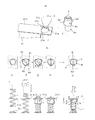
図1は本発明の第1の実施の形態を示す。図1は加熱定着装置の加圧部を示す斜視図である。
【0037】
図1において、1は筒状に形成された耐熱フィルム、3は加熱体保持部材、4は金属ステー、5は加圧力伝達部材、5aは加圧部位、6は加圧ローラ、7は圧縮ばね、8は樹脂成形されたばね押さえ部材、31は加圧ローラ支持部材、32は加圧ローラ軸受である。本実施の形態では、加圧ローラ支持部材31に形成された上方に開口を有する切り欠き部の下端に加圧ローラ軸受32を嵌合させ、その上に加熱体保持部材3を嵌合させ、さらに加圧力伝達部材5を該きり欠き部に嵌合させている。
【0038】
加熱体はセラミック基材の一方の面(本実施の形態では加圧ローラ側)に発熱体が形成されているが、他方の面あるいは両面に発熱体を設けたものであっても良い。
【0039】
図1に示すように、圧縮ばね7で加圧力伝達部材5の加圧部位5aを加圧することによって、金属ステー4と加熱体保持部材3を介して加熱体2が加圧ローラ6に圧接可能な構成になっている。
【0040】
加圧ローラ支持部材31は、上部にフランジ部(規制部)31Aが形成され、フランジ部31Aに後述する孔31aが形成されている。
【0041】
次に、圧縮ばね7とその上端を支持するばね押さえ部材8の組み立て方法とその特徴について説明する。
【0042】
図2(a)は加圧ローラ支持部材31のフランジ部31Aに形成された孔31aと、ばね押さえ部材8との関係を示し、図2(b)はその組み立て順を示した図である。
【0043】
孔31aは、内周部に複数の窪み部31a-1〜31a‐4が所定の間隔を有して形成されている。また、段付き状に形成された棒状のばね押さえ部材8は、大径部の外周に突起部8a〜8dが形成され、また小径部である案内棒8eの外周に圧縮ばね7が配置されていて、上端が小径部と大径部との突き当て部である段付き部に圧縮ばね7の上端が当接する。大径部の外周に形成された突起部8a〜8cは軸方向において同じレベルに形成され、また突起部(第2の突起部)8dのみが他の突起部8a〜8cよりも高いレベルに形成されている。
【0044】
図2(b)の▲1▼に示すように、圧縮ばね7は孔31aから加圧力伝達部材5の加圧部位5aに挿入され、次に▲2▼に示すように、ばね押さえ部材8がその案内棒8eを圧縮ばね7の内径部に差し込んで下方に押し込まれる。
【0045】
ばね押さえ部材8の外周に形成された突起部8a〜8dの位相角度に合わせて孔31aの複数の窪み部31a-1〜31a-4が形成されていて、▲3▼に示すように、複数の突起部8a〜8dが複数の窪み部31a-1〜31a-4に合ったある相対的角度の時だけ、ばね押さえ部材8を押し込むと加圧ローラ支持部材31の孔31aを全ての突起部8aから8dが通過可能となっており、通過後に、ばね押さえ部材8を回転させると、▲4▼に示すように、突起8a、8b、8cが孔31aの窪み部間に当接することによって、ばね押さえ部材8が孔31aを通過できなくなり、圧縮ばね7のばね力を支持することが可能となる。その際、突起部8dのみが隣の窪み部31a-3に嵌り込み、ばね押さえ部材8が若干量上方に移動するが、他の突起部8a〜8cが孔31aの窪み部間に当接するので、ばね押さえ部材8の上方移動が規制され、▲5▼に示すように、突起部8dが窪み部31a-3に係合した状態となり、押さえ部材8の回転が規制されることになる。したがって、突起部8dは回転止めのための突起であって、ばね押さえ8の孔に対する回転止めの機能をなす。
【0046】
以下、本実施の形態の改善点を説明する。
【0047】
第1の改善点は組み立て性が改善されることである。本実施の形態のような構成にすることによって、図8のようにばねを曲げることなく真っ直ぐ圧縮ばね7とばね押さえ部材8を組み立てることが可能となるため、圧縮ばね7の荷重が大きい場合でも自由長が長い場合でも組み立て性が良い。
【0048】
第2の改善点は、圧縮ばね7のばね定数を小さくすることができることである。前述の通り本実施の形態のような構成にすることによって、図8のようにばねを曲げることなく真っ直ぐに圧縮ばね7とばね押さえ部材8を組み込むことが可能となるため、巻き径に対する自由長の割合が比較的大きいばねであっても組み立てる過程でばねが座屈しにくいので、組み立て性が悪化しない。この結果、従来例よりばね定数を小さく設定することが可能となる。
【0049】
また、ばねを曲げることなく直上から真っ直ぐ圧縮ばね7とばね押さえ部材8を組み込むことが可能になったことよって、圧縮ばね7の内部に案内棒8eを設けることが可能となる。このように案内棒8eを設けることによって、巻き径に対する自由長の割合を大きくしても座屈による荷重の損失を受けにくいため、従来例よりばね定数を小さく設定することが可能となる。この結果、安定した加圧力を得られ加熱定着装置の定着性を安定させることができる。
【0050】
第3の改善点は、ばね押さえ部材8が樹脂化できることである。図2の通り、加圧ローラ支持部材31の孔31aと圧縮ばね7の巻き外径の差を組み立て可能な範囲でできるだけ小さくすることによって、図2の▲5▼に示すように、ばね押さえ部材8が圧縮ばね7からの作用点Aと、加圧ローラ支持部材31のフランジ部31Aからの作用点Bを作用力の方向Cから見たとき非常に近くすることができる。
【0051】
この結果、図示寸法D(ばね押さえ部材8の段付き部から突起部8a〜8cの上端までの距離)を十分大きくすれば、圧縮ばね7の作用力はばね押さえ部材8に対して、図示Eの方向の曲げ応力でなはく、図示Fの方向の圧縮応力として作用することになるため、金属でなく樹脂であっても必要な剛性を持たせることができる。
【0052】
更に、従来例のように、ばね押さえ部材8が金属であると棒形状は成形しにくいが、本実施の形態のようにばね押さえ部材8が樹脂であると案内棒8eを成形することも容易である。
【0053】
以上、説明した通り本実施の形態によれば、簡素で安価な構成で、生産時の組み立て性に優れ、量産品質の安定した高品位の加熱定着装置を実現できる。
【0054】
また、本実施の形態では、加圧ローラ支持部材31に圧縮ばね7とばね押さえ部材8を組み込む孔31aが設けられており、ばね押さえ部材8を加圧ローラ支持部材31が支持する例を示したが、図3のように、加圧ローラ支持部材31に対して別体として固定されたばね押さえ支持部材(規制部)33に、圧縮ばねとばね押さえ部材8を組み込む孔33aを設け、ばね押さえ部材8をばね押さえ支持部材33が支持する構成であっても同様の効果が得られる。なお、ばね押さえ支持部材33を一端側を加圧ローラ支持部材31の係合溝31Bに係合させ、他端側を加圧ローラ支持部材31の上部フランジ部31Aの下面に当接した状態で、図2(b)に示す手順で圧縮ばね7とばね押さえ部材8をばね押さえ支持部材31に装着する。
【0055】
(第2の実施の形態)
図4は本発明の第2の実施の形態を示す。図4は加熱定着装置の加圧部を示す斜視図である。
【0056】
図4において、1は耐熱フィルム、3は加熱体保持部材、4は金属ステー、15は加圧力伝達部材、15aは加圧部位、6は加圧ローラ、17は圧縮ばね、18は樹脂成形されたばね押さえ部材、19は加圧板、31は加圧ローラ支持部材、32は加圧ローラ軸受である。
【0057】
図1に示す実施の形態では、加圧ローラの上方位置にばね押さえ部材を位置させているが、本実施の形態では加圧ローラの真上からずれた位置にばね押さえ部材18を設けている。なお、加圧ローラ支持部材31の上面フランジ部(規制部)31Aに設けた孔31aにばね押さえ部材18を装着する構成は第1の実施の形態と同様である。
【0058】
そして、本実施の形態では、加圧板19を加圧力伝達部材15の上面の加圧部位15aに載せてその一端側を加圧ローラ支持部材31の係合溝31Bに係合させることにより加圧板19を回動自在とし、加圧板19の自由端側にばね押さえ部材18の下端を当接させている。
【0059】
図4に示すように、本実施の形態において、加圧板19は係合溝31Bとの係合部を支点19aとし、ばね押さえ部材18の下端が当接する位置を力点19bとし、さらに加圧力伝達部材の加圧部位15aとの当接位置を作用点19cとした「てこ」として作用させており、圧縮ばね17によって加圧板19を付勢し、加圧板19を介して加圧力伝達部材15の加圧部位15aを加圧することによって、金属ステー4と加熱体保持部材3を介して加熱体2が加圧ローラ6に圧接可能な構成になっている。
【0060】
加圧板19を「てこ」として利用することによって、加圧部位における加圧力を一定にする前提であっても、ばね手段の荷重をレバー比の割合で軽減することが可能となる。
【0061】
また、本実施の形態では従来例のようにばねを加圧力伝達部材15の直上に設ける必要がないため、加圧力伝達部材を上方から組み込むことが可能なままで、圧縮ばね17の上端を押さえる機能を加圧ローラ支持部材31に形成することが容易になる。
【0062】
また、ばね17の荷重がレバー比の割合で軽減されていることによって、組み立て作業が非常に容易になると同時に、加圧ローラ支持部材31におけるばね押さえ部材18の装着部位周辺も過度に剛性を強化する必要はない等のメリットもある。
【0063】
以上のように、加圧板19を「てこ」として利用する本実施の形態における加熱定着装置であっても、第1の実施の形態と同様に、組み立て性の向上、圧縮ばね17のばね定数の低減、ばね押さえ部材18の樹脂化という3つの改善が可能である。
【0064】
したがって、本実施の形態においても、簡素で安価な構成で生産時の組み立て性に優れ、量産品質の安定した高品位の加熱定着装置を実現できる。
【0065】
【発明の効果】
以上説明したように、本発明によれば、従来例と比べて、組み立て性の向上、圧縮ばねのばね定数の低減、ばね押さえ部材の樹脂化という3つの改善が実現できる。この結果、簡素で安価な構成で生産時の組み立て性に優れ、量産品質の安定した高品位の加熱定着装置を実現できるため、その発明の効果は大きい。
【図面の簡単な説明】
【図1】本発明の第1の実施の形態を示す加熱定着装置における加圧部の斜視図
【図2】図1の要部を示し、(a)はばね押さえ部材と孔との関係を示す分解斜視図、(b)はばねさえ部材の取り付け手順を示す図
【図3】第1の実施の形態の変形例を示す加熱定着装置の加圧部の斜視図
【図4】本発明の第2の実施の形態を示す加熱定着装置における加圧部の斜視図
【図5】従来の画像形成装置の概略断面図
【図6】従来の加熱定着装置の断面図
【図7】従来の加熱定着装置の加圧部の斜視図
【図8】(a)(b)は図7のばね押さえ部材の組み立て方法を示す図
【図9】(a)は図7の圧縮ばねの状態を示し、(b)は(a)の改善策を示す図
【符号の説明】
1…耐熱フィルム
3…加熱体保持部材
4…金属ステー
5…加圧力伝達部材
6…加圧ローラ
7…圧縮ばね
8…ばね押さえ部材
31…加圧ローラ支持部材
32…加圧ローラ軸受[0001]
BACKGROUND OF THE INVENTION
The present invention relates to a fixing device for an image forming apparatus using an electrophotographic process, such as a copying machine, a laser printer, and a facsimile machine.
[0002]
[Prior art]
A conventional image forming apparatus using electrophotography is configured as shown in FIG. 5, for example. In FIG. 5, 201 is a photosensitive drum, 202 is a charging roller, 203 is a laser exposure device, 204 is a reflecting mirror, 205 is a developing sleeve, 206 is toner, 207 is a toner container, 208 is a transfer roller, and 209 is a recording medium. , A cleaning blade, 211 a waste toner container, 212 a fixing device, 213 a paper cassette, 214 a paper feed roller, 215 a separation pad, and 216 a high voltage power source.
[0003]
The
[0004]
The
[0005]
The
[0006]
The visualized toner image on the
[0007]
Conventionally, as the
[0008]
However, such a film heating method generates a large offset force on the endless belt-like film. As a countermeasure, the endless film disclosed in Japanese Patent Application Laid-Open Nos. 04-44057 and 04-44077 is driven with sufficient margin to reduce the driving force and reduce the driving torque. It has become.
[0009]
An example of such a film fixing device is shown in the sectional view of FIG. In FIG. 6,
[0010]
The
[0011]
The heat-resistant film 1 is a cylindrical three-layer heat-resistant film. The innermost layer is a base layer that is responsible for mechanical properties such as torsional strength and smoothness of the heat-resistant film, and is made of a resin such as polyimide, polyamideimide, PEEK, PES, or PPS. The next layer is a conductive primer layer, which is a conductive layer in which conductive particles such as carbon black are dispersed, and also serves as an adhesive for joining the third layer and the base layer. The outermost layer is the top layer and is designed to have an optimum resistance value and film thickness so as not to cause various image defects.
[0012]
[0013]
A
[0014]
The
[0015]
In such a film heating type fixing device, a heater having a low heat capacity can be used as a heating element, so that the wait time can be shortened (quick start) compared to the conventional heat roller method. In addition, since quick start is possible, preheating during non-printing operation is not necessary, and overall power saving can be achieved.
[0016]
As a configuration of the pressure unit of the heat fixing device, one shown in FIG. 7 has been proposed. In FIG. 7, 1 is a heat resistant film, 3 is a heating body holding member, and 4 is a metal stay.
[0017]
As shown in FIG. 7, the
[0018]
The
[0019]
However, when the
[0020]
Further, the
[0021]
[Problems to be solved by the invention]
However, the heat fixing apparatus shown in FIG. 7 has the following problems.
[0022]
The first problem is that the assembling property of the
[0023]
Further, as shown in FIG. 8A, the
[0024]
The second problem is that the spring constant of the
[0025]
When considering the hardness of the pressure roller, the load of the compression spring, and the variation in the dimensional accuracy of each part during mass production, the smaller the spring constant of the
[0026]
However, if the spring constant is too small, the free length before assembling becomes long as a result, and the compression spring is buckled during the assembling process, further aggravating the problem of poor assembling ability.
[0027]
Further, when the free length becomes long as a result of reducing the spring constant, the loss of spring force due to buckling often becomes a problem. FIG. 9 (a) is a diagram showing this state, and it is generally assumed that when the ratio of the free length to the spring winding diameter exceeds 4, loss of spring force due to buckling is likely to occur. Generally, the free length is set so as to be within the range of this condition, and the minimum spring constant is determined therefrom.
[0028]
In order to reduce the loss of the spring force due to this buckling, there is a method of providing a
[0029]
A third problem is that the
[0030]
The invention according to the present application solves the above-mentioned conventional problems, and by improving the workability at the time of assembly after realizing a simple and inexpensive configuration by resinizing the spring pressing member, the achieved heat fixing apparatus capable of extent which could not be achieved to reduce the spring constant of the compression spring in the configuration, excellent assembling property during production with a simple configuration, high quality of the constant wearing stably mass production quality Is to realize the position .
[0031]
[Means for Solving the Problems]
The present invention includes a heating body in which a heating element is formed on an elongated base material, a heating body holding member that holds the heating body, and a surface side of the heating body holding member that is opposite to the surface side that holds the heating body. A metal stay provided in parallel with the longitudinal direction of the heating body, a cylindrical film arranged so that an inner peripheral surface rotates while being in contact with the heating body, and the heating body via the film A pressure roller that forms a fixing nip portion, a pressure roller support member that rotatably supports both ends of the pressure roller, and both longitudinal ends of the metal stay so that pressure is applied to the fixing nip portion A compression spring that urges each of the pressure spring, a part of the pressure roller support member, or a fixed end with respect to the pressure roller support member. And a regulation section for regulating The recording material is heated while nipping and transporting the recording material at the fixing nip portion, which is pressurized by the force of the compression spring provided between the metal stay and the regulating portion, and the toner image on the recording material is heated and fixed on the recording material. In the fixing device, the compression spring has a rod-shaped spring pressing member made of resin that holds the end opposite to the metal stay side end of the compression spring, and the spring pressing member has a plurality of protrusions on the outer periphery thereof. The restricting portion is provided with holes having a plurality of depressions at the same phase as the plurality of protrusions of the spring retainer member, and the protrusion of the spring retainer member and the restricting portion. The spring pressing member is pushed into the hole against the repulsive force of the compression spring until the protrusion passes through the hole with the phase of the hollow portion being adjusted, and then the spring pressing member is rotated. Let the spring retainer part When the force that pushes in is loosened, the retraction force of the compression spring causes the protrusion of the spring pressing member to abut the portion where the recess of the restricting portion does not exist, and the attachment in a state where the compression spring is compressed is completed der is, and the outer periphery of the spring pressing member than the protrusion and the second protrusion is provided on said spring retainer member mounting direction upstream side, the spring rotates the said spring pressing member In the state where the pressing force of the pressing member is loosened, and the protruding portion of the spring pressing member hits the portion of the restricting portion that does not have the hollow portion due to the repulsive force of the compression spring, the second protruding portion is the restricting portion. characterized Rukoto such a rotation restriction of the spring pressing member by engaging the said recess.
[0034]
By adopting the configuration of the present invention, it is possible to assemble a straight compression spring and a spring pressing member without bending the spring as in the prior art, so that the assembly becomes easy and a guide rod is provided inside the compression spring. This makes it possible to provide the necessary rigidity even with resin instead of metal. As a result, excellent assembling property when produced in a simple and inexpensive configuration, it is possible to realize stable high-quality Fixing device production quality.
[0035]
DETAILED DESCRIPTION OF THE INVENTION
Hereinafter, embodiments of the present invention will be described. In the description of the embodiments of the present invention, the entire configuration and printing operations from paper feeding to image formation, fixing, and paper ejection are the same as in the conventional example. Only the pressure part of the heat fixing device, which is a feature of the present invention, will be described.
[0036]
(First embodiment)
FIG. 1 shows a first embodiment of the present invention. FIG. 1 is a perspective view showing a pressure portion of the heat fixing device.
[0037]
In FIG. 1, 1 is a heat-resistant film formed in a cylindrical shape, 3 is a heating body holding member, 4 is a metal stay, 5 is a pressure transmission member, 5a is a pressurizing part, 6 is a pressure roller, and 7 is a compression spring. , 8 is a resin-made spring pressing member, 31 is a pressure roller support member, and 32 is a pressure roller bearing. In the present embodiment, the
[0038]
The heating element has a heating element formed on one side of the ceramic substrate (in this embodiment, the pressure roller side), but it may be provided with a heating element on the other side or both sides.
[0039]
As shown in FIG. 1, the
[0040]
The pressure
[0041]
Next, a method for assembling the
[0042]
2A shows the relationship between the
[0043]
In the
[0044]
As shown in (1) of FIG. 2 (b), the
[0045]
A plurality of
[0046]
Hereinafter, improvement points of the present embodiment will be described.
[0047]
The first improvement is that the assemblability is improved. By adopting the configuration as in the present embodiment, it becomes possible to assemble the
[0048]
A second improvement is that the spring constant of the
[0049]
Further, since it becomes possible to incorporate the
[0050]
A third improvement is that the
[0051]
As a result, if the illustrated dimension D (the distance from the stepped portion of the
[0052]
Further, as in the conventional example, if the
[0053]
As described above, according to the present embodiment, it is possible to realize a high-quality heat fixing device having a simple and inexpensive configuration, excellent in assembling at the time of production, and having stable mass production quality.
[0054]
Further, in the present embodiment, the
[0055]
(Second Embodiment)
FIG. 4 shows a second embodiment of the present invention. FIG. 4 is a perspective view showing a pressure unit of the heat fixing device.
[0056]
In FIG. 4, 1 is a heat resistant film, 3 is a heating member holding member, 4 is a metal stay, 15 is a pressure transmission member, 15a is a pressurizing part, 6 is a pressure roller, 17 is a compression spring, and 18 is resin-molded. A spring pressing member, 19 is a pressure plate, 31 is a pressure roller support member, and 32 is a pressure roller bearing.
[0057]
In the embodiment shown in FIG. 1, the spring pressing member is positioned above the pressure roller, but in this embodiment, the
[0058]
In the present embodiment, the
[0059]
As shown in FIG. 4, in the present embodiment, the
[0060]
By using the
[0061]
Further, in the present embodiment, unlike the conventional example, since it is not necessary to provide a spring directly above the pressure transmission member 15, the upper end of the compression spring 17 is pressed while the pressure transmission member can be incorporated from above. It becomes easy to form the function on the pressure
[0062]
Further, since the load of the spring 17 is reduced by the ratio of the lever ratio, the assembling operation becomes very easy, and at the same time, the rigidity of the area around the pressure
[0063]
As described above, even in the heating and fixing device in the present embodiment that uses the
[0064]
Therefore, also in the present embodiment, it is possible to realize a high-quality heat fixing device that has a simple and inexpensive configuration, is excellent in assembling during production, and has stable mass production quality.
[0065]
【The invention's effect】
As described above, according to the present invention, compared with the conventional example, three improvements, that is, improved assembly, reduction of the spring constant of the compression spring, and resinization of the spring pressing member can be realized. As a result, it is possible to realize a high-quality heat-fixing device having a simple and inexpensive configuration that is excellent in assembling at the time of production and has stable mass production quality.
[Brief description of the drawings]
FIG. 1 is a perspective view of a pressure unit in a heat fixing apparatus showing a first embodiment of the present invention. FIG. 2 shows a main part of FIG. 1, and (a) shows a relationship between a spring pressing member and a hole. FIG. 3B is an exploded perspective view showing a procedure for attaching a spring even member. FIG. 3 is a perspective view of a pressure unit of a heat fixing apparatus showing a modification of the first embodiment. FIG. 5 is a schematic cross-sectional view of a conventional image forming apparatus. FIG. 6 is a cross-sectional view of a conventional heat-fixing apparatus. FIG. 7 is a conventional heat-fixing apparatus. FIGS. 8A and 8B are views showing a method of assembling the spring pressing member of FIG. 7. FIG. 9A is a state of the compression spring of FIG. (B) is a diagram showing the improvement measures of (a) [Explanation of symbols]
DESCRIPTION OF SYMBOLS 1 ... Heat-
Claims (1)
前記圧縮ばねの前記金属ステー側端部とは反対側端部を押える樹脂製で棒状のばね押え部材を有し、前記ばね押え部材にはその外周に複数の突起部が設けられており、前記規制部には前記ばね押え部材の複数の前記突起部とそれぞれ同位相の位置に複数の窪み部を有する孔が設けられており、前記ばね押え部材の前記突起部と前記規制部の前記窪み部の位相を合わせた状態で前記突起部が前記孔を通過するまで前記ばね押え部材を前記圧縮ばねの反発力に抗して前記孔に押し込み、その後、前記ばね押え部材を回動させて前記ばね押え部材を押し込む力を緩めると、前記圧縮ばねの反発力で前記ばね押え部材の前記突起部が前記規制部の前記窪み部がない部分に突き当たり前記圧縮ばねが圧縮された状態での取り付けが完了する構造であり、且つ前記ばね押え部材の外周には、前記突起部よりも前記ばね押え部材装着方向上流側に第2の突起部が設けられており、前記ばね押え部材を回動させて前記ばね押え部材を押し込む力を緩め、前記圧縮ばねの反発力で前記ばね押え部材の前記突起部が前記規制部の前記窪み部がない部分に突き当たった状態で、前記第2の突起部が前記規制部の前記窪み部に係合することにより前記ばね押え部材の回動規制となることを特徴とする定着装置。A heating element in which a heating element is formed on an elongated base material, a heating element holding member that holds the heating element, and the heating element on a surface opposite to the surface side of the heating element holding member that holds the heating element A metal stay provided in parallel with the longitudinal direction of the plate, a cylindrical film arranged so that an inner peripheral surface rotates while contacting the heating body, and the heating body and the fixing nip portion through the film. A pressure roller to be formed, a pressure roller support member that rotatably supports both ends of the pressure roller, and both end portions in the longitudinal direction of the metal stay are biased so that pressure is applied to the fixing nip portion. A compression spring, and a part of the pressure roller support member or the pressure roller support member fixedly arranged with respect to the pressure roller support member, for restricting an end of the compression spring opposite to the end of the metal stay A regulating part, and the metal A fixing device for heating and fixing a toner image on the recording material to the recording material by holding and conveying the recording material at the fixing nip portion which is pressurized by the force of the compression spring provided between the tape and the regulating portion In
The compression spring has a resin-like rod-like spring pressing member that holds the end opposite to the metal stay side end, and the spring pressing member has a plurality of protrusions on its outer periphery, The restricting portion is provided with holes having a plurality of recess portions at the same phase as the plurality of protrusion portions of the spring pressing member, and the protrusion portion of the spring pressing member and the recess portion of the restricting portion. The spring pressing member is pushed into the hole against the repulsive force of the compression spring until the protruding portion passes through the hole in a state in which the phases are aligned, and then the spring pressing member is rotated to rotate the spring. When the force for pushing the presser member is loosened, the rebound force of the compression spring causes the protrusion of the spring presser member to abut the portion where the recess of the restricting part does not exist, and the installation in the state where the compression spring is compressed is completed. structure der that is, On the outer periphery of the spring pressing member, a second protrusion is provided on the upstream side of the protrusion in the mounting direction of the spring pressing member, and the spring pressing member is rotated to push the spring pressing member. The second projecting portion is the recessed portion of the restricting portion in a state in which the force is released and the projecting portion of the spring pressing member abuts on a portion of the restricting portion that does not have the recessed portion due to the repulsive force of the compression spring. the fixing device according to claim Rukoto such a rotation restriction of the spring pressing member by engaging the.
Priority Applications (2)
| Application Number | Priority Date | Filing Date | Title |
|---|---|---|---|
| JP2001067157A JP4672888B2 (en) | 2001-03-09 | 2001-03-09 | Fixing device |
| US10/091,283 US6731901B2 (en) | 2001-03-09 | 2002-03-06 | Image heating apparatus |
Applications Claiming Priority (1)
| Application Number | Priority Date | Filing Date | Title |
|---|---|---|---|
| JP2001067157A JP4672888B2 (en) | 2001-03-09 | 2001-03-09 | Fixing device |
Publications (3)
| Publication Number | Publication Date |
|---|---|
| JP2002268414A JP2002268414A (en) | 2002-09-18 |
| JP2002268414A5 JP2002268414A5 (en) | 2008-04-24 |
| JP4672888B2 true JP4672888B2 (en) | 2011-04-20 |
Family
ID=18925549
Family Applications (1)
| Application Number | Title | Priority Date | Filing Date |
|---|---|---|---|
| JP2001067157A Expired - Fee Related JP4672888B2 (en) | 2001-03-09 | 2001-03-09 | Fixing device |
Country Status (2)
| Country | Link |
|---|---|
| US (1) | US6731901B2 (en) |
| JP (1) | JP4672888B2 (en) |
Families Citing this family (14)
| Publication number | Priority date | Publication date | Assignee | Title |
|---|---|---|---|---|
| KR100516165B1 (en) * | 2003-09-24 | 2005-09-22 | 삼성전자주식회사 | Fusing apparatus for image forming apparatus |
| US20060067752A1 (en) * | 2004-09-29 | 2006-03-30 | Jichang Cao | Belt fuser assembly with heated backup roll in an electrophotographic imaging device |
| US7637499B2 (en) * | 2006-02-09 | 2009-12-29 | Canon Kabushiki Kaisha | Sheet feeding apparatus and recording apparatus |
| TWI301451B (en) * | 2006-06-28 | 2008-10-01 | Lite On Technology Corp | A heating and fixing device for fixing toner particles |
| JP2008058563A (en) * | 2006-08-31 | 2008-03-13 | Ricoh Co Ltd | Pressing member, fixing device using same, and image forming apparatus |
| US7899380B2 (en) * | 2007-02-20 | 2011-03-01 | Konica Minolta Business Technologies, Inc. | Image forming apparatus having fixing device and controller to execute a cleaning mode |
| KR100864716B1 (en) * | 2007-10-04 | 2008-10-23 | 삼성전자주식회사 | Fusing device and image forming apparatus having the same |
| JP5263146B2 (en) * | 2009-12-28 | 2013-08-14 | ブラザー工業株式会社 | Fixing device |
| JP5541734B2 (en) | 2010-12-14 | 2014-07-09 | キヤノン株式会社 | Image heating device |
| JP5523524B2 (en) | 2012-09-06 | 2014-06-18 | キヤノン株式会社 | Image forming apparatus |
| JP6173245B2 (en) * | 2014-03-20 | 2017-08-02 | 京セラドキュメントソリューションズ株式会社 | Roller support mechanism, roller unit, fixing device |
| JP6525610B2 (en) * | 2015-01-29 | 2019-06-05 | キヤノン株式会社 | Fixing device and recording material conveyance device |
| US9851669B2 (en) * | 2015-01-29 | 2017-12-26 | Canon Kabushiki Kaisha | Fixing device |
| JP2022029590A (en) * | 2020-08-05 | 2022-02-18 | キヤノン株式会社 | Heating device and image forming apparatus |
Citations (4)
| Publication number | Priority date | Publication date | Assignee | Title |
|---|---|---|---|---|
| JPH0444080A (en) * | 1990-06-11 | 1992-02-13 | Canon Inc | Heating device |
| JPH04204981A (en) * | 1990-11-30 | 1992-07-27 | Canon Inc | Heater |
| JPH08305252A (en) * | 1995-04-28 | 1996-11-22 | Canon Inc | Process cartridge and image forming device |
| JPH11153937A (en) * | 1997-11-20 | 1999-06-08 | Canon Inc | Process cartridge and electrophotographic image forming device |
Family Cites Families (15)
| Publication number | Priority date | Publication date | Assignee | Title |
|---|---|---|---|---|
| US4802439A (en) * | 1986-03-06 | 1989-02-07 | Sharp Kabushiki Kaisha | Pressure applying mechanism for fixing rollers of a copying apparatus |
| JP2516886B2 (en) | 1987-06-16 | 1996-07-24 | キヤノン株式会社 | Image heating device |
| EP0295901B1 (en) | 1987-06-16 | 1995-12-20 | Canon Kabushiki Kaisha | An image fixing apparatus |
| JP2884715B2 (en) | 1990-06-11 | 1999-04-19 | キヤノン株式会社 | Image heating device |
| US5148226A (en) | 1990-06-11 | 1992-09-15 | Canon Kabushiki Kaisha | Heating apparatus using endless film |
| DE69117806T2 (en) | 1990-06-11 | 1996-08-22 | Canon Kk | Heater with continuous film |
| JP2884714B2 (en) | 1990-06-11 | 1999-04-19 | キヤノン株式会社 | Image heating device |
| JPH0452677A (en) * | 1990-06-20 | 1992-02-20 | Fujitsu Ltd | Fixing device |
| JP3155066B2 (en) * | 1992-06-17 | 2001-04-09 | キヤノン株式会社 | Fixing device |
| JP3223628B2 (en) * | 1993-02-08 | 2001-10-29 | キヤノン株式会社 | Fixing device |
| US5532806A (en) * | 1993-04-28 | 1996-07-02 | Canon Kabushiki Kaisha | Image fixing apparatus having means for preventing temperature unevenness |
| JP3282448B2 (en) * | 1995-05-29 | 2002-05-13 | キヤノン株式会社 | Image forming device |
| JPH09212019A (en) * | 1996-01-31 | 1997-08-15 | Canon Inc | Image forming device and its fixing device |
| JP3376228B2 (en) * | 1996-12-12 | 2003-02-10 | キヤノン株式会社 | Image heating fixing device |
| US5810965A (en) * | 1997-04-07 | 1998-09-22 | Fwu; Jason | Thermal embossing/laminating system of printing machine |
-
2001
- 2001-03-09 JP JP2001067157A patent/JP4672888B2/en not_active Expired - Fee Related
-
2002
- 2002-03-06 US US10/091,283 patent/US6731901B2/en not_active Expired - Lifetime
Patent Citations (4)
| Publication number | Priority date | Publication date | Assignee | Title |
|---|---|---|---|---|
| JPH0444080A (en) * | 1990-06-11 | 1992-02-13 | Canon Inc | Heating device |
| JPH04204981A (en) * | 1990-11-30 | 1992-07-27 | Canon Inc | Heater |
| JPH08305252A (en) * | 1995-04-28 | 1996-11-22 | Canon Inc | Process cartridge and image forming device |
| JPH11153937A (en) * | 1997-11-20 | 1999-06-08 | Canon Inc | Process cartridge and electrophotographic image forming device |
Also Published As
| Publication number | Publication date |
|---|---|
| US6731901B2 (en) | 2004-05-04 |
| JP2002268414A (en) | 2002-09-18 |
| US20020141796A1 (en) | 2002-10-03 |
Similar Documents
| Publication | Publication Date | Title |
|---|---|---|
| US9501011B2 (en) | Fixing device and image forming apparatus including same | |
| US8655211B2 (en) | Fixing device and image forming apparatus incorporating same | |
| US8676104B2 (en) | Fixing device and image forming apparatus | |
| US9429891B2 (en) | Fixing device and image forming apparatus | |
| JP4672888B2 (en) | Fixing device | |
| US9791813B2 (en) | Fixing device and image forming apparatus | |
| US6674979B2 (en) | Image forming apparatus enabled to optimize transfer medium slack between transferring and fixing portions | |
| US11994815B2 (en) | Heating apparatus and image forming apparatus | |
| KR100738542B1 (en) | Fixing device having pressure member and image forming apparatus including the same | |
| US8515326B2 (en) | Image heating apparatus having stably positioned heating unit | |
| JP4035426B2 (en) | Fixing device | |
| JP2007178828A (en) | Image heating device | |
| JP5991171B2 (en) | Fixing device and image forming apparatus having the same | |
| JP4497735B2 (en) | Fixing device | |
| JP4566428B2 (en) | Fixing device | |
| JP2003122147A (en) | Thermal fixing device and image forming device | |
| JP7127496B2 (en) | Fixing device and image forming device | |
| JP2008250091A (en) | Fixing device and image forming apparatus | |
| JP2024067575A (en) | Fixing device | |
| JP2023049702A (en) | Fixing device and image forming apparatus | |
| JP2005157172A (en) | Heating device and image forming apparatus | |
| JP2002181630A (en) | Temperature detector, heat-fixing device and image forming device | |
| JP2004163465A (en) | Fixing device | |
| JP2001356624A (en) | Image heating device and image forming device |
Legal Events
| Date | Code | Title | Description |
|---|---|---|---|
| A521 | Written amendment |
Free format text: JAPANESE INTERMEDIATE CODE: A523 Effective date: 20080307 |
|
| A621 | Written request for application examination |
Free format text: JAPANESE INTERMEDIATE CODE: A621 Effective date: 20080307 |
|
| RD01 | Notification of change of attorney |
Free format text: JAPANESE INTERMEDIATE CODE: A7421 Effective date: 20081031 |
|
| RD04 | Notification of resignation of power of attorney |
Free format text: JAPANESE INTERMEDIATE CODE: A7424 Effective date: 20100201 |
|
| RD01 | Notification of change of attorney |
Free format text: JAPANESE INTERMEDIATE CODE: A7421 Effective date: 20100630 |
|
| A977 | Report on retrieval |
Free format text: JAPANESE INTERMEDIATE CODE: A971007 Effective date: 20101021 |
|
| A131 | Notification of reasons for refusal |
Free format text: JAPANESE INTERMEDIATE CODE: A131 Effective date: 20101026 |
|
| A521 | Written amendment |
Free format text: JAPANESE INTERMEDIATE CODE: A523 Effective date: 20101221 |
|
| TRDD | Decision of grant or rejection written | ||
| A01 | Written decision to grant a patent or to grant a registration (utility model) |
Free format text: JAPANESE INTERMEDIATE CODE: A01 Effective date: 20110118 |
|
| A01 | Written decision to grant a patent or to grant a registration (utility model) |
Free format text: JAPANESE INTERMEDIATE CODE: A01 |
|
| A61 | First payment of annual fees (during grant procedure) |
Free format text: JAPANESE INTERMEDIATE CODE: A61 Effective date: 20110120 |
|
| R150 | Certificate of patent or registration of utility model |
Free format text: JAPANESE INTERMEDIATE CODE: R150 |
|
| FPAY | Renewal fee payment (event date is renewal date of database) |
Free format text: PAYMENT UNTIL: 20140128 Year of fee payment: 3 |
|
| LAPS | Cancellation because of no payment of annual fees |