JP4671512B2 - Nonvolatile semiconductor memory - Google Patents
Nonvolatile semiconductor memory Download PDFInfo
- Publication number
- JP4671512B2 JP4671512B2 JP2001026030A JP2001026030A JP4671512B2 JP 4671512 B2 JP4671512 B2 JP 4671512B2 JP 2001026030 A JP2001026030 A JP 2001026030A JP 2001026030 A JP2001026030 A JP 2001026030A JP 4671512 B2 JP4671512 B2 JP 4671512B2
- Authority
- JP
- Japan
- Prior art keywords
- signal
- register
- memory
- timing
- memory array
- Prior art date
- Legal status (The legal status is an assumption and is not a legal conclusion. Google has not performed a legal analysis and makes no representation as to the accuracy of the status listed.)
- Expired - Fee Related
Links
Images


Classifications
-
- G—PHYSICS
- G11—INFORMATION STORAGE
- G11C—STATIC STORES
- G11C16/00—Erasable programmable read-only memories
- G11C16/02—Erasable programmable read-only memories electrically programmable
- G11C16/06—Auxiliary circuits, e.g. for writing into memory
-
- G—PHYSICS
- G11—INFORMATION STORAGE
- G11C—STATIC STORES
- G11C29/00—Checking stores for correct operation ; Subsequent repair; Testing stores during standby or offline operation
- G11C29/70—Masking faults in memories by using spares or by reconfiguring
- G11C29/78—Masking faults in memories by using spares or by reconfiguring using programmable devices
- G11C29/84—Masking faults in memories by using spares or by reconfiguring using programmable devices with improved access time or stability
- G11C29/846—Masking faults in memories by using spares or by reconfiguring using programmable devices with improved access time or stability by choosing redundant lines at an output stage
-
- G—PHYSICS
- G11—INFORMATION STORAGE
- G11C—STATIC STORES
- G11C16/00—Erasable programmable read-only memories
- G11C16/02—Erasable programmable read-only memories electrically programmable
- G11C16/06—Auxiliary circuits, e.g. for writing into memory
- G11C16/22—Safety or protection circuits preventing unauthorised or accidental access to memory cells
-
- G—PHYSICS
- G11—INFORMATION STORAGE
- G11C—STATIC STORES
- G11C16/00—Erasable programmable read-only memories
- G11C16/02—Erasable programmable read-only memories electrically programmable
- G11C16/04—Erasable programmable read-only memories electrically programmable using variable threshold transistors, e.g. FAMOS
- G11C16/0408—Erasable programmable read-only memories electrically programmable using variable threshold transistors, e.g. FAMOS comprising cells containing floating gate transistors
- G11C16/0416—Erasable programmable read-only memories electrically programmable using variable threshold transistors, e.g. FAMOS comprising cells containing floating gate transistors comprising cells containing a single floating gate transistor and no select transistor, e.g. UV EPROM
-
- G—PHYSICS
- G11—INFORMATION STORAGE
- G11C—STATIC STORES
- G11C16/00—Erasable programmable read-only memories
- G11C16/02—Erasable programmable read-only memories electrically programmable
- G11C16/06—Auxiliary circuits, e.g. for writing into memory
- G11C16/10—Programming or data input circuits
Landscapes
- Engineering & Computer Science (AREA)
- Computer Security & Cryptography (AREA)
- Read Only Memory (AREA)
- For Increasing The Reliability Of Semiconductor Memories (AREA)
Description
【0001】
【発明の属する技術分野】
この発明は、不揮発性トランジスタを用いた不揮発性半導体メモリおよびその自動消去/自動書き込み方法に関するものである。
【0002】
【従来の技術】
図26は従来の不揮発性半導体メモリの全体構成を示すブロック図であり、図において、1001は不揮発性半導体メモリ、1002はメモリ/メモリデコーダ、1003はチャージポンプ、1004はMCUなどを含む専用制御回路である。
【0003】
なお、メモリ/メモリデコーダ1002はメモリブロックとメモリデコーダをまとめたもので、メモリブロックには各種の集積度を有する複数個の小メモリブロック、センスアンプ/書き込み回路、セレクタ回路などが含まれ、メモリデコーダにはロウ・アドレスラッチ、コラム・アドレス入力バッファラッチ、ロウ/コラム・アドレスプリデコーダなどが含まれる(図示しない)。また、チャージポンプ1003は負電圧/正電圧チャージポンプおよび読み出しポンプにより構成される(図示しない)。詳細および動作説明については後述の実施の形態を参考にされたい。
【0004】
このように、従来の不揮発性半導体メモリ1001は、自動消去/自動書き込み/データ読み出しなどのメモリ制御を、不揮発性半導体メモリ1001内に有する専用制御回路1004を用いて実行していた。不揮発性半導体メモリ1001内に有する専用制御回路1004は、メモリの制御のみを実行する特化された回路であり、データ処理装置と不揮発性半導体メモリを同一チップ内に有するLSIなどは、この専用制御回路1004の大きさが無視できない回路規模の大きさになってきている。
【0005】
また、国際公開WO99/01824には、EEPROM内蔵の半導体装置において、EEPROMを制御するために必要な制御信号のそれぞれを、専用制御回路では無く、フリップフロップで構成されるレジスタブロックによって制御する方法が記されている。しかし、近年のマイクロコントローラに内蔵される不揮発性半導体メモリは、消去/書き込みに必要な電圧を発生させるチャージポンプをチップ内部に保有するなど、制御する信号の種類が多く、また消去/書き込み以外の動作モードも複数存在するため、このWO99/01824に示されているフリップフロップで構成されるレジスタブロックによって、複数個の制御信号を同時にアクティブにさせたり、また動作モード毎に異なった組み合わせの制御信号を同タイミングでアクティブにさせて制御することはできない。
【0006】
また、従来の不揮発性半導体メモリは、複数のメモリセルが行列状に配置されたメモリアレイで構成されたメモリブロック中のメモリアレイをダミーメモリアレイと置換することができる。この置換処理は、不揮発性半導体メモリ内にあるFUSE回路をレーザによって切断して行っている。
【0007】
【発明が解決しようとする課題】
従来の不揮発性半導体メモリおよびその自動消去/自動書き込み方法は以上のように構成されているので、当該メモリ内に有する専用制御回路が、データ処理装置と不揮発性半導体メモリを同一チップ内に有するLSIの回路規模の増大をまねいているという課題があった。
【0008】
また、従来の不揮発性半導体メモリ内に有するFUSE回路は、レーザによって切断した後に切断が上手くいっているか否かの確認を直接できないという課題があった。
【0009】
さらに、従来の不揮発性半導体メモリは、複数のメモリセルが行列状に配置されたメモリアレイで構成されたメモリブロック中のメモリアレイをダミーメモリアレイと置換するにはFUSE回路をレーザでトリミング処理するしか方法が無く、擬似的に置換処理する方法は無かった。
【0010】
この発明は上記のような課題を解決するためになされたもので、不揮発性半導体メモリと同一チップ内にあるデータ処理装置を用いて、不揮発性半導体メモリの自動消去/自動書き込み/データ読み出しなどを実行することで、不揮発性半導体メモリ内に有する専用制御回路を削除し、チップ全体の回路規模の縮小できる不揮発性半導体メモリおよびその自動消去/自動書き込み方法を得ることを目的とする。
【0011】
また、不揮発性半導体メモリ内に擬似的なレジスタを設け、レジスタ値を設定することによって、複数のメモリセルが行列状に配置されたメモリセルで構成されたメモリブロック中のメモリアレイをダミーメモリアレイと置換することができる不揮発性半導体メモリを得ることを目的とする。
【0012】
【課題を解決するための手段】
この発明に係る不揮発性半導体メモリは、不揮発性トランジスタからなる複数のメモリセルが行列状に配置されたメモリアレイで構成されたメモリブロックと、メモリアレイ内の不揮発性トランジスタのデータを、消去/書き込み/読み出しするために必要なメモリデコーダと、メモリアレイ内の不揮発性トランジスタのデータを、消去/書き込み/読み出しするために必要なチャージポンプと、メモリデコーダとチャージポンプを制御する複数本の制御信号のそれぞれをレジスタ1ビットに割り付けたレジスタと、レジスタの結合されたデータ処理装置によってレジスタの内容を更新する手段と、当該更新する手段がレジスタの内容を更新することによって、メモリデコーダおよびチャージポンプを制御する手段とを備えたものである。
【0013】
この発明に係る不揮発性半導体メモリは、レジスタの内容を更新することによって、メモリブロックを消去する手段をさらに備えたものである。
【0014】
この発明に係る不揮発性半導体メモリは、レジスタの内容を更新することによって、メモリブロック内の不揮発性トランジスタにデータを書き込む手段をさらに備えたものである。
【0015】
この発明に係る不揮発性半導体メモリは、レジスタの内容を更新することによって、メモリブロック内の不揮発性トランジスタのデータを読み出す手段をさらに備えたものである。
【0016】
この発明に係る不揮発性半導体メモリの自動消去方法は、不揮発性トランジスタからなる複数のメモリセルが行列状に配置されたメモリアレイで構成されたメモリブロックと、メモリアレイ内の不揮発性トランジスタのデータを、消去/書き込み/読み出しするために必要なメモリデコーダと、メモリアレイ内の不揮発性トランジスタのデータを、消去/書き込み/読み出しするために必要なチャージポンプと、メモリデコーダとチャージポンプを制御する複数本の制御信号のそれぞれをレジスタ1ビットに割り付けたレジスタと、レジスタに結合されたデータ処理装置によってレジスタの内容を更新する手段とを備えた不揮発性半導体メモリにおいて、レジスタの内容を更新することによって、メモリブロックのデータを消去するものである。
【0017】
この発明に係る不揮発性半導体メモリの自動書き込み方法は、不揮発性トランジスタからなる複数のメモリセルが行列状に配置されたメモリアレイで構成されたメモリブロックと、メモリアレイ内の不揮発性トランジスタのデータを、消去/書き込み/読み出しするために必要なメモリデコーダと、メモリアレイ内の不揮発性トランジスタのデータを、消去/書き込み/読み出しするために必要なチャージポンプと、メモリデコーダとチャージポンプを制御する複数本の制御信号のそれぞれをレジスタ1ビットに割り付けたレジスタと、レジスタに結合されたデータ処理装置によってレジスタの内容を更新する手段とを備えた不揮発性半導体メモリにおいて、レジスタの内容を更新することによって、メモリブロックの不揮発性トランジスタにデータを書き込むものである。
【0018】
この発明に係る不揮発性半導体メモリは、不揮発性トランジスタからなる複数のメモリセルが行列状に配置されたメモリアレイで構成されたメモリブロックと、メモリアレイと置換することのできるダミーメモリアレイと、ダミーメモリアレイとメモリブロック内の1つのメモリアレイをトリミング処理によって置換することのできる第1の手段と、ダミーメモリアレイとメモリブロック内の1つのメモリアレイをダミーメモリアレイを含む置換回路によらず、疑似レジスタにデータをセットすることで置換することのできる第2の手段と、この第2の手段によって、第1の手段で行うメモリアレイとダミーメモリアレイの置換を行う手段とを備えるものである。
【0019】
この発明に係る不揮発性半導体メモリは、第1の手段によってダミーメモリアレイとメモリブロック内の1つのメモリアレイの置換を行う場合には、この第2の手段による置換処理が設定されている場合でも第1の手段による置換を優先させる手段をさらに備えたものである。
【0020】
この発明に係る不揮発性半導体メモリは、第1の手段によってダミーメモリアレイとメモリブロック内の1つのメモリアレイの置換を行う情報と、この第2の手段による置換処理の情報とを読み出して比較する手段をさらに備えたものである。
【0021】
この発明に係る不揮発性半導体メモリは、第2の手段による置換処理でセットされた疑似レジスタ値を不揮発性トランジスタからなるメモリセル内に書き込んだ後に読み出す手段を有し、第1の手段および第2の手段による置換処理の情報とを読み出してこれらを比較する手段をさらに備えたものである。
【0022】
【発明の実施の形態】
以下、この発明の実施の一形態を説明する。
実施の形態1.
(ブロック構成)
図1はこの発明の実施の形態1による不揮発性半導体メモリの全体構成を示すブロック図であり、この不揮発性半導体メモリを制御するデータ処理装置との関係を示している。図において、101は不揮発性半導体メモリ、1はデータ処理装置、2はレジスタ回路群(レジスタ)、3はチャージポンプ、4はメモリデコーダ、5はメモリブロックである。
【0023】
なお、この発明の実施の形態1による不揮発性半導体メモリ101は、メモリの内容を消去する自動消去モード、任意のアドレスにデータを書き込む自動書き込みモード、ロックビットにロック情報を書き込むロックビット書き込み、ロックビットの内容を読み出すロックビット読み出しモードの他に、メモリデータの内容を読み出す読み出しモードがある。
【0024】
(レジスタ回路群)
次に、図2はこの発明の実施の形態1による不揮発性半導体メモリのレジスタ回路群のブロック図であり、図において、6はポンプ/メモリデコーダ用制御信号レジスタ、7はアドレスレジスタ、8はデータレジスタ、9はデータバッファ、10はステータスレジスタ、11はシーケンス制御レジスタ、12はコンペア回路、13は疑似LTレジスタ、14はメモリデコーダ制御信号、15はチャージポンプ制御信号、16はAD(24:0)バス(更新する手段)、17はA(24:0)バス(更新する手段)、18はDDB(15:0)バス(更新する手段)、19はDB(15:0)バス(更新する手段)、137はレジスタセット信号、138はブロック選択信号、139は信号出力信号である。
【0025】
ポンプ/メモリデコーダ用制御信号レジスタ6は、ポンプとメモリデコーダを制御するための制御信号がレジスタ1ビットに割り当てられた16ビットレジスタである。DB(15:0)バス19からの入力経路と、レジスタ中に割り付けられた制御信号のうちチャージポンプ制御信号15としてチャージポンプ3へ出力される経路と、レジスタ中に割り付けられた制御信号のうちメモリデコーダ制御信号14としてメモリデコーダ4へ出力される経路がある。ポンプ/メモリデコーダ用制御信号レジスタ6へのデータのセットは、データ処理装置1から入力されるレジスタセット信号137をトリガーにDB(15:0)バス19から行われる。また、メモリデコーダ制御信号14とチャージポンプ制御信号15は、データ処理装置1から入力される信号出力信号139をトリガーにしてメモリデコーダ4とチャージポンプ3に出力される。
【0026】
アドレスレジスタ7は、自動消去、自動書き込み、ロックビット書き込み、ロックビット読み出し時などに、アクセスするブロックのアドレスを保持する。また、アドレスレジスタ7は、アドレスのインクリメント機能を持ち、自動消去の消去ベリファイ時でアドレスを消去対象となるメモリブロックの最大アドレスまでインクリメントする。アドレスレジスタ7は、AD(24:0)バス16からの入力経路、A(24:0)バス17への出力経路がある。また、アドレスレジスタ7へのデータのセットは、データ処理装置1から入力されるレジスタセット信号137をトリガーにDB(15:0)バス19から行われる。また、アドレスレジスタ7のアドレス値の読み出しは、レジスタ値読み出し信号140によってDB(15:0)バス19に読み出すこともできる。さらに、アドレス値から、ブロック選択信号138を生成して、メモリデコーダ4に出力している。
【0027】
データレジスタ8は、自動書き込み時の書き込みデータを保持したり、ロックビット読み出し時に読み出したロックビット値を保持する。DB(15:0)バス19からの入出力経路と、DDBバス18からの入出力経路がある。データレジスタ8へのデータのセットは、データ処理装置1から入力されるレジスタセット信号137をトリガーにDB(15:0)バス19から行われる。また、データレジスタ8のアドレス値の読み出しは、レジスタ値読み出し信号140によってDB(15:0)バス19に読み出すこともできる。
【0028】
データバッファ9は、メモリデータ読み出し時にDDB(15:0)バス18の値を直接DBバス19に出力する。DDB(15:0)バス18からの入力経路とDB(15:0)バス19への出力経路がある。
【0029】
ステータスレジスタ10は、自動消去、自動書き込み、ロックビット書き込み時に、消去エラーや書き込みエラー情報を保持する。DB(15:0)バス19からの入力経路がある。ステータスレジスタ10へのデータのセットは、データ処理装置1から入力されるレジスタセット信号137をトリガーにDB(15:0)バス19から行われる。また、ステータスレジスタ10のレジスタ値の読み出しは、レジスタ値読み出し信号140によって、DB(15:0)バス19に読み出すこともできる。
【0030】
シーケンス制御レジスタ11は、2ビットのレジスタである。自動消去時の、消去ベリファイ開始ビットとエラー設定ビットがある。DB(15:0)バス19からの入力経路と、レジスタ2ビットの情報はコンペア回路12に出力されている。自動消去中の消去エラー発生時には、コンペア回路12が、シーケンス制御レジスタ11のエラー設定ビットを操作する。シーケンス制御レジスタ11へのデータのセットは、データ処理装置1から入力されるレジスタセット信号137をトリガーにDB(15:0)バス19から行われる。また、シーケンス制御レジスタ11のレジスタ値の読み出しは、レジスタ値読み出し信号140によってDBバス(15:0)バス19に読み出すこともできる。
【0031】
コンペア回路12は、自動消去中の消去ベリファイ時に読み出されたメモリデータと期待値を比較する。比較した結果を元に、シーケンス制御レジスタ11の消去ベリファイ開始ビットとエラー設定ビットを書き換える。
【0032】
疑似LTレジスタ13は、擬似的にビット線を書き換える場合にデータをセットするレジスタである。メモリブロック数だけレジスタが存在する。疑似LTレジスタ13へのデータのセットは、データ処理装置1から入力されるレジスタセット信号137をトリガーにDB(15:0)バス19から行われる。また、疑似LTレジスタ13のレジスタ値の読み出しは、レジスタ値読み出し信号140によってDBバス(15:0)バス19に読み出すこともできる。さらに、疑似LTレジスタ13値は、直接メモリデコーダ4に出力されている。またさらに、メモリデコーダ4内のFUSE回路52の出力信号が、疑似レジスタ13に出力されている。FUSE回路52の出力信号値は、疑似LTレジスタ139を介してDB(15:0)バス19に出力される経路を持っている。
【0033】
次に、図3に、この発明の実施の形態1による不揮発性半導体メモリのレジスタ回路群2中の各種レジスタに割り付けられたアドレス空間を示す。以下、これを説明する。
【0034】
アドレスレジスタ7は、8ビットアドレスレジスタ(ADDRL)、8ビットアドレスレジスタ(ADDRM)、8ビットアドレスレジスタ(ADDRH)がある。これらのアドレスレジスタ(ADDRL)、アドレスレジスタ(ADDRM)、アドレスレジスタ(ADDRH)は、それぞれE0H、E1H、E2Hに割り付けられている。
【0035】
データレジスタ8は、下位8ビットデータレジスタ(DATAL)と上位8ビットデータレジスタ(DATAH)がある。データレジスタ(DATAL)とデータレジスタ(DATAH)は、E4HとE5Hに割り付けられている。
【0036】
ステータスレジスタ10は、8ビットのレジスタであり、E6Hに割り付けられている。
【0037】
ポンプ/メモリデコーダ用制御信号レジスタ1、ポンプ/メモリデコーダ用制御信号レジスタ2は、E7HとE8Hに割り付けられている。
【0038】
出力信号レジスタは、EEHに割り付けられている。出力信号レジスタに1を立てることによって、信号出力信号139がアクティブになり、ポンプ/メモリデコーダ用制御信号レジスタ1とポンプ/メモリデコーダ用制御信号レジスタ2の内容がチャージポンプ3とメモリデコーダ4に出力される。
【0039】
シーケンス制御レジスタ11は、8ビットレジスタであり、F0Hに割り付けられている。疑似LTレジスタ0は、8ビットレジスタであり、F8Hに割り付けられている。
【0040】
(レジスタ仕様)
(ポンプ/メモリデコーダ用制御信号レジスタ6)
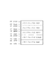
次に、図4に、ポンプ/メモリデコーダ用制御信号レジスタ6の内容を示す。16ビットのレジスタのうちb0〜b7は、ポンプ/メモリデコーダ用制御信号レジスタ6(1)である。なお、b8〜b15は、ポンプ/メモリデコーダ用制御信号レジスタ6(2)である。
【0041】
ポンプ/メモリデコーダ用制御信号レジスタ6(1)のb0は、BYTE信号に割り当てられている。この発明の実施の形態1による不揮発性半導体メモリをバイトモードでアクセスする場合には、BYTE信号に“1”がセットされる。ワードアクセス時には、“0”にセットされる。BYTE信号は、メモリデコーダ4に出力される。
【0042】
ポンプ/メモリデコーダ用制御信号レジスタ6(1)のb1は、NE信号に割り当てられている。NE信号は、この発明の実施の形態1による不揮発性半導体メモリに搭載されている負電圧ポンプを活性化させる場合に“1”がセットされる。NE信号は、チャージポンプ3に出力される。
【0043】
ポンプ/メモリデコーダ用制御信号レジスタ6(1)のb2は、PE信号に割り当てられている。PE信号は、この発明の実施の形態1による不揮発性半導体メモリに搭載されている正電圧ポンプを活性化させる場合に“1”がセットされる。PE信号は、チャージポンプ3に出力される。
【0044】
ポンプ/メモリデコーダ用制御信号レジスタ6(1)のb3は、ERS信号に割り当てられている。ERS信号は、消去パルスとして消去時に“1”がセットされる。ERS信号は、メモリデコーダ4に出力される。
【0045】
ポンプ/メモリデコーダ用制御信号レジスタ6(1)のb4は、PGM信号に割り当てられている。PGM信号は、書き込みパルスとして書き込み時に“1”がセットされる。PGM信号は、メモリデコーダ4に出力される。
【0046】
ポンプ/メモリデコーダ用制御信号レジスタ6(1)のb5は、DBRD信号に割り当てられている。DBRD信号は、メモリデータを読み出す場合に“1”がセットされる。DBRD信号は、メモリデコーダ4に出力される。
【0047】
ポンプ/メモリデコーダ用制御信号レジスタ6(1)のb6は、ISE信号に割り当てられている。ISE信号は、メモリのデータをリードする場合に“0”がセットされる。ISE信号は、メモリデコーダ4に出力される。
【0048】
ポンプ/メモリデコーダ用制御信号レジスタ6(1)のb7は、BLSHT信号に割り当てられている。BLSHT信号は、メモリのビット線をディスチャージする場合に“1”がセットされる。BLSHT信号は、メモリデコーダ4に出力される。
【0049】
ポンプ/メモリデコーダ用制御信号レジスタ6(2)のb8は、IPREP信号に割り当てられている。IPREP信号は、自動消去中の消去前書き込みパルスとして、消去前書き込み時に“0”にセットされる。IPREP信号は、メモリデコーダ4に出力される。
【0050】
ポンプ/メモリデコーダ用制御信号レジスタ6(2)のb9は、LBCA信号に割り当てられている。LBCA信号は、ロックビットアクセス時に“1”がセットされる。LBCA信号は、メモリデコーダ4に出力される。
【0051】
ポンプ/メモリデコーダ用制御信号レジスタ6(2)のb10は、RE信号に割り当てられている。RE信号は、読み出しチャージポンプを活性化させる。ポンプ/メモリデコーダ用制御信号レジスタ6bのb10はデフォルトで“1”の値である。
【0052】
(ステータスレジスタ10)
次に、図5に、ステータスレジスタ10の内容を示す。8ビットのレジスタのうち、b4とb5にステータスフラグが割り当てられている。他のビットはリザーブビットである。
【0053】
ステータスレジスタ10のb4は、書き込みステータスビットである。自動書き込み実行時に、エラーとなると“1”がセットされる。
【0054】
ステータスレジスタ10のb5は、消去ステータスビットである。自動消去実行時に、エラーとなると“1”がセットされる。
【0055】
(シーケンス制御レジスタ11)
次に、図6に、シーケンス制御レジスタ11の内容を示す。8ビットのレジスタのうち、b0とb1にシーケンスフラグが割り当てられている。他のビットはリザーブビットである。シーケンス制御レジスタ11のb0はベリファイ開始ビットである。自動消去中のベリファイ実行時に、“1”がセットされる。
【0056】
シーケンス制御レジスタ11のb1は、ベリファイステータスビットである。
自動消去中のベリファイ結果でエラーが生じると“1”がセットされる。
【0057】
(疑似LTレジスタ13)
次に、図7に、疑似LTレジスタ13の内容を示す。8ビットのレジスタのうち、b0〜b5には、ビット線置換のための疑似トリミングデータが割り当てられている。また、b7には疑似LTレジスタ書き込み情報が割り当てられている。他のビットはリザーブビットである。
【0058】
b0〜b5までのレジスタ値は、置換するビット線に対応したレジスタに“1”をセットすることで、疑似的にビット線置換の実行ができる。b7は、トリミングデータをセットした時に“1”がセットされる。
【0059】
(ハードウエア構成)
(ポンプ/メモリデコーダ用制御信号レジスタ6の回路構成)
次に、図8に、ポンプ/メモリデコーダ用制御信号レジスタ6のうちの1ビット分の回路構成を示す。ポンプ/メモリデコーダ用制御信号レジスタ6の1ビットの回路は、スレーブ/マスタ構成の2ビット分のレジスタで構成されている。
【0060】
レジスタへの値の設定は、データ(バス値)よりレジスタ設定値が入力され、レジスタセット信号137をトリガーにして値が保持される。保持されたデータは、信号出力信号139をトリガーにして、ポンプ/メモリデコーダ用制御信号としてポンプ/メモリデコーダに出力される。信号出力信号は、図3に示した信号出力制御レジスタがアクセスされるとアクティブになる信号である。また、リセット信号によってレジスタ値は初期化される構成となっている。
【0061】
(チャージポンプ)
次に、図9に、チャージポンプ3のブロック図を示す。図において、20,21はそれぞれ負電圧および正電圧チャージポンプ、22は読み出しチャージポンプ、23は電圧切り替え回路であり、チャージポンプ3は、負電圧チャージポンプ20、正電圧チャージポンプ21、読み出しポンプ22からなる。
【0062】
このチャージポンプ3は、ポンプ/メモリデコーダ用制御信号レジスタ6からの信号によって制御され、各チャージポンプの出力は、電圧切り替え回路23によってメモリデコーダ4とメモリブロック5に供給される。
【0063】
負電圧チャージポンプは、消去用の負電圧発生用のチャージポンプであり、自動消去時に負の電圧を発生する。
【0064】
正電圧チャージポンプは、書き込み/消去用の正電圧発生用のチャージポンプであり、書き込み時に正の書き込み電圧を発生し、消去時に正の消去電圧を発生する。
【0065】
読み出しチャージポンプは、読み出し/ベリファイ用の正電圧発生用のチャージポンプであり、読み出し動作時に読み出し電圧を発生し、書き込み/書き込みベリファイ時にはベリファイ電圧を発生する。
【0066】
次に、図10に、メモリデコーダ4とメモリブロック5の構成図を示す。
図において、24はX(ロウ)アドレスラッチ、25はY(コラム)アドレス入力バッファラッチ、26はX(ロウ)アドレスプリデコーダ、27はY(コラム)アドレスプリデコーダであり、28〜32はそれぞれメモリブロック(0)〜メモリブロック(4)、135はセンスアンプ/書き込み回路、136はセレクタ回路、138はブロック選択信号であり、その他の上記と同一符号は同一構成要素または相当部分を示すものであるからその重複説明は省略し、以下も同様とする。
【0067】
(メモリデコーダ)
まず、メモリデコーダ4は、Y(コラム)アドレス入力バッファラッチ25、X(ロウ)アドレスラッチ24と、Y(コラム)アドレスプリデコーダ27、X(ロウ)アドレスプリデコーダ26からなる。Y(コラム)アドレス入力バッファラッチ25とX(ロウ)アドレスラッチ24は、アドレスレジスタ7からアドレスバスを介して送られてきたアドレスをラッチする。ラッチされたアドレスは、Y(コラム)アドレスプリデコーダ27、X(ロウ)アドレスプリデコーダ26においてアドレスのプリデコーダ処理が行われ、メモリブロック5に対してプリデコードされたアドレスを出力する。
【0068】
(メモリブロック)
そして、メモリブロック5は、8KBのメモリブロック(0)28、4KBのメモリブロック(1)29、60KBのメモリブロック(2)30、128KBのメモリブロック(3)31、4KBのメモリブロック(4)32、センスアンプ/書き込み回路135、セレクタ回路136からなる。それぞれのメモリブロックは、Xデコーダ、Yデコーダ、メモリアレイからなる。センスアンプ/書き込み回路135は、それぞれのメモリブロックからの出力を受けてデータバスにデータを出力する経路と、データバスの値をセンスアンプ/書き込み回路135とセレクタ回路136を介してメモリに書き込む経路がある。
【0069】
図11に、メモリブロック5のアドレス空間を示す。
メモリブロック(4)は、16進数表記で、“001000h”〜“001FFFh”のアドレス空間を持つ。
メモリブロック(3)は、16進数表記で、“7D1000h”〜“7EFFFFh”のアドレス空間を持つ。
メモリブロック(2)は、16進数表記で、“7F0000h”〜“7FEFFFh”のアドレス空間を持つ。
メモリブロック(1)は、16進数表記で、“7FF000H”〜“7FFFFH”のアドレス空間を持つ。
メモリブロック(0)は、16進数表記で、“FFE000H”〜“FFFFFH”のアドレス空間を持つ。
【0070】
図12は、図10に示すブロック中128KBのメモリブロック(3)の、Xデコーダ、Yデコーダ,メモリセルアレイ、センスアンプ/書き込み回路を抽出して示す図であり、図において、33はセンスアンプ/書き込み回路、34はYデコーダ、35はXデコーダ、36〜39はトランジスタである。なお、メモリセルアレイは、1つのセンスアンプ/書き込み回路33に結合される分のみを示している。
【0071】
Yデコーダ34は、Yアドレスプリデコーダ27からの出力を受けて、64本のビット線(BL0〜BL63)から一本のビット線を選択するための64本の制御信号(CS0〜CS63)を生成する。制御信号(CS0〜CS63)は、ビット線を選択するトランジスタ36〜39のゲートに結合されている。
【0072】
Xデコーダ35は、Xアドレスプリデコーダ26からの出力を受けて、64本のワード線(WL0〜WL63)から一本のワード線を選択制御する。
【0073】
フローティングゲートを有する不揮発性トランジスタからなるメモリセル(Tr0−0〜Tr0−63、Tr1−0〜Tr1−63、Tr2−0〜Tr2−63、Tr3−0〜Tr3−63、…、Tr63−0〜Tr63−63)が行列状に配置されている。
【0074】
このうち、同一行に配置されたメモリセル(Tr0−0〜Tr63−0、Tr0−1〜Tr63−1、Tr0−2〜Tr63−2、…、Tr0−63〜Tr63−63)には、同一ビット線(BL0〜BL63)がソース端子に接続されており、それぞれ異なるワード線(WL0〜WL63)がゲート端子に接続されている。
【0075】
メモリデータの読み出しは、Xアドレスプリデコーダ26、Yアドレスプリデコーダ27の出力に従って、ビット線(BL0〜BL63)とワード線(WL0〜WL63)からそれぞれ一本のビット線とワード線が選択され、選択されたビット線とワード線に接続されたフローティングゲートを有する不揮発性トランジスタからなるメモリセルの内容が、センスアンプ/書き込み回路33中のセンスアンプを介してデータバスに出力される。
【0076】
また、メモリデータへの書き込みは、Xアドレスプリデコーダ26、Yアドレスプリデコーダ227の出力に従って、ビット線(BL0〜BL63)とワード線(WL0〜WL63)からそれぞれ一本のビット線とワード線が選択され、選択されたビット線とワード線に接続されたフローティングゲートを有する不揮発性トランジスタからなるメモリセルに、センスアンプ/書き込み回路33中の書き込み回路を介してデータバスの値が書き込まれる。
【0077】
さらに、メモリデータへの消去は、消去パルス(ERS)が消去の対象となっているメモリブロックに印加されると、フローティングゲートを有する不揮発性トランジスタからなるメモリセルのゲートに正の消去電圧が印加されメモリの内容が消去される。
【0078】
(ダミーメモリアレイ)
図13は、図10に示すブロック中128KBメモリブロック(3)の、Xデコーダ、Yデコーダ、ダミーメモリセルアレイ、ロックビットセルアレイ、センスアンプ/書き込み回路、セレクタ回路を抽出して示す図である。図において、40〜43はトランジスタ、44はセンスアンプ/書き込み回路であり、メモリセルアレイは、1つのセンスアンプ/書き込み回路44に結合される分のみを示している。
【0079】
Yデコーダ34は、Yアドレスプリデコーダ27からの出力を受けて、64本のビット線(DBL1〜DBL64)から一本のビット線を選択するための64本の制御信号(CSS1〜CSS64)を生成する。制御信号(CS0〜CS63)は、ビット線を選択するトランジスタ41〜43のゲートに結合されている。
【0080】
Xデコーダ35は、Xアドレスプリデコーダ26からの出力を受けて、64本のワード線(WL0〜WL63)から一本のワード線を選択制御する。
【0081】
また、ロックビット線(LBL)は、メモリブロック毎にロック/アンロック状態を示す不揮発性トランジスタ(Tr00−0)が繋がったビット線である。
【0082】
さらに、フローティングゲートを有する不揮発性トランジスタからなるダミーメモリセルとロックビットメモリセル(Tr00−0〜Tr00−64、Tr10−0〜Tr1−64、Tr20−0〜Tr20−64、Tr30−0〜Tr30−64、…、Tr630−0〜Tr630−64)が行列状に配置されている。
【0083】
このうち、同一行に配置されたメモリセル(Tr00−0〜Tr630−0、Tr00−1〜Tr630−1、Tr00−2〜Tr630−2、…、Tr00−64〜Tr630−64)には、同一ビット線(DBL1〜DBL64)がソース端子に接続されており、それぞれ異なるワード線(WL0〜WL63)がゲート端子に接続されている。DBL1〜DBL64は、ダミービット線でありLBLはロックビット線である。
【0084】
ダミーメモリセルデータの読み出しは、Xアドレスプリデコーダ26、Yアドレスプリデコーダ27の出力に従って、ビット線(DBL1〜DBL64)とワード線(WL0〜WL63)からそれぞれ一本のビット線とワード線が選択され、選択されたビット線とワード線に接続されたフローティングゲートを有する不揮発性トランジスタからなるメモリセルの内容が、センスアンプ/書き込み回路44中のセンスアンプを介してデータバスに出力される。
【0085】
また、ダミーメモリセルデータへの書き込みは、Xアドレスプリデコーダ26、Yアドレスプリデコーダ27の出力に従って、ダミービット線(DBL1〜DBL64)とワード線(WL0〜WL63)からそれぞれ一本のビット線とワード線が選択され、選択されたダミービット線とワード線に接続されたフローティングゲートを有する不揮発性トランジスタからなるメモリセルに、センスアンプ/書き込み回路44中の書き込み回路を介してデータバスの値が書き込まれる。さらに、ロックビットメモリセルデータの読み出しは、制御信号(LBCA)がセレクトされ、Xデコーダ35によってワード線(WL0)が選択され、ロックビットメモリデータである不揮発性メモリトランジスタ(Tr00−0)の値が、センスアンプ/書き込み回路44中のセンスアンプを介してデータバスに出力される。また、ロックビットメモリへの書き込みは、制御信号(LBCA)がセレクトされ、Xデコーダ35によってワード線(WL0)が選択され、ロックビットメモリデータである不揮発性メモリトランジスタ(Tr00−0)に、センスアンプ/書き込み回路44中の書き込み回路を介してデータゼロの値が書き込まれる。
【0086】
さらに、メモリデータへの消去は、消去パルス(ERS)が消去の対象となっているメモリブロックに印加されると、フローティングゲートを有する不揮発性トランジスタからなるメモリセルのゲートに正の消去電圧が印加されメモリの内容が消去される。
【0087】
図14は、ダミーメモリセルアレイ、メモリアレイ(0)〜メモリアレイ(31)、センスアンプ/書き込み回路、センスアンプ/書き込み回路(D0用)〜センスアンプ/書き込み回路(D31用)、セレクタ(0)〜セレクタ(31)、DDBバス(15:0)の接続関係を示した図であり、図において、135はセンスアンプ/書き込み回路であり、33はセンスアンプ/書き込み回路(D0用)、48はセンスアンプ/書き込み回路(D31用)、44はセンスアンプ/書き込み回路(ダミーメモリセルアレイ用)、45はダミーメモリアレイ、46はメモリアレイ(0)、47はメモリアレイ(31)、49はセレクタ(0)、136はセレクタ回路であり、50はセレクタ(31)、51はセレクタ(31)である。
【0088】
セレクタ51は、8ビットアクセス、16ビットアクセス時にメモリデータを整地処理してDDBバス(15:0)18に出力する。
【0089】
セレクタ(0)49〜セレクタ(31)50は、制御信号IREDEBL(0)〜IREDEBL(31)によってセレクトされ、置き換えるべきメモリアレイ(メモリアレイ0〜メモリアレイ31)をダミーメモリアレイと入れ替えることができる。ここで、セレクタ51とセレクタ(0)49〜セレクタ(31)50をまとめてセレクタ回路136と称している。
【0090】
さらに、1メモリセルアレイに接合されているセンスアンプ/書き込み回路44〜センスアンプ/書き込み回路48をまとめて33ビットのセンスアンプ/書き込み回路135と称している。
【0091】
また、図15に、制御信号IREDEBL(31:0)を生成するためのブロック図を示す。図において、52はFUSE回路(第1の手段)、53はデコード回路(第2の手段)、b0〜b5,b7は疑似LTレジスタ(疑似レジスタ)であり、制御信号IREDEBL(31:0)は、FUSE回路52からの5ビットの信号I/OFUSE(4:0)、EnableFUSE信号、疑似LTレジスタb0〜b5の出力信号、疑似LTレジスタb7の出力を受けてデコード回路53において生成される。デコード回路53は、FUSE回路の内容を優先的に受け付け、EnableFUSE信号がアクティブな場合には、疑似LTレジスタの内容を無視して、FUSE回路の内容を制御信号IREDEBL(31:0)に反映させる。
【0092】
また、図25に、FUSE回路52中のEnableFUSE信号生成回路(a)とI/OFUSE信号生成回路(b)を示し、(c)にはリセット信号とラッチ信号の関係を示す。図において、142,146はPチャネルトランジスタ、143,147はNチャネルトランジスタ、144,148はFUSE、145,149はラッチ回路である。
【0093】
図25(a)のEnableFUSE信号生成回路は、リセット信号が入力されるPチャンネルトランジスタ142と、Nチャンネルトランジスタ143と、Pチャンネルトランジスタ142とNチャンネルトランジスタ143に接続されたFUSE144と、FUSE144とPチャンネルトランジスタ142に接続されたラッチ回路145からなる。このラッチ回路145は、ラッチ信号によってデータをラッチし、出力はEnableFUSE信号となっている。I/OFUSE信号生成回路はFUSE回路52中に五セットある。
【0094】
一方、図25(b)のI/OFUSE信号生成回路は、EnableFUSE信号が入力されるPチャンネルトランジスタ146と、Nチャンネルトランジスタ147と、Pチャンネルトランジスタ146とNチャンネルトランジスタ147に接続されたFUSE148と、FUSE148とPチャンネルトランジスタ146に接続されたラッチ回路149からなる。このラッチ回路149は、ラッチ信号によってデータをラッチし、出力はI/OFUSE信号となっている。ラッチ回路149は、リセット信号によって初期化され、EnableFUSE信号がLレベルの時は強制的にI/OFUSE信号をLレベルにする。
【0095】
EnableFUSE信号生成回路中のFUSE144とI/OFUSE信号生成回路中のFUSE148は、レーザーによって切断することができる。EnableFUSE信号は、EnableFUSE信号生成回路中のFUSE144を切断しなければ、リセット信号入力後にLレベルとなる。また、EnableFUSE信号は、EnableFUSE信号生成回路中のFUSE144が切断されていれば、リセット信号入力後にHレベルとなる。
【0096】
また、I/OFUSE信号は、EnableFUSE信号がHレベルの時、I/OFUSE信号生成回路中のFUSE148が切断されていなければ、リセット信号入力後にLレベルとなる。さらにまた、I/OFUSE信号は、EnableFUSE信号がHレベルの時、I/OFUSE信号生成回路中のFUSE148が切断されていればリセット信号入力後にHレベルとなる。
【0097】
そして、図16に、FUSE回路トリミング仕様(a)と疑似LTレジスタトリミング仕様(b)を示す。FUSE回路トリミングでは、EnableFUSE=Hレベル、I/OFUSE(4:0)=Lレベルの場合、IOEDEBL(0)信号がアクティブになり、図14に示すメモリセルアレイ(0)46がダミーメモリセルアレイ45に置き換えられる。
【0098】
また、疑似LTレジスタトリミング仕様では、疑似LTレジスタ出力b5=Hレベル、疑似LTレジスタ出力b4〜b0=Lレベルの場合、IOEDEBL(0)信号がアクティブになり、図14に示すメモリセルアレイ(0)46がダミーメモリセルアレイ45に置き換えられる。本回路を用いれば、FUSE回路においてトリミングを行う前に、疑似LTレジスタ13へデータをセットすることにより、仮想的に置換が可能となる。
【0099】
さらに、図24に置換されるパターンのいくつかの例を示す。まずFUSE回路出力によって置換される▲1▼の場合を示す。パターン▲1▼では、FUSE回路の出力はメモリセルアレイ(0)〜(7)をそれぞれダミーメモリセルアレイに置き換える出力を示しているが、疑似LTレジスタの出力は、メモリセルアレイ24〜31をそれぞれダミーメモリセルアレイに置き換える出力を示している。しかし、デコード回路53は、FUSE回路の内容を優先的に受け付け、EnableFUSE信号がアクティブな場合には疑似LTレジスタの内容を無視してFUSE回路の内容を制御信号IREDEBL(31:0)に反映させるので、パターン▲1▼ではメモリセルアレイ(0)〜(7)をそれぞれダミーメモリセルアレイに置き換える。
【0100】
さらにまた、疑似LTレジスタ出力によって置換されるパターン▲2▼を示す。パターン▲2▼では、FUSE回路の出力はどこのメモリセルの置換も示していないが、疑似LTレジスタの出力は、メモリセルアレイ(8)〜(15)をそれぞれダミーメモリセルアレイに置き換える出力を示している。この場合、デコード回路53は、疑似LTレジスタの内容を制御信号IREDEBL(31:0)に反映させるので、パターン▲2▼ではメモリセルアレイ(8)〜(15)をそれぞれダミーメモリセルアレイに置き換える。
【0101】
またさらに、FUSE回路出力によって置換されるパターン▲3▼の場合を示す。パターン▲3▼では、FUSE回路の出力はメモリセルアレイ16〜23をそれぞれダミーメモリセルアレイに置き換える出力を示しており、疑似LTレジスタの出力も、メモリセルアレイ16〜23をそれぞれダミーメモリセルアレイに置き換える出力を示している。しかし、デコード回路53はFUSE回路の内容を優先的に受け付け、EnableFUSE信号がアクティブな場合には、疑似LTレジスタの内容を無視してFUSE回路の内容を制御信号IREDEBL(31:0)に反映させるので、パターン▲3▼ではメモリセルアレイ(16)〜(23)をそれぞれダミーメモリセルアレイに置き換える。
【0102】
最後に、何処も置換されないパターン▲4▼の場合を示す。パターン▲4▼では、FUSE回路も疑似LTレジスタの出力もどこのメモリセルの置換も示していない。この場合、デコード回路53は、どこのメモリセルも置き換えない。
【0103】
疑似LTレジスタ値は、図2に示すDB(15:0)バス19を介してデータ処理装置1に読み出すことができる。また、FUSE回路出力値も、図2に示す疑似LTレジスタ13とDB(15:0)バス19経由でデータ処理装置1に読み出すことができる。データ処理装置1では、読み出した値の二つの値を比較処理する。またさらに、疑似LTレジスタ値は、フラッシュメモリへの書き込みデータとして、図1に示すメモリブロック5中のメモリブロック(0)中へ書き込み処理する。書き込んだ疑似LTレジスタ値は、FUSE回路52のFUSEをレーザー処理する前に読み出し、どのFUSEを切断すべきかを決定する。
【0104】
(動作説明)
(自動消去)
次に、この発明の実施の形態1による不揮発性半導体メモリの自動消去の動作を、図17のフローチャートを用いて説明する。この場合の自動一括消去では、図10に示したブロック(0)28、ブロック(1)29、ブロック(2)30、ブロック(3)31、ブロック(4)32のいずれかのブロックを消去の対象にする。
【0105】
モードエントリー後、まずロックビットチェックステップST54を行う。ロックビットチェックステップST54では、消去の対象となるメモリブロックのロックビット情報を読み出し消去可能か否かを判断する。ロックビット情報を読み出した結果、ロック状態であった場合には消去エラーステップST60として処理を終了する。また、アンロック状態であった場合には、次の消去前書き込みステップST55のフェーズ(段階)に移行する。ここで、ロック状態であっても、強制消去モードである場合には次の消去前書き込みステップST55のフェーズに移行する。
【0106】
消去前書き込みステップST55のフェーズでは、消去対象となっているメモリブロックに対し、データ“0”を書き込む動作を行う。
【0107】
消去前書き込みステップST55のフェーズでは、順次アドレスをインクリメントさせながら32ビット単位で書き込んでいく。消去前書き込みステップST55のフェーズ終了後、消去パルス印加ステップST56のフェーズに移行する。
【0108】
消去パルス印加ステップST56のフェーズでは、消去パルスを消去対象となっているメモリブロックのみに印加して消去動作を行う。消去パルス印加ステップST56のフェーズ終了後、消去ベリファイステップST57のフェーズに移行する。
【0109】
消去ベリファイステップST57のフェーズでは、消去対象となっているメモリブロックに対して、最下位アドレスから最上位アドレスまでアドレスをインクリメントさせながら消去ベリファイ処理を行う。消去ベリファイステップST57のフェーズで、ベリファイフェイル(不良)が生じた場合、再消去を行うために再消去前処理ステップST58のフェーズに移行する。
【0110】
再消去前処理ステップST58のフェーズでは、再消去前処理回数を1だけインクリメントさせ、処理を消去パルス印加ステップST56フェーズに再度移行させる。
【0111】
消去パルス印加ステップST56のフェーズでは、再び消去動作を行う。消去パルス印加ステップST56のフェーズ終了後、再度消去ベリファイステップST57のフェーズに移行する。消去ベリファイステップST57のフェーズでは、前回消去ベリファイに失敗したアドレスから再びベリファイを開始する。
【0112】
消去パルス印加ステップST56のフェーズ、消去ベリファイステップST57のフェーズ、再消去前処理ステップST58のフェーズでは、消去ベリファイステップST57のフェーズで最終アドレスまでベリファイが行われるか、あるいは、再消去前処理ステップST58のフェーズで再消去前処理回数の値が最大値になるまでループ処理が続けられる。
【0113】
再消去前処理ステップST58のフェーズで再消去前処理回数の値が最大値に到達すると、消去エラー終了ステップST60として処理が終了する。また、消去ベリファイステップST57のフェーズで最終アドレスまでベリファイが進むと正常終了ステップST59として、自動消去の処理を終了する。
【0114】
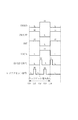
(タイミングチャート)
次に、この発明の実施の形態1による不揮発性半導体メモリの自動消去の動作を、図18のタイミングチャートと、図2に示したレジスタ回路群2と、図4に示したポンプ/メモリデコーダ用制御信号レジスタ6(1)および(2)の内容と、図8に示したポンプ/メモリデコーダ用制御信号レジスタ6の内容を用いて説明する。図18に示す各信号線は、図4に示したポンプ/メモリデコーダ用制御信号レジスタ6の各ビットに割り当てられた信号である。
【0115】
まず、図18の61のタイミングでこの発明の実施の形態1による不揮発性半導体メモリの自動消去の動作が開始する。
【0116】
次に、ロックビットチェックについて説明する。図18において、ロックビットチェックの期間は61〜67の間である。図18の62のタイミングでは、図18の63のタイミングでDBRD信号とLBCA信号をHレベルに、ISE信号をLレベルにするため、図18の62のタイミングで各信号線の値をレジスタのスレーブ側にセットする。レジスタへの値のセットは、図2に示したポンプ/メモリデコーダ用制御信号レジスタ6にDBバスを介して、データ処理装置1が値をセットする。図18の63のタイミングでは、図8に示した信号出力信号をイネーブルにすることによって、DBRD信号とLBCA信号をHレベルに、ISE信号をLレベルにする。
【0117】
次に、図18の64のタイミングでは、図18の65のタイミングでDBRD信号とLBCA信号をLレベルに、ISE信号をBLSHT信号をHレベルにするため、図18の64のタイミングで各信号線の値をレジスタのスレーブ側にセットする。レジスタへの値のセットは、図2に示したポンプ/メモリデコーダ用制御信号レジスタ2にDBバスを介して、データ処理装置1が値をセットする。図18の65のタイミングでは、図8に示した信号出力信号をイネーブルにすることによって、DBRD信号とLBCA信号をLレベルに、ISE信号をBLSHT信号をHレベルにする。
【0118】
次に、図18の66のタイミングでは、図18の67のタイミングでBLSHT信号をLレベルにするため、図18の66のタイミングで各信号線の値をレジスタのスレーブ側にセットする。レジスタへの値のセットは、図18に示したポンプ/メモリデコーダ用制御信号レジスタ6にDBバスを介して、データ処理装置1が値をセットする。図18の67のタイミングでは、図8に示した信号出力信号をイネーブルにすることによって、BLSHT信号をLレベルにする。
【0119】
次に、消去前書き込みについて説明する。
図18において、消去前書き込みの期間は、67〜73の間である。図18の68のタイミングでは、図18の69のタイミングでIPREP信号をLレベルにするため、図18の68のタイミングで各信号線の値をレジスタのスレーブ側にセットする。レジスタへの値のセットは、図18に示したポンプ/メモリデコーダ用制御信号レジスタ6にDBバスを介して、データ処理装置1が値をセットする。図18の69のタイミングでは、図8に示した信号出力信号をイネーブルにすることによって、IPREP信号をLレベルにする。
【0120】
次に、図18の70のタイミングでは、図18の71のタイミングでIPREP信号とBLSHT信号をHレベルにするため、図18の70のタイミングで各信号線の値をレジスタのスレーブ側にセットする。レジスタへの値のセットは、図2に示したポンプ/メモリデコーダ用制御信号レジスタ6にDBバスを介して、データ処理装置1が値をセットする。図18の71のタイミングでは、図8に示した信号出力信号をイネーブルにすることによって、IPREP信号とBLSHT信号をHレベルにする。
【0121】
次に、図18の72のタイミングでは、図18の73のタイミングでBLSHT信号をLレベルにするため、図18の72のタイミングで各信号線の値をレジスタのスレーブ側にセットする。レジスタへの値のセットは、図2に示したポンプ/メモリデコーダ用制御信号レジスタ6にDBバスを介して、データ処理装置1が値をセットする。図18の73のタイミングでは、図8に示した信号出力信号をイネーブルにすることによって、BLSHT信号をLレベルにする。
【0122】
次に、消去パルス印加と消去ベリファイについて説明する。図18において、消去パルス印加の期間は、73〜79の間である。また、消去ベリファイ期間は、79〜83の間である。図18の74のタイミングでは、図18の75のタイミングでNE信号とERS信号をHレベルにするため、図18の74のタイミングで各信号線の値をレジスタのスレーブ側にセットする。レジスタへの値のセットは、図2に示したポンプ/メモリデコーダ用制御信号レジスタ6にDBバスを介して、データ処理装置1が値をセットする。図18の75のタイミングでは、図8に示した信号出力信号をイネーブルにすることによって、NE信号とERS信号をHレベルにする。
【0123】
次に、図18の76のタイミングでは、図18の77のタイミングでNE信号とERS信号をLレベルに、BLSHT信号をHレベルにするため、図18の76のタイミングで各信号線の値をレジスタのスレーブ側にセットする。レジスタへの値のセットは、図2に示したポンプ/メモリデコーダ用制御信号レジスタ6にDBバスを介して、データ処理装置1が値をセットする。図18の77のタイミングでは、図8に示した信号出力信号をイネーブルにすることによって、NE信号とERS信号をLレベルに、BLSHT信号をHレベルにする。
【0124】
次に、図18の78のタイミングでは、図18の79のタイミングでBLSHT信号とISE信号をLレベルに、DBRD信号をHレベルにするため、図18の78のタイミングで各信号線の値をレジスタのスレーブ側にセットする。レジスタへの値のセットは、図2に示したポンプ/メモリデコーダ用制御信号レジスタ6にDBバスを介して、データ処理装置1が値をセットする。図18の79のタイミングでは、図8に示した信号出力信号をイネーブルにすることによって、BLSHT信号とISE信号をLレベルに、DBRD信号をHレベルにする。
【0125】
次に、図18の80のタイミングでは、図18の81のタイミングでDBRD信号をLレベルに、ISE信号をHレベルにするため、図18の80のタイミングで各信号線の値をレジスタのスレーブ側にセットする。レジスタへの値のセットは、図2に示したポンプ/メモリデコーダ用制御信号レジスタ6にDBバスを介して、データ処理装置1が値をセットする。図18の80のタイミングでは、図8に示した信号出力信号をイネーブルにすることによって、DBRD信号をLレベルに、ISE信号をHレベルにする。
【0126】
消去ベリファイの期間は、ベリファイでフェイルするか、消去の対象となっているメモリブロックの最大アドレスまで反復する。最大アドレスに達した場合、図18の83のタイミングでPE信号をLレベルにするため、図18の82のタイミングで各信号線の値をレジスタのスレーブ側にセットする。レジスタへの値のセットは、図2に示したポンプ/メモリデコーダ用制御信号レジスタ6にDBバスを介して、データ処理装置1が値をセットする。図18の82のタイミングでは、図8に示した信号出力信号をイネーブルにすることによってPE信号をLレベルにする。消去ベリファイでフェイルすれば、再度73のタイミングに戻り消去パルス印加を実行する。
【0127】
図18には、レジスタセット信号と信号出力信号を併せて示している。レジスタへの値のセットは、レジスタセット信号を用いて行う。また、各信号線の出力は信号出力信号を用いて行う。
【0128】
(自動書き込み)
次に、この発明の実施の形態1による不揮発性半導体メモリの自動書き込み動作を、図19のフローチャートを用いて説明する。
【0129】
モードエントリー後、まずロックビットチェックステップST84を行う。ロックビットチェックでは、書き込みの対象となるメモリブロックのロックビット情報を読み出し、書き込み可能か否かを判断する。強制書き込みモードである場合には、ロックビット情報によらず自動書き込みを実行する。
【0130】
また、非強制書き込みモードでロック状態にある時は、書き込みエラーステップST89として処理を終了する。書き込みパルス印加ステップST85のフェーズでは、取り込んだ書き込みアドレスとデータに従って、書き込みパルスを印加する。パルスの印加後、書き込みベリファイステップST86のフェーズに移行する。書き込みベリファイ86のフェーズでは、書き込みパルス印加後、書き込んだアドレスのデータを読み出し、外部より取り込んだデータと比較する。比較はワード単位で実行する。1ビットでも比較で不一致が生じれば、再度書き込みを行うために再書き込み前処理ステップST87のフェーズに処理を移す。比較で全データが一致すれば、正常処理ステップST88として処理を終了する。再書き込み前処理ステップST87のフェーズでは、書き込み回数をカウントするカウンターの値を+1インクリメントする。また、書き込みが失敗したビットを特定し、再び書き込みパルスを印加するために処理を書き込みパルス印加ステップST85に移す。書き込み回数のカウンター値が、最大値に到達すると、書き込みエラーステップST89として処理を終了する。
【0131】
(タイミングチャート)
次に、この発明の実施の形態1による不揮発性半導体メモリの自動書き込み動作を、図20のタイミングチャートと、図2に示したレジスタ回路群2と、図4に示したポンプ/メモリデコーダ用制御信号レジスタ6(1)および(2)の内容と、図8に示したポンプ/メモリデコーダ用制御信号レジスタ6の内容を用いて説明する。図20に示す各信号線は、図4に示したポンプ/メモリデコーダ用制御信号レジスタ6の各ビットに割り当てられた信号である。
【0132】
まず、図20の90のタイミングでこの発明の実施の形態1による不揮発性半導体メモリの自動書き込みの動作が開始する。
【0133】
次に、ロックビットチェックについて説明する。
図20において、ロックビットチェックの期間は90〜96の間である。図20の91のタイミングでは、図20の92のタイミングでDBRD信号とLBCA信号をHレベルに、ISE信号をLレベルにするため、図20の91のタイミングで各信号線の値をレジスタのスレーブ側にセットする。レジスタへの値のセットは、図2に示したポンプ/メモリデコーダ用制御信号レジスタ6にDBバスを介して、データ処理装置1が値をセットする。図20の92のタイミングでは、図8に示した信号出力信号をイネーブルにすることによって、DBRD信号とLBCA信号をHレベルに、ISE信号をLレベルにする。
【0134】
次に、図20の93のタイミングでは、図20の94のタイミングでDBRD信号とLBCA信号をLレベルに、ISE信号とBLSHT信号をHレベルにするため、図20の93のタイミングで各信号線の値をレジスタのスレーブ側にセットする。レジスタへの値のセットは、図2に示したポンプ/メモリデコーダ用制御信号レジスタ6にDBバスを介して、データ処理装置1が値をセットする。図20の94のタイミングでは、図8に示した信号出力信号をイネーブルにすることによって、DBRD信号とLBCA信号をLレベルに、ISE信号とBLSHT信号をHレベルにする。
【0135】
次に、図20の95のタイミングでは、図20の96のタイミングでBLSHT信号をLレベルに、PE信号をHレベルにするため、図20の95のタイミングで各信号線の値をレジスタのスレーブ側にセットする。レジスタへの値のセットは、図2に示したポンプ/メモリデコーダ用制御信号レジスタ6にDBバスを介して、データ処理装置1が値をセットする。図20の96のタイミングでは、図8に示した信号出力信号をイネーブルすることによって、BLSHT信号をLレベルに、PE信号をHにする。
【0136】
次に、書き込みパルス印加と書き込みベリファイについて説明する。
図20において、書き込みのパルス印加の期間は、96〜102の間である。また、書き込みベリファイの期間は、102〜106の間である。図20の97のタイミングでは、図20の98のタイミングでPGM信号をHレベルにするため、図20の97のタイミングで各信号線の値をレジスタのスレーブ側にセットする。レジスタへの値のセットは、図2に示したポンプ/メモリデコーダ用制御信号レジスタ6にDBバスを介してデータ処理装置1が値をセットする。図20の98のタイミングでは、図8に示した信号出力信号をイネーブルにすることによって、PGM信号をHレベルにする。
【0137】
次に、図20の99のタイミングでは、図20の100のタイミングでPGM信号をLレベルにするため、図20の99のタイミングで各信号線の値をレジスタのスレーブ側にセットする。レジスタへの値のセットは、図2に示したポンプ/メモリデコーダ用制御信号レジスタ6にDBバスを介して、データ処理装置1が値をセットする。図20の100のタイミングでは、図8に示した信号出力信号をイネーブルにすることによって、PGM信号をLレベルにする。
【0138】
次に、図20の101のタイミングでは、図20の102のタイミングでISE信号をLレベルに、DBRD信号をHレベルにするため、図20の101のタイミングで各信号線の値をレジスタのスレーブ側にセットする。レジスタへの値のセットは、図2に示したポンプ/メモリデコーダ用制御信号レジスタ6にDBバスを介して、データ処理装置1が値をセットする。図20の102のタイミングでは、図8に示した信号出力信号をイネーブルにすることによって、ISE信号をLレベルに、DBRD信号をHレベルにする。
【0139】
次に、図20の103のタイミングでは、図20の104のタイミングでDBRD信号をLレベルに、ISE信号をHレベルにするため、図20の103のタイミングで各信号線の値をレジスタのスレーブ側にセットする。レジスタへの値のセットは、図2に示したポンプ/メモリデコーダ用制御信号レジスタ6にDBバスを介して、データ処理装置1が値をセットする。図20の104のタイミングでは、図8に示した信号出力信号をイネーブルにすることによって、ISE信号をHレベルに、DBRD信号をLレベルにする。
【0140】
次に、図20の105のタイミングでは、図20の106のタイミングでPE信号をLレベルにするため、図20の105のタイミングで各信号線の値をレジスタのスレーブ側にセットする。レジスタへの値のセットは、図2に示したポンプ/メモリデコーダ用制御信号レジスタ6にDBバスを介して、データ処理装置1が値をセットする。図20の106のタイミングでは、図8に示した信号出力信号をイネーブルにすることによって、PE信号をLレベルにする。
【0141】
書き込みベリファイでフェイルすれば、再度96のタイミングに戻り、書き込みパルス印加を実行する。
【0142】
図20には、レジスタセット信号と信号出力信号を併せて示している。レジスタへの値のセットは、レジスタセット信号を用いて行う。また、各信号線の出力は、信号出力信号を用いて行う。
【0143】
次に、この発明の実施の形態1による不揮発性半導体メモリのロックビットプログラムの動作を、図21のフローチャートを用いて説明する。
モードエントリー後、まずロックビットチェックステップST107を行う。ロックビットチェックでは、書き込みの対象となるメモリブロックのロックビット情報を読み出し、書き込み可能か否かを判断する。強制書き込みモードである場合には、ロックビット情報によらず自動書き込みを実行する。
【0144】
非強制書き込みモードではロック状態にある時は、書き込みエラー終了ステップST112として処理を終了する。書き込みパルス印加ステップST108のフェーズでは、取り込んだ書き込みアドレスとデータに従って書き込みパルスを印加する。パルスの印加後書き込みベリファイステップST109のフェーズに移行する。書き込みベリファイステップST109のフェーズでは、書き込みパルス印加後、書き込んだロックビットデータを読み出し書き込みデータである“0”と比較する。不一致が生じれば、再度書き込みを行うために再書き込み前処理ステップST110のフェーズに処理を移す。
【0145】
比較でデータが一致すれば、正常終了ステップST111として処理を終了する。再書き込み前処理ステップST110のフェーズでは、書き込み回数をカウントするカウンターの値を+1インクリメントする。次に、再び書き込みパルスを印加するために、処理を書き込みパルス印加ステップST108に移す。書き込み回数のカウンター値が、最大値に到達すると、書き込みエラーステップST112として処理を終了する。
【0146】
(タイミングチャート)
次に、この発明の実施の形態1による不揮発性半導体メモリのロックビットプログラムの動作を、図22のタイミングチャートと、図2に示したレジスタ回路群2と、図4に示したポンプ/メモリデコーダ用制御信号レジスタ6(1)および(2)の内容と、図8に示したポンプ/メモリデコーダ用制御信号レジスタ6の内容を用いて説明する。図18に示す各信号線は、図4に示したポンプ/メモリデコーダ用制御信号レジスタ6の各ビットに割り当てられた信号である。
【0147】
まず、図22の113のタイミングでこの発明の実施の形態1による不揮発性半導体メモリのロックビットプログラムの動作が開始する。
【0148】
次に、ロックビットチェックについて説明する。図22において、ロックビットチェックの期間は113〜119の間である。図22の114のタイミングでは、図22の115のタイミングでDBRD信号とLBCA信号をHレベルに、ISE信号をLレベルにするため、図22の114のタイミングで各信号線の値をレジスタのスレーブ側にセットする。レジスタへの値のセットは、図2に示したポンプ/メモリデコーダ用制御信号レジスタ6にDBバスを介して、データ処理装置1が値をセットする。図22の115のタイミングでは、図8に示した信号出力信号をイネーブルにすることによってDBRD信号とLBCA信号をHレベルに、ISE信号をLレベルにする。
【0149】
次に、図22の116のタイミングでは、図22の117のタイミングでDBRD信号とLBCA信号をLレベルに、ISE信号とBLSHT信号をHレベルにするため、図22の116のタイミングで各信号線の値をレジスタのスレーブ側にセットする。レジスタへの値のセットは、図2に示したポンプ/メモリデコーダ用制御信号レジスタ6にDBバスを介して、データ処理装置1が値をセットする。図22の117のタイミングでは、図8に示した信号出力信号をイネーブルにすることによって、DBRD信号とLBCA信号をLレベルに、ISE信号とBLSHT信号をHレベルにする。
【0150】
次に、図22の118のタイミングでは、図22の119のタイミングでBLSHT信号をLレベルに、PE信号をHレベルにするため、図22の118のタイミングで各信号線の値をレジスタのスレーブ側にセットする。レジスタへの値のセットは、図2に示したポンプ/メモリデコーダ用制御信号レジスタ6にDBバスを介して、データ処理装置1が値をセットする。図22の119のタイミングでは、図8に示した信号出力信号をイネーブルにすることによって、BLSHT信号をLレベルに、PE信号をHレベルにする。
【0151】
次に、書き込みパルス印加と書き込みベリファイについて説明する。図22において、書き込みのパルス印加の期間は、119〜125の間である。また、書き込みベリファイの期間は、125〜129の間である。図22の120のタイミングでは、図22の121のタイミングでPGM信号とLBCA信号をHレベルにするため、図22の120のタイミングで各信号線の値をレジスタのスレーブ側にセットする。レジスタへの値のセットは、図2に示したポンプ/メモリデコーダ用制御信号レジスタ6にDBバスを介して、データ処理装置1が値をセットする。図22の121のタイミングでは、図8に示した信号出力信号をイネーブルにすることによって、PGM信号とLBCA信号をHレベルにする。
【0152】
次に、図22の122のタイミングでは、図22の123のタイミングでPGM信号をLレベルにするため、図22の122のタイミングで各信号線の値をレジスタのスレーブ側にセットする。レジスタへの値のセットは、図2に示したポンプ/メモリデコーダ用制御信号レジスタ6にDBバスを介して、データ処理装置1が値をセットする。図22の123のタイミングでは、図8に示した信号出力信号をイネーブルにすることによって、PGM信号をLレベルにする。
【0153】
次に、図22の124のタイミングでは、図22の125のタイミングでISE信号をLレベルに、DBRD信号をHレベルにするため、図22の124のタイミングで各信号線の値をレジスタのスレーブ側にセットする。レジスタへの値のセットは、図2に示したポンプ/メモリデコーダ用制御信号レジスタ6にDBバスを介して、データ処理装置1が値をセットする。図22の125のタイミングでは、図8に示した信号出力信号をイネーブルにすることによって、ISE信号をLレベルに、DBRD信号をHレベルにする。
【0154】
次に、図22の126のタイミングでは、図22の127のタイミングでDBRD信号とLBCA信号をLレベルに、ISE信号をHレベルにするため、図22の126のタイミングで各信号線の値をレジスタのスレーブ側にセットする。レジスタへの値のセットは、図2に示したポンプ/メモリデコーダ用制御信号レジスタ6にDBバスを介して、データ処理装置1が値をセットする。図22の127のタイミングでは、図8に示した信号出力信号をイネーブルにすることによって、ISE信号をHレベルに、DBRD信号とLBCA信号をLレベルにする。
【0155】
次に、図22の128のタイミングでは、図22の129のタイミングでPE信号をLレベルにするため、図22の128のタイミングで各信号線の値をレジスタのスレーブ側にセットする。レジスタへの値のセットは、図2に示したポンプ/メモリデコーダ用制御信号レジスタ6にDBバスを介して、データ処理装置1が値をセットする。図22の129のタイミングでは、図8に示した信号出力信号をイネーブルにすることによって、PE信号をLレベルにする。書き込みベリファイでフェイルすれば、再度119のタイミングに戻り書き込みパルス印加を実行する。
【0156】
図22には、レジスタセット信号と信号出力信号を併せて示している。レジスタへの値のセットは、レジスタセット信号を用いて行う。また、各信号線の出力は信号出力信号を用いて行う。
【0157】
(ロックビット読み出し)
(タイミングチャート)
次に、この発明の実施の形態1による不揮発性半導体メモリのロックビット読み出しの動作を、図23のタイミングチャートと、図2に示したレジスタ回路群2と、図4に示したポンプ/メモリデコーダ用制御信号レジスタ6(1)および(2)の内容と、図8に示したポンプ/メモリデコーダ用制御信号レジスタ6の内容を用いて説明する。図18に示す各信号線は、図4に示したポンプ/メモリデコーダ用制御信号レジスタ6の各ビットに割り当てられた信号である。
【0158】
まず、図23の130のタイミングでこの発明の実施の形態1による不揮発性半導体メモリのロックビットの読み出しの動作が開始する。
【0159】
図23において、ロックビット読み出しの期間は130〜134の間である。
図23の131のタイミングでは、図23の132のタイミングでDBRD信号とLBCA信号をHレベルに、ISE信号とBLSHT信号をLレベルにするため、図23の131のタイミングで各信号線の値をレジスタのスレーブ側にセットする。レジスタへの値のセットは、図2に示したポンプ/メモリデコーダ用制御信号レジスタ6にDBバスを介して、データ処理装置1が値をセットする。図23の132のタイミングでは、図8に示した信号出力信号をイネーブルにすることによって、DBRD信号とLBCA信号をHレベルに、ISE信号とBLSHT信号をLレベルにする。
【0160】
次に、図23の133のタイミングでは、図23の134のタイミングでDBRD信号とLBCA信号をLレベルに、ISE信号とBLSHT信号をHレベルにするため、図23の133のタイミングで各信号線の値をレジスタのスレーブ側にセットする。レジスタへの値のセットは、図2に示したポンプ/メモリデコーダ用制御信号レジスタ6にDBバスを介して、データ処理装置1が値をセットする。図23の134のタイミングでは、図8に示した信号出力信号をイネーブルにすることによって、DBRD信号とLBCA信号をLレベルに、ISE信号とBLSHT信号をHレベルにする。
【0161】
図23には、レジスタセット信号と信号出力信号を併せて示している。レジスタへの値のセットは、レジスタセット信号を用いて行う。また、各信号線の出力は信号出力信号を用いて行う。
【0162】
以上のように、この実施の形態1によれば、不揮発性半導体メモリ101と同一チップ内にあるデータ処理装置1を用いて、不揮発性半導体メモリの自動消去/自動書き込み/データ読み出しなどを実行することで、不揮発性半導体メモリ内に有する専用制御回路を削除し、その結果、チップ全体の回路規模が縮小できる効果が得られる。
【0163】
さらに、不揮発性半導体メモリ内に擬似的なレジスタを設け、レジスタ値を設定することによって、複数のメモリセルが行列状に配置されたメモリアレイで構成されたメモリブロック中のメモリアレイをダミーメモリアレイと置換することができる効果が得られる。
【0164】
【発明の効果】
以上のように、この発明によれば、不揮発性トランジスタからなる複数のメモリセルが行列状に配置されたメモリアレイで構成されたメモリブロックと、メモリアレイ内の不揮発性トランジスタのデータを、消去/書き込み/読み出しするために必要なメモリデコーダと、メモリアレイ内の不揮発性トランジスタのデータを、消去/書き込み/読み出しするために必要なチャージポンプと、メモリデコーダとチャージポンプを制御する複数本の制御信号のそれぞれをレジスタ1ビットに割り付けたレジスタと、レジスタの結合されたデータ処理装置によって上記レジスタの内容を更新する手段と、当該更新する手段がレジスタの内容を更新することによって、メモリデコーダおよびチャージポンプを制御する手段とを備えて不揮発性半導体メモリを構成したので、メモリデコーダとチャージポンプを制御する複数本の制御信号のそれぞれをレジスタ1ビットに割り付けたレジスタに結合されたデータ処理装置によってレジスタの内容を更新することにより、メモリデコーダとチャージポンプを制御することができ、したがって、専用の制御回路を必要とすることなく、小規模なハードウエア構成でメモリデコーダとチャージポンプを制御することを実現する効果がある。
【0165】
この発明によれば、メモリデコーダとチャージポンプを制御する複数本の制御信号のそれぞれをレジスタ1ビットに割り付けたレジスタに結合されたデータ処理装置により、レジスタの内容を更新することによって、メモリブロックを消去する手段をさらに備えるように構成したので、レジスタの内容を更新することによって、メモリデコーダとチャージポンプを制御することができ、専用の制御回路を必要とすることなく、小規模なハードウエア構成でメモリブロックを消去することを実現する効果がある。
【0166】
この発明によれば、メモリデコーダとチャージポンプを制御する複数本の制御信号のそれぞれをレジスタ1ビットに割り付けたレジスタに結合されたデータ処理装置により、レジスタの内容を更新することによって、メモリブロックにデータを書き込む手段をさらに備えるように構成したので、レジスタの内容を更新することによって、メモリデコーダとチャージポンプを制御することができ、専用の制御回路を必要とすることなく、小規模なハードウエア構成でメモリブロックにデータを書き込むことを実現する効果がある。
【0167】
この発明によれば、メモリデコーダとチャージポンプを制御する複数本の制御信号のそれぞれをレジスタ1ビットに割り付けたレジスタに結合されたデータ処理装置により、レジスタの内容を更新することによって、メモリブロックにデータを読み出す手段をさらに備えるように構成したので、レジスタの内容を更新することによって、メモリデコーダとチャージポンプを制御することができ、専用の制御回路を必要とすることなく、小規模なハードウエア構成でメモリブロックからデータを読み出すことを実現する効果がある。
【0168】
この発明によれば、不揮発性トランジスタからなる複数のメモリセルが行列状に配置されたメモリアレイで構成されたメモリブロックと、メモリアレイ内の不揮発性トランジスタのデータを、消去/書き込み/読み出しするために必要なメモリデコーダと、メモリアレイ内の不揮発性トランジスタのデータを、消去/書き込み/読み出しするために必要なチャージポンプと、メモリデコーダとチャージポンプを制御する複数本の制御信号のそれぞれをレジスタ1ビットに割り付けたレジスタと、レジスタの結合されたデータ処理装置によってレジスタの内容を更新する手段とを備えた不揮発性半導体メモリの消去方法は、当該更新する手段がレジスタの内容を更新することによって、メモリブロックのデータを消去するように構成したので、レジスタ内容の更新により、メモリデコーダとチャージポンプを制御することができ、したがって、専用の制御回路を必要とすることなく、小規模なハードウエア構成でメモリブロックのデータを消去することを実現する効果がある。
【0169】
この発明によれば、不揮発性トランジスタからなる複数のメモリセルが行列状に配置されたメモリアレイで構成されたメモリブロックと、メモリアレイ内の不揮発性トランジスタのデータを、消去/書き込み/読み出しするために必要なメモリデコーダと、メモリアレイ内の不揮発性トランジスタのデータを、消去/書き込み/読み出しするために必要なチャージポンプと、メモリデコーダとチャージポンプを制御する複数本の制御信号のそれぞれをレジスタ1ビットに割り付けたレジスタと、レジスタの結合されたデータ処理装置によってレジスタの内容を更新する手段とを備えた不揮発性半導体メモリの書き込み方法は、当該更新する手段がレジスタの内容を更新することによって、メモリブロックの不揮発性トランジスタにデータを書き込むように構成したので、レジスタ内容の更新により、メモリデコーダとチャージポンプを制御することができ、したがって、専用の制御回路を必要とすることなく、小規模なハードウエア構成でメモリブロックにデータを書き込むことを実現する効果がある。
【0170】
この発明によれば、不揮発性トランジスタからなる複数のメモリセルが行列状に配置されたメモリアレイで構成されたメモリブロックと、メモリアレイと置換することのできるダミーメモリアレイと、ダミーメモリアレイとメモリブロック内の1つのメモリアレイをトリミング処理によって置換することのできる第1の手段と、ダミーメモリアレイとメモリブロック内の1つのメモリアレイをダミーメモリアレイを含む置換回路によらず、疑似レジスタにデータをセットすることで置換することのできる第2の手段とを備えた不揮発性半導体メモリにおいて、第2の手段によって、第1の手段で行うメモリアレイとダミーメモリアレイの置換を行うように構成したので、この置換は予め行うことができるので、第1の手段で行うメモリアレイとダミーメモリアレイの置換前に、メモリアレイとダミーメモリアレイの置換が実施できる効果がある。
なお、置換回路によるダミーメモリアレイとメモリブロック内の1つのメモリアレイの置換が行われない時は、疑似レジスタにデータをセットすることでダミーメモリアレイとメモリブロック内の1つのメモリアレイを置換することができる。
【0171】
この発明によれば、第1の手段によって、ダミーメモリアレイとメモリブロック内の1つのメモリアレイの置換を行う場合には、第2の手段による置換処理が設定されている場合でも第1の手段による置換を優先させるように構成したので、第1の手段によるダミーメモリアレイとメモリブロック内の1つのメモリアレイの置換が実施できる効果がある。
なお、置換回路によるダミーメモリアレイとメモリブロック内の1つのメモリアレイの置換が行われている時は、疑似レジスタにデータがセットされていても置換回路によってダミーメモリアレイとメモリブロック内の1つのメモリアレイを置換することができる。
【0172】
この発明によれば、第1の手段によってダミーメモリアレイとメモリブロック内の1つのメモリアレイの置換を行う情報と、第2の手段による置換処理の情報とを読み出して比較し、第1の手段による置換処理が正しく行われたことを確認できる効果がある。
【0173】
この発明によれば、第2の手段による置換処理でセットされた疑似レジスタ値を不揮発性トランジスタからなるメモリセル内に書き込んだ後に読み出すように構成したので、不揮発性半導体メモリの電源電圧を立ち下げた後でも、第1の手段および第2の手段による置換処理の情報とを読み出してこれらを比較し、第1の手段による置換処理が正しく行われたことを確認できる効果がある。
【図面の簡単な説明】
【図1】 この発明の実施の形態1による不揮発性半導体メモリの機能ブロックとデータ処理装置を示すブロック図である。
【図2】 この発明の実施の形態1による不揮発性半導体メモリのレジスタ回路群を示すブロック図である。
【図3】 この発明の実施の形態1による不揮発性半導体メモリのレジスタ回路群の各種レジスタに割り付けられたアドレス空間を示す図である。
【図4】 ポンプ/メモリデコーダ用制御信号レジスタ(1)および(2)の内容を示す図である。
【図5】 ステータスレジスタの内容を示す図である。
【図6】 シーケンス制御レジスタの内容を示す図である。
【図7】 疑似LTレジスタの内容を示す図である。
【図8】 ポンプ/メモリデコーダ用制御信号レジスタのうち1ビット分の回路構成を示す図である。
【図9】 チャージポンプのブロック構成を示す図である。
【図10】 メモリデコーダの構成を示す図である。
【図11】 メモリブロックのアドレス空間を示す図である。
【図12】 128KBメモリブロックの構成を示す図である。
【図13】 ダミーメモリアレイを含む128KBメモリブロックの構成を示す図である。
【図14】 ダミーメモリアレイ、メモリアレイ、センスアンプ/書き込み回路、セレクタ、DDBバスの接続関係を示す図である。
【図15】 FUSE回路とデコード回路の接続関係を示す図である。
【図16】 FUSE回路トリミング仕様と疑似LTレジスタトリミング仕様を示す図である。
【図17】 自動消去のフローチャートを示す図である。
【図18】 自動消去のタイミングチャートを示す図である。
【図19】 自動書き込みのフローチャートを示す図である。
【図20】 自動書き込みのタイミングチャートを示す図である。
【図21】 ロックビット書き込みのフローチャートを示す図である。
【図22】 ロックビット書き込みのタイミングチャートを示す図である。
【図23】 ロックビット読み出しのタイミングチャートを示す図である。
【図24】 疑似LTレジスタとFUSE回路により置換されるパターンを示す図である。
【図25】 FUSE回路中のEnableFUSE信号とI/OFUSE信号生成回路を示す図である。
【図26】 従来の不揮発性半導体メモリを示すブロック図である。
【符号の説明】
1 データ処理装置、2 レジスタ回路群、3,1003 チャージポンプ、4 メモリデコーダ、5 メモリブロック、6 ポンプ/メモリデコーダ用制御信号レジスタ、7 アドレスレジスタ、8 データレジスタ、9 データバッファ、10 ステータスレジスタ、11 シーケンス制御レジスタ、12 コンペア回路、13 疑似LTレジスタ、16 AD(24:0)バス(更新する手段)、17 A(24:0)バス(更新する手段)、18 DDB(15:0)バス(更新する手段)、19 DB(15:0)バス(更新する手段)、20 負電圧チャージポンプ検出回路、21 正電圧チャージポンプ検出回路、22 読み出しチャージポンプ検出回路、23 電圧切り替え回路、24 X(ロウ)アドレスラッチ、25 Y(コラム)アドレス入力バッファラッチ、26 X(ロウ)アドレスプリデコーダ、26 Y(コラム)アドレスプリデコーダ、28〜32 メモリブロック(0)〜(4)、33 センスアンプ/書き込み回路(D0用)、34 Yデコーダ、35 Xデコーダ、44 センスアンプ/書き込み回路(ダミーメモリセルアレイ用)、45 ダミーメモリアレイ、46 メモリアレイ(0)、47 メモリアレイ(31)、48 センスアンプ/書き込み回路(D31用)、49 セレクタ(0)、50 セレクタ(31)、51 セレクタ、52 FUSE回路(第1の手段)、53 デコード回路(第2の手段)、101,1001 不揮発性半導体メモリ、135はセンスアンプ/書き込み回路、136 セレクタ回路、1002 メモリ/メモリデコーダ、1004 専用制御回路、b0〜b5,b7 疑似LTレジスタ(疑似レジスタ)。[0001]
BACKGROUND OF THE INVENTION
The present invention relates to a nonvolatile semiconductor memory using a nonvolatile transistor and an automatic erasing / automatic writing method thereof.
[0002]
[Prior art]
FIG. 26 is a block diagram showing the overall configuration of a conventional nonvolatile semiconductor memory, in which 1001 is a nonvolatile semiconductor memory, 1002 is a memory / memory decoder, 1003 is a charge pump, 1004 is a dedicated control circuit including an MCU and the like. It is.
[0003]
The memory /
[0004]
As described above, the conventional
[0005]
International Publication WO99 / 01824 discloses a method of controlling each control signal necessary for controlling an EEPROM in a semiconductor device incorporating an EEPROM by a register block including flip-flops instead of a dedicated control circuit. It is written. However, non-volatile semiconductor memories built in recent microcontrollers have many types of signals to be controlled, such as having a charge pump for generating a voltage necessary for erasing / writing inside the chip. Since there are a plurality of operation modes, a plurality of control signals are simultaneously activated by the register block composed of flip-flops shown in this WO99 / 01824, or different combinations of control signals for each operation mode. Cannot be controlled at the same timing.
[0006]
Further, the conventional nonvolatile semiconductor memory can replace a memory array in a memory block formed of a memory array in which a plurality of memory cells are arranged in a matrix with a dummy memory array. This replacement process is performed by cutting the FUSE circuit in the nonvolatile semiconductor memory with a laser.
[0007]
[Problems to be solved by the invention]
Since the conventional nonvolatile semiconductor memory and its automatic erasing / automatic writing method are configured as described above, the dedicated control circuit included in the memory is an LSI having the data processing device and the nonvolatile semiconductor memory in the same chip. There was a problem of mimicking the increase in circuit scale.
[0008]
Further, the FUSE circuit included in the conventional nonvolatile semiconductor memory has a problem that it cannot directly check whether or not the cutting is successful after being cut by the laser.
[0009]
Further, in a conventional nonvolatile semiconductor memory, a FUSE circuit is trimmed with a laser to replace a memory array in a memory block composed of a memory array in which a plurality of memory cells are arranged in a matrix with a dummy memory array. However, there was no method, and there was no method for pseudo replacement.
[0010]
The present invention has been made to solve the above-described problems, and performs automatic erasure / automatic writing / data reading of the nonvolatile semiconductor memory using a data processing device in the same chip as the nonvolatile semiconductor memory. An object of the present invention is to obtain a nonvolatile semiconductor memory and an automatic erasing / automatic writing method thereof that can delete the dedicated control circuit in the nonvolatile semiconductor memory and reduce the circuit scale of the entire chip.
[0011]
In addition, by providing a pseudo register in the nonvolatile semiconductor memory and setting a register value, a memory array in a memory block composed of memory cells in which a plurality of memory cells are arranged in a matrix is replaced with a dummy memory array. It is an object to obtain a nonvolatile semiconductor memory that can be replaced with
[0012]
[Means for Solving the Problems]
The nonvolatile semiconductor memory according to the present invention erases / writes data in a memory block composed of a memory array in which a plurality of memory cells made of nonvolatile transistors are arranged in a matrix and data in the nonvolatile transistors in the memory array A memory decoder necessary for reading / reading, a charge pump required for erasing / writing / reading data of nonvolatile transistors in the memory array, and a plurality of control signals for controlling the memory decoder and the charge pump. Each of the registers assigned to 1 bit of the register, means for updating the contents of the register by a data processing device coupled with the registers, and the means for updating controls the memory decoder and the charge pump by updating the contents of the register. And means for performing.
[0013]
The nonvolatile semiconductor memory according to the present invention further includes means for erasing the memory block by updating the contents of the register.
[0014]
The nonvolatile semiconductor memory according to the present invention further comprises means for writing data to the nonvolatile transistors in the memory block by updating the contents of the register.
[0015]
The nonvolatile semiconductor memory according to the present invention further includes means for reading data of nonvolatile transistors in the memory block by updating the contents of the register.
[0016]
According to an automatic erasing method of a nonvolatile semiconductor memory according to the present invention, a memory block composed of a memory array in which a plurality of memory cells composed of nonvolatile transistors are arranged in a matrix, and data of nonvolatile transistors in the memory array are stored. A memory decoder necessary for erasing / writing / reading, a charge pump necessary for erasing / writing / reading data of nonvolatile transistors in the memory array, and a plurality of memory decoders and charge pumps for controlling the charge pump In a non-volatile semiconductor memory comprising a register in which each of the control signals is assigned to a
[0017]
According to an automatic writing method of a nonvolatile semiconductor memory according to the present invention, a memory block composed of a memory array in which a plurality of memory cells composed of nonvolatile transistors are arranged in a matrix, and data of nonvolatile transistors in the memory array are stored. A memory decoder necessary for erasing / writing / reading, a charge pump necessary for erasing / writing / reading data of nonvolatile transistors in the memory array, and a plurality of memory decoders and charge pumps for controlling the charge pump In a non-volatile semiconductor memory comprising a register in which each of the control signals is assigned to a
[0018]
A nonvolatile semiconductor memory according to the present invention includes a memory block composed of a memory array in which a plurality of memory cells made of nonvolatile transistors are arranged in a matrix, a dummy memory array that can replace the memory array, a dummy First means capable of replacing the memory array and one memory array in the memory block by trimming processing, and replacing the dummy memory array and one memory array in the memory block without using a replacement circuit including the dummy memory array, A second means which can be replaced by setting data in the pseudo register; and a means for replacing the memory array performed by the first means and the dummy memory array by the second means. .
[0019]
In the nonvolatile semiconductor memory according to the present invention, when the replacement of the dummy memory array and one memory array in the memory block is performed by the first means, even when the replacement processing by the second means is set. The apparatus further includes means for giving priority to replacement by the first means.
[0020]
The non-volatile semiconductor memory according to the present invention reads and compares information for replacing the dummy memory array and one memory array in the memory block by the first means and information of the replacement processing by the second means. Means are further provided.
[0021]
The non-volatile semiconductor memory according to the present invention has means for reading out the pseudo register value set in the replacement process by the second means after writing it into the memory cell composed of the non-volatile transistor. The first means and the second means Means for reading out the information of the replacement processing by the means and comparing them.
[0022]
DETAILED DESCRIPTION OF THE INVENTION
An embodiment of the present invention will be described below.
(Block configuration)
FIG. 1 is a block diagram showing the entire configuration of a nonvolatile semiconductor memory according to
[0023]
The
[0024]
(Register circuit group)
FIG. 2 is a block diagram of a register circuit group of the nonvolatile semiconductor memory according to the first embodiment of the present invention. In FIG. 2, 6 is a control signal register for pump / memory decoder, 7 is an address register, and 8 is data. Register, 9 data buffer, 10 status register, 11 sequence control register, 12 compare circuit, 13 pseudo LT register, 14 memory decoder control signal, 15 charge pump control signal, 16 AD (24: 0) ) Bus (means for updating), 17 is A (24: 0) bus (means for updating), 18 is DDB (15: 0) bus (means for updating), 19 is DB (15: 0) bus (updating) Means) 137 is a register set signal, 138 is a block selection signal, and 139 is a signal output signal.
[0025]
The pump / memory decoder
[0026]
The
[0027]
The data register 8 holds write data at the time of automatic writing, and holds a lock bit value read at the time of reading the lock bit. There is an input / output path from the DB (15: 0)
[0028]
The
[0029]
The
[0030]
The sequence control register 11 is a 2-bit register. There are an erase verify start bit and an error setting bit for automatic erase. The input path from the DB (15: 0)
[0031]
The compare
[0032]
The pseudo LT register 13 is a register for setting data when a bit line is rewritten in a pseudo manner. There are as many registers as there are memory blocks. Data is set in the pseudo LT register 13 from the DB (15: 0)
[0033]
Next, FIG. 3 shows address spaces allocated to various registers in
[0034]
The
[0035]
The data register 8 includes a lower 8-bit data register (DATAL) and an upper 8-bit data register (DATAH). The data register (DATAL) and the data register (DATAH) are allocated to E4H and E5H.
[0036]
The
[0037]
The pump / memory decoder
[0038]
The output signal register is assigned to EEH. By setting 1 in the output signal register, the
[0039]
The sequence control register 11 is an 8-bit register and is assigned to F0H. The
[0040]
(Register specification)
(Pump / memory decoder control signal register 6)
FIG. 4 shows the contents of the pump / memory decoder
[0041]
B0 of the pump / memory decoder control signal register 6 (1) is assigned to the BYTE signal. When the nonvolatile semiconductor memory according to the first embodiment of the present invention is accessed in the byte mode, “1” is set to the BYTE signal. During word access, it is set to “0”. The BYTE signal is output to the
[0042]
B1 of the pump / memory decoder control signal register 6 (1) is assigned to the NE signal. The NE signal is set to “1” when the negative voltage pump mounted in the nonvolatile semiconductor memory according to the first embodiment of the present invention is activated. The NE signal is output to the
[0043]
B2 of the pump / memory decoder control signal register 6 (1) is assigned to the PE signal. The PE signal is set to “1” when the positive voltage pump mounted in the nonvolatile semiconductor memory according to the first embodiment of the present invention is activated. The PE signal is output to the
[0044]
B3 of the pump / memory decoder control signal register 6 (1) is assigned to the ERS signal. The ERS signal is set to “1” at the time of erasing as an erasing pulse. The ERS signal is output to the
[0045]
B4 of the pump / memory decoder control signal register 6 (1) is assigned to the PGM signal. The PGM signal is set to “1” at the time of writing as a write pulse. The PGM signal is output to the
[0046]
B5 of the pump / memory decoder control signal register 6 (1) is assigned to the DBRD signal. The DBRD signal is set to “1” when reading memory data. The DBRD signal is output to the
[0047]
B6 of the pump / memory decoder control signal register 6 (1) is assigned to the ISE signal. The ISE signal is set to “0” when data in the memory is read. The ISE signal is output to the
[0048]
B7 of the pump / memory decoder control signal register 6 (1) is assigned to the BLSHT signal. The BLSHT signal is set to “1” when the memory bit line is discharged. The BLSHT signal is output to the
[0049]
B8 of the pump / memory decoder control signal register 6 (2) is assigned to the IPREP signal. The IPREP signal is set to “0” at the time of programming before erasing as a programming pulse before erasing during automatic erasing. The IPREP signal is output to the
[0050]
B9 of the pump / memory decoder control signal register 6 (2) is assigned to the LBCA signal. The LBCA signal is set to “1” when the lock bit is accessed. The LBCA signal is output to the
[0051]
B10 of the pump / memory decoder control signal register 6 (2) is assigned to the RE signal. The RE signal activates the read charge pump. By default, b10 of the pump / memory decoder control signal register 6b is "1".
[0052]
(Status register 10)
Next, FIG. 5 shows the contents of the
[0053]
B4 of the
[0054]
B5 of the
[0055]
(Sequence control register 11)
Next, the contents of the sequence control register 11 are shown in FIG. Among the 8-bit registers, sequence flags are assigned to b0 and b1. The other bits are reserved bits. B0 of the sequence control register 11 is a verify start bit. “1” is set when verify is executed during automatic erasure.
[0056]
B1 of the sequence control register 11 is a verify status bit.
If an error occurs in the verify result during automatic erasure, “1” is set.
[0057]
(Pseudo LT register 13)
Next, FIG. 7 shows the contents of the
[0058]
As for the register values from b0 to b5, bit line replacement can be executed in a pseudo manner by setting “1” in the register corresponding to the bit line to be replaced. b7 is set to “1” when trimming data is set.
[0059]
(Hardware configuration)
(Circuit configuration of
Next, FIG. 8 shows a circuit configuration for one bit in the pump / memory decoder
[0060]
For setting the value in the register, the register set value is input from the data (bus value), and the value is held using the register set signal 137 as a trigger. The held data is output to the pump / memory decoder as a pump / memory decoder control signal using the
[0061]
(Charge pump)
Next, FIG. 9 shows a block diagram of the
[0062]
The
[0063]
The negative voltage charge pump is a charge pump for generating a negative voltage for erasing, and generates a negative voltage during automatic erasing.
[0064]
The positive voltage charge pump is a charge pump for generating a positive voltage for writing / erasing, and generates a positive write voltage at the time of writing and generates a positive erase voltage at the time of erasing.
[0065]
The read charge pump is a charge pump for generating a positive voltage for read / verify, and generates a read voltage during a read operation, and generates a verify voltage during write / write verify.
[0066]
Next, FIG. 10 shows a configuration diagram of the
In the figure, 24 is an X (row) address latch, 25 is a Y (column) address input buffer latch, 26 is an X (row) address predecoder, 27 is a Y (column) address predecoder, Memory block (0) to memory block (4), 135 is a sense amplifier / write circuit, 136 is a selector circuit, 138 is a block selection signal, and the other symbols that are the same as above indicate the same components or corresponding parts. Therefore, the duplicate description is omitted, and the same applies to the following.
[0067]
(Memory decoder)
First, the
[0068]
(Memory block)
The
[0069]
FIG. 11 shows the address space of the
The memory block (4) has an address space of “001000h” to “001FFFh” in hexadecimal notation.
The memory block (3) has an address space of “7D1000h” to “7EFFFFh” in hexadecimal notation.
The memory block (2) has an address space of “7F0000h” to “7FEFFFh” in hexadecimal notation.
The memory block (1) has an address space of “7FF000H” to “7FFFFH” in hexadecimal notation.
The memory block (0) has an address space of “FFE000H” to “FFFFFH” in hexadecimal notation.
[0070]
FIG. 12 is a diagram showing the extracted X decoder, Y decoder, memory cell array, and sense amplifier / write circuit of the 128 KB memory block (3) in the block shown in FIG. A writing circuit, 34 is a Y decoder, 35 is an X decoder, and 36 to 39 are transistors. It should be noted that the memory cell array shows only the amount coupled to one sense amplifier /
[0071]
The
[0072]
The
[0073]
Memory cells (Tr0-0 to Tr0-63, Tr1-0 to Tr1-63, Tr2-0 to Tr2-63, Tr3-0 to Tr3-63,..., Tr63-0 including a non-volatile transistor having a floating gate Tr63-63) are arranged in a matrix.
[0074]
Among these, memory cells (Tr0-0 to Tr63-0, Tr0-1 to Tr63-1, Tr0-2 to Tr63-2,..., Tr0-63 to Tr63-63) arranged in the same row are the same. Bit lines (BL0 to BL63) are connected to the source terminal, and different word lines (WL0 to WL63) are connected to the gate terminals.
[0075]
In reading memory data, one bit line and one word line are selected from the bit lines (BL0 to BL63) and the word lines (WL0 to WL63) according to the outputs of the
[0076]
In addition, according to the outputs of the
[0077]
Further, when erasing the memory data, an erasing pulse (ERS) is applied to the memory block to be erased, and a positive erasing voltage is applied to the gate of the memory cell composed of a nonvolatile transistor having a floating gate. The contents of the memory are erased.
[0078]
(Dummy memory array)
FIG. 13 is a diagram showing an extracted X decoder, Y decoder, dummy memory cell array, lock bit cell array, sense amplifier / write circuit, and selector circuit in the 128 KB memory block (3) in the block shown in FIG. In the figure,
[0079]
The
[0080]
The
[0081]
The lock bit line (LBL) is a bit line connected to a nonvolatile transistor (Tr00-0) indicating a locked / unlocked state for each memory block.
[0082]
Further, dummy memory cells and lock bit memory cells (Tr00-0 to Tr00-64, Tr10-0 to Tr1-64, Tr20-0 to Tr20-64, Tr30-0 to Tr30-) composed of nonvolatile transistors having floating gates. 64,..., Tr630-0 to Tr630-64) are arranged in a matrix.
[0083]
Among these, memory cells (Tr00-0 to Tr630-0, Tr00-1 to Tr630-1, Tr00-2 to Tr630-2,..., Tr00-64 to Tr630-64) arranged in the same row are the same. Bit lines (DBL1 to DBL64) are connected to the source terminal, and different word lines (WL0 to WL63) are connected to the gate terminal. DBL1 to DBL64 are dummy bit lines, and LBL is a lock bit line.
[0084]
Reading of dummy memory cell data is performed by selecting one bit line and one word line from the bit lines (DBL1 to DBL64) and the word lines (WL0 to WL63) according to the outputs of the
[0085]
In addition, writing to the dummy memory cell data is performed according to the outputs of the
[0086]
Further, when erasing the memory data, an erasing pulse (ERS) is applied to the memory block to be erased, and a positive erasing voltage is applied to the gate of the memory cell composed of a nonvolatile transistor having a floating gate. The contents of the memory are erased.
[0087]
14 shows a dummy memory cell array, memory array (0) to memory array (31), sense amplifier / write circuit, sense amplifier / write circuit (for D0) to sense amplifier / write circuit (for D31), selector (0). ~ Is a diagram showing the connection relationship between the selector (31) and the DDB bus (15: 0), in which 135 is a sense amplifier / write circuit, 33 is a sense amplifier / write circuit (for D0), 48 is Sense amplifier / write circuit (for D31), 44 is a sense amplifier / write circuit (for dummy memory cell array), 45 is a dummy memory array, 46 is a memory array (0), 47 is a memory array (31), 49 is a selector ( 0), 136 is a selector circuit, 50 is a selector (31), and 51 is a selector (31).
[0088]
The
[0089]
The selectors (0) 49 to (31) 50 are selected by the control signals IREDEBL (0) to IREDEBL (31), and the memory arrays to be replaced (
[0090]
Further, the sense amplifier /
[0091]
FIG. 15 is a block diagram for generating the control signal IREDEBL (31: 0). In the figure, 52 is a FUSE circuit (first means), 53 is a decode circuit (second means), b0 to b5 and b7 are pseudo LT registers (pseudo registers), and the control signal IREDEBL (31: 0) is The
[0092]
FIG. 25 shows the EnableFUSE signal generation circuit (a) and the I / OFUSE signal generation circuit (b) in the
[0093]
The EnableFUSE signal generation circuit of FIG. 25A includes a P-
[0094]
On the other hand, the I / OFUSE signal generation circuit of FIG. 25B includes a P-
[0095]
The FUSE 144 in the EnableFUSE signal generation circuit and the
[0096]
Further, when the EnableFUSE signal is at the H level, the I / OFUSE signal is at the L level after the reset signal is input unless the
[0097]
FIG. 16 shows the FUSE circuit trimming specification (a) and the pseudo LT register trimming specification (b). In FUSE circuit trimming, when EnableFUSE = H level and I / OFUSE (4: 0) = L level, the IOEDEBL (0) signal becomes active, and the memory cell array (0) 46 shown in FIG. Replaced.
[0098]
Further, in the pseudo LT register trimming specification, when the pseudo LT register output b5 = H level and the pseudo LT register outputs b4 to b0 = L level, the IOEDEBL (0) signal becomes active, and the memory cell array (0) shown in FIG. 46 is replaced with a dummy
[0099]
Further, FIG. 24 shows some examples of patterns to be replaced. First, the case of (1) replaced by the FUSE circuit output is shown. In pattern {circle around (1)}, the output of the FUSE circuit shows the output for replacing the memory cell arrays (0) to (7) with the dummy memory cell array, respectively, but the output of the pseudo LT register indicates that the
[0100]
Furthermore, pattern (2) replaced by the pseudo LT register output is shown. In pattern (2), the output of the FUSE circuit does not indicate any memory cell replacement, but the output of the pseudo LT register indicates the output for replacing the memory cell arrays (8) to (15) with dummy memory cell arrays, respectively. Yes. In this case, since the
[0101]
Furthermore, the case of pattern (3) replaced by the FUSE circuit output is shown. In pattern {circle around (3)}, the output of the FUSE circuit indicates an output for replacing the
[0102]
Finally, the case of pattern {circle around (4)} that is not replaced anywhere is shown. In pattern (4), neither the FUSE circuit nor the output of the pseudo LT register nor the replacement of any memory cell is shown. In this case, the
[0103]
The pseudo LT register value can be read out to the
[0104]
(Description of operation)
(Auto Erase)
Next, the automatic erasing operation of the nonvolatile semiconductor memory according to the first embodiment of the present invention will be described with reference to the flowchart of FIG. In the automatic batch erasure in this case, any one of the block (0) 28, block (1) 29, block (2) 30, block (3) 31, block (4) 32 shown in FIG. Target.
[0105]
After the mode entry, first, a lock bit check step ST54 is performed. In the lock bit check step ST54, it is determined whether or not the lock bit information of the memory block to be erased can be read and erased. As a result of reading the lock bit information, if the lock bit information is in the locked state, the process ends as an erase error step ST60. On the other hand, if it is in the unlocked state, the process proceeds to the phase of the next pre-erase write step ST55. Here, even in the locked state, when the forced erase mode is set, the process proceeds to the phase of the next pre-erase write step ST55.
[0106]
In the phase of the pre-erase write step ST55, an operation of writing data “0” to the memory block to be erased is performed.
[0107]
In the phase of the pre-erase write step ST55, writing is performed in units of 32 bits while sequentially incrementing the address. After the completion of the phase of the pre-erase write step ST55, the process proceeds to the phase of the erase pulse application step ST56.
[0108]
In the phase of the erase pulse application step ST56, the erase pulse is applied only to the memory block to be erased to perform the erase operation. After the completion of the erase pulse application step ST56, the process proceeds to the erase verify step ST57.
[0109]
In the phase of erase verify step ST57, erase verify processing is performed on the memory block to be erased while incrementing the address from the lowest address to the highest address. If a verify failure (defective) occurs in the phase of the erase verify step ST57, the process proceeds to the phase of the pre-reerase processing step ST58 in order to perform re-erase.
[0110]
In the phase of pre-erase processing step ST58, the number of times of pre-erase processing is incremented by 1, and the process is shifted again to the erase pulse application step ST56 phase.
[0111]
In the erase pulse application step ST56, the erase operation is performed again. After the phase of the erase pulse application step ST56 is completed, the process proceeds to the phase of the erase verify step ST57 again. In the phase of the erase verify step ST57, the verify is started again from the address at which the previous erase verify failed.
[0112]
In the phase of the erase pulse application step ST56, the phase of the erase verify step ST57, and the phase of the pre-erase process step ST58, verify is performed up to the final address in the phase of the erase verify step ST57, or the process of the pre-erase process step ST58. The loop processing is continued until the value of the number of pre-erasure processing times reaches the maximum value in the phase.
[0113]
When the value of the number of times of pre-erase processing reaches the maximum value in the phase of pre-reerase process step ST58, the process ends as an erase error end step ST60. Further, when the verification proceeds to the final address in the phase of the erase verify step ST57, the automatic erase process is terminated as a normal end step ST59.
[0114]
(Timing chart)
Next, the automatic erasure operation of the nonvolatile semiconductor memory according to the first embodiment of the present invention is performed for the timing chart of FIG. 18, the
[0115]
First, the automatic erasure operation of the nonvolatile semiconductor memory according to the first embodiment of the present invention starts at the
[0116]
Next, the lock bit check will be described. In FIG. 18, the lock bit check period is between 61 and 67. At the
[0117]
Next, at the timing of 64 in FIG. 18, the DBRD signal and the LBCA signal are set to the L level at the timing of 65 in FIG. 18, and the BLSHT signal is set to the H level at the timing of 65 in FIG. Is set to the slave side of the register. The value is set in the register by the
[0118]
Next, at the
[0119]
Next, writing before erasure will be described.
In FIG. 18, the pre-erase write period is between 67-73. At the timing of 68 in FIG. 18, the IPREP signal is set to the L level at the timing of 69 in FIG. 18, so that the value of each signal line is set to the slave side of the register at the timing of 68 in FIG. The value is set in the register by the
[0120]
Next, at the
[0121]
Next, at the
[0122]
Next, erase pulse application and erase verify will be described. In FIG. 18, the erase pulse application period is between 73-79. The erase verify period is between 79 and 83. At the timing of 74 in FIG. 18, the NE signal and the ERS signal are set to the H level at the timing of 75 in FIG. 18. Therefore, the value of each signal line is set to the slave side of the register at the timing of 74 in FIG. The value is set in the register by the
[0123]
Next, at the timing of 76 in FIG. 18, the NE signal and the ERS signal are set to the L level and the BLSHT signal is set to the H level at the timing of 77 in FIG. Set to the slave side of the register. The value is set in the register by the
[0124]
Next, at timing 78 in FIG. 18, the BLSHT signal and ISE signal are set to L level and the DBRD signal is set to H level at
[0125]
Next, at the
[0126]
During the erase verify period, the verification is failed or repeated until the maximum address of the memory block to be erased. When the maximum address is reached, the PE signal is set to the L level at the
[0127]
FIG. 18 shows a register set signal and a signal output signal together. A value is set in the register using a register set signal. Each signal line is output using a signal output signal.
[0128]
(Automatic writing)
Next, the automatic write operation of the nonvolatile semiconductor memory according to the first embodiment of the present invention will be described with reference to the flowchart of FIG.
[0129]
After the mode entry, first, a lock bit check step ST84 is performed. In the lock bit check, the lock bit information of the memory block to be written is read to determine whether or not writing is possible. In the forced write mode, automatic writing is executed regardless of the lock bit information.
[0130]
When the lock state is set in the non-forced write mode, the process ends as a write error step ST89. In the phase of write pulse application step ST85, a write pulse is applied according to the fetched write address and data. After the application of the pulse, the process proceeds to the phase of the write verify step ST86. In the phase of the write verify 86, after applying the write pulse, the data at the written address is read and compared with the data taken in from the outside. The comparison is performed in word units. If even one bit does not match in the comparison, the process proceeds to the phase of pre-rewrite processing step ST87 in order to perform writing again. If all the data match in the comparison, the process ends as normal process step ST88. In the phase of pre-rewrite processing step ST87, the value of the counter for counting the number of times of writing is incremented by +1. Further, the bit in which the writing has failed is specified, and the process proceeds to the writing pulse applying step ST85 in order to apply the writing pulse again. When the counter value of the number of times of writing reaches the maximum value, the process ends as a write error step ST89.
[0131]
(Timing chart)
Next, the automatic write operation of the nonvolatile semiconductor memory according to the first embodiment of the present invention will be described with reference to the timing chart of FIG. 20, the
[0132]
First, the automatic writing operation of the nonvolatile semiconductor memory according to the first embodiment of the present invention starts at the
[0133]
Next, the lock bit check will be described.
In FIG. 20, the period of the lock bit check is between 90 and 96. At the
[0134]
Next, at timing 93 in FIG. 20, the DBRD signal and the LBCA signal are set to L level and the ISE signal and BLSHT signal are set to H level at
[0135]
Next, at the
[0136]
Next, write pulse application and write verify will be described.
In FIG. 20, the period of pulse application for writing is between 96 and 102. The write verify period is between 102 and 106. At the
[0137]
Next, at the
[0138]
Next, at the
[0139]
Next, at the timing of 103 in FIG. 20, the DBRD signal is set to the L level and the ISE signal is set to the H level at the timing of 104 in FIG. Set to the side. The value is set in the register by the
[0140]
Next, at the timing of 105 in FIG. 20, the PE signal is set to the L level at the timing of 106 in FIG. 20, so the value of each signal line is set to the slave side of the register at the timing of 105 in FIG. The value is set in the register by the
[0141]
If the write verify fails, the timing returns to 96 again and the write pulse application is executed.
[0142]
FIG. 20 shows both the register set signal and the signal output signal. A value is set in the register using a register set signal. Each signal line is output using a signal output signal.
[0143]
Next, the operation of the lock bit program of the nonvolatile semiconductor memory according to
After the mode entry, first, a lock bit check step ST107 is performed. In the lock bit check, the lock bit information of the memory block to be written is read to determine whether or not writing is possible. In the forced write mode, automatic writing is executed regardless of the lock bit information.
[0144]
When in the non-forced write mode, the process is ended as a write error end step ST112 when in the locked state. In the phase of the write pulse application step ST108, a write pulse is applied according to the fetched write address and data. After applying the pulse, the process proceeds to the phase of the write verify step ST109. In the phase of the write verify step ST109, after the write pulse is applied, the written lock bit data is compared with “0” which is the read write data. If a mismatch occurs, the process proceeds to the phase of pre-rewrite processing step ST110 in order to perform writing again.
[0145]
If the data match in the comparison, the process ends as normal end step ST111. In the phase of pre-rewrite processing step ST110, the value of the counter for counting the number of times of writing is incremented by +1. Next, in order to apply the write pulse again, the processing shifts to the write pulse application step ST108. When the counter value of the number of times of writing reaches the maximum value, the processing ends as a writing error step ST112.
[0146]
(Timing chart)
Next, the operation of the lock bit program of the nonvolatile semiconductor memory according to the first embodiment of the present invention will be described with reference to the timing chart of FIG. 22, the
[0147]
First, at the timing of 113 in FIG. 22, the operation of the lock bit program of the nonvolatile semiconductor memory according to the first embodiment of the present invention is started.
[0148]
Next, the lock bit check will be described. In FIG. 22, the period of the lock bit check is between 113 and 119. At the timing of 114 in FIG. 22, the DBRD signal and the LBCA signal are set to the H level and the ISE signal is set to the L level at the timing of 115 in FIG. Set to the side. The value is set in the register by the
[0149]
Next, at the
[0150]
Next, at the
[0151]
Next, write pulse application and write verify will be described. In FIG. 22, the period of application of the pulse for writing is between 119 and 125. The write verify period is between 125 and 129. At the
[0152]
Next, at the
[0153]
Next, at the timing of 124 in FIG. 22, the ISE signal is set to the L level and the DBRD signal is set to the H level at the timing of 125 in FIG. Set to the side. The value is set in the register by the
[0154]
Next, at the timing of 126 in FIG. 22, the DBRD signal and the LBCA signal are set to the L level and the ISE signal is set to the H level at the timing of 127 in FIG. Set to the slave side of the register. The value is set in the register by the
[0155]
Next, at the timing of 128 in FIG. 22, the value of each signal line is set to the slave side of the register at the timing of 128 in FIG. 22 in order to set the PE signal to the L level at the timing of 129 in FIG. The value is set in the register by the
[0156]
FIG. 22 shows both the register set signal and the signal output signal. A value is set in the register using a register set signal. Each signal line is output using a signal output signal.
[0157]
(Read lock bit)
(Timing chart)
Next, the operation of reading the lock bit of the nonvolatile semiconductor memory according to the first embodiment of the present invention will be described with reference to the timing chart of FIG. 23, the
[0158]
First, the read operation of the lock bit of the nonvolatile semiconductor memory according to the first embodiment of the present invention starts at the timing of 130 in FIG.
[0159]
In FIG. 23, the lock bit read period is between 130 and 134.
At the timing of 131 in FIG. 23, the DBRD signal and the LBCA signal are set to the H level and the ISE signal and the BLSHT signal are set to the L level at the timing of 132 in FIG. Set to the slave side of the register. The value is set in the register by the
[0160]
Next, at the
[0161]
FIG. 23 shows both the register set signal and the signal output signal. A value is set in the register using a register set signal. Each signal line is output using a signal output signal.
[0162]
As described above, according to the first embodiment, automatic erasure / automatic writing / data reading of the nonvolatile semiconductor memory is executed using the
[0163]
Furthermore, by providing a pseudo register in the nonvolatile semiconductor memory and setting a register value, a memory array in a memory block configured by a memory array in which a plurality of memory cells are arranged in a matrix is replaced with a dummy memory array. The effect which can be substituted is obtained.
[0164]
【The invention's effect】
As described above, according to the present invention, the memory block composed of a memory array in which a plurality of memory cells made of nonvolatile transistors are arranged in a matrix and the data of the nonvolatile transistors in the memory array can be erased / A memory decoder necessary for writing / reading, a charge pump necessary for erasing / writing / reading data of the nonvolatile transistors in the memory array, and a plurality of control signals for controlling the memory decoder and the charge pump Each of which is assigned to one bit of the register, means for updating the contents of the register by a data processing device to which the registers are coupled, and the updating means updates the contents of the register so that the memory decoder and the charge pump Means for controlling the non-volatile semiconductor memory The memory decoder and the charge are updated by updating the contents of the register by a data processor coupled to the register in which each of the control signals for controlling the memory decoder and the charge pump is assigned to the
[0165]
According to the present invention, the memory block is updated by updating the contents of the register by the data processing device coupled to the register in which each of the control signals for controlling the memory decoder and the charge pump is assigned to the
[0166]
According to the present invention, the memory block is updated by updating the contents of the register by the data processor coupled to the register in which each of the control signals for controlling the memory decoder and the charge pump is assigned to the
[0167]
According to the present invention, the memory block is updated by updating the contents of the register by the data processor coupled to the register in which each of the control signals for controlling the memory decoder and the charge pump is assigned to the
[0168]
According to the present invention, for erasing / writing / reading data of a memory block composed of a memory array in which a plurality of memory cells made of nonvolatile transistors are arranged in a matrix and data of the nonvolatile transistors in the memory array. Each of the memory decoder necessary for the memory, the charge pump necessary for erasing / writing / reading the data of the nonvolatile transistors in the memory array, and a plurality of control signals for controlling the memory decoder and the charge pump are respectively registered in the register 1 A nonvolatile semiconductor memory erasing method comprising a register assigned to a bit and a means for updating the contents of the register by a data processing device coupled with the register, wherein the updating means updates the contents of the register. Since it was configured to erase the data in the memory block, By updating the register contents, it is possible to control the memory decoder and the charge pump. Therefore, it is possible to erase the data in the memory block with a small hardware configuration without requiring a dedicated control circuit. There is.
[0169]
According to the present invention, for erasing / writing / reading data of a memory block composed of a memory array in which a plurality of memory cells made of nonvolatile transistors are arranged in a matrix and data of the nonvolatile transistors in the memory array. Each of the memory decoder necessary for the memory, the charge pump necessary for erasing / writing / reading the data of the nonvolatile transistors in the memory array, and a plurality of control signals for controlling the memory decoder and the charge pump are respectively registered in the register 1 A nonvolatile semiconductor memory writing method comprising a register assigned to a bit and a means for updating the contents of the register by a data processor coupled to the register, the updating means updates the contents of the register, Write data to the nonvolatile transistors in the memory block Therefore, it is possible to control the memory decoder and charge pump by updating the register contents. Therefore, data can be stored in the memory block with a small hardware configuration without requiring a dedicated control circuit. This has the effect of realizing writing.
[0170]
According to the present invention, a memory block composed of a memory array in which a plurality of memory cells made of nonvolatile transistors are arranged in a matrix, a dummy memory array that can replace the memory array, a dummy memory array, and a memory The first means that can replace one memory array in the block by trimming processing, and the dummy memory array and the one memory array in the memory block are transferred to the pseudo register without using the replacement circuit including the dummy memory array. In the nonvolatile semiconductor memory provided with the second means that can be replaced by setting the memory array, the second means replaces the memory array performed by the first means and the dummy memory array. Since this replacement can be performed in advance, the memory array performed by the first means Before replacement of the dummy memory array, replacement of the memory array and dummy memory array has the effect that can be implemented.
When the replacement circuit does not replace the dummy memory array and one memory array in the memory block, the dummy memory array and one memory array in the memory block are replaced by setting data in the pseudo register. be able to.
[0171]
According to the present invention, when the replacement of the dummy memory array and one memory array in the memory block is performed by the first means, the first means even when the replacement processing by the second means is set. Therefore, there is an effect that replacement of the dummy memory array and one memory array in the memory block by the first means can be performed.
When replacement of the dummy memory array and one memory array in the memory block by the replacement circuit is performed, even if data is set in the pseudo register, one of the dummy memory array and the memory block is replaced by the replacement circuit. The memory array can be replaced.
[0172]
According to the present invention, the information for replacing the dummy memory array and one memory array in the memory block by the first means and the information of the replacement processing by the second means are read and compared, and the first means This has the effect of confirming that the replacement process by has been performed correctly.
[0173]
According to the present invention, since the pseudo register value set in the replacement process by the second means is read out after being written into the memory cell composed of the nonvolatile transistor, the power supply voltage of the nonvolatile semiconductor memory is lowered. Even after this, there is an effect that the information of the replacement process by the first means and the second means can be read out and compared to confirm that the replacement process by the first means has been performed correctly.
[Brief description of the drawings]
FIG. 1 is a block diagram showing a functional block and a data processing device of a nonvolatile semiconductor memory according to a first embodiment of the present invention.
FIG. 2 is a block diagram showing a register circuit group of a nonvolatile semiconductor memory according to a first embodiment of the present invention.
FIG. 3 is a diagram showing an address space assigned to various registers in a register circuit group of the nonvolatile semiconductor memory according to the first embodiment of the present invention;
FIG. 4 is a diagram showing the contents of pump / memory decoder control signal registers (1) and (2).
FIG. 5 is a diagram showing the contents of a status register.
FIG. 6 is a diagram showing the contents of a sequence control register.
FIG. 7 is a diagram showing the contents of a pseudo LT register.
FIG. 8 is a diagram showing a circuit configuration for one bit in a pump / memory decoder control signal register.
FIG. 9 is a diagram showing a block configuration of a charge pump.
FIG. 10 is a diagram illustrating a configuration of a memory decoder.
FIG. 11 is a diagram showing an address space of a memory block.
FIG. 12 is a diagram showing a configuration of a 128 KB memory block.
FIG. 13 is a diagram showing a configuration of a 128 KB memory block including a dummy memory array.
FIG. 14 is a diagram showing a connection relationship among a dummy memory array, a memory array, a sense amplifier / write circuit, a selector, and a DDB bus.
FIG. 15 is a diagram illustrating a connection relationship between a FUSE circuit and a decode circuit.
FIG. 16 is a diagram showing a FUSE circuit trimming specification and a pseudo LT register trimming specification.
FIG. 17 is a diagram showing a flowchart of automatic erasure.
FIG. 18 is a diagram showing a timing chart of automatic erasure.
FIG. 19 is a diagram showing a flowchart of automatic writing.
FIG. 20 is a diagram showing a timing chart of automatic writing.
FIG. 21 is a diagram showing a flowchart of lock bit writing.
FIG. 22 is a diagram showing a timing chart of writing a lock bit.
FIG. 23 is a timing chart of lock bit reading.
FIG. 24 is a diagram showing a pattern replaced by a pseudo LT register and a FUSE circuit.
FIG. 25 is a diagram showing an EnableFUSE signal and an I / OFUSE signal generation circuit in the FUSE circuit.
FIG. 26 is a block diagram showing a conventional nonvolatile semiconductor memory.
[Explanation of symbols]
1 data processing device, 2 register circuit group, 3,1003 charge pump, 4 memory decoder, 5 memory block, 6 control signal register for pump / memory decoder, 7 address register, 8 data register, 9 data buffer, 10 status register, 11 Sequence control register, 12 Compare circuit, 13 Pseudo LT register, 16 AD (24: 0) bus (means for updating), 17 A (24: 0) bus (means for updating), 18 DDB (15: 0) bus (Means for updating), 19 DB (15: 0) bus (means for updating), 20 negative voltage charge pump detection circuit, 21 positive voltage charge pump detection circuit, 22 read charge pump detection circuit, 23 voltage switching circuit, 24 X (Row) address latch, 25 Y (column) address input buffer Latch, 26 X (row) address predecoder, 26 Y (column) address predecoder, 28 to 32 memory blocks (0) to (4), 33 sense amplifier / write circuit (for D0), 34 Y decoder, 35 X Decoder, 44 sense amplifier / write circuit (for dummy memory cell array), 45 dummy memory array, 46 memory array (0), 47 memory array (31), 48 sense amplifier / write circuit (for D31), 49 selector (0) , 50 selector (31), 51 selector, 52 FUSE circuit (first means), 53 decode circuit (second means), 101, 1001 nonvolatile semiconductor memory, 135 is a sense amplifier / write circuit, 136 selector circuit, 1002 Memory / memory decoder, 1004 dedicated control circuit, b0 to b5 b7 pseudo LT register (pseudo-registers).
Claims (1)
上記メモリアレイと置換することのできるダミーメモリアレイと、
上記ダミーメモリアレイと上記メモリブロック内の1つのメモリアレイを複数のヒューズ素子の選択的なトリミング処理によって生成される多ビットのヒューズ信号に基づいて置換することのできる第1の手段と、
上記ダミーメモリアレイと上記メモリブロック内の1つのメモリアレイを上記ダミーメモリアレイを含む置換回路によらず、疑似レジスタに上記ヒューズ信号に対応する多ビットのデータをセットすることで置換することのできる第2の手段と、
上記第1の手段で行う上記メモリアレイと上記ダミーメモリアレイの置換の実施前に当該第2の手段によって、上記第1の手段で行う上記メモリアレイと上記ダミーメモリアレイの置換を行い、上記第1の手段による置換の実施後には、上記第2の手段による置換処理が設定されている場合でも上記第1の手段による置換を優先させる手段と、
上記第2の手段による置換処理が設定されているときに上記第1の手段による置換処理を行った場合に上記第1の手段による置換処理が正しく行われたことを確認するために、上記第1の手段によってダミーメモリアレイとメモリブロック内の1つのメモリアレイの置換を行う情報である上記ヒューズ信号と、上記第2の手段による置換処理の情報である上記疑似レジスタにセットされたデータとを、上記複数のヒューズ素子を含む置換回路および上記疑似レジスタに接続されたデータ線を介して読み出して比較する手段とを備えた不揮発性半導体メモリ。A memory block including a memory array in which a plurality of memory cells including nonvolatile transistors are arranged in a matrix; and
A dummy memory array that can replace the memory array;
First means capable of replacing the dummy memory array and one memory array in the memory block based on a multi-bit fuse signal generated by selective trimming processing of a plurality of fuse elements ;
The dummy memory array and one memory array in the memory block can be replaced by setting multi-bit data corresponding to the fuse signal in the pseudo register without using a replacement circuit including the dummy memory array. A second means;
Said the first of the memory array and the second prior to performing replacement of the dummy memory array performed by means of means, have row replacement of the memory array and the dummy memory array performing in the first unit, the Means for giving priority to the replacement by the first means even when the replacement processing by the second means is set after the replacement by the first means ;
In order to confirm that the replacement process by the first means is correctly performed when the replacement process by the first means is performed when the replacement process by the second means is set, The fuse signal , which is information for replacing the dummy memory array and one memory array in the memory block by one means, and the data set in the pseudo register, which is information for replacement processing by the second means, A nonvolatile semiconductor memory comprising: a replacement circuit including the plurality of fuse elements; and means for reading and comparing the data through a data line connected to the pseudo register .
Priority Applications (4)
| Application Number | Priority Date | Filing Date | Title |
|---|---|---|---|
| JP2001026030A JP4671512B2 (en) | 2001-02-01 | 2001-02-01 | Nonvolatile semiconductor memory |
| TW090119860A TW523751B (en) | 2001-02-01 | 2001-08-14 | Nonvolatile semiconductor memory and automatic erasing/writing method thereof |
| US09/931,243 US6459640B1 (en) | 2001-02-01 | 2001-08-17 | Nonvolatile semiconductor memory and automatic erasing/writing method thereof |
| KR10-2001-0069567A KR100464523B1 (en) | 2001-02-01 | 2001-11-08 | Nonvolatile semiconductor memory and automatic erasing/writing method thereof |
Applications Claiming Priority (1)
| Application Number | Priority Date | Filing Date | Title |
|---|---|---|---|
| JP2001026030A JP4671512B2 (en) | 2001-02-01 | 2001-02-01 | Nonvolatile semiconductor memory |
Publications (3)
| Publication Number | Publication Date |
|---|---|
| JP2002230983A JP2002230983A (en) | 2002-08-16 |
| JP2002230983A5 JP2002230983A5 (en) | 2008-01-17 |
| JP4671512B2 true JP4671512B2 (en) | 2011-04-20 |
Family
ID=18890922
Family Applications (1)
| Application Number | Title | Priority Date | Filing Date |
|---|---|---|---|
| JP2001026030A Expired - Fee Related JP4671512B2 (en) | 2001-02-01 | 2001-02-01 | Nonvolatile semiconductor memory |
Country Status (4)
| Country | Link |
|---|---|
| US (1) | US6459640B1 (en) |
| JP (1) | JP4671512B2 (en) |
| KR (1) | KR100464523B1 (en) |
| TW (1) | TW523751B (en) |
Families Citing this family (10)
| Publication number | Priority date | Publication date | Assignee | Title |
|---|---|---|---|---|
| US7984111B2 (en) * | 2002-09-12 | 2011-07-19 | Broadcom Corporation | Software applications incorporating functionalities based on data-type and access |
| US7016245B2 (en) * | 2004-02-02 | 2006-03-21 | Texas Instruments Incorporated | Tracking circuit enabling quick/accurate retrieval of data stored in a memory array |
| US7310282B2 (en) * | 2005-12-30 | 2007-12-18 | Lexmark International, Inc. | Distributed programmed memory cell overwrite protection |
| KR100757411B1 (en) * | 2006-02-03 | 2007-09-11 | 삼성전자주식회사 | Voltage resetting circuit for semiconductor memory device using option fuse circuit and voltage resetting method thereof |
| US7487287B2 (en) * | 2006-02-08 | 2009-02-03 | Atmel Corporation | Time efficient embedded EEPROM/processor control method |
| WO2008077243A1 (en) * | 2006-12-22 | 2008-07-03 | Sidense Corp. | A power up detection system for a memory device |
| JP2008181614A (en) * | 2007-01-25 | 2008-08-07 | Toshiba Corp | Semiconductor memory |
| US7969804B1 (en) * | 2008-09-22 | 2011-06-28 | Cypress Semiconductor Corporation | Memory architecture having a reference current generator that provides two reference currents |
| CN104380386A (en) * | 2012-08-29 | 2015-02-25 | 瑞萨电子株式会社 | Semiconductor device |
| US10175271B2 (en) * | 2012-12-31 | 2019-01-08 | Silicon Laboratories Inc. | Apparatus for differencing comparator and associated methods |
Citations (3)
| Publication number | Priority date | Publication date | Assignee | Title |
|---|---|---|---|---|
| JPH0729386A (en) * | 1993-07-13 | 1995-01-31 | Hitachi Ltd | Flash member and microcomputer |
| JP2000123584A (en) * | 1998-10-19 | 2000-04-28 | Hitachi Ltd | Nonvolatile semiconductor memory and semiconductor integrated circuit incorporating it |
| JP2001028191A (en) * | 1999-07-12 | 2001-01-30 | Mitsubishi Electric Corp | Method for automatic erasing of non-volatile semiconductor memory |
Family Cites Families (13)
| Publication number | Priority date | Publication date | Assignee | Title |
|---|---|---|---|---|
| NL9001333A (en) * | 1990-06-13 | 1992-01-02 | Philips Nv | METHOD FOR CONTROLLING A SELF-TEST IN A DATA-PROCESSING SYSTEM AND DATA-PROCESSING SYSTEM SUITABLE FOR THIS PROCESS. |
| US5199032A (en) * | 1990-09-04 | 1993-03-30 | Motorola, Inc. | Microcontroller having an EPROM with a low voltage program inhibit circuit |
| US5267218A (en) * | 1992-03-31 | 1993-11-30 | Intel Corporation | Nonvolatile memory card with a single power supply input |
| US5339279A (en) * | 1993-05-07 | 1994-08-16 | Motorola, Inc. | Block erasable flash EEPROM apparatus and method thereof |
| JP2812154B2 (en) * | 1993-07-27 | 1998-10-22 | 日本電気株式会社 | Semiconductor storage device |
| US5890191A (en) * | 1996-05-10 | 1999-03-30 | Motorola, Inc. | Method and apparatus for providing erasing and programming protection for electrically erasable programmable read only memory |
| US5719880A (en) * | 1996-09-20 | 1998-02-17 | Texas Instruments Incorporated, A Delaware Corporation | On-chip operation for memories |
| US6292868B1 (en) * | 1996-10-15 | 2001-09-18 | Micron Technology, Inc. | System and method for encoding data to reduce power and time required to write the encoded data to a flash memory |
| TW389910B (en) | 1997-07-03 | 2000-05-11 | Seiko Epson Corp | Programmable nonvolatile memory apparatus and microcomputer using the same |
| JP4039532B2 (en) * | 1997-10-02 | 2008-01-30 | 株式会社ルネサステクノロジ | Semiconductor integrated circuit device |
| JP3202673B2 (en) * | 1998-01-26 | 2001-08-27 | 株式会社東芝 | Nonvolatile semiconductor memory device |
| JPH11328980A (en) | 1998-05-19 | 1999-11-30 | Hitachi Ltd | Nonvolatile semiconductor memory |
| JP2001052495A (en) * | 1999-06-03 | 2001-02-23 | Toshiba Corp | Semiconductor memory |
-
2001
- 2001-02-01 JP JP2001026030A patent/JP4671512B2/en not_active Expired - Fee Related
- 2001-08-14 TW TW090119860A patent/TW523751B/en not_active IP Right Cessation
- 2001-08-17 US US09/931,243 patent/US6459640B1/en not_active Expired - Lifetime
- 2001-11-08 KR KR10-2001-0069567A patent/KR100464523B1/en not_active IP Right Cessation
Patent Citations (3)
| Publication number | Priority date | Publication date | Assignee | Title |
|---|---|---|---|---|
| JPH0729386A (en) * | 1993-07-13 | 1995-01-31 | Hitachi Ltd | Flash member and microcomputer |
| JP2000123584A (en) * | 1998-10-19 | 2000-04-28 | Hitachi Ltd | Nonvolatile semiconductor memory and semiconductor integrated circuit incorporating it |
| JP2001028191A (en) * | 1999-07-12 | 2001-01-30 | Mitsubishi Electric Corp | Method for automatic erasing of non-volatile semiconductor memory |
Also Published As
| Publication number | Publication date |
|---|---|
| KR100464523B1 (en) | 2005-01-03 |
| JP2002230983A (en) | 2002-08-16 |
| US6459640B1 (en) | 2002-10-01 |
| KR20020064137A (en) | 2002-08-07 |
| TW523751B (en) | 2003-03-11 |
| US20020101764A1 (en) | 2002-08-01 |
Similar Documents
| Publication | Publication Date | Title |
|---|---|---|
| JP3941149B2 (en) | Semiconductor nonvolatile memory device | |
| US7826265B2 (en) | Memory device with variable trim setting | |
| JP4129381B2 (en) | Nonvolatile semiconductor memory device | |
| US7170782B2 (en) | Method and structure for efficient data verification operation for non-volatile memories | |
| JP2000509871A (en) | Bank configuration of nonvolatile memory enabling simultaneous reading and writing | |
| US8291272B2 (en) | Macro and command execution from memory array | |
| KR20060012696A (en) | Flash memory for performing bad block management and method for performing bad block management of flash memory | |
| JP2003030993A (en) | Semiconductor memory | |
| JP2003186758A (en) | Nonvolatile semiconductor memory | |
| JPH11306769A (en) | Nonvolatile memory device | |
| JP4671512B2 (en) | Nonvolatile semiconductor memory | |
| JP2003141900A (en) | Nonvolatile semiconductor memory | |
| USRE42551E1 (en) | Block locking apparatus for flash memory | |
| JP2005018983A (en) | Semiconductor nonvolatile memory device and memory system | |
| KR100634432B1 (en) | Nand flash memory device and error detection method detecting error during copy_back program operation | |
| JP2004030849A (en) | Semiconductor nonvolatile memory having rewritable function for part of data | |
| TWI420526B (en) | Semiconductor device and control method therefor | |
| JP2006065973A (en) | Nonvolatile semiconductor memory | |
| JPH10241377A (en) | Non-volatile semiconductor memory | |
| JP2006004478A (en) | Nonvolatile semiconductor memory device | |
| JP2008103076A (en) | Semiconductor nonvolatile memory having partial rewrite function of data | |
| JP2000222888A (en) | Method and circuit for control of autoerase as well as semiconductor memory circuit |
Legal Events
| Date | Code | Title | Description |
|---|---|---|---|
| RD01 | Notification of change of attorney |
Free format text: JAPANESE INTERMEDIATE CODE: A7421 Effective date: 20060314 |
|
| A711 | Notification of change in applicant |
Free format text: JAPANESE INTERMEDIATE CODE: A712 Effective date: 20060410 |
|
| RD01 | Notification of change of attorney |
Free format text: JAPANESE INTERMEDIATE CODE: A7421 Effective date: 20060831 |
|
| A521 | Written amendment |
Free format text: JAPANESE INTERMEDIATE CODE: A523 Effective date: 20071128 |
|
| A621 | Written request for application examination |
Free format text: JAPANESE INTERMEDIATE CODE: A621 Effective date: 20071128 |
|
| RD01 | Notification of change of attorney |
Free format text: JAPANESE INTERMEDIATE CODE: A7421 Effective date: 20071214 |
|
| A711 | Notification of change in applicant |
Free format text: JAPANESE INTERMEDIATE CODE: A712 Effective date: 20100609 |
|
| A977 | Report on retrieval |
Free format text: JAPANESE INTERMEDIATE CODE: A971007 Effective date: 20100715 |
|
| A131 | Notification of reasons for refusal |
Free format text: JAPANESE INTERMEDIATE CODE: A131 Effective date: 20100803 |
|
| A521 | Written amendment |
Free format text: JAPANESE INTERMEDIATE CODE: A523 Effective date: 20100922 |
|
| A131 | Notification of reasons for refusal |
Free format text: JAPANESE INTERMEDIATE CODE: A131 Effective date: 20101019 |
|
| A521 | Written amendment |
Free format text: JAPANESE INTERMEDIATE CODE: A523 Effective date: 20101216 |
|
| TRDD | Decision of grant or rejection written | ||
| A01 | Written decision to grant a patent or to grant a registration (utility model) |
Free format text: JAPANESE INTERMEDIATE CODE: A01 Effective date: 20110111 |
|
| A01 | Written decision to grant a patent or to grant a registration (utility model) |
Free format text: JAPANESE INTERMEDIATE CODE: A01 |
|
| A61 | First payment of annual fees (during grant procedure) |
Free format text: JAPANESE INTERMEDIATE CODE: A61 Effective date: 20110118 |
|
| R150 | Certificate of patent or registration of utility model |
Free format text: JAPANESE INTERMEDIATE CODE: R150 |
|
| FPAY | Renewal fee payment (event date is renewal date of database) |
Free format text: PAYMENT UNTIL: 20140128 Year of fee payment: 3 |
|
| S531 | Written request for registration of change of domicile |
Free format text: JAPANESE INTERMEDIATE CODE: R313531 |
|
| R350 | Written notification of registration of transfer |
Free format text: JAPANESE INTERMEDIATE CODE: R350 |
|
| S111 | Request for change of ownership or part of ownership |
Free format text: JAPANESE INTERMEDIATE CODE: R313115 |
|
| R350 | Written notification of registration of transfer |
Free format text: JAPANESE INTERMEDIATE CODE: R350 |
|
| LAPS | Cancellation because of no payment of annual fees |