JP4670647B2 - Imaging apparatus, control method, and control program - Google Patents
Imaging apparatus, control method, and control program Download PDFInfo
- Publication number
- JP4670647B2 JP4670647B2 JP2006004542A JP2006004542A JP4670647B2 JP 4670647 B2 JP4670647 B2 JP 4670647B2 JP 2006004542 A JP2006004542 A JP 2006004542A JP 2006004542 A JP2006004542 A JP 2006004542A JP 4670647 B2 JP4670647 B2 JP 4670647B2
- Authority
- JP
- Japan
- Prior art keywords
- amount
- camera shake
- autofocus
- correction
- auto
- Prior art date
- Legal status (The legal status is an assumption and is not a legal conclusion. Google has not performed a legal analysis and makes no representation as to the accuracy of the status listed.)
- Active
Links
- 238000000034 method Methods 0.000 title claims description 64
- 238000003384 imaging method Methods 0.000 title claims description 34
- 238000001514 detection method Methods 0.000 claims description 46
- 230000003287 optical effect Effects 0.000 claims description 12
- 238000010586 diagram Methods 0.000 description 7
- 238000004091 panning Methods 0.000 description 4
- 238000005070 sampling Methods 0.000 description 4
- 238000006243 chemical reaction Methods 0.000 description 2
- 230000035945 sensitivity Effects 0.000 description 2
- 230000005236 sound signal Effects 0.000 description 2
- 230000001133 acceleration Effects 0.000 description 1
- 239000004973 liquid crystal related substance Substances 0.000 description 1
- 239000011159 matrix material Substances 0.000 description 1
- 230000011514 reflex Effects 0.000 description 1
Images


Landscapes
- Studio Devices (AREA)
Description
本発明は、撮像装置、制御方法及び制御プログラムに係り、特にオートシャッタモード(自動撮影モード)を備えた撮像装置において、オートシャッタモード時の画像のぶれを低減する技術に関する。 The present invention relates to an imaging apparatus, a control method, and a control program, and more particularly to a technique for reducing image blurring in an auto shutter mode in an imaging apparatus having an auto shutter mode (automatic shooting mode).
従来より静止画を撮像するディジタルスチルカメラなどの撮像装置においては、撮影の際に生じる手ぶれの影響を回避するために種々の方法が提案されている。
このような撮像装置においては、シャッタ操作時の手ぶれを抑制すべく、撮像装置が自動で撮影を行うオートシャッタモードを備えたものが提案されている。
例えば、特許文献1記載の技術においては、ぶれ検出手段から取得したぶれ量に基づいてその後のぶれを予測し、ぶれが所定値に達した段階でオートフォーカス制御を行い撮影を行っている。
また、特許文献2記載の技術においては、カメラの角速度が所定の条件に至った時に撮像装置がオートフォーカス制御を行い、自動的に撮影を行っている。
In such an imaging apparatus, an apparatus having an auto shutter mode in which the imaging apparatus automatically performs shooting has been proposed in order to suppress camera shake during a shutter operation.
For example, in the technique described in
In the technique described in Patent Document 2, when the angular velocity of the camera reaches a predetermined condition, the imaging device performs autofocus control and automatically performs imaging.
しかしながら、上記いずれの技術においても、オートフォーカス制御の終了後に発生した手ぶれなどによって、撮像画像がぼけてしまうという問題点があった。
そこで、本発明の目的は、実際の撮影時に撮影条件を満たした場合に確実に撮影を行うことが可能な撮像装置、制御方法および制御プログラムを提供することにある。
However, in any of the above-described techniques, there has been a problem that a captured image is blurred due to camera shake or the like that occurs after the end of autofocus control.
SUMMARY OF THE INVENTION An object of the present invention is to provide an imaging apparatus, a control method, and a control program that can reliably perform imaging when imaging conditions are satisfied during actual imaging.
上記課題を解決するため、撮像装置は、手ぶれ量を検出する手ぶれ量検出部と、前記手ぶれ量を含む所定の撮影条件が満たされたか否かを判別する撮影条件判別部と、前記撮影条件が満たされたときに自動的にシャッタを切って撮影処理するオートシャッター機能をオンするオートシャッタ動作部と、被写体に自動的に焦点を合わせ、レンズを合焦点位置に駆動するオートフォーカス機構部と、前記オートシャッター機能がオンのときに、前記レンズの光軸方向の手ぶれ量に基づいて前記合焦点位置を補正し、当該補正後の合焦点位置に前記レンズを駆動させるべく補正制御を行うオートフォーカス補正部と、前記オートフォーカス補正部によりオートフォーカス制御が行われた後に、手ぶれ量を取得し、前記手ぶれ量がオートシャッター機能を利用した撮影が困難なことを示すオートフォーカス再決定ぶれ量よりも大きいか否かを判別し、前記手ぶれ量が所定のオートフォーカス再決定ぶれ量よりも大きい場合に、前記オートシャッター機能をオフするオートシャッタ解除部と、前記手ぶれ量が所定のオートフォーカス再決定ぶれ量よりも小さい場合に、前記オートフォーカス機構部に再度前記レンズを新たな合焦点位置に駆動させるオートフォーカス再設定制御部と、を備え、前記オートシャッタ解除部による前記手ぶれ量と前記オートフォーカス再決定ぶれ量との比較に先だって、手ぶれ量が所定のデータ再取得ぶれ量よりも大きいか否かを判別し、手ぶれ量が所定のデータ再取得ぶれ量よりも小さい場合に、再度前記手ぶれ量検出部に前記手ぶれ量を再検出させ、手ぶれ量が所定のデータ再取得ぶれ量よりも大きい場合であって、オートフォーカスのずれを補正可能であることを示すオートフォーカス補正ぶれ量よりも小さな場合に前記オートフォーカス補正部により前記補正制御を行ってから撮影処理し、手ぶれ量が前記オートフォーカス補正ぶれ量よりも大きな場合には前記オートシャッタ解除部による前記手ぶれ量と前記オートフォーカス再決定ぶれ量との比較を行うことを特徴とする。
上記構成によれば、手ぶれ量検出部は、手ぶれ量を検出し、撮影条件判別部は、手ぶれ量を含む所定の撮影条件が満たされたか否かを判別する。
これらの結果、オートシャッタ動作部は、撮影条件が満たされた場合に、自動的にシャッタを切るオートシャッタモードで撮影処理を行い、オートシャッタ解除部は、オートシャッタモード中に前記撮影条件が満たされなくなった場合に、オートシャッタモードを解除する。
オートフォーカス機構部は、被写体に自動的に焦点を合わせ、レンズを合焦点位置に駆動する。
オートフォーカス補正部は、オートシャッタモードで撮影処理を行うに先立って、レンズの光軸方向の手ぶれ量に基づいて前記合焦点位置を補正し、当該補正後の合焦点位置にレンズを駆動させるべく補正制御を行う。
オートフォーカス再設定制御部は、手ぶれ量が所定のオートフォーカス再決定ぶれ量よりも大きいか否かを判別し、手ぶれ量が所定のオートフォーカス再決定ぶれ量よりも大きい場合に、オートフォーカス機構部に再度前記レンズを新たな合焦点位置に駆動させる。
そして、手ぶれ量が所定のデータ再取得ぶれ量よりも大きいか否かを判別し、手ぶれ量が所定のデータ再取得ぶれ量よりも大きい場合に、再度手ぶれ量検出部に手ぶれ量を再検出させる。
この場合において、前記手ぶれ量検出部は、ジャイロセンサ備え、当該ジャイロセンサが出力した角速度検出信号に基づいて前記手ぶれ量を検出するようにしてもよい。
また、手ぶれ量に基づいて撮像した画像に対する手ぶれ補正を行う手ぶれ補正機構と、被写体に自動的に焦点を合わせ、レンズを合焦点位置に駆動するオートフォーカス機構部と、を備えた撮像装置の制御方法において、手ぶれ量を検出する手ぶれ量検出過程と、前記手ぶれ量を含む所定の撮影条件が満たされたか否かを判別する撮影条件判別過程と、前記撮影条件が満たされたときに自動的にシャッタを切って撮影処理するオートシャッター機能をオンするオートシャッタ動作過程と、前記オートシャッター機能がオンのときに、前記レンズの光軸方向の手ぶれ量に基づいて前記合焦点位置を補正し、当該補正後の合焦点位置に前記レンズを駆動させるべく補正制御を行うオートフォーカス補正過程と、前記オートフォーカス補正過程によりオートフォーカス制御が行われた後に、手ぶれ量を取得し、前記手ぶれ量がオートシャッター機能を利用した撮影が困難なことを示すオートフォーカス再決定ぶれ量よりも大きいか否かを判別し、前記手ぶれ量が所定のオートフォーカス再決定ぶれ量よりも大きい場合に、前記オートシャッター機能をオフするオートシャッタ解除過程と、前記手ぶれ量が所定のオートフォーカス再決定ぶれ量よりも小さい場合に、前記オートフォーカス機構部に再度前記レンズを新たな合焦点位置に駆動させるオートフォーカス再設定制御過程と、を備え、前記オートシャッタ解除過程による前記手ぶれ量と前記オートフォーカス再決定ぶれ量との比較に先だって、手ぶれ量が所定のデータ再取得ぶれ量よりも大きいか否かを判別し、手ぶれ量が所定のデータ再取得ぶれ量よりも小さい場合に、再度前記手ぶれ量検出過程により前記手ぶれ量を再検出を行い、手ぶれ量が所定のデータ再取得ぶれ量よりも大きい場合であって、オートフォーカスのずれを補正可能であることを示すオートフォーカス補正ぶれ量よりも小さな場合に前記オートフォーカス補正過程により前記補正制御を行ってから撮影処理し、手ぶれ量が前記オートフォーカス補正ぶれ量よりも大きな場合には前記オートシャッタ解除過程による前記手ぶれ量と前記オートフォーカス再決定ぶれ量との比較を行うことを特徴とする。
また、手ぶれ量を検出する手ぶれ量検出装置と、検出した手ぶれ量に基づいて撮像した画像に対する手ぶれ補正を行う手ぶれ補正機構と、被写体に自動的に焦点を合わせ、レンズを合焦点位置に駆動するオートフォーカス機構部と、を備えた撮像装置を制御するための制御プログラムにおいて、前記撮像装置を、前記手ぶれ量を含む所定の撮影条件が満たされたか否かを判別する撮影条件判別手段、前記撮影条件が満たされたときに自動的にシャッタを切って撮影処理するオートシャッター機能をオンするオートシャッタ動作手段、前記オートシャッター機能がオンのときに、前記レンズの光軸方向の手ぶれ量に基づいて前記合焦点位置を補正し、当該補正後の合焦点位置に前記レンズを駆動させるべく補正制御を行うオートフォーカス補正手段、前記オートフォーカス補正部によりオートフォーカス制御が行われた後に、手ぶれ量を取得し、前記手ぶれ量がオートシャッター機能を利用した撮影が困難なことを示すオートフォーカス再決定ぶれ量よりも大きいか否かを判別し、前記手ぶれ量が所定のオートフォーカス再決定ぶれ量よりも大きい場合に、前記オートシャッター機能をオフするオートシャッタ解除手段、前記手ぶれ量が所定のオートフォーカス再決定ぶれ量よりも小さい場合に、前記オートフォーカス機構部に再度前記レンズを新たな合焦点位置に駆動させるオートフォーカス再設定制御手段として機能させるとともに、前記オートシャッタ解除手段による前記手ぶれ量と前記オートフォーカス再決定ぶれ量との比較に先だって、手ぶれ量が所定のデータ再取得ぶれ量よりも大きいか否かを判別し、手ぶれ量が所定のデータ再取得ぶれ量よりも小さい場合に、再度前記手ぶれ量検出装置に前記手ぶれ量を再検出させ、手ぶれ量が所定のデータ再取得ぶれ量よりも大きい場合であって、オートフォーカスのずれを補正可能であることを示すオートフォーカス補正ぶれ量よりも小さな場合に前記オートフォーカス補正部により前記補正制御を行ってから撮影処理し、手ぶれ量が前記オートフォーカス補正ぶれ量よりも大きな場合には前記オートシャッタ解除部による前記手ぶれ量と前記オートフォーカス再決定ぶれ量との比較を行う手段として機能させることを特徴とする。
In order to solve the above problems, an imaging apparatus includes a camera shake amount detection unit that detects the amount of camera shake, a shooting condition determination unit that determines whether a predetermined shooting condition including the amount of camera shake is satisfied, and the shooting condition. an auto shutter operation section for turning on automatically automatic shutter over function of photographing processes I off the shutter when filled, the autofocus mechanism that drives automatically focused on a subject, the lens focus position when the when the auto shutter over function is on, based on the shake amount in the optical axis direction of the lens to correct the focused position, the correction control in order to drive the lens to the focus position after the correction and autofocus correction unit for performing, after said automatic focus control is performed by the autofocus correction unit obtains the shake amount, the shake amount is auto shutter device Imaging using it is determined whether the larger or not than the autofocus redetermine motion amount indicating the difficulty of, if the camera shake amount is greater than a predetermined autofocus redetermined shake amount, the automatic shutter over capability An auto-shutter release unit that turns off, and an auto-focus reset control unit that causes the auto-focus mechanism unit to drive the lens again to a new in-focus position when the amount of camera shake is smaller than a predetermined auto-focus redetermination amount And determining whether or not the camera shake amount is larger than a predetermined data re-acquisition camera shake amount before comparing the camera shake amount and the autofocus re-determination camera shake amount by the auto shutter release unit. There is smaller than a predetermined data reacquisition blurring amount, re-detect the shake amount in the shake amount detection unit again, shaking amount When the correction control is performed by the autofocus correction unit when it is larger than the predetermined data reacquisition blur amount and smaller than the autofocus correction blur amount indicating that the shift of the autofocus can be corrected. When the photographing process is performed and the amount of camera shake is larger than the amount of autofocus correction, the amount of camera shake by the auto shutter release unit is compared with the amount of camera shake determined again .
According to the above configuration, the camera shake amount detection unit detects the amount of camera shake, and the imaging condition determination unit determines whether or not a predetermined imaging condition including the amount of camera shake is satisfied.
As a result, when the shooting condition is satisfied, the auto shutter operation unit performs shooting processing in the auto shutter mode in which the shutter is automatically released, and the auto shutter release unit performs the shooting condition during the auto shutter mode. When it is no longer possible, the auto shutter mode is canceled.
The autofocus mechanism automatically focuses on the subject and drives the lens to the in-focus position.
The autofocus correction unit corrects the in-focus position based on the amount of camera shake in the optical axis direction of the lens prior to performing shooting processing in the auto shutter mode, and drives the lens to the corrected in-focus position. Perform correction control.
The autofocus reset control unit determines whether or not the camera shake amount is larger than a predetermined autofocus redetermination blur amount, and when the camera shake amount is larger than the predetermined autofocus redetermination blur amount, the autofocus mechanism unit The lens is again driven to a new in-focus position.
Then, it is determined whether or not the camera shake amount is larger than a predetermined data re-acquisition shake amount, and when the camera shake amount is larger than the predetermined data re-acquisition shake amount, the camera shake amount detection unit again detects the camera shake amount. .
In this case, the camera shake amount detection unit may include a gyro sensor and detect the camera shake amount based on an angular velocity detection signal output from the gyro sensor.
Control of an imaging apparatus including a camera shake correction mechanism that performs camera shake correction on an image captured based on the amount of camera shake, and an autofocus mechanism that automatically focuses the subject and drives the lens to the in-focus position. In the method, a camera shake amount detection process for detecting a camera shake amount, a shooting condition determination process for determining whether or not a predetermined shooting condition including the camera shake amount is satisfied, and automatically when the shooting condition is satisfied an auto shutter operation process of turning on the automatic shutter over function of photographing processes I off the shutter, the when automatic shutter over function is on correcting the focus position on the basis of the shake amount in the optical axis direction of the lens and the auto focus correction process for performing correction control in order to drive the lens to the focus position after the correction, the auto-focus correction process After the autofocus control is performed, the amount of camera shake is acquired, and it is determined whether or not the amount of camera shake is larger than the amount of camera shake re-determined to indicate that shooting using the auto shutter function is difficult. If the amount is greater than a predetermined autofocus redetermined blur amount, the automatic shutter release process of turning off the automatic shutter over function, when the amount of the camera shake is smaller than a predetermined autofocus redetermined blur amount, the automatic An autofocus reset control process for driving the lens to a new in-focus position again in the focus mechanism unit, and prior to comparing the camera shake amount and the autofocus redetermination blur amount in the auto shutter release process, It is determined whether or not the camera shake amount is larger than the predetermined data re-acquisition camera shake amount. Is smaller than data reacquisition blurring amount, and re-detection of the shake amount by the shake amount detection process again, even when the camera shake amount is greater than the predetermined data reacquisition blurring amount, autofocus deviation When the amount of camera shake is smaller than an autofocus correction blur amount indicating that correction is possible, the correction control is performed through the autofocus correction process, and shooting processing is performed. A comparison is made between the camera shake amount in the auto shutter release process and the autofocus redetermination blur amount .
In addition, a camera shake amount detection device that detects the amount of camera shake, a camera shake correction mechanism that performs camera shake correction on an image captured based on the detected camera shake amount, and automatically focuses on the subject, and drives the lens to the in-focus position. In a control program for controlling an imaging apparatus comprising an autofocus mechanism, the imaging condition determining means for determining whether a predetermined imaging condition including the amount of camera shake is satisfied for the imaging apparatus, the imaging automatic shutter operating means for turning on automatically automatic shutter over function of photographing processes I off the shutter when the condition is met, the when automatic shutter over function is on, shake of the optical axis of the lens Autofocus correction that corrects the in-focus position based on the correction and performs correction control to drive the lens to the corrected in-focus position Stage, wherein after the autofocus control is performed by the autofocus correction unit obtains the shake amount, whether the camera shake amount is greater than the auto-focus redetermine motion amount indicating a difficulty is photographed using the auto shutter function determines whether, when the camera shake amount is greater than a predetermined autofocus redetermined blur amount, automatic shutter release means for turning off the automatic shutter over capability, the camera shake amount is below a predetermined autofocus redetermination shake amount If also small, the causes work again the lens as autofocus resetting control means for driving the new focus position autofocus mechanism, the said shaking amount according to the automatic shutter releasing means autofocus redetermination shake prior to the comparison of the amount, shake amount is a predetermined data reacquisition blurring Determine greater or not than in the case shake amount is smaller than the predetermined data reacquisition blurring amount, re-detect the shake amount in the shake amount detection device again, shake amount is a predetermined data reacquisition blurring If the amount is larger than the amount and smaller than the autofocus correction blur amount indicating that the autofocus shift can be corrected, the correction control is performed by the autofocus correction unit, and then the photographing process is performed. Is greater than the autofocus correction blur amount, the auto shutter canceling unit functions as a means for comparing the camera shake amount with the autofocus redetermination blur amount .
次に本発明の最適な実施の形態について図面を参照して説明する。
本実施の形態では、電子機器の一態様としての携帯型ディジタルスチルカメラ(以下、単に「ディジタルスチルカメラ」と言う)に本発明を適用した場合について説明する。
図1は、実施形態のディジタルスチルカメラの概要構成ブロック図である。
ディジタルスチルカメラ1は、図1に示すように、制御部10、撮影部20、手ぶれ量検出部(角速度検出部)30、操作部40、リムーバブルメディア50、I/F部51および映像出力端子52を備えている。
Next, an optimum embodiment of the present invention will be described with reference to the drawings.
In this embodiment, a case where the present invention is applied to a portable digital still camera (hereinafter simply referred to as “digital still camera”) as one embodiment of an electronic device will be described.
FIG. 1 is a schematic block diagram of a digital still camera according to an embodiment.
As shown in FIG. 1, the
制御部10は、ディジタルスチルカメラ1の各部を制御する制御手段として機能するものであり、各種プログラムの実行や演算処理を行うCPU11と、このCPU11が実行する制御プログラム100や各種データを格納する書換可能なフラッシュROM(以下、単に「ROM」と言う)12と、CPU11の演算結果や各種データを一時的に格納するためのワークエリアとして機能するRAM13と、セルフタイマ撮影などにおいて計時を行うタイマ回路14とを備えている。また、上記ROM12に格納された制御プログラム100にはオートフォーカス補正を実現するための動画表示処理プログラムが含まれている。
The
この制御プログラム100は例えばCD−ROMやDVD−ROM、フレキシブルディスク等のコンピュータ読み取り可能な記録媒体60に記録して配布することが可能である。さらに、パーソナルコンピュータとディジタルスチルカメラ1とを通信可能にケーブル等で接続し、パーソナルコンピュータで読み取られた記録媒体60の制御プログラム100を本スチルカメラ1に出力することで、フラッシュROM12に制御プログラム100を格納することも可能である。
The
次いで、撮像部20は被写体を静止画として撮影するものであり、カメラコントロール回路21、撮影カメラ22、撮影部RAM23および表示パネル24を備えている。カメラコントロール回路21は、制御部10の制御の下、撮影部20の各部を制御するものである。また、撮影カメラ22は、CCDセンサあるいはCMOSイメージセンサで撮像を行い、対応する画像データをカメラコントロール回路21に出力する。この場合において、CCDやCMOSイメージセンサにおいては、光電変換素子が2次元にマトリクス状或いはハニカム状に配置されている。また、撮像カメラ22は、複数の光学レンズを有してなる光学レンズ系、この光学レンズ系を駆動してズーム、フォーカスなどを実現するためのレンズ駆動装置、自動露光を行うために絞り等を実現するための絞り駆動装置、CCDやCMOSイメージセンサにて取得されたアナログ信号をデジタル信号に変換して画像データとして出力するA/D変換回路等を備えて構成されている。
撮影部RAM23は、画像データを一時的に格納するものである。
Next, the
The photographing
また、表示パネル24は撮影された静止画や設定画面等の各種情報を表示するものであり、例えば液晶ディスプレイパネルや有機ELパネル等のフラットディスプレイパネルにより構成されている。
リムーバブルメディア50は撮影時の動画データを格納するものであり、例えばビデオテープ、記録可能な光学ディスク、リムーバブルハードディスクにより構成されている。
このような構成の下、撮影カメラ22から出力されたフレームの画像データはカメラコントロール回路21にて所定の画像処理がなされた後、撮影部RAM23に一時的に格納され、また、制御部10を介してリムーバブルメディア50に動画データとして順次可能される。そして、撮像部RAM23に格納された画像データは表示パネル24に撮影した静止画をライブビュー表示する際に用いられ、また、リムーバブルメディア50に格納された静止画の画像データは撮影後に静止画を表示する際に用いられる。
The
The
Under such a configuration, the image data of the frame output from the photographing
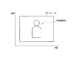
図2は、手ぶれ量検出部で検出する角速度の軸の説明図である。
手ぶれ量検出部(角速度検出部)30は、上記手ぶれ量を検出する手ぶれ量検出手段として機能するものである。具体的には、手ぶれ量検出部30は、図2に示すように、フレーム70の高さ方向(以下、X軸と定義する)の移動と横方向(以下、Y軸と定義する)の移動とのそれぞれの角速度を個別に検出すべく、図1に示したように、X軸ジャイロセンサ31およびY軸ジャイロセンサ32の2つのジャイロセンサ31、32を有し、それぞれのジャイロセンサ31、32が角速度に応じた電圧値の角速度検出信号を制御部10に出力する。
制御部10は、フレーム70のサンプリング周期と同期して各ジャイロセンサ31、32の角速度検出信号を取り込み、X軸およびY軸のそれぞれについて手ぶれ量を算出しフレーム70の画像データと対応付けて、或いは、画像データに付加してリムーバブルメディア50に格納する。
FIG. 2 is an explanatory diagram of an axis of angular velocity detected by the camera shake amount detection unit.
The camera shake amount detection unit (angular velocity detection unit) 30 functions as a camera shake amount detection unit that detects the camera shake amount. Specifically, as shown in FIG. 2, the camera shake
The
本実施形態においては、ジャイロセンサ31、32を用い、所定のサンプリング期間における積分角速度、ひいては、所定のサンプリング期間における手ぶれ量θ(X軸方向手ぶれ量θxおよびY軸方向手ぶれ量θy)を算出しているが、ジャイロセンサ31、32の個体差等によって角速度(rad/秒)がゼロの場合の角速度検出信号の電圧値が異なるため、本実施形態では、本体の電源が投入された後、撮影を開始する前までに、各ジャイロセンサ31、32の角速度検出信号をサンプリングして、その平均値をゼロ点電圧値として設定している。このとき、一定時間に亘り複数のゼロ点電圧値を求め、これらのゼロ点電圧値の平均値との差が所定値以下のゼロ点電圧値が一定割合(例えば99%)以上得られた場合に、そのゼロ点電圧値の平均値を実際のゼロ点電圧値として設定する構成としており、これにより本体が停止状態であるときのゼロ点電圧値を設定可能となる。
In this embodiment, the
操作部40は、ユーザによって操作される複数の操作子を有し、例えば電源ボタンや撮影開始/終了等の各種指示を入力するための操作キー等を有している。I/F部51は本スチルカメラ1をパーソナルコンピュータとケーブル等で通信可能に接続するためのインターフェースであり、リムーバブルメディア50に格納された画像データをパーソナルコンピュータに出力する際には当該画像データがI/F部51を介してパーソナルコンピュータに出力される。映像出力端子52は、テレビやプロジェクタなどの外部ディスプレイ装置に画像データに対応する映像信号を出力するための端子である。なお、本スチルカメラ1は、上述の構成要素の他にも、音声信号を取り込み記録・再生するためのオーディオ回路や、音声信号を外部スピーカや外部アンプ等に出力するための音声出力端子などを備えている。
The
次に動作を説明する。
図3は実施形態の処理フローチャートである。
まず、CPU11は、所定の撮影条件が満たされれば、自動的にシャッタを切るオートシャッタ機能をオンにする(ステップS11)。
次にCPU11は、シャッタスイッチが半押しされた場合には、カメラコントロール回路21を制御し、自動焦点(オートフォーカス)制御を行わせる(ステップS12)。
図4は、コントラスト検出法でオートフォーカス制御を行う場合の説明図である。
コントラスト検出法によれば、実際にレンズを駆動し、コントラストが最も高い位置を合焦点としている。すなわち、図4のレンズ位置Pが合焦点位置となるので、この位置Pで、レンズを固定しオートフォーカスロック状態とする。
続いてCPU11は、カメラコントロール回路21を制御し、自動露出制御および感度(ISO感度)設定を行わせる(ステップS13)。
そして、シャッタスイッチが全押しされた場合には、CPU11は、手ぶれ量検出部30を介して動きセンサデータであるX軸ジャイロセンサ31およびY軸ジャイロセンサ32の出力信号である角速度検出信号に基づいて動き量を取得して直近の数サンプルの動き量の平均値Xを算出する(ステップS14)。
ここで、動き量の算出について、簡単に説明すると、CPU11は、角速度検出信号に基づいて角速度(rad/秒)を算出し、この角速度(rad/秒)を所定のサンプリング間隔(秒)で積分することで積分角速度Σ(rad/秒)を算出する。実際には、制御部10は、積分角速度、すなわち、動き量として、X軸方向積分角速度ΣxおよびY軸方向積分角速度Σyを算出することとなる。
Next, the operation will be described.
FIG. 3 is a processing flowchart of the embodiment.
First, the
Next, when the shutter switch is half-pressed, the
FIG. 4 is an explanatory diagram when autofocus control is performed by the contrast detection method.
According to the contrast detection method, the lens is actually driven and the position with the highest contrast is set as the focal point. That is, since the lens position P in FIG. 4 is the in-focus position, the lens is fixed at this position P and the autofocus lock state is set.
Subsequently, the
When the shutter switch is fully pressed, the
Here, the calculation of the motion amount will be briefly described. The
続いて、CPU11は、動き量の平均値Xが基準ぶれ量Pよりも小さいか否か、すなわち、
X<P
であるか否かを判別する(ステップS15)。
ステップS15の判別において、動き量の平均値Xが基準ぶれ量Pよりも小さい、すなわち、
X<P
である場合には、自動焦点、露出および手ぶれを含む撮影条件が満たされていると見倣して、撮影処理を行う(ステップS21)。
ここで、撮影処理について説明する。
撮影処理において、CPU11は、X軸方向積分角速度ΣxおよびY軸方向積分角速度Σyに基づいてディジタルスチルカメラのパニング動作がなされたか否かを判別する。ここで、パニング動作とは、例えば、画面中央に人物を配置した状態でシャッタスイッチを半押しして、人物に対するオートフォーカスロック状態とし、つづいてディジタルスチルカメラの向きを変えて、画面の側部に人物が配置されるように構図を直す動作をいう。
Subsequently, the
X <P
It is discriminate | determined whether it is (step S15).
In the determination of step S15, the average value X of the motion amount is smaller than the reference blur amount P, that is,
X <P
If it is, it is assumed that shooting conditions including autofocus, exposure, and camera shake are satisfied, and shooting processing is performed (step S21).
Here, the photographing process will be described.
In the photographing process, the
パニング動作の判別において、ディジタルスチルカメラにおいてパニング動作がなされた場合には、手ぶれを考慮することなくオートフォーカスロック状態を維持する必要があるので、直ちに画像データ取込処理に移行し、ステップS12におけるオートフォーカス制御によりオートフォーカスロック状態とされた合焦点位置にレンズを固定して、撮影カメラ22により撮像を行い、得られた画像データを撮影部RAM23に一時的に取り込むとともに、制御部10の制御下でリムーバブルメディア50に記録する、画像データ取込処理を行うこととなる。そして、画像データのリムーバブルメディア50への記録動作と並行して表示パネル24には、撮像した画像が表示されることとなる。
ステップS15の判別において、動き量の平均値Xが基準ぶれ量P以上である場合、すなわち、
X≧P
である場合には、いまだ撮影条件が満たされていないとして、CPU11は、動き量の平均値Xが手ぶれ量を再確認するか否かを判別するために、データ再取得ぶれ量Q(>P)よりも小さいか否か、すなわち、
X<Q
であるか否かを判別する(ステップS16)。
In the panning operation determination, when the panning operation is performed in the digital still camera, it is necessary to maintain the autofocus lock state without considering camera shake, so the process immediately proceeds to the image data capturing process, and in step S12 The lens is fixed at the in-focus position where the autofocus lock is set by the autofocus control, the image is taken by the photographing
In the determination in step S15, when the average value X of the motion amount is equal to or larger than the reference blur amount P, that is,
X ≧ P
In this case, assuming that the photographing condition is not yet satisfied, the
X <Q
It is determined whether or not (step S16).
ステップS16の判別において、動き量の平均値Xがデータ再取得ぶれ量Qよりも小さい、すなわち、
X<Q
である場合には、処理を再び、ステップS14に移行し、CPU11は、手ぶれ量検出部30を介して動きセンサデータであるX軸ジャイロセンサ31およびY軸ジャイロセンサ32の出力信号である角速度検出信号に基づいて動き量を取得して直近の数サンプルの動き量の平均値Xを算出して、処理をステップS15に移行する。
ステップS16の判別において、動き量の平均値Xがデータ再取得ぶれ量Q以上である場合、すなわち、
X≧Q
である場合には、オートフォーカスのずれの影響を補正により回避できるかを判別すべく、CPU11は、動き量の平均値XがAF補正ぶれ量R1(>Q>P)よりも小さいか否か、すなわち、
X<R1
であるか否かを判別する(ステップS17)。
ステップS17の判別において、動き量の平均値XがAF補正ぶれ量R1よりも小さい、すなわち、
X<R1
である場合には、オートフォーカス補正処理に移行する(ステップS20)。
In the determination in step S16, the average value X of the motion amount is smaller than the data reacquisition blur amount Q, that is,
X <Q
If YES in step S14, the process returns to step S14, and the
In the determination of step S16, when the average value X of the motion amount is equal to or greater than the data reacquisition blur amount Q, that is,
X ≧ Q
If it is, the
X <R1
It is discriminate | determined whether it is (step S17).
In the determination in step S17, the average value X of the motion amount is smaller than the AF correction blur amount R1, that is,
X <R1
If YES, the process shifts to an autofocus correction process (step S20).
ここでオートフォーカス補正処理について説明する。
図5は、オートフォーカス補正処理の原理説明図である。
図5に示すように、手ぶれがない場合の合焦点位置Pおよび手ぶれが生じた場合の合焦点位置P1との差DFと、ディジタルスチルカメラ11のCCDの手ぶれに起因する移動量DXと、の間には、相関関係がある。従って、ディジタルスチルカメラ11の手ぶれに起因する移動量DXが検出できれば、合焦点位置を位置Pから位置P1に補正することができるはずである。
Here, the autofocus correction process will be described.
FIG. 5 is a diagram for explaining the principle of autofocus correction processing.
As shown in FIG. 5, the difference DF between the in-focus position P when there is no camera shake and the in-focus position P1 when camera shake occurs, and the movement amount DX caused by the camera shake of the CCD of the digital
図6は、X軸方向におけるオートフォーカス補正処理の説明図である。
図7は、Y軸方向におけるオートフォーカス補正処理の説明図である。
オートフォーカス補正処理において、CPU11は、算出したX軸方向手ぶれ量θxおよびY軸方向手ぶれ量θyに基づいてオートフォーカス補正量ΔLを算出する。
具体的には、まず、図6に示すように、Y軸方向手ぶれ量θyに基づいてY軸方向のオートフォーカス補正量ΔLyを次式により算出する。
ΔLy=L−L/cosθy
この結果、Y軸方向についてのみ手ぶれ量を補正した見かけ上の被写体OB1までの距離L1は次式の通りとなる。
L1=L+ΔLy
FIG. 6 is an explanatory diagram of the autofocus correction process in the X-axis direction.
FIG. 7 is an explanatory diagram of autofocus correction processing in the Y-axis direction.
In the autofocus correction process, the
Specifically, first, as shown in FIG. 6, the autofocus correction amount ΔLy in the Y-axis direction is calculated by the following equation based on the Y-axis direction camera shake amount θy.
ΔLy = L−L / cos θy
As a result, the apparent distance L1 to the subject OB1 in which the camera shake amount is corrected only in the Y-axis direction is expressed by the following equation.
L1 = L + ΔLy
続いてCPU11は、図7に示すように、X軸方向手ぶれ量θxおよび見かけ上の被写体OB1までの距離L1に基づいてX軸方向のオートフォーカス補正量ΔLxを次式により算出する。
ΔLx=L1−L1/cosθx
これらの結果に基づいて、CPU11は、オートフォーカス補正量ΔLを算出する。
ΔL=ΔLx+ΔLy
そして、CPU11は、カメラコントロール回路21を制御し、オートフォーカス補正量ΔLに基づいて、オートフォーカス補正処理を行わせ、ステップS13で求めた合焦点位置からオートフォーカス補正量ΔLだけずらした位置を新たな合焦点位置とし、撮影処理に移行する(ステップS21)。
Subsequently, as shown in FIG. 7, the
ΔLx = L1-L1 / cos θx
Based on these results, the
ΔL = ΔLx + ΔLy
Then, the
そして、ステップS20におけるオートフォーカス補正処理によりオートフォーカスロック状態とされた新たな合焦点位置にレンズを固定して、撮影カメラ22により撮像を行い、得られた画像データを撮影部RAM23に一時的に取り込むとともに、制御部10の制御下でリムーバブルメディア50に記録する、画像データ取込処理を行うこととなる。そして、画像データのリムーバブルメディア50への記録動作と並行して表示パネル24には、撮像した画像が表示されることとなる。
ステップS17の判別において、動き量の平均値XがAF補正ぶれ量R1以上、すなわち、
X≧R1
である場合には、オートフォーカス制御をやり直すべきかを判別すべく、CPU11は、動き量の平均値XがAF再決定ぶれ量R2 (>R1>Q>P)よりも小さいか否か、すなわち、
X<R2
であるか否かを判別する(ステップS18)。
Then, the lens is fixed at a new in-focus position that has been brought into the autofocus locked state by the autofocus correction process in step S20, and the image is captured by the photographing
In the determination in step S17, the average value X of the motion amount is not less than the AF correction blur amount R1, that is,
X ≧ R1
If it is, in order to determine whether or not the autofocus control should be redone, the
X <R2
It is discriminate | determined whether it is (step S18).
ステップS17の判別において、動き量の平均値XがAF再決定ぶれ量R2 よりも小さい、すなわち、
X<R2
である場合には、再び、処理をステップS12に移行し、以下同様の処理を行う。
また、ステップS17の判別において、動き量の平均値XがAF再決定ぶれ量R2 以上、すなわち、
X≧R2
である場合には、オートシャッタ機能を利用した撮影は困難であるので、CPU11は、オートシャッタ機能をオフにして処理を終了する(ステップS19)。
以上の説明のように、本実施形態によれば、オートフォーカス(自動焦点位置)、露出、手ぶれなどに基づいて撮影が可能となる撮影条件が実際の撮影時に満たされたかを判別して、自動的にシャッタを切るようにできる。さらに、オートシャッタ機能を用いる場合にオートフォーカス後の手ぶれについても自動的に補正することができ、よりピントの合った画像を得ることが可能となる。
In the determination in step S17, the average value X of the motion amount is smaller than the AF redetermination blur amount R2, that is,
X <R2
If so, the process again proceeds to step S12, and the same process is performed thereafter.
In the determination in step S17, the average value X of the motion amount is not less than the AF redetermination blur amount R2, that is,
X ≧ R2
In this case, since shooting using the auto shutter function is difficult, the
As described above, according to the present embodiment, it is automatically determined by determining whether or not shooting conditions that enable shooting based on autofocus (automatic focus position), exposure, and camera shake are satisfied during actual shooting. The shutter can be released automatically. Furthermore, when the auto shutter function is used, camera shake after autofocus can be automatically corrected, and a more focused image can be obtained.
以上の説明では、合焦点位置の検出にコントラスト検出法を用いた場合について説明したが、オートフォーカス位置の検出方法としては、様々な方法用いることが可能である。すなわち、レーダーと同様の原理で、対象物(被写体)に赤外線・超音波などを照射し、その反射波が戻るまでの時間や照射角度により距離を検出するアクティブ検出法や、位相差検出法などのパッシブ検出法も適用が可能である。
以上の説明では、動きセンサであるジャイロセンサについては、常時駆動されていることを前提にして説明したが、撮影の際の構図が決定したか否かを、例えば、複数フレーム間の相互相関度に基づいて判別させ、構図が決定した場合に、動きセンサであるジャイロセンサに電源を供給し、あるいは、動作周波数を高くするように構成することも可能である。このような構成を採ることにより、消費電力の低減が図れる。
以上の説明では、常にオートシャッタモードで動作を開始する場合について説明したが、上述した方法などにより撮影の際の構造が決定した場合に、オートシャッタモードに移行するように構成することも可能である。
以上の説明ではディジタルスチルカメラについて説明したが、携帯電話に設けられたカメ
ラや、PDA一体型カメラや、一眼レフカメラなど他の静止画を撮像可能な電子光学機器に適用が可能である。
以上の説明では、角速度に基づいてぶれ量を検出する構成を例示したが、これに限らず、加速度センサを用いてぶれ量(動き量)を検出する構成としても良い。
In the above description, the case where the contrast detection method is used to detect the in-focus position has been described, but various methods can be used as the autofocus position detection method. In other words, an active detection method that detects the distance based on the time until the reflected wave returns and the irradiation angle based on the same principle as a radar, and a phase difference detection method. This passive detection method can also be applied.
In the above description, the gyro sensor, which is a motion sensor, has been described on the assumption that it is always driven, but whether or not the composition at the time of shooting is determined, for example, the degree of cross-correlation between multiple frames When the composition is determined based on the above, it is possible to supply power to the gyro sensor which is a motion sensor or to increase the operating frequency. By adopting such a configuration, power consumption can be reduced.
In the above description, the case where the operation is always started in the auto shutter mode has been described. However, when the structure at the time of shooting is determined by the above-described method or the like, the auto shutter mode can be configured. is there.
In the above description, the digital still camera has been described. However, the present invention can be applied to other optical images such as a camera provided in a mobile phone, a PDA integrated camera, and a single-lens reflex camera.
In the above description, the configuration in which the shake amount is detected based on the angular velocity is illustrated, but the configuration is not limited thereto, and a configuration in which the shake amount (motion amount) is detected using an acceleration sensor may be employed.
1…ディジタルスチルカメラ、10…制御部(手ぶれ量検出部、オートシャッタ動作部、オートシャッタ解除部)、11…CPU(手ぶれ量検出部、オートシャッタ動作部、オートシャッタ解除部)、20…撮影部、21…カメラコントロール回路(オートフォーカス補正部)、22…撮影カメラ(オートフォーカス機構部)、24…表示パネル、30…手ぶれ量検出部(角速度検出部)、50…リムーバブルメディア、60…記録媒体、70…フレーム。
DESCRIPTION OF
Claims (4)
前記手ぶれ量を含む所定の撮影条件が満たされたか否かを判別する撮影条件判別部と、
前記撮影条件が満たされたときに自動的にシャッタを切って撮影処理するオートシャッター機能をオンするオートシャッタ動作部と、
被写体に自動的に焦点を合わせ、レンズを合焦点位置に駆動するオートフォーカス機構部と、
前記オートシャッター機能がオンのときに、前記レンズの光軸方向の手ぶれ量に基づいて前記合焦点位置を補正し、当該補正後の合焦点位置に前記レンズを駆動させるべく補正制御を行うオートフォーカス補正部と、
前記オートフォーカス補正部によりオートフォーカス制御が行われた後に、手ぶれ量を取得し、前記手ぶれ量がオートシャッター機能を利用した撮影が困難なことを示すオートフォーカス再決定ぶれ量よりも大きいか否かを判別し、前記手ぶれ量が所定のオートフォーカス再決定ぶれ量よりも大きい場合に、前記オートシャッター機能をオフするオートシャッタ解除部と、
前記手ぶれ量が所定のオートフォーカス再決定ぶれ量よりも小さい場合に、前記オートフォーカス機構部に再度前記レンズを新たな合焦点位置に駆動させるオートフォーカス再設定制御部と、を備え、
前記オートシャッタ解除部による前記手ぶれ量と前記オートフォーカス再決定ぶれ量との比較に先だって、手ぶれ量が所定のデータ再取得ぶれ量よりも大きいか否かを判別し、手ぶれ量が所定のデータ再取得ぶれ量よりも小さい場合に、再度前記手ぶれ量検出部に前記手ぶれ量を再検出させ、手ぶれ量が所定のデータ再取得ぶれ量よりも大きい場合であって、オートフォーカスのずれを補正可能であることを示すオートフォーカス補正ぶれ量よりも小さな場合に前記オートフォーカス補正部により前記補正制御を行ってから撮影処理し、手ぶれ量が前記オートフォーカス補正ぶれ量よりも大きな場合には前記オートシャッタ解除部による前記手ぶれ量と前記オートフォーカス再決定ぶれ量との比較を行う
ことを特徴とする撮像装置。 A camera shake amount detection unit for detecting a camera shake amount;
A shooting condition determining unit that determines whether or not a predetermined shooting condition including the amount of camera shake is satisfied;
An auto shutter operation section for turning on automatically automatic shutter over function of photographing processes I off the shutter when the photographing condition is satisfied,
An auto-focus mechanism that automatically focuses on the subject and drives the lens to the in-focus position;
Wherein when the auto shutter over function is on, based on the shake amount in the optical axis direction of the lens to correct the focus position, auto-corrected control so as to drive the lens to the focus position after the correction A focus correction unit;
After autofocus control is performed by the autofocus correction unit, the amount of camera shake is acquired, and whether or not the amount of camera shake is greater than the amount of camera shake re-determined to indicate that shooting using the auto shutter function is difficult determine, when the camera shake amount is greater than a predetermined autofocus redetermined blur amount, the automatic shutter release unit to turn off the automatic shutter over capability,
An autofocus reset control unit that drives the lens to a new in-focus position again in the autofocus mechanism when the amount of camera shake is smaller than a predetermined autofocus redetermination amount;
Prior to the comparison between the camera shake amount by the auto shutter release unit and the autofocus redetermination blur amount, it is determined whether or not the camera shake amount is larger than a predetermined data re-acquisition camera shake amount. When the camera shake amount is smaller than the acquired camera shake amount, the camera shake amount detecting unit again detects the camera shake amount, and the camera shake amount is larger than a predetermined data re-acquired camera shake amount. When the amount of camera shake is smaller than the autofocus correction blur amount indicating that there is, the autofocus correction unit performs the correction control to perform shooting processing, and when the camera shake amount is larger than the autofocus correction blur amount, the auto shutter release is performed. An imaging apparatus comprising: comparing the amount of camera shake caused by a unit with the amount of shake determined again for autofocus .
前記手ぶれ量検出部は、ジャイロセンサ備え、当該ジャイロセンサが出力した角速度検出信号に基づいて前記手ぶれ量を検出することを特徴とする撮像装置。 The imaging device according to claim 1,
The imaging apparatus according to claim 1, wherein the camera shake amount detection unit includes a gyro sensor and detects the camera shake amount based on an angular velocity detection signal output from the gyro sensor.
手ぶれ量を検出する手ぶれ量検出過程と、
前記手ぶれ量を含む所定の撮影条件が満たされたか否かを判別する撮影条件判別過程と、
前記撮影条件が満たされたときに自動的にシャッタを切って撮影処理するオートシャッター機能をオンするオートシャッタ動作過程と、
前記オートシャッター機能がオンのときに、前記レンズの光軸方向の手ぶれ量に基づいて前記合焦点位置を補正し、当該補正後の合焦点位置に前記レンズを駆動させるべく補正制御を行うオートフォーカス補正過程と、
前記オートフォーカス補正過程によりオートフォーカス制御が行われた後に、手ぶれ量を取得し、前記手ぶれ量がオートシャッター機能を利用した撮影が困難なことを示すオートフォーカス再決定ぶれ量よりも大きいか否かを判別し、前記手ぶれ量が所定のオートフォーカス再決定ぶれ量よりも大きい場合に、前記オートシャッター機能をオフするオートシャッタ解除過程と、
前記手ぶれ量が所定のオートフォーカス再決定ぶれ量よりも小さい場合に、前記オートフォーカス機構部に再度前記レンズを新たな合焦点位置に駆動させるオートフォーカス再設定制御過程と、を備え、
前記オートシャッタ解除過程による前記手ぶれ量と前記オートフォーカス再決定ぶれ量との比較に先だって、手ぶれ量が所定のデータ再取得ぶれ量よりも大きいか否かを判別し、手ぶれ量が所定のデータ再取得ぶれ量よりも小さい場合に、再度前記手ぶれ量検出過程により前記手ぶれ量を再検出を行い、手ぶれ量が所定のデータ再取得ぶれ量よりも大きい場合であって、オートフォーカスのずれを補正可能であることを示すオートフォーカス補正ぶれ量よりも小さな場合に前記オートフォーカス補正過程により前記補正制御を行ってから撮影処理し、手ぶれ量が前記オートフォーカス補正ぶれ量よりも大きな場合には前記オートシャッタ解除過程による前記手ぶれ量と前記オートフォーカス再決定ぶれ量との比較を行う
ことを特徴とする撮像装置の制御方法。 In a control method for an imaging apparatus, comprising: a camera shake correction mechanism that performs camera shake correction on an image captured based on a camera shake amount; and an autofocus mechanism that automatically focuses the subject and drives the lens to a focal position ,
Camera shake amount detection process for detecting the amount of camera shake,
A shooting condition determination process for determining whether or not a predetermined shooting condition including the amount of camera shake is satisfied;
An auto shutter operation process of turning on the automatic shutter over function automatically shooting process I off the shutter when the photographing condition is satisfied,
Wherein when the auto shutter over function is on, based on the shake amount in the optical axis direction of the lens to correct the focus position, auto-corrected control so as to drive the lens to the focus position after the correction Focus correction process,
After autofocus control is performed by the autofocus correction process, the amount of camera shake is acquired, and whether or not the amount of camera shake is larger than the autofocus redetermination blur amount indicating that shooting using the auto shutter function is difficult determine, when the camera shake amount is greater than a predetermined autofocus redetermined blur amount, the automatic shutter release process of turning off the automatic shutter over capability,
An autofocus reset control process for driving the lens to a new in-focus position again in the autofocus mechanism when the amount of camera shake is smaller than a predetermined autofocus redetermination amount;
Prior to comparing the camera shake amount in the auto-shutter release process with the autofocus redetermination shake amount, it is determined whether or not the camera shake amount is larger than a predetermined data re-acquisition camera shake amount, When the camera shake amount is smaller than the acquired camera shake amount, the camera shake amount is detected again by the camera shake amount detection process, and the camera shake amount is larger than the predetermined data re-acquired camera shake amount. If the amount of camera shake is smaller than the autofocus correction blur amount, the image is processed after the correction control is performed by the autofocus correction process. If the camera shake amount is larger than the autofocus correction blur amount, the auto shutter imaging and performing the camera shake amount by releasing process and a comparison of the autofocus redetermination shake amount Method of controlling the location.
前記撮像装置を、
前記手ぶれ量を含む所定の撮影条件が満たされたか否かを判別する撮影条件判別手段、
前記撮影条件が満たされたときに自動的にシャッタを切って撮影処理するオートシャッター機能をオンするオートシャッタ動作手段、
前記オートシャッター機能がオンのときに、前記レンズの光軸方向の手ぶれ量に基づいて前記合焦点位置を補正し、当該補正後の合焦点位置に前記レンズを駆動させるべく補正制御を行うオートフォーカス補正手段、
前記オートフォーカス補正部によりオートフォーカス制御が行われた後に、手ぶれ量を取得し、前記手ぶれ量がオートシャッター機能を利用した撮影が困難なことを示すオートフォーカス再決定ぶれ量よりも大きいか否かを判別し、前記手ぶれ量が所定のオートフォーカス再決定ぶれ量よりも大きい場合に、前記オートシャッター機能をオフするオートシャッタ解除手段、
前記手ぶれ量が所定のオートフォーカス再決定ぶれ量よりも小さい場合に、前記オートフォーカス機構部に再度前記レンズを新たな合焦点位置に駆動させるオートフォーカス再設定制御手段として機能させるとともに、
前記オートシャッタ解除手段による前記手ぶれ量と前記オートフォーカス再決定ぶれ量との比較に先だって、手ぶれ量が所定のデータ再取得ぶれ量よりも大きいか否かを判別し、手ぶれ量が所定のデータ再取得ぶれ量よりも小さい場合に、再度前記手ぶれ量検出装置に前記手ぶれ量を再検出させ、手ぶれ量が所定のデータ再取得ぶれ量よりも大きい場合であって、オートフォーカスのずれを補正可能であることを示すオートフォーカス補正ぶれ量よりも小さな場合に前記オートフォーカス補正部により前記補正制御を行ってから撮影処理し、手ぶれ量が前記オートフォーカス補正ぶれ量よりも大きな場合には前記オートシャッタ解除部による前記手ぶれ量と前記オートフォーカス再決定ぶれ量との比較を行う手段
として機能させることを特徴とする制御プログラム。 A camera shake detection device that detects camera shake, a camera shake correction mechanism that performs camera shake correction on images captured based on the camera shake detected, and autofocus that automatically focuses the subject and drives the lens to the in-focus position in the control program for controlling the image pickup apparatus having a mechanism portion,
The imaging device;
Imaging condition determination means for determining whether or not a predetermined imaging condition including the amount of camera shake is satisfied,
Automatic shutter operating means for turning on automatically automatic shutter over function of photographing processes I off the shutter when the photographing condition is satisfied,
Wherein when the auto shutter over function is on, based on the shake amount in the optical axis direction of the lens to correct the focus position, auto-corrected control so as to drive the lens to the focus position after the correction Focus correction means,
After the autofocus control is performed by the autofocus correction unit, the amount of camera shake is acquired, and whether or not the amount of camera shake is greater than the amount of camera shake re-determined to indicate that shooting using the auto shutter function is difficult determine, wherein when the camera shake amount is greater than a predetermined autofocus redetermined blur amount, automatic shutter release means for turning off the automatic shutter over capability,
When the camera shake amount is smaller than a predetermined autofocus redetermination blur amount, the autofocus mechanism unit functions as an autofocus reset control unit that drives the lens to a new in-focus position again.
Prior to the comparison between the camera shake amount by the auto shutter release means and the autofocus redetermination blur amount, it is determined whether or not the camera shake amount is larger than a predetermined data re-acquisition blur amount. When the amount of camera shake is smaller than the acquired amount of camera shake, the camera shake amount detection device again detects the amount of camera shake, and the amount of camera shake is larger than the predetermined amount of data re-acquired camera shake, and the shift of autofocus can be corrected. When the amount of camera shake is smaller than the autofocus correction blur amount indicating that there is, the autofocus correction unit performs the correction control to perform shooting processing, and when the camera shake amount is larger than the autofocus correction blur amount, the auto shutter release is performed. Means for comparing the amount of camera shake caused by a portion and the amount of camera shake determined again
A control program characterized by functioning as
Priority Applications (2)
| Application Number | Priority Date | Filing Date | Title |
|---|---|---|---|
| JP2006004542A JP4670647B2 (en) | 2006-01-12 | 2006-01-12 | Imaging apparatus, control method, and control program |
| US11/617,223 US7693406B2 (en) | 2005-12-28 | 2006-12-28 | Image capturing apparatus, method of controlling the same, and storage medium |
Applications Claiming Priority (1)
| Application Number | Priority Date | Filing Date | Title |
|---|---|---|---|
| JP2006004542A JP4670647B2 (en) | 2006-01-12 | 2006-01-12 | Imaging apparatus, control method, and control program |
Publications (3)
| Publication Number | Publication Date |
|---|---|
| JP2007189384A JP2007189384A (en) | 2007-07-26 |
| JP2007189384A5 JP2007189384A5 (en) | 2009-01-08 |
| JP4670647B2 true JP4670647B2 (en) | 2011-04-13 |
Family
ID=38344266
Family Applications (1)
| Application Number | Title | Priority Date | Filing Date |
|---|---|---|---|
| JP2006004542A Active JP4670647B2 (en) | 2005-12-28 | 2006-01-12 | Imaging apparatus, control method, and control program |
Country Status (1)
| Country | Link |
|---|---|
| JP (1) | JP4670647B2 (en) |
Families Citing this family (4)
| Publication number | Priority date | Publication date | Assignee | Title |
|---|---|---|---|---|
| JP4605217B2 (en) | 2007-12-28 | 2011-01-05 | カシオ計算機株式会社 | Imaging apparatus and program thereof |
| JP4986175B2 (en) * | 2007-12-28 | 2012-07-25 | カシオ計算機株式会社 | Imaging apparatus and program |
| US9282306B2 (en) | 2011-03-15 | 2016-03-08 | Nec Corporation | Imaging device, information processing device, and non-transitory computer readable medium storing program |
| CN112601011B (en) * | 2020-12-07 | 2022-12-02 | 广东省电信规划设计院有限公司 | Automatic shooting control method and control device thereof |
Citations (3)
| Publication number | Priority date | Publication date | Assignee | Title |
|---|---|---|---|---|
| JP2000193878A (en) * | 1998-12-25 | 2000-07-14 | Canon Inc | Camera |
| JP2001235782A (en) * | 2000-02-23 | 2001-08-31 | Olympus Optical Co Ltd | Camera with automatic releasing function |
| JP2001245199A (en) * | 2000-02-25 | 2001-09-07 | Ricoh Co Ltd | Apparatus for preventing camera shake |
-
2006
- 2006-01-12 JP JP2006004542A patent/JP4670647B2/en active Active
Patent Citations (3)
| Publication number | Priority date | Publication date | Assignee | Title |
|---|---|---|---|---|
| JP2000193878A (en) * | 1998-12-25 | 2000-07-14 | Canon Inc | Camera |
| JP2001235782A (en) * | 2000-02-23 | 2001-08-31 | Olympus Optical Co Ltd | Camera with automatic releasing function |
| JP2001245199A (en) * | 2000-02-25 | 2001-09-07 | Ricoh Co Ltd | Apparatus for preventing camera shake |
Also Published As
| Publication number | Publication date |
|---|---|
| JP2007189384A (en) | 2007-07-26 |
Similar Documents
| Publication | Publication Date | Title |
|---|---|---|
| US7693406B2 (en) | Image capturing apparatus, method of controlling the same, and storage medium | |
| US7634178B2 (en) | Image stabilizing apparatus and image pickup apparatus | |
| JP4994756B2 (en) | Anti-vibration control device, optical apparatus including the same, imaging device, and control method of anti-vibration control device | |
| CN109417593B (en) | Imaging device, operation method, image processing device, and image processing method | |
| JP4341613B2 (en) | Control apparatus, photographing apparatus, photographing apparatus control method, and control program | |
| US7907205B2 (en) | Optical apparatus with unit for correcting blur of captured image caused by displacement of optical apparatus in optical-axis direction | |
| KR101663225B1 (en) | Method and Apparatus for processing digital image | |
| JP2008288975A (en) | Imaging apparatus, imaging method and imaging program | |
| JP2007139952A (en) | Imaging apparatus | |
| WO2013021728A1 (en) | Imaging device and imaging method | |
| JP2005215388A (en) | Interchangeable lens and camera system using the same | |
| JP4876550B2 (en) | Imaging apparatus, control method, and control program | |
| JP4670647B2 (en) | Imaging apparatus, control method, and control program | |
| JP2010271379A (en) | Imaging device | |
| JP2003107338A (en) | Auto-focusing device | |
| JP2013104921A (en) | Image pickup apparatus, image pickup system, and control method of image pickup apparatus | |
| JP2007147804A (en) | Moving picture taking device, control method and control program | |
| WO2017086300A1 (en) | Imaging device and control method therefor, and operation program | |
| JP2009053226A (en) | Photographing system and digital camera | |
| JP2007199182A (en) | Camera with vibration-proof function | |
| JP4905048B2 (en) | IMAGING DEVICE, IMAGING DEVICE CONTROL METHOD, AND CONTROL PROGRAM | |
| JP6395401B2 (en) | Image shake correction apparatus, control method therefor, optical apparatus, and imaging apparatus | |
| JP2007180990A (en) | Imaging apparatus, control method, and control program | |
| JP2007028163A (en) | Display device of electronic camera | |
| JP2007248672A (en) | Photographic device, control method and control program |
Legal Events
| Date | Code | Title | Description |
|---|---|---|---|
| A521 | Request for written amendment filed |
Free format text: JAPANESE INTERMEDIATE CODE: A523 Effective date: 20081118 |
|
| A621 | Written request for application examination |
Free format text: JAPANESE INTERMEDIATE CODE: A621 Effective date: 20081118 |
|
| A977 | Report on retrieval |
Free format text: JAPANESE INTERMEDIATE CODE: A971007 Effective date: 20100830 |
|
| A131 | Notification of reasons for refusal |
Free format text: JAPANESE INTERMEDIATE CODE: A131 Effective date: 20100907 |
|
| A521 | Request for written amendment filed |
Free format text: JAPANESE INTERMEDIATE CODE: A523 Effective date: 20101108 |
|
| RD02 | Notification of acceptance of power of attorney |
Free format text: JAPANESE INTERMEDIATE CODE: A7422 Effective date: 20101108 |
|
| TRDD | Decision of grant or rejection written | ||
| A01 | Written decision to grant a patent or to grant a registration (utility model) |
Free format text: JAPANESE INTERMEDIATE CODE: A01 Effective date: 20101221 |
|
| A01 | Written decision to grant a patent or to grant a registration (utility model) |
Free format text: JAPANESE INTERMEDIATE CODE: A01 |
|
| A61 | First payment of annual fees (during grant procedure) |
Free format text: JAPANESE INTERMEDIATE CODE: A61 Effective date: 20110103 |
|
| R150 | Certificate of patent or registration of utility model |
Ref document number: 4670647 Country of ref document: JP Free format text: JAPANESE INTERMEDIATE CODE: R150 Free format text: JAPANESE INTERMEDIATE CODE: R150 |
|
| FPAY | Renewal fee payment (event date is renewal date of database) |
Free format text: PAYMENT UNTIL: 20140128 Year of fee payment: 3 |
|
| S531 | Written request for registration of change of domicile |
Free format text: JAPANESE INTERMEDIATE CODE: R313531 |
|
| R350 | Written notification of registration of transfer |
Free format text: JAPANESE INTERMEDIATE CODE: R350 |
|
| R250 | Receipt of annual fees |
Free format text: JAPANESE INTERMEDIATE CODE: R250 |
|
| R250 | Receipt of annual fees |
Free format text: JAPANESE INTERMEDIATE CODE: R250 |
|
| R250 | Receipt of annual fees |
Free format text: JAPANESE INTERMEDIATE CODE: R250 |
|
| R250 | Receipt of annual fees |
Free format text: JAPANESE INTERMEDIATE CODE: R250 |
|
| R250 | Receipt of annual fees |
Free format text: JAPANESE INTERMEDIATE CODE: R250 |
|
| R250 | Receipt of annual fees |
Free format text: JAPANESE INTERMEDIATE CODE: R250 |