JP4661868B2 - Ultrasonic sensor - Google Patents
Ultrasonic sensor Download PDFInfo
- Publication number
- JP4661868B2 JP4661868B2 JP2007534322A JP2007534322A JP4661868B2 JP 4661868 B2 JP4661868 B2 JP 4661868B2 JP 2007534322 A JP2007534322 A JP 2007534322A JP 2007534322 A JP2007534322 A JP 2007534322A JP 4661868 B2 JP4661868 B2 JP 4661868B2
- Authority
- JP
- Japan
- Prior art keywords
- ultrasonic sensor
- case
- substrate
- cushion member
- terminal
- Prior art date
- Legal status (The legal status is an assumption and is not a legal conclusion. Google has not performed a legal analysis and makes no representation as to the accuracy of the status listed.)
- Active
Links
- 239000000758 substrate Substances 0.000 claims description 57
- 239000000945 filler Substances 0.000 claims description 6
- 239000011347 resin Substances 0.000 description 22
- 229920005989 resin Polymers 0.000 description 22
- WABPQHHGFIMREM-UHFFFAOYSA-N lead(0) Chemical compound [Pb] WABPQHHGFIMREM-UHFFFAOYSA-N 0.000 description 16
- 239000011358 absorbing material Substances 0.000 description 14
- 239000000853 adhesive Substances 0.000 description 7
- 230000001070 adhesive effect Effects 0.000 description 7
- RYGMFSIKBFXOCR-UHFFFAOYSA-N Copper Chemical compound [Cu] RYGMFSIKBFXOCR-UHFFFAOYSA-N 0.000 description 5
- 239000000463 material Substances 0.000 description 5
- 229920002635 polyurethane Polymers 0.000 description 5
- 239000004814 polyurethane Substances 0.000 description 5
- 229920002379 silicone rubber Polymers 0.000 description 5
- XUIMIQQOPSSXEZ-UHFFFAOYSA-N Silicon Chemical compound [Si] XUIMIQQOPSSXEZ-UHFFFAOYSA-N 0.000 description 4
- 229910052710 silicon Inorganic materials 0.000 description 4
- 239000010703 silicon Substances 0.000 description 4
- 239000003566 sealing material Substances 0.000 description 3
- 239000002210 silicon-based material Substances 0.000 description 3
- 239000004593 Epoxy Substances 0.000 description 2
- 229910052782 aluminium Inorganic materials 0.000 description 2
- XAGFODPZIPBFFR-UHFFFAOYSA-N aluminium Chemical compound [Al] XAGFODPZIPBFFR-UHFFFAOYSA-N 0.000 description 2
- 230000004888 barrier function Effects 0.000 description 2
- 230000000694 effects Effects 0.000 description 2
- 239000011521 glass Substances 0.000 description 2
- 238000000034 method Methods 0.000 description 2
- 230000009471 action Effects 0.000 description 1
- 238000013016 damping Methods 0.000 description 1
- 238000001514 detection method Methods 0.000 description 1
- 239000006260 foam Substances 0.000 description 1
- 238000005187 foaming Methods 0.000 description 1
- 238000010438 heat treatment Methods 0.000 description 1
- 230000009545 invasion Effects 0.000 description 1
- 238000004519 manufacturing process Methods 0.000 description 1
- 229910052751 metal Inorganic materials 0.000 description 1
- 239000002184 metal Substances 0.000 description 1
- 239000007769 metal material Substances 0.000 description 1
- 238000003825 pressing Methods 0.000 description 1
- 230000008569 process Effects 0.000 description 1
- 230000001105 regulatory effect Effects 0.000 description 1
- 229910000679 solder Inorganic materials 0.000 description 1
- 238000005476 soldering Methods 0.000 description 1
- 238000003466 welding Methods 0.000 description 1
Images


Classifications
-
- G—PHYSICS
- G01—MEASURING; TESTING
- G01S—RADIO DIRECTION-FINDING; RADIO NAVIGATION; DETERMINING DISTANCE OR VELOCITY BY USE OF RADIO WAVES; LOCATING OR PRESENCE-DETECTING BY USE OF THE REFLECTION OR RERADIATION OF RADIO WAVES; ANALOGOUS ARRANGEMENTS USING OTHER WAVES
- G01S7/00—Details of systems according to groups G01S13/00, G01S15/00, G01S17/00
- G01S7/52—Details of systems according to groups G01S13/00, G01S15/00, G01S17/00 of systems according to group G01S15/00
- G01S7/521—Constructional features
-
- G—PHYSICS
- G10—MUSICAL INSTRUMENTS; ACOUSTICS
- G10K—SOUND-PRODUCING DEVICES; METHODS OR DEVICES FOR PROTECTING AGAINST, OR FOR DAMPING, NOISE OR OTHER ACOUSTIC WAVES IN GENERAL; ACOUSTICS NOT OTHERWISE PROVIDED FOR
- G10K9/00—Devices in which sound is produced by vibrating a diaphragm or analogous element, e.g. fog horns, vehicle hooters or buzzers
- G10K9/12—Devices in which sound is produced by vibrating a diaphragm or analogous element, e.g. fog horns, vehicle hooters or buzzers electrically operated
- G10K9/122—Devices in which sound is produced by vibrating a diaphragm or analogous element, e.g. fog horns, vehicle hooters or buzzers electrically operated using piezoelectric driving means
-
- G—PHYSICS
- G10—MUSICAL INSTRUMENTS; ACOUSTICS
- G10K—SOUND-PRODUCING DEVICES; METHODS OR DEVICES FOR PROTECTING AGAINST, OR FOR DAMPING, NOISE OR OTHER ACOUSTIC WAVES IN GENERAL; ACOUSTICS NOT OTHERWISE PROVIDED FOR
- G10K9/00—Devices in which sound is produced by vibrating a diaphragm or analogous element, e.g. fog horns, vehicle hooters or buzzers
- G10K9/18—Details, e.g. bulbs, pumps, pistons, switches or casings
- G10K9/22—Mountings; Casings
Description
この発明は超音波センサに関し、特に、たとえば自動車のバックソナーに用いられる防滴型の超音波センサに関する。 The present invention relates to an ultrasonic sensor, and more particularly to a drip-proof ultrasonic sensor used for, for example, a back sonar of an automobile.
図12は従来の超音波センサの一例を示す図解図である。図12に示す超音波センサ1は、アルミニウムなどで形成された有底筒状のケース2を含む。ケース2の内部の底面には、圧電素子3の一方面が接合される。この圧電素子3を覆うようにして、ケース2の内部のほぼ全体に、発泡性シリコンなどの発泡性樹脂4が充填されている。さらに、発泡性樹脂4を覆うようにして、ケース2の開口部に、2つの端子5aおよび5bを有する基板6が取り付けられる。基板6の両面には、端子5aおよび5bに接続される電極7aおよび7bがそれぞれ形成される。一方の端子5aは、基板6の内側に形成された電極7aおよびワイヤ8によって圧電素子3の他方面に接続される。また、他方の端子5bは、基板6の外側に形成された電極7bおよび半田9によって、ケース2を介して圧電素子3の一方面に接続される。
FIG. 12 is an illustrative view showing one example of a conventional ultrasonic sensor. The
図12に示す超音波センサ1を用いて被検出物までの距離を測定する場合、端子5aおよび5bに駆動電圧を印加することにより、圧電素子3が励振される。圧電素子3の振動により、ケース2の底面も振動し、図12に矢印で示すように、底面に直交する向きに超音波が発せられる。超音波センサ1から発せられた超音波が被検出物で反射し、超音波センサ1に到達すると、圧電素子3が振動して電気信号に変換され、端子5aおよび5bから電気信号が出力される。したがって、駆動電圧を印加してから電気信号が出力されるまでの時間を測定することにより、超音波センサ1から被検出物までの距離を測定することができる。
When the distance to the object to be detected is measured using the
図12に示す超音波センサ1では、ケース2の内部に発泡性樹脂4が充填されていることにより、ケース2全体の振動を抑制することができる。また、発泡性樹脂4の内部に存在する多数の発泡孔によって、ケース2の内側に発生する超音波が散乱・吸収される。それにより、ケース2自体の振動、およびケース2の内部にこもる超音波の双方を効率的に抑制することができ、残響特性を改善することができる(特許文献1参照)。
In the
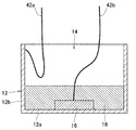
図13は従来の超音波センサの他の例を示す図解図である。図13に示す超音波センサ1は、図12に示す超音波センサ1と比べて、特に、端子5aおよび5bを有する基板6が、ケース2に直接取り付けられるのではなく、ケース2の内部に充填されているシリコンゴム等からなる弾性体4aで覆われている。さらに、弾性体4aの露出面上には、ガスバリア性の高いシリコン材からなる封止材4bが設けられている。また、一方の端子5aは、リード線8aを介して、他方の端子5bは、リード線8bおよびケース2を介して、それぞれ圧電素子3に接続されている。
FIG. 13 is an illustrative view showing another example of a conventional ultrasonic sensor. Compared to the
図13に示す超音波センサ1では、ガスバリア性の高いシリコン材からなる封止材4bが弾性体4aの露出面上に設けられているので、腐食性ガスがケース2内に侵入するのを効果的に防止することができ、さらに、封止材4bとしてシリコン材が用いられているので、温度変化が激しく低温環境下で使用されても、残響特性を十分なレベルに維持することができる(特許文献2参照)。
In the
図12に示す従来の超音波センサ1では、端子5aおよび5bを有する基板6がケース2の側面に直接接触して固定されているため、圧電素子3の振動がケース2および基板6を伝わり端子5aおよび5bからダンピングされてしまう。
In the conventional
一方、図13に示す超音波センサ1では、端子5aおよび5bを有する基板6がケース2内部に充填されているシリコンゴム等からなる弾性体4aで覆われているため、ケース2などを通じての振動のダンピングは生じにくい構造となっている。
しかしながら、図13に示す超音波センサ1では、基板6およびそれにともなう端子5aおよび5bの位置が、弾性体4aとなるシリコンゴム等の充填作業によってずれることが多く、端子5aおよび5bの位置を超音波センサにおける所定の位置に定めにくく、実装時に不具合が発生するおそれがある。On the other hand, in the
However, in the
また、図12および図13に示す各超音波センサ1では、ケース2の内部のワイヤ8やリード線8aおよび8bと端子5aおよび5bとは半田、溶接等により接合されるが、構造上接合後に基板6とケース2などを組立てるため、ワイヤ8やリード線8aおよび8bを長く形成する必要があり、また、ケース2などの組立て時にワイヤ8やリード線8aおよび8bの接合部に過大なストレスを与えてしまう可能性があり、端子5aおよび5bへの配線加工は難易度が高いものである。
Further, in each
それゆえに、この発明の主たる目的は、圧電素子の振動がダンピングされにくい構造であり、端子を所定の位置に位置決めしやすい構造であり、しかも、圧電素子と端子とを容易に接続することができる構造である、超音波センサを提供することである。 Therefore, a main object of the present invention is a structure in which the vibration of the piezoelectric element is not easily damped, a structure in which the terminal is easily positioned at a predetermined position, and the piezoelectric element and the terminal can be easily connected. It is to provide an ultrasonic sensor that is a structure.
この発明にかかる超音波センサは、有底筒状のケースと、ケースの内部の底面に形成される圧電素子と、ケースの開口側部に嵌合されるクッション部材と、クッション部材に嵌合されてクッション部材で保持され、端子が固定されている基板と、基板上に形成され、端子に電気的に接続される電極と、クッション部材の上面に形成され、ケースの内部および基板上の電極に通じる開口部とを備えた、超音波センサである。
この発明にかかる超音波センサは、たとえば、圧電素子に電気的に接続され、開口部から引き出され、基板上の電極に電気的に接続されるリード線やリードリボンなどの接続部材と、開口部からケースの内部に充填される発泡性樹脂などの充填材とを備える。
また、この発明にかかる超音波センサは、たとえば、クッション部材と端子が固定されている基板との嵌合構造は片持ち梁構造であり、片持ち梁構造の周囲に開口部が形成されることが好ましい。
さらに、この発明にかかる超音波センサでは、たとえば、クッション部材に端子に対応した貫通孔が形成され、貫通孔に端子を挿入することによって、端子が固定されている基板がクッション部材で保持されることが好ましい。An ultrasonic sensor according to the present invention is fitted to a bottomed cylindrical case, a piezoelectric element formed on a bottom surface inside the case, a cushion member fitted to an opening side portion of the case, and a cushion member. The substrate is held by the cushion member and the terminal is fixed, the electrode formed on the substrate and electrically connected to the terminal, the upper surface of the cushion member, and the electrode inside the case and the electrode on the substrate. It is an ultrasonic sensor provided with the opening part which leads.
The ultrasonic sensor according to the present invention includes, for example, a connecting member such as a lead wire and a lead ribbon that is electrically connected to a piezoelectric element, drawn from an opening, and electrically connected to an electrode on a substrate, and the opening. And a filler such as a foamable resin filled in the case.
In the ultrasonic sensor according to the present invention, for example, the fitting structure between the cushion member and the substrate on which the terminal is fixed is a cantilever structure, and an opening is formed around the cantilever structure. Is preferred.
Furthermore, in the ultrasonic sensor according to the present invention, for example, a through hole corresponding to the terminal is formed in the cushion member, and the substrate on which the terminal is fixed is held by the cushion member by inserting the terminal into the through hole. It is preferable.
この発明にかかる超音波センサでは、ケースに圧電素子が形成され、端子が固定されている基板がケースに嵌合されるクッション部材で保持されるので、基板がケースと直接接触することがなく、圧電素子の振動がクッション部材で緩衝され、端子に伝わりにくく、ダンピングされにくい。
また、この発明にかかる超音波センサでは、端子が固定されている基板がケースに嵌合されるクッション部材で保持されるので、端子を所定の位置に位置決めしやすい。
さらに、この発明にかかる超音波センサでは、ケースの内部および基板上の電極に通じる開口部がクッション部材の上面に形成されるので、たとえば圧電素子に電気的に接続されるリード線やリードリボンなどの接続部材を開口部から引き出して基板上の電極に電気的に接続しやすくなり、圧電素子と端子とを容易に接続することができる。
この発明にかかる超音波センサにおいて、開口部からケースの内部にたとえば発泡性樹脂などの弾性を有する充填材を充填すると、ケース全体の振動を抑制することができる。
また、この発明にかかる超音波センサにおいて、たとえば、クッション部材と端子が固定されている基板との嵌合構造を片持ち梁構造にし、片持ち梁構造の周囲に開口部を形成すると、大きな開口部を形成することができ、圧電素子と端子との接続作業や充填材の充填作業がさらに容易になる。
さらに、この発明にかかる超音波センサにおいて、たとえば、クッション部材に端子に対応した貫通孔を形成し、貫通孔に端子を挿入することによって、端子が固定されている基板をクッション部材で保持すると、端子がクッション部材で直接保持され、端子を所定の位置にさらに位置決めしやすくなる。In the ultrasonic sensor according to the present invention, the piezoelectric element is formed in the case, and the substrate on which the terminal is fixed is held by the cushion member fitted into the case, so the substrate does not directly contact the case, The vibration of the piezoelectric element is buffered by the cushion member, and is not easily transmitted to the terminal and is not easily damped.
Moreover, in the ultrasonic sensor according to the present invention, since the substrate on which the terminal is fixed is held by the cushion member fitted to the case, the terminal can be easily positioned at a predetermined position.
Furthermore, in the ultrasonic sensor according to the present invention, the opening that leads to the inside of the case and the electrode on the substrate is formed on the upper surface of the cushion member. For example, a lead wire or a lead ribbon that is electrically connected to the piezoelectric element. This connection member can be pulled out from the opening and easily connected to the electrode on the substrate, so that the piezoelectric element and the terminal can be easily connected.
In the ultrasonic sensor according to the present invention, if a filler having elasticity such as foamable resin is filled into the case from the opening, vibration of the entire case can be suppressed.
In the ultrasonic sensor according to the present invention, for example, when the fitting structure between the cushion member and the substrate on which the terminal is fixed is a cantilever structure and an opening is formed around the cantilever structure, a large opening is obtained. The portion can be formed, and the connection work between the piezoelectric element and the terminal and the filling work of the filler are further facilitated.
Furthermore, in the ultrasonic sensor according to the present invention, for example, by forming a through hole corresponding to the terminal in the cushion member and inserting the terminal into the through hole, the substrate to which the terminal is fixed is held by the cushion member. The terminal is directly held by the cushion member, which makes it easier to position the terminal at a predetermined position.
この発明によれば、圧電素子の振動がダンピングされにくい構造であり、端子を所定の位置に位置決めしやすい構造であり、しかも、圧電素子と端子とを容易に接続することができる構造である、超音波センサが得られる。 According to the present invention, the vibration of the piezoelectric element is less likely to be damped, the terminal is easily positioned at a predetermined position, and the piezoelectric element and the terminal can be easily connected. An ultrasonic sensor is obtained.
この発明の上述の目的、その他の目的、特徴および利点は、図面を参照して行う以下の発明を実施するための最良の形態の説明から一層明らかとなろう。 The above-mentioned object, other objects, features, and advantages of the present invention will become more apparent from the following description of the best mode for carrying out the invention with reference to the drawings.
10 超音波センサ
12 ケース
12a 底面部
12b 側壁
14 空洞部
16 圧電素子
18 吸音材
20 クッション部材
22 取付部
24 段差部
26、26a、26b 保持部
28a、28b 凹部
30a、30b 貫通孔
32 開口部
34、34a、34b 基板
36a、36b ピン端子
38a、38b 電極
40 吸音材
42a、42b リード線
43a、43b リードリボン
44 弾性樹脂DESCRIPTION OF
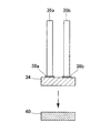
図1はこの発明にかかる超音波センサの一例を示す平面図解図であり、図2はその超音波センサの正面図解図であり、図3はその超音波センサの側面図解図であり、図4はその超音波センサの分解斜視図である。なお、図1および図4には、ケースの内部に充填される発泡性樹脂および電気的接続用のリード線を示していない。 1 is a plan view illustrating an example of an ultrasonic sensor according to the present invention, FIG. 2 is a front view illustrating the ultrasonic sensor, and FIG. 3 is a side view illustrating the ultrasonic sensor. FIG. 3 is an exploded perspective view of the ultrasonic sensor. Note that FIG. 1 and FIG. 4 do not show the foamable resin filled in the case and lead wires for electrical connection.
図1に示す超音波センサ10は、たとえば有底円筒状のケース12を含む。このケース12は、底面部12aと側壁12bとで構成される。ケース12は、たとえばアルミニウムなどの金属材料で形成される。ケース12の内側の空洞部14は、図1および図4に示すように、たとえば略楕円形状の断面形状となるように形成される。したがって、ケース12は、側壁12bの一方の対向部における壁厚が薄く形成され、それと直交する向きの対向部における壁厚が厚く形成されている。なお、空洞部14の形状によって、超音波センサ10から発せられる超音波の広がり方が決定されるため、所望の特性に応じて、空洞部14の形状が設計される。
An
ケース12の内部において、底面部12aの内面には、圧電素子16が取り付けられる。圧電素子16は、たとえば円板状の圧電体基板の両面に電極を形成したものである。そして、圧電素子16の一方面側の電極が、導電性接着剤などによって底面部12aに接着される。さらに、圧電素子16の他方面側の電極上には、接着剤によって、たとえばフェルトからなる吸音材18が接着される。吸音材18は、圧電素子16からケース12の内側へ向かう超音波を吸収するために用いられるとともに、後述の弾性樹脂44によって圧電素子16の振動が妨げられないようにする働きをする。
Inside the
ケース12の開口側部には、たとえばシリコンゴムからなるクッション部材20が嵌合される。クッション部材20は、ケース12から外部への不要な振動の伝播と外部からケース12への不要な振動の侵入とを抑える作用があり、緩衝材として用いられるものである。クッション部材20は、円筒状の取付部22を含む。取付部22は、ケース12に取り付けられるものであり、内側の高さ方向における中央に段差部24を有し、高さ方向における上半部分の内径がケース12の外径より狭く形成され、高さ方向における下半部分の内径がケース12の外径とほぼ同じ大きさに形成される。したがって、取付部22は、その下半部分をケース12の開口側部に嵌合することによって、ケース12に取り付けることができる。
A
取付部22には、その上部から中央にのびて、たとえば直方体状の保持部26が取付部22と一体的に形成される。保持部26は、後述の基板34とピン端子36aおよび36bとを保持するためのものである。保持部26の下部には、後述の基板34の一部分が嵌め込まれる凹部28aと、後述の吸音材40の一部分が嵌め込まれる凹部28bとが、階段状に形成される。この場合、凹部28aは保持部26の先端側に形成され、凹部28bは凹部28aよりも下側で凹部28aよりも取付部22側にのびて形成される。さらに、クッション部材20の略中央において、保持部26には、上下方向にのびる2つの貫通孔30aおよび30bが、保持部26の幅方向に間隔を隔てて形成される。これらの貫通孔30aおよび30bは、後述のピン端子36aおよび36bを挿入するためのものであり、ピン端子36aおよび36bに対応して形成される。
In the
また、クッション部材20の上面には、取付部22の内側であって保持部26の外側に、すなわち、保持部26などの後述の片持ち梁構造の周囲に、略C字状の開口部32が形成される。この開口部32は、後述の電極38aおよび38bにリード線42aおよび42bを電気的に接続する際やケース12の内部に弾性樹脂44を充填する際に使われるものであり、ケース12の内部や後述の基板34上の電極38aおよび38bに通じるように形成される。
Further, on the upper surface of the
クッション部材20の保持部26には、基板34とピン端子36aおよび36bとが嵌合され保持される。この基板34としては、たとえば長方形状のガラスエポキシ基板が用いられ、基板34には、2つのピン端子36aおよび36bが幅方向に間隔を隔てて圧入されて固定されている。また、基板34の上面には、2つの電極38aおよび38bが幅方向に間隔を隔てて形成され、これらの電極38aおよび38bは、ピン端子36aおよび36bに、それぞれ電気的に接続されている。
そして、ピン端子36aおよび36bが保持部26の貫通孔30aおよび30bにそれぞれ下方から挿入され、基板34の一部分が保持部26の凹部28aに嵌め込まれる。それによって、基板34とピン端子36aおよび36bとが、クッション部材20の保持部26で保持される。この場合、クッション部材20の保持部26と基板34、ピン端子36aおよび36bとの嵌合構造は片持ち梁構造であり、ピン端子36aおよび36bは、クッション部材20の略中央に位置する。The
Then, the
また、基板34の下面には、たとえばフェルトからなる長方形板状の吸音材40が接着剤で接着され、吸音材40の一部分が保持部26の凹部28bに嵌め込まれる。この吸音材40は、基板34からケース12の内側に向かう超音波を吸収するために用いられる。
In addition, a rectangular plate-like
ケース12の側壁12bの内面には、接続部材としてたとえばポリウレタン銅線からなる一方のリード線42aの一端が接続される。そのため、このリード線42aは、ケース12を介して、圧電素子16の一方面側の電極に電気的に接続される。また、リード線42aの他端は、開口部32から引き出され、基板34上の一方の電極38aに接続される。したがって、圧電素子16の一方面側の電極は、ケース12、リード線42aおよび電極38aを介して、一方のピン端子36aに電気的に接続される。
また、接続部材としてたとえばポリウレタン銅線からなる他方のリード線42bの一端が、圧電素子16の他方面側の電極に接続される。このリード線42bの他端は、開口部32から引き出され、基板34上の他方の電極38bに接続される。したがって、圧電素子16の他方面側の電極は、リード線42bおよび電極38bを介して、他方のピン端子36bに電気的に接続される。One end of one
In addition, one end of the
ケース12の内部およびクッション部材20の開口部32には、開口部32から充填材としてたとえば発泡性シリコンなどの弾性樹脂44が充填される。
The inside of the
次に、この超音波センサ10の製造方法の一例について説明する。
Next, an example of a method for manufacturing the
まず、図5に示すように、上面に電極38aおよび38bがプリント配線されかつスルーホールにピン端子36aおよび36bが圧入されて電極38aおよび38bにそれぞれ電気的に接続されたガラスエポキシ基板からなる基板34が準備される。そして、この基板34の下面には、フェルトからなる吸音材40が接着剤で接着される。
First, as shown in FIG. 5, a substrate made of a glass epoxy substrate in which
さらに、図6に示すように、取付部22および保持部26を有するシリコンゴムからなるクッション部材20が形成される。
Further, as shown in FIG. 6, a
そして、図7に示すように、クッション部材20の保持部26に形成された貫通孔30aおよび30bにピン端子36aおよび36bをそれぞれ挿入し、さらに、保持部26に形成された凹部28aおよび28bに基板34の一部分および吸音材40の一部分をそれぞれ嵌め込むことによって、基板34やピン端子36aおよび36bが、クッション部材20の保持部26に嵌合されその保持部26で保持される。
Then, as shown in FIG. 7,
また、図8に示すように、ケース12が準備され、ケース12の底面部12aの内面に圧電素子16の一方面側の電極が導電性接着剤で接着される。さらに、ポリウレタン銅線からなる一方のリード線42aの一端がケース12の側壁12bの内面に半田付けされ、ポリウレタン銅線からなる他方のリード線42bの一端が圧電素子16の他方面側の電極に半田付けされる。また、ケース12の内部において、圧電素子16の他方面側の電極上にフェルトからなる吸音材18が接着剤で接着される。
Further, as shown in FIG. 8, a
そして、図2および図3に示すように、ケース12の開口側部にクッション部材20の取付部22が嵌合され、一方のリード線42aの他端が開口部32から引き出され一方の電極38aに半田付けされ、さらに、他方のリード線42bの他端が開口部32から引き出され他方の電極38bに半田付けされる。
2 and 3, the
それから、ケース12の内部およびクッション部材20の開口部32には、充填材として発泡性シリコンなどの弾性樹脂44が充填される。なお、この場合、クッション部材20の開口部32からケース12の内部に発泡前の樹脂が注入され、それを加熱発泡硬化させることによって、弾性樹脂44が充填される。それによって、超音波センサ10が製造される。
Then, the inside of the
この超音波センサ10は、たとえば自動車のバックソナーなどとして用いられる場合、ピン端子36aおよび36bに駆動電圧を印加することにより、圧電素子16が励振される。このとき、圧電素子16の周囲が弾性樹脂44で覆われていても、圧電素子16に接着されている吸音材18によって、圧電素子16の振動領域が確保されている。圧電素子16の振動により、ケース12の底面部12aも振動し、底面部12aに直交する向きに超音波が発せられる。超音波センサ10から発せられた超音波が被検出物で反射し、超音波センサ10に到達すると、圧電素子16が振動して電気信号に変換されて、ピン端子36aおよび36bから電気信号が出力される。したがって、駆動電圧を印加してから電気信号が出力されるまでの時間を測定することにより、超音波センサ10から被検出物までの距離を測定することができる。
When this
この超音波センサ10では、ケース12の内部に弾性樹脂44が充填されているので、ケース12全体の振動を抑制することができる。
In the
また、この超音波センサ10では、ケース12からピン端子36aおよび36bへの振動の伝播などケース12とピン端子36aおよび36bとの振動干渉が、吸音材18、クッション部材20、吸音材40および弾性樹脂44で低減ないしは遮断されるため、物体検知時の残響信号や受信信号への振動漏れ信号の影響等が抑えられ、すなわち、振動漏れ等による残響特性劣化がなく、しかも、外部からピン端子36aおよび36bを経由した不要振動等の伝播の影響も抑えられる。
In the
さらに、この超音波センサ10では、ケース12に嵌合されたクッション部材20に形成された貫通孔30aおよび30bにピン端子36aおよび36bを挿入して嵌め込むので、ケース12に対するピン端子30aおよび30bの位置決め制度を向上することが可能である。すなわち、ピン端子36aおよび36bの根元部がクッション部材20に形成された貫通孔30aおよび30bに一致し、また、ケース12の中央部とクッション部材20の中央部とが一致するので、ケース12に対するピン端子36aおよび36bの位置精度として高い位置精度が得られる。
Further, in this
また、この超音波センサ10では、ケース12、クッション部材20、基板34、ピン端子36aおよび36bを、接着剤や特別な位置決め治具を必要とせず、嵌め込みなどで容易に位置精度よく組み立てることが可能である。
Further, in the
さらに、この超音波センサ10では、ケース12にクッション部材20を嵌合した後に、クッション部材20の開口部32から基板34の電極38aおよび38bにリード線42aおよび42bを半田付けすることができるので、圧電素子16とピン端子36aおよび36bとの接続作業が容易になるとともに、作業工数を削減することができる。
Further, in this
また、この超音波センサ10では、クッション部材20の上面よりピン端子36aおよび36bのみが突出するので、すなわち、ピン端子36aおよび36bなどを保持するクッション部材20の保持部26の面積が比較的狭いので、発泡性シリコンなどの弾性樹脂44の材料を充填するための開口部32の面積を比較的広く取ることができ、その材料の充填作業が容易になり、そのため、弾性樹脂44の不要な気泡の発生が抑えられ、残留特性等の品質が安定化する。
In the
さらに、この超音波センサ10では、基板34上や、基板34、ピン端子36aおよび36bを保持する保持部26の周囲にも弾性樹脂44が充填されるので、保持部26、基板34、ピン端子36aおよび36bが弾性樹脂44で補強される。
Further, in this
図9はこの発明にかかる超音波センサの他の例を示す平面図解図である。図9に示す超音波センサ10では、図1に示す超音波センサ10と比べて、クッション部材20の保持部26が短く形成されている。そのため、ピン端子36aおよび36bは、クッション部材20の中央部と取付部22との間に配置され、クッション部材20の開口部32は、より広く形成されている。
FIG. 9 is an illustrative plan view showing another example of the ultrasonic sensor according to the present invention. In the
図10はこの発明にかかる超音波センサのさらに他の例を示す平面図解図である。図10の示す超音波センサ10では、図9に示す超音波センサ10と比べて、クッション部材20が1つの保持部26の代わりに分割された2つの保持部26aおよび26bを有し、1つの基板34が2つの基板34aおよび34bに分割されるとともに、クッション部材20の開口部32が略T字状に広く形成されている。
FIG. 10 is an illustrative plan view showing still another example of the ultrasonic sensor according to the present invention. In the
図9に示す超音波センサ10および図10に示す超音波センサ10でも、図1に示す超音波センサ10と同様に効果を奏する。
また、図9に示す超音波センサ10および図10に示す超音波センサ10では、それぞれ、図1に示す超音波センサ10と比べて、クッション部材20の開口部32の大きさが大きくなるので、電極38aおよび38bへの電気的な接続や弾性樹脂44の材料の充填がさらに容易になる。The
Further, in the
図11はこの発明にかかる超音波センサのさらに他の例を示す正面図解図である。図11に示す超音波センサ10では、図1に示す超音波センサ10と比べて、接続部材としてポリウレタン銅線からなる線状のリード線42aおよび42bの代わりに金属板をプレス成形して形成した帯状のリードリボン43aおよび43bが用いられている。
図11に示す超音波センサ10でも、上述の各超音波センサ10と同様に効果を奏する。
また、図12および図13に示す従来の各超音波センサ1では、構造上、線状のワイヤ8やリード線8aおよび8bが用いられており、帯状のリードリボンを用いることが困難であるが、図11に示す超音波センサ10では、クッション部材20の開口部32から基板34上の電極38aおよび38bに配線する構造なので、帯状のリードリボン43aおよび43bを用いることができ、自動機などによる配線化が可能であり、配線の自動化等の選択肢が増える。FIG. 11 is an elevational view showing still another example of the ultrasonic sensor according to the present invention. In the
The
Further, in each of the conventional
なお、上述の各超音波センサでは各部が特定の大きさ、形状、配置、材料および数で規定されているが、この発明では、それらは任意に変更されてもよい。 In addition, although each part is prescribed | regulated by specific magnitude | size, shape, arrangement | positioning, material, and number in each above-mentioned ultrasonic sensor, in this invention, they may be changed arbitrarily.
この発明にかかる超音波センサは、たとえば、自動車のバックソナーなどに利用される。 The ultrasonic sensor according to the present invention is used, for example, in a back sonar of an automobile.
Claims (4)
前記ケースの内部の底面に形成される圧電素子、
前記ケースの開口側部に嵌合されるクッション部材、
前記クッション部材に嵌合されて前記クッション部材で保持され、端子が固定されている基板、
前記基板上に形成され、前記端子に電気的に接続される電極、および
前記クッション部材の上面に形成され、前記ケースの内部および前記基板上の前記電極に通じる開口部を備えた、超音波センサ。Bottomed cylindrical case,
A piezoelectric element formed on the bottom surface inside the case,
A cushion member fitted to the opening side of the case;
A substrate that is fitted to the cushion member and held by the cushion member, and a terminal is fixed;
An ultrasonic sensor formed on the substrate and electrically connected to the terminal, and an opening formed on an upper surface of the cushion member and leading to the inside of the case and the electrode on the substrate .
前記開口部から前記ケースの内部に充填される充填材を備えた、請求項1に記載の超音波センサ。A connecting member electrically connected to the piezoelectric element, drawn out from the opening, and electrically connected to the electrode on the substrate; and a filler filled into the case from the opening The ultrasonic sensor according to claim 1.
前記片持ち梁構造の周囲に前記開口部が形成される、請求項1または請求項2に記載の超音波センサ。The fitting structure between the cushion member and the substrate on which the terminal is fixed is a cantilever structure,
The ultrasonic sensor according to claim 1, wherein the opening is formed around the cantilever structure.
Applications Claiming Priority (3)
| Application Number | Priority Date | Filing Date | Title |
|---|---|---|---|
| JP2005262743 | 2005-09-09 | ||
| JP2005262743 | 2005-09-09 | ||
| PCT/JP2006/316555 WO2007029506A1 (en) | 2005-09-09 | 2006-08-24 | Ultrasonic sensor |
Publications (2)
| Publication Number | Publication Date |
|---|---|
| JPWO2007029506A1 JPWO2007029506A1 (en) | 2009-03-19 |
| JP4661868B2 true JP4661868B2 (en) | 2011-03-30 |
Family
ID=37835630
Family Applications (1)
| Application Number | Title | Priority Date | Filing Date |
|---|---|---|---|
| JP2007534322A Active JP4661868B2 (en) | 2005-09-09 | 2006-08-24 | Ultrasonic sensor |
Country Status (6)
| Country | Link |
|---|---|
| US (1) | US7728486B2 (en) |
| EP (1) | EP1924121A4 (en) |
| JP (1) | JP4661868B2 (en) |
| KR (1) | KR100975007B1 (en) |
| CN (1) | CN101258772B (en) |
| WO (1) | WO2007029506A1 (en) |
Cited By (2)
| Publication number | Priority date | Publication date | Assignee | Title |
|---|---|---|---|---|
| JP5548834B1 (en) * | 2014-03-11 | 2014-07-16 | 東京計装株式会社 | Ultrasonic flow meter |
| JP5580950B1 (en) * | 2014-05-16 | 2014-08-27 | 東京計装株式会社 | Ultrasonic flow meter |
Families Citing this family (34)
| Publication number | Priority date | Publication date | Assignee | Title |
|---|---|---|---|---|
| JP4222416B2 (en) * | 2004-04-26 | 2009-02-12 | 株式会社村田製作所 | Ultrasonic sensor |
| JP4193006B2 (en) * | 2005-09-09 | 2008-12-10 | 株式会社村田製作所 | Ultrasonic sensor |
| CN101385391B (en) * | 2006-02-14 | 2012-07-04 | 株式会社村田制作所 | Ultrasonic sensor and fabrication method thereof |
| DE102006050037A1 (en) * | 2006-10-24 | 2008-04-30 | Robert Bosch Gmbh | Ultrasonic transducer for motor vehicle, has damping unit for damping vibrations of wall, arranged in diaphragm pot in edge section of diaphragm and connected with edge section and inner side of wall in force-fitting manner |
| JP2008311736A (en) * | 2007-06-12 | 2008-12-25 | Mitsumi Electric Co Ltd | Ultrasonic sensor |
| AU2013206304B2 (en) * | 2008-07-16 | 2015-01-22 | Rosemount Measurement Limited | Detector and methods of detecting |
| GB0813014D0 (en) * | 2008-07-16 | 2008-08-20 | Groveley Detection Ltd | Detector and methods of detecting |
| JP5386910B2 (en) * | 2008-09-26 | 2014-01-15 | 株式会社デンソー | Electronic circuit equipment |
| EP2530953B1 (en) * | 2010-01-25 | 2018-03-14 | Murata Manufacturing Co., Ltd. | Ultrasonic vibration device |
| JP5099175B2 (en) | 2010-05-28 | 2012-12-12 | 株式会社村田製作所 | Ultrasonic sensor |
| JP5522100B2 (en) | 2010-05-28 | 2014-06-18 | 株式会社村田製作所 | Ultrasonic sensor |
| KR20130020371A (en) * | 2011-08-19 | 2013-02-27 | 삼성전기주식회사 | Ultrasonic sensor |
| KR20130021217A (en) * | 2011-08-22 | 2013-03-05 | 삼성전기주식회사 | Ultrasonic sensor |
| JP5834657B2 (en) * | 2011-09-12 | 2015-12-24 | セイコーエプソン株式会社 | Ultrasonic probe and ultrasonic diagnostic imaging apparatus |
| KR20130034877A (en) * | 2011-09-29 | 2013-04-08 | 삼성전기주식회사 | Ultrasonic wave sensor and manufacturing method thereof |
| WO2013051524A1 (en) * | 2011-10-04 | 2013-04-11 | 株式会社村田製作所 | Ultrasonic sensor and manufacturing method therefor |
| KR101491510B1 (en) * | 2011-10-05 | 2015-02-09 | 가부시키가이샤 무라타 세이사쿠쇼 | Ultrasonic sensor |
| TWI454668B (en) * | 2012-02-21 | 2014-10-01 | Tung Thih Electronic Co Ltd | Ultrasonic sensor device |
| KR101431094B1 (en) * | 2012-11-16 | 2014-08-21 | 주식회사 베어링아트 | Ultrasonic sensor and Manufacturing method thereof and Read side sensing device for vehicle |
| KR101553869B1 (en) * | 2013-07-02 | 2015-09-17 | 현대모비스 주식회사 | Ultrasonic sensor assembly |
| DE102013224196B3 (en) * | 2013-11-27 | 2014-11-20 | Robert Bosch Gmbh | Sensor device for distance measurement, in particular for a motorcycle |
| MX2017013315A (en) * | 2015-05-22 | 2018-01-25 | Halliburton Energy Services Inc | Ultrasonic transducers with piezoelectric material embedded in backing. |
| JP6592282B2 (en) * | 2015-06-12 | 2019-10-16 | アズビル株式会社 | Ultrasonic sensor |
| WO2018101865A1 (en) * | 2016-11-30 | 2018-06-07 | Saab Ab | Sonar with damping structure |
| WO2018101864A1 (en) * | 2016-11-30 | 2018-06-07 | Saab Ab | Sonar device with holder |
| EP3805753B1 (en) * | 2016-12-21 | 2022-04-27 | Honeywell International Inc. | Explosion proof piezoelectric ultrasonic detector |
| AU2017418218A1 (en) * | 2017-06-12 | 2020-02-06 | Microfine Materials Technologies Pte Ltd | Cost-effective high-bending-stiffness connector and piezoelectric actuator made of such |
| JP6863466B2 (en) * | 2017-09-21 | 2021-04-21 | 株式会社村田製作所 | Ultrasonic sensor |
| WO2020010026A1 (en) * | 2018-07-02 | 2020-01-09 | Overcast Innovations Llc | Method and system for providing a centralized appliance hub |
| CN111762098B (en) * | 2020-07-03 | 2021-07-27 | 无锡职业技术学院 | Vehicle body anti-collision alarm device and use method thereof |
| JP2022137676A (en) * | 2021-03-09 | 2022-09-22 | Tdk株式会社 | ultrasonic transducer |
| CN113093206B (en) * | 2021-03-30 | 2023-11-14 | 广东奥迪威传感科技股份有限公司 | Ultrasonic sensor |
| USD1024818S1 (en) * | 2021-04-16 | 2024-04-30 | Chengdu Huitong West Electronic Co., Ltd. | Housing of ultrasonic sensor |
| USD1024814S1 (en) * | 2022-07-05 | 2024-04-30 | Chengdu Huitong West Electronic Co., Ltd. | Housing of ultrasonic sensor |
Citations (6)
| Publication number | Priority date | Publication date | Assignee | Title |
|---|---|---|---|---|
| JPS6133597U (en) * | 1984-07-28 | 1986-02-28 | 株式会社村田製作所 | Ultrasonic transducer |
| JPS63255681A (en) * | 1987-04-13 | 1988-10-21 | Matsushita Electric Works Ltd | Ultrasonic vibrator |
| JPH02243100A (en) * | 1989-03-15 | 1990-09-27 | Matsushita Electric Ind Co Ltd | Ultrasonic wave sensor |
| JPH0755920A (en) * | 1993-08-13 | 1995-03-03 | Matsushita Electric Works Ltd | Drip-proof type ultrasonic microphone |
| JP2002511688A (en) * | 1998-04-14 | 2002-04-16 | ティーアールダブリュー・オートモーティブ・エレクトロニクス・アンド・コンポーネンツ・ゲーエムベーハー・ウント・コンパニー・コマンディートゲゼルシャフト | Ultrasonic sensor |
| JP2004015150A (en) * | 2002-06-04 | 2004-01-15 | Murata Mfg Co Ltd | Ultrasonic sensor |
Family Cites Families (12)
| Publication number | Priority date | Publication date | Assignee | Title |
|---|---|---|---|---|
| JPS5832559B2 (en) * | 1979-07-04 | 1983-07-13 | 株式会社 モリタ製作所 | Transmission method of aerial ultrasonic pulses and ultrasonic transceiver equipment used therefor |
| JP3354341B2 (en) * | 1995-04-07 | 2002-12-09 | 日本電波工業株式会社 | Ultrasonic probe |
| DE19744229A1 (en) * | 1997-10-07 | 1999-04-29 | Bosch Gmbh Robert | Ultrasonic transducer |
| JP3721786B2 (en) | 1998-01-13 | 2005-11-30 | 株式会社村田製作所 | Ultrasonic sensor and manufacturing method thereof |
| US6250162B1 (en) * | 1998-04-24 | 2001-06-26 | Murata Manufacturing Co., Ltd. | Ultrasonic sensor |
| JP2000332876A (en) * | 1999-05-20 | 2000-11-30 | Kenwood Corp | Fixing and supporting structure for receiver speaker |
| JP2001197592A (en) | 2000-01-05 | 2001-07-19 | Murata Mfg Co Ltd | Ultrasonic wave transmitter-receiver |
| JP3944052B2 (en) * | 2001-12-27 | 2007-07-11 | 株式会社デンソー | Ultrasonic transducer and ultrasonic clearance sonar using the same |
| JP2004048223A (en) * | 2002-07-10 | 2004-02-12 | Orient Sound Kk | Small-sized electric transducer and holder thereof |
| JP4048886B2 (en) * | 2002-09-10 | 2008-02-20 | 株式会社村田製作所 | Ultrasonic sensor |
| JP4438667B2 (en) * | 2005-03-29 | 2010-03-24 | 株式会社デンソー | Ultrasonic sensor and ultrasonic transducer |
| US20070013014A1 (en) * | 2005-05-03 | 2007-01-18 | Shuwen Guo | High temperature resistant solid state pressure sensor |
-
2006
- 2006-08-24 CN CN2006800322954A patent/CN101258772B/en active Active
- 2006-08-24 KR KR1020087005694A patent/KR100975007B1/en active IP Right Grant
- 2006-08-24 WO PCT/JP2006/316555 patent/WO2007029506A1/en active Application Filing
- 2006-08-24 JP JP2007534322A patent/JP4661868B2/en active Active
- 2006-08-24 EP EP06782959.8A patent/EP1924121A4/en not_active Withdrawn
-
2008
- 2008-02-28 US US12/038,934 patent/US7728486B2/en active Active
Patent Citations (6)
| Publication number | Priority date | Publication date | Assignee | Title |
|---|---|---|---|---|
| JPS6133597U (en) * | 1984-07-28 | 1986-02-28 | 株式会社村田製作所 | Ultrasonic transducer |
| JPS63255681A (en) * | 1987-04-13 | 1988-10-21 | Matsushita Electric Works Ltd | Ultrasonic vibrator |
| JPH02243100A (en) * | 1989-03-15 | 1990-09-27 | Matsushita Electric Ind Co Ltd | Ultrasonic wave sensor |
| JPH0755920A (en) * | 1993-08-13 | 1995-03-03 | Matsushita Electric Works Ltd | Drip-proof type ultrasonic microphone |
| JP2002511688A (en) * | 1998-04-14 | 2002-04-16 | ティーアールダブリュー・オートモーティブ・エレクトロニクス・アンド・コンポーネンツ・ゲーエムベーハー・ウント・コンパニー・コマンディートゲゼルシャフト | Ultrasonic sensor |
| JP2004015150A (en) * | 2002-06-04 | 2004-01-15 | Murata Mfg Co Ltd | Ultrasonic sensor |
Cited By (2)
| Publication number | Priority date | Publication date | Assignee | Title |
|---|---|---|---|---|
| JP5548834B1 (en) * | 2014-03-11 | 2014-07-16 | 東京計装株式会社 | Ultrasonic flow meter |
| JP5580950B1 (en) * | 2014-05-16 | 2014-08-27 | 東京計装株式会社 | Ultrasonic flow meter |
Also Published As
| Publication number | Publication date |
|---|---|
| US7728486B2 (en) | 2010-06-01 |
| WO2007029506A1 (en) | 2007-03-15 |
| KR20080039484A (en) | 2008-05-07 |
| CN101258772A (en) | 2008-09-03 |
| EP1924121A4 (en) | 2017-08-16 |
| EP1924121A1 (en) | 2008-05-21 |
| JPWO2007029506A1 (en) | 2009-03-19 |
| US20080168841A1 (en) | 2008-07-17 |
| CN101258772B (en) | 2012-04-25 |
| KR100975007B1 (en) | 2010-08-09 |
Similar Documents
| Publication | Publication Date | Title |
|---|---|---|
| JP4661868B2 (en) | Ultrasonic sensor | |
| JP4407767B2 (en) | Ultrasonic sensor and manufacturing method thereof | |
| JP4438667B2 (en) | Ultrasonic sensor and ultrasonic transducer | |
| JP4086091B2 (en) | Ultrasonic transducer | |
| EP1986465B1 (en) | Ultrasonic sensor | |
| KR101528890B1 (en) | Ultrasonic sensor | |
| US7732993B2 (en) | Ultrasonic sensor and method for manufacturing the same | |
| KR101553869B1 (en) | Ultrasonic sensor assembly | |
| JP2007281999A (en) | Ultrasonic wave sensor | |
| JP3948484B2 (en) | Ultrasonic sensor | |
| JP5522311B2 (en) | Ultrasonic sensor and manufacturing method thereof | |
| JPH11218424A (en) | Vibration type gyroscope | |
| JP5195572B2 (en) | Ultrasonic sensor | |
| JPWO2007091609A1 (en) | Ultrasonic sensor | |
| JP2007036301A (en) | Ultrasonic sensor and manufacturing method thereof | |
| JP3593197B2 (en) | Piezoelectric vibration gyro | |
| JP2006234462A (en) | Inertial sensor | |
| CN215990767U (en) | Ultrasonic transceiver | |
| JP2003302385A (en) | Sensor | |
| JP2003302387A (en) | Element housing unit, sensor and its manufacturing method | |
| CN108290538B (en) | Acoustic sensor for transmitting and/or receiving acoustic signals | |
| KR20150004151A (en) | Ultrasonic sensor assembly | |
| JP2008226910A (en) | Semiconductor sensor package | |
| JP2000023290A (en) | Ultrasonic sensor |
Legal Events
| Date | Code | Title | Description |
|---|---|---|---|
| TRDD | Decision of grant or rejection written | ||
| A01 | Written decision to grant a patent or to grant a registration (utility model) |
Free format text: JAPANESE INTERMEDIATE CODE: A01 Effective date: 20101207 |
|
| A01 | Written decision to grant a patent or to grant a registration (utility model) |
Free format text: JAPANESE INTERMEDIATE CODE: A01 |
|
| A61 | First payment of annual fees (during grant procedure) |
Free format text: JAPANESE INTERMEDIATE CODE: A61 Effective date: 20101220 |
|
| R150 | Certificate of patent or registration of utility model |
Ref document number: 4661868 Country of ref document: JP Free format text: JAPANESE INTERMEDIATE CODE: R150 Free format text: JAPANESE INTERMEDIATE CODE: R150 |
|
| FPAY | Renewal fee payment (event date is renewal date of database) |
Free format text: PAYMENT UNTIL: 20140114 Year of fee payment: 3 |