JP4659347B2 - Plasma display panel (PDP) that displays less video level than required to improve dithering noise - Google Patents
Plasma display panel (PDP) that displays less video level than required to improve dithering noise Download PDFInfo
- Publication number
- JP4659347B2 JP4659347B2 JP2003208275A JP2003208275A JP4659347B2 JP 4659347 B2 JP4659347 B2 JP 4659347B2 JP 2003208275 A JP2003208275 A JP 2003208275A JP 2003208275 A JP2003208275 A JP 2003208275A JP 4659347 B2 JP4659347 B2 JP 4659347B2
- Authority
- JP
- Japan
- Prior art keywords
- subfield
- video
- dithering
- video image
- image data
- Prior art date
- Legal status (The legal status is an assumption and is not a legal conclusion. Google has not performed a legal analysis and makes no representation as to the accuracy of the status listed.)
- Expired - Fee Related
Links
Images


Classifications
-
- G—PHYSICS
- G09—EDUCATION; CRYPTOGRAPHY; DISPLAY; ADVERTISING; SEALS
- G09G—ARRANGEMENTS OR CIRCUITS FOR CONTROL OF INDICATING DEVICES USING STATIC MEANS TO PRESENT VARIABLE INFORMATION
- G09G3/00—Control arrangements or circuits, of interest only in connection with visual indicators other than cathode-ray tubes
- G09G3/20—Control arrangements or circuits, of interest only in connection with visual indicators other than cathode-ray tubes for presentation of an assembly of a number of characters, e.g. a page, by composing the assembly by combination of individual elements arranged in a matrix no fixed position being assigned to or needed to be assigned to the individual characters or partial characters
- G09G3/22—Control arrangements or circuits, of interest only in connection with visual indicators other than cathode-ray tubes for presentation of an assembly of a number of characters, e.g. a page, by composing the assembly by combination of individual elements arranged in a matrix no fixed position being assigned to or needed to be assigned to the individual characters or partial characters using controlled light sources
- G09G3/28—Control arrangements or circuits, of interest only in connection with visual indicators other than cathode-ray tubes for presentation of an assembly of a number of characters, e.g. a page, by composing the assembly by combination of individual elements arranged in a matrix no fixed position being assigned to or needed to be assigned to the individual characters or partial characters using controlled light sources using luminous gas-discharge panels, e.g. plasma panels
- G09G3/288—Control arrangements or circuits, of interest only in connection with visual indicators other than cathode-ray tubes for presentation of an assembly of a number of characters, e.g. a page, by composing the assembly by combination of individual elements arranged in a matrix no fixed position being assigned to or needed to be assigned to the individual characters or partial characters using controlled light sources using luminous gas-discharge panels, e.g. plasma panels using AC panels
- G09G3/291—Control arrangements or circuits, of interest only in connection with visual indicators other than cathode-ray tubes for presentation of an assembly of a number of characters, e.g. a page, by composing the assembly by combination of individual elements arranged in a matrix no fixed position being assigned to or needed to be assigned to the individual characters or partial characters using controlled light sources using luminous gas-discharge panels, e.g. plasma panels using AC panels controlling the gas discharge to control a cell condition, e.g. by means of specific pulse shapes
-
- G—PHYSICS
- G09—EDUCATION; CRYPTOGRAPHY; DISPLAY; ADVERTISING; SEALS
- G09G—ARRANGEMENTS OR CIRCUITS FOR CONTROL OF INDICATING DEVICES USING STATIC MEANS TO PRESENT VARIABLE INFORMATION
- G09G3/00—Control arrangements or circuits, of interest only in connection with visual indicators other than cathode-ray tubes
- G09G3/20—Control arrangements or circuits, of interest only in connection with visual indicators other than cathode-ray tubes for presentation of an assembly of a number of characters, e.g. a page, by composing the assembly by combination of individual elements arranged in a matrix no fixed position being assigned to or needed to be assigned to the individual characters or partial characters
- G09G3/2007—Display of intermediate tones
- G09G3/2044—Display of intermediate tones using dithering
- G09G3/2051—Display of intermediate tones using dithering with use of a spatial dither pattern
-
- G—PHYSICS
- G09—EDUCATION; CRYPTOGRAPHY; DISPLAY; ADVERTISING; SEALS
- G09G—ARRANGEMENTS OR CIRCUITS FOR CONTROL OF INDICATING DEVICES USING STATIC MEANS TO PRESENT VARIABLE INFORMATION
- G09G3/00—Control arrangements or circuits, of interest only in connection with visual indicators other than cathode-ray tubes
- G09G3/20—Control arrangements or circuits, of interest only in connection with visual indicators other than cathode-ray tubes for presentation of an assembly of a number of characters, e.g. a page, by composing the assembly by combination of individual elements arranged in a matrix no fixed position being assigned to or needed to be assigned to the individual characters or partial characters
- G09G3/2007—Display of intermediate tones
- G09G3/2018—Display of intermediate tones by time modulation using two or more time intervals
- G09G3/2022—Display of intermediate tones by time modulation using two or more time intervals using sub-frames
- G09G3/2029—Display of intermediate tones by time modulation using two or more time intervals using sub-frames the sub-frames having non-binary weights
-
- G—PHYSICS
- G09—EDUCATION; CRYPTOGRAPHY; DISPLAY; ADVERTISING; SEALS
- G09G—ARRANGEMENTS OR CIRCUITS FOR CONTROL OF INDICATING DEVICES USING STATIC MEANS TO PRESENT VARIABLE INFORMATION
- G09G3/00—Control arrangements or circuits, of interest only in connection with visual indicators other than cathode-ray tubes
- G09G3/20—Control arrangements or circuits, of interest only in connection with visual indicators other than cathode-ray tubes for presentation of an assembly of a number of characters, e.g. a page, by composing the assembly by combination of individual elements arranged in a matrix no fixed position being assigned to or needed to be assigned to the individual characters or partial characters
- G09G3/22—Control arrangements or circuits, of interest only in connection with visual indicators other than cathode-ray tubes for presentation of an assembly of a number of characters, e.g. a page, by composing the assembly by combination of individual elements arranged in a matrix no fixed position being assigned to or needed to be assigned to the individual characters or partial characters using controlled light sources
- G09G3/28—Control arrangements or circuits, of interest only in connection with visual indicators other than cathode-ray tubes for presentation of an assembly of a number of characters, e.g. a page, by composing the assembly by combination of individual elements arranged in a matrix no fixed position being assigned to or needed to be assigned to the individual characters or partial characters using controlled light sources using luminous gas-discharge panels, e.g. plasma panels
- G09G3/288—Control arrangements or circuits, of interest only in connection with visual indicators other than cathode-ray tubes for presentation of an assembly of a number of characters, e.g. a page, by composing the assembly by combination of individual elements arranged in a matrix no fixed position being assigned to or needed to be assigned to the individual characters or partial characters using controlled light sources using luminous gas-discharge panels, e.g. plasma panels using AC panels
- G09G3/296—Driving circuits for producing the waveforms applied to the driving electrodes
-
- G—PHYSICS
- G09—EDUCATION; CRYPTOGRAPHY; DISPLAY; ADVERTISING; SEALS
- G09G—ARRANGEMENTS OR CIRCUITS FOR CONTROL OF INDICATING DEVICES USING STATIC MEANS TO PRESENT VARIABLE INFORMATION
- G09G2320/00—Control of display operating conditions
- G09G2320/02—Improving the quality of display appearance
- G09G2320/0242—Compensation of deficiencies in the appearance of colours
-
- G—PHYSICS
- G09—EDUCATION; CRYPTOGRAPHY; DISPLAY; ADVERTISING; SEALS
- G09G—ARRANGEMENTS OR CIRCUITS FOR CONTROL OF INDICATING DEVICES USING STATIC MEANS TO PRESENT VARIABLE INFORMATION
- G09G2320/00—Control of display operating conditions
- G09G2320/02—Improving the quality of display appearance
- G09G2320/0261—Improving the quality of display appearance in the context of movement of objects on the screen or movement of the observer relative to the screen
-
- G—PHYSICS
- G09—EDUCATION; CRYPTOGRAPHY; DISPLAY; ADVERTISING; SEALS
- G09G—ARRANGEMENTS OR CIRCUITS FOR CONTROL OF INDICATING DEVICES USING STATIC MEANS TO PRESENT VARIABLE INFORMATION
- G09G2320/00—Control of display operating conditions
- G09G2320/02—Improving the quality of display appearance
- G09G2320/0271—Adjustment of the gradation levels within the range of the gradation scale, e.g. by redistribution or clipping
- G09G2320/0276—Adjustment of the gradation levels within the range of the gradation scale, e.g. by redistribution or clipping for the purpose of adaptation to the characteristics of a display device, i.e. gamma correction
-
- G—PHYSICS
- G09—EDUCATION; CRYPTOGRAPHY; DISPLAY; ADVERTISING; SEALS
- G09G—ARRANGEMENTS OR CIRCUITS FOR CONTROL OF INDICATING DEVICES USING STATIC MEANS TO PRESENT VARIABLE INFORMATION
- G09G3/00—Control arrangements or circuits, of interest only in connection with visual indicators other than cathode-ray tubes
- G09G3/20—Control arrangements or circuits, of interest only in connection with visual indicators other than cathode-ray tubes for presentation of an assembly of a number of characters, e.g. a page, by composing the assembly by combination of individual elements arranged in a matrix no fixed position being assigned to or needed to be assigned to the individual characters or partial characters
- G09G3/22—Control arrangements or circuits, of interest only in connection with visual indicators other than cathode-ray tubes for presentation of an assembly of a number of characters, e.g. a page, by composing the assembly by combination of individual elements arranged in a matrix no fixed position being assigned to or needed to be assigned to the individual characters or partial characters using controlled light sources
- G09G3/28—Control arrangements or circuits, of interest only in connection with visual indicators other than cathode-ray tubes for presentation of an assembly of a number of characters, e.g. a page, by composing the assembly by combination of individual elements arranged in a matrix no fixed position being assigned to or needed to be assigned to the individual characters or partial characters using controlled light sources using luminous gas-discharge panels, e.g. plasma panels
- G09G3/288—Control arrangements or circuits, of interest only in connection with visual indicators other than cathode-ray tubes for presentation of an assembly of a number of characters, e.g. a page, by composing the assembly by combination of individual elements arranged in a matrix no fixed position being assigned to or needed to be assigned to the individual characters or partial characters using controlled light sources using luminous gas-discharge panels, e.g. plasma panels using AC panels
Landscapes
- Engineering & Computer Science (AREA)
- Physics & Mathematics (AREA)
- Computer Hardware Design (AREA)
- General Physics & Mathematics (AREA)
- Theoretical Computer Science (AREA)
- Power Engineering (AREA)
- Plasma & Fusion (AREA)
- Control Of Indicators Other Than Cathode Ray Tubes (AREA)
- Controls And Circuits For Display Device (AREA)
- Control Of Gas Discharge Display Tubes (AREA)
- Image Processing (AREA)
- Transforming Electric Information Into Light Information (AREA)
Description
【0001】
【発明の属する技術分野】
本発明は、映像画像のピクセルに対応する複数の発光要素を持つ表示装置上での表示のために映像画像を処理する装置および方法に関する。映像画像データにディザリング処理を行い、ディザリング処理された映像画像に表示のためにサブフィールド符号化処理を行い、サブフィールドコードワードを用いて各ピクセルの輝度が制御される。サブフィールドコードワードは、発光要素をオンとオフにするための多数のインパルスに対応する。
【0002】
【従来の技術】
プラズマ技術は、非常に限られた厚みを持ち、いかなる視角の制限を伴わない(ブラウン管の制限の範囲外にある)大きなサイズのフラットカラーパネルの達成を可能にする。欧州での最近のTVに言及すると、TV画像の質を向上させるために多くの仕事・努力がなされた。結果としては、プラズマ技術のような新たな技術は、標準的なTV技術と同じかまたはそれ以上の画像の質を与えなければならない。ブラウン管と同様な質で映像画像を表示するために、少なくとも8ビットの映像データが必要とされる。実際には、ブラウン管の非線形の性質をプラズマパネルのような線形的なパネルに再現することを目的とするガンマ化処理(gammatization process)のために、低い映像レベルの正しい解釈を実現するように8ビットより多いビット数を用いることが好ましい。
【0003】
【特許文献1】
WO−A−01/71702
【非特許文献1】
“Fundamental of digital image”(Prentice Hall 1989)
【発明が解決しようとする課題】
プラズマ表示パネル(PDP)は、単にオンとオフになることが可能な放電セル(discarge cell)のマトリックスアレイを使用する。グレイレベル・階調が、光放射のアナログ制御によって表現されるブラウン管や液晶ディスプレイと違って、プラズマ表示パネルは、フレームごとに小さい光パルスの数を変調することによって、グレイレベルを制御する。この時間変調は、観察者の目の時間反応に対応する期間にわたって、観察者の目によって積分される。今日、フレームごとに光パルスの変調(PWM(パルス幅変調(Pulse Width Modulation))を用いて、様々な映像レベルを再現する多くの技術が存在する。いくつかの場合においては、タイミングの問題、誤りコンター効果(false contour effect)に対する特定の解決策などのために、十分な映像レベルを再現することができない。これらの場合には、要求されるすべてのレベルを人工的に表現するために、表示のためにディザリング技術(dithering technique)が用いられるべきである。表示のためにノイズの視認度は、基本レベルが選択された方法に直接的に結びつく。
【0004】
ディザリング(dithering)自体を行うことは、表示される解像度ビットの数の減少による量子化ノイズの影響を減らすために用いられるよく知られた技術である。ディザリングによって、表示される解像度ビットの減少させられた数に対応する存在する映像レベルの間に人工的なレベルが加えられる。これは、グレイスケール・階調を改善させるが、小さい視聴距離においてのみ人間の視聴者が認識できる高周波数、低振幅のディザーリングノイズを与えることになる。
【0005】
ディザリングの概念・方法の最適化は、WO−A−01/71702に開示されているように、ディザリングノイズの視認度を減らすことである。
【0006】
様々な理由・原因が、PWM(パルス幅変調)システムのような光放射に基づいてプラズマスクリーン(または同様なディスプレイ)上で表現されるグレイレベルに関する映像レベルの欠如という結果に至る。
【0007】
レベル表現の欠如の主な原因のいくつかは、以下に述べられる。
【0008】
単純な2値符号化(各サブフィールドは、1ビットに対応)の場合には、8つのサブフィールドが、容認可能なグレイスケール表現のために要求される。それでも、いくつかの単一スキャンパネルに関しては、アドレス指定速度(addressing speed)は、あるタイムフレーム(timeframe)(50Hzの映像源(PAL方式、セカム方式)においては20ミリ秒、60Hz映像源(NTSC)においては、16.6ミリ秒、75Hz映像源においては、13.3ミリ秒))では、8つのサブフィールドを表現するのに十分でない。
00よい応答忠実度のためには、特定のサブフィールドが、特定のサブフィールド重みシーケンスと構成されることが必要である。例えば、フィボナッチのシーケンス(1−1−2−3−5−8−13−21−34−55−89−144−233・・・)よりも小さく増加するサブフィールドシーケンスが、パネルの応答忠実度を増加させる。その場合には、少なくとも12のサブフィールドが、8ビット映像に対応する255の別々のレベルよりも多くのレベルを達成するために、要求される。デュアルスキャンパネルの場合でも、特に、アドレス指定速度が、非常に遅いので、良好なコントラストと良好なピークホワイト向上を与えるための良好な符号化と十分な持続時間を得ることができない。
【0009】
誤りコンター効果(false contour effect)という名称で知られているPWMに関連したアーティファクト・生成物(artifacts)を完全に抑制するために、増加的符号(incremental code)と呼ばれる新たな符号化概念が開発された。そのような符号化システムは、オンに切-り替えられた2つのサブフィールドの間では、どのサブフィールドもオフに切り替えられることを可能にするだけである。その場合には、表現可能な映像レベルの数がサブフィールドの数に等しい。アドレス指定だけに必要とされる約122ミリ秒でプラズマディスプレイ上で255の別々のサブフィールドを処理することはできないので、そのような方法で十分な映像レベルを処理することはできないであろう。
【0010】
説明を簡単にするために、最後の場合・ケースは、さらなる説明のための例として使用される。しかしながら、本明細書において説明される本発明は、この概念に限定されない。
【0011】
プラズマセルは、単に2つの異なる状態を持つ。すなわち、プラズマセルは、単にオン状態とオフ状態にされる。このように、映像レベルは、時間の変調によって表現される。生成されるべき映像レベルの数がNであるならば、最も効果的なアドレス指定方式は、N回アドレス指定することである。8ビット映像値の場合には、1つの映像フレームにおいて、各セルは256回アドレス可能であるべきである。しかしながら、これは、技術的に可能ではない。なぜならば、各アドレス指定動作は、多くの時間を必要とするからである(ラインごとに約2μs、即ち、デュアルスキャンモードにおいてすべてのラインのアドレス指定には480μsを必要とし、256回の動作の最大値に関しては256*480μsを必要とする(これは、50Hz表示モードの場合の利用可能時間である20msよりずっと多い))。
【0012】
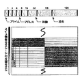
また、情報を与えるための2つの可能性がある。最初の可能性は、(8ビット映像レベル表現の場合には)最小数である8つのサブフィールドSFを使用することであり、これらの8つのSFは、256のレベルを生成することが可能である。そのようなモードは、図1に示されている。
【0013】
各サブフィールドは3つの部分に分割される。アドレス指定部分と、持続部分と、消去部分に分割される。光発生のために作動されるべきプラズマセル(PDPの代表的なセル)に書き込み電圧を印加することによってラインごとにプラズマセルのアドレス指定を行うために、アドレス指定期間が使用される。代表的な持続電圧を用いて持続パルスをすべてのセルに与えることによって、書き込みされたプラズマセルの光発生の期間として、持続期間が使用される。最後に、消去期間が、セル放電を消去するために使用され、これによって、セルを中立状態にする(neutralizing)。
【0014】
図2は、図1の8ビット符号に基づいて256の映像レベルのすべてを生成するために使用される標準的な方法を表わしている。
【0015】
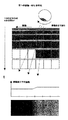
図3によると、観察者の目は画像期間の持続期間にわたって、光発生の様々な組み合わせを積分・総和し、これによって、グレイレベル・階調における様々な色合い・暗度(shades)を再生成する。移動がない場合(図3の左側)、積分軸は、パネルに垂直な時間軸の方向である。観察者は、同じピクセルから来る情報を積分し、乱れを探知しないであろう。もし対象が動く場合には(図3の右側)、観察者は、この対象をフレームtからt+1まで追跡する(目で追う)。ブラウン管では、放射時間が非常に短いので、たとえ大きな動きでも対象を正確に目で追うことができるであろう。PDPでは、放射時間が全体の画像期間にわたって伸びている。フレームごとに3つのピクセル分対象が移動することによって、3つの異なるピクセルから来るサブフィールドを積分する。不運にも、これら3つのピクセルの間に、次第な移り変わりが無い場合には、この積分は、図3の右側の下に示されているように誤りコンターの結果に至る。
【0016】
上で述べた第2の可能性は、単に限られた数のレベルを表現するが、時間的な乱れを決して導かないようにこれらのレベルを選択することである。この符号は、“増加的な符号”と呼ばれる。なぜならば、どのレベルに関してもレベルB>レベルAである場合には、符号B=符号A+C(Cは正の値)となるからである。この符号化は、明らかに、生成可能な映像レベルの数をアドレス指定期間の数に制限する。しかしながら、そのような符号によって、2つの連続するオンのサブフィールドの間には、決してオフのサブフィールドが存在しない。いくつかの最適化されたディザリング技術やエラー拡散技術(error diffusion technique)が、この正確さの欠如を補うことが可能である。
【0017】
そのような符号化方法の主な利点は、誤りコンター効果を抑制することである。なぜならば、2つの同様なレベル(例えば、127/128)の間に不連続さが存在しないからである。その理由で、このモードは、時々、誤りコンターの無い(No False Contour)のためにNFCモードと呼ばれる。一方、そのようなモードは、十分な映像レベルを処理するためにディザリングを要求するため、ディザリングノイズを引き起こし得る。
【0018】
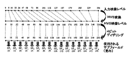
図4は、16のサブフィールドと4ビットディザリングに基づく増加的符号を用いた256レベルの生成を示している。これに関して、16の利用可能な基本レベルの空間−時間の非相関関係(spatio−temporal uncorrelation)が用いられる。16のサブフィールドに基づくこの例は、説明を簡単にするために以下で用いられる。
【0019】
図5は、移動がある場合に、このモードによって表現される移り変わり127/128の場合を示している。図5は、同様なレベルの間での移動がある移り変わりは、もはや誤りコンターの源ではなく、スムーズな移り変わりの結果となる。図4は、アドレス指定期間のない増加的なアドレス指定モードを示している。グローバルプライミング(global priming)とよばれる全体的なアドレス指定動作が、フレーム期間の始めに実行される。この動作の後に、光を発生しないセルの放電だけが消される選択的消去動作が実行される。他のすべてのセルは、次の持続期間の間、放電状態にされたままである。選択的な消去動作は各サブフィールドの部分である。フレーム期間の最後に全体的な消去動作が、すべてのセルを中立状態にする。図6は、4ビットディザリングを用いて増加的符号化方式を実施する可能性を示している。
【0020】
さらなる重要な態様は、ガンマ訂正の実行である。ブラウン管ディスプレイは、ビーム強度に対して線形的な応答を持たず、むしろ2次的な応答(quadratic response)を持つ。図7は、この原理を示している。線形応答の特徴を持つプラズマディスプレイの場合には、ソースレベル(sourcelevel)で予めなされた訂正は、図8に示されるように観察される画像の質を低下させ、画像を不自然にする。この問題を抑制するために、プラズマディスプレイ装置の特定の映像処理部でなされる人工的なガンマ動作は、ソースレベルで予めなされた訂正に対し逆処理・反転処理(invert)を行う。通常、ガンマ訂正は、サブフィールドレベルへの符号化の直前にプラズマディスレイ部でなされる。このガンマ訂正動作は、出力される映像データが図9に示されるように8ビットの解像度に制限されるならば、低映像レベルの破壊につながる。
【0021】
増加的な符号の場合には、そのような効果を回避する機会がある。実際、サブフィールドの重み(weight)でガンマ関数を実施することが可能である。16(4ビット)のディザリング段階を用いて0から255までのガンマ関数(γ=1.82)に従った16のサブフィールドを処理することを仮定する。その場合には、16の可能な映像値Vnの各々に関して、表示される値は、次の進行・数列・プログレッションを守らなければならない。
【0022】
【数3】
【0023】
【数4】
【0024】
特別なことを実行しないならば、16のサブフィールドの各々を16の映像レベルのグループを表現するのに用いてよい。図11は、この原理を示している。図11は、様々な映像レベルが増加的符号の例においてどのように表現されるかを示している。0から15の間のすべてのレベルは、サブフィールドSF0(0)とSF1(2)に基づいてディザリングを適用することによって表現される。224と240の間のすべてのレベルは、サブフィールド:
【数5】
【0025】
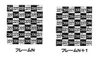
この表現において、ブラックレベルは、SF0として定義される。もちろん、サブフィールド構成において、余分なSF0は存在しない。ブラックレベルは、すべての他のサブフィールドSF1からSF16までを作動させない、または、非作動状態にすることによって、単純に生成可能である。例えば、入力映像レベル12は、ガンマ化(255・(12/255)1,82=1)の後、振幅1をもっているべきであり、これは、図12で示されたディザリングによって表現可能である。均質のブロックにおいてピクセルの半分は、光生成のために作動させられない、半分は、重み2を持つサブフィールドSF1だけを用いて光生成のために作動させられる。フレームからフレームへと、図12に示されるようにディザリングパラーンが作成される。図12は、重みを計算するのに使用される1.82のガンマを考慮して、映像レベル12を表現するために用いられる可能なディザリングを表わしている。
【0026】
他方、もし特別な適合が適用されない場合には、図13に示されるように、映像レベル231(ガンマ化の後は213.5)を表現するために、全く同じディザリングが用いられてよい。図13は、重み(255・(231/255)1.82=213.5)を計算するのに使用される1.82のガンマを考慮して映像レベル231を表現するために用いられる可能なディザリングを表わしている。
【0027】
図12と13は、低レベルと高レベルの両方の範囲に関して、同じ種類のディザリング(4ビット)が使用された場合を示している。16の可能な映像レベルの各々は、均等に256の映像レベルの間に分配され、同じ種類のディザリングが、16のレベルの間に使用され他のレベルを表現する。他方、これは、人間による輝度の認識に適合しない。確かに、人間の目は、明るい範囲(luminous area)におけるよりも、低レベルにおけるノイズにずっと敏感である。
【0028】
上記を考慮して、本発明の目的は、ディザリングの視認度の減少を可能にするディスプレイ装置と方法を提供することである。
【0029】
【課題を解決するための手段】
本発明の1つの態様によると、本発明の目的は、映像画像のピクセルに対応する複数に発光要素を持つ表示装置上での表示のための映像画像データを処理する方法によって解決される。この方法において、各ピクセルのサブフィールドコードワードと、映像画像データのディザリング処理と、ディザリング処理された映像画像データを表示のために行われるサブフィールド符号化と、ディザリング処理の前に行われる網膜関数に従った映像画像データの変換とによって各ピクセルの輝度が制御される。サブフィールドコードワードは、発光要素をオン状態またはオフ状態にするための多数のインパルスに対応する。
【0030】
また、本発明の目的は、映像画像のピルセルに対応する複数の発光要素を持つ表示装置上での表示のための映像顔図データを処理する装置によって解決される。この装置は、輝度制御手段を有する。この輝度制御手段によって少なくとも1つのサブフィールドコードワードを用いて各ピクセルの輝度が制御される。少なくとも1つのサブフィールドコードワードを用いて、映像フレームにおけるサブフィールドに対応する小さいパルスで、光を発生させるために発光要素が作動状態または非作動状態にさせられる。この装置は、映像画像データのディザリング処理を行うディザリング手段と、ディザリング処理が行われた映像画像データに表示のためにサブフィールド符号化処理を行うサブフィールド符号化手段とをさらに有する。この装置は、ディザリング処理の前に網膜関数に従って映像画像を変換する変換手段を有する。
さらなる有益な態様は特許請求の範囲の従属請求項から理解されるであろう。
【0031】
本発明の利点は、サブフィールド構成を変化させることと、人間の視覚組織輝度感度(ウェバーフェヒナーの法則)に基づく適切な変換関数を通しての入力得映像値の変換とによってディザリングの視認度を減らすことである。
【0032】
【発明の実施の形態】
以下において、好適実施形態と共に、本発明をより詳細に説明する。
【0033】
本発明のよりよい理解のために、人間の視覚の生理的な効果を説明する。
【0034】
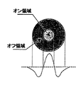
網膜の分析は、視覚組織細胞の基本的な機能の1つを示す。即ちレセプター領域の概念を示す。レセプター領域は、神経単位・ニューロンに関連し、および、輝度刺激に対する反応を決定する小さい網膜領域を表わす。そのようなレセプター領域は、ニューロンの刺激または抑制を可能にし、しばしばオン/オフ領域と呼ばれる領域に分割可能である。図14は、そのようなレセプター領域を表わしている。これらのレセプター領域は、脳へ、各光受容器に位置する輝度の絶対値ではなく、網膜上の2つの隣接点の間で測られた相対値を伝える。このことは、人間の目は、絶対値ではなく局部的なコントラストに敏感であることを意味している。この現象は、図15に示されている。図15で、各領域の真ん中において、グレイのディスクが同じレベルを持っているが、人間の目は、これらを異なって認識する。
【0035】
この現象は、ウェバーフェヒナーの法則と呼ばれ、
【数6】
【数7】
【0036】
この曲線は、人間の目が、最も高い映像レベルよりも低映像レベルに対してすっと敏感であることを示している。それ故に、すべての映像レベルに関して全く同じ種類のディザリングを適用するのは、合理的ではない。もしそのような概念が用いられるならば、最も低い映像レベルに適用されたディザリングによって人間の目が乱される一方、人間の目は、スクリーン上の明るい部分(luminous part)において表現されるすべてのレベルを気にかけないであろう。
【0037】
本明細書で説明される本発明の概念は、人間の目の輝度感度を考慮したものである。その場合には、本発明の目的は、低レベルにはより少なくディザリングを適用し、高レベルにはより多くディザリングを適用することである。さらに、これは、サブフィールド重みの適合・適用と結合される人間の目のモデルを使用することによって、様々なディザリング方式を用いることなく実行される。
【0038】
本発明の概念において定義される最初の段階は、人間の視覚感度HVS(human visual sensitivity)関数に基づく入力画像のフィルタリングに基づく。本発明の説明を簡単にするために、上述したことから得られる1つの関数を用いてよい。明らかに、多くの他の存在するHVS関数が存在するが、本発明はこの1つの特定の関数に限定されない。
【0039】
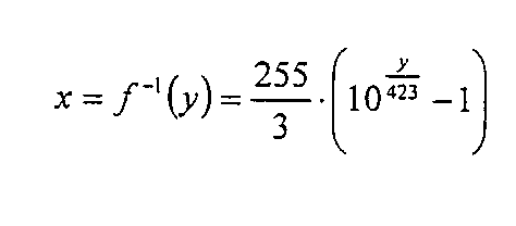
ここでの例では、入力画像が8ビット(Imax=255)で計算された場合、この関数は、
【数8】
【0040】
図16で表現されている使用される変換関数は、LUT(ルックアップテーブル)によって適用されてよく、またはプラズマ専用ICにおける関数によって直接的に適用されてよい。LUTは、最も単純な方法であり、ICにおける限られた資源を必要とする。
【0041】
本発明の概念の次の段階は、サブフィールドを用いた画像符号化の適合された変更である。明らかに、網膜の性質に対応した複雑な変換が、入力画像に適用されてきたが、(同じ網膜の反応は2回とはない(not twice the same retinal behavior))人間の目に対して性格な画像を与えるために、サブフィールド重みにおいて逆変換が適用されるべきである。
【0042】
上で既に述べたように、増加的符号の例が、説明を簡単にするために、再び使用されるが、他のどのような符号化でも本発明に使用可能である。
【0043】
重みにおいて逆変換を適用するために、この逆変換が計算されるべきである。
網膜変換を、
【数9】
【数10】
【0044】
増加的符号に関して新たなサブフィールド重みを計算するために、逆網膜関数が使用される。上で説明した重みの計算において、
【数11】
【0045】
それ故に、これらの段階は、
【数12】
【数13】
【数14】
【数15】
【0046】
増加的符号の場合、B>Aである各値に関して、符号B=符号A+C(ここでCは正である)である。その場合には、数式Vn+1=Vn+SFn+1(n>0)が守られなければならないので、重みが簡単に計算される。これは、サブフィールド重みSFn=Vn−Vn−1:
【数16】
【0047】
新たな重みは、ガンマ関数だけでなく、入力映像値に適用された網膜関数の逆関数も含む・考慮する(include)。
【0048】
この原理に基づいて、上で説明したものと全く同じ実施原理であるが、図18で新たに示される実施原理を用いることが可能である。HVS関数は、ディザリング実行の前に、入力映像レベルに最初に適用される。ディザリングはHVSが適用された入力画像に対して実行される。逆HVS関数は、サブフィールド重みにおいて実施されて、人間の目に対して要求されるガンマ関数を含めて・考慮して正確な画像を与える。しかしながら、ディザリング機能・関数は、HVS関数とHVS関数の逆関数の間で実行されたので、ディザリングレベルは、望まれるようなHVSの性質に従う。それ故に、ディザリングノイズは、すべての表現されるレベルに関して、人間の目では、同じ振幅を持ち、乱れをより小さくする。
【0049】
全体的な概念のさらなる図が、図19に示されている。図19は、HVS概念の実施の結果を表わしている。低映像レベルにおいて、ディザリング段階の前に、伸張・拡張が行われている。低映像レベルは拡張された映像レベル範囲にわたって分配されている。これは、ディザリングレベルの減少の効果を持つ。一方、高映像レベルにおいては、ディザリング段階の前に圧縮が行われている。高映像レベルは、減少させられた映像レベル範囲に集中させられている。その場合には、ディザリングレベルは増加させられる。
【0050】
これは、図20と21と共により良く説明することができる。図20と21は、標準的な方法(先行技術)と新たなHVS概念を用いた様々なレベルの表現を比較している。
【0051】
図20は、低映像レベルの表現における先行技術と新たなHVS概念との間の違いを示している。図20と21において、括弧内の値は、ガンマ化の後に表示されるべき値を表わしている。HVS実施において、より多くのサブフィールドが、低レベル再生のために利用可能である。それ故に、ディザリングはより視認されにくくなる。例えば、レベル4(ガンマ化後は、0.5)は、HVS実施の場合には、1と0の組み合わせで表現される。その場合には、ディザリングパターンは、0と2の組み合わせの先行技術の方法よりも、視認されにくくなっている。
【0052】
図21は、高映像レベルの表現における先行技術と新たなHVS概念との違いを示している。より多くのサブフィールドが、低レベルのために使用されるので、先行技術よりも少ないサブフィールドが高レベルにおいて利用可能である。例えば、レベル216(ガンマ化後は、187.5)は、先行技術では、175と200の組み合わせで表現されているのに対し、HVS概念では165と206の組み合わせで表現されている。しかしながら、人間の目は、高レベルの違いには、敏感さが小さくなるので、画像は、実際には、高レベル範囲においては、質低下とはならない。言い換えると、全体的にディザリングの視認度を減らすために、HVS概念は、低レベルのためのより多くのサブフィールドと、高レベルのためのより少ないサブフィールドとの間の妥協をなす。
【0053】
図22は、本発明の可能な回路実施を表わしている。RGB入力画像は、ディガンマ(degamma)機能ブロック10に転送される。ディガンマ関数ブロック10は、ルックアップテーブルLUT、または、数学的な関数を用いたソフトウェアによって実現可能である。ブロック10の出力は、HVSフィルタリングブロック11に転送される。HVSフィルタリングブロック11は、複合数学的数式(complex mathmatical formula)、または、LUTを単純に用いて網膜の性質を実施する。このブロック11の機能は、プラズマ制御ブロック16が生成したHVS制御信号によって作動状態または非作動状態にさせられることが可能である。その後、ディザリングがディザリングブロック12において加えられる。ディザリングブロック12には、DITH信号が、プラズマ制御ブロック16から与えられる。
【0054】
同じブロック・ディザリングブロック12が、HVS逆重みづけ(HVS inverse weighting)を考慮して、また、考慮しないで、サブフィールド符号化ブロック13を構成してもよい。
【0055】
プラズマディスプレイパネルのアドレス指定に関して、サブフィールドコードワードが、サブフィールド符号化ブロック13から読み出され、ライン方向のPDPアドレス指定のために使用可能な単一の非常に長いコードワードを作成するのに、1つのラインに関するすべてのコードワードが集められる。これは、直列から並列への変換部14(serial to parallel conversion unit)において実行される。プラズマ制御ブロック16は、PDP制御のためにすべてのスキャンパルスとすべての持続パルスを生成する。プラズマ制御部16は、基準タイミングのために、水平同期パルスと垂直同期パルスを受信する。
【0056】
本発明は、人間の視覚組織輝度感度(ウェバーフェヒナーの法則)に基づく適切な変換曲線を通して、映像の変更と共に、サブフィールド構成の共通の変化によってディザリング視認度の減少を可能にする。
【0057】
上述した好適実施形態において、ディザリングはピクセルに基づいてなされる。カラーPDPにおいて、各ピクセルに関して、3つのプラズマセルが存在する。本発明は、ピクセルに基づくディザリングに限定されない。WO−A−01/71702に説明されているようなセルに基づくディザリングが、本発明と結合されて使用されることが可能である。
【0058】
本発明は、特にPDPにおいて適用可能である。プラズマディスプレイは、現在、例えば、TVセットや、コンピュータのモニターのような消費者電子機器に使用されている。しかしながら、本発明の適用は、光放射がサブフィールドにおいて小さなパルスで制御される、即ち、PWM原理が光放射に使用されるマトリックスディスプレイにも適切に可能である。特に、本発明は、DMD(digital micro mirror devices)に適用可能である。
【図面の簡単な説明】
【図1】8のサブフィールド標準符号化の原理を示している。
【図2】標準的なアプローチを使用して256の映像レベルの符号化を示している。
【図3】標準的な符号化の場合での誤りコンター効果を示している。
【図4】増加的符号化を用いての256の映像レベルの生成を示している。
【図5】増加的コードの場合の移動がある移り変わりを示している。
【図6】増加的符号化の実施のための主な処理段階を示している。
【図7】標準的なCRTディスプレイのためのガンマを予め訂正する原理を示している。
【図8】PDP上で標準的な予め訂正された画像の表示の効果を示している。
【図9】入力映像レベルへガンマ関数を適用することによって破壊される低映像レベルを示している。
【図10】増加的符号化において積分されたガンマ進行を示している。
【図11】増加的符号化に用いられるサブフィールド構成を示している。
【図12】ディザリングを用いた映像レベル12の表現を示している。
【図13】ディザリングを用いた映像レベル231の表現を示している。
【図14】網膜のレセプター領域を示している。
【図15】人間の目のコントラスト感度を説明するための図である。
【図16】HVS変換曲線の例を示している。
【図17】積分ガンマ進行を持つHVSに適合させられた増加的符号化方式を示してしる。
【図18】HVSに適合させられた増加的符号化方式の実施の主な処理段階を示している。
【図19】HVS符号化概念と入力映像レベルへのその効果を示している。
【図20】いくつかの低映像レベルに関する標準的な表現とHVS表現との比較を示している。
【図21】いくつかの高映像レベルに関する標準的な表現とHVS表現との比較を示している。
【図22】HVS符号化の回路実施を示している。
【符号の説明】
10 ディガンマ機能ブロック
11 HVSフィルタリングブロック
12 ディザリングブロック
13 サブフィールド符号化ブロック
14 直列から並列への変換ブロック
15 プラズマディスプレイパネル
16 プラズマ制御ブロック[0001]
BACKGROUND OF THE INVENTION
The present invention relates to an apparatus and method for processing a video image for display on a display device having a plurality of light emitting elements corresponding to pixels of the video image. Dithering processing is performed on the video image data, subfield coding processing is performed on the dithered video image for display, and the luminance of each pixel is controlled using the subfield codeword. The subfield codeword corresponds to a number of impulses for turning the light emitting element on and off.
[0002]
[Prior art]
Plasma technology enables the achievement of large size flat color panels (within the limits of cathode ray tubes) with very limited thickness and without any viewing angle limitations. Referring to recent TV in Europe, a lot of work and efforts have been made to improve the quality of TV images. As a result, new technologies such as plasma technology must provide the same or better image quality than standard TV technology. In order to display a video image with a quality similar to that of a cathode ray tube, video data of at least 8 bits is required. In practice, for a gammaization process aimed at reproducing the nonlinear nature of a cathode ray tube into a linear panel such as a plasma panel, a correct interpretation of the low video level is achieved. It is preferable to use more bits than bits.
[0003]
[Patent Document 1]
WO-A-01 / 71702
[Non-Patent Document 1]
“Fundamental of digital image” (Prentice Hall 1989)
[Problems to be solved by the invention]
A plasma display panel (PDP) uses a matrix array of discharge cells that can simply be turned on and off. Unlike CRTs and liquid crystal displays where gray levels and gray levels are expressed by analog control of light emission, plasma display panels control gray levels by modulating the number of small light pulses per frame. This time modulation is integrated by the observer eye over a period corresponding to the time response of the observer eye. Today, there are many techniques to reproduce different video levels using optical pulse modulation (PWM (Pulse Width Modulation)) for each frame.In some cases, timing issues, Sufficient video levels cannot be reproduced due to specific solutions to false contour effects etc. In these cases, in order to artificially represent all the required levels, A dithering technique should be used for display, and the visibility of noise for display is directly linked to the way the base level is selected.
[0004]
Dithering itself is a well-known technique used to reduce the effects of quantization noise due to the reduced number of resolution bits displayed. Dithering adds an artificial level between the existing video levels corresponding to the reduced number of resolution bits displayed. This improves gray scale and gradation, but gives high-frequency, low-amplitude dithering noise that can be recognized by a human viewer only at a small viewing distance.
[0005]
The optimization of the concept and method of dithering is to reduce the visibility of dithering noise, as disclosed in WO-A-01 / 71702.
[0006]
Various reasons result in the lack of video levels for gray levels that are represented on a plasma screen (or similar display) based on light radiation such as a PWM (pulse width modulation) system.
[0007]
Some of the main causes of the lack of level expression are described below.
[0008]
In the case of simple binary coding (each subfield corresponds to 1 bit), 8 subfields are required for an acceptable grayscale representation. Nevertheless, for some single scan panels, the addressing speed is 20 frames for a certain time frame (50 Hz video source (PAL, secum), 60 Hz video source (NTSC). ) For 16.6 milliseconds, and for a 75 Hz video source, 13.3 milliseconds))) is not sufficient to represent 8 subfields.
For good response fidelity, a specific subfield needs to be configured with a specific subfield weight sequence. For example, the subfield sequence increasing smaller than the Fibonacci sequence (1-1-2-3-5-8-13-21-34-55-89-144-233...) Increase. In that case, at least 12 subfields are required to achieve more levels than 255 separate levels corresponding to 8-bit video. Even in the case of a dual scan panel, in particular, the addressing speed is so slow that good encoding and sufficient duration to give good contrast and good peak white improvement cannot be obtained.
[0009]
A new coding concept called incremental code has been developed to completely suppress the PWM related artifacts known as the false contour effect. It was done. Such an encoding system only allows any subfield to be switched off between the two subfields switched on. In that case, the number of video levels that can be expressed is equal to the number of subfields. Since it would not be possible to process 255 separate subfields on a plasma display in about 122 milliseconds required for addressing only, it would not be possible to process sufficient video levels in such a way.
[0010]
For ease of explanation, the last case case is used as an example for further explanation. However, the invention described herein is not limited to this concept.
[0011]
The plasma cell simply has two different states. That is, the plasma cell is simply turned on and off. Thus, the video level is expressed by time modulation. If the number of video levels to be generated is N, the most effective addressing scheme is to address N times. For 8-bit video values, each cell should be addressable 256 times in one video frame. However, this is not technically possible. This is because each addressing operation requires a lot of time (approximately 2 μs per line, ie, 480 μs is required for addressing all lines in the dual scan mode and 256 operations are performed. For the maximum value it requires 256 * 480 μs (this is much more than the 20 ms available time for the 50 Hz display mode).
[0012]
There are also two possibilities for giving information. The first possibility is to use a minimum number of 8 subfields SF (in the case of 8-bit video level representation), and these 8 SFs can generate 256 levels. is there. Such a mode is illustrated in FIG.
[0013]
Each subfield is divided into three parts. Divided into an addressing part, a persistent part and an erasing part. An addressing period is used to address the plasma cell on a line-by-line basis by applying a write voltage to the plasma cell to be activated for light generation (a typical cell of a PDP). By applying a sustain pulse to all cells with a typical sustain voltage, the duration is used as the duration of light generation in the written plasma cell. Finally, the erase period is used to erase the cell discharge, thereby neutralizing the cell.
[0014]
FIG. 2 represents a standard method used to generate all 256 video levels based on the 8-bit code of FIG.
[0015]
According to FIG. 3, the observer's eye integrates and sums various combinations of light generation over the duration of the image period, thereby regenerating various shades and shades in gray levels and tones. To do. When there is no movement (left side of FIG. 3), the integration axis is the direction of the time axis perpendicular to the panel. The observer will not integrate the information coming from the same pixel and detect the disturbance. If the object moves (right side of FIG. 3), the observer tracks (follows) this object from frame t to t + 1. In a cathode ray tube, the radiation time is so short that even a large movement will be able to follow the target accurately. In PDP, the emission time extends over the entire image period. Integrate the subfields coming from three different pixels by moving the object by three pixels per frame. Unfortunately, if there is no gradual transition between these three pixels, this integration results in an error contour as shown at the bottom right of FIG.
[0016]
The second possibility mentioned above is simply to represent a limited number of levels, but to choose these levels so as not to introduce temporal disturbances. This code is called “incremental code”. This is because, for any level, when level B> level A, code B = code A + C (C is a positive value). This encoding obviously limits the number of video levels that can be generated to the number of addressing periods. However, with such a code, there is never an off subfield between two consecutive on subfields. Several optimized dithering techniques and error diffusion techniques can compensate for this lack of accuracy.
[0017]
The main advantage of such an encoding method is to suppress the error contour effect. This is because there is no discontinuity between two similar levels (eg, 127/128). For that reason, this mode is sometimes referred to as NFC mode due to no false contours. On the other hand, such a mode may cause dithering noise because it requires dithering in order to process sufficient video levels.
[0018]
FIG. 4 shows 256 levels of generation using incremental codes based on 16 subfields and 4-bit dithering. In this regard, 16 available base-level space-time uncorrelations are used. This example based on 16 subfields is used below for simplicity of explanation.
[0019]
FIG. 5 shows the case of transition 127/128 represented by this mode when there is movement. FIG. 5 shows that transitions with similar levels of movement are no longer the source of error contours, but result in smooth transitions. FIG. 4 shows an incremental addressing mode with no addressing period. A global addressing operation called global priming is performed at the beginning of the frame period. After this operation, a selective erase operation is performed in which only the discharge of the cells that do not generate light is extinguished. All other cells remain discharged for the next duration. A selective erase operation is part of each subfield. At the end of the frame period, the overall erase operation brings all cells to a neutral state. FIG. 6 illustrates the possibility of implementing an incremental coding scheme using 4-bit dithering.
[0020]
A further important aspect is the execution of gamma correction. A cathode ray tube display does not have a linear response to beam intensity, but rather has a quadratic response. FIG. 7 illustrates this principle. In the case of a plasma display with a linear response characteristic, corrections made in advance at the source level reduce the quality of the observed image as shown in FIG. 8, making the image unnatural. In order to suppress this problem, an artificial gamma operation performed in a specific image processing unit of the plasma display apparatus performs reverse processing / inversion processing (invert) on corrections made in advance at the source level. Normally, gamma correction is performed in the plasma display section immediately before encoding to the subfield level. This gamma correction operation leads to destruction of a low video level if the output video data is limited to 8-bit resolution as shown in FIG.
[0021]
In the case of incremental codes, there is an opportunity to avoid such effects. In fact, it is possible to implement a gamma function with subfield weights. Assume that 16 subfields are processed according to a gamma function from 0 to 255 (γ = 1.82) using 16 (4 bit) dithering stages. In that case, for each of the 16 possible video values Vn, the displayed value must adhere to the next progression, sequence, and progression.
[0022]
[Equation 3]
[0023]
[Expression 4]
[0024]
If nothing special is performed, each of the 16 subfields may be used to represent a group of 16 video levels. FIG. 11 illustrates this principle. FIG. 11 shows how the various video levels are represented in the incremental code example. All levels between 0 and 15 are subfield SF 0 (0) and SF 1 Expressed by applying dithering based on (2). All levels between 224 and 240 are subfields:
[Equation 5]
[0025]
In this expression, the black level is SF 0 Is defined as Of course, in the subfield configuration, the extra SF 0 Does not exist. Black level is all other subfields SF 1 To SF 16 It can be generated simply by not operating or turning it off. For example, the
[0026]
On the other hand, if no special adaptation is applied, exactly the same dithering may be used to represent the video level 231 (213.5 after gamma), as shown in FIG. FIG. 13 shows the weight (255 · (231/255) 1.82 = 213.5) represents the possible dithering used to represent the video level 231 taking into account the gamma of 1.82 used to calculate.
[0027]
FIGS. 12 and 13 show the same type of dithering (4 bits) used for both low and high level ranges. Each of the 16 possible video levels is evenly distributed among the 256 video levels, and the same kind of dithering is used during the 16 levels to represent the other levels. On the other hand, this is not compatible with human perception of luminance. Indeed, the human eye is much more sensitive to noise at low levels than in the bright area.
[0028]
In view of the above, it is an object of the present invention to provide a display device and method that allows dithering visibility to be reduced.
[0029]
[Means for Solving the Problems]
According to one aspect of the present invention, the object of the present invention is solved by a method for processing video image data for display on a display device having a plurality of light emitting elements corresponding to pixels of the video image. In this method, a subfield codeword of each pixel, video image data dithering processing, subfield encoding performed for displaying the dithered video image data, and dithering processing are performed before the dithering processing. The luminance of each pixel is controlled by converting the video image data according to the retina function. The subfield codeword corresponds to a number of impulses for turning the light emitting element on or off.
[0030]
Further, the object of the present invention is solved by an apparatus for processing video face map data for display on a display device having a plurality of light emitting elements corresponding to pill cells of a video image. This apparatus has luminance control means. The luminance control means controls the luminance of each pixel using at least one subfield codeword. Using at least one subfield codeword, the light emitting element is activated or deactivated to generate light with small pulses corresponding to the subfields in the video frame. The apparatus further includes dithering means for performing dithering processing of video image data, and subfield encoding means for performing subfield encoding processing for display on the video image data subjected to the dithering processing. This apparatus has conversion means for converting a video image according to a retinal function before the dithering process.
Further advantageous embodiments will be understood from the dependent claims.
[0031]
An advantage of the present invention is that it reduces the visibility of dithering by changing the subfield configuration and converting the input video value through an appropriate conversion function based on human visual tissue luminance sensitivity (Webber-Fechner's law). That is.
[0032]
DETAILED DESCRIPTION OF THE INVENTION
In the following, the present invention will be described in more detail with preferred embodiments.
[0033]
For a better understanding of the present invention, the physiological effects of human vision will be described.
[0034]
Analysis of the retina shows one of the basic functions of visual tissue cells. That is, the concept of the receptor region is shown. The receptor region represents a small retinal region that is associated with neuronal units and neurons and determines the response to luminance stimuli. Such receptor regions allow stimulation or inhibition of neurons and can be divided into regions often referred to as on / off regions. FIG. 14 represents such a receptor region. These receptor regions convey to the brain the relative value measured between two adjacent points on the retina, not the absolute value of the brightness located at each photoreceptor. This means that the human eye is sensitive to local contrast, not absolute values. This phenomenon is illustrated in FIG. In FIG. 15, in the middle of each area, the gray disk has the same level, but the human eye perceives them differently.
[0035]
This phenomenon is called Weber Fechner's Law,
[Formula 6]
[Expression 7]
[0036]
This curve shows that the human eye is much more sensitive to low video levels than to the highest video level. It is therefore not reasonable to apply exactly the same kind of dithering for all video levels. If such a concept is used, the human eye is disturbed by dithering applied to the lowest video level, while the human eye is all represented in the luminous part of the screen Will not care about the level.
[0037]
The inventive concept described herein takes into account the luminance sensitivity of the human eye. In that case, the object of the present invention is to apply less dithering to low levels and more dithering to high levels. Furthermore, this is done without using various dithering schemes by using a human eye model combined with adaptation and application of subfield weights.
[0038]
The first step defined in the concept of the present invention is based on the filtering of the input image based on the human visual sensitivity HVS (Human Visual Sensitivity) function. To simplify the description of the present invention, a single function resulting from the above may be used. Obviously, there are many other existing HVS functions, but the invention is not limited to this one specific function.
[0039]
In this example, if the input image is calculated with 8 bits (Imax = 255), this function is
[Equation 8]
[0040]
The conversion function used represented in FIG. 16 may be applied by a LUT (Look Up Table) or directly by a function in a plasma only IC. LUT is the simplest method and requires limited resources in the IC.
[0041]
The next stage of the inventive concept is an adapted modification of image coding using subfields. Obviously, complex transformations corresponding to the nature of the retina have been applied to the input image, but not the same retinal response (not twice the same retinal behavior) to the human eye. In order to give a smooth image, an inverse transform should be applied in the subfield weights.
[0042]
As already mentioned above, the incremental code example is used again for ease of explanation, but any other encoding can be used in the present invention.
[0043]
In order to apply the inverse transform on the weights, this inverse transform should be calculated.
Retina transformation,
[Equation 9]
[Expression 10]
[0044]
The inverse retinal function is used to calculate new subfield weights for incremental codes. In the weight calculation described above,
## EQU11 ##
[0045]
Therefore, these stages are
[Expression 12]
[Formula 13]
[Expression 14]
[Expression 15]
[0046]
For incremental signs, for each value where B> A, sign B = sign A + C (where C is positive). In that case, the formula V n + 1 = V n + SF n + 1 Since (n> 0) must be observed, the weight is easily calculated. This is the subfield weight SF n = V n -V n-1 :
[Expression 16]
[0047]
The new weights include not only the gamma function but also the inverse function of the retinal function applied to the input video value.
[0048]
Based on this principle, the implementation principle is exactly the same as described above, but the implementation principle newly shown in FIG. 18 can be used. The HVS function is first applied to the input video level before performing dithering. Dithering is performed on an input image to which HVS is applied. The inverse HVS function is implemented in subfield weights to give an accurate image, including and taking into account the gamma function required for the human eye. However, since the dithering function / function is executed between the HVS function and the inverse of the HVS function, the dithering level follows the nature of the HVS as desired. Therefore, dithering noise has the same amplitude and less perturbation in the human eye for all expressed levels.
[0049]
A further diagram of the overall concept is shown in FIG. FIG. 19 represents the results of implementation of the HVS concept. At the low video level, expansion / expansion is performed before the dithering stage. The low video level is distributed over the extended video level range. This has the effect of reducing the dithering level. On the other hand, at the high video level, compression is performed before the dithering stage. The high video level is concentrated in the reduced video level range. In that case, the dithering level is increased.
[0050]
This can be better explained in conjunction with FIGS. 20 and 21 compare various levels of representation using the standard method (prior art) and the new HVS concept.
[0051]
FIG. 20 illustrates the difference between the prior art and the new HVS concept in low video level representation. 20 and 21, the values in parentheses represent the values that should be displayed after gamma conversion. In the HVS implementation, more subfields are available for low level playback. Therefore, dithering is less visible. For example, level 4 (0.5 after gamma conversion) is expressed by a combination of 1 and 0 in the case of HVS implementation. In that case, the dithering pattern is less visible than the prior art method of the combination of 0 and 2.
[0052]
FIG. 21 shows the difference between the prior art and the new HVS concept in high video level representation. Since more subfields are used for lower levels, fewer subfields are available at higher levels than in the prior art. For example, level 216 (187.5 after gamma) is represented by a combination of 175 and 200 in the prior art, whereas it is represented by a combination of 165 and 206 in the HVS concept. However, the human eye is less sensitive to high level differences, so the image is not actually degraded in the high level range. In other words, to reduce dithering visibility overall, the HVS concept makes a compromise between more subfields for the low level and fewer subfields for the high level.
[0053]
FIG. 22 represents a possible circuit implementation of the present invention. The RGB input image is transferred to a
[0054]
The same
[0055]
With respect to plasma display panel addressing, a subfield codeword is read from the
[0056]
The present invention allows dithering visibility to be reduced by common changes in subfield configuration, along with video changes, through an appropriate transformation curve based on human visual tissue luminance sensitivity (Webber-Fechner's Law).
[0057]
In the preferred embodiment described above, dithering is done on a pixel basis. In the color PDP, there are three plasma cells for each pixel. The present invention is not limited to pixel-based dithering. Cell-based dithering as described in WO-A-01 / 71702 can be used in conjunction with the present invention.
[0058]
The present invention is particularly applicable to PDPs. Plasma displays are currently used in consumer electronic devices such as TV sets and computer monitors, for example. However, the application of the invention is also possible suitably for matrix displays in which the light emission is controlled with small pulses in the subfield, ie the PWM principle is used for light emission. In particular, the present invention can be applied to DMD (digital micro mirror devices).
[Brief description of the drawings]
FIG. 1 illustrates the principle of 8 subfield standard encoding.
FIG. 2 illustrates 256 video level encoding using a standard approach.
FIG. 3 shows the error contour effect in the case of standard coding.
FIG. 4 illustrates the generation of 256 video levels using incremental encoding.
FIG. 5 shows a transition with movement for incremental code.
FIG. 6 shows the main processing steps for performing incremental encoding.
FIG. 7 illustrates the principle of pre-correcting gamma for a standard CRT display.
FIG. 8 illustrates the effect of displaying a standard pre-corrected image on a PDP.
FIG. 9 shows the low video level destroyed by applying a gamma function to the input video level.
FIG. 10 shows the integrated gamma progression in incremental encoding.
FIG. 11 shows a subfield configuration used for incremental encoding.
FIG. 12 shows a representation of
FIG. 13 shows a representation of a video level 231 using dithering.
FIG. 14 shows the receptor region of the retina.
FIG. 15 is a diagram for explaining contrast sensitivity of human eyes.
FIG. 16 shows an example of an HVS conversion curve.
FIG. 17 shows an incremental coding scheme adapted to HVS with integral gamma progression.
FIG. 18 shows the main processing steps of the implementation of an incremental coding scheme adapted to HVS.
FIG. 19 shows the HVS coding concept and its effect on the input video level.
FIG. 20 shows a comparison between standard and HVS representations for several low video levels.
FIG. 21 shows a comparison of standard and HVS representations for several high video levels.
FIG. 22 shows a circuit implementation of HVS encoding.
[Explanation of symbols]
10 digamma function block
11 HVS filtering block
12 Dithering block
13 Subfield coding block
14 Conversion block from serial to parallel
15 Plasma display panel
16 Plasma control block
Claims (8)
ピクセルの輝度は、少なくとも1つのサブフィールドコードワードによって制御され、これにより、前記発光要素は、映像フレームにおけるサブフィールドに対応する光出力のため、オンまたはオフ状態にされ、
サブフィールドには、サブフィールド重みが割り当てられ、該サブフィールド重みは、
このサブフィールドの間、光出力がオンのとき、ピクセルが光を形成する時間長さを定め、
当該方法は、
前記映像画像データにディザリング処理を行う段階;および
輝度制御のため、前記ディザリング処理された映像画像データに、サブフィールド符号化処理を行う段階;
を有し、さらに、
前記ディザリング処理を行う段階、および前記輝度制御のため、前記ディザリング処理された映像画像データに、サブフィールド符号化処理を行う段階の前に、ウェバーフェヒナーの法則に対応する非線形関数により、前記映像画像データを変換する段階;
を含み、
前記サブフィールド符号化処理を行う段階において、特定のコードが使用され、該コードを用いて、ビット入力に対応づけることにより、フレーム期間中、前記サブフィールドの配置において、オフ状態のサブフィールドが2つのオン状態のサブフィールドの間に、または前に配置されることが回避され、
前記サブフィールド重みの階調は、前記ウェバーフェヒナーの法則に対応する非線形関数の逆関数を、ガンマ関数と組み合わせることにより、人の視覚システムに適合され、前記階調の得られた映像レベルを定め、前記得られた映像レベル間の差異に基づいて、前記サブフィールド重みが計算され、
前記サブフィールド符号化処理を行う段階において、前記ディザリング処理された映像画像データの逆変換は、ガンマ動作と組み合わされることを特徴とする方法。A method of processing video image data for display on a display device having a plurality of light emitting elements corresponding to pixels of the video image,
Intensity of the pixel is controlled by at least one sub-field code word, by which, the light emitting element, for light output corresponding to the sub-fields in a video frame are turned on or off,
Subfields are assigned subfield weights, which are
During this subfield, when the light output is on, it defines the length of time that the pixel forms light ,
The method is
Performing a dithering process on the video image data; and performing a subfield encoding process on the dithered video image data for brightness control;
In addition,
Performing the dithering process and, for the luminance control, before performing the subfield encoding process on the dithered video image data, the nonlinear function corresponding to the Weber-Fechner law Converting video image data;
Including
In the step of performing the subfield encoding process, a specific code is used, and by using the code to correspond to the bit input, 2 subfields in the off state are arranged in the subfield arrangement during the frame period. Is placed between or before two on- state subfields,
The gradation of the subfield weight is adapted to a human visual system by combining an inverse function of a non-linear function corresponding to the Weber-Fechner's law with a gamma function to determine the obtained video level of the gradation. The subfield weights are calculated based on the difference between the obtained video levels;
The method of performing the subfield encoding process, wherein the inverse transformation of the dithered video image data is combined with a gamma operation.
当該装置は、輝度制御手段を有し、これにより、ピクセルの輝度は、少なくとも1つのサブフィールドコードワードによって制御され、これにより、前記発光要素は、映像フレームにおけるサブフィールドに対応する光出力のため、オンまたはオフ状態にされ、
サブフィールドには、サブフィールド重みが割り当てられ、該サブフィールド重みは、このサブフィールドの間、ピクセルがオンにされる時間長さを定め、
当該装置は、
前記映像画像データをディザリング処理するディザリング手段;
ディザリングの前に、ウェバーフェヒナーの法則に対応する非線形関数により、前記ビデオ画像データを変換する変換手段;ならびに
特定のコードを使用して表示するための前記ディザリング処理された映像画像データをサブフィールド符号化するサブフィールド符号化手段であって、これにより、ビット入力に対応づけることにより、フレーム期間中、前記サブフィールドの配置において、オフ状態のサブフィールドが2つのオン状態のサブフィールドの間に、または前に配置されることが回避される、サブフィールド符号化手段;
を有し、
前記ウェバーフェヒナーの法則に対応する非線形関数の逆関数をガンマ関数と組み合わせることにより、前記サブフィールド重みの階調を定める、人の視覚システム適合手段と、
前記階調の得られた映像レベルを定める手段と、
前記得られた映像レベルの間の差異に基づいて、前記サブフィールド重みを計算する手段と、
があり、
前記サブフィールド符号化段階において、前記ディザリング処理された映像画像データの逆変換がガンマ動作と組み合わされることを特徴とする装置。A device for processing video image data for display on a display device having a plurality of light emitting elements corresponding to pixels of the video image,
The device has luminance control means, whereby the luminance of the pixel is controlled by at least one subfield codeword, whereby the light emitting element is for light output corresponding to a subfield in the video frame. It is turned on or off,
Sub Fields subfield weights are assigned, the sub-field weights, during this sub-field defines the length of time the pixel is turned on,
The device is
Dithering means for dithering the video image data;
Conversion means for converting the video image data by a non-linear function corresponding to Weber-Fechner's law prior to dithering; and substituting the dithered video image data for display using a specific code Subfield encoding means for performing field encoding, whereby an off-state subfield is arranged between two on- state subfields in the subfield arrangement during a frame period by associating with a bit input. Subfield encoding means, which is avoided to be placed in front of or in front of ;
Have
A human visual system adaptation means for determining the gradation of the subfield weights by combining an inverse function of a non-linear function corresponding to the Weber-Fechner law with a gamma function;
Means for determining the obtained video level of the gradation;
Means for calculating the subfield weights based on the difference between the obtained video levels;
There is
The apparatus of claim 1, wherein in the subfield encoding step, the inverse transformation of the dithered video image data is combined with a gamma operation.
Applications Claiming Priority (1)
| Application Number | Priority Date | Filing Date | Title |
|---|---|---|---|
| EP02090298A EP1391865A1 (en) | 2002-08-23 | 2002-08-23 | Plasma display panel (PDP) - Reduction of dithering noise while displaying less video levels than required |
Publications (2)
| Publication Number | Publication Date |
|---|---|
| JP2004133400A JP2004133400A (en) | 2004-04-30 |
| JP4659347B2 true JP4659347B2 (en) | 2011-03-30 |
Family
ID=30775859
Family Applications (1)
| Application Number | Title | Priority Date | Filing Date |
|---|---|---|---|
| JP2003208275A Expired - Fee Related JP4659347B2 (en) | 2002-08-23 | 2003-08-21 | Plasma display panel (PDP) that displays less video level than required to improve dithering noise |
Country Status (7)
| Country | Link |
|---|---|
| US (1) | US7522130B2 (en) |
| EP (1) | EP1391865A1 (en) |
| JP (1) | JP4659347B2 (en) |
| KR (1) | KR100955013B1 (en) |
| CN (1) | CN100452138C (en) |
| DE (1) | DE60324070D1 (en) |
| TW (1) | TWI225238B (en) |
Families Citing this family (13)
| Publication number | Priority date | Publication date | Assignee | Title |
|---|---|---|---|---|
| KR100551016B1 (en) * | 2004-05-25 | 2006-02-13 | 삼성에스디아이 주식회사 | Method for displaying gray of plasma display panel and plasma display device |
| EP1622119A1 (en) * | 2004-07-29 | 2006-02-01 | Deutsche Thomson-Brandt Gmbh | Method and apparatus for power level control and/or contrast control of a display device |
| US7746303B2 (en) * | 2005-11-17 | 2010-06-29 | Honeywell International Inc. | Method and apparatus for extending the color depth of displays |
| TWI394121B (en) * | 2006-12-18 | 2013-04-21 | Sony Corp | An image processing apparatus, an image processing method, and a recording medium |
| CN101611424B (en) * | 2007-01-19 | 2013-01-09 | 汤姆森许可贸易公司 | Identifying banding in digital images |
| KR101487548B1 (en) * | 2007-05-18 | 2015-01-29 | 소니 주식회사 | Display device, control method and recording medium for computer program for display device |
| US8988552B2 (en) | 2011-09-26 | 2015-03-24 | Dolby Laboratories Licensing Corporation | Image formats and related methods and apparatuses |
| RU2665211C1 (en) | 2011-12-06 | 2018-08-28 | Долби Лэборетериз Лайсенсинг Корпорейшн | Device and method of improving perceptual luminance nonlinearity-based image data exchange across different display capabilities |
| US10242650B2 (en) | 2011-12-06 | 2019-03-26 | Dolby Laboratories Licensing Corporation | Perceptual luminance nonlinearity-based image data exchange across different display capabilities |
| CN104767566B (en) * | 2014-01-07 | 2018-11-30 | 中兴通讯股份有限公司 | A kind of light-dimming method and device for alleviating interframe flashing |
| CN106027291B (en) * | 2015-11-25 | 2019-03-12 | 北京邮电大学 | BE business QoE evaluation method based on weber Fechner theorem |
| CN108370405B (en) | 2015-12-23 | 2019-11-26 | 华为技术有限公司 | A kind of picture signal conversion process method, device and terminal device |
| JP7065458B2 (en) | 2018-07-13 | 2022-05-12 | パナソニックIpマネジメント株式会社 | Video display device and video display method |
Citations (5)
| Publication number | Priority date | Publication date | Assignee | Title |
|---|---|---|---|---|
| JPH11143420A (en) * | 1997-11-06 | 1999-05-28 | Mitsubishi Electric Corp | Gradation display method and display device |
| JPH11161221A (en) * | 1997-08-29 | 1999-06-18 | Texas Instr Inc <Ti> | Non-binary pulse modulation for improved brightness |
| JP2000259118A (en) * | 1999-03-04 | 2000-09-22 | Pioneer Electronic Corp | Display panel driving method |
| JP2000352954A (en) * | 1999-04-28 | 2000-12-19 | Thomson Multimedia Sa | Method for processing video image in order to display on display device and device therefor |
| JP2002082649A (en) * | 2000-07-07 | 2002-03-22 | Matsushita Electric Ind Co Ltd | Display device and display method |
Family Cites Families (12)
| Publication number | Priority date | Publication date | Assignee | Title |
|---|---|---|---|---|
| US5371515A (en) * | 1989-09-28 | 1994-12-06 | Sun Microsystems, Inc. | Method and apparatus for non-linear dithering of digital images |
| US6614413B2 (en) * | 1998-04-22 | 2003-09-02 | Pioneer Electronic Corporation | Method of driving plasma display panel |
| EP0978817A1 (en) * | 1998-08-07 | 2000-02-09 | Deutsche Thomson-Brandt Gmbh | Method and apparatus for processing video pictures, especially for false contour effect compensation |
| KR100289534B1 (en) * | 1998-09-16 | 2001-05-02 | 김순택 | A method for displaying gray scale of PDP and an apparatus for the same |
| EP1022714A3 (en) * | 1999-01-18 | 2001-05-09 | Pioneer Corporation | Method for driving a plasma display panel |
| KR100473514B1 (en) * | 1999-01-22 | 2005-03-08 | 마츠시타 덴끼 산교 가부시키가이샤 | Apparatus and method for making a gray scale display with subframes |
| KR100302142B1 (en) * | 1999-08-23 | 2001-11-01 | 김춘우 | Fixed Quantity Evaluation Method of Dynamic False Contour Phenomena of Plasma Display |
| EP1136974A1 (en) * | 2000-03-22 | 2001-09-26 | Deutsche Thomson-Brandt Gmbh | Method for processing video data for a display device |
| JP2002006800A (en) * | 2000-06-21 | 2002-01-11 | Pioneer Electronic Corp | Method for driving plasma display panel |
| EP1326223A1 (en) * | 2000-11-30 | 2003-07-09 | THOMSON multimedia S.A. | Method and apparatus for controlling a display device |
| JP4851663B2 (en) * | 2001-07-19 | 2012-01-11 | パナソニック株式会社 | Display panel brightness control method |
| JP5049445B2 (en) * | 2002-03-15 | 2012-10-17 | 株式会社日立製作所 | Display device and driving method thereof |
-
2002
- 2002-08-23 EP EP02090298A patent/EP1391865A1/en not_active Withdrawn
-
2003
- 2003-08-06 KR KR1020030054298A patent/KR100955013B1/en active IP Right Grant
- 2003-08-11 DE DE60324070T patent/DE60324070D1/en not_active Expired - Lifetime
- 2003-08-21 JP JP2003208275A patent/JP4659347B2/en not_active Expired - Fee Related
- 2003-08-22 TW TW092123087A patent/TWI225238B/en not_active IP Right Cessation
- 2003-08-22 CN CNB031550231A patent/CN100452138C/en not_active Expired - Fee Related
- 2003-08-22 US US10/646,183 patent/US7522130B2/en active Active
Patent Citations (5)
| Publication number | Priority date | Publication date | Assignee | Title |
|---|---|---|---|---|
| JPH11161221A (en) * | 1997-08-29 | 1999-06-18 | Texas Instr Inc <Ti> | Non-binary pulse modulation for improved brightness |
| JPH11143420A (en) * | 1997-11-06 | 1999-05-28 | Mitsubishi Electric Corp | Gradation display method and display device |
| JP2000259118A (en) * | 1999-03-04 | 2000-09-22 | Pioneer Electronic Corp | Display panel driving method |
| JP2000352954A (en) * | 1999-04-28 | 2000-12-19 | Thomson Multimedia Sa | Method for processing video image in order to display on display device and device therefor |
| JP2002082649A (en) * | 2000-07-07 | 2002-03-22 | Matsushita Electric Ind Co Ltd | Display device and display method |
Also Published As
| Publication number | Publication date |
|---|---|
| KR100955013B1 (en) | 2010-04-28 |
| CN100452138C (en) | 2009-01-14 |
| DE60324070D1 (en) | 2008-11-27 |
| EP1391865A1 (en) | 2004-02-25 |
| TWI225238B (en) | 2004-12-11 |
| CN1487487A (en) | 2004-04-07 |
| US7522130B2 (en) | 2009-04-21 |
| JP2004133400A (en) | 2004-04-30 |
| US20040036799A1 (en) | 2004-02-26 |
| TW200405262A (en) | 2004-04-01 |
| KR20040018129A (en) | 2004-03-02 |
Similar Documents
| Publication | Publication Date | Title |
|---|---|---|
| AU785352B2 (en) | Method and apparatus for processing video pictures | |
| US6097368A (en) | Motion pixel distortion reduction for a digital display device using pulse number equalization | |
| KR100898851B1 (en) | Method and apparatus for processing video picture data for display on a display device | |
| JP4659347B2 (en) | Plasma display panel (PDP) that displays less video level than required to improve dithering noise | |
| US7609235B2 (en) | Multiscan display on a plasma display panel | |
| KR101077251B1 (en) | Method for processing video pictures for false contours and dithering noise compensation | |
| EP1262947A1 (en) | Method and apparatus for processing video picture data for a display device | |
| JP3829752B2 (en) | Image display method and image display apparatus | |
| US8576263B2 (en) | Method and apparatus for processing video pictures | |
| EP1391867B1 (en) | Plasma display panel (PDP) - improvement of dithering noise while displaying less video levels than required | |
| KR100416143B1 (en) | Gray Scale Display Method for Plasma Display Panel and Apparatus thereof | |
| KR100888463B1 (en) | Method and device for processing video pictures for display on a display device having a plurality of luminous elements | |
| EP1936590B1 (en) | Method and apparatus for processing video pictures | |
| EP1359564B1 (en) | Multiscan display on a plasma display panel | |
| KR20040011358A (en) | Method and apparatus for grayscale enhancement of a display device | |
| KR20050016947A (en) | Method and apparatus for processing video pictures improving dynamic false contour effect compensation |
Legal Events
| Date | Code | Title | Description |
|---|---|---|---|
| A621 | Written request for application examination |
Free format text: JAPANESE INTERMEDIATE CODE: A621 Effective date: 20060620 |
|
| A977 | Report on retrieval |
Free format text: JAPANESE INTERMEDIATE CODE: A971007 Effective date: 20090518 |
|
| A131 | Notification of reasons for refusal |
Free format text: JAPANESE INTERMEDIATE CODE: A131 Effective date: 20090526 |
|
| A601 | Written request for extension of time |
Free format text: JAPANESE INTERMEDIATE CODE: A601 Effective date: 20090824 |
|
| A602 | Written permission of extension of time |
Free format text: JAPANESE INTERMEDIATE CODE: A602 Effective date: 20090827 |
|
| A521 | Request for written amendment filed |
Free format text: JAPANESE INTERMEDIATE CODE: A523 Effective date: 20091126 |
|
| A131 | Notification of reasons for refusal |
Free format text: JAPANESE INTERMEDIATE CODE: A131 Effective date: 20100309 |
|
| A601 | Written request for extension of time |
Free format text: JAPANESE INTERMEDIATE CODE: A601 Effective date: 20100607 |
|
| A602 | Written permission of extension of time |
Free format text: JAPANESE INTERMEDIATE CODE: A602 Effective date: 20100610 |
|
| A521 | Request for written amendment filed |
Free format text: JAPANESE INTERMEDIATE CODE: A523 Effective date: 20100817 |
|
| TRDD | Decision of grant or rejection written | ||
| A01 | Written decision to grant a patent or to grant a registration (utility model) |
Free format text: JAPANESE INTERMEDIATE CODE: A01 Effective date: 20101207 |
|
| A01 | Written decision to grant a patent or to grant a registration (utility model) |
Free format text: JAPANESE INTERMEDIATE CODE: A01 |
|
| A61 | First payment of annual fees (during grant procedure) |
Free format text: JAPANESE INTERMEDIATE CODE: A61 Effective date: 20101227 |
|
| FPAY | Renewal fee payment (event date is renewal date of database) |
Free format text: PAYMENT UNTIL: 20140107 Year of fee payment: 3 |
|
| R150 | Certificate of patent or registration of utility model |
Ref document number: 4659347 Country of ref document: JP Free format text: JAPANESE INTERMEDIATE CODE: R150 Free format text: JAPANESE INTERMEDIATE CODE: R150 |
|
| R250 | Receipt of annual fees |
Free format text: JAPANESE INTERMEDIATE CODE: R250 |
|
| S111 | Request for change of ownership or part of ownership |
Free format text: JAPANESE INTERMEDIATE CODE: R313113 |
|
| S531 | Written request for registration of change of domicile |
Free format text: JAPANESE INTERMEDIATE CODE: R313531 |
|
| R350 | Written notification of registration of transfer |
Free format text: JAPANESE INTERMEDIATE CODE: R350 |
|
| R250 | Receipt of annual fees |
Free format text: JAPANESE INTERMEDIATE CODE: R250 |
|
| LAPS | Cancellation because of no payment of annual fees |