JP4657452B2 - Apparatus and method for synthesizing pseudo-stereo sound output from monaural input - Google Patents
Apparatus and method for synthesizing pseudo-stereo sound output from monaural input Download PDFInfo
- Publication number
- JP4657452B2 JP4657452B2 JP2000576672A JP2000576672A JP4657452B2 JP 4657452 B2 JP4657452 B2 JP 4657452B2 JP 2000576672 A JP2000576672 A JP 2000576672A JP 2000576672 A JP2000576672 A JP 2000576672A JP 4657452 B2 JP4657452 B2 JP 4657452B2
- Authority
- JP
- Japan
- Prior art keywords
- signal
- filter
- frequency
- input
- filtered
- Prior art date
- Legal status (The legal status is an assumption and is not a legal conclusion. Google has not performed a legal analysis and makes no representation as to the accuracy of the status listed.)
- Expired - Fee Related
Links
Images


Classifications
-
- H—ELECTRICITY
- H04—ELECTRIC COMMUNICATION TECHNIQUE
- H04S—STEREOPHONIC SYSTEMS
- H04S5/00—Pseudo-stereo systems, e.g. in which additional channel signals are derived from monophonic signals by means of phase shifting, time delay or reverberation
Landscapes
- Physics & Mathematics (AREA)
- Engineering & Computer Science (AREA)
- Acoustics & Sound (AREA)
- Signal Processing (AREA)
- Stereophonic System (AREA)
Description
【0001】
【発明の属する技術分野】
本発明は立体音響再生用のシステムに関し、とくに、擬似立体音響出力信号をモノラル入力信号から合成するシステムに関する。
【0002】
【従来の技術】
音のモノラル再生は、単一のチャンネルによる音の再生である。オーケストラのような音源が録音され、モノラルで再生される(すなわち、単一のラウドスピーカによって再生される)と、録音されたものの音色および奥行きの大部分が再生時に失われる。モノラル録音を2個の空間的に分離されたラウドスピーカによって再生したとしても、オーケストラの音は依然として本質的にラウドスピーカ間のどこかにある1点から発せられているように思われる。
【0003】
立体音響再生は、そのオーケストラの音が2個の分離したマイクロホンにより2つの異なった音響チャンネルで録音された場合に行われる。1対のラウドスピーカによる再生時、オーケストラの音はそのラウドスピーカ間の単一の地点から発せられているのではなく、音源がその2個のラウドスピーカの平面にわたって、かつ、この平面の後方に配置されているように感知される。2チャンネル録音は音場の再生を実現し、それによってリスナーが種々の音源(たとえば、個々の楽器)の位置をつき止めることを可能にすると共に、録音室またはコンサートホールの音響上の特性を感じ取ることを可能にする。
【0004】
本当の立体音響の再生は、これを単一のチャンネル再生から区別する2つの異なった特性によって特徴付けられる。第1の特性は幅の感じを生み出す音源の方向的な分離である。第2の特性は奥行感およびそれが生み出す臨場感である。方向的分離感は、オーケストラの中の楽器の位置のような種々の音源の選択的な位置を判断する能力をリスナーに与えるものとして説明される。他方において、臨場感は、再生を行っているラウドスピーカ自身からではなく、そのラウドスピーカの間および通常それらの若干後方から音が生じているように思われる感じである。この臨場感は、大きさの感じ、音響学的特徴、および録音している位置の奥行をリスナーに提供する。幅、奥行および臨場感を説明するために“雰囲気”という用語が使用されている。換言すると、雰囲気という用語は、方向的分離を除いたとき、幅、奥行および臨場感を説明するためにしばしば使用される。
【0005】
2チャンネル立体音響的な音の再生は、方向的な分離および雰囲気の両方の特性を保つ。合成された立体音響的な音再生は、擬似立体音響再生としても知られており、それは一般にステレオ方向性ではなく、本当の2チャンネルステレオの特徴である雰囲気の感じだけを再生しようとする。
【0006】
2チャンネル立体音響的な音響再生システムがテレビジョン画像または動画のような視覚的媒体と組合せて使用された場合、方向的分離と雰囲気の2つの特性がリスナーに聴覚的−視覚的情景の中にいるように感じさせる。雰囲気の感じにより録音スタジオまたは場所の音響的特性が再生され、方向的な感じにより種々の音が視覚的な映像中のそれらの場所から生じたように思われる。さらに、雰囲気は音がラウドスピーカの平面の後方の位置から生じている感じを生むため、ある3次元的効果もまた生成される。
【0007】
【発明が解決しようとする課題】
合成ステレオシステムはまた、周波数スペクトルが2個のラウドスピーカ間で不適切に分割された場合、リスナーを困惑させる分離感を生む可能性も高い。合成ステレオシステムは、再生しているラウドスピーカにおける可聴周波数スペクトルの関数として音響信号の相対的な振幅および、または位相を制御することによりその意図する効果を達成する。当然リスナーは人間の声の音をよく知っているので、多数の楽器または他の背景雑音の中から人間の声を容易に区別することができる。したがって、声が音響ステージを横切って前後に動いているように感じられた場合、それはリスナーを非常に混乱させる可能性が高い。それと対照的に、リスナーが一群の楽器の中から特定の楽器を聞き分けることは一般にでき難い。したがって、一般に1つの特定の楽器からの音が音響ステージを横切って動いているように感じられた場合のほうが、リスナーの困惑は小さい。従来技術のステレオシンセサイザの多くは、時間遅延装置または他の広帯域信号処理装置を使用してモノラル信号を操作し、不自然な雰囲気を人間の声に付加し、その声が音響ステージのあちこちを不自然に動いているような感じを与える方法で擬似立体音響信号を生成する。
【0008】
【課題を解決するための手段】
本発明の実施形態は、モノラル信号を操作して、耳に心地好いように擬似立体音響信号を生成するように設計された音響強化信号処理を使用することによりこれらおよびその他の問題を解決する。信号処理は比較的多くの雰囲気をモノラル信号中の楽器に付加し、比較的少い雰囲気をモノラル信号中の人間の声に付加する。
【0009】
さらに一般的に言えば、本発明の音響強化信号処理は、出力チャンネルが入力チャンネルより多くの雰囲気を有するように、単一の入力チャンネルから多数の出力チャンネルを生成するために使用されることができる。たとえば、入力チャンネルはモノラル入力チャンネルであってもよく、出力は左および右立体音響的ラウドスピーカを駆動するために増幅され使用されてもよい。
【0010】
1実施形態は、入力チャンネルより多い出力チャンネルを提供するシンセサイザである。1実施形態において、シンセサイザは単一の入力信号から2以上の濾波された出力信号を生成する。入力信号は、差動モードの出力信号を生成する立体感フィルタに供給される。入力信号はまた、共通モードの出力信号を生成する等化装置フィルタに供給される。差動モードおよび共通モードの出力信号が結合されて、出力チャンネルが生成される。
【0011】
2チャンネルシンセサイザは、単一のモノラル入力チャンネルから左および右擬似立体音響出力チャンネルを生成する立体音響シンセサイザとして使用されることが望ましい。左出力チャンネルは左チャンネル結合器によって生成され、右出力チャンネルは右チャンネル結合器によって生成される。
【0012】
シンセサイザは、演算増幅器(op−amp)のようなアナログコンポーネントを使用して構成されてもよい。その代りに、シンセサイザは、たとえばマイクロプロセッサまたはデジタル信号プロセッサ(DSP)のようなコンピュータ上のソフトウェアで構成されてもよい。
【0013】
人間の声の中の望ましくない雰囲気を回避し、その一方でもっとランダムに分布する他の音響信号の雰囲気効果を強化するために、出力チャンネルの周波数帯域が人間の声のホルマント周波数を含む人間の声に対応した周波数帯域と実質的に同位相になるように、シンセサイザが出力の位相等化を行う。左右擬似立体音響入力を生成するためにシンセサイザが立体音響シンセサイザとして使用された場合、位相等化は人間の声を音響ステージの中央に位置させ、スピーチ音の再生時の品質を高める。
【0014】
本発明の1実施形態によると、モノラル信号周波数の相対的な振幅および位相と和信号周波数の相対的振幅とを選択的に変化させることによってモノラル入力信号から共通モードおよび差動モード信号を生成し、共通モード信号と差動モード信号とを結合して左および右の擬似立体音響チャンネル信号を生成することにより、広いステレオ音響イメージとリスニングエリアが得られる。
【0015】
共通モード信号を生成するために、モノラル信号の選択された周波数成分がそのモノラル入力信号の他の信号周波数成分に関してブーストされる。さらに、共通モード信号をさらに成形するためにモノラル信号の選択された位相成分がモノラル入力信号の他の位相成分に関してシフトされる。共通モード信号を生成するために選択的なブーストおよび位相シフトを行うことにより、共通モード信号が差動モード信号によって圧倒されないようにする。
【0016】
差動モード信号を生成するために、モノラル信号の選択された周波数成分は、他のモノラル信号周波数成分に関して減衰(強度を減少)される。差動モード信号を生成するために選択的なブーストを行うことによって、広いステレオイメージと広いリスニングエリアが得られる。差動モード信号成分の選択的強化またはブーストは広いステレオイメージを提供し、また、等化装置によって行われる等化により、差動モード信号の無差別的な増加に関連した耳障りな音およびイメージシフトの問題が実質的に減少する。
【0017】
差動モード信号中の選択された成分を選択的に強化またはブーストすることにより、生演奏では聞こえるが録音されたものにおいてマスキングされることの多い雰囲気音響が知覚されるため、ステレオイメージがさらに強化される。たとえば、生の室内音楽演奏を聴いているリスナーには、楽器から直接放出する音とホールおよび他の物体から反射された音と、観客席の取囲まれた性質のために生じた反響音とが聞こえる。生演奏では、雰囲気(たとえば、反射音および反響音)は容易に知覚され、直接音によりマスキングされない。しかしながら、再生された演奏では、雰囲気音は直接音によってマスキングされるため、生演奏と同じレベルで知覚されない。雰囲気音は一般に、差動信号の静かな(quieter) 周波数の中に存在する傾向があり、差動信号の静かな周波数をブーストすることで雰囲気音のマスキングを除去し、それによって生演奏での雰囲気音の知覚をシミュレートする。
【0018】
差動モード信号の選択的な強化はまた、次のような理由により広いリスニングエリアを提供する。差動モード信号の大きい(loud)周波数成分は、人間の声に対応した周波数とリスナーの頭部の周囲の耳から耳までの距離に匹敵する波長を有する周波数とを含む中間範囲の外側にある傾向がある。本発明の1実施形態によって行われる選択的強化の結果、リスナーの位相敏感度が高まった周波数の成分は、不適当にブーストされることはない。したがって、差動信号の無差別の増加(上述の)のために生じた立体音響的イメージシフト問題が実質的に減少し、リスナーは音響ステージ上の人間の声の位置を突き止めることができる。
【0019】
差動モード信号の選択的なブーストの際、強化する量は、混合されている選択的にブーストされる差動信号のレベルによって決定され、提供される雰囲気の量が比較的一貫していて聞き心地の好いものであるように設定される。
【0020】
本発明の実施形態はまた、通常の音響再生システムによるモニフォニックレコード、磁気テープ、ラジオおよびテレビジョン放送、映画のサウンドトラックおよびデジタルディスクの再生に関する。本発明の実施形態は、たとえば録音されたものが通常の音響再生システムで再生され、上述された利点を提供する左および右のステレオ出力信号が生成されることのできるレコード、デジタルディスクまたは磁気テープを含む任意の媒体上への擬似立体響録音にも適用可能である。
【0021】
【発明の実施の形態】
開示された本発明の利点および特徴は、以下の詳細な説明および図面から当業者によって容易に理解されるであろう。
図面において、任意の3桁の数字の第1桁目のものは、その素子が最初に認められる図面の番号を示している。4桁の参照符号が使用される場合、最初の2桁の数字が図面の番号を示す。
I. 概説
上記に要約されているように、本発明の1実施形態は、出力チャンネルがその入力チャンネルより多くの雰囲気を有するように、1つの入力チャンネルから2以上の出力チャンネルを生成するシンセサイザを含んでいる。説明の都合上および簡明化のために、以下の説明において、入力チャンネルはモノラル入力であり、シンセサイザは左擬似ステレオ出力チャンネルと右擬似ステレオ出力チャンネルとを生成すると仮定する。当業者は、その入力がモノラル入力である必要はなく、本発明の実施形態が、複数の出力チャンネルを単一の入力チャンネルから生成することにより録音された音の雰囲気が生成される多数の適用において使用されることができることを容易に理解するであろう。
【0022】
図1は、モノラル録音および再生システムのブロック図であり、音を単一の(モノラル)情報流107 中の情報に変換するために単一のマイクロホン104 が使用される。ここにおいて使用されているように、情報という用語は、たとえば電気信号、電磁信号、磁気ドメイン、光学ピット、インターネットパケット、デジタル値、アナログまたはデジタル録音、コンピュータプログラムまたはディスクファイル中のデータ等を含む任意の形態のデータ表示を含んでいてもよい。マイクロホン104 によって変換された音は、幅と奥行とを有する音響ステージ102 を横切って散在する音源から発生する。マイクロホン104 によって変換された音はまた、音響ステージ102 付近の壁その他の物体(示されていない)から反射されたものや、音響ステージ102 を取囲んでいる部屋(示されていない)の中の反響から発生する。
【0023】
情報流107 中の情報は、録音/送信(送信)ブロック106 に供給される。送信ブロック106 は、情報流107 を再生/受信(受信)ブロック108 に供給する。送信ブロック106 は、情報を記憶または送信するように構成された任意の装置または技術を表し、たとえばラジオまたはテレビジョン送信機、CD録音装置、磁気録音装置、ディスクファイル、インターネット等が含まれる。同様に、受信ブロック108 は送信ブロック106 から情報を受信するように構成された任意の装置または技術を表し、増幅器110 の入力に供給される電気信号に情報流107 を変換する。増幅器110 の出力は、ラウドスピーカ112 に供給される。ラウドスピーカ112 によって再生された音がリスナー116 によって聞かれたとき、リスナー116 はバーチャル音響ステージ114 を知覚する。
【0024】
音響ステージ102 からの音は単一のマイクロホン104 によって変換され、単一のラウドスピーカ112 によって再生されるため、バーチャル音響ステージ114 は実際の音響ステージ102 よりはるかに小さい。リスナー116 は、幅または雰囲気をほとんど持たない小さいバーチャル音響ステージ114 に対応している局所化したサウンドイメージを知覚する。それとは対照的に、マイクロホン104 の近くに位置し、実際の音響ステージ102 上の生演奏によって生成された音が聞こえるならば、実際の音響ステージ102 に対応した非常に大きいサウンドイメージを知覚する。
【0025】
図2は、図1に示されているものに類似しているが、擬似立体音響再生システムを備えているモノラル録音システムのブロック図である。図2では、音を単一の(モノラル)情報流107 の中の情報に変換するために単一のマイクロホン104 が使用されている。図1の場合のように、マイクロホン104 によって変換された音は、幅と奥行とを有する音響ステージ102 を横切って散在する音源、壁その他の物体から反射したもの、および室内の反響から発生する。情報流107 の中の情報は、録音/送信(送信)ブロック106 に供給される。送信ブロック106 は、情報流107 を再生/受信(受信)ブロック108 に供給する。
【0026】
受信ブロック108 は、強化システム202 の第1の入力およびローパスフィルタ203 の入力にモノラル情報220 を供給する。強化システム202 は、左チャンネルの擬似立体音響出力と右チャンネルの擬似立体音響出力とをオーディオ処理ブロック204 に供給する。オーディオ処理ブロック204 は、トーン制御、バランス制御等のオーディオ強化をさらに行ってもよい。オーディオ処理ブロック204 は左増幅器206 に左チャンネル出力を供給し、右増幅器207 に右チャンネル出力を供給する。オーディオ処理ブロック204 は随意なものであり、なくてもよく、その場合には強化システム202 からの左および右チャンネル出力は左および右増幅器206 および207 にそれぞれ直接供給される。左増幅器206 の出力は左スピーカに供給され、増幅器207 の出力は右スピーカに供給される。
【0027】
ローパスフィルタ203 の出力はバス(低音)増幅器208 の入力に供給され、バス増幅器208 の出力はラウドスピーカ212 に供給される。ローパスフィルタ203 、バス増幅器208 およびラウドスピーカ212 は随意なものであり、なくてもよい。ラウドスピーカ210-212 によって再生され音をリスナー116 が聞き、このリスナーはバーチャル音響ステージ214 を知覚する。
【0028】
強化システム202 は、アナログ信号処理、デジタル信号処理またはその組合せを使用して構成されてもよい。強化システム202 はまた、たとえばインテル社製のPentiumプロセッサまたはその後代のもの等のコンピュータプロセッサ上のソフトウェアで構成されてもよい。強化システム202 はまた、デジタル信号プロセッサ(DSP)中のソフトウェアプログラムとして構成されてもよい。
【0029】
ステレオ強化システム202 は、個別の装置として製造および販売されているオーディオプリアンプや、集積された増幅器および受信機中に内蔵されたオーディオプリアンプ中に組込まれて容易に生産されることができる。
【0030】
市販されている標準的なオーディオコンポーネントにより使用するために、ステレオ強化システム202 の1実施形態は、テープモニタループにおいて使用されてもよいし、あるいは利用可能ならばプリアンプの外部プロセッサループにおいて使用されてもよい。このようなループは、トーン制御、バランス制御および音量制御のようなプリアンプ制御の影響を受けない。その代り、ステレオ強化システム202 は、標準的な立体音響再生システムのプリアンプと電力増幅器との間に配置されてもよい。
【0031】
よく知られているように、立体音響再生システムは、サウンドイメージの生成を試みるものであり、再生音が音響ステージ214 を横切る異なった位置から生じているように知覚されるので、生の音響ステージ102 の経験がシミュレートされる。ステレオサウンドイメージは、聴覚的錯覚のために一般に左および右のラウドスピーカ210 および211 の間に存在するものとして知覚され、ステレオイメージの幅は、左および右ラウドスピーカ210 および211 にそれぞれ供給された情報が類似しているか、あるいは異なっているかに大きく依存する。各ラウドスピーカに供給される情報が同じ(たとえば、モノラル)である場合、サウンドイメージは主としてラウドスピーカ間の“中央ステージ”で生成される。反対に、各ラウドスピーカに供給される情報が異なる場合、サウンドイメージは2個のラウドスピーカの間において広がる。
【0032】
ステレオサウンドイメージの幅は、ラウドスピーカに供給される情報だけでなく、リスナーの位置にも依存する。リスナーは、ラウドスピーカから等距離のところに位置するのが理想である。多くのラウドスピーカシステムに関して、リスナーが1つのラウドスピーカに接近するにつれて、遠いほうのラウドスピーカの音がステレオイメージに与える影響は小さくなり、より近いほうのラウドスピーカだけから音が生じているように知覚される。これは、各ラウドスピーカ中の情報が類似している場合、とくにそうである。したがって、強化システムは、異なった左および右チャンネル出力を供給する。
【0033】
強化システム202 は、モノラル信号220 だけを増幅器206 および207 に直接供給することにより得られる場合よりも多くの雰囲気を有する左および右出力擬似立体出力信号にモノラル入力信号220 を変換する。従来技術において、雰囲気をモノラル信号に付加しようとする種々の試みが行われているが、その結果はまちまちである。それとは対照的に、音強化システム202 が差信号(L−R)に類似している差動モード信号を生成することは有効である。差動モード信号の部分は、強度減少(減衰)されるこの差動モード信号の別の部分に関して強化(ブースト)される。
【0034】
図3は、モノラル入力信号M220 に雰囲気を付加するために左オールパスフィルタ302 および右オールパスフィルタ304 を使用する強化システム202 の1実施形態を示している。左オールパスフィルタ302 および右オールパスフィルタ304 に信号Mが供給される。左オールパスフィルタ302 は、+45°の進相シフトを生成する進相フィルタである。右オールパスフィルタ304 は、−45°の遅相シフトを生成する遅相フィルタである。
【0035】
フィルタ302 の出力は、加算器320 の第1の入力と結合器322 の非反転(加算)入力とに供給される。フィルタ304 の出力は、加算器320 の第2の入力と結合器322 の反転(減算)入力とに供給される。加算器320 の出力は加算器328 の第1の入力に供給される。結合器322 の出力は結合器326 の非反転入力に供給される。
【0036】
フィルタ304 の出力はまた、立体感フィルタ324 の入力に供給される。この立体感フィルタ324 の出力は結合器326 の反転入力と加算器328 の第2の入力に供給される。フィルタ302 の出力はまた、加算器328 の第3の入力と結合器326 の非反転入力とに供給される。
【0037】
加算器328 の出力は、ハイパスフィルタ308 と加算器306 の第1の入力とに供給される。結合器326 の出力は、ハイパスフィルタ310 と加算器306 の第2の入力とに供給される。加算器306 の出力は、ローパスフィルタ309 に供給される。
ハイパスフィルタ308 の出力は加算器312 の第1の入力に供給され、ローパスフィルタ309 の出力は加算器312 の第2の入力に供給される。加算器312 の出力は左チャンネル出力増幅器316 の入力に供給され、増幅器316 の出力は、左チャンネル出力に供給される。
【0038】
ハイパスフィルタ310 の出力は加算器314 の第1の入力に供給され、ローパスフィルタ309 の出力は加算器314 の第2の入力に供給される。加算器314 の出力は右チャンネル出力増幅器318 の入力に供給され、増幅器318 の出力は右チャンネル出力に供給される。
【0039】
強化システム300 は、オーディオスペクトル全体にわたって位相シフトを導入するためにオールパスフィルタ302 、304 を使用することにより左および右擬似立体音響出力を生成する。加算器306 により供給された左プラス右(L+R)信号の低周波数部分は、加算器312 および314 のそれぞれによって左および右チャンネルと混合される。ローパスフィルタ309 のロールオフ周波数より上の周波数において、L+R信号は左および右チャンネルに対してほとんど付加されない。したがって、ローパスフィルタ309 のロールオフ周波数より上の周波数では、左および右チャンネルは本質的に直交している(すなわち、ほぼ90°離れている)。ローパスフィルタ309 のロールオフ周波数より下の低周波数では、若干のL+R信号が左および右チャンネルに付加される。したがって、ローパスフィルタ309 のカットオフ周波数からそれ程除去されない低周波数では、左および右チャンネルが離れている角度は90°より小さい。非常に低い周波数では、ハイパスフィルタ308 および310 は、左および右出力信号がローパスフィルタ309 の出力で供給される(L+R)信号から優先的に生じるように、左および右チャンネル信号の大部分を減衰する。したがって、非常に低い周波数において、左および右出力信号は実質的に同位相である。
【0040】
図3に示されている強化システム300 は、モノラル入力信号の擬似立体音響強化を行い、人間の声に対応した周波数範囲内の非常に多くの雰囲気を生成するが、人間の声の周波数帯域より上のまたは下の周波数範囲内の雰囲気はほとんど生成しないことが可能である。
【0041】
差信号を無差別に増加することにより、人間の声を含む中間範囲の周波数に差信号の強い周波数成分が集中される傾向があるために、問題が生じる可能性が高い。従来技術の1つの問題は、再生音が非常に耳ざわりでうるさいことである。これは、聴覚が中間範囲内の約700Hz乃至約7kHz(キロヘルツ)の範囲の周波数に対して非常に敏感なためである。これらの周波数では、リスナーの頭部の位置のわずかな変化がステレオイメージをうるさいものに変えてしまう。
【0042】
図4は、人間の声に対応した周波数範囲の雰囲気が比較的少く生成され、その他の周波数範囲の雰囲気が比較的多く生成される音強化システム400 のブロック図である。この音強化システム400 において、モノラル入力信号M220 はバッファ増幅器402 を通って立体感フィルタ404 の入力に供給される。立体感フィルタ404 の出力は、第1の出力チャンネル(L−R)と、利得1を有する反転増幅器406 の入力とに供給される。増幅器406 は180°の位相シフトを生じさせる。増幅器406 の出力は第2の出力チャンネル(R−L)に供給される。
【0043】
立体感フィルタ404 は、人間の声(中間帯域)に対応した周波数範囲内のモノラル信号220 の周波数成分を強度減少(減衰)する。したがって、中間帯域に対応した周波数範囲において、第1および第2の出力チャンネルが減衰される。しかしながら、中間帯域において出力の位相は依然180°ずれており、強化システムの周波数応答特性は均一(平坦)ではない。もっと良好な強化システムならば、出力の周波数応答特性がさらに良好に均一になり、中間帯域でほぼ同位相となる出力が供給される。
【0044】
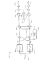
図5は、さらに均一な周波数応答特性と、中間帯域の周波数にわたってほぼ同位相の出力とを実現する音強化システム500 のブロック図である。このシステム500 は、2つの擬似立体音響出力チャンネルを単一のモノラル入力チャンネルから生成するために立体感フィルタ504 および等化装置506 を使用する。システム500 において、モノラル入力M220 はバッファ増幅器502 の入力に供給される。増幅器502 の出力は立体感フィルタ504 の入力とバンドパスフィルタ508 の入力に供給される。立体感フィルタ504 の出力は加算器512 の第1の入力と反転増幅器514 の入力とに供給される。反転増幅器514 の出力は加算器516 の第1の入力に供給される。
【0045】
バンドパスフィルタ508 の出力は90°位相シフタ510 の入力に供給される。位相シフタ510 の出力は加算器512 の第2の入力と加算器516 の第2の入力とに供給される。加算器512 の出力は左チャンネル出力222 であり、加算器516 の出力は右チャンネル出力224 である。
【0046】
立体感フィルタ504 の出力は、差動モード信号である。1実施形態において、差動モード信号は、聴力が非常に敏感な周波数(約400Hz乃至約10kHz、好ましくは約700Hz乃至約7kHz)が不適切にブーストされず、リスナーの両耳間の距離に匹敵する波長を有する差信号成分が不適切にブーストされないようなものである。
【0047】
立体感フィルタ504 によって供給される差動モード信号は、いくつかの点で擬似差信号(L−R)である。立体感フィルタ504 は差動モード信号を周波数の関数として選択的に減衰する。立体感フィルタ伝達関数の1実施形態の一例は図7に示されている。示されているように、差動モード信号はとくに、約400Hz乃至約10kHz、とくに約700Hz乃至約7kHzの中間帯域周波数範囲で減衰される。人間の聴力は中間帯域の周波数に対して非常に敏感である。これは、主にこのような周波数範囲には、リスナーの両耳間の距離に匹敵する波長を有する差信号成分が含まれているためである。中間帯域の周波数範囲における減衰は約2乃至15dBであることが好ましい。
【0048】
従来技術に関連して上述したように、このような周波数内の大きい音の差信号はうるさい耳ざわりな音になり、リスナーの位置をラウドスピーカ間において等距離な場所に制限する。このような周波数を減衰することによって、実質的に耳ざわりな音が減少すると共に、位置に対する制限が緩和される。中間帯域減衰はまた、主として、中間帯域領域の音に対する人間の聴力の感度を高めることに貢献する。人間の外耳部分は、リスナーの正面に位置する音源から発せられた中間帯域の音の減衰を生じさせる。内耳管の中における共鳴は中間帯域領域内の音に対する感度を増加させ、それによって内耳は外耳を補償する。内耳と外耳との相互作用は、主に頭部関連伝達関数(HRTF)の物理的な特徴を表している。立体感フィルタの中間帯域減衰は、それが内耳と外耳の相互作用を補償するという点でHRTFと同じ効果が得られる。
【0049】
バンドパスフィルタ508 と位相シフタ510 とを含んでいる等化装置フィルタ506 は、差動モード信号を補足するために共通モード信号を供給する。図8には、バンドパスフィルタ508 の1実施形態に対する適切な等化特性が示されている。この実施形態において、バンドパスフィルタ508 はほぼ700Hzおよび7kHzで−3dBの周波数を有し、10進ごとにほぼ20dBロールオフする。バンドパスフィルタの6.3kHzの帯域幅は、人間の声の動作範囲に近いものである。別の実施形態では、低いほうの−3dBの周波数が400Hz乃至2000Hzの範囲内であってよく、高いほうの−3dB周波数が3000Hz乃至10kHzの範囲内であってよい。
【0050】
位相シフタ510 は、バンドパスフィルタ508 の出力をフィルタ504 の出力に関してほぼ90°シフトする。90°のシフトは、フィルタ504 の0°の位相出力と反転増幅器514 の180°の位相出力との間のほぼ中央に共通モード信号を位置させる。したがって、共通モード信号は立体感フィルタ504 の出力における差動モード信号と増幅器514 の出力における反転された差動モード信号の両者から位相的にほぼ等距離となる。換言すると、共通モード信号の位相は、反転されたおよび通常の差動モード信号に関してほぼバランスが取れている。
【0051】
立体感フィルタのフィルタ伝達特性はまた、過度に強調された低音を回避するために1以上のオクターブごとに約6dBの割合(示されていない)で約300Hzより低い周波数でロールオフするように設計されていることが望ましい。このような低い周波数のロールオフは、図2に示されている低音スピーカ212 が含まれている場合、とくに望ましい。
【0052】
立体感フィルタにより生成された差動モード信号は主として、擬似立体音響出力中の雰囲気に影響する。したがって、中間帯域の周波数範囲内の差動モード信号の成分は、中間帯域の周波数外の周波数範囲内の成分に関して減衰される。これには、中間帯域の周波数内の雰囲気が少く生成され、それ以外の周波数範囲の雰囲気が多く生成されるという効果がある。中間帯域の差動モード信号成分は、中間帯域の両側の差動モード信号成分に関して約8dB減衰されることが好ましい。等化装置フィルタによって生成される共通モード信号は、雰囲気をほとんどまたは全く提供しない。したがって、差動モードおよび共通モード信号が結合されたとき、結果的に得られた信号が中間帯域の外側の周波数範囲内に多く雰囲気を有しているように、中間帯域の周波数範囲内の共通モード信号の成分が他の周波数範囲に関してブーストされる。
【0053】
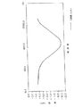
図9は、図5に示された音響強調システムの左および右チャンネル出力のxyグラフである。図9に示されているグラフは、x軸上に周波数を示し、y軸上に振幅(dB)を示している。1実施形態において、左および右チャンネルは1100Hz付近のクロスオーバ周波数において実質的に同位相であり、振幅が実質的に等しい。このクロスオーバ周波数は、バンドパスフィルタ508 の中心周波数および立体感フィルタ504 の中心周波数にほぼ対応している。別の実施形態において、クロスオーバ周波数は約500Hzから約9kHzの範囲に入っている。さらに別の実施形態において、左および右チャンネルはクロスオーバー周波数において実質的に同位相ではない。その左および右チャンネルは非常に高い周波数(たとえば、10kHzを越える周波数)および非常に低い周波数(たとえば、300Hzより下の周波数)で実質的に180°位相がずれており、振幅が等しい。
【0054】
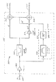
II. 5キャパシタ擬似ステレオシンセサイザ
強調システム500 は、アナログ信号処理、デジタル信号処理またはその組合せを使用して構成されることができる。図6には、強調システム500 の1実施形態が示されている。この実施形態は少数のフィルタキャパシタを使用し、集積回路用として適合できるようにされている。図6において、モノラル入力220 は抵抗602 の第1の端子に供給される。抵抗602 の第2の端子は、一方の端子が接地された抵抗603 の接地されていない端子およびバッファ増幅器608 の非反転入力に接続されている。バッファ増幅器608 の反転入力は、一方の端子が接地された抵抗604 の接地されていない端子およびフィードバック抵抗609 の第1の端子に接続されている。増幅器608 の出力はフィードバック抵抗609 の第2の端子に供給される。
【0055】
増幅器608 の出力はまた、立体感フィルタ504 の入力に供給される。立体感フィルタ504 の入力は、抵抗610 の第1の端子と、キャパシタ612 の第1の端子と、抵抗614 の第1の端子とに供給される。キャパシタ612 の第2の端子は、一方の端子が接地されている抵抗613 の接地されていない端子と抵抗611 の第1の端子とに供給される。抵抗614 の第2の端子は、一方の端子が接地されているキャパシタ616 の接地されていない端子と抵抗615 の第1の端子とに接続されている。抵抗615 の第2の端子と、抵抗611 の第2の端子と、および抵抗610 の第2の端子とは全て、立体感フィルタ504 の出力に接続されている。
【0056】
立体感フィルタ504 の出力は、抵抗617 の第1の端子(反転増幅器514 の入力)に供給される。抵抗617 の第2の端子は、フィードバック抵抗619 の第1の端子と、演算増幅器618 の反転入力とに接続されている。演算増幅器618 の非反転入力は接地端子に接続され、演算増幅器618 の出力はフィードバック抵抗619 の第2の端子に供給される。
【0057】
反転増幅器ブロック514 の出力である演算増幅器618 の出力はまた、抵抗625 の第1の端子を含む加算器516 の入力に供給される。抵抗625 の第2の端子は抵抗626 の第2の端子と、フィードバック抵抗627 の第1の端子と、演算増幅器628 の反転入力とに接続されている。演算増幅器628 の出力は、フィードバック抵抗627 の第2の端子と、右チャンネル出力224 とに供給される。
【0058】
演算増幅器618 の出力はまた、抵抗620 の第1の端子を含む加算器512 の入力に供給される。抵抗620 の第2の端子は、抵抗621 の第2の端子と、フィードバック抵抗622 の第1の端子と、演算増幅器624 の反転入力とに接続されている。演算増幅器624 の出力は、フィードバック抵抗622 の第2の端子と、左チャンネル出力222 とに供給される。
【0059】
増幅器608 の出力はまた、キャパシタ635 の第1の端子を含むバンドパスフィルタ508 の第1の端子に供給される。キャパシタ635 の第2の端子は、一方の端子が接地されている抵抗634 の接地されていない端子と、抵抗636 の第1の端子とに接続されている。抵抗636 の第2の端子は、一方の端子が接地されているキャパシタ637 の接地されていない端子と演算増幅器638 の非反転入力とに接続されている。演算増幅器638 の出力は、演算増幅器638 の反転入力に供給される。演算増幅器638 の出力はまた、バンドパスフィルタ508 の出力として抵抗639 の第1の端子および抵抗640 の第1の端子に供給される。抵抗640 の第2の端子は、一方の端子が接地されているキャパシタ641 の接地されていない端子と演算増幅器642 の非反転入力とに接続されている。抵抗639 の第2の端子は、フィードバック抵抗643 の第1の端子と演算増幅器642 の反転入力とに接続されている。演算増幅器642 の出力は、フィードバック抵抗643 の第2の端子と、抵抗644 の第1の端子とに供給される。抵抗644 の第2の端子は、一方の端子が接地されている抵抗648 の接地されていない端子に接続されている。位相シフタ510 の出力端子である抵抗644 の第2の端子はまた、抵抗626 の第1の端子と、抵抗621 の第1の端子とに接続されている。
【0060】
演算増幅器608 ,618 ,638 および642 は、テキサス・インスツルメンツ社製のTL074演算増幅器であることが好ましい。表1には、図5に示されている抵抗(キロオーム)およびキャパシタ(マイクロファラド)の近似的な部品値がリストにされている。
【0061】
【表1】

【0062】
これらの理由から、濾波用として使用される集積回路では、内部キャパシタを使用せず、外部キャパシタに依存する。一般に、各外部キャパシタには、集積回路上に少くとも1つの外部接続部(たとえば、少くとも1つのピン)が必要である。したがって、必要とされるフィルタキャパシタの数は集積回路上の外部接続部の数に影響を与え、したがって集積回路の寸法および費用に影響を与える。図6に示されている回路は少数のキャパシタしか使用しない利点を有している。
【0063】
III . 擬似立体音響の録音
本発明の実施形態は、通常のステレオ音響録音の再生、および通常の音響再生システムにより再生されたときに上述した利点を提供する特有のステレオ音響録音の製造のいずれにも適用できる。したがって、開示されているステレオ強調システム202 によって行われる強調は、録音を強調するために有効的に使用されることができる。このような録音は、ステレオ強調システム202 を備えていないオーディオシステム、あるいはバイパスされているステレオ強調システム202 を備えたオーディオシステムで再生されることができる。
【0064】
ここに説明するステレオ強調システム202 を備えたシステムは、レーザディスク、デジタル・バーサタイル・ディスク(DVD)、レコード、磁気テープ、あるいはビデオテープまたは映画フィルム上の音響チャンネルのようなデジタル録音に応答する通常の立体音響再生装置を含んでいる。この再生装置は、左および右チャンネルステレオ信号L,Rを増幅器に供給し、この増幅器から左および右信号がラウドスピーカに供給される。
【0065】
類似した装置は、それ自身がレコードの物理的な溝、磁気テープ等の磁性体の磁気ドメイン、または光学手段によって読出されることのできるデジタル情報の形態でデータを保持する録音を行う際に使用される。このようなデータは、通常の音響再生システムで再生されたときに上述した利点を全て実現する信号成分から形成された左および右ステレオ信号を規定する。したがって、本発明の原理を使用する音響録音を形成する録音システムは、モノラル入力信号をマイクロホン104 から、あるいはモノラル入力信号M220 を供給するように構成されたシステム108 のような通常のモノラル再生システムから受信する。再生システム108 は、レーザディスク、レコード、磁気テープ、あるいはビデオまたはフィルムサウンドトラック媒体のようなデジタル録音を含む任意の通常の録音媒体からその出力信号を供給してもよい。
【0066】
図2の強調システム202 が雰囲気の強調を与える録音を行うために使用された場合、このような録音が通常のステレオ再生装置と共同して、雰囲気を知覚させる強調信号を含む成分を有する左および右擬似立体音響出力信号が生成される。ここに説明した装置および方法によって行われた録音は、特有の信号発生データがその録音の中に埋込まれているために他の立体音響録音とは区別される。通常の録音再生媒体によるこのような特有の録音が再生されるとき、特定された信号成分を含む上述した利点を有する擬似立体音響が生成される。
【0067】
IV. その他の実施形態
上記には、録音された演奏の結果得られた雰囲気および立体音響イメージを通常の録音の再生および改善された録音の生成において実質的に改善するシステムが開示されている。このようなシステムは標準的なオーディオ装置により容易に使用され、既存のオーディオ装置に容易に付加される。さらに、開示されたシステムは、プリアンプおよび、または集積された増幅器中に容易に内蔵されることができる。このような内蔵には、開示したシステムをバイパスするための構造が含まれる。
【0068】
開示されたステレオ強調システムは、アナログ技術、デジタル技術または両者の組合せを使用して容易に構成される。さらに、開示されたステレオ強化システムは集積回路技術により容易に構成される。
【0069】
開示されたシステムはまた、エアラインエンターテイメントシステム、劇場の音響システム、イメージ強調や立体感補正を含む録音を生成するための録音システム、ならびにオルガンまたはシンセサイザのような電子楽器を含む種々のオーディオシステムにより使用されてもよいし、あるいはそのようなオーディオシステム中に内蔵されてもよい。
【0070】
さらに、開示されたシステムはとくに、自動車の音響システムおよびボートのような他のビークルの音響システムにおいて有効である。
【0071】
以上、本発明の特定の実施形態を説明および図示してきたが、当業者は添付された請求の範囲によって制限される本発明の技術的範囲を逸脱することなく種々の修正および変更を行うことが可能である。
【0072】
【図面の簡単な説明】
【図1】 モノラル録音および再生システムのブロック図。
【図2】 擬似立体音響再生システムを備えたモノラル録音システムのブロック図。
【図3】 2つの擬似立体音響出力チャンネルを単一のモノラル入力チャンネルから生成するためにオールパスフィルタを使用する音強化システムの1実施形態のブロック図。
【図4】 2つの擬似立体音響出力チャンネルを単一のモノラル入力チャンネルから生成するために立体感フィルタを使用する音強化システムの1実施形態のブロック図。
【図5】 2つの擬似立体音響出力チャンネルを単一のモノラル入力チャンネルから生成するために立体感フィルタおよび等化装置を使用する音強化システムの1実施形態のブロック図。
【図6】 図5に示された音強化システムの1実施形態の概略回路図
【図7】 立体感フィルタの伝達関数の1実施形態のグラフ。
【図8】 図7に示されている立体感フィルタの伝達関数と共に使用されるバンドパスフィルタの伝達関数の1実施形態のグラフ。
【図9】 擬似ステレオ音強化システムの左および右チャンネル出力の1実施形態のグラフ。[0001]
BACKGROUND OF THE INVENTION
The present invention relates to a system for reproducing stereophonic sound, and more particularly to a system for synthesizing a pseudostereoscopic output signal from a monaural input signal.
[0002]
[Prior art]
The monaural reproduction of sound is reproduction of sound by a single channel. When a sound source such as an orchestra is recorded and played in mono (ie, played by a single loudspeaker), most of the recorded timbre and depth is lost during playback. Even if the monaural recording is played by two spatially separated loudspeakers, the orchestra sounds still appear to originate from a single point somewhere between the loudspeakers.
[0003]
Stereophonic reproduction is performed when the orchestra sound is recorded on two different acoustic channels by two separate microphones. When playing with a pair of loudspeakers, the orchestra sound is not emitted from a single point between the loudspeakers, but the sound source spans the planes of the two loudspeakers and behind this plane. Perceived as being placed. Two-channel recording provides sound field reproduction, which allows listeners to locate various sound sources (eg, individual instruments) and senses the acoustic characteristics of the recording room or concert hall Make it possible.
[0004]
Real stereophonic reproduction is characterized by two different characteristics that distinguish it from single channel reproduction. The first characteristic is the directional separation of the sound source that creates a feeling of width. The second characteristic is a sense of depth and a sense of reality that it produces. Directional separation is described as providing the listener with the ability to determine the selective position of various sound sources, such as the position of an instrument in an orchestra. On the other hand, the sense of presence is a feeling that sounds seem to be generated between the loudspeakers themselves and usually slightly behind them, not from the loudspeakers performing the playback themselves. This sense of presence provides the listener with a sense of size, acoustic features, and depth of the recording location. The term “atmosphere” is used to describe width, depth, and presence. In other words, the term atmosphere is often used to describe width, depth and presence when excluding directional separation.
[0005]
Two-channel stereophonic sound reproduction preserves both directional separation and atmospheric properties. Synthetic stereophonic sound reproduction is also known as pseudo-stereoscopic sound reproduction, which generally attempts to reproduce only the feeling of atmosphere that is characteristic of true two-channel stereo, not stereo directionality.
[0006]
When a two-channel stereophonic sound reproduction system is used in combination with a visual medium such as a television image or video, the two characteristics of directional separation and atmosphere are in the listener's audio-visual scene. Make you feel like you are. The feeling of atmosphere reproduces the acoustic characteristics of the recording studio or place, and the direction feeling seems to have produced various sounds from those places in the visual image. In addition, because the atmosphere creates the feeling that sound originates from a position behind the loudspeaker plane, certain three-dimensional effects are also created.
[0007]
[Problems to be solved by the invention]
Synthetic stereo systems are also likely to create a sense of separation that confuses the listener if the frequency spectrum is improperly divided between the two loudspeakers. A synthetic stereo system achieves its intended effect by controlling the relative amplitude and / or phase of the acoustic signal as a function of the audible frequency spectrum at the reproducing loudspeaker. Of course, since the listener is well aware of the sound of a human voice, it can be easily distinguished from a number of instruments or other background noise. Thus, if a voice is felt as moving back and forth across the acoustic stage, it is very likely to confuse the listener. In contrast, it is generally difficult for listeners to distinguish a particular instrument from a group of instruments. Therefore, listeners are generally less confused when the sound from one particular instrument is felt to move across the acoustic stage. Many prior art stereo synthesizers use time delay devices or other wideband signal processors to manipulate the monaural signal, adding an unnatural atmosphere to the human voice, which obscures the acoustic stage. A pseudo-stereoscopic sound signal is generated by a method that gives a feeling of moving naturally.
[0008]
[Means for Solving the Problems]
Embodiments of the present invention solve these and other problems by using sound enhanced signal processing designed to manipulate monaural signals to produce pseudostereoscopic sound signals that are comfortable to the ear. Signal processing adds a relatively large atmosphere to the instrument in the monaural signal and adds a relatively small atmosphere to the human voice in the monaural signal.
[0009]
More generally speaking, the sound enhancement signal processing of the present invention can be used to generate multiple output channels from a single input channel, such that the output channel has more atmosphere than the input channel. it can. For example, the input channel may be a mono input channel and the output may be amplified and used to drive left and right stereophonic loudspeakers.
[0010]
One embodiment is a synthesizer that provides more output channels than input channels. In one embodiment, the synthesizer generates two or more filtered output signals from a single input signal. The input signal is supplied to a stereoscopic filter that generates a differential mode output signal. The input signal is also fed to an equalizer filter that produces a common mode output signal. The differential mode and common mode output signals are combined to produce an output channel.
[0011]
The two-channel synthesizer is preferably used as a stereophonic synthesizer that generates left and right pseudostereoscopic output channels from a single mono input channel. The left output channel is generated by the left channel combiner and the right output channel is generated by the right channel combiner.
[0012]
The synthesizer may be configured using analog components such as operational amplifiers (op-amps). Alternatively, the synthesizer may consist of software on a computer such as a microprocessor or digital signal processor (DSP).
[0013]
In order to avoid the undesirable atmosphere in the human voice while enhancing the atmospheric effect of other acoustic signals distributed more randomly, the frequency band of the output channel contains human formant frequencies. The synthesizer performs phase equalization of the output so that it is substantially in phase with the frequency band corresponding to the voice. When a synthesizer is used as a stereophonic synthesizer to generate a left and right pseudostereoscopic input, phase equalization places the human voice in the center of the acoustic stage and enhances the quality of speech sound reproduction.
[0014]
According to one embodiment of the present invention, the common mode and differential mode signals are generated from the monaural input signal by selectively changing the relative amplitude and phase of the monaural signal frequency and the relative amplitude of the sum signal frequency. A wide stereo sound image and a listening area can be obtained by combining the common mode signal and the differential mode signal to generate the left and right pseudo-stereo sound channel signals.
[0015]
To generate the common mode signal, the selected frequency component of the monaural signal is boosted with respect to other signal frequency components of the monaural input signal. Furthermore, the selected phase component of the mono signal is shifted with respect to other phase components of the mono input signal to further shape the common mode signal. By performing selective boosting and phase shifting to generate the common mode signal, the common mode signal is not overwhelmed by the differential mode signal.
[0016]
To generate a differential mode signal, selected frequency components of the monaural signal are attenuated (decrease in strength) with respect to other monaural signal frequency components. By performing a selective boost to generate a differential mode signal, a wide stereo image and a wide listening area are obtained. Selective enhancement or boost of differential mode signal components provides a wide stereo image, and the harsh sound and image shift associated with the indiscriminate increase of the differential mode signal due to equalization performed by the equalizer The problem is substantially reduced.
[0017]
By selectively enhancing or boosting selected components in differential mode signals, the stereo image is further enhanced by perceiving atmospheric sounds that can be heard in live performance but often masked in the recorded recording Is done. For example, listeners listening to live chamber music performances may hear sounds emitted directly from instruments, reflected from halls and other objects, and reverberant sounds created by the enclosed nature of the audience seats. Can be heard. In live performances, the atmosphere (eg, reflections and reverberation) is easily perceived and not masked by direct sound. However, in the played performance, the atmospheric sound is masked by the direct sound and is not perceived at the same level as the live performance. Atmospheric sounds generally tend to be present in the quiet frequency of the differential signal, and boosting the quiet frequency of the differential signal eliminates the masking of the atmospheric sound, thereby producing live performance. Simulate the perception of atmospheric sounds.
[0018]
The selective enhancement of the differential mode signal also provides a wide listening area for the following reasons. The loud frequency component of the differential mode signal is outside the intermediate range that includes a frequency corresponding to the human voice and a frequency with a wavelength comparable to the distance from ear to ear around the listener's head. Tend. As a result of the selective enhancement performed by one embodiment of the present invention, frequency components with increased listener phase sensitivity are not boosted inappropriately. Thus, the stereoacoustic image shift problem caused by the indiscriminate increase in differential signals (described above) is substantially reduced and the listener can locate the human voice on the acoustic stage.
[0019]
During selective boosting of differential mode signals, the amount of enhancement is determined by the level of the differential signal being mixed and selectively boosted, and the amount of atmosphere provided is relatively consistent and heard. It is set to be comfortable.
[0020]
Embodiments of the present invention also relate to playback of monifonic records, magnetic tape, radio and television broadcasts, movie soundtracks and digital discs with conventional sound playback systems. Embodiments of the present invention include records, digital discs or magnetic tapes that can be played back in a normal sound reproduction system, for example, to produce left and right stereo output signals that provide the advantages described above. It can also be applied to pseudo-stereophonic recording on any medium including
[0021]
DETAILED DESCRIPTION OF THE INVENTION
The advantages and features of the disclosed invention will be readily appreciated by those skilled in the art from the following detailed description and drawings.
In the drawings, the first digit of any three-digit number indicates the number of the drawing in which the element is first recognized. If a four digit reference is used, the first two digits indicate the drawing number.
I. Outline
As summarized above, one embodiment of the present invention includes a synthesizer that generates two or more output channels from one input channel such that the output channel has more atmosphere than its input channel. . For convenience of explanation and simplicity, in the following description it is assumed that the input channel is a mono input and that the synthesizer generates a left pseudo stereo output channel and a right pseudo stereo output channel. One skilled in the art does not need that input to be a monaural input, and embodiments of the present invention provide a number of applications in which a recorded sound atmosphere is generated by generating multiple output channels from a single input channel. It will be readily understood that it can be used in
[0022]
FIG. 1 is a block diagram of a monaural recording and playback system in which a
[0023]
Information in the
[0024]
Since the sound from the
[0025]
FIG. 2 is a block diagram of a monaural recording system similar to that shown in FIG. 1, but with a pseudo-stereoscopic sound reproduction system. In FIG. 2, a
[0026]
Receive
[0027]
The output of the low-
[0028]
The
[0029]
The
[0030]
One embodiment of
[0031]
As is well known, a stereophonic sound reproduction system attempts to generate a sound image, and since the reproduced sound is perceived as coming from different locations across the sound stage 214, a
[0032]
The width of the stereo sound image depends not only on the information supplied to the loudspeaker, but also on the position of the listener. Ideally, the listener should be located equidistant from the loudspeaker. For many loudspeaker systems, as the listener approaches one loudspeaker, the effect of the sound of the farther loudspeaker on the stereo image becomes smaller, so that the sound comes from only the closer loudspeaker Perceived. This is especially true if the information in each loudspeaker is similar. Thus, the enhancement system provides different left and right channel outputs.
[0033]
The
[0034]
FIG. 3 illustrates one embodiment of an
[0035]
The output of
[0036]
The output of the
[0037]
The output of adder 328 is supplied to a
The output of the
[0038]
The output of the high pass filter 310 is supplied to the first input of the
[0039]
The
[0040]
The
[0041]
Increasing the difference signal indiscriminately tends to cause a problem because strong frequency components of the difference signal tend to be concentrated at intermediate frequencies including human voice. One problem with the prior art is that the reproduced sound is very loud and annoying. This is because hearing is very sensitive to frequencies in the range of about 700 Hz to about 7 kHz (kilohertz). At these frequencies, slight changes in the position of the listener's head can make the stereo image noisy.
[0042]
FIG. 4 is a block diagram of a
[0043]
The stereoscopic filter 404 reduces (attenuates) the frequency component of the
[0044]
FIG. 5 is a block diagram of a
[0045]
The output of the
[0046]
The output of the
[0047]
The differential mode signal supplied by the
[0048]
As described above in connection with the prior art, such a loud sound difference signal within a frequency can be annoying, limiting the listener's position to a location equidistant between the loudspeakers. By attenuating such frequencies, the substantially unpleasant sound is reduced and the restriction on position is relaxed. Midband attenuation also contributes primarily to increasing the sensitivity of human hearing to sounds in the midband region. The human outer ear part causes attenuation of mid-band sounds emitted from a sound source located in front of the listener. Resonance in the inner ear canal increases sensitivity to sound in the midband region, so that the inner ear compensates for the outer ear. The interaction between the inner ear and the outer ear mainly represents the physical characteristics of the head-related transfer function (HRTF). The mid-band attenuation of the stereoscopic filter has the same effect as HRTF in that it compensates for the interaction between the inner ear and the outer ear.
[0049]
An equalizer filter 506 including a
[0050]
[0051]
The filter transfer characteristics of the stereoscopic filter are also designed to roll off at frequencies below about 300 Hz at a rate of about 6 dB per one or more octaves (not shown) to avoid over-emphasized bass. It is desirable that Such a low frequency roll-off is particularly desirable when the bass speaker 212 shown in FIG. 2 is included.
[0052]
The differential mode signal generated by the stereoscopic filter mainly affects the atmosphere in the pseudo stereoscopic sound output. Thus, the components of the differential mode signal within the mid-band frequency range are attenuated with respect to components within the frequency range outside the mid-band frequency. This has the effect of generating a small amount of atmosphere within the frequency in the intermediate band and generating a large amount of atmosphere in other frequency ranges. The mid-band differential mode signal component is preferably attenuated by about 8 dB with respect to the differential mode signal components on both sides of the mid-band. The common mode signal generated by the equalizer filter provides little or no atmosphere. Therefore, when the differential mode and common mode signals are combined, the resulting signal has a common atmosphere in the frequency range outside the intermediate band, so that the common signal in the intermediate band frequency range is The components of the mode signal are boosted with respect to other frequency ranges.
[0053]
FIG. 9 is an xy graph of the left and right channel outputs of the sound enhancement system shown in FIG. The graph shown in FIG. 9 shows frequency on the x-axis and amplitude (dB) on the y-axis. In one embodiment, the left and right channels are substantially in phase and have substantially the same amplitude at a crossover frequency near 1100 Hz. This crossover frequency substantially corresponds to the center frequency of the
[0054]
II. 5 capacitor pseudo stereo synthesizer
The
[0055]
The output of the amplifier 608 is also supplied to the input of the
[0056]
The output of the
[0057]
The output of
[0058]
The output of
[0059]
The output of amplifier 608 is also fed to a first terminal of a
[0060]
The
[0061]
[Table 1]
[0062]
For these reasons, integrated circuits used for filtering do not use internal capacitors but rely on external capacitors. In general, each external capacitor requires at least one external connection (eg, at least one pin) on the integrated circuit. Thus, the number of filter capacitors required affects the number of external connections on the integrated circuit and thus affects the size and cost of the integrated circuit. The circuit shown in FIG. 6 has the advantage of using only a few capacitors.
[0063]
III. Pseudo-stereo sound recording
Embodiments of the present invention can be applied to both the reproduction of normal stereo sound recordings and the production of specific stereo sound recordings that provide the advantages described above when played by a normal sound reproduction system. Thus, the enhancement performed by the disclosed
[0064]
The system with
[0065]
Similar devices are used to make recordings that hold data in the form of digital information that can be read by physical grooves of records, magnetic domains of magnetic material such as magnetic tape, or optical means Is done. Such data defines left and right stereo signals formed from signal components that realize all of the advantages described above when played back by a normal sound playback system. Accordingly, a recording system that forms an acoustic recording using the principles of the present invention may be from a conventional monaural playback system such as
[0066]
When the
[0067]
IV. Other embodiments
The above discloses a system that substantially improves the atmosphere and stereophonic image resulting from a recorded performance in the playback of a normal recording and the generation of an improved recording. Such a system is easily used by standard audio devices and easily added to existing audio devices. Further, the disclosed system can be easily integrated into a preamplifier and / or an integrated amplifier. Such built-in includes a structure for bypassing the disclosed system.
[0068]
The disclosed stereo enhancement system is easily constructed using analog technology, digital technology, or a combination of both. Furthermore, the disclosed stereo enhancement system is easily constructed with integrated circuit technology.
[0069]
The disclosed system also includes a variety of audio systems including airline entertainment systems, theater sound systems, recording systems for generating recordings including image enhancement and stereo correction, and electronic musical instruments such as organs or synthesizers. It may be used or may be embedded in such an audio system.
[0070]
Furthermore, the disclosed system is particularly useful in automotive acoustic systems and other vehicle acoustic systems such as boats.
[0071]
While specific embodiments of the invention have been described and illustrated, those skilled in the art can make various modifications and changes without departing from the scope of the invention, which is limited by the scope of the appended claims. Is possible.
[0072]
[Brief description of the drawings]
FIG. 1 is a block diagram of a monaural recording and playback system.
FIG. 2 is a block diagram of a monaural recording system provided with a pseudo-stereoscopic sound reproduction system.
FIG. 3 is a block diagram of one embodiment of a sound enhancement system that uses an all-pass filter to generate two pseudo-stereo sound output channels from a single monaural input channel.
FIG. 4 is a block diagram of one embodiment of a sound enhancement system that uses a stereo filter to generate two pseudo-stereo sound output channels from a single monaural input channel.
FIG. 5 is a block diagram of one embodiment of a sound enhancement system that uses a stereo filter and an equalizer to generate two pseudo-stereo sound output channels from a single monaural input channel.
6 is a schematic circuit diagram of an embodiment of the sound enhancement system shown in FIG.
FIG. 7 is a graph of an embodiment of a transfer function of a stereoscopic filter.
8 is a graph of one embodiment of a bandpass filter transfer function used in conjunction with the stereoscopic filter transfer function shown in FIG. 7;
FIG. 9 is a graph of one embodiment of the left and right channel output of the pseudo stereo sound enhancement system.
Claims (16)
入力信号を供給され、入力信号の700Hz乃至7kHzの中間帯域の周波数範囲の周波数成分の強度を減少させた第1の濾波された信号を生成するように構成されている第1のフィルタ手段と、
入力信号を供給され、入力信号の中間帯域の周波数範囲の周波数成分の強度を増加させて第2の濾波された信号を生成し、その濾波された信号を90度位相シフトして位相シフトされた第2の濾波され信号を生成するように構成されている第2のフィルタ手段と、
第1の結合アルゴリズムを使用して前記第1の濾波された信号の少くとも一部分を前記位相シフトされた第2の濾波された信号の少くとも一部分と結合して第1のチャンネル出力信号を生成するように構成された第1の結合器と、
第2の結合アルゴリズムを使用して前記第1の濾波された信号の少くとも一部分を180度位相シフトした信号と前記位相シフトされた第2の濾波された信号の少くとも一部分とを結合して第2のチャンネル出力信号を生成するように構成された第2の結合器とを具備しており、
前記第1のチャンネル出力信号と前記第2のチャンネル出力信号とは約1100Hzのクロスオーバー周波数においては実質上同位相で同振幅であり、
前記第1のチャンネル出力信号と前記第2のチャンネル出力信号とは前記中間帯域の周波数範囲においては低い位相差を有しており、約10kHzよりも高い周波数においては大きい位相差を有しており、約10kHzよりも高い周波数における大きい位相差は約180度である信号プロセッサ。In a signal processor that produces a greater number of output signals than the number of input signals,
First filter means provided with an input signal and configured to generate a first filtered signal having reduced intensity of frequency components in the frequency range of the 700 Hz to 7 kHz intermediate band of the input signal;
An input signal is provided and the second filtered signal is generated by increasing the intensity of the frequency component in the frequency range of the intermediate band of the input signal, and the filtered signal is phase shifted by 90 degrees. Second filter means configured to generate a second filtered signal;
A first combining algorithm is used to combine at least a portion of the first filtered signal with at least a portion of the phase shifted second filtered signal to generate a first channel output signal. A first coupler configured to:
Combining at least a portion of the first filtered signal 180 degrees phase shifted with at least a portion of the phase shifted second filtered signal using a second combining algorithm; A second combiner configured to generate a second channel output signal;
The first channel output signal and the second channel output signal have substantially the same phase and amplitude at a crossover frequency of about 1100 Hz,
The first channel output signal and the second channel output signal have a low phase difference in the frequency range of the intermediate band, and have a large phase difference at a frequency higher than about 10 kHz. A signal processor in which the large phase difference at frequencies higher than about 10 kHz is about 180 degrees.
入力信号の中間帯域の周波数範囲の周波数成分の強度を増加させるように入力信号を第2のフィルタによって濾波して、第2の濾波された信号を生成し、この第2の濾波された信号を90度位相シフトして位相シフトされた第2の濾波され信号を生成し、
前記第1の濾波された信号の少くとも一部分を前記位相シフトされた第2の濾波された信号の少くとも一部分と第1の結合方法によって結合して左出力信号を生成し、
前記第1の濾波された信号の少くとも一部分を180度位相シフトした信号と前記位相シフトされた第2の濾波された信号の少くとも一部分とを第2の結合方法によって結合して右出力信号を生成し、
前記左出力信号と右出力信号とは約1100Hzのクロスオーバー周波数においては実質上同位相で同振幅であり、
前記左出力信号と右出力信号とは前記中間帯域の周波数範囲においては低い位相差を有し、約10kHzよりも高い周波数においては大きい位相差を有し、約10kHzよりも高い周波数における大きい位相差は約180度である、オーディオ信号処理方法。 Filtering the input signal with a first filter to reduce the intensity of frequency components in the frequency range of the 700 Hz to 7 kHz intermediate band of the input signal to produce a first filtered signal;
The input signal is filtered by a second filter so as to increase the intensity of the frequency component in the frequency range of the intermediate band of the input signal to generate a second filtered signal, and the second filtered signal is Producing a second filtered signal phase shifted by 90 degrees,
Combining at least a portion of the first filtered signal with at least a portion of the phase shifted second filtered signal by a first combining method to produce a left output signal;
A right output signal is obtained by combining a signal obtained by phase-shifting at least a portion of the first filtered signal by 180 degrees and at least a portion of the phase-shifted second filtered signal by a second combining method. Produces
The left output signal and the right output signal have substantially the same phase and the same amplitude at a crossover frequency of about 1100 Hz,
The left output signal and the right output signal have a low phase difference in the frequency range of the intermediate band, a large phase difference at a frequency higher than about 10 kHz, and a large phase difference at a frequency higher than about 10 kHz. Is an audio signal processing method that is approximately 180 degrees.
入力信号を供給され、入力信号の700Hz乃至7kHzの中間帯域の周波数範囲の周波数成分の強度を減少させた第1の濾波された信号を生成するように構成されている第1のフィルタ手段と、
入力信号を供給され、入力信号の中間帯域の周波数範囲の周波数成分の強度を増加させて第2の濾波された信号を生成し、その濾波された信号を90度位相シフトして位相シフトされた第2の濾波され信号を生成するように構成されている第2のフィルタ手段と、
前記第1の濾波された信号の少くとも一部分を前記位相シフトされた第2の濾波された信号の少くとも一部分と結合して第1のチャンネル出力信号を生成するように構成された第1の結合手段と、
前記第1の濾波された信号の少くとも一部分を180度位相シフトした信号と前記位相シフトされた第2の濾波された信号の少くとも一部分とを結合して第2のチャンネル出力信号を生成するように構成された第2の結合手段とを具備しており、
前記第1のチャンネル出力信号と前記第2のチャンネル出力信号とは約1100Hzのクロスオーバー周波数においては実質上同位相で同振幅であり、
前記第1のチャンネル出力信号と前記第2のチャンネル出力信号とは前記中間帯域の周波数範囲においては低い位相差を有しており、約10kHzよりも高い周波数においては大きい位相差を有しており、約10kHzよりも高い周波数における大きい位相差は約180度である信号プロセッサ。In a signal processor that produces a greater number of output signals than the number of input signals,
First filter means provided with an input signal and configured to generate a first filtered signal having reduced intensity of frequency components in the frequency range of the 700 Hz to 7 kHz intermediate band of the input signal;
An input signal is provided and the second filtered signal is generated by increasing the intensity of the frequency component in the frequency range of the intermediate band of the input signal, and the filtered signal is phase shifted by 90 degrees. Second filter means configured to generate a second filtered signal;
A first filter configured to combine at least a portion of the first filtered signal with at least a portion of the phase shifted second filtered signal to generate a first channel output signal; A coupling means;
Combining at least a portion of the first filtered signal with a phase shift of 180 degrees and at least a portion of the phase shifted second filtered signal to generate a second channel output signal. A second coupling means configured as follows:
The first channel output signal and the second channel output signal have substantially the same phase and amplitude at a crossover frequency of about 1100 Hz,
The first channel output signal and the second channel output signal have a low phase difference in the frequency range of the intermediate band, and have a large phase difference at a frequency higher than about 10 kHz. A signal processor in which the large phase difference at frequencies higher than about 10 kHz is about 180 degrees.
Applications Claiming Priority (3)
| Application Number | Priority Date | Filing Date | Title |
|---|---|---|---|
| US09/170,363 US6590983B1 (en) | 1998-10-13 | 1998-10-13 | Apparatus and method for synthesizing pseudo-stereophonic outputs from a monophonic input |
| US09/170,363 | 1998-10-13 | ||
| PCT/US1999/023188 WO2000022880A2 (en) | 1998-10-13 | 1999-10-05 | Apparatus and method for synthesizing pseudo-stereophonic outputs from a monophonic input |
Related Child Applications (1)
| Application Number | Title | Priority Date | Filing Date |
|---|---|---|---|
| JP2009005859A Division JP2009141972A (en) | 1998-10-13 | 2009-01-14 | Apparatus and method for synthesizing pseudo-stereophonic outputs from monophonic input |
Publications (3)
| Publication Number | Publication Date |
|---|---|
| JP2002528020A JP2002528020A (en) | 2002-08-27 |
| JP2002528020A5 JP2002528020A5 (en) | 2006-11-24 |
| JP4657452B2 true JP4657452B2 (en) | 2011-03-23 |
Family
ID=22619579
Family Applications (2)
| Application Number | Title | Priority Date | Filing Date |
|---|---|---|---|
| JP2000576672A Expired - Fee Related JP4657452B2 (en) | 1998-10-13 | 1999-10-05 | Apparatus and method for synthesizing pseudo-stereo sound output from monaural input |
| JP2009005859A Pending JP2009141972A (en) | 1998-10-13 | 2009-01-14 | Apparatus and method for synthesizing pseudo-stereophonic outputs from monophonic input |
Family Applications After (1)
| Application Number | Title | Priority Date | Filing Date |
|---|---|---|---|
| JP2009005859A Pending JP2009141972A (en) | 1998-10-13 | 2009-01-14 | Apparatus and method for synthesizing pseudo-stereophonic outputs from monophonic input |
Country Status (6)
| Country | Link |
|---|---|
| US (2) | US6590983B1 (en) |
| JP (2) | JP4657452B2 (en) |
| CN (1) | CN1146299C (en) |
| AU (1) | AU1102500A (en) |
| TW (1) | TW447223B (en) |
| WO (1) | WO2000022880A2 (en) |
Families Citing this family (49)
| Publication number | Priority date | Publication date | Assignee | Title |
|---|---|---|---|---|
| US6905686B1 (en) | 1997-12-02 | 2005-06-14 | Neuralab Limited | Active immunization for treatment of alzheimer's disease |
| US7260231B1 (en) * | 1999-05-26 | 2007-08-21 | Donald Scott Wedge | Multi-channel audio panel |
| WO2001039547A1 (en) | 1999-11-25 | 2001-05-31 | Embracing Sound Experience Ab | A method of processing and reproducing an audio stereo signal, and an audio stereo signal reproduction system |
| US7277767B2 (en) * | 1999-12-10 | 2007-10-02 | Srs Labs, Inc. | System and method for enhanced streaming audio |
| JP4371622B2 (en) * | 2001-03-22 | 2009-11-25 | 新日本無線株式会社 | Pseudo stereo circuit |
| US6804565B2 (en) * | 2001-05-07 | 2004-10-12 | Harman International Industries, Incorporated | Data-driven software architecture for digital sound processing and equalization |
| US7447321B2 (en) | 2001-05-07 | 2008-11-04 | Harman International Industries, Incorporated | Sound processing system for configuration of audio signals in a vehicle |
| US7451006B2 (en) * | 2001-05-07 | 2008-11-11 | Harman International Industries, Incorporated | Sound processing system using distortion limiting techniques |
| SE0202159D0 (en) * | 2001-07-10 | 2002-07-09 | Coding Technologies Sweden Ab | Efficientand scalable parametric stereo coding for low bitrate applications |
| FR2827734A1 (en) * | 2001-07-17 | 2003-01-24 | Koninkl Philips Electronics Nv | RECEIVER, METHOD, PROGRAM AND TRANSPORT SIGNAL FOR ADAPTING THE SOUND VOLUME OF AN ACOUSTIC CALLING SIGNAL |
| JP3874099B2 (en) * | 2002-03-18 | 2007-01-31 | ソニー株式会社 | Audio playback device |
| EP1585947B1 (en) * | 2002-05-03 | 2020-01-01 | Harman International Industries, Incorporated | Sound detection and localization system |
| US7443987B2 (en) * | 2002-05-03 | 2008-10-28 | Harman International Industries, Incorporated | Discrete surround audio system for home and automotive listening |
| SE527062C2 (en) * | 2003-07-21 | 2005-12-13 | Embracing Sound Experience Ab | Stereo sound processing method, device and system |
| JP2005130322A (en) * | 2003-10-27 | 2005-05-19 | Matsushita Electric Ind Co Ltd | Image sensor noise eliminating device |
| US7522733B2 (en) * | 2003-12-12 | 2009-04-21 | Srs Labs, Inc. | Systems and methods of spatial image enhancement of a sound source |
| JP3985234B2 (en) * | 2004-06-29 | 2007-10-03 | ソニー株式会社 | Sound image localization device |
| SE0402652D0 (en) | 2004-11-02 | 2004-11-02 | Coding Tech Ab | Methods for improved performance of prediction based multi-channel reconstruction |
| TW200627999A (en) | 2005-01-05 | 2006-08-01 | Srs Labs Inc | Phase compensation techniques to adjust for speaker deficiencies |
| US7817812B2 (en) * | 2005-05-31 | 2010-10-19 | Polk Audio, Inc. | Compact audio reproduction system with large perceived acoustic size and image |
| KR100619082B1 (en) | 2005-07-20 | 2006-09-05 | 삼성전자주식회사 | Method and apparatus for reproducing wide mono sound |
| CN101263739B (en) | 2005-09-13 | 2012-06-20 | Srs实验室有限公司 | Systems and methods for audio processing |
| JP4539570B2 (en) * | 2006-01-19 | 2010-09-08 | 沖電気工業株式会社 | Voice response system |
| WO2007123788A2 (en) * | 2006-04-03 | 2007-11-01 | Srs Labs, Inc. | Audio signal processing |
| SE530180C2 (en) * | 2006-04-19 | 2008-03-18 | Embracing Sound Experience Ab | Speaker Device |
| US8036902B1 (en) | 2006-06-21 | 2011-10-11 | Tellme Networks, Inc. | Audio human verification |
| US8050434B1 (en) | 2006-12-21 | 2011-11-01 | Srs Labs, Inc. | Multi-channel audio enhancement system |
| KR101460824B1 (en) * | 2007-03-09 | 2014-11-11 | 디티에스 엘엘씨 | Method for generating an audio equalization filter, method and system for processing audio signals |
| KR101298658B1 (en) * | 2007-03-16 | 2013-08-21 | 삼성전자주식회사 | Audio playback device having control function of playback speed and method thereof |
| EP2248352B1 (en) | 2008-02-14 | 2013-01-23 | Dolby Laboratories Licensing Corporation | Stereophonic widening |
| US20100070550A1 (en) * | 2008-09-12 | 2010-03-18 | Cardinal Health 209 Inc. | Method and apparatus of a sensor amplifier configured for use in medical applications |
| TWI475896B (en) * | 2008-09-25 | 2015-03-01 | Dolby Lab Licensing Corp | Binaural filters for monophonic compatibility and loudspeaker compatibility |
| US8000485B2 (en) * | 2009-06-01 | 2011-08-16 | Dts, Inc. | Virtual audio processing for loudspeaker or headphone playback |
| CN102577440B (en) * | 2009-07-22 | 2015-10-21 | 斯托明瑞士有限责任公司 | Improve apparatus and method that are stereo or pseudo-stereophonic audio signals |
| US7880541B1 (en) * | 2009-08-18 | 2011-02-01 | Intersil Americas Inc. | Low noise, low power instrumentation amplifier |
| US8259960B2 (en) * | 2009-09-11 | 2012-09-04 | BSG Laboratory, LLC | Phase layering apparatus and method for a complete audio signal |
| KR101408094B1 (en) * | 2010-02-08 | 2014-06-17 | 한국전자통신연구원 | Subsampling Based Receiver using Frequency Selective Noise Canceller |
| WO2012006770A1 (en) * | 2010-07-12 | 2012-01-19 | Huawei Technologies Co., Ltd. | Audio signal generator |
| CN101894559B (en) * | 2010-08-05 | 2012-06-06 | 展讯通信(上海)有限公司 | Audio processing method and device thereof |
| US8988512B2 (en) | 2011-04-14 | 2015-03-24 | Mediatek Inc. | Method for adjusting playback of multimedia content according to detection result of user status and related apparatus thereof |
| WO2013009949A1 (en) | 2011-07-13 | 2013-01-17 | Dts Llc | Microphone array processing system |
| CN102752703A (en) * | 2012-06-28 | 2012-10-24 | 深圳Tcl新技术有限公司 | Mono-channel input and double-channel output method, device and television |
| US9258664B2 (en) | 2013-05-23 | 2016-02-09 | Comhear, Inc. | Headphone audio enhancement system |
| US9326073B2 (en) * | 2014-04-11 | 2016-04-26 | Qualcomm Incorporated | FM filtering for class-G/H headphones |
| CN104967965B (en) * | 2015-06-29 | 2017-06-30 | 北京芝视界科技有限公司 | A kind of audio play control method and system |
| CN105847454A (en) * | 2016-04-20 | 2016-08-10 | 乐视控股(北京)有限公司 | Signal processing method and device |
| CN109640243A (en) * | 2018-12-06 | 2019-04-16 | 广州番禺巨大汽车音响设备有限公司 | Virtual three-dimensional sound effect processing method and system based on the enhancing of DSP audio |
| CN109922420A (en) * | 2019-04-08 | 2019-06-21 | 北京东奥时代教育科技有限公司 | One kind realizing stereosonic method based on sound channel copy |
| CN115460516A (en) * | 2022-09-05 | 2022-12-09 | 中国第一汽车股份有限公司 | Signal processing method, device, equipment and medium for converting single sound channel into stereo sound |
Family Cites Families (50)
| Publication number | Priority date | Publication date | Assignee | Title |
|---|---|---|---|---|
| US3541266A (en) | 1968-09-30 | 1970-11-17 | Octronix Inc | Bandwidth compressor and expander |
| JPS4959605A (en) * | 1972-10-06 | 1974-06-10 | ||
| US4239939A (en) | 1979-03-09 | 1980-12-16 | Rca Corporation | Stereophonic sound synthesizer |
| JPS5927160B2 (en) * | 1979-06-04 | 1984-07-03 | 日本ビクター株式会社 | Pseudo stereo sound reproduction device |
| JPS56122300A (en) * | 1980-02-29 | 1981-09-25 | Kenkichi Tsukamoto | Method and device for orientating acoustic image of reproduced sound in arbitrary position of space |
| US4308424A (en) | 1980-04-14 | 1981-12-29 | Bice Jr Robert G | Simulated stereo from a monaural source sound reproduction system |
| JPS5738301A (en) * | 1980-08-11 | 1982-03-03 | Seijiro Suda | Generating method for high pressure hydrogen |
| US4394535A (en) | 1981-03-09 | 1983-07-19 | Rca Corporation | Split phase stereophonic sound synthesizer |
| US4479235A (en) | 1981-05-08 | 1984-10-23 | Rca Corporation | Switching arrangement for a stereophonic sound synthesizer |
| US4489432A (en) | 1982-05-28 | 1984-12-18 | Polk Audio, Inc. | Method and apparatus for reproducing sound having a realistic ambient field and acoustic image |
| US4457012A (en) | 1982-06-03 | 1984-06-26 | Carver R W | FM Stereo apparatus and method |
| NL8204980A (en) | 1982-12-24 | 1984-07-16 | Philips Nv | Pseudo-stereo circuit - splits monaural audio signal into two channels by frequency selection by operational amplifiers and filtering |
| DE3331352A1 (en) | 1983-08-31 | 1985-03-14 | Blaupunkt-Werke Gmbh, 3200 Hildesheim | Circuit arrangement and process for optional mono and stereo sound operation of audio and video radio receivers and recorders |
| NL8303945A (en) | 1983-11-17 | 1985-06-17 | Philips Nv | DEVICE FOR REALIZING A PSEUDO STEREO SIGNAL. |
| US4496979A (en) | 1983-11-22 | 1985-01-29 | Casat Technology, Inc. | FM High-fidelity processor |
| GB2157475A (en) | 1984-04-12 | 1985-10-23 | Hwang Sung Ting | Audio recording |
| US4594730A (en) | 1984-04-18 | 1986-06-10 | Rosen Terry K | Apparatus and method for enhancing the perceived sound image of a sound signal by source localization |
| JPS6132700A (en) * | 1984-07-25 | 1986-02-15 | Matsushita Electric Ind Co Ltd | Generator of stereo sound field reproducing signal |
| US4594610A (en) | 1984-10-15 | 1986-06-10 | Rca Corporation | Camera zoom compensator for television stereo audio |
| US4706287A (en) | 1984-10-17 | 1987-11-10 | Kintek, Inc. | Stereo generator |
| US4685134A (en) | 1985-07-19 | 1987-08-04 | Rca Corporation | Multichannel computer generated sound synthesis system |
| US4633495A (en) | 1985-07-23 | 1986-12-30 | Recoton Corporation | TV stereo adapter |
| US4748669A (en) | 1986-03-27 | 1988-05-31 | Hughes Aircraft Company | Stereo enhancement system |
| US4972489A (en) * | 1987-02-19 | 1990-11-20 | Matsushita Electric Industrial Co., Ltd. | Sound reproducing apparatus |
| US4836329A (en) | 1987-07-21 | 1989-06-06 | Hughes Aircraft Company | Loudspeaker system with wide dispersion baffle |
| US4819269A (en) | 1987-07-21 | 1989-04-04 | Hughes Aircraft Company | Extended imaging split mode loudspeaker system |
| US4841572A (en) | 1988-03-14 | 1989-06-20 | Hughes Aircraft Company | Stereo synthesizer |
| US4866774A (en) | 1988-11-02 | 1989-09-12 | Hughes Aircraft Company | Stero enhancement and directivity servo |
| US5339363A (en) * | 1990-06-08 | 1994-08-16 | Fosgate James W | Apparatus for enhancing monophonic audio signals using phase shifters |
| US5180999A (en) * | 1990-09-28 | 1993-01-19 | Rockwell International Corporation | Filter system with controlled amplitude in stopband or passband |
| JPH04177999A (en) * | 1990-11-09 | 1992-06-25 | Sony Corp | Stereo circuit |
| CA2056110C (en) | 1991-03-27 | 1997-02-04 | Arnold I. Klayman | Public address intelligibility system |
| US5228085A (en) * | 1991-04-11 | 1993-07-13 | Bose Corporation | Perceived sound |
| US5177329A (en) | 1991-05-29 | 1993-01-05 | Hughes Aircraft Company | High efficiency low frequency speaker system |
| US5251260A (en) | 1991-08-07 | 1993-10-05 | Hughes Aircraft Company | Audio surround system with stereo enhancement and directivity servos |
| JPH05191896A (en) * | 1992-01-13 | 1993-07-30 | Pioneer Electron Corp | Pseudo stereo device |
| US5319713A (en) | 1992-11-12 | 1994-06-07 | Rocktron Corporation | Multi dimensional sound circuit |
| US5333201A (en) | 1992-11-12 | 1994-07-26 | Rocktron Corporation | Multi dimensional sound circuit |
| US5638452A (en) | 1995-04-21 | 1997-06-10 | Rocktron Corporation | Expandable multi-dimensional sound circuit |
| US5661808A (en) | 1995-04-27 | 1997-08-26 | Srs Labs, Inc. | Stereo enhancement system |
| US5850453A (en) | 1995-07-28 | 1998-12-15 | Srs Labs, Inc. | Acoustic correction apparatus |
| JPH0968992A (en) * | 1995-08-31 | 1997-03-11 | Nippon Columbia Co Ltd | Interval controller and musical sound reproducing device |
| US5771295A (en) | 1995-12-26 | 1998-06-23 | Rocktron Corporation | 5-2-5 matrix system |
| DE59611450D1 (en) * | 1996-05-17 | 2008-01-03 | Micronas Gmbh | Surround sound system |
| US5870480A (en) * | 1996-07-19 | 1999-02-09 | Lexicon | Multichannel active matrix encoder and decoder with maximum lateral separation |
| US5995631A (en) * | 1996-07-23 | 1999-11-30 | Kabushiki Kaisha Kawai Gakki Seisakusho | Sound image localization apparatus, stereophonic sound image enhancement apparatus, and sound image control system |
| US5784468A (en) | 1996-10-07 | 1998-07-21 | Srs Labs, Inc. | Spatial enhancement speaker systems and methods for spatially enhanced sound reproduction |
| JPH10191203A (en) * | 1996-12-27 | 1998-07-21 | Toshiba Corp | Sound reproduction circuit |
| US5862228A (en) * | 1997-02-21 | 1999-01-19 | Dolby Laboratories Licensing Corporation | Audio matrix encoding |
| US6243476B1 (en) * | 1997-06-18 | 2001-06-05 | Massachusetts Institute Of Technology | Method and apparatus for producing binaural audio for a moving listener |
-
1998
- 1998-10-13 US US09/170,363 patent/US6590983B1/en not_active Expired - Lifetime
-
1999
- 1999-10-05 AU AU11025/00A patent/AU1102500A/en not_active Abandoned
- 1999-10-05 JP JP2000576672A patent/JP4657452B2/en not_active Expired - Fee Related
- 1999-10-05 CN CNB998141682A patent/CN1146299C/en not_active Expired - Lifetime
- 1999-10-05 WO PCT/US1999/023188 patent/WO2000022880A2/en active Application Filing
- 1999-11-08 TW TW088117186A patent/TW447223B/en not_active IP Right Cessation
-
2003
- 2003-06-24 US US10/603,106 patent/US20040005066A1/en not_active Abandoned
-
2009
- 2009-01-14 JP JP2009005859A patent/JP2009141972A/en active Pending
Also Published As
| Publication number | Publication date |
|---|---|
| JP2002528020A (en) | 2002-08-27 |
| WO2000022880A3 (en) | 2000-08-03 |
| CN1146299C (en) | 2004-04-14 |
| JP2009141972A (en) | 2009-06-25 |
| AU1102500A (en) | 2000-05-01 |
| CN1329810A (en) | 2002-01-02 |
| WO2000022880A2 (en) | 2000-04-20 |
| US20040005066A1 (en) | 2004-01-08 |
| US6590983B1 (en) | 2003-07-08 |
| TW447223B (en) | 2001-07-21 |
Similar Documents
| Publication | Publication Date | Title |
|---|---|---|
| JP4657452B2 (en) | Apparatus and method for synthesizing pseudo-stereo sound output from monaural input | |
| US5043970A (en) | Sound system with source material and surround timbre response correction, specified front and surround loudspeaker directionality, and multi-loudspeaker surround | |
| JP3964459B2 (en) | Stereo enhancement system | |
| US5784468A (en) | Spatial enhancement speaker systems and methods for spatially enhanced sound reproduction | |
| KR100626233B1 (en) | Equalisation of the output in a stereo widening network | |
| KR100458021B1 (en) | Multi-channel audio enhancement system for use in recording and playback and methods for providing same | |
| US7978860B2 (en) | Playback apparatus and playback method | |
| US5222059A (en) | Surround-sound system with motion picture soundtrack timbre correction, surround sound channel timbre correction, defined loudspeaker directionality, and reduced comb-filter effects | |
| US6928168B2 (en) | Transparent stereo widening algorithm for loudspeakers | |
| JP2002159100A (en) | Method and apparatus for converting left and right channel input signals of two channel stereo format into left and right channel output signals | |
| KR20020043617A (en) | Acoustic correction apparatus | |
| JP2001501784A (en) | Audio enhancement system for use in surround sound environments | |
| JPH07212898A (en) | Voice reproducing device | |
| JPS6198100A (en) | Information encoding signal generator for solid sound | |
| US6850622B2 (en) | Sound field correction circuit | |
| JP3281181B2 (en) | Speaker system for sound field reproduction | |
| JP3531312B2 (en) | Audio reproduction circuit for television receiver | |
| JP2002291100A (en) | Audio signal reproducing method, and package media | |
| JPS59138200A (en) | Reproducing system of car-mounted audio equipment | |
| JP2004525571A (en) | Method of playing multi-channel audio sound via several real speakers and at least one virtual speaker | |
| TWI262738B (en) | Expansion method of multi-channel panoramic audio effect | |
| EP0323830B1 (en) | Surround-sound system | |
| US20010031051A1 (en) | Stereo to enhanced spatialisation in stereo sound HI-FI decoding process method and apparatus | |
| JP2003125500A (en) | Multichannel reproducer | |
| JPH08168100A (en) | Sound field processing circuit and speaker system for reproducing sound field |
Legal Events
| Date | Code | Title | Description |
|---|---|---|---|
| A521 | Written amendment |
Free format text: JAPANESE INTERMEDIATE CODE: A523 Effective date: 20061003 |
|
| A621 | Written request for application examination |
Free format text: JAPANESE INTERMEDIATE CODE: A621 Effective date: 20061003 |
|
| A131 | Notification of reasons for refusal |
Free format text: JAPANESE INTERMEDIATE CODE: A131 Effective date: 20080520 |
|
| A521 | Written amendment |
Free format text: JAPANESE INTERMEDIATE CODE: A523 Effective date: 20080820 |
|
| A02 | Decision of refusal |
Free format text: JAPANESE INTERMEDIATE CODE: A02 Effective date: 20080916 |
|
| A521 | Written amendment |
Free format text: JAPANESE INTERMEDIATE CODE: A523 Effective date: 20090114 |
|
| A911 | Transfer to examiner for re-examination before appeal (zenchi) |
Free format text: JAPANESE INTERMEDIATE CODE: A911 Effective date: 20090311 |
|
| A912 | Re-examination (zenchi) completed and case transferred to appeal board |
Free format text: JAPANESE INTERMEDIATE CODE: A912 Effective date: 20090522 |
|
| A601 | Written request for extension of time |
Free format text: JAPANESE INTERMEDIATE CODE: A601 Effective date: 20100906 |
|
| A602 | Written permission of extension of time |
Free format text: JAPANESE INTERMEDIATE CODE: A602 Effective date: 20100909 |
|
| A01 | Written decision to grant a patent or to grant a registration (utility model) |
Free format text: JAPANESE INTERMEDIATE CODE: A01 |
|
| A61 | First payment of annual fees (during grant procedure) |
Free format text: JAPANESE INTERMEDIATE CODE: A61 Effective date: 20101222 |
|
| FPAY | Renewal fee payment (event date is renewal date of database) |
Free format text: PAYMENT UNTIL: 20140107 Year of fee payment: 3 |
|
| R150 | Certificate of patent or registration of utility model |
Ref document number: 4657452 Country of ref document: JP Free format text: JAPANESE INTERMEDIATE CODE: R150 Free format text: JAPANESE INTERMEDIATE CODE: R150 |
|
| FPAY | Renewal fee payment (event date is renewal date of database) |
Free format text: PAYMENT UNTIL: 20140107 Year of fee payment: 3 |
|
| S111 | Request for change of ownership or part of ownership |
Free format text: JAPANESE INTERMEDIATE CODE: R313111 |
|
| FPAY | Renewal fee payment (event date is renewal date of database) |
Free format text: PAYMENT UNTIL: 20140107 Year of fee payment: 3 |
|
| R350 | Written notification of registration of transfer |
Free format text: JAPANESE INTERMEDIATE CODE: R350 |
|
| R250 | Receipt of annual fees |
Free format text: JAPANESE INTERMEDIATE CODE: R250 |
|
| R250 | Receipt of annual fees |
Free format text: JAPANESE INTERMEDIATE CODE: R250 |
|
| R250 | Receipt of annual fees |
Free format text: JAPANESE INTERMEDIATE CODE: R250 |
|
| R250 | Receipt of annual fees |
Free format text: JAPANESE INTERMEDIATE CODE: R250 |
|
| R250 | Receipt of annual fees |
Free format text: JAPANESE INTERMEDIATE CODE: R250 |
|
| LAPS | Cancellation because of no payment of annual fees |