JP4656178B2 - Passive motion device - Google Patents
Passive motion device Download PDFInfo
- Publication number
- JP4656178B2 JP4656178B2 JP2008109440A JP2008109440A JP4656178B2 JP 4656178 B2 JP4656178 B2 JP 4656178B2 JP 2008109440 A JP2008109440 A JP 2008109440A JP 2008109440 A JP2008109440 A JP 2008109440A JP 4656178 B2 JP4656178 B2 JP 4656178B2
- Authority
- JP
- Japan
- Prior art keywords
- user
- seat
- passive motion
- seat portion
- passive
- Prior art date
- Legal status (The legal status is an assumption and is not a legal conclusion. Google has not performed a legal analysis and makes no representation as to the accuracy of the status listed.)
- Expired - Fee Related
Links
- 230000033001 locomotion Effects 0.000 title claims description 64
- 210000003371 toe Anatomy 0.000 claims description 23
- 210000002683 foot Anatomy 0.000 claims description 20
- 210000003127 knee Anatomy 0.000 description 43
- 230000001429 stepping effect Effects 0.000 description 22
- 210000002414 leg Anatomy 0.000 description 9
- 230000037237 body shape Effects 0.000 description 8
- 230000000694 effects Effects 0.000 description 8
- 210000003205 muscle Anatomy 0.000 description 8
- 238000013459 approach Methods 0.000 description 5
- 210000002027 skeletal muscle Anatomy 0.000 description 4
- 230000001133 acceleration Effects 0.000 description 3
- 210000000689 upper leg Anatomy 0.000 description 3
- 230000000994 depressogenic effect Effects 0.000 description 2
- 230000003028 elevating effect Effects 0.000 description 2
- 208000006820 Arthralgia Diseases 0.000 description 1
- 230000003187 abdominal effect Effects 0.000 description 1
- 210000003489 abdominal muscle Anatomy 0.000 description 1
- 210000001217 buttock Anatomy 0.000 description 1
- 230000000881 depressing effect Effects 0.000 description 1
- 206010012601 diabetes mellitus Diseases 0.000 description 1
- 239000004615 ingredient Substances 0.000 description 1
- 238000003780 insertion Methods 0.000 description 1
- 230000037431 insertion Effects 0.000 description 1
- 208000024765 knee pain Diseases 0.000 description 1
- 210000004417 patella Anatomy 0.000 description 1
- 230000001681 protective effect Effects 0.000 description 1
- 230000000630 rising effect Effects 0.000 description 1
- 230000001360 synchronised effect Effects 0.000 description 1
Images


Classifications
-
- A—HUMAN NECESSITIES
- A61—MEDICAL OR VETERINARY SCIENCE; HYGIENE
- A61H—PHYSICAL THERAPY APPARATUS, e.g. DEVICES FOR LOCATING OR STIMULATING REFLEX POINTS IN THE BODY; ARTIFICIAL RESPIRATION; MASSAGE; BATHING DEVICES FOR SPECIAL THERAPEUTIC OR HYGIENIC PURPOSES OR SPECIFIC PARTS OF THE BODY
- A61H1/00—Apparatus for passive exercising; Vibrating apparatus; Chiropractic devices, e.g. body impacting devices, external devices for briefly extending or aligning unbroken bones
- A61H1/02—Stretching or bending or torsioning apparatus for exercising
- A61H1/0237—Stretching or bending or torsioning apparatus for exercising for the lower limbs
- A61H1/0266—Foot
-
- A—HUMAN NECESSITIES
- A61—MEDICAL OR VETERINARY SCIENCE; HYGIENE
- A61H—PHYSICAL THERAPY APPARATUS, e.g. DEVICES FOR LOCATING OR STIMULATING REFLEX POINTS IN THE BODY; ARTIFICIAL RESPIRATION; MASSAGE; BATHING DEVICES FOR SPECIAL THERAPEUTIC OR HYGIENIC PURPOSES OR SPECIFIC PARTS OF THE BODY
- A61H1/00—Apparatus for passive exercising; Vibrating apparatus; Chiropractic devices, e.g. body impacting devices, external devices for briefly extending or aligning unbroken bones
- A61H1/001—Apparatus for applying movements to the whole body
-
- A—HUMAN NECESSITIES
- A61—MEDICAL OR VETERINARY SCIENCE; HYGIENE
- A61H—PHYSICAL THERAPY APPARATUS, e.g. DEVICES FOR LOCATING OR STIMULATING REFLEX POINTS IN THE BODY; ARTIFICIAL RESPIRATION; MASSAGE; BATHING DEVICES FOR SPECIAL THERAPEUTIC OR HYGIENIC PURPOSES OR SPECIFIC PARTS OF THE BODY
- A61H1/00—Apparatus for passive exercising; Vibrating apparatus; Chiropractic devices, e.g. body impacting devices, external devices for briefly extending or aligning unbroken bones
- A61H1/02—Stretching or bending or torsioning apparatus for exercising
- A61H1/0237—Stretching or bending or torsioning apparatus for exercising for the lower limbs
-
- A—HUMAN NECESSITIES
- A63—SPORTS; GAMES; AMUSEMENTS
- A63B—APPARATUS FOR PHYSICAL TRAINING, GYMNASTICS, SWIMMING, CLIMBING, OR FENCING; BALL GAMES; TRAINING EQUIPMENT
- A63B69/00—Training appliances or apparatus for special sports
- A63B69/04—Training appliances or apparatus for special sports simulating the movement of horses
-
- A—HUMAN NECESSITIES
- A61—MEDICAL OR VETERINARY SCIENCE; HYGIENE
- A61H—PHYSICAL THERAPY APPARATUS, e.g. DEVICES FOR LOCATING OR STIMULATING REFLEX POINTS IN THE BODY; ARTIFICIAL RESPIRATION; MASSAGE; BATHING DEVICES FOR SPECIAL THERAPEUTIC OR HYGIENIC PURPOSES OR SPECIFIC PARTS OF THE BODY
- A61H2203/00—Additional characteristics concerning the patient
- A61H2203/04—Position of the patient
- A61H2203/0425—Sitting on the buttocks
- A61H2203/0431—Sitting on the buttocks in 90°/90°-position, like on a chair
Landscapes
- Health & Medical Sciences (AREA)
- Physical Education & Sports Medicine (AREA)
- General Health & Medical Sciences (AREA)
- Epidemiology (AREA)
- Pain & Pain Management (AREA)
- Rehabilitation Therapy (AREA)
- Life Sciences & Earth Sciences (AREA)
- Animal Behavior & Ethology (AREA)
- Public Health (AREA)
- Veterinary Medicine (AREA)
- Rehabilitation Tools (AREA)
Description
本発明は、シート部を揺動させることにより使用者に他動的な踏み込み運動を行わせる他動運動装置に関する。 The present invention relates to a passive exercise device to perform transitive a stepping motion to the user by oscillating the seat portion.
従来から、使用者が着座するシート部と、このシート部を揺動させる駆動部と、使用者が足裏を置くステップ部とを具備する他動運動装置が知られている(特許文献1参照)。この他動運動装置においては、シート部が揺動して使用者の脚部にかかる負荷を周期的に変化させることで、使用者はシート部に着座した状態のまま踏み込み運動を行い、左右の脚部を鍛えるようになっている。 2. Description of the Related Art Conventionally, a passive motion apparatus is known that includes a seat portion on which a user sits, a drive portion that swings the seat portion, and a step portion on which the user places a sole (see Patent Document 1). ). In this passive motion apparatus, the seat part swings and the load applied to the leg part of the user is periodically changed, so that the user performs the stepping motion while sitting on the seat part, The leg is trained.
上記した従来の他動運動装置においては、糖尿病患者や高齢者等の膝痛を持った使用者であっても膝に負担をかけずに筋肉を鍛えることができるように、シート部の往復動と同期してステップ部が上下動する構成となっている。具体的には、使用者が足裏を踏み込む際にステップ部が下方に移動するように設定することで、使用者の膝角度を常に約140°に維持させる。膝角度を約140°に維持したまま左右の踏み込み動作を繰り返すことで、使用者は膝に負担をかけることなく膝周りの筋肉を鍛えることができる。 In the above-described conventional passive exercise apparatus, the reciprocating motion of the seat portion is such that even a user with knee pain, such as a diabetic patient or an elderly person, can train muscles without placing a strain on the knee. The step part moves up and down in synchronization. Specifically, by setting the step portion to move downward when the user steps on the sole, the knee angle of the user is always maintained at about 140 °. By repeating the left and right stepping motions while maintaining the knee angle at about 140 °, the user can train the muscles around the knee without placing a burden on the knee.
ところが、上記のように膝角度を常に約140°に維持した踏み込み運動では、膝への負担は少なくなるものの、更に高い運動強度を求める使用者にとっては物足りないものになってしまう。これに対して、脚部への負荷を増大させるには、更に深い膝角度(例えば約90°)で踏み込み運動を行うことが望ましい。 However, in the stepping exercise in which the knee angle is always maintained at about 140 ° as described above, although the burden on the knee is reduced, it becomes unsatisfactory for the user who seeks higher exercise intensity. On the other hand, in order to increase the load on the leg, it is desirable to perform a stepping exercise at a deeper knee angle (for example, about 90 °).
しかし、使用者の膝角度を約90°にした状態で従来の他動運動装置のシート部を駆動して踏み込み動作を行わせると、足裏を踏み込む際に使用者の膝が前方に大きく突出し、踏み込んだ足裏を戻す際に膝が再び後方位置に復帰するといったように、膝が大きく前後するようになる。この運動形態になると、使用者に対して特に膝の皿部分に大きな負荷がかかる。 However, when the user's knee angle is set to about 90 ° and the seat portion of the conventional passive motion apparatus is driven to perform the stepping operation, the user's knee protrudes greatly forward when the foot is stepped on. When the foot is depressed, the knee is moved back and forth so that the knee returns to the rear position again. If it becomes this exercise | movement form, a big load will be applied especially to the plate part of a knee with respect to a user.
したがって、上記した従来の構成の他動運動装置では、膝に大きな負荷をかけることなく更に高い運動強度を実現することは困難であった。
本発明は上記問題点に鑑みて発明したものであって、使用者の膝にかかる負荷は抑えながら、更に高い運動強度を実現することのできる他動運動装置を提供することを課題とする。 This invention is invented in view of the said problem, Comprising: It aims at providing the passive exercise apparatus which can implement | achieve still higher exercise intensity, suppressing the load concerning a user's knee.
上記課題を解決するために本発明を、使用者Uが着座するシート部2と、該シート部2を往復動させる駆動部3と、使用者Uが足裏を置くステップ部4とを具備する他動運動装置であって、上記ステップ部4は、使用者Uの爪先側を枢支するとともに踵側を自由端とした足置き部材5から成り、シート部2が足置き部材5に近づく方向に移動した際に、この足置き部材5が、着座姿勢にある使用者Uの足先の踵側を下げ、足先を背屈させるように設けたものとする。
In order to solve the above problems, the present invention includes a
このようにすることで、シート部2がステップ部4に近づく方向に移動した際には、着座姿勢にある使用者Uは足置き部材5に置いた足裏を下方に押し込む踏み込み動作を他動的に行うことになる。このとき、使用者Uの足先は爪先側を支点として踵側を下げるように動作し、足先を背屈させた状態となる。この足先の背屈動作によって、使用者Uの下半身全体はステップ部4に接近するにも関わらず、使用者Uの膝部分については前後方向にほとんど移動することなく下方に移動するようになる。したがって、使用者Uが膝角度を約90°にした状態で運動を開始しても、踏み込み動作の際に使用者Uの膝が前後方向に大きく往復動してお皿等に大きな負荷をかけることがない。そして、踏み込み動作の際に、使用者Uの大腿部に対しては特に前側の大腿四等筋等を効果的に鍛えることができ、使用者Uの膝下部に対しては特に後側のひ腹筋等を効果的に鍛えることができる。加えて、膝下部の後側のひ腹筋等に対しては、筋肉を伸ばしながら負荷をかけるエキセントリックトレーニングを行うことができる。
In this way, when the
上記構成の他動運動装置において、上記ステップ部4は、足置き部材5の下方への回動に対して抵抗を与える抵抗付与手段8を有することが好適である。このようにすることで、抵抗付与手段8の抵抗に抗して足置き部材5を下方に回動させて踏み込み動作を行う際に、更に効果的に筋肉を鍛えることができる。
In the passive motion apparatus having the above-described configuration, it is preferable that the
そして、上記したいずれの構成の他動運動装置においても、駆動部3は、シート部2を前後方向および上下方向の少なくとも一方に往復動させるものであることが好適である。このようにすることで、使用者Uに対して踏み込み動作を効果的に行わせることができる。
In any of the above-described other-movement devices, the
また、上記ステップ部4の位置をシート部2に対して前後方向および上下方向の少なくとも一方に移動させる位置調整機構50を具備することも好適である。このようにすることで、シート部2に着座して足置き部材5に足裏を置いた姿勢における使用者Uの膝角度を、使用者Uの体型に応じた適切な角度に調整することができる。
It is also preferable to include a
請求項1に係る発明は、ステップ部が、使用者の爪先側を枢支するとともに踵側を自由端とした足置き部材から成り、シート部が足置き部材に近づく方向に移動した際に、この足置き部材が、着座姿勢にある使用者の足先の踵側を下げ、足先を背屈させるように設けたことにより、使用者が膝角度を約90°にした状態で運動を開始しても、シート部の往復動に伴って使用者の膝が前後方向に大きく往復動してお皿等に大きな負荷をかけることがなく、使用者の大腿四等筋やひ腹筋等を効果的に鍛えることができるという効果や、特にひ腹筋等に対してはエキセントリックトレーニングを行うことができるという効果を奏する。
The invention according to
また請求項2に係る発明は、請求項1に係る発明の効果に加えて、ステップ部が、足置き部材の下方への回動に対して抵抗を与える抵抗付与手段を有することで、踏み込み動作を行う際に、更に効果的に筋肉を鍛えることができるという効果を奏する。
Further, in the invention according to
また請求項3に係る発明は、請求項1又は2に係る発明の効果に加えて、駆動部が、シート部を前後方向および上下方向の少なくとも一方に往復動させるものであることにより、使用者Uに対して踏み込み動作を効果的に行わせることができるという効果を奏する。
The invention according to
また請求項4に係る発明は、請求項1〜3のいずれか一項に係る発明の効果に加えて、ステップ部の位置をシート部に対して前後方向および上下方向の少なくとも一方に移動させる位置調整機構を具備することで、使用者の膝角度を体型に応じた適切な角度に調整することができるという効果を奏する。
In addition to the effect of the invention according to any one of
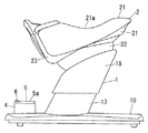
以下、本発明を添付図面に示す実施形態に基づいて説明する。図1には、本発明の実施形態における第1例の他動運動装置に使用者Uが乗って他動運動を行う様子を概略的に示している。なお、本文中に用いる上下、左右、前後等の各方向は、シート部2に着座した姿勢にある使用者Uから見た方向を基準とする。
Hereinafter, the present invention will be described based on embodiments shown in the accompanying drawings. FIG. 1 schematically shows a state in which a user U rides on a first example of a passive motion apparatus according to an embodiment of the present invention and performs a passive motion. In addition, each direction, such as up and down, left and right, and front and rear, used in the text is based on a direction viewed from the user U who is in a posture sitting on the
本例の他動運動装置は、使用者Uが臀部を置いて着座姿勢をとるためのシート部2と、このシート部2を支持しながら揺動させる駆動部3と、駆動部3を収納した揺動体1と、着座姿勢にある使用者Uが左右の足裏を置くために設置した左右一対のステップ部4と、これら揺動体1やステップ部4を支持する基台部10とで、主体を成している。
The passive motion apparatus of this example houses a
図8(a)に示すように、駆動部3はシート部2に対して、平面視で8の字を描き且つ側面視では前方に沈み込むとともに後方には浮き上がりながら戻るという、前後、左右、上下方向の揺動を組み合わせた軌跡を描かせる。上記軌跡に沿って、シート部2が左斜め前方に移動しながら下方に沈み込む際に、使用者Uに対して左足の踏み込み動作を行わせる。また、上記軌跡に沿って、シート部2が右斜め前方に移動しながら下方に沈み込む際に、使用者Uに対して右足の踏み込み動作を行わせる。左右の踏み込み動作を交互に行わせることで、使用者Uの左右の脚部の筋肉に刺激を与えることができる。シート部2に上記運動を行わせる駆動部3等の具体的な構造については、改めて詳述する。
As shown in FIG. 8 (a), the
左右の各ステップ部4は、使用者Uが足裏を置くことができるように上面5aを設けた板状の足置き部材5と、この足置き部材5において使用者Uの爪先側となる部分(つまり前端部分)を左右軸6中心に枢支するとともに踵側となる部分(つまり後端部分)が自由端となるように基台部10上に支持する支持体7と、該足置き部材5の下方への回動に対して抵抗を与える抵抗付与手段8とから成る。本例では上記抵抗付与手段8として足置き部材5をバネで支持させ、足置き部材5に対して上方への付勢力を付与するように設けているが、足置き部材5をエアバッグ、ジェルバッグ、ダッシュポット等で支持させた構造としてもよい。
Each of the left and
足置き部材5の上面5aには、使用者Uの足先が当たることで足裏位置を定める位置決め部9を設けている。上記位置決め部9により位置を定めた使用者Uの足裏は、その踵部分を除いた部分(使用者Uの足裏において爪先から足裏長さの1/3〜1/2程度までの部分)が足置き部材5の上面5aに当たるように設けている。
On the
足置き部材5は、所定範囲内で回動するものであって、図1中に実線で示す位置が、上記所定範囲のうち足置き部材5の踵側が最も下方となる位置(以下「最下端位置」という)であり、図1中に想像線で示す位置が、上記所定範囲のうち足置き部材5の踵側が最も上方となる位置(以下「最上端位置」という)である。上記足置き部材5を抵抗付与手段8の抵抗に抗して最上端位置から下方に押し込むと、抵抗付与手段8は足置き部材5に対して、足置き部材5の踵側が下方に回転して最下端位置に近づくほどに大きな抵抗(付勢力)を付与する。なお、上記のように抵抗付与手段8に抗して足置き部材5を押し込むのではなく、シート部2の揺動と同期して足置き部材5を自動的に回動させるように、抵抗付与手段8の代わりに適宜の駆動機構を設けてあってもよい。
The
上記構成の他動運動装置によれば、正面視において8の字状の軌跡を描きながら動作するシート部2が、例えば左斜め前方に移動しながら下方に沈み込んだ際には、着座姿勢にある使用者Uは、左側の足置き部材5の上面5aに置いた足裏を下方に押し込む踏み込み動作を他動的に行う。このとき、使用者Uの足先は爪先側を支点として踵側を下げるように動作し、図中に実線で示すように、足先を背屈させた(即ち、爪先側を甲側に持ち上げた)状態になる。
According to the passive motion apparatus having the above-described configuration, when the
この足先の背屈動作により、使用者Uの下半身全体はシート部2の揺動運動(矢印a参照)によって前方および下方に移動してステップ部4に接近するにも関わらず、使用者Uの左脚の膝部分については、前後方向にほとんど移動することなく下方に移動するようになっている。つまり、ステップ部4を上記構成に設けたことで、使用者Uの脚部の大腿部から膝部分に至る範囲に対しては左斜め前方に負荷がかかるが(矢印b参照)、膝部分から踵部分に至る範囲においては、左斜め前方にかかる負荷が下方に向けての負荷に変換されることになる(矢印c参照)。シート部2が揺動することで、使用者Uはこの踏み込み動作を左右交互に繰り返す。
Due to the dorsiflexion of the toes, the entire lower body of the user U moves forward and downward by the swinging motion of the seat portion 2 (see arrow a) and approaches the
したがって、使用者Uが膝角度を約90°にした状態で着座してシート部2の揺動運動を開始しても、踏み込み動作の際に使用者Uの膝が前後方向に大きく往復動して膝蓋骨(お皿)等に大きな負荷をかけることがない。そして、踏み込み動作の際に、使用者Uの大腿部に対しては特にその前側部分(領域P1参照)に対して負荷がかかり、大腿四等筋等を効果的に刺激して鍛えることができる。また、使用者Uの膝下部に対しては、特に後側部分(領域P2参照)に対して負荷がかかり、ひ腹筋等を効果的に刺激して鍛えることができる。なお、膝下部の後側部分に対しては、ひ複腹筋等の筋肉を伸ばしながら負荷をかけることによって、筋肉増強効果の高いエキセントリックトレーニングを行うことができる。
Therefore, even if the user U sits in a state where the knee angle is about 90 ° and starts swinging the
このように、本例の他動運動装置によれば、90°程度から開始するような深い膝角度θのもとで、膝の前後位置を略一定にして大きな負担をかけることなく他動的な踏み込み運動を行うことができる。しかも、特にひ腹筋等に対しては、効果の高いエキセントリックトレーニングを行うことが可能である。使用者Uの膝角度θは、足裏を踏み込んで足先が背屈した状態となったときに、例えば100°〜110°程度にまで広がる。上記膝角度θの設定は、踏み込み動作を繰り返す際に90°〜140°の範囲内で変化するように設定することが好ましい。 Thus, according to the passive motion apparatus of this example, under the deep knee angle θ starting from about 90 °, the front and rear positions of the knees are made substantially constant without imposing a heavy burden. You can perform a stepping exercise. Moreover, highly effective eccentric training can be performed particularly for the gastrocnemius muscle. The knee angle θ of the user U is widened to, for example, about 100 ° to 110 ° when the foot is depressed and the toes are bent back. The knee angle θ is preferably set so as to change within a range of 90 ° to 140 ° when the stepping motion is repeated.
加えて、本例の他動運装置においては、足置き部材5に当たって下方に押し込むことになる使用者Uの足裏部分が、踵部分を除く部分となっていることで、踏み込みの際に使用者Uの土踏まず部分(領域P3参照)が効果的に鍛えられる。即ち、使用者Uの脚部の領域P1,P2,P3が特に効果的に且つ同時に鍛えられるようになっている。
In addition, in the transfer device of this example, the sole portion of the user U who hits the
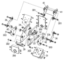
次に、シート部2の上記揺動運動を実現するための具体的構造について、図2〜図8に基づいて詳述する。駆動部3を収納する揺動体1は、図3に示すように、基台部10から斜め後方に向けて立ち上がる支柱12と、支柱12に対して該支柱12の長手方向にスライド自在に取り付けられる支持フレーム13と、支持フレーム13の上記スライドを電動で行う電動スライドユニット14とを備えたもので、支柱12の周囲を覆うカバー17、支持フレーム13の外周を覆う主カバー18等で外面を覆っている。
Next, a specific structure for realizing the swing motion of the
一方、シート部2は図2に示すように、座面カバー21、座面カバー21の下方側に連結されるカバー22、座面カバー21の左右に取り付けられる保護カバー23等で構成している。
On the other hand, as shown in FIG. 2, the
上記駆動部3は、図4〜図7に示すように、箱形に形成された可動フレーム30内に、モータ31とこのモータ31の回転を2つの出力軸32,33に伝えるギア群34とを配置するとともに、可動フレーム30の上方に位置する可動プレート40を2種のリンクプレート41,42で可動フレーム30に連結したものである。上記可動フレーム30は、その前後の端面の軸受け部300が揺動体1における上記支持フレーム13に軸130(図3参照)で軸回りに回動自在に連結されることで、揺動体1に取り付けられる。
As shown in FIGS. 4 to 7, the
ここで、可動プレート40の後端側に連結されるリンクプレート41は、可動フレーム30の後部側の側面に軸301で連結されたものであるのに対して、リンクプレート42は、可動フレーム30内に配されて軸302によって可動フレーム30に一端側が支持されている回動プレート39の他端側に軸303によって支持されている。また、リンクプレート42は、可動プレート40の前端側に伸縮アクチュエータ45を介して連結されている。
Here, the
そして、回転駆動される2つの出力軸32,33のうちの出力軸32は、可動フレーム30の外側面側に偏心部を位置させており、この偏心部がリンク35によって支持フレーム13に連結されてロール駆動部を構成している。
The
他方の出力軸33は、可動フレーム30の外側面側に2つの偏心部33a,33bを位置させており、偏心量が小さい偏心部33aは上記リンクプレート42に連結され、偏心量が大きい偏心部33bは一端をリンクプレート41に連結した連結リンク36に連結されて、ピッチ駆動部を構成している。
The
上記2つの出力軸32,33のうち、リンク35で支持フレーム13に連結されている出力軸32の偏心部の回転は、可動フレーム30を軸130(図6中の前後に傾いた前後軸A)の軸回りに往復回動させる。
Of the two
また、他方の出力軸33の偏心部33aの偏心回転はリンクプレート42と伸縮アクチュエータ45とを介して可動プレート40の前端側を前後及び上下に揺らし、偏心部33bの偏心回転は連結リンク36とリンクプレート41とを介して可動プレート40の後端側を主として前後に揺らす。この時、リンクプレート41と可動プレート40との連結軸40aの前後の揺れの軌跡をT1、上記伸縮アクチュエータ45と可動プレート40との連結軸40bの前後の揺れの軌跡をT2としたとき、図6中に矢印で示すように、両者のストロークは同じであるものの、上下成分が両軌跡T1,T2で異なるように設定している。
Further, the eccentric rotation of the
ちなみに上記軌跡T1は略前後に動くだけのものとなっているが、上記軌跡T2はリンクプレート42における軸303が軸40bよりも後方にずれた位置にあるために、前後に加えて上下に動く成分が多くなっている。しかも、可動プレート40の前端側の揺動駆動のための構成部品中に回動プレート39があって、リンクプレート42の回動支点となる軸303の位置を回動プレート39が上下させるために、軌跡T2は往路と帰路とで上下にずれたルートをとるようになっている。
Incidentally, the trajectory T1 only moves substantially back and forth, but the trajectory T2 moves up and down in addition to the front and rear because the
ここにおいて、前記シート部2は、出力軸32,33の回転に伴って前後左右に揺動駆動されることになる上記可動プレート40の上側に座面カバー21が固定されるものであり、このために可動プレート40と共にシート部2も前後左右の揺動を行うのであるが、左右の揺動の1サイクルの間に前後の揺動が2サイクル行われるように出力軸32,33の回転数を設定していることから、シート部2の座面カバー21における左右方向中央で且つ前後方向において最も低くなっている中央点21aは、上記前後左右の揺動によって、図8(a)に示すように平面視で8の字を横に(左右方向に)倒したような軌跡を描くものとなっている。また、軌跡T1,T2の違いにより、図8(b)に示すように、側面視において上記中央点21aが前方に沈み込むとともに浮き上がりながら後方に戻るという軌跡を描く。
Here, the
なお、本例では、上記のようにシート部2が8の字状に移動するように設定しているが、例えば、前後2回往復する際の後端位置を略一致するように設定した場合には、シート部2はV字状に移動することになる。また、左右1回の往復移動の間に前後4回往復する軌跡に設定した場合には、シート部2はW字状に移動するようになる。平面視におけるシート部2の軌跡としては、上記8の字、V字、W字等のいずれの軌跡であってもよい。
In this example, the
図8はシート部2の中央点の動きを所定時間間隔でプロットしたものであり、点の間隔が大であるところは速度が大、小さい間隔から大きな間隔に短時間に変化するところは加速度が大であることを示している。つまり、図8に示すものでは、前方への移動時の加速度が後退時の加速度よりも大となっている。したがって、着座姿勢でシート部2の動きを受ける使用者Uにしてみれば、前に進んでいるという感覚を受ける。
FIG. 8 is a plot of the movement of the center point of the
次に、本発明の実施形態における第2例の他動運動装置について、図9、図10に基づいて説明する。上記した第1例の他動運動装置と同様の構成については詳しい説明を省略し、第1例の他動運動装置とは相違する特徴的な構成についてのみ以下に詳述する。 Next, a second example of the passive motion apparatus according to the embodiment of the present invention will be described with reference to FIGS. A detailed description of the same configuration as that of the first example of the passive motion apparatus will be omitted, and only a characteristic configuration different from that of the first example of the passive motion apparatus will be described in detail below.
本例の他動運動装置においては、ステップ部4の位置を移動自在とする位置調整機構50を備えたことが特徴となっている。位置調整機構50は、シート部2やこれを揺動自在に支持する駆動部3に対して、ステップ部4を前後方向に移動自在(図中矢印参照)とするものである。
In passive exercise apparatus in this embodiment, it has become a feature having a
上記位置調整機構50として具体的には、図9に示すように、床面上に載置する基台部10を、ステップ部4を支持する前側基台部10aと、シート部2や駆動部3を支持する後側基台部10bとに分割し、前側基台部10aから後方に延設した左右一対の連結バー19を、後側基台部10bに設けた左右一対のレール20内にスライド自在に嵌合させている。連結バー19は角パイプであるが、丸型やコ字型のものであってもよい。
Specifically, as the
なお、複数段階のスライド位置で前側基台部10aを係止できるように、図10(a)に示すようにピン25を上方から嵌入させて連結バー19をレール20に固定するように設けてもよい。この場合、連結バー19には、ピン25を嵌入可能な孔部26を前後方向に所定距離を隔てた複数個所に設けておき、後側基台部10bには、ピン25をレール20内にまで挿通可能な挿通孔27を一つ備えておく。また、図示しないラッチ機構を用いて連結バー19をレール20に固定するようにしてもよい。
It should be noted that, as shown in FIG. 10A, the
また、図10(b)に示すように、クリック機構を用いて連結バー19を複数段階でレール20に仮固定するように設けてもよい。この場合、連結バー19には、左右両側方に膨出したクリック部28を設けておき、後側基台部10bのレール20の左右内側面には、内側に膨出したレール側クリック部29を前後方向に所定距離を隔てた複数個所に備えておく。連結バー19のクリック部28が、隣接するレール側クリック部29間に位置することで連結バー19はその前後位置に仮固定される。連結バー19に前後方向の外力を加えると、クリック部28はレール側クリック部29を弾性的に乗り越えてクリック感を付与しながら他の仮固定位置に移動する。
Further, as shown in FIG. 10 (b), the connecting
本例の他動運動装置によれば、ステップ部4の前後位置を変更することで、シート部2に着座して足置き部材5に足裏を置いた姿勢における使用者Uの膝角度θを、使用者Uの体型に応じた適切な角度に調整することができる。つまり、身長が高く足の長い使用者Uであればステップ部4を前方に位置させてシート部2から離し、身長が低く足の短い使用者Uであればステップ部4を後方に位置させてシート部2に近づけることにより、使用者Uの体型に関わらず運動開始時の膝角度θを約90°に設定することができる。なお、本例の他動運動装置においては、足置き部材5に使用者Uの足裏全体が当たるように設けている。
According to the passive motion apparatus of this example, the knee angle θ of the user U in the posture of sitting on the
次に、本発明の実施形態における第3例の他動運動装置について、図11〜図13に基づいて説明する。上記した第2例の他動運動装置と同様の構成については詳しい説明を省略し、第2例の他動運動装置とは相違する特徴的な構成についてのみ以下に詳述する。本例の他動運動装置の位置調整機構50は、シート部2やこれを揺動自在に支持する駆動部3に対して、ステップ部4を上下方向に移動自在(図中矢印参照)とするものである。
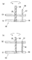
Next, a third example of the passive motion apparatus according to the embodiment of the present invention will be described with reference to FIGS. A detailed description of the same configuration as the above-described second-movement apparatus is omitted, and only a characteristic configuration that is different from the second-movement apparatus is described in detail below. The
上記位置調整機構50として具体的には、図12、図13に示すような固定板51と可動板52を有する昇降装置58を用い、基台部10に固定板51を固定するとともに、可動板52上にステップ部4を支持させる。図12に示す昇降装置58は、固定板51と可動板52の間にX字状のリンク53を介在させたパンタグラフ状のものである。リンク53を上下方向に伸縮させることで、可動板52ひいてはステップ部4が上下動する。また、図13に示す昇降装置58は、固定板51にネジ支柱54を軸中心に回動自在に立設するとともに該ネジ支柱54を可動板52のネジ孔55に螺合させ、更に、固定板51にガイドピン56を立設するとともに該ガイドピン56を可動板52のガイド孔57に貫通させたものである。ネジ支柱54を回動させることで、可動板52ひいてはステップ部4が上下動する。
Specifically, as the
本例の他動運動装置によれば、ステップ部4の上下位置を変更することで、シート部2に着座して足置き部材5に足裏を置いた姿勢における使用者Uの膝角度θを、使用者Uの体型に応じた適切な角度に調整することができる。つまり、身長が高く足の長い使用者Uであればステップ部4を下方に位置させてシート部2から離し、身長が低く足の短い使用者Uであればステップ部4を上方に位置させてシート部2に近づけることにより、使用者Uの体型に関わらず運動開始時の膝角度θを約90°に設定することができる。
According to the passive motion apparatus of this example, the knee angle θ of the user U in the posture of sitting on the
次に、本発明の実施形態における第4例の他動運動装置について、図14に基づいて説明する。上記した第1〜第3例の他動運動装置と同様の構成については詳しい説明を省略し、第1〜第3例の他動運動装置とは相違する特徴的な構成についてのみ以下に詳述する。 Next, a fourth example of the passive motion apparatus according to the embodiment of the present invention will be described with reference to FIG. Detailed description of the same configuration as the above-described first and third examples of the passive motion apparatus will be omitted, and only the characteristic configuration different from the first to third examples of the passive motion apparatus will be described in detail below. To do.
本例の他動運動装置の位置調整機構50は、シート部2やこれを揺動自在に支持する駆動部3に対して、ステップ部4を前後方向および上下方向に移動自在(図中矢印参照)とするものである。位置調整機構50として具体的には、第2例の前後スライド自在に設けた構造と、第3例の上下動自在に設けた構造とを、組み合わせた構造になっている。
The
本例の他動運動装置によれば、ステップ部4の前後位置と上下位置の両方または片方を変更することで、シート部2に着座して足置き部材5に足裏を置いたときの使用者Uの姿勢や、このときの使用者Uの膝角度θを、使用者Uの体型に応じた適切なものに調整することができる。
According to the passive motion apparatus of the present example, the
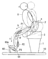
次に、本発明の実施形態における第5例の他動運動装置について、図15に基づいて説明する。上記した第1例の他動運動装置と同様の構成については詳しい説明を省略し、第1例の他動運動装置とは相違する特徴的な構成についてのみ以下に詳述する。 Next, a fifth example of the passive motion apparatus according to the embodiment of the present invention will be described with reference to FIG. A detailed description of the same configuration as that of the first example of the passive motion apparatus will be omitted, and only a characteristic configuration different from that of the first example of the passive motion apparatus will be described in detail below.
本例の他動運動装置においては、ステップ部4が、使用者Uが足裏の爪先側(つまり足指部分)を乗せる先乗せ部60と、使用者Uの足裏であって上記先乗せ部60に乗せた部分を除く部分(つまり足指部分よりも踵側の部分)を乗せて下方から弾性的に支持する柔軟部材61とから成る点に、特徴を有している。
In the passive motion apparatus of the present example, the
上記先乗せ部60は、基台部10に立設したものであって、その先端部分には、使用者Uが足裏の指先部分を引掛けることのできる引掛け部分60aを設けている。また、上記柔軟部材61は、先乗せ部60に隣接して基台部10上に支持されるバッグ状のものである。柔軟部材61に負荷をかけて下方に押し込むと、柔軟部材61は弾性変形をして背を低くするとともに、背が低くなるほどに下方への押し込みに対して大きな抵抗(付勢力)を付与する。なお、上記柔軟部材61としてはエアバッグを用いているが、肌当たりの良好な部材であればジェルバッグ等の他の部材を用いてもよい。
The front-
上記構成の他動運動装置によれば、シート部2の揺動によって他動的に踏み込み動作を行う際に、使用者Uの足先は先乗せ部60の引掛け部分60aを支点として踵側を下げるように動作し、図中に実線で示すように、足先を背屈させた状態になる。この足先の背屈動作により、本例の他動運動装置においても、90°程度から開始するような深い膝角度θのもとで、膝の前後位置を略一定にして大きな負担をかけることなく他動的な踏み込み運動を行うことができる。また、特にひ腹筋等に対しては、効果の高いエキセントリックトレーニングを行うことが可能である。そして、足裏に当たる部分がバッグ状の柔軟部材61であるから、使用者Uにとっては心地よい押し込み感を得ることができる。
According to the passive movement apparatus having the above-described configuration, when the stepping operation is performed dynamically by swinging the
なお、本例の他動運装置においては、柔軟部材61に対して足裏の踵部分を含んだ大半の部分が当たって下方に押し込むようになっているが、第1例の他動運動装置の足置き部材5と同様に、上記柔軟部材61を、使用者Uの足裏の踵部分を除く部分が当たるように形成してもよい。この場合には、踏み込みの際に使用者Uの土踏まず部分(領域P3参照)を効果的に鍛えることができる。また、本例の他動運動装置においても、第2〜4例に示したような位置調整機構50を具備することは、使用者Uの体型にあわせて膝角度θを調整する点で好ましい。更に、柔軟部材61を足裏で押し込むことでのみ背を低くするのではなく、柔軟部材61であるエアバッグに給排気することで、シート部2の揺動と同期して柔軟部材61を自動的に膨縮させる構造にしてもよい。
In this embodiment, the most part including the heel portion of the sole hits against the
ところで、上記した第1例〜第5例の各例の他動運動装置においては、駆動部3はシート部2を前後方向および上下方向に往復動させる構造になっているが、前後方向にのみ往復動させる構造や、或いは上下方向にのみ往復動させる構造であってもよい。このようにシート部2を前後方向または上下方向にのみ往復動させる構造においても、本発明のステップ部4等の構成を採用することで、90°程度から開始するような深い膝角度θのもとで、膝の前後位置を略一定にして大きな負担をかけることなく他動的な踏み込み運動を行うことができる。また、特にひ腹筋等に対しては、効果の高いエキセントリックトレーニングを行うことが可能になる。
By the way, in the passive motion apparatus of each of the first to fifth examples described above, the
この場合の駆動部3の構造は、シート部2を前後方向または上下方向にのみ往復動させるものであれば、どのような構造を用いてもよい。例えば、第1例で図2〜図8に基づいて説明した構造の駆動部3を基にしてシート部2を前後方向にのみ往復動させようとする場合には、リンク35を取り外したうえで可動フレーム30を主カバー18等に固定して左右方向の揺動を禁止し、更に、リンクプレート42を取り外したうえで伸縮アクチュエータ45の下端部を可動フレーム30等に支持させて上下方向の揺動を禁止すればよい(図6、図7等参照)。
As the structure of the
また、例えば、第1例で図2〜図8に基づいて説明した構造の駆動部3を基にしてシート部2を上下方向にのみ往復動させようとする場合には、リンク35を取り外したうえで可動フレーム30を主カバー18等に固定して左右方向の揺動を禁止し、更に、連結リンク36を取り外したうえでリンクプレート41を可動フレーム30等に固定して前後方向の揺動を禁止すればよい(図6、図7等参照)。また、伸縮アクチュエータ45を用いてシート部2を上下動させてもよい。
Further, for example, when the
2 シート部
3 駆動部
4 ステップ部
5 足置き部材
8 抵抗付与手段
50 位置調整機構
60 先乗せ部
61 柔軟部材
U 使用者
2
Claims (4)
Priority Applications (3)
| Application Number | Priority Date | Filing Date | Title |
|---|---|---|---|
| JP2008109440A JP4656178B2 (en) | 2008-04-18 | 2008-04-18 | Passive motion device |
| US12/922,393 US20110046524A1 (en) | 2008-04-18 | 2009-04-17 | Passive exercise apparatus |
| PCT/JP2009/058115 WO2009128565A1 (en) | 2008-04-18 | 2009-04-17 | Passive exercise apparatus |
Applications Claiming Priority (1)
| Application Number | Priority Date | Filing Date | Title |
|---|---|---|---|
| JP2008109440A JP4656178B2 (en) | 2008-04-18 | 2008-04-18 | Passive motion device |
Publications (2)
| Publication Number | Publication Date |
|---|---|
| JP2009254700A JP2009254700A (en) | 2009-11-05 |
| JP4656178B2 true JP4656178B2 (en) | 2011-03-23 |
Family
ID=40756365
Family Applications (1)
| Application Number | Title | Priority Date | Filing Date |
|---|---|---|---|
| JP2008109440A Expired - Fee Related JP4656178B2 (en) | 2008-04-18 | 2008-04-18 | Passive motion device |
Country Status (3)
| Country | Link |
|---|---|
| US (1) | US20110046524A1 (en) |
| JP (1) | JP4656178B2 (en) |
| WO (1) | WO2009128565A1 (en) |
Families Citing this family (10)
| Publication number | Priority date | Publication date | Assignee | Title |
|---|---|---|---|---|
| US8430796B1 (en) | 2012-05-29 | 2013-04-30 | Mary Anne Tarkington | Exercise devices and methods for exercising an ankle, foot, and/or leg |
| EP3274059B1 (en) * | 2015-03-24 | 2021-04-07 | Fondazione Istituto Italiano di Tecnologia | Driving system for controlling the rotation of an object about two perpendicular axes of rotation and rehabilitation machine for rehabilitation of the lower limbs and the trunk incorporating such a driving system |
| CA3092212A1 (en) | 2018-02-26 | 2019-08-29 | Ts Medical Llc | Devices and methods for exercising an ankle, foot, and/or leg |
| US11638852B2 (en) | 2018-04-06 | 2023-05-02 | TS Medical, LLC | Portable devices for exercising muscles in the ankle, foot, and/or leg, and related methods |
| JP2019202626A (en) * | 2018-05-23 | 2019-11-28 | トヨタ紡織株式会社 | Vehicle seat device |
| CA3055361A1 (en) | 2018-09-14 | 2020-03-14 | Mary Anne Tarkington | Portable devices for exercising muscles in the ankle, foot, and/or leg, and related methods |
| USD961023S1 (en) | 2020-02-12 | 2022-08-16 | TS Medical, LLC | Excercise device |
| USD1012207S1 (en) | 2020-08-12 | 2024-01-23 | TS Medical, LLC | Exercise device |
| CN114733155A (en) * | 2022-03-29 | 2022-07-12 | 鲁山健民医院 | Cardiovascular and cerebrovascular rehabilitation training instrument based on traditional Chinese medicine |
| CN114515416B (en) * | 2022-03-30 | 2023-01-24 | 重庆市中医院 | Ankle rehabilitation training device |
Citations (2)
| Publication number | Priority date | Publication date | Assignee | Title |
|---|---|---|---|---|
| JP2004141292A (en) * | 2002-10-23 | 2004-05-20 | Takachiho Sangyo:Kk | Stepper exercise machine |
| WO2004110568A1 (en) * | 2003-05-21 | 2004-12-23 | Matsushita Electric Works, Ltd. | Leg portion training device |
Family Cites Families (11)
| Publication number | Priority date | Publication date | Assignee | Title |
|---|---|---|---|---|
| US2915055A (en) * | 1957-03-13 | 1959-12-01 | Edwin Braverman | Exercising chair |
| GB1139665A (en) * | 1967-04-14 | 1969-01-08 | Frank Albert Halford | Power driven exerciser |
| US5267923A (en) * | 1991-07-24 | 1993-12-07 | Gary Piaget | Reciprocating bellows operated exercise machine |
| US5722917A (en) * | 1996-09-18 | 1998-03-03 | Exerfun, Inc. | Displaceable seat exercise system |
| US6467197B1 (en) * | 1999-05-31 | 2002-10-22 | Asics Corp. | Shoe with arch reinforcement |
| US7070415B2 (en) * | 2000-06-07 | 2006-07-04 | Matsushita Electric Works, Ltd. | Balance training device |
| US7806805B2 (en) * | 2003-10-27 | 2010-10-05 | Stamina Products, Inc. | Exercise apparatus with resilient foot support |
| US7195583B2 (en) * | 2004-05-21 | 2007-03-27 | Leib Roger K | Posture and exercise seating |
| US7775941B2 (en) * | 2004-12-07 | 2010-08-17 | The Boeing Company | Exercise apparatus for transport vehicles and related methods |
| TWM285363U (en) * | 2005-05-25 | 2006-01-11 | Jong-Jyr Kau | Improvement of steps machine structure |
| KR101138660B1 (en) * | 2006-12-25 | 2012-04-19 | 파나소닉 주식회사 | Exercise assisting device |
-
2008
- 2008-04-18 JP JP2008109440A patent/JP4656178B2/en not_active Expired - Fee Related
-
2009
- 2009-04-17 US US12/922,393 patent/US20110046524A1/en not_active Abandoned
- 2009-04-17 WO PCT/JP2009/058115 patent/WO2009128565A1/en active Application Filing
Patent Citations (2)
| Publication number | Priority date | Publication date | Assignee | Title |
|---|---|---|---|---|
| JP2004141292A (en) * | 2002-10-23 | 2004-05-20 | Takachiho Sangyo:Kk | Stepper exercise machine |
| WO2004110568A1 (en) * | 2003-05-21 | 2004-12-23 | Matsushita Electric Works, Ltd. | Leg portion training device |
Also Published As
| Publication number | Publication date |
|---|---|
| US20110046524A1 (en) | 2011-02-24 |
| WO2009128565A1 (en) | 2009-10-22 |
| JP2009254700A (en) | 2009-11-05 |
Similar Documents
| Publication | Publication Date | Title |
|---|---|---|
| JP4656178B2 (en) | Passive motion device | |
| KR200477442Y1 (en) | A massage chair | |
| EP2263761A1 (en) | Exercise apparatus | |
| KR101486187B1 (en) | A massage chair | |
| JP4816795B2 (en) | Passive exercise equipment | |
| TW200934556A (en) | Passive exercise apparatus | |
| KR20100108410A (en) | Standing-position type passive exercise machine | |
| JP2022058808A (en) | Massage machine | |
| KR101652334B1 (en) | Upper limb and Lower limb Rehabilitation Motion Device of Upright Type | |
| JP2020054573A (en) | Heel falling device | |
| KR20100132523A (en) | Exercise apparatus | |
| JP2008264319A (en) | Exercise assisting apparatus | |
| JP6804071B1 (en) | Heel stimulator | |
| JP2013017637A (en) | Exercise assisting apparatus | |
| JP2012005718A (en) | Passive exercise apparatus | |
| KR200334080Y1 (en) | Ankle pump healthy apparatus | |
| KR200494900Y1 (en) | Fitness device | |
| JP2005211323A (en) | Muscle training apparatus | |
| JP2020110377A (en) | Exercise apparatus | |
| JP2015134126A (en) | massage machine | |
| JP3866753B2 (en) | Massage machine | |
| KR100512906B1 (en) | Ankle pump healthy apparatus | |
| JP2011110324A (en) | Chair massage machine | |
| KR20100136511A (en) | Exercise aiding apparatus | |
| JP4831021B2 (en) | Oscillating motion device |
Legal Events
| Date | Code | Title | Description |
|---|---|---|---|
| RD04 | Notification of resignation of power of attorney |
Free format text: JAPANESE INTERMEDIATE CODE: A7424 Effective date: 20100811 |
|
| A131 | Notification of reasons for refusal |
Free format text: JAPANESE INTERMEDIATE CODE: A131 Effective date: 20100907 |
|
| A521 | Request for written amendment filed |
Free format text: JAPANESE INTERMEDIATE CODE: A523 Effective date: 20101108 |
|
| TRDD | Decision of grant or rejection written | ||
| A01 | Written decision to grant a patent or to grant a registration (utility model) |
Free format text: JAPANESE INTERMEDIATE CODE: A01 Effective date: 20101130 |
|
| A01 | Written decision to grant a patent or to grant a registration (utility model) |
Free format text: JAPANESE INTERMEDIATE CODE: A01 |
|
| A61 | First payment of annual fees (during grant procedure) |
Free format text: JAPANESE INTERMEDIATE CODE: A61 Effective date: 20101213 |
|
| FPAY | Renewal fee payment (event date is renewal date of database) |
Free format text: PAYMENT UNTIL: 20140107 Year of fee payment: 3 |
|
| FPAY | Renewal fee payment (event date is renewal date of database) |
Free format text: PAYMENT UNTIL: 20140107 Year of fee payment: 3 |
|
| LAPS | Cancellation because of no payment of annual fees |