JP4654302B2 - Video information receiving apparatus, video information receiving method, and video information transmitting / receiving method - Google Patents
Video information receiving apparatus, video information receiving method, and video information transmitting / receiving method Download PDFInfo
- Publication number
- JP4654302B2 JP4654302B2 JP2009102556A JP2009102556A JP4654302B2 JP 4654302 B2 JP4654302 B2 JP 4654302B2 JP 2009102556 A JP2009102556 A JP 2009102556A JP 2009102556 A JP2009102556 A JP 2009102556A JP 4654302 B2 JP4654302 B2 JP 4654302B2
- Authority
- JP
- Japan
- Prior art keywords
- output
- video information
- information
- resolution
- receiving
- Prior art date
- Legal status (The legal status is an assumption and is not a legal conclusion. Google has not performed a legal analysis and makes no representation as to the accuracy of the status listed.)
- Expired - Lifetime
Links
Images


Description
本発明は、映像情報を入力し外部装置へ出力する際、入力した映像情報に対し著作権を保護するため、解像度等を制御して出力する入出力装置に関する。さらに本発明は、このような制御を行なうのに好適な映像情報の記録媒体に関する。 The present invention relates to an input / output device that controls and outputs a resolution or the like in order to protect copyright of input video information when the video information is input and output to an external device. Furthermore, the present invention relates to a video information recording medium suitable for performing such control.
テレビジョン放送や情報ソフトサービスの分野においては、ディジタル放送やHD(High Definition:高精細)放送が開始された。これにより、放送の多チャネル化が可能となっただけでなく、映像音声情報の品質が大幅に向上した。これに対応した高品質な情報ソフトも、今後現れるであろう。 In the fields of television broadcasting and information software services, digital broadcasting and HD (High Definition) broadcasting have been started. As a result, not only multi-channel broadcasting is possible, but the quality of video / audio information has been greatly improved. Corresponding high-quality information software will appear in the future.
近年のディジタル技術による品質向上は様々な装置で効果をあげているが、これに伴う新たな問題も発生している。特に、情報を記録再生する機器でディジタル記録方式を用いることにより、良質なダビングソフトが著作権者の預かり知らぬところで出回ってしまい、利益が権利者へ還元できなくなる問題がある。これは、民生用のディジタル・オーディオ・レコーダが現れた時に問題となって以来、各方面で対応策が検討されてきた。たとえば、特開平11−146378号公報では、情報を記録するに際して、故意に品質を劣化させて記録することが開示されている。 Improvements in quality by digital technology in recent years have been effective in various devices, but new problems have also occurred. In particular, by using a digital recording method in a device that records and reproduces information, there is a problem that good quality dubbing software circulates in a place unknown to the copyright holder and profits cannot be returned to the right holder. Since this became a problem when consumer-use digital audio recorders appeared, countermeasures have been studied in various directions. For example, Japanese Patent Application Laid-Open No. 11-146378 discloses that information is intentionally deteriorated in quality when recorded.
映像情報記録機器の場合、ディジタル出力信号は、これを暗号化して特定のユーザにしか視聴させない方法、または制御データを多重して不正な記録を禁止する方法が開発されており、秘匿度が高い。最も問題となるのはアナログ出力信号である。アナログ出力は、類似の方法を適用するとしても手段が限られており、かつ破られ易い。このため、ある程度高品質な情報を特にアナログ出力する際は、出力する以前に品質を劣化させることが、著作権者の権利保護上は有効である。 In the case of video information recording equipment, a digital output signal is encrypted so that only a specific user can view it, or a method of multiplexing control data and prohibiting unauthorized recording has been developed, and has high confidentiality. . The most problematic is the analog output signal. Even if a similar method is applied to analog output, means are limited and it is easily broken. For this reason, when outputting high quality information to an analog level in particular, it is effective in protecting the copyright holder's rights to deteriorate the quality before outputting.
しかし、当然ながらユーザの観点から言えば、劣化させるのはある限度にとどめるべきであり、折角HD放送で得た映像を、解像度でたとえば半分以下などとしては、視聴する際に不満足である。これらの条件を踏まえ、これに相応しい方法を具体的に提案したものは、これまでなかった。 However, of course, from the user's point of view, degradation should be limited to a certain limit, and if the video obtained by the corner HD broadcast is, for example, less than half the resolution, it is unsatisfactory when viewed. Based on these conditions, there has never been a concrete proposal of a method suitable for this.
本発明の目的は、特に高品質な映像情報を記録再生しまた出力するに際し、著作権者の権利保護とユーザの利益の双方に適った品質制限を行なう映像情報入出力装置、またこれに好適な記録媒体を提供することにある。 An object of the present invention is to provide a video information input / output device that performs quality restriction suitable for both copyright protection and user's interest, especially when recording / reproducing and outputting high-quality video information, and also suitable for this. Is to provide a simple recording medium.
[課題を解決するための手段]
上記課題を達成するために本発明の一実施の態様は、例えば特許請求の範囲に記載され
ている技術的思想を用いればよい。
[Means for solving problems]
In order to achieve the above object, an embodiment of the present invention is described in, for example, the claims.
The technical idea that is used may be used.
以上説明したとおり本発明によれば、高精細(HD)映像情報など情報量の多いものを、特にアナログ情報として出力する際に、ある程度の解像度などの制限を施せるため、良質な複製を作成することが困難となり、著作権者などの権利を保護することができる。 As described above, according to the present invention, when a large amount of information such as high definition (HD) video information is output as analog information in particular, a certain degree of resolution or the like can be restricted, so a high-quality copy is created. This makes it difficult to protect the rights of copyright holders .
本発明の一実施形態においては、たとえば放送局などの情報提供部から伝送する情報、あるいは記録媒体などに記録された情報ソフト内に、上記したような特にアナログ出力に対する解像度などの制限を施すか否かを指示する制御情報を多重する。たとえば、施す場合を0、しない場合を1とするなどして、基本的には1ビットで多重できる。この解像度などの制限により、HDの情報は、NTSC、PALなど旧来からのテレビジョン方式に相当するSD(Standard Definition:標準精細)並みかそれに近い情報に変えられる。また、一度解像度制限を行って出力したものを、ディスプレイへ表示する際は、走査線を補間するなどして、HD情報並みの走査線数に変えて表示することも考慮する。さらに、HD情報を特にアナログ出力の形で装置から出力する時の解像度制限の目安の条件として、1フレーム当たりの画素数を現在のSD情報並みの50万画素程度とする。これは従来から標準的に用いられた基準で表せば、垂直(走査線数)480×水平853画素、あるいは、垂直540×水平960画素などに相当する。また、表示する際ユーザに課金をし、これに応じた場合はこの解像度制限を解除する。あるいは支払い金額に応じて、段階的に解除するようにする。解像度制限は、主にアナログ出力に対して行う場合を述べるが、必要に応じて、ディジタル出力に対して行っても良い。 In one embodiment of the present invention, for example, whether the resolution for the analog output described above is restricted in the information transmitted from the information providing unit such as a broadcasting station or the information software recorded on the recording medium. The control information indicating whether or not is multiplexed. For example, it is possible to multiplex with 1 bit basically by setting 0 to apply and 1 to not. Due to the limitation of resolution and the like, the HD information can be changed to information similar to or similar to SD (Standard Definition) corresponding to the conventional television system such as NTSC and PAL. In addition, when displaying the output once the resolution is limited, it is also considered to change the number of scanning lines to the same level as the HD information by interpolating the scanning lines. Further, the number of pixels per frame is set to about 500,000 pixels, which is the same level as the current SD information, as a condition for resolution limitation when outputting HD information from the apparatus in the form of analog output. This is equivalent to vertical (number of scanning lines) 480 × horizontal 853 pixels, vertical 540 × horizontal 960 pixels, or the like, when expressed by a standard that has been used as a standard. In addition, the user is charged for the display, and the resolution restriction is canceled when the user is charged. Alternatively, it is canceled in stages according to the payment amount. Although the case where the resolution limitation is mainly performed on the analog output will be described, it may be performed on the digital output as necessary.
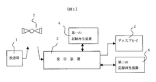
図1は、本発明の映像情報送受信システム全体の一実施形態を示すブロック図であって、放送で情報を送受信し、また記録再生する場合を示す。このシステムでは、本発明による解像度などを制限する方式を採用している。1は放送局などの情報提供局(送信装置)、2は中継局、3は受信装置(入出力装置)、4は第一の記録再生装置、5はディスプレイ、6は第二の記録再生装置である。なお本発明は、第一の記録再生装置4と第二の記録再生装置6のいずれか一方、または双方とも存在しない場合も適用でき、その範疇にある。
FIG. 1 is a block diagram showing an embodiment of the entire video information transmission / reception system of the present invention, and shows a case where information is transmitted / received by broadcasting and recorded / reproduced. This system employs a method for limiting the resolution and the like according to the present invention. 1 is an information providing station (transmitting device) such as a broadcasting station, 2 is a relay station, 3 is a receiving device (input / output device), 4 is a first recording / reproducing device, 5 is a display, and 6 is a second recording / reproducing device. It is. The present invention can also be applied to the case where either one or both of the first recording / reproducing
放送局など情報提供局1は、たとえば放送用衛星などの中継局2を介して、情報によって変調された信号電波を伝送する。もちろん、それ以外の、たとえばケーブルによる伝送、電話線による伝送、地上波放送による伝送などを用いても良い。受信側の受信装置3で受信されたこの信号電波は、後に述べるように、復調されて情報信号となった後、第一の記録再生装置4ないし第二の記録再生装置6へ記録するに適した信号となって記録され、また、ディスプレイ5へ送られる。ここでユーザは、情報内容を直接視聴することができる。また、上記した記録再生装置のうち、少なくも第一の記録再生装置4で再生された情報は、受信装置3を介してディスプレイ5へ与えられ、元の映像音声などの情報が視聴される。第二の記録再生装置6で再生された情報も、必要に応じて、受信装置3を介してディスプレイ5へ与えることができる。取外し可能な記録媒体へ予め記録した情報が提供される時は、これを取付けた第一の記録再生装置4ないし第二の記録再生装置6での再生動作以降が行われる。
An
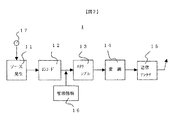
図2は、図1における放送局などの情報提供局1の構成の一例を示すブロック図である。11はソース発生部、12はMPEG方式等で圧縮を行うエンコード回路、13はスクランブル回路、14は変調回路、15は送信アンテナ、16は管理情報付与回路、17は入力端子である。
FIG. 2 is a block diagram showing an example of the configuration of the
カメラ、記録再生装置などから成るソース発生部11で発生した映像音声などの情報は、より少ない占有帯域で伝送できるよう、エンコード回路12でデータ量の圧縮が施され、必要に応じてスクランブル回路13で特定の視聴者のみが視聴可能となるように暗号化され、変調回路14で伝送するに適した信号となるよう変調された後、送信アンテナ15から、たとえば放送用衛星などの中継局に向けて電波として発射される。この際、管理情報付与回路16からは前記した解像度などの制限情報を始め、コピー制御情報、現在時刻等の情報を付加する。また入力端子17からは、先の図1では記さなかったが、たとえばリクエスト情報が電話回線などを介して入力される。これはビデオオンデマンドなど、視聴者のリクエストに応えて、送出する情報を決定するシステムで活用される。
Information such as video and audio generated by the
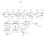
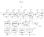
図3は、図1における受信装置(入出力装置)3の構成の一例を示すブロック図である。301はRF/IF変換回路、302は復調回路、303は誤り訂正回路、304は信号に施された暗号を解除するデスクランブル回路、305は第一のデマルチプレクス回路、306は入出力端子、307は第二のデマルチプレクス回路、308はデコード回路、309,310は出力端子、311は受信装置3全体の制御回路、312は情報管理回路、313は課金情報管理回路、314はモデム(MODEM)回路、315は出力端子、316は入力端子、317はコマンド入力回路である。図中、実線は映像音声など主となる情報の流れを、点線は各構成要素間の制御信号情報の流れを示す。
FIG. 3 is a block diagram showing an example of the configuration of the receiving device (input / output device) 3 in FIG. 301 is an RF / IF conversion circuit, 302 is a demodulation circuit, 303 is an error correction circuit, 304 is a descrambling circuit for canceling the encryption applied to the signal, 305 is a first demultiplexing circuit, 306 is an input / output terminal, 307 is a second demultiplexing circuit, 308 is a decoding circuit, 309 and 310 are output terminals, 311 is a control circuit for the
まず、実線で示した映像音声などの情報の流れを説明する。RF/IF変換回路301には、たとえば放送用衛星などの中継局2からの電波が入力される。ここでRF帯域の電波はIF帯域(Intermediate Frequency)に周波数変換され、また受信チャネルに依存しない一定の帯域の信号となり、復調回路302で伝送のために施された変調操作が復調される。さらに誤り訂正回路303で、伝送途中で発生した符合の誤りが検出さらには訂正された後、デスクランブル回路304で暗号の解除を行う。その後、第一および第二のデマルチプレクス回路305および307へ送られる。特にディジタル放送の場合、一つのチャネルには複数の情報が、時分割、スペクトラム拡散などの方法で多重されるのが普通である。デマルチプレクス回路は、これから所望の情報だけを分離するものである。第一、第二とこれを二つ設ける理由は、いわゆる裏番組記録を可能にするのみならず、第一のデマルチプレクス回路305で、記録に値しない情報を除去するためである。すなわち、情報の中には天気予報、番組の放送予定などの付加情報が付されていることが多く、これは放送時点で見るなら良いが、記録して後日見るには値しないため、ここで除去することも可能にしている。
First, the flow of information such as video and audio indicated by solid lines will be described. For example, radio waves from the
第一のデマルチプレクス回路305の出力は、入出力端子306へ与えられ、ここに接続される第一の記録再生装置4と信号の授受を行う。入出力端子306は双方向の端子であって、第一の記録再生装置4との間で、記録再生する情報を、たとえばディジタルデータで授受する。もちろん必ずしも一本の情報ラインが双方向となっていなくとも良く、複数の単方向情報ラインで構成されていても良い。さきの第二のデマルチプレクス回路307には、デスクランブル回路304から送られた情報あるいは、入出力端子306からの第一の記録再生装置4で再生された情報が接続されており、そのいずれか視聴したい情報が選択されてデコード回路308に入力される。
The output of the
次のデコード回路308では、伝送前に施された動画像のデータ圧縮がデコードされ、さらには必要に応じて、後述するように本発明による方法で、装置から出力するに適するよう変換して、出力端子309へ出力され、外部のディスプレイ5へ送られる。また、出力端子310へ出力する情報は、必要に応じてここに接続される第二の記録再生装置6へ与えられる。この装置は、たとえば旧来のSD情報用に作られたものであって、NTSC、PAL用などの汎用アナログ記録VTRがその代表的なものである。これに記録再生できるよう、デコード回路308では、情報がたとえばHD情報であるならば、SD情報のフォーマットへダウンコンバートして出力端子310へ与えるようにする。
In the
次に点線で示した制御信号に関して述べる。制御回路311は、上記した301より305、307、308の各構成要素との間で制御信号の授受を行い、受信装置3の全体が所望の動作を行うように制御する。このうちデコード回路308へ与えられるものは、後述するように、解像度などを制限する動作も制御する。
Next, control signals indicated by dotted lines will be described. The
情報管理回路312は、制御回路311が制御を行う時の管理データを、要求に応じて供給する。たとえば、ここには受信契約の情報が管理されている。ユーザが視聴したいチャネルを指定した時、この指定は入力端子316から入力され、コマンド入力回路317を介して制御回路311に送られる。制御回路311は、情報管理回路312に受信契約情報を要求する。ユーザが指定したチャネルと契約があると判断した場合、上記した各構成要素に制御信号を送り、該当チャネルの受信動作を指示する。また、情報管理回路312には、ユーザによるタイマ予約情報が管理されている。視聴を予約した時間になると、制御回路311は上記した各構成要素に制御信号を送り、受信動作を開始させる。
The
また制御回路311は、課金情報管理回路313との間でも制御信号の授受を行う。本発明における課金情報管理回路313の動作、特に課金方法については後述するが、ユーザへの課金が発生した場合には、この情報がモデム回路314へ与えられる。ここでさらに、電話回線など通信伝送路へ送出するに適した情報となって、出力端子315へ出力される。その後、通信伝送路を経て著作権者、金融機関あるいは図1の情報提供局1などへ送られ、規定の金額をユーザから得られるようにする。勿論、通信伝送路は無線であっても良い。
The
なお、図1の中継局2、第一の記録再生装置4、ディスプレイ5、第二の記録再生装置6は、それぞれ情報電波を中継するもの、情報を記録再生し、ないし表示するものというだけの認識で本発明は理解できるため、内部動作の詳しい説明は行わない。なお第一の記録再生装置4は、ディジタル伝送あるいは放送された圧縮ビットストリームをそのまま記録する、主には最近の、あるいは今後現れるディジタル記録方式によるものが相応しく、この場合、受信装置3との情報の授受は、前記したとおりディジタルで行うのが良い。また、その記録媒体はテープのみならず、ディジタルビデオディスクなどの取外し可能なディスク、ハードディスクなどの装置に内蔵されたディスクなど、様々なものが可能である。HD情報を扱う場合、ディスプレイ5はたとえば1000本以上の走査線数を有するものが最も相応しい。第二の記録再生装置6は特に限定はしないが、前記したとおり、SD情報に対応したアナログ記録の装置であっても良い。
Note that the
次に図4は、本発明における制御情報信号の一構成例を示すブロック図であり、その多くは、図2の情報提供局1の管理情報付与回路16で発生されて伝送され、記録再生装置、特に図1の第一の記録再生装置4で記録媒体へ記録される。これはたとえばテープ媒体の場合、一つの記録トラックに一個記録されれば充分であるが、当然ながら映像音声などの情報データとは決まった関係で記録され、再生時容易に分離できるようになされる。
Next, FIG. 4 is a block diagram showing an example of the configuration of the control information signal in the present invention, most of which is generated and transmitted by the management
プログラム番号100は、その媒体で何番目のプログラムであるかを示す。セクタ情報101は、プログラムを所定の単位で分割したセクタの番号である。分割は、固定の単位、たとえば2kバイト単位に分割してもよいし、情報の一定単位、たとえば、エンコードする時の分割の単位でもよい。また、番号はプログラム内で付けてもよいし、記録媒体全体での通し番号でもよい。後述する記録時刻106等の情報は、このセクタ単位で付加される。時間情報102は、その記録部分がそのプログラム開始後、どれだけ経ているかを示す。種類103は、そのプログラムが販売されたものか、レンタルか、自作か、放送からかなどの属性情報を示す。
The
コピー制御104は、その情報を媒体に記録して良いか否かを示す。Copy Never,Copy One Generation,Copy No More,Copy Freeといった指定がある。順に、記録複製の禁止、一世代のみ記録複製の許可、一世代の記録複製済のためこれ以上は不許可、記録複製の許可を意味する。Copy No MoreはCopy One Generationの信号を記録するときに、これ以上複製を許さないという意味で用いられる。Copy Never、Copy One Generation、Copy Freeの指定は、情報の製作者など著作権者が決めるものであって、これらにCopy No Moreを加えて計4つなので、2ビットの情報で伝送できる。
The
APS105は後述するところの、アナログ記録機器へのコピー制御情報(APS;Analogue Protection System)であり、アナログ映像信号への擬似シンクパルスの追加等によりコピーの可否を制御する。これにより、図3の入出力端子306と出力端子310の信号に対し、別々のコピー制御を行うことができる。
記録時刻106は、たとえば、図2の管理情報付与回路16で与えられた時刻を記録する。記録時刻106の記録は、たとえばセクタ単位で行われる。視聴期間107は、媒体に記録した情報の視聴に関し、時間制限を設ける場合に付加される。これも、さきの管理情報付与回路16で与えられることが多い。この時間制限のために、さきの記録時刻106を活用して良い。
As the
108は、前記したHD情報かSD情報など、その情報が用いている放送方式を示す。109は、本発明で用いるところの解像度などの制限を行うか否かを決めるものであって、放送の場合は、やはり管理情報付与回路16で与えられることが多いが、情報ソフトが記録媒体で与えられる場合は、その権利者が作成時に記録する。その具体的な制限方法は後に詳しく述べるが、たとえばHD情報のような高解像度の映像信号の場合、そのままでは出力せずに、解像度を落として出力するというような制御を行う。また、ここでは主にこの解像度などの制限をアナログ出力に対し行う場合を述べるが、これに限定することなくディジタル出力に対して類似の制御をしても良い。この場合、解像度のみならず、たとえば暗号化などによって安全性が確保できるか否かにより制御しても良い。
ユーザ識別110はその媒体に記録した情報を、記録時と同じ装置あるいは同じユーザでしか再生できなくするなどのために、ユーザ固有のコードを用いる際に記録される。暗号化情報111は、記録媒体に暗号化して記録した時に、再生時に暗号解読する際に使われる。情報そのものはデータ量が多いためコード番号を記録しておき、再生装置で予め記憶された対応する情報を引き出して使うようにしてもよい。 The user identification 110 is recorded when a user-specific code is used so that the information recorded on the medium can be reproduced only by the same device or the same user as when recording. The encrypted information 111 is used when decrypting at the time of reproduction when it is encrypted and recorded on a recording medium. Since the information itself has a large amount of data, a code number may be recorded, and the corresponding information stored in advance by the playback device may be extracted and used.
以上は必要に応じ映像のフレーム毎、或いは決まった量のデータ毎など比較的細かい時間間隔で記録される。上記した構成要素のうち、特に103から109で示したものは、送信する側で予め付加することが多い。情報ソフトが記録媒体で与えられる場合は、その権利者が作成時に記録する。ここで示したような制御情報信号の構成をとることで本発明に適用できるが、図4で示したものは一例であり、構成、媒体上での記録位置、頻度など様々なものが適用可能である。また、その内容は全てが必須ではなく、いくつかが省略されていても良い。順番がこれに限定されないことは勿論である。 The above is recorded at relatively fine time intervals such as every frame of video or every fixed amount of data as necessary. Of the above-described components, those indicated by 103 to 109 are often added in advance on the transmission side. If the information software is provided on a recording medium, the right holder records it at the time of creation. The configuration of the control information signal as shown here can be applied to the present invention, but the one shown in FIG. 4 is an example, and various configurations such as the configuration, the recording position on the medium, and the frequency can be applied. It is. Further, all of the contents are not essential, and some of them may be omitted. Of course, the order is not limited to this.
図5は、記録媒体上での制御情報信号と、映像音声などの情報データとの記録位置を模式的に描いたものである。同図で(a)はテープ媒体に適したものである。この場合、制御信号のブロックはたとえば記録トラック毎にあることが望まれる。したがって、各トラック毎に映像音声などの情報にたとえば先行して、そのヘッダー部などに制御情報のブロックが配置される。(b)はディジタルビデオディスクなどに適したものである。この場合、ある情報量のセクタ毎にあることが望まれる。したがって、各セクタ毎そのヘッダー部などに配置される。(c)はハードディスクなどに適したものである。この場合、映像音声などの情報と制御情報とはディスク上で離れた位置に記録し、起動時は短時間の内に全体の制御情報を読み取れるようにすると良い。 FIG. 5 schematically shows a recording position of a control information signal and information data such as video and audio on a recording medium. In the figure, (a) is suitable for a tape medium. In this case, it is desirable that the control signal block be provided for each recording track, for example. Therefore, a block of control information is arranged in the header portion or the like, for example, preceding information such as video and audio for each track. (B) is suitable for a digital video disk or the like. In this case, it is desired that there is a certain amount of information for each sector. Therefore, each sector is arranged in its header portion. (C) is suitable for a hard disk or the like. In this case, it is preferable that information such as video and audio and control information are recorded at positions distant from each other on the disc so that the entire control information can be read within a short time at startup.
次に解像度などの制限を行う際の、具体的な方法を説明する。まず、システム内でこれを行う場所について述べる。さきの図1で、第一の記録再生装置4は民生用のディジタルVTRであり、ディスプレイ5はHD対応のものであり、第二の記録再生装置6はSD対応の民生用アナログVTRであるとする。
Next, a specific method for limiting the resolution and the like will be described. First, let's talk about where to do this in the system. In FIG. 1, the first recording / reproducing
ここで既に市販されている従来の装置の動作を述べる。受信装置3で受信され、その中にある図3のデスクランブル回路304、第二のデマルチプレクス回路307、デコード回路308を介して、ディスプレイ5へ与えられる情報、すなわち現在放送中の情報を表示する際は、そのまま、即ち解像度制限されることなく表示された。つまり、HD情報は高い解像度で、SD情報は旧来並みの解像度で表示された。また、同じく受信装置3で受信され、その中にある図3の第一のデマルチプレクス回路305を介して、第一の記録再生装置4で記録再生し、第二のデマルチプレクサ回路307、デコード回路308を介してディスプレイ5へ与えられる情報、すなわち一度装置に録画された情報を表示する際は、次のようにした。受信装置3に情報が入力された段階で、図4のコピー制御情報104がCopy Freeであるならば、そのまま、たとえば解像度などに制限を加えることなく記録再生し、また表示される。Never Copyを示すならば、第一の記録再生装置2では記録動作を行わないので、もちろん再生表示することはできない。情報ソフトからの情報でCopy No Moreを示す場合も同じで、第一の記録再生装置4では記録動作を行わない。Copy One Generationであるならば、第一の記録再生装置4で記録する際に、これをCopy No Moreと書き直して記録し、ディスプレイ5で表示する際は、デコード回路308で解像度などを制限して出力端子309、310から出力して表示される。
Here, the operation of a conventional apparatus already on the market will be described. Information received by the receiving
この制限の方法は次のとおりである。単に解像度といえば水平解像度をさす場合があるが、これの制限は、リサンプリングないしローパスフィルタなどによるフィルタリングで行える。一方、垂直解像度は走査線数の削減で行われる。その具体的方法は後記するが、たとえばインタレース480本ないし540本に制限する。SD情報の有効走査線数は元々この程度であるから、制限する必要はないが、HD情報はたとえば1080本程度のインタレース信号であるから制限を行う。この制限操作は、たとえば図3のデコード回路308に機能として持たせることができる。出力端子310はもちろん、出力端子309でもその情報はアナログの場合があり、ここへ出力する前で操作すると良い。
The method of this restriction is as follows. Speaking of resolution simply refers to horizontal resolution, but this limitation can be achieved by resampling or filtering with a low-pass filter or the like. On the other hand, vertical resolution is achieved by reducing the number of scanning lines. The specific method will be described later, but is limited to, for example, 480 to 540 interlaces. Since the number of effective scanning lines of SD information is originally about this level, there is no need to limit it. However, since HD information is, for example, about 1080 interlaced signals, it is limited. This restriction operation can be provided as a function in the
次に本実施形態における動作を述べる。受信装置3で受信された情報には、図4の解像度制限情報109で示した制御情報が付されている。これは、たとえば図1の管理情報付加回路16で付されたものであって、制限する場合は0、しない場合は1といった1ビットの情報であっても良い。ここでは、解像度制限情報109が制限を要求する場合は、現在放送中の情報と、第一の記録再生装置4を介する一度装置に録画された情報との双方とも制限を行う。この制限は、水平方向のリサンプリングやフィルタリングと、走査線数の削減などにより、1フレーム当たり約50万画素、たとえば水平960画素、垂直540本程度などとする。さらにディスプレイ5へ表示する際は、ここから再度変換して、たとえば見かけ上走査線数を2倍として、インタレースの1080本として表示し、ディスプレイ5の持つ全走査線を活用しても良い。なお、解像度制限情報109は、図3の制御回路311で検出され、これに基づきデコード回路308で所定の制限作用が行われる。
Next, the operation in this embodiment will be described. The information received by the receiving
本実施形態のさらなる特徴は、必要に応じ、たとえば540本に一度走査線数を削減する際に、インタレースではなく、プログレッシブ(ノンインタレース)へ変換することにある。これの意味は少なくも二つある。一つは当然ながら、この走査線数の制限操作による画質の低下に一定の歯止めを設けることである。前述したとおり、制限した結果として従来のSD情報並みの画質となったのでは、折角HD情報を受信したユーザにとって不満足が大きく、一方的に不利益を負わされることとなる。同じ1フレーム当たり約50万画素ながらも、プログレッシブとすることで、この不利益を低減できる。残る一つは、これにより走査線数の制限操作と、インタレース1080本への再変換操作が簡単となることであり、これについての詳しい説明は、後で述べる。これらの制限ないし再変換の操作は、やはりデコード回路308に機能として持たせることができる。
A further feature of the present embodiment is that, when necessary, for example, when the number of scanning lines is reduced to 540 lines, it is converted to progressive (non-interlace) instead of interlace. There are at least two meanings of this. One of course is to provide a constant pawl to reduce the image quality due to the operation of limiting the number of scanning lines. As described above, if the image quality is the same as that of the conventional SD information as a result of the restriction, the user who receives the corner HD information is greatly dissatisfied and unilaterally disadvantaged. Although it is about 500,000 pixels per frame, this disadvantage can be reduced by making it progressive. The remaining one is that this makes it easy to limit the number of scanning lines and to reconvert to 1080 interlaces, which will be described in detail later. These restrictions or reconversion operations can also be provided as functions in the
また、インタレース、プログレッシブのいずれに変換するかを、後述する課金の額により決定しても良い。さらに、解像度制限情報109が制限を要求した場合でも、課金の額により制限をしないようにしても良い。これらは、たとえば支払われる額が著作権者の持つ権利に見合ったものか、などにより決定される。これらは、課金情報管理回路313と、コマンド入力回路317の双方と情報を授受する制御回路311の判断により、ここからデコード回路308に制御信号を送ることで実現できる。
Also, whether to convert to interlaced or progressive may be determined by the amount of billing described later. Furthermore, even when the resolution restriction information 109 requests a restriction, the restriction may not be made depending on the amount of billing. These are determined, for example, based on whether the amount paid is commensurate with the rights of the copyright holder. These can be realized by sending a control signal from here to the
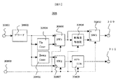
次に図6は、図3におけるデコード回路308の一構成例を示すブロック図である。図6において、309,310の各端子は図3に示したものと同じでよいため、同一の番号を付した。30801は入力端子、30802は伝送前に施されたMPEGなど圧縮操作のデコード回路、30803は入力端子、30804はアップコンバータ、30805はダウンコンバータ、30806は第一のスイッチ、30807は第二のスイッチ、30808は解像度などの制限回路、30809はAPS信号付加回路、30810は第三のスイッチである。
Next, FIG. 6 is a block diagram showing a configuration example of the
入力端子30801には、図3に記した第二のデマルチプレクス回路307の出力である、たとえば現在放送中の情報や、入出力端子306から入力される第一の記録再生装置4からの再生情報が与えられる。これは、デコード回路30802でデコードされ、送信前に施されたたとえばMPEGなどによる圧縮操作が元に戻される。このうち、少なくも映像音声などの情報は、アップコンバータ30804、ダウンコンバータ30805、第一のスイッチ30806、第二のスイッチ30807に与えられる。
At the
また図3の制御回路311からの制御信号が、入力端子30803に与えられる。さきに図4で示した制御情報からAPS105を検出した結果が、APS信号付加回路30809に与えられる。放送方式108を検出した結果が、第一のスイッチ30806、第二のスイッチ30807、第三のスイッチ30810に与えられる。さらに、解像度などの制限情報109と課金の状況から判断して決めた、解像度制限などの内容を指示する情報が、解像度などの制限回路30808に与えられる。
A control signal from the
まず、図4の放送方式108より、情報がSD情報であると判断された場合を述べる。この時、第一のスイッチ30806と第二のスイッチ30807は図6上で下側(図中bと記す)の、第三のスイッチ30810は図面上で上側(図中a)の信号を選択して、次の構成要素へ接続する。この情報は走査線数で480本ないし540本程度のインタレース信号(以下、480iないし540iと記す)である。
First, a case where the information is determined to be SD information from the
デコード回路30802の出力のうち、出力端子310から外部の第二の記録再生装置6へ送られるものは、そのまま第二のスイッチ30807を通過して、APS付加回路30809へ与えられる。図4のAPS105より、アナログ記録機器へのコピー制御情報APSを施して出力する要求を検出した場合、APS付加回路30809では、たとえば特開昭61−288582号公報に記載されるような、擬似同期信号を付加するなどして、外部の第二の記録再生回路6へ正常な情報を記録することを不可能にする。
Of the output of the
デコード回路30802の出力のうち、出力端子309から外部のディスプレイ5へ送られるものは、まずアップコンバータ30804において走査線数で1080本程度のインタレース信号(以下、1080iと記す)に変換され、見かけ上HD情報に相当する走査線数となる。その後、第一のスイッチ30806と第三のスイッチ30810を介して、出力端子309へ与えられる。
Of the output of the
次に、情報がHD情報であると判断された場合を述べる。この情報は、走査線数でたとえば1080本程度のインタレース信号(1080i)である。この時、第一のスイッチ30806と第二のスイッチ30807は図面上で上側(図中a)の、第三のスイッチ30810は図面上で下側(図中b)の信号を選択して、次の構成要素へ接続する。
Next, a case where it is determined that the information is HD information will be described. This information is, for example, about 1080 interlace signals (1080i) in terms of the number of scanning lines. At this time, the
デコード回路30802の出力のうち、出力端子310から外部の第二の記録再生装置6へ送られるものは、まずダウンコンバータ30805で走査線数を削減して、たとえば480iないし540iの信号とした後、第二のスイッチ30807を介し、さらに要求に応じてAPS付加回路30809で、擬似同期信号を付加するなどして、出力端子310へ与えられる。
Among the outputs of the
デコード回路30802の出力のうち、出力端子309から外部のディスプレイ5へ送られるものは、そのまま第一のスイッチ30806を通過して、解像度などの制限回路30808へ与えられる。図4の解像度などの制限情報109より、HD情報をたとえば装置からアナログ出力する際には、解像度などの制限をする要求を検出した場合、解像度などの制限回路30808では、水平方向をリサンプリングないしフィルタリングしてたとえば960画素程度に制限し、また垂直方向はたとえば走査線数540本程度のインタレース信号(以下540i)、あるいはプログレッシブ信号(以下540P)に変換し、制限を行うことができる。その後、第三のスイッチ30810を通過して、出力端子309へ与えられる。特にプログレッシブ信号とした場合は、インタレース信号とする場合に比べ、ユーザに不満を感じさせるような画質の低下を防ぎ、また後述するように走査線数の変換操作を簡単にすることができる。
Of the output of the
この解像度などの制限を行うか否かは、図3の制御回路311で決定され、入力端子30803から入力される制御信号に応じて制御される。出力をたとえば、(a)解像度などの制限なし、(b)540Pに制限、(c)540iに制限、の三段階で選択でき、これに応じた課金の金額が決められたとする。一般には、(a)が最も高額で続いて(b)、(c)の順となる。(c)は無料としても良い。ユーザはこのうち一つを選択しその指令は図3の入力端子316から入力され、コマンド入力回路317を介して、制御回路311へ送られる。選択された内容により、解像度などの制限回路30808は動作を決める。また、課金情報管理回路313にも選択された内容は伝えられ、モデム回路314、出力端子315より、著作権者、金融機関あるいは情報提供局などへ送られ、これに応じた金額がユーザに課金される。勿論、出力の選択は上記した三段階ではなく、たとえば(a)(b)の二段階でも良い。
Whether to limit the resolution or the like is determined by the
なお、情報がHD情報であっても解像度制限が要求されない場合、あるいは課金に応じて解像度制限をしない場合には、解像度などの制限回路30808では解像度制限をせずに入力情報をそのまま出力する。これは、第三のスイッチ30810のうち、a側の入力情報を選択することでも実現できる。
Note that even if the information is HD information, if resolution limitation is not required, or if resolution limitation is not performed according to billing, the
また、出力端子309から480i、540i、540P(あるいは720P未満)の情報が出力されて、ディスプレイ5に入力された場合、ディスプレイ5でアップコンバートして高精細情報のフォーマットに変換して表示することが多い。このアップコンバートの処理を、解像度などの制限回路30808で併せて行うこともできる。
Further, when information of 480i, 540i, 540P (or less than 720P) is output from the
なお、情報をアナログ情報に変換するDA変換回路については、ここまで触れていないが、場所は特に限定されない。ディスプレイとアナログ情報で接続するなら、第三のスイッチ3810と出力端子309との間、さらにはAPS付加回路30809と出力端子310との間などが考えられる。勿論前者の場合、出力端子309の外でディスプレイ5の前にあっても良い。ディスプレイ5とディジタル情報で接続するなら、当然ながらディスプレイ5の内部となる。この場合でも、特にディスプレイ5にアナログ出力を設ける時は、ここに解像度などの制限が必要になる場合がある。次に、HD情報かSD情報かの判断は、図4の放送方式108で判断する方法のほか、いくつか手段が考えられる。たとえば、水平同期信号の周期で判断することも可能である。解像度などの制限回路30808は、図6に示した位置のほか、図3の第一のデマルチプレクス回路305と入出力端子306との間にも置いて良い。この場合、解像度などの制限が要求された場合は、第一の記録再生装置4に記録する前にこれが施される。但しその場合には、記録情報自体も解像度制限されるため、ユーザのメリットは低下する。
A DA converter circuit that converts information into analog information has not been described so far, but the location is not particularly limited. If the display is connected with analog information, a connection between the third switch 3810 and the
図7は、図6とは異なるデコード回路308の構成例を示す。ここではアップコンバータ30804Aの位置が図6と異なり、また第一のスイッチ30806は存在しない。ここで、出力端子309へ出力される情報は次のようになる。デコード回路30802の出力が480iないし540iであるSD情報は、第三のスイッチ30810を通過した後、アップコンバータ30804Aで1080iの情報に変換されて出力端子309に与えられる。また、デコード回路30802の出力が1080iであるHD情報は、解像度などの制限回路30808で必要に応じ、540iないし540Pの情報に変換された後、やはり第三のスイッチ30810と、アップコンバータ3804Aを介し、1080iの情報に変換されて出力端子309に与えられる。この場合、もとの1080iに戻るのであるが、一度540iないし540Pとした場合は、相応の解像度制限が施されている。この場合、アップコンバータ30804Aを切離し、たとえばディスプレイ5に内蔵することも可能である。
FIG. 7 shows a configuration example of a
図6、図7において、解像度などの制限回路30808での制限を、480iないし540iなどのインタレース信号だけに変換する場合は、これとダウンコンバータ30805を共用することも可能である。
In FIGS. 6 and 7, when the limitation in the limiting
次に解像度などの制限方法を具体的に述べる。前記したとおり、水平方向の制限はリサンプリングやフィルタリングなどで可能である。ここでは残る垂直方向、すなわち走査線数の変換について模式的な図面を用いながら説明する。 Next, a method for limiting the resolution and the like will be specifically described. As described above, the restriction in the horizontal direction can be performed by resampling or filtering. Here, the remaining vertical direction, that is, the conversion of the number of scanning lines will be described with reference to schematic drawings.
まず図8、図9に示した走査線数の変換方法について述べる。図8は1080iの情報を、半分の走査線数の540iへ変換する場合、図9はこの一度540iに変換した情報を、再度1080iに戻す場合を模式的に示したものである。図中(a)は二つのフィールドのうち奇数フィールドを、(b)は偶数フィールドを示し、双方合わせて一つのフレームとなる。図中、縦方向はディスプレイの垂直方向の相対的な位置を示す。横方向の線は走査線に相当するものであり、順にAB・・、GH・・あるいはMN・・の符号を付してある。最初の1080iの情報は実線で、540iへ変換した後は点線で、再度1080iへ変換した後は二点破線で示している。 First, a method of converting the number of scanning lines shown in FIGS. 8 and 9 will be described. FIG. 8 schematically shows a case where 1080i information is converted to 540i having half the number of scanning lines, and FIG. 9 schematically shows a case where the information once converted to 540i is returned to 1080i again. In the figure, (a) shows an odd field of the two fields, and (b) shows an even field, and both are one frame. In the figure, the vertical direction indicates the relative position in the vertical direction of the display. The horizontal line corresponds to the scanning line, and the symbols AB,..., GH,. The first 1080i information is shown by a solid line, a dotted line after conversion to 540i, and a two-dot broken line after conversion to 1080i again.
図8で左側の1080iを右側の540iに変換する時、その変換前後の垂直方向の相対位置に着目すると、(a)に示した奇数フィールドでは、
M=(A+B)/2 N=(C+D)/2 ・・・式(1)
と、たとえば走査線Mを等間隔で挟む、走査線A,Bの平均値の演算をすると良い。一方、(b)に示した偶数フィールドでは、
T=H U=J ・・・式(2)
と、同じ位置にある走査線を持ってくる、すなわち一本おきに間引くと良い。
When converting 1080i on the left side to 540i on the right side in FIG. 8, paying attention to the relative position in the vertical direction before and after the conversion, in the odd field shown in (a),
M = (A + B) / 2 N = (C + D) / 2 Formula (1)
For example, the average value of the scanning lines A and B may be calculated with the scanning lines M sandwiched at equal intervals. On the other hand, in the even field shown in (b),
T = H U = J (2)
Then, it is preferable to bring scanning lines at the same position, that is, to thin out every other line.
図9で右側の540i(図8の右半分と同じ)を、左側の1080iに再変換する時、やはり前後の相対位置に着目すると、(a)に示した奇数フィールドでは、
再B=(3M+N)/4 再C=(M+3N)/4・・・式(3)
と、これらを挟む二つの走査線からの距離を考慮した、加重平均をとることになる。一方、(b)に示した偶数フィールドでは、
再H=T 再I=(T+U)/2 ・・・式(4)
と、一本おきに同じ位置にある走査線を持ってくる、また平均値演算をとるようにする。このように、特に再変換するに際して、フィールド毎に、また走査線毎に演算式を変える煩わしさは認められる。
When re-converting the right side 540i in FIG. 9 (same as the right half of FIG. 8) to the
Re B = (3M + N) / 4 Re C = (M + 3N) / 4 Equation (3)
Then, a weighted average is taken in consideration of the distance from two scanning lines sandwiching these. On the other hand, in the even field shown in (b),
Re H = T Re I = (T + U) / 2 Formula (4)
Then, every other scanning line is brought to the same position, and the average value is calculated. In this way, when reconverting in particular, the troublesomeness of changing the arithmetic expression for each field and for each scanning line is recognized.
なお、式(3),(4)に式(1),(2)を代入するとわかるように、同じ1080iの情報でもこの変換の前後で、
再B=(3A+3B+C+D)/8 再C=(A+B+3C+3D)/8
再H=H 再I=(H+J)/2 ・・・式(5)
と、同じ走査線内に、元は他の走査線にあった情報が混在し、垂直方向の解像度が失われている。この分が垂直方向の解像度の制限作用となる。また、各ライン、各フィールドでフィルタ特性が異なるので、フリッカなどの画質劣化も加わる問題はある。
As can be seen by substituting equations (1) and (2) into equations (3) and (4), the same 1080i information can be
Re B = (3A + 3B + C + D) / 8 Re C = (A + B + 3C + 3D) / 8
Re H = H Re I = (H + J) / 2 Formula (5)
In the same scanning line, information originally in the other scanning lines is mixed, and the vertical resolution is lost. This amount is a limiting effect on the resolution in the vertical direction. In addition, since the filter characteristics are different for each line and each field, there is a problem that image quality deterioration such as flicker is added.
次に図10、図11に示した走査線数の変換方法について説明する。図10は1080iの情報を、半分の走査線数の540Pへ変換する場合、図11はこの一度540Pに変換した情報を、再度1080iに戻す場合を模式的に示したものである。1080iの段階において、(a)は二つのフィールドのうち奇数フィールドを、(b)は偶数フィールドを示し、双方合わせて一つのフレームとなる。しかし540Pの段階においては、フィールドの偶奇の区別はなく、一つのフィールドが一つのフレームとなる。最初の1080iの情報は実線で、540Pへ変換した後は点線で、再度1080iへ変換した後は二点破線で示している。 Next, a method for converting the number of scanning lines shown in FIGS. 10 and 11 will be described. FIG. 10 schematically shows a case where 1080i information is converted to 540P having half the number of scanning lines, and FIG. 11 schematically shows a case where the information once converted to 540P is returned to 1080i again. At the stage of 1080i, (a) shows an odd field of the two fields, and (b) shows an even field, and both are one frame. However, at the stage of 540P, there is no distinction between even and odd fields, and one field becomes one frame. The first 1080i information is shown by a solid line, a dotted line after conversion to 540P, and a two-dot broken line after conversion to 1080i again.
図10で左側の1080iを右側の540Pに変換する時、その変換前後の垂直方向の相対位置に着目すると、たとえば変換後のMはAとBとの距離の比が1対3である。したがって、(a)に示した奇数フィールドでは、
M=(3A+B)/4 M’=(3B+C)/4 ・・・式(6)
となる。一方、(b)に示した偶数フィールドでは、
T'=(G+3H)/4 U=(H+3I)/4 ・・・式(7)
となる。
When converting the left 1080i into the right 540P in FIG. 10, focusing on the vertical relative position before and after the conversion, for example, the ratio of the distance between A and B in M after conversion is 1: 3. Therefore, in the odd field shown in (a),
M = (3A + B) / 4 M ′ = (3B + C) / 4 Formula (6)
It becomes. On the other hand, in the even field shown in (b),
T ′ = (G + 3H) / 4 U = (H + 3I) / 4 Formula (7)
It becomes.
図11で右側の540P(図10の右半分と同じ)を、左側の1080iに再変換する時、やはり前後の相対位置に着目すると、(a)に示した奇数フィールドでは、
再B=(M+3M’)/4 再C=(M’+3N)/4 ・・・式(8)
となる。一方、(b)に示した偶数フィールドでは、
再H=(3T’+U)/4 再I=(3U+U’)/4 ・・・式(9)
となる。
When re-converting the
Re B = (M + 3M ′) / 4 Re C = (M ′ + 3N) / 4 Equation (8)
It becomes. On the other hand, in the even field shown in (b),
Re-H = (3T ′ + U) / 4 Re-I = (3U + U ′) / 4 Equation (9)
It becomes.
以上から分かるように、1080iと540Pの間の変換および再変換の過程では、変換後の走査線を挟むものの3対1の加重平均をとれば良い。すなわち、前記した一度540iに変換する時のようなフィールド毎、ないし走査線毎の演算式の変更を要さず、操作の煩わしさがないという長所が認められる。 As can be seen from the above, in the process of conversion and re-conversion between 1080i and 540P, a three-to-one weighted average may be taken while sandwiching the converted scanning line. That is, there is an advantage that there is no troublesome operation because it is not necessary to change the arithmetic expression for each field or each scanning line as in the case of once converting to 540i.
なお、ここでも式(8),(9)に式(6),(7)を代入すると分かるように、
再B=(3A+10B+3C)/16 再C=(3B+10C+3D)/16
再H=(3G+10H+3I)/16 再I=(3H+10I+3J)/16
・・・以上 式(10)
と、やはり同じ走査線内に、元は他の走査線にあった情報が混在し、垂直方向の解像度が失われている。この分が解像度の制限作用となる。ただし、一旦変換する際に、プログレッシブへ変換しているため、ユーザが不満足を感じるような画質とはならないという長所がある。また、変換後の各走査線とも、元の三本の走査線の3対10対3の加重平均となり、走査線毎のフリッカが低減できるし、処理に伴うフィールド間のフリッカも生じないという特徴がある。
Note that here, as can be seen by substituting Equations (6) and (7) into Equations (8) and (9),
Re B = (3A + 10B + 3C) / 16 Re C = (3B + 10C + 3D) / 16
Re H = (3G + 10H + 3I) / 16 Re I = (3H + 10I + 3J) / 16
... or more Formula (10)
In the same scanning line, the information originally in the other scanning lines is mixed, and the vertical resolution is lost. This is the resolution limiting action. However, there is an advantage that the image quality does not make the user feel unsatisfied because the conversion is made progressively when converting once. Each of the converted scanning lines is a weighted average of 3 to 10 to 3 of the original three scanning lines, and flicker for each scanning line can be reduced, and flicker between fields due to processing does not occur. There is.
なお、ここまでの説明で、情報を装置から出力する際の解像度などの制限は、アナログ出力に対して行う場合を主に述べてきたが、ディジタル出力に対しても、本発明は同様に適用できることは、言うまでもない。 In the above description, the limitation on resolution and the like when outputting information from the apparatus has been mainly described for analog output. However, the present invention is similarly applied to digital output. Needless to say, what you can do.
また、受信装置3の出力信号としては解像度などの制限をした、540iの信号として出力する場合には図8に示す変換、即ち、式(1)、(2)を、540Pの信号として出力する場合には図10に示す変換、即ち、式(6)、(7)を、図6、7に示す解像度などの制限回路30808に適用すれば良い。
In addition, when the output signal of the receiving
また、受信装置3の出力信号としては、解像度などの制限を行った後に高精細の信号フォーマットで出力する場合は、図8、9に示す変換、即ち、式(5)、または図10、11に示す変換、即ち、式(10)を解像度などの制限回路30808に適用すれば良い。式(5)、(10)に示す処理を用いれば、二回の変換処理を一度に行え、信号処理を効率良く行うことができる。また、図6、7に示す実施例では回路ブロック構成を示したが、マイクロプロセッサを用いた演算信号処理で実現しても良い。
When the output signal of the receiving
さらにはまた、図8、9、10、11に示す実施例では、2ラインの情報を用いて演算を行う場合に付いて示したが、例えば4ラインの情報を用いて演算を行えば垂直の解像度の低下を少なくできる。本発明は、式(1)から(10)に示すフィルタ係数に限定するものではなく、さらに高次のフィルタを用いれば、垂直解像度の低下をより少なくすることができる。 Furthermore, in the embodiments shown in FIGS. 8, 9, 10, and 11, the case where the calculation is performed using the information of two lines is shown. However, if the calculation is performed using the information of four lines, for example, the calculation is performed vertically. Decrease in resolution can be reduced. The present invention is not limited to the filter coefficients shown in the equations (1) to (10), and if a higher-order filter is used, the vertical resolution can be further reduced.
図1の受信装置3とディスプレイ5との間が、アナログ信号で接続される場合は本発明が特に有効である。ディジタル信号で接続される場合、受信装置3とディスプレイ5が同じ筐体内にある場合などは、必ずしも本発明による解像度制限の必要はないが、この場合でもアナログ信号を外部へ出力する時は、これに本発明を適用することが有効であり、その範疇にある。
The present invention is particularly effective when the receiving
図12は、本発明による受信装置(入出力装置)3の構成の別な例を示す。さきの図3の実施例で示したものは、たとえば一般家庭で用いるに適したものであり、ユーザが課金されても、その場では現金を必要としないよう構成されている。図12はこれに対し、たとえば宿泊所の居室に置かれる場合に適したものである。ここでは、入金検出回路319が追加されている。宿泊所などでは、館内放送でパッケージソフトの放映などを行っており、有料で供給されるものもある。このような場合、金額に応じた解像度の制限を施して提供する場合に有効である。入力端子318からは現金が投入され、入金検出回路319で検出された金額情報(無料を含んでも良い)が制御回路311へ伝えられ、デコード回路308でこの金額に見合った解像度の制限などが施される。これは、宿泊所のオーナなどが現金を回収するに適したものであるが、前記したような放送など、外部の機関が回収するものに備え、課金情報管理回路313とモデム回路314などは、図3と同様に備えていても良い。
FIG. 12 shows another example of the configuration of the receiving device (input / output device) 3 according to the present invention. The embodiment shown in the embodiment of FIG. 3 is suitable for use in a general household, for example, and is configured so that cash is not required on the spot even if the user is charged. On the other hand, FIG. 12 is suitable, for example, when it is placed in a room in an accommodation. Here, a deposit detection circuit 319 is added. In accommodations, etc., package software is broadcasted in the hall, and some are supplied for a fee. In such a case, it is effective when providing a resolution limited according to the amount of money. Cash is input from the input terminal 318, and the amount information (including free of charge) detected by the receipt detection circuit 319 is transmitted to the
このパッケージソフトは、一般にはディスク、テープなどの記録媒体に、予め映像音声などの情報データを記録した形で上記したオーナや一般消費者へ提供される。この映像音声などの情報データとともに、図4で示した制御情報信号を記録しておけば良い。特に放送方式108、解像度などの制限情報109を記録しておけば、前記した実施例と同様の再生時の課金と、これに見合った解像度制限を施すことができる。放送方式108に関しては、パッケージソフトの場合は放送の場合と異なるが、用いたテレビジョン方式が同類の放送方式を記すと良い。
This package software is generally provided to the above-mentioned owners and general consumers in a form in which information data such as video and audio is recorded in advance on a recording medium such as a disk or tape. The control information signal shown in FIG. 4 may be recorded together with the information data such as video and audio. In particular, if restriction information 109 such as the
解像度などの制限動作とこれに対する課金条件が、全ての情報に対して一律に決まっていない場合は、各情報毎に課金条件を付すようにすると良い。たとえば、複数種類の課金条件を準備して各々にコード番号を付し、これを図4の情報制御信号に加える。図3の受信装置3でこれを検出して、制御回路311から課金情報管理回路313へ知らせるようにすれば、情報毎に異なる課金を施すことができる。
If the limiting operation such as resolution and the charging conditions for this are not uniformly determined for all information, it is preferable to add a charging condition for each piece of information. For example, a plurality of types of charging conditions are prepared, each is assigned a code number, and this is added to the information control signal of FIG. If this is detected by the receiving
1・・・・・・情報提供局(送信装置)
16・・・・・管理情報付与回路
108・・・・放送方式
109・・・・解像度などの制限情報
2・・・・・・中継局
3・・・・・・受信装置(入出力装置)
306・・・・入出力端子
308・・・・デコード回路
30801・・入力端子
30802・・デコード回路
30803・・入力端子
30804・・アップコンバータ
30805・・ダウンコンバータ
30806・・第一のスイッチ
30807・・第二のスイッチ
30808・・解像度等制限回路
30809・・APS信号付加回路
30810・・第三のスイッチ
309・・・・出力端子
310・・・・出力端子
311・・・・制御回路
312・・・・情報管理回路
313・・・・課金情報管理回路
314・・・・モデム(MODEM)回路
315・・・・出力端子
316・・・・入力端子
317・・・・コマンド入力回路
318・・・・入力端子
319・・・・入金検出回路
4・・・・・・第一の記録再生装置
5・・・・・・ディスプレイ
6・・・・・・第二の記録再生装置
1. Information provider (transmitter)
16... Management
Input /
Claims (3)
前記映像情報とコピー制御情報とを受信する受信手段と、
前記受信手段で受信した前記映像情報を外部装置へ出力する出力手段と、
前記映像情報が有料の映像情報であるときに契約情報を管理する情報管理手段と、
前記受信手段、前記出力手段および前記情報管理手段を制御する制御手段とを備え、
前記出力手段は、受信した前記映像情報をディジタル信号として出力する第1の出力と、受信した前記映像情報をアナログ信号として出力する第2の出力とを有し、
前記制御手段は、前記受信手段において受信する前記映像情報が有料の映像情報であるときに、受信契約がされているかどうかを判断し、前記受信契約がされている場合に前記映像情報を受信して出力するように制御し、
前記出力手段からの出力状態は、
前記コピー制御情報がコピー可である前記映像情報を前記第1の出力よりディジタル信号として出力する場合に、前記映像情報を暗号化しないで、かつ、前記映像情報の解像度の制限を行わないで出力可能な第1の状態と、
前記コピー制御情報がコピー可である前記映像情報を前記第2の出力よりアナログ信号として出力する場合に、前記映像情報の解像度の制限を行わないで出力可能な第2の状態と、
前記コピー制御情報がコピーの制限を示している前記映像情報を前記第2の出力よりアナログ信号として出力する場合に、前記映像情報の解像度を制限して出力する第3の状態と、
前記映像情報を前記第1の出力よりディジタル信号として暗号化して出力する場合に、前記映像情報の解像度の制限を行わないで出力可能な第4の状態と、
を有することを特徴とする映像情報受信装置。 In a video information receiving device that receives video information transmitted via broadcast or communication means and outputs it to an external device,
Receiving means for receiving the video information and copy control information;
Output means for outputting the video information received by the receiving means to an external device;
Information management means for managing contract information when the video information is paid video information;
Control means for controlling the receiving means, the output means and the information management means,
The output means has a first output for outputting the received video information as a digital signal, and a second output for outputting the received video information as an analog signal,
The control means determines whether a receiving contract is made when the video information received by the receiving means is paid video information, and receives the video information when the receiving contract is made. Control to output
The output state from the output means is:
When the video information for which the copy control information can be copied is output as a digital signal from the first output , the video information is not encrypted and output without limiting the resolution of the video information. A possible first state;
A second state that can be output without limiting the resolution of the video information when the video information that the copy control information is copyable is output as an analog signal from the second output ;
A third state in which the resolution of the video information is limited and output when the video information whose copy control information indicates copy restriction is output as an analog signal from the second output ;
A fourth state in which the video information is output as a digital signal encrypted from the first output and can be output without limiting the resolution of the video information;
A video information receiving apparatus comprising:
前記映像情報が有料の映像情報であるときに、
受信契約がされているかどうかを判断するステップと、
受信契約がされている場合に、前記映像情報を受信してディジタル信号として第1の出力から出力する、または、アナログ信号として第2の出力から出力するステップとを備え、
前記映像情報を受信して出力するステップにおける出力状態は、
前記コピー制御情報がコピー可である前記映像情報を前記第1の出力よりディジタル信号として出力する場合に、前記映像情報を暗号化しないで、かつ、前記映像情報の解像度の制限を行わないで出力可能な第1の状態と、
前記コピー制御情報がコピー可である前記映像情報を前記第2の出力よりアナログ信号として出力する場合に、前記映像情報の解像度の制限を行わないで出力可能な第2の状態と、
前記コピー制御情報がコピーの制限を示している前記映像情報を前記第2の出力よりアナログ信号として出力する場合に、前記映像情報の解像度を制限して出力する第3の状態と、
前記映像情報を前記第1の出力よりディジタル信号として暗号化して出力する場合に、前記映像情報の解像度の制限を行わないで出力可能な第4の状態と、
を有することを特徴とする映像情報受信方法。 In a video information receiving method for receiving and outputting video information transmitted together with copy control information via broadcast or communication means at a receiving device,
When the video information is paid video information,
Determining whether a subscription has been made,
Receiving a video signal and outputting the digital information from the first output as a digital signal, or outputting from the second output as an analog signal when a reception contract is made,
The output state in the step of receiving and outputting the video information is:
When the video information for which the copy control information can be copied is output as a digital signal from the first output , the video information is not encrypted and output without limiting the resolution of the video information. A possible first state;
A second state that can be output without limiting the resolution of the video information when the video information that the copy control information is copyable is output as an analog signal from the second output ;
A third state in which the resolution of the video information is limited and output when the video information whose copy control information indicates copy restriction is output as an analog signal from the second output ;
A fourth state in which the video information is output as a digital signal encrypted from the first output and can be output without limiting the resolution of the video information;
A video information receiving method comprising:
前記映像情報が有料の映像情報であるときに、
前記送信装置において、前記映像情報を前記映像情報が有料の映像情報であることを示す情報とコピー制御情報とともに送信するステップと、
前記受信装置において、送信された前記映像情報を受信する際に、受信契約がされているかどうかを判断し、前記受信契約がされている場合には、送信された前記映像情報を受信してディジタル信号として第1の出力から、または、アナログ信号として第2の出力から出力するステップとを備え、
前記映像情報を受信して出力するステップにおける出力状態は、
前記コピー制御情報がコピー可である前記映像情報を前記第1の出力よりディジタル信号として出力する場合に、前記映像情報を暗号化しないで、かつ、前記映像情報の解像度の制限を行わないで出力可能な第1の状態と、
前記コピー制御情報がコピー可である前記映像情報を前記第2の出力よりアナログ信号として出力する場合に、前記映像情報の解像度の制限を行わないで出力可能な第2の状態と、
前記コピー制御情報がコピーの制限を示している前記映像情報を前記第2の出力よりアナログ信号として出力する場合に、前記映像情報の解像度を制限して出力する第3の状態と、
前記映像情報を前記第1の出力よりディジタル信号として暗号化して出力する場合に、前記映像情報の解像度の制限を行わないで出力可能な第4の状態と、
を有することを特徴とする映像情報送受信方法。 In a video information transmission / reception method for transmitting video information from a transmission device via broadcast or communication means, and receiving at a reception device,
When the video information is paid video information,
In the transmission device, the steps of both transmitting information and the copy control information indicating that the image information the image information is the image information of the toll,
In the receiving device, when receiving the transmitted video information, it is determined whether or not a reception contract is made. If the reception contract is made, the received video information is received and digitally received. Outputting from the first output as a signal or from the second output as an analog signal,
The output state in the step of receiving and outputting the video information is:
When the video information for which the copy control information can be copied is output as a digital signal from the first output , the video information is not encrypted and output without limiting the resolution of the video information. A possible first state;
A second state that can be output without limiting the resolution of the video information when the video information that the copy control information is copyable is output as an analog signal from the second output ;
A third state in which the resolution of the video information is limited and output when the video information whose copy control information indicates copy restriction is output as an analog signal from the second output ;
A fourth state in which the video information is output as a digital signal encrypted from the first output and can be output without limiting the resolution of the video information;
A video information transmission / reception method comprising:
Priority Applications (1)
| Application Number | Priority Date | Filing Date | Title |
|---|---|---|---|
| JP2009102556A JP4654302B2 (en) | 2009-04-21 | 2009-04-21 | Video information receiving apparatus, video information receiving method, and video information transmitting / receiving method |
Applications Claiming Priority (1)
| Application Number | Priority Date | Filing Date | Title |
|---|---|---|---|
| JP2009102556A JP4654302B2 (en) | 2009-04-21 | 2009-04-21 | Video information receiving apparatus, video information receiving method, and video information transmitting / receiving method |
Related Parent Applications (1)
| Application Number | Title | Priority Date | Filing Date |
|---|---|---|---|
| JP2001053460A Division JP4474062B2 (en) | 2001-02-28 | 2001-02-28 | Video information receiving apparatus, video information receiving method, and video information transmitting / receiving method |
Related Child Applications (1)
| Application Number | Title | Priority Date | Filing Date |
|---|---|---|---|
| JP2010142178A Division JP4734464B2 (en) | 2010-06-23 | 2010-06-23 | Video information receiving apparatus, video information receiving method, and video information transmitting / receiving method |
Publications (3)
| Publication Number | Publication Date |
|---|---|
| JP2009171605A JP2009171605A (en) | 2009-07-30 |
| JP2009171605A5 JP2009171605A5 (en) | 2010-09-02 |
| JP4654302B2 true JP4654302B2 (en) | 2011-03-16 |
Family
ID=40972186
Family Applications (1)
| Application Number | Title | Priority Date | Filing Date |
|---|---|---|---|
| JP2009102556A Expired - Lifetime JP4654302B2 (en) | 2009-04-21 | 2009-04-21 | Video information receiving apparatus, video information receiving method, and video information transmitting / receiving method |
Country Status (1)
| Country | Link |
|---|---|
| JP (1) | JP4654302B2 (en) |
Citations (6)
| Publication number | Priority date | Publication date | Assignee | Title |
|---|---|---|---|---|
| JPH0715715A (en) * | 1993-06-15 | 1995-01-17 | Nec Corp | Image ciphering transmission system |
| JPH07115638A (en) * | 1993-10-18 | 1995-05-02 | Canon Inc | Video transmitter |
| JPH088852A (en) * | 1994-06-23 | 1996-01-12 | Toshiba Corp | Information distribution device and information distribution method |
| JPH11164281A (en) * | 1997-11-28 | 1999-06-18 | Toshiba Corp | Digital broadcast receiver |
| JP2000004422A (en) * | 1998-06-15 | 2000-01-07 | Matsushita Electric Ind Co Ltd | Digital signal recording and reproducing device and system for charging at time of reproduction using the same device |
| JP2000113050A (en) * | 1998-10-01 | 2000-04-21 | Hitachi Ltd | Electronic book system |
-
2009
- 2009-04-21 JP JP2009102556A patent/JP4654302B2/en not_active Expired - Lifetime
Patent Citations (6)
| Publication number | Priority date | Publication date | Assignee | Title |
|---|---|---|---|---|
| JPH0715715A (en) * | 1993-06-15 | 1995-01-17 | Nec Corp | Image ciphering transmission system |
| JPH07115638A (en) * | 1993-10-18 | 1995-05-02 | Canon Inc | Video transmitter |
| JPH088852A (en) * | 1994-06-23 | 1996-01-12 | Toshiba Corp | Information distribution device and information distribution method |
| JPH11164281A (en) * | 1997-11-28 | 1999-06-18 | Toshiba Corp | Digital broadcast receiver |
| JP2000004422A (en) * | 1998-06-15 | 2000-01-07 | Matsushita Electric Ind Co Ltd | Digital signal recording and reproducing device and system for charging at time of reproduction using the same device |
| JP2000113050A (en) * | 1998-10-01 | 2000-04-21 | Hitachi Ltd | Electronic book system |
Also Published As
| Publication number | Publication date |
|---|---|
| JP2009171605A (en) | 2009-07-30 |
Similar Documents
| Publication | Publication Date | Title |
|---|---|---|
| JP4474062B2 (en) | Video information receiving apparatus, video information receiving method, and video information transmitting / receiving method | |
| EP1534020A2 (en) | Method/apparatus for receiving and/or reproducing digital signal | |
| JP2012070416A (en) | Receiver and recording method | |
| US7538819B2 (en) | Adaptive video image information processing system | |
| JPH08297919A (en) | Method and device for receiving digital signal | |
| JP4654302B2 (en) | Video information receiving apparatus, video information receiving method, and video information transmitting / receiving method | |
| JP4734482B2 (en) | Video information receiving apparatus, video information receiving method, and video information transmitting / receiving method | |
| JP4734464B2 (en) | Video information receiving apparatus, video information receiving method, and video information transmitting / receiving method | |
| JP4940223B2 (en) | Video information transmitting apparatus, video information transmitting method, and video information transmitting / receiving method | |
| JP4945538B2 (en) | Video information transmitting apparatus, video information transmitting method, and video information transmitting / receiving method | |
| JP4225365B2 (en) | Video information transmitting apparatus and video information transmitting method | |
| JP2011130473A (en) | Video information input/output device, and video information recording medium | |
| JP2008022579A (en) | Video information output device and video information output method | |
| JP2009089423A (en) | Video receiving apparatus and information receiving method | |
| JP4876189B2 (en) | Digital information receiving apparatus and digital information recording / reproducing method | |
| JP2003006977A (en) | Digital information reproducing device | |
| JP2002218412A (en) | Device and method for inputting-outputting video information and transmitter | |
| JP2008022578A (en) | Video information receiver and video information receiving method | |
| JP2009089424A (en) | Video information output apparatus, video information output method, video information transmission apparatus, video information transmission method, video information reception apparatus and video information reproduction apparatus | |
| JP2003110980A (en) | Receiver and charging system | |
| JP3111822B2 (en) | Information recording device and information recording / reproducing device | |
| JP3478121B2 (en) | Signal processing device, recording / reproducing device, and billing method | |
| KR100862598B1 (en) | An adaptive video image information processing system | |
| JP2003009078A (en) | Method and device for receiving digital signal | |
| JP2002215831A (en) | Electronic cinema system and ticket issuing device |
Legal Events
| Date | Code | Title | Description |
|---|---|---|---|
| A521 | Request for written amendment filed |
Free format text: JAPANESE INTERMEDIATE CODE: A523 Effective date: 20090421 |
|
| A621 | Written request for application examination |
Free format text: JAPANESE INTERMEDIATE CODE: A621 Effective date: 20090421 |
|
| A711 | Notification of change in applicant |
Free format text: JAPANESE INTERMEDIATE CODE: A712 Effective date: 20090903 |
|
| A521 | Request for written amendment filed |
Free format text: JAPANESE INTERMEDIATE CODE: A523 Effective date: 20100623 |
|
| A871 | Explanation of circumstances concerning accelerated examination |
Free format text: JAPANESE INTERMEDIATE CODE: A871 Effective date: 20100623 |
|
| A521 | Request for written amendment filed |
Free format text: JAPANESE INTERMEDIATE CODE: A523 Effective date: 20100623 |
|
| A975 | Report on accelerated examination |
Free format text: JAPANESE INTERMEDIATE CODE: A971005 Effective date: 20100708 |
|
| A131 | Notification of reasons for refusal |
Free format text: JAPANESE INTERMEDIATE CODE: A131 Effective date: 20100727 |
|
| A521 | Request for written amendment filed |
Free format text: JAPANESE INTERMEDIATE CODE: A523 Effective date: 20100917 |
|
| TRDD | Decision of grant or rejection written | ||
| A01 | Written decision to grant a patent or to grant a registration (utility model) |
Free format text: JAPANESE INTERMEDIATE CODE: A01 Effective date: 20101214 |
|
| A01 | Written decision to grant a patent or to grant a registration (utility model) |
Free format text: JAPANESE INTERMEDIATE CODE: A01 |
|
| A61 | First payment of annual fees (during grant procedure) |
Free format text: JAPANESE INTERMEDIATE CODE: A61 Effective date: 20101220 |
|
| R150 | Certificate of patent or registration of utility model |
Ref document number: 4654302 Country of ref document: JP Free format text: JAPANESE INTERMEDIATE CODE: R150 Free format text: JAPANESE INTERMEDIATE CODE: R150 |
|
| FPAY | Renewal fee payment (event date is renewal date of database) |
Free format text: PAYMENT UNTIL: 20131224 Year of fee payment: 3 |
|
| S111 | Request for change of ownership or part of ownership |
Free format text: JAPANESE INTERMEDIATE CODE: R313111 |
|
| R350 | Written notification of registration of transfer |
Free format text: JAPANESE INTERMEDIATE CODE: R350 |
|
| R250 | Receipt of annual fees |
Free format text: JAPANESE INTERMEDIATE CODE: R250 |
|
| R250 | Receipt of annual fees |
Free format text: JAPANESE INTERMEDIATE CODE: R250 |
|
| R250 | Receipt of annual fees |
Free format text: JAPANESE INTERMEDIATE CODE: R250 |
|
| EXPY | Cancellation because of completion of term |